US7411895B2 - Controlled superposition coding in multi-user communication systems - Google Patents
Controlled superposition coding in multi-user communication systemsDownload PDFInfo
- Publication number
- US7411895B2 US7411895B2US10/782,186US78218604AUS7411895B2US 7411895 B2US7411895 B2US 7411895B2US 78218604 AUS78218604 AUS 78218604AUS 7411895 B2US7411895 B2US 7411895B2
- Authority
- US
- United States
- Prior art keywords
- channel
- base station
- wireless terminal
- signal
- communications
- Prior art date
- Legal status (The legal status is an assumption and is not a legal conclusion. Google has not performed a legal analysis and makes no representation as to the accuracy of the status listed.)
- Expired - Lifetime, expires
Links
Images


Classifications
- H—ELECTRICITY
- H04—ELECTRIC COMMUNICATION TECHNIQUE
- H04L—TRANSMISSION OF DIGITAL INFORMATION, e.g. TELEGRAPHIC COMMUNICATION
- H04L5/00—Arrangements affording multiple use of the transmission path
- H04L5/0001—Arrangements for dividing the transmission path
- H04L5/0014—Three-dimensional division
- H—ELECTRICITY
- H04—ELECTRIC COMMUNICATION TECHNIQUE
- H04W—WIRELESS COMMUNICATION NETWORKS
- H04W52/00—Power management, e.g. Transmission Power Control [TPC] or power classes
- H04W52/04—Transmission power control [TPC]
- H04W52/18—TPC being performed according to specific parameters
- H04W52/28—TPC being performed according to specific parameters using user profile, e.g. mobile speed, priority or network state, e.g. standby, idle or non-transmission
- H04W52/283—Power depending on the position of the mobile
- H—ELECTRICITY
- H04—ELECTRIC COMMUNICATION TECHNIQUE
- H04L—TRANSMISSION OF DIGITAL INFORMATION, e.g. TELEGRAPHIC COMMUNICATION
- H04L1/00—Arrangements for detecting or preventing errors in the information received
- H04L1/12—Arrangements for detecting or preventing errors in the information received by using return channel
- H04L1/16—Arrangements for detecting or preventing errors in the information received by using return channel in which the return channel carries supervisory signals, e.g. repetition request signals
- H04L1/1607—Details of the supervisory signal
- H—ELECTRICITY
- H04—ELECTRIC COMMUNICATION TECHNIQUE
- H04L—TRANSMISSION OF DIGITAL INFORMATION, e.g. TELEGRAPHIC COMMUNICATION
- H04L27/00—Modulated-carrier systems
- H04L27/26—Systems using multi-frequency codes
- H04L27/2601—Multicarrier modulation systems
- H04L27/2602—Signal structure
- H04L27/2604—Multiresolution systems
- H—ELECTRICITY
- H04—ELECTRIC COMMUNICATION TECHNIQUE
- H04L—TRANSMISSION OF DIGITAL INFORMATION, e.g. TELEGRAPHIC COMMUNICATION
- H04L27/00—Modulated-carrier systems
- H04L27/32—Carrier systems characterised by combinations of two or more of the types covered by groups H04L27/02, H04L27/10, H04L27/18 or H04L27/26
- H04L27/34—Amplitude- and phase-modulated carrier systems, e.g. quadrature-amplitude modulated carrier systems
- H04L27/3488—Multiresolution systems
- H—ELECTRICITY
- H04—ELECTRIC COMMUNICATION TECHNIQUE
- H04L—TRANSMISSION OF DIGITAL INFORMATION, e.g. TELEGRAPHIC COMMUNICATION
- H04L5/00—Arrangements affording multiple use of the transmission path
- H04L5/0001—Arrangements for dividing the transmission path
- H04L5/0003—Two-dimensional division
- H04L5/0005—Time-frequency
- H—ELECTRICITY
- H04—ELECTRIC COMMUNICATION TECHNIQUE
- H04L—TRANSMISSION OF DIGITAL INFORMATION, e.g. TELEGRAPHIC COMMUNICATION
- H04L5/00—Arrangements affording multiple use of the transmission path
- H04L5/0001—Arrangements for dividing the transmission path
- H04L5/0014—Three-dimensional division
- H04L5/0016—Time-frequency-code
- H—ELECTRICITY
- H04—ELECTRIC COMMUNICATION TECHNIQUE
- H04L—TRANSMISSION OF DIGITAL INFORMATION, e.g. TELEGRAPHIC COMMUNICATION
- H04L5/00—Arrangements affording multiple use of the transmission path
- H04L5/02—Channels characterised by the type of signal
- H04L5/04—Channels characterised by the type of signal the signals being represented by different amplitudes or polarities, e.g. quadriplex
- H—ELECTRICITY
- H04—ELECTRIC COMMUNICATION TECHNIQUE
- H04W—WIRELESS COMMUNICATION NETWORKS
- H04W52/00—Power management, e.g. Transmission Power Control [TPC] or power classes
- H04W52/04—Transmission power control [TPC]
- H—ELECTRICITY
- H04—ELECTRIC COMMUNICATION TECHNIQUE
- H04L—TRANSMISSION OF DIGITAL INFORMATION, e.g. TELEGRAPHIC COMMUNICATION
- H04L1/00—Arrangements for detecting or preventing errors in the information received
- H04L1/12—Arrangements for detecting or preventing errors in the information received by using return channel
- H04L1/16—Arrangements for detecting or preventing errors in the information received by using return channel in which the return channel carries supervisory signals, e.g. repetition request signals
- H04L1/18—Automatic repetition systems, e.g. Van Duuren systems
- H04L1/1829—Arrangements specially adapted for the receiver end
- H04L1/1861—Physical mapping arrangements
- H—ELECTRICITY
- H04—ELECTRIC COMMUNICATION TECHNIQUE
- H04W—WIRELESS COMMUNICATION NETWORKS
- H04W52/00—Power management, e.g. Transmission Power Control [TPC] or power classes
- H04W52/04—Transmission power control [TPC]
- H04W52/18—TPC being performed according to specific parameters
- H04W52/24—TPC being performed according to specific parameters using SIR [Signal to Interference Ratio] or other wireless path parameters
Definitions
- the present inventionis directed to improved methods of coding and transmitting in a wireless communications system, and more specifically to improved methods using controlled superposition coding suitable for use in, e.g., a multi-user communications system.
- Multi-user communication systemsinvolve several transmitters and receivers communicating with each other and may use one or more communications methods.
- multi-user communication methodsmay be categorized into one of two scenarios:
- the broadcast communications methodis commonly known in the communications and information theory literature as the ‘broadcast channel’.
- the ‘broadcast channel’refers to each of the physical communication channels between the transmitter and the multiple receivers as well as the communication resources used by the transmitter to communicate.
- the multiple-access communications methodis widely known as the ‘multiple-access channel’.
- the ‘multiple-access channel’refers to the physical communication channels between the multiple transmitters and the common receiver, along with the communication resources used by the transmitters.
- the broadcast communications methodis frequently used to implement the downlink communication channel in a typical cellular wireless system while the uplink channel in such a system is commonly implemented using the multiple-access communications method.
- the transmission resource in a multi-user communication systemcan generally be represented in time, frequency or code space.
- Information theorysuggests that the capacity of the system can be increased over other communication techniques in both the broadcast scenario and the multiple-access scenario.
- the capacity of the systemcan be increased over other communication techniques.
- the technique used to transmit simultaneously to multiple users over the same transmission resourceis also known as ‘superposition coding’.
- FIG. 1is a graph 100 plotting the achievable rates in a broadcast channel for a first and second user for three different transmission strategies.
- Vertical axis 102represents the rate for the stronger receiver, while horizontal axis 104 represents the rate for the weaker receiver.
- Line 106shows achievable rates for a time division multiplexing (TDM) strategy.
- Line 108shows achievable rates for a frequency division multiplexing (FDM) strategy.
- Line 110shows maximum capacity achievable rates.
- the transmitterallocates a certain fraction of the bandwidth, ⁇ , and a fraction of the available power, ⁇ , to the first user.
- the second usergets the remaining fractions of bandwidth and power. Having allocated these fractions, the transmitter communicates with the two receivers simultaneously.
- the rate regioncan be characterized by the following equations.
- R 1W ⁇ ⁇ log ⁇ ( 1 + ⁇ ⁇ ⁇ P N 1 )
- R 2W ⁇ ⁇ log ⁇ ( 1 + ( 1 - ⁇ ) ⁇ P ⁇ ⁇ ⁇ P + N 2 )
- dash/dot curve line 110corresponding to ‘CAPACITY’ as shown in FIG. 1 .
- FIG. 2is a graph 200 illustrating a high power QPSK signal and a low power QPSK signal superposed on the high power QPSK signal.
- Vertical axis 202represents Q-component signal strength while horizontal axis 204 represents P-component signal strength.
- the example of FIG. 2assumes QPSK modulation, the choice of modulation sets is not restrictive, and, in general, other modulation sets may be alternatively used.
- the example FIG. 2is sketched out for an exemplary case of two users, while the concept may be generalized and applied in a straightforward manner to multiple users. Assume that the transmitter has a total transmit power budget P.
- the first receiverreferred to as ‘weaker receiver’
- the second receiverreferred to as ‘stronger receiver’
- Four circles 206filled in with a pattern, represent the QPSK constellation points to be transmitted at high power (better protected), (1 ⁇ )P, to the weaker receiver.
- additional informationis conveyed to the stronger receiver at low power (less protected), ⁇ P, also using a QPSK constellation.
- arrow 208 of magnitude ⁇ ((1 ⁇ )P)provides an indication of the high transmission power
- arrow 210 ⁇ ( ⁇ P)provides an indication of the low transmission power.
- the actually transmitted symbolswhich combine both the high power and low power signals, are represented as blank circles 212 in the figure.
- a key concept that this illustration conveysis that the transmitter communicates to both users simultaneously using the same transmission resource.
- the receiver strategyis straightforward.
- the weaker receiversees the high power QPSK constellation with a low-power signal superposed on it.
- the SNR experienced by the weaker receivermay be insufficient to resolve the low-power signal, so the low power signal appears as noise and slightly degrades the SNR when the weaker receiver decodes the high power signal.
- the SNR experienced by the stronger receiveris sufficient to resolve both the high power and low power QPSK constellation points.
- the stronger receiver's strategyis to decode the high-power points (which are intended for the weaker receiver) first, remove their contribution from the composite signal, and then decode the low-power signal.
- New implementations using superposition coding methodsmay need methods to convey information between transmitters(s) and receiver(s) concerning the superposition coding, e.g., such as the temporary weaker/stronger assignment information.
- Methods of communicating such informationthat minimize overhead, where possible, and/or combine or link temporary assignment designations between multiple communication channel segments, e.g., an assignment channel segment and a traffic channel segment, would be advantageous.
- the present inventionis directed to new and novel methods of using superposition coding in a communications systems, e.g., a multi-user communications system.
- Superposition codingoccurs in a downlink and/or an uplink.
- Superposition coding in accordance with the inventionoccurs in the case of the downlink by transmissions to different wireless terminals from a base station using the same communications resource, e.g., simultaneously with the same frequencies.
- Superposition coding in accordance with the inventionoccurs in the case of the uplink by transmissions from different wireless terminals to a base station using the same communications resource.
- the signalscombine in the communications channel resulting in one transmission being superimposed on the other transmission.
- the devicee.g., base station
- receiving the superimposed signalsuses superposition decoding techniques to recover both signals.
- assignments of channel segments to multiple wireless terminalsis controlled by the base station.
- the transmission power levelsare controlled by the base station so that the received power levels are very different to facilitate superposition decoding.
- the transmission power levelsare controlled by the wireless terminals sharing the same uplink communications resource, e.g., time slot and frequency, to make sure that the received signals from the different devices at the base station will have different received power levels facilitating superposition decoding.
- the base stationmaintains information regarding the quality of the communications channels between individual wireless terminals and the base station.
- a communications channel segmentis assigned to two or more wireless terminals having at least a minimum difference, e.g., a 3, 5 or 10 dB difference, in the quality of their communications channels from the base station in the downlink case or communications channels to the base station in the uplink case.
- Channel assignmentsare transmitted to wireless terminals which are to share a traffic channel segment. The assignment conveys which wireless terminals are to simultaneously use a communications channel segment and, in addition, which of the assigned devices is to transmit (in the uplink case) or receive (in the downlink case) the strong or weak signal. Assignment messages may be transmitted as superimposed signals.
- this documentassumes that two signals are superimposed to form a superposition coding signal. However, more than two signals can be superimposed. The invention is applicable to the cases where more than two signals are superimposed to form a superposition coding signal.
- the two signals of a superposition coding signalare respectively called the strong signal and the weak signal, where the strong signal is the one with high received power and the weak signal is the one with low received power.
- the strong signalis the one with high received power
- the weak signalis the one with low received power.
- the weaker useris the one with worse channel condition.
- a given wireless terminalmay be the strong user when it shares the resource with another wireless terminal, and be the weaker user when it shares the resource with a third wireless terminal.
- the stronger userwill be assigned to operate transmitting the signal which will be received by the base station as the strong signal and the weaker user will normally be assigned to operate transmitting the signal which will be received by the base station as the weak signal. This avoids generating excessive interference to other base stations or requiring excessive peak transmission power from the wireless terminal.
- the stronger useris also called stronger transmitter and the weaker user is also called weaker transmitter.
- the stronger userwill be assigned to operate receiving the weak signal and the weaker user will normally be assigned to operate receiving the strong signal. This helps to improve the link reliability of the weaker user while not wasting power to the stronger user.
- the stronger useris also called stronger receiver and the weaker user is also called weaker receiver.
- Channel assignments transmitted to wireless terminals which are to share a traffic channel segmentmay also be made using superposition coding.
- channel assignmentsare generally made by the base station and transmitted in the downlink.
- the assignment sent to the stronger useris transmitted with the weak signal and the assignment sent to the weaker user is transmitted with the strong signal.
- the wireless terminalknows that it is considered by the base station as the weaker user, i.e., the weaker transmitter in the case where the wireless terminal is assigned an uplink traffic channel or the weaker receiver in the case where the wireless terminal is assigned a downlink traffic channel.
- the wireless terminalknows that it is considered by the base station as the stronger user, i.e., the stronger transmitter where the wireless terminal is assigned an uplink traffic channel or the stronger receiver where the wireless terminal is assigned a downlink traffic channel.
- superposition codingcan be used in an opportunistic manner. That is, superposition coding may be used when wireless terminals with sufficiently different channel conditions are available to be paired to share a communications channel segment. In cases where a sufficient difference in received power levels may not be achieved, e.g., due to an insufficient different in channel conditions between devices or insufficient transmission power capabilities, wireless terminals are not scheduled to share a transmission segment. Thus, superposition is used in transmission slots where it is likely to produce reliable results due to sufficient received power level differences but not in cases here it is likely to be unreliable.
- FIG. 1shows a graph illustrating achievable rates in a broadcast channel for a first user with a stronger receiver and a second user with a weaker receiver under three different transmission strategies.
- FIG. 2illustrates an example of superposition coding with QPSK modulation.
- FIG. 3illustrates an exemplary communications systems implementing the apparatus and methods of the present invention.
- FIG. 4illustrates an exemplary base station implemented in accordance with the present invention.
- FIG. 5illustrates an exemplary wireless terminal implemented in accordance with the present invention.
- FIG. 6illustrates exemplary traffic channel segments.
- FIG. 7illustrates exemplary assignment and traffic segments.
- FIG. 8illustrates exemplary downlink traffic segments and exemplary uplink acknowledgement segments.
- FIG. 9illustrates an exemplary communications system implemented in accordance with the present invention.
- FIG. 10illustrates superposition coding in a multiple-access channel in accordance with the present invention.
- FIG. 11illustrates superposition coding used in broadcast assignment and broadcast traffic channels, in accordance with the present invention.
- FIG. 12illustrates superposition coding used in broadcast assignment and multiple-access traffic channels, in accordance with the present invention.
- FIG. 13illustrates superposition coding used in broadcast traffic and multiple-access acknowledgement channels, in accordance with the present invention.
- FIG. 14illustrates superposition coding used in multiple-access traffic and broadcast acknowledgement channels, in accordance with the present invention.
- FIG. 15illustrates an exemplary embodiment of the present invention using superposition coding on a common control channel.
- FIG. 16illustrates exemplary uplink signals on the same channel segment and is used to illustrate an exemplary embodiment of received power targets, in accordance with the present invention.
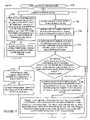
- FIG. 17is a flow chart illustrating the steps of an exemplary method implemented by a base station in one exemplary embodiment.
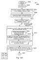
- FIG. 18is a flow chart illustrating the steps of an exemplary method implemented by a wireless terminal in one exemplary embodiment.
- the present inventionis directed to new and novel methods of using superposition coding in a communications systems, e.g., a multi-user communications system.
- Superposition codingoccurs in a downlink and/or an uplink.
- Superposition coding in accordance with the inventionoccurs in the case of the downlink by transmissions to different wireless terminals from a base station using the same communications resource, e.g., simultaneously with the same frequencies.
- Superposition coding in accordance with the inventionoccurs in the case of the uplink by transmissions from different wireless terminals to a base station using the same communications resource.
- the signalscombine in the communications channel resulting in one transmission being superimposed on the other transmission.
- the devicee.g., base station
- receiving the superimposed signalsuses superposition decoding techniques to recover both signals.
- assignments of channel segments to multiple wireless terminalsis controlled by the base station.
- the transmission power levelsare controlled by the base station so that the received power levels are very different to facilitate superposition decoding.
- the transmission power levelsare controlled by the wireless terminals sharing the same uplink communications resource, e.g., time slot, to make sure that the received signals from the different devices at the base station will have different received power levels facilitating superposition decoding.
- FIG. 3illustrates an exemplary wireless communications system 300 implemented in accordance with and using the methods of the present invention.
- Exemplary wireless communications system 300opportunistically uses controlled superposition coding methods on uplink channels and downlink channels in accordance with the present invention.
- Exemplary wireless communications system 300is a spread spectrum OFDM (orthogonal frequency division multiplexing) multiple-access system. While an exemplary OFDM wireless communications system is used in this application for purposes of explaining the invention, the invention is broader in scope than the example, and the invention can be applied in many other communication systems, e.g. a CDMA wireless communications system, as well where controlled superposition coding is employed.
- System 300includes a plurality of cells: cell 1 302 , cell M 304 .
- Each cellincludes a base station (BS), (BS 1 306 , BS M 308 ), respectively, and represents the wireless coverage area of the base station.
- BS 1 306is coupled to a plurality of end nodes, (EN( 1 ) 310 , EN(X) 312 ) via wireless links ( 314 , 316 ), respectively.
- BS M 308is coupled to a plurality of end nodes, (EN( 1 ′) 318 , EN(X′) 320 ) via wireless links ( 322 , 324 ), respectively.
- the end nodes 310 , 312 , 318 , 320may be mobile and/or stationary wireless communications devices and are referred to as wireless terminals (WTs).
- WTswireless terminals
- MNsmobile nodes
- MNsmay move throughout system 300 .
- BS 1 306 and BS M 308are coupled to network node 326 via network links 328 , 330 , respectively.
- Network node 326is coupled to other network nodes and the Internet via network link 332 .
- Network links 328 , 330 , 332may be, e.g., fiber optic cables.
- FIG. 4is an illustration of an exemplary base station 400 implemented in accordance with the invention.
- Exemplary base station 400may be a more detailed representation of any of the base stations 306 , 308 of FIG. 3 .
- Base station 400includes a receiver 402 , a transmitter 406 , a processor 410 , an I/O interface 412 , and a memory 414 coupled together via bus 416 over which the various elements may interchange data and information.
- the receiver 402is coupled to an antenna 404 through which base station 400 may receive uplink signals from a plurality of wireless terminals (WTs) 500 (See FIG. 5 ).
- WTswireless terminals
- Such uplink signalsmay include uplink traffic signals transmitted by different wireless terminals 500 on the same traffic segment which may superpose in the air and/or acknowledgment signals transmitted by different wireless terminals on the same acknowledgement segment which may superpose in the air, in accordance with the invention.
- Receiver 402includes a plurality of demodulation modules, demodulation module 1 418 , demodulation module N 420 .
- the demodulation modules 418 , 420may be part of a decoder module.
- the demodulation modules 418 , 420are coupled together.
- Demodulation module 1 418may perform a first demodulation on a received superposed signal recovering a high power or highly protected signal. The demodulated information may be forwarded from demodulation module 1 418 to demodulation module N 420 . Demodulation module N 420 may remove the high power or highly protected signal from the received superposed signal, and then demodulate the low power or less protected signal.
- separate receivers 402 and/or separate antennas 404may be used, e.g., a first receiver for the high (received) power or highly protected uplink signals and a second receiver for the low (received) power or low protection uplink signals.
- Transmitter 406is coupled to an antenna 408 through which base station 400 may transmit downlink signals to a plurality of wireless terminals 500 .
- Such downlink signalsmay include superposed signals, e.g., a composite of two or more signals on the same channel segment, each signal of the composite at a different transmission power level, and each signal intended for a different wireless terminal.
- Superposed downlink signalsmay be opportunistically transmitted on assignment segments, on downlink traffic signals, and/or on acknowledgement segments, in accordance with the invention.
- Transmitter 406includes a plurality of modulation modules, modulation module 1 422 , modulation module N 424 , and a superposition module 426 .
- Modulation module 1 422may modulate a first set of information, e.g., into a high power or highly protected signal, and modulation module N 424 may modulate a second set of information into a low power or low protection signal.
- Superposition module 426combines the high power or highly protected signal with the low power or low protection signal such that a composite signal may be generated and transmitted on the same downlink segment.
- multiple transmitters 406 and/or multiple antennas 408may be used, e.g., a first transmitter for the high powered or highly protected downlink signals and a second transmitter for the low powered or low protection downlink signals.
- I/O interface 412is an interface providing connectivity of the base station 400 to other network nodes, e.g., other base stations, AAA server nodes, etc., and to the Internet.
- Memory 414includes routines 428 and data/information 430 .
- Processor 410e.g., a CPU, executes the routines 428 and uses the data/information 430 in memory 414 to operate the base station 400 in accordance with the methods of the present invention.
- Routines 428include communications routines 432 and base station control routines 434 .
- Base station control routines 434include a scheduler module 436 , wireless terminal power control routines 438 , transmit power control routines 440 , and signaling routines 442 .
- Scheduler 436includes a downlink scheduling module 446 , an uplink scheduling module 448 , and a relative user strength matching module 450 .
- WT transmit power control routine 438includes a received power target module 452 .
- Data/Information 430includes data 454 , wireless terminal data/information 456 , system information 458 , downlink assignment messages 460 , downlink traffic channel messages 462 , received acknowledgement messages 464 , uplink assignment messages 466 , uplink traffic channel messages 468 , and acknowledgement messages for uplink traffic 470 .
- Data 454includes user data, e.g., data received from WTs over wireless links, data received from other network nodes, data to be transmitted to WTs, and data to be transmitted to other network nodes.
- Wireless terminal data/information 456includes a plurality of WTs information, WT 1 information 472 , WT N information 474 .
- WT 1 information 472includes data 476 , terminal identification (ID) information 478 , received channel quality report information 480 , segment information 482 , and mode information 483 .
- Data 476includes user data received by BS 400 from WT 1 intended for a peer node of WT 1 , e.g., WT N, and user data intended to be transmitted from BS 400 to WT 1 .
- Terminal ID information 478includes a base station assigned ID used to identify WT 1 in communications and operations with BS 400 .
- Received channel quality report information 480includes downlink channel quality feedback information such as, e.g., SNR (signal-to-noise-ratio), SIR (signal-to-interference-ratio).
- Mode information 483includes information indicating the current mode of WT 1 , e.g., on state, sleep state, etc.
- Segment information 482includes a plurality of segment information sets corresponding to channel segments assigned to WT 1 , segment 1 information 484 , segment N information 486 .
- Segment 1 information 484includes segment type information 488 , segment ID information 490 , coding information 492 , and relative strength designation information 494 .
- Segment type information 488includes information identifying the segment's type, e.g., assignment segment for uplink traffic, assignment segment for downlink traffic, uplink traffic channel segment, downlink traffic channel segment, acknowledgment channel segment corresponding to an uplink traffic channel segment, acknowledgement segment corresponding to a downlink traffic channel segment.
- Segment identification (ID) information 490includes information used in identifying the segment, e.g., information used in identifying the frequencies, time, duration, and/or size associated with the segment.
- Coding information 492includes information identifying the type of coding and/or modulation used for the segment.
- Relative strength designation information 494includes information indicating the designated WT relative strength for the purposes of communication on this segment. In some embodiments, the relative strength designation information 494 includes information identifying the WT as either a weak or strong WT for the purposes of communications on this segment.
- System information 458includes tone information 495 , modulation information 496 , timing information 497 , transmission power model information 498 , and received power target model information 499 .
- Tone information 495includes information identifying tones used in hopping sequences, channels, and/or segments.
- Modulation information 496includes information used by BS 400 to implement the various modulation and/or coding schemes, e.g., coding rate information, modulation type information, error correction code information, etc.
- Timing information 497may include timing information used for hopping sequences, superslots, dwells, durations of channel segments, and timing relationships between different types of channel segments, e.g., a timing relationship between an assignment segment, a traffic channel segment, and an acknowledgment channel segment.
- Transmission power model information 498may include information defining models distinguishing transmission power levels of a strong signal and a transmission power level of a weak signal, wherein the two signals are transmitted on the same channel segment as a combined superposed signal, in accordance with the invention.
- Received power model target information 499may include information such as look-up tables used to define models for controlling the WT transmit power to transmit at an appropriate power level in order to achieve a received power target at BS 400 for an uplink channel segment signal.
- a received power model target for a wireless terminalis a function of coding rate and classification of the user (wireless terminal) as a strong or weak user (wireless terminal).
- the received power targetsmay be very different between the strong and weak classification, e.g., a value >3 dB such as 10 dB.
- Downlink assignment messages 460include assignment messages used to notify a WT terminal that it has been assigned a downlink traffic channel segment. Downlink assignment messages 460 are transmitted by BS 400 to WTs on downlink assignment channel segments. In accordance with the invention, multiple downlink assignment messages may be transmitted to multiple WTs on the same assignment segment using controlled superposition coding. Downlink traffic messages 462 include data and information, e.g., user data, transmitted from BS 400 to WTs on downlink traffic channel segments. In accordance with the invention, downlink traffic channel messages 462 may be transmitted to multiple WTs on the same assignment segment using controlled superposition coding.
- Received acknowledgement messages 464include acknowledgement signals from WTs to BS 400 indicating whether or not a WT has successfully received data/information on an assigned downlink traffic channel segment.
- acknowledgement messages 464may have been transmitted by multiple WTs, e.g., with very different received power target levels, to BS 400 on the same assignment segment and the signals may have superposed in the air link.
- Uplink assignment messages 466include assignment messages used to notify a WT terminal that it has been assigned an uplink traffic segment. Uplink assignment messages 466 are transmitted by BS 400 to WTs on downlink assignment channel segments used for assigning uplink channel segments. In accordance with the invention, multiple uplink assignment messages may be transmitted to multiple WTs on the same assignment segment using controlled superposition coding. Uplink traffic channel messages 468 include data and information, e.g., user data, transmitted from WTs to BS 400 on uplink traffic channel segments. In accordance with the invention, uplink traffic channel messages 468 may be transmitted by multiple WTs, e.g., with very different received power target levels, to BS 400 on the same assignment segment and the signals may superpose over the air link.
- Acknowledgement messages for uplink traffic 470include acknowledgement signals to be transmitted from BS 400 to WTs indicating whether or not BS 400 has successfully received data/information on an assigned uplink traffic channel segment.
- multiple acknowledgement messages for uplink traffic 470may be transmitted to multiple WTs on the same acknowledgement segment using controlled superposition coding.
- Communications routines 432is used for controlling base station 400 to perform various communications operations and implement various communications protocols.
- Base station control routine 434is used to control the base station 400 operations, e.g., I/O interface control, receiver 402 control, transmitter 406 control, and to implement the steps of the method of the present invention.
- the scheduler module 436is used to control transmission scheduling and/or communication resource allocation.
- the scheduler module 436may serve as a scheduler.
- the downlink scheduling module 446schedules WTs to downlink channel segments, e.g., downlink traffic channel segments.
- Downlink scheduling module 446may opportunistically schedule multiple WTs to the same downlink segment, e.g., the same downlink traffic channel segment.
- the uplink scheduling module 448schedules WTs to uplink channel segments, e.g., uplink traffic channel segments.
- the uplink scheduling module 448may opportunistically schedule multiple WTs to the same uplink segment, e.g., the same uplink traffic channel segment.
- the opportunistic scheduling and classification of multiple users as weaker/stronger on some corresponding downlink and uplink segmentsmay be interrelated and follow predetermined methods known to both base station 400 and WTs 500 .
- Relative user strength matching module 450may use the received channel quality report information 480 from multiple WTs to classify users with respect to each other on a relative basis as weaker/stronger and to match users, e.g., one relative weaker with one relative stronger, for concurrent scheduling on a given channel segment.
- the relative strength matching routine 450may use other criteria in addition to or in place of the channel quality report information 480 to determine WT matching. For example, some WTs in the population of wireless terminals, e.g., low cost devices, may not have the appropriate demodulation and/or decoding capability to decode a weak signal superposed with a strong signal, and thus should not be scheduled as a strong receiver. Other WTs in the population, e.g., stationary wireless devices with less stringent size and power constraints, may be good candidates for decoding weak signals superposed on strong signals, and thus can be a good choice for scheduling as a strong receiver.
- WT power control routine 438controls the transmission power levels of the WTs operating within BS 400 's cell.
- Received power target module 452uses the data/information 430 including the received power target model information 499 , the coding information 492 , and the relative strength designation information 494 to determine a received power target for uplink signals on uplink segments.
- Transmit power control routine 440uses the data/information 430 including the transmission power model information 498 , coding info 492 , and relative strength designation information 494 to control the transmitter 406 to transmit downlink signals at the appropriate assigned strength for the given segment.
- Signaling routines 442may be used by receiver 402 , transmitter 406 , and I/O interface 412 to control the generation, modulation, coding ,transmission, reception, demodulation, and/or decoding of communicated signals.
- FIG. 5is an illustration of an exemplary wireless terminal 500 implemented in accordance with the invention.
- Exemplary wireless terminal 500may be a more detailed representation of any of end nodes 310 , 312 , 318 , 320 of FIG. 3 .
- Wireless terminal 500may be a stationary or mobile wireless terminal. Mobile wireless terminals are sometimes referred to as mobile nodes and may move throughout the system.
- Wireless terminal 500includes a receiver 502 , a transmitter 504 , a processor 506 , and a memory 508 coupled together via bus 510 over which the various elements may interchange data and information.
- the receiver 502is coupled to an antenna 511 through which wireless terminal 500 may receive downlink signals from a base station 400 .
- Such downlink signalsmay include controlled superposed assignments signals, controlled superposed downlink traffic signals, and/or controlled superposed acknowledgement signals transmitted by base station 400 in accordance with the invention.
- Receiver 502includes a plurality of demodulation modules, demodulation module 1 512 , demodulation module N 514 .
- the demodulation modules 512 , 514may be part of a decoder module(s).
- the demodulation modules 512 , 514are coupled together.
- Demodulation module 1 512may perform a first demodulation on a received superposed signal recovering a high power or highly protected signal.
- the demodulated informationmay be forwarded from demodulation module 1 512 to demodulation module N 514 .
- Demodulation module N 514may remove the high power or highly protected signal from the received superposed signal, and then demodulate the low power or less protected signal.
- separate receivers 502 and/or separate antennas 511may be used, e.g., a first receiver for the high power or highly protected downlink signal recovery and a second receiver for the low power or low protection downlink signal recovery.
- Transmitter 504is coupled to an antenna 515 through which wireless terminal 500 may transmit uplink signals to a base station 400 .
- Such uplink signalsmay include uplink traffic channel signals and acknowledgements signals.
- Transmitter 505includes a modulation module 516 .
- Modulation module 506may modulate data/information into uplink signals.
- the modulation module 506may be part of an encoder module.
- the transmitter 504may be controlled in terms of output power and/or modulation to output uplink signals with different levels of target received power and/or different relative levels of protection, e.g., high targeted received power signals (or highly protected signals) and low targeted received power signals (or less protected signals) for different uplink channel segments in accordance with the invention.
- Memory 508includes routines 518 and data/information 520 .
- Routines 518include communications routine 522 and wireless terminal control routines 524 .
- Wireless terminal control routines 524include signaling routines 526 and channel quality measurement module 528 .
- Signaling routines 526include a receiver control module 530 and a transmitter control module 532 .
- Receiver control module 530includes a plurality of signal detection modules, first signal detection module 534 , Nth signal detection module 536 .
- Transmitter control module 532includes a signal generation module 538 and a transmitter power control module 539 .
- Data/Information 520includes data 540 , terminal identification (ID) information 542 , segment information 544 , mode information 546 , channel quality information 548 , tone information 550 , modulation information 552 , timing information 554 , transmission power model information 556 , received power target model information, received downlink assignment messages 560 , received downlink traffic channel messages 562 , acknowledgement messages for downlink traffic 564 , uplink assignment messages 566 , uplink traffic channel messages 568 , and received acknowledgement messages for uplink traffic 570 .
- IDterminal identification
- Data 540includes user data, e.g., data from a communication peer of WT 500 routed through BS 400 and received in downlink signals from BS 400 .
- Data 540also includes user data to be transmitted in uplink signals to BS 400 intended for peer nodes of WT 500 , e.g., another WT in a communications session with WT 500 .
- Terminal ID information 542includes a base station assigned ID used to identify WT 500 in communications and operations with BS 400 .
- Segment information 544includes a plurality of communication channel segment information sets corresponding to channel segments assigned to WT 500 , segment 1 information 574 , segment N information 576 .
- Segment 1 information 574includes segment type information 578 , segment identification (ID) information 580 , coding information 582 , and relative strength designation information 584 .
- Segment 1 information 574includes segment type information 578 , segment ID information 580 , coding information 582 , and relative strength designation information 584 .
- Segment type information 578includes information identifying the segment's type, e.g., assignment segment for uplink traffic, assignment segment for downlink traffic, uplink traffic channel segment, downlink traffic channel segment, acknowledgment channel segment corresponding to an uplink traffic channel segment, acknowledgement segment corresponding to a downlink traffic channel segment.
- Segment identification information 580may include information used in identifying the segment, e.g., information used in identifying the frequencies, time, duration and/or size associated with the segment.
- Coding information 582includes information identifying the type of coding and/or modulation used for the segment.
- Relative strength designation information 584includes information indicating the designated WT relative strength for the purposes of communication on this segment. In some embodiments, the relative strength designation information 584 includes information identifying the WT as either a weak or strong WT for the purposes of communications on this segment.
- Channel quality report information 548includes downlink channel quality information such as, e.g., SNR (signal-to-noise-ratio), SIR (signal-to-interference-ratio).
- Channel quality report information 548may be obtained from measurements of downlink signals received from BS 400 , e.g., measurements of pilot signals and/or beacon signals.
- Channel quality report information 548is fed back to BS 400 and is used by the BS 400 in making decisions regarding opportunistically matching and scheduling users as relative weaker/stronger WTs on the same segment, in accordance with the invention.
- Mode information 546includes information indicating the current mode of WT 1 , e.g., on state, sleep state, etc.
- Tone information 550includes information identifying tones used in hopping sequences, channels, and/or segments.
- Modulation information 552includes information used by WT 500 to implement the various modulation and/or coding schemes, e.g., coding rate information, modulation type information, error correction code information, etc.
- Timing information 554may include timing information used for hopping sequences, superslots, dwells, durations of channel segments, and timing relationships between different types of channel segments, e.g., a timing relationship between an assignment segment, a corresponding traffic channel segment, and a corresponding acknowledgment channel segment.
- Received power model target information 558may include information such as look-up tables used to define models for controlling the WT transmit power to transmit at an appropriate power level in order to achieve a received power target at BS 400 for an uplink channel segment signal.
- a received power model target for wireless terminal 500is a function of coding rate and classification of the user (wireless terminal) as a strong or weak user (wireless terminal).
- the received power targetsmay be very different between the strong and weak classification, e.g., a value >3 dB such as 10 dB.
- Received downlink assignment messages 560include received assignment messages from BS 400 used to notify WT terminal 500 that it has been assigned a downlink traffic segment. Downlink assignment messages are transmitted by BS 400 to WT 500 on downlink assignment channel segments. In accordance with the invention, a received downlink assignment message 560 may be one of multiple downlink assignment messages transmitted to multiple WTs on the same assignment segment using controlled superposition coding. Received downlink traffic messages 562 include data and information, e.g., user data, transmitted from BS 400 to WTs on downlink traffic channel segments. In accordance with the invention, a received downlink traffic channel message 562 may be one multiple downlink traffic messages transmitted to multiple WTs on the same assignment segment using controlled superposition coding.
- Acknowledgement messages for downlink traffic 564include acknowledgement messages to be transmitted by WT 500 to BS 400 indicating whether or not WT 500 has successfully received data/information on an assigned downlink traffic channel segment.
- acknowledgement messages 564may be transmitted, with a controlled received power target, by WT 500 to BS 400 on the same assignment segment used by other WTs.
- Received uplink assignment messages 566include assignment messages used to notify WT 500 that it has been assigned an uplink traffic segment. Received uplink assignment messages 566 are obtained from received signals of BS 400 transmissions to WT 500 on downlink channel segments used for assigning uplink channel segments. In accordance with the invention, a received uplink assignment message 566 may be one of multiple uplink assignment messages transmitted by BS 400 to multiple WTs on the same assignment segment as part of a controlled superposed signal in accordance with the invention.
- Uplink traffic channel messages 568include data and information, e.g., user data, transmitted from WT 500 to BS 400 on uplink traffic channel segments.
- uplink traffic channel messages 568may be transmitted, with a controlled received power target, by WT 500 to BS 400 on the same assignment segment as other WTs are transmitting uplink traffic channel messages and the signals from multiple WTs may superpose over the air link.
- Acknowledgement messages for uplink traffic 570include acknowledgement signals from BS 400 to WTs indicating whether or not BS 400 has successfully received data/information on an assigned uplink traffic channel segment.
- base station 400may transmit multiple acknowledgement messages to multiple WTs in a combined controlled superposed signal on the acknowledgment segment.
- Communications routine 522is used for controlling wireless terminal 500 to perform various communications operations and implement various communications protocols.
- Wireless terminal control routines 524is used to control the wireless terminal 500 operations, e.g., receiver 502 control, transmitter 504 control, and to implement the steps of the method of the present invention.
- Signaling routines 526include a receiver control module 530 used for control related to downlink signaling and a transmitter control module 532 used for control related to uplink signaling.
- Receiver control module 530directs the operation of receiver 502 to receiver, demodulate, and/or decode downlink signals from base station 400 including superposed signals.
- First signal detection module 534uses the data/information 520 including modulation information 552 and segment information 544 to control demodulation module 1 512 to receive and process signals, e.g., recovering a high power or high protection signal from a superposed downlink signal.
- Nth. signal detection module 536uses the data/information 520 including modulation information 552 and segment information 544 to receive and process signals, e.g., recovering a low power or low protection signal from a superposed downlink signal.
- Transmitter control module 532directs the operation of transmitter 504 and its modulation module 516 for operations related to uplink signaling such as signal generation and power control.
- Signal generation module 538uses data/information 520 including modulation information 552 and segment information 544 to generate uplink signals from uplink information to be communicated, such as, e.g., uplink traffic channel messages 568 .
- Transmitter power control module 539uses data/information 520 including received power target model information 558 and segment information 544 such as coding information 582 and relative strength designation information 584 to control the transmitter to regulate the uplink signal strength for uplink segments, e.g., individual uplink segments.
- the transmitter power control module 539may adjust transmission power levels for individual segments to attempt to reach a received power target level at the base station 400 , in accordance with the invention.
- This control of wireless terminal transmission power with respect to expected received power at a base stationallows for the base station 400 to opportunistically schedule multiple wireless terminals on the same uplink segment with different received power targets, to receive an uplink signal including superposed signals from multiple wireless terminals, and to extract the individual signals from each wireless terminal.
- Channel quality measurement module 528performs measurements of received signals, e.g., pilot signals and/or beacon signals, to obtain channel quality information 548 .
- the air link resourcegenerally includes bandwidth, time and/or code.
- the air link resource that transports data and/or voice trafficis called the traffic channel.
- Datais communicated over the traffic channel in traffic channel segments (traffic segments for short). Traffic segments may serve as the basic or minimum units of the available traffic channel resources.
- Traffic segmentsmay serve as the basic or minimum units of the available traffic channel resources.
- Downlink traffic segmentstransport data traffic from the base station to the wireless terminals, while uplink traffic segments transport data traffic from the wireless terminals to the base station.
- One exemplary system in which the present invention is usedis the spread spectrum OFDM (orthogonal frequency division multiplexing) multiple-access system in which a traffic segment includes of a number of frequency tones over a finite time interval.
- the traffic segmentsare dynamically shared among the wireless terminals that are communicating with the base station.
- a scheduling functione.g., module in the base station may assign each uplink and downlink segment to one or more of the wireless terminals, e.g., mobile terminals, based on a number of criteria.
- FIG. 6is a diagram 600 of frequency on vertical axis 602 vs time on horizontal axis 604 and illustrates exemplary traffic segments.
- Traffic segment A 606is indicated by the rectangle with vertical line shading
- traffic segment B 608is indicated by the rectangle with horizontal line shading.
- traffic segments A 606 and B 608occupy the same frequencies but occupy different time intervals.
- segment A 606is assigned to user #1 by the base station's scheduler and segment B 608 is assigned to user #2.
- the base station's schedulercan rapidly assign the traffic channel segments to different users according to their traffic needs and channel conditions, which may be time varying in general. The traffic channel is thus effectively shared and dynamically allocated among different users on a segment-by-segment basis.
- the assignment information of traffic channel segmentsis transported in the assignment channel, which includes a series of assignment segments.
- assignment segmentsare generally transmitted in the downlink.
- Each traffic segmentmay be, and generally is, associated with a unique assignment segment.
- the associated assignment segmentconveys the assignment information of the corresponding traffic segment.
- the assignment informationmay include the identifier of the user terminal(s), which is assigned to utilize that traffic segment, the coding and/or modulation scheme to be used in that traffic segment.
- FIG. 7is a diagram 700 illustrating exemplary assignment and traffic segments.
- FIG. 7shows frequency on vertical axis 702 vs time on horizontal axis 704 .
- the assignment segment 7includes two assignment segments, A′ 706 and B′ 708 , and two traffic segments, traffic segment A 710 and traffic segment B 712 .
- the exemplary assignment segments 706 , 708occupy the same frequencies but occupy different time intervals.
- the exemplary traffic segments 710 , 712occupy the same frequencies but occupy different time intervals.
- the assignments segments 706 , 708occupy different frequencies than the traffic segments 710 , 712 .
- Assignment segment A′ 706conveys the assignment information of traffic segment A 710 as indicated by arrow 714 .
- Assignment segment B′ 710conveys the assignment information for traffic segment B 712 as indicated by arrow 716 .
- Each assignment segment 706 , 708precedes its respective traffic segment 710 , 712 .
- the assignment channelis a shared channel resource. The users receive the assignment information conveyed in the assignment channel and then utilize the traffic channel segments according to the assignment information.
- Data transmitted by the base station on a downlink traffic segmentis decoded by a receiver in the intended wireless terminal while data transmitted by the assigned wireless terminal on the uplink segment is decoded by a receiver in the base station.
- the transmitted segmentincludes redundant bits that help the receiver determine if the data is decoded correctly. This is done because the wireless channel may be unreliable and data traffic, to be useful, typically has high integrity requirements.
- the transmission of a traffic segmentmay succeed or fail.
- the receiver of a traffic segmentsends an acknowledgment to indicate whether the segment has been received correctly.
- the acknowledgment information corresponding to traffic channel segmentsis transported in the acknowledgment channel, which includes a series of acknowledgment segments.
- Each traffic segmentis associated with a unique acknowledgment segment.
- the acknowledgment segmentis in the uplink.
- the acknowledgment segmentis in the downlink.
- the acknowledgment segmentcan convey one-bit of information, e.g., a bit, indicating whether the associated traffic segment has been received correctly or not.
- FIG. 8includes a diagram 800 showing exemplary downlink traffic channel segments and a graph 850 showing exemplary uplink acknowledgement segments.
- Diagram 800plots frequency on vertical axis 802 vs time on horizontal axis 804 .
- Diagram 800includes downlink traffic segment A 806 illustrated by vertical line shading and downlink traffic segment B illustrated by horizontal line shading. Each traffic segment 806 , 808 occupies the same frequencies but a different time slot.
- Graph 850plots frequency on vertical axis 852 vs time on horizontal axis 854 .
- Graph 850includes uplink acknowledgement segment A′′ 856 and uplink acknowledgement segment B′′ 858 . Each acknowledgement segment 856 , 858 occupies the same frequencies but a different time slot.
- the two uplink acknowledgment segments, A′′ 856 and B′′ 858convey the acknowledgment information of downlink traffic segments A 806 and B 808 , respectively.
- the linkage between traffic segments A 806 to acknowledgement segment A′′ 856is indicated by arrow 860 ; the linkage between traffic segment B 808 and acknowledgement segment B′′ 858 is indicated by arrow 862 .
- This inventionrealizes the benefits of superposition coding in a multi-user communication system while using simple receiver design in both the broadcast channel and the multiple-access channel.
- the advantages of using superposition codingare greater in systems where there is a large dynamic range in the channel quality experienced by different users.
- wireless communication systemsit is common to find the channel quality varying by as much as 30 dB or even higher (three orders of magnitude) among various users.
- the advantages conferred by this inventioncontribute significantly to enhanced system capacity in such systems.
- Superposition codingin accordance with the present invention, in the context of the downlink (broadcast) channel shall now be described.
- the transmitter of this downlink (broadcast) channelis the base station and the receivers are mobile or fixed wireless user terminals, e.g., sometimes referred to as mobile users or users, served by the base station.
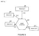
- An example of such a systemis illustrated in exemplary system 900 of FIG.
- a base station 902is communicating on the downlink as well as the uplink with four mobile users, mobile user 1 904 , mobile user 2 906 , mobile user 3 908 , mobile user 4 910 via wireless links 912 , 914 , 916 , 918 , respectively.
- the mobile users 904 , 906 , 908 , 910are at different distances from the base station 902 and consequently may experience different channel conditions.
- the users 904 , 906 , 908 , 910frequently update the base station 902 with a measure of the downlink channel quality and interference condition they currently experience.
- the base station 902typically uses this information to schedule users for transmission and allocates the downlink channel resources to them.
- the base station 902can use the channel quality and interference condition report to allocate transmission power to different users 904 , 906 , 908 , 910 on the broadcast channel.
- Userse.g. mobile user 2 906 and mobile user 4 910 who are closer to the base station 902 are generally allocated smaller amounts of power while users, e.g., mobile user 1 904 and mobile user 3 908 , who are located farther away from the base station 902 are allocated large amounts of power.
- Bandwidthcan be allocated appropriately to different users 904 , 906 , 908 , 910 based on the channel conditions.
- the most commonly used metric of channel qualityis the receive signal-to-noise ratio (SNR), while other similar or equivalent metrics can be used.
- SNRreceive signal-to-noise ratio
- the base station schedulercan select two or more user terminals to be scheduled on the same traffic segment.
- the selected terminalsshould preferably have SNRs that span a wide dynamic range.
- Superposition codingis then used to send data to the selected terminals on the same traffic segment. It should be pointed out here that practically speaking, the advantages of using superposition coding may be realizable by scheduling two appropriately selected users on a given traffic segment although, in some embodiments, larger numbers of users may be scheduled. Scheduling a small number of users, e.g., two, has the advantage of resulting in a significantly less decoding effort at user terminals compared to the case when a larger number of users (>2) are scheduled on the same traffic segment.
- the base stationis not always required to use superposition coding, but can do so in an opportunistic manner.
- the base stationcan default to the simple state where it transmits to a single user.
- the transmitterwill consider ‘B’ to be a ‘strong user’ and ‘C’ a ‘weak user’ when transmitting to these two users together using superposition coding.
- user ‘A’is considered the strong user, with user B being considered the weak user.
- the userscan derive their current status from the control channel that transmits the assignment information about which users are currently scheduled with high or low power signals.
- the signal intended for the weaker usersis protected more e.g., with better coding or higher power, than the signal intended for stronger users, which are protected less.
- the receiver of the uplink (multiple-access) channelis the base station and the transmitters are the user terminals served by the base station.
- the multiple-access channelis divided among the users in time or code space or frequency.
- the channelmay be shared among multiple users, with their signals interfering with each other at the base station receiver.
- a CDMA systemis an example of a system where the channel may be shared among multiple users.
- the user signalscan be separated using joint detection (also known as multi-user detection) techniques. In practice, however, this is quite complex.
- the base station schedulercan select two or more user terminals to transmit uplink data on the same traffic segment resource.
- the signals from the selected terminalsare superposed in the transmission medium.
- FIG. 10is a diagram 1000 used for illustrating superposition coding in a multiple-access channel in accordance with the present invention.
- FIG. 10shows different receive power targets of two superposed signals.
- FIG. 10includes an exemplary high power QPSK signal illustrated by the four shows shaded circles 1002 and an exemplary low power QPSK signal 1004 illustrated by the four unshaded circles.
- the strength of the high power signalmay be represented by long arrow 1006 from the origin 1008 to a point 1002 with magnitude ⁇ (1 ⁇ )P, while the strength of the low power signal may be represented by short arrow 1010 from the origin 1008 to a point 1004 with magnitude ⁇ P .
- the base station schedulercan coordinate operations so that the selected user terminal uplink signals are received at different power levels.
- wireless terminals with smaller path lossmay be operated so that their uplink signals are to be received by the base station at a relative higher power
- wireless terminals with larger path lossmay be operated so that their uplink signals are to be received by the station at a relative lower power.
- the schedulercan select user terminals that span a large range of path losses for the same traffic segment.
- the user terminals that cause less out-of-cell interferencemay be operated so that their signals are to be received by the base station at relative higher power, while the user terminals that cause more out-of-cell interference may be operated so that their signals are to be received by the base station at relative lower power.
- the schedulercan select terminals that span a large range in the out-of-cell interference that they create for the same traffic segment.
- a ‘strong’ userin this case refers to a user terminal that is operated to be received at a higher power compared with another ‘weaker’ user transmitting on the same traffic segment.
- a usercan learn whether it should target a higher or lower receive power level, e.g., from a control channel, in which the base station may, and in various embodiments does, instruct the users about the assignment information of the traffic channel.
- the base stationIn the event that the base station is constrained, it can choose not to schedule more than one user terminal on one traffic segment. This choice is completely transparent to the users, which really do not need to do anything different whether superposition is used or not.
- the downlink traffic channelfits within the broadcast communications method regime, while the uplink traffic channel is a typical example of the multiple-access communications method.
- Both the downlink and uplink traffic segmentsare dynamically assigned to the users according to the scheduler decisions made by the base station scheduler.
- the base station scheduleralso determines the coding and modulation rate used in the traffic segment.
- the assignment channelis the control channel that conveys the assignment information to the wireless terminals, e.g., mobile user terminals. This embodiment of the invention is described using two subsystems, one for the downlink broadcast channel, and the other for the uplink multiple-access channel.
- Each mobile user in the systemfrequently updates the base station of its downlink channel condition, e.g., in a channel quality and interference condition feedback report.
- This reportmay include various parameters such as signal-to-noise ratio, channel frequency profile, fading parameters, etc.
- the base stationschedules two or more users and superposes user signals on each downlink traffic segment.
- the base stationalso selects parameters, such as code rates and transmission power, for the superposed signals.
- the scheduler decisions corresponding to a traffic segmentare communicated on the corresponding assignment segment, which is monitored by the users, e.g., wireless terminals.
- the assignment informationcan also be superposition coded on the assignment segment.
- FIG. 11includes two exemplary receivers, a weaker receiver 1102 and a stronger receiver 1104 .
- FIG. 11also includes an assignment segment 1106 and a traffic segment 1108 .
- the base stationtransmits a composite assignment signal with superposition coding 1110 to both receivers 1102 , 1104 .
- the base stationsubsequently transmits a composite traffic signal with superposition coding 1112 to both receivers 1102 , 1104 .
- the assignment information for the weaker receiver 1102is sent as high power signal of the superposition codes on the assignment channel, while the assignment information for the stronger receiver 1104 is sent as the low power signal of the superposition codes on the assignment channel.
- a user 1102 , 1104first decodes the high power signal component of an assignment segment 1106 . If the user is assigned by the high power signal of the assignment segment 1106 , as user 1102 is, then the user knows that it is scheduled as ‘weaker receiver’ and shall also decode the high power signal of the composite signal 1112 of the corresponding traffic channel segment 1108 . Otherwise, the user shall proceed to decode the low power signal of the assignment segment 1106 since it may be considered the stronger receiver.
- the useris assigned by the low power signal of the assignment segment, as receiver 1104 is, then the user knows that it is scheduled as ‘stronger receiver’ and shall proceed to decode the low power signal of the corresponding traffic channel segment 1108 . If the user is not assigned by the low power signal of the assignment segment 1106 , or cannot even decode the low power signal of composite assignment signal 1110 , the user may not be in a position to decode the low power signal of the composite traffic signal 1112 of the traffic segment 1108 and can choose not to attempt to decode it. In the more general case, what has been referred to as the high power signal can be a better protected signal and what has been referred to as the low power signal can be a less protected signal.
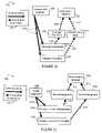
- FIG. 12is a drawing 1200 illustrating superposition coding used in broadcast assignment and multiple-access traffic channels.
- FIG. 12includes a key 1201 illustrating that solid heavy arrows denote downlink signals while heavy dashed arrows denote uplink signals.
- FIG. 12includes a base station receiver 1202 , a first user, e.g. a wireless terminal, designated the weaker transmitter 1204 , and a second user, e.g., a wireless terminal, designated the stronger transmitter 1206 .
- FIG. 12also shows an assignment segment 1208 .
- a downlink composite assignment signal 1210including superposition coding, is transmitted from the base station to the two wireless terminals 1204 , 1206 on the assignment segment 1208 .
- Wireless terminal 1204transmits signal 1214 including weaker user data 1212 to base station receiver 1202
- wireless terminal 1206transmits signal 1216 including stronger user data 1218 to base station receiver 1202 .
- Signals 1212 and 1216are transmitted on the same uplink traffic segment and the signals are superposed over the air.
- the base stationschedules one or more users 1204 , 1206 , who then superpose their signals 1212 , 1216 on a single uplink traffic segment over the air.
- the base stationcan also select parameters, such as code rates and transmission power, for the superposed signals 1212 , 1216 .
- the base stationmakes the scheduling decision with a bias towards users who can be power controlled in a manner such that they are received at different powers at the base station.
- the users that are superposedcan be users that in one embodiment, experience different path losses in the uplink or in another embodiment, users that have quite different uplink out-of-cell interference impact.
- the base stationthen communicates this decision using superposition coding on the assignment channel in downlink composite assignment signal 1210 .
- a usere.g., a mobile wireless terminal, first decodes the high power (better protected) signal of an assignment segment 1208 .
- the userif the user is assigned by the high power signal of the assignment segment 1208 , then the user infers that it is scheduled by the base station as a ‘weaker transmitter’ and shall send on the corresponding uplink traffic segment to be received at lower power.
- user 1204has inferred that it is scheduled by the base station as the weaker transmitter and transmits uplink traffic signal 1212 at a low targeted receive power level.
- the userif the user is in a position to decode the low power (less protected) signal included in composite signal 1212 on the assignment channel 1208 , and finds that it is scheduled, it infers its current state to be a ‘stronger transmitter’. It then proceeds to transmit on the corresponding uplink traffic segment with suitable transmit power such that it is received at higher power.
- user 1206first decodes and removes the weaker user assignment, then decodes the stronger user assignment, finds that it is scheduled, infers that it is the stronger transmitter, and transmits uplink traffic signal 1216 at a high targeted receive power level.
- the usermay not use the corresponding uplink traffic segment as a ‘strong transmitter’.
- the notion of stronger and weaker transmittersmay be defined based on other criteria such as uplink interference cost or device-related constraints.
- superposition codingcan, and is, carried out in an opportunistic manner and need not be carried out on each of the traffic segments. This allows the base station scheduler significant flexibility.
- the low-power signalis sent on the assignment channel when users with divergent channel conditions are found, and the low-power signal is not sent on the assignment channel at other times. Otherwise, if both high and low power signals were transmitted on the same channel segment when divergent channel conditions did not exist, the users may be able to detect the high power signal on the assignment channel but may decode noise when they attempt to decode a potential superposed low-power signal.
- the receiverAfter a traffic segment is received, the receiver generally sends an acknowledgment, in the acknowledgment channel, to inform the transmitter whether the traffic segment has been correctly received.
- an acknowledgmentin the acknowledgment channel, to inform the transmitter whether the traffic segment has been correctly received.
- there is a corresponding uplink acknowledgment segmentfor each downlink traffic segment, there is a corresponding uplink acknowledgment segment, and for each uplink traffic segment, there is a corresponding downlink acknowledgment segment.
- the uplink acknowledgment channelis implemented as a multiple-access channel using multiple access communication methods. From the above framework of controlled superposition coding in the case when multiple-access communications methods are used, the users superpose their acknowledgments on the same acknowledgment segment.
- Drawing 1300 of FIG. 13is used to illustrate superposition coding used in broadcast traffic and superposition coding used in multiple-access acknowledgement channels.
- FIG. 13includes a key 1301 illustrating that solid heavy arrows denote downlink signals while dashed heavy arrows denote uplink signals.
- FIG. 13includes a key 1301 illustrating that solid heavy arrows denote downlink signals while dashed heavy arrows denote uplink signals.
- FIG. 13includes a base station receiver 1302 , a first user 1304 , e.g., a wireless terminal, designated as the weaker receiver/transmitter, a second user 1306 , e.g., a wireless terminal, designated as the stronger receiver/transmitter.
- FIG. 13also includes a downlink traffic segment 1308 and a composite downlink signal 1310 with superposition coding.
- the downlink composite traffic signal 1310is transmitted from the base station to both users 1304 , 1306 on the same downlink traffic segment 1308 .
- FIG. 13also includes an uplink acknowledgment signal 1312 from user 1304 to base station receiver 1302 and an uplink acknowledgement signal 1314 from user 1306 to base station receiver 1302 .
- Signal 1312is transmitted at a low targeted receive power, while signal 1314 is transmitted at a high targeted receive power.
- the uplink acknowledgement signals 1312 and 1314are transmitted on the same acknowledgement segment 1316 and are superimposed over the air.
- FIG. 13shows that two users 1304 , 1306 receive their downlink traffic segment 1308 with superposition coding.
- the two users 1304 , 1306then send their acknowledgments 1312 , 1314 on the same acknowledgment segment 1316 with different target receive power levels.
- the userwho is identified as the stronger receiver of the traffic segment (receives less protected information), is automatically considered the stronger transmitter of the acknowledgment segment, and thus sends its acknowledgment targeting a higher receive power.
- user 1306is identified as the stronger receiver of the traffic segment 1308 and is considered the stronger transmitter.
- User 1306first decodes and removes the better protected signal meant for the weaker user 1304 and then decodes the data intended for user 1306 .
- the userwho is identified as the weaker receiver of the traffic segment, is automatically considered the weaker transmitter of the acknowledgment segment, and thus sends its acknowledgment targeting a lower receive power.
- user 1304is identified as the weaker receiver of the traffic segment 1308 and is considered the weaker transmitter.
- FIG. 14shows exemplary superposition coding used in multiple-access traffic channels and exemplary superposition coding used in broadcast acknowledgement channels.
- FIG. 14includes a key 1401 illustrating that solid heavy arrows denote downlink signals while dashed heavy arrows denote uplink signals.
- a base station receiver/transmitter 1402includes a base station receiver/transmitter 1402 , a first user 1404 , e.g., a wireless terminal, designated the weaker transmitter/receiver, and a second user 1406 , e.g., a wireless terminal, designated the stronger transmitter/receiver.
- User 1404transmits its uplink traffic signal 1408 at a targeted low receive power
- user 1406transmits its uplink traffic signal 1410 at a high targeted receive power.
- FIG. 14shows that two users 1404 , 1406 transmit their uplink traffic signals 1408 , 1410 on the same traffic segment 1412 , and the two signals are superposed over the air.
- the base station 1402then sends two acknowledgments in a composite downlink acknowledgement signal 1416 on the same acknowledgment segment 1414 with different transmit power levels for each acknowledgement.
- the userwho is identified as the stronger transmitter of the traffic segment 1412 , is automatically considered the stronger receiver of the acknowledgment segment 1414 , and thus the base station sends its acknowledgment at low transmit power (less protected).
- user 1406is identified as the stronger transmitter and thus base station 1402 sends the acknowledgement signal for user 1406 at low transmit power.
- User 1406receives signal 1416 and first decodes and removes the better protected signal meant for the weaker user 1404 and then decodes its own acknowledgement signal.
- the userwho is identified as the weaker transmitter of the traffic segment 1408 , is automatically considered the weaker receiver of the acknowledgment segment 1414 , and thus the base station 1402 sends its acknowledgment at high transmit power (more protected).
- user 1404is identified as the weaker transmitter and thus base station 1402 sends the acknowledgement signal for user 1404 at high transmit power.
- controlled superposition codingis used to reduce the transmit power level on common control channels used in multi-user communication systems.
- Common control channelsare often used to send control information to every user in the system. As a result, they are normally transmitted at a high transmit power in order to reach the worst-case user.
- This embodimentwill be described in the context of a cellular wireless communication system, but is applicable more generally.
- This exemplary embodimentassumes a common control channel that is transmitted by the base station on the downlink and monitored by wireless terminal users, e.g., each of mobile users in a cell.
- the control informationis partitioned into two groups.
- the first groupis referred to as ‘regular information’, which is intended for mainstream users.
- the set of mainstream usersare those mobile users with reasonable downlink channel conditions e.g., reasonable downlink SNR.
- the second groupis referred to as ‘protected information’, which is intended to be received by most or all of the mobile users in the system, i.e. not only mainstream users but also weaker users, which have poor downlink SNR.
- the protected control informationis transmitted at high power per bit, which enables it to be received robustly by some or all of the weak users in the system.
- the regular informationis then superposed on the protected information at nominal power per bit.
- the weak usersmay not be able to decode all the information but should be able to decode the protected information from the superposed signal, while the mainstream users will be able to decode both the protected and the regular information.
- FIG. 15is a drawing 1500 illustrating the application of superposition coding to a common control channel.
- FIG. 15includes a first user 1502 , e.g., a wireless terminal, designated the weaker receiver, and a second user 1504 , e.g., a wireless terminal, designated the stronger receiver.
- FIG. 15also includes an assignment segment 1506 , a composite assignment signal with superposition coding 1512 , a downlink traffic segment “A” 1508 , and a downlink traffic segment “B” 1510 .
- Downlink traffic segment “A”is intended for the weaker receiver 1502
- downlink traffic segment “B”is intended for the stronger receiver 1504 .
- the assignment information of those two traffic segmentsis sent in a single assignment segment 1506 with superposition coding. Specifically, the assignment information for segment A is treated as protected information and that for segment B is treated as regular information.
- the mainstream users, e.g., user 1504can decode both assignments and thus be scheduled in any of the traffic segments 1508 , 1510 .
- stronger receiver 1504first decodes and removes the better protected signal meant for the weaker receiver 1502 and then decodes its assignment.
- the weak users, e.g., 1502can only decode the assignment for segment A 1508 and thus be scheduled only in segment A 1508 .
- superposition coding on the assignment channelis not necessarily tied to superposition coding on the corresponding traffic segments in this example.
- Traffic segment “A” and traffic segment “B”are distinct traffic segments and signals 1514 and 1516 are distinct signals and are not superposed.
- Superposition coding on a common control channelis a valuable practical technique in its own right, and may result in power savings as well as increased robustness.
- FIG. 16is a drawing 1600 including exemplary uplink signals on the same uplink channel segment, and is used to illustrate the concept of targeted received power in accordance with an embodiment of the invention.
- FIG. 16includes a two exemplary wireless terminals implemented in accordance with the invention, WT 1 1602 , WT 2 1604 , and an exemplary base station 1606 , implemented in accordance with the invention.
- the channel gain between WT 1 1602 and BS 1606is G 1 1610 and is known to both WT 1 1602 and BS 1606 , e.g., by measurements of pilots signals and a feedback channel quality report.
- the channel gain between WT 2 1604 and BS 1606is G 2 1612 is known to both BS 1606 and WT 2 1604 , e.g., by measurements of pilots signals and a feedback channel quality report. Assume that both WT 1 1602 and WT 2 1604 are transmitting using the same data rate, modulation, coding scheme, and coding rate. WT 1 1602 has been designated as the stronger transmitter by base station 1606 for uplink channel segment 1608 , while WT 2 1604 has been designated as the weaker transmitter by base station 1606 for uplink channel segment 1608 .
- Uplink signal 1614includes the nominal power signal S 1 including WT 1 uplink information and has been scaled by a transmission gain value a 1 .
- Signal 1614is transmitted from WT 1 1602 as a 1 S 1 ; however, due to the channel losses, the signal is received by the base station's receiver as a 1 G 1 S 1 (a reduced level).
- WT 1 1602knows the channel value of G 1 .
- WT 1 1602has pre-adjusted the value of a 1 to achieve a high received power target represented by a 1 G 1 .
- the channel gain between WT 2 1604 and BS 1606is G 2 1612 is known to both BS 1606 and WT 2 1604 , e.g., by measurements of pilots signals and a feedback channel quality report.
- WT 2 1604transmits uplink signal 1616 to the BS 1606 .
- Uplink signal 1616includes nominal power signal S 2 including WT 2 uplink information and has been scaled by a transmission gain value a 2 .
- Signal 1616leaves the WT as a 2 S 2 ; however, due to the channel losses, the signal is received by the base station's receiver as a 2 G 2 S 2 (a reduced level).
- WT 2 1604knows the channel value of G 2 .
- WT 2has pre-adjusted the value of a 2 to achieve a low received power target represented by a 2 G 2 . Since the two signals 1614 and 1616 were transmitted on the same uplink channel segment 1608 , the signals superposed in the air and were received by base station 1606 as a combined signal (a 1 G 1 )S 1 +(a 2 G 2 )S 2 1618 .
- the two received power targetswere chosen such that the high power target, represented by a 1 G 1 is greater, e.g., much greater, than the low power target represented by a 2 G 2 .
- the BScan differentiate between the two signals from the two independent devices (WT 1 1602 , WT 2 1604 ) and extract the information from signals S 1 and S 2 . Note that a 1 can be less than a 2 depending upon the channel gains.
- FIG. 17is a flowchart 1700 of an exemplary method of operating a base station (BS) in accordance with the present invention.
- the exemplary method of flowchart 1700uses controlled superposition in accordance with the present invention.
- base station operationstarts, e.g., the base station is powered on and initialized. Operation proceeds from step 1702 to step 1704 .
- the BSmonitors to receive signals, e.g., uplink signals from WTs. Operation proceeds from step 1704 to steps 1706 and 1722 .
- the BSreceives channel quality reports from a plurality of WTs.
- the BSmaintains a set of channel condition information indicating the channel quality of each of a plurality of WTs.
- the maintained set of channel condition informationincludes, e.g., separate channel signal to noise ratio information for each of the plurality of WTs. Operation proceeds from step 1708 to step 1710 .
- the BSexamines the set of channel condition information to identify WTs having channel conditions which differ from one another by at least a pre-selected minimum amount, e.g., 3 dB or 5 dB or 10 dB. Then, in step 1712 , the BS determines if there are at least two WTs identified as having channel conditions which differ by at least the pre-selected minimum amount, that have signals to be transmitted in a communications channel segment which is available to be assigned.
- step 1714the BS assigns a communications channel segment to be used to communicate superimposed signals corresponding to at least two different WTs identified as having channel conditions which differ by at least the pre-selected minimum amount, e.g., a first WT which has a better channel quality (by at least the pre-selected minimum amount) than a second WT.
- the assigned communication channel segmentmay be, e.g., a downlink channel segment that is an assignment channel segment used to communicate uplink communications channel segment assignments, e.g, uplink traffic channel segment assignments, to WTs.
- step 1716the base station transmits a superimposed signal to the two different identified WTs, the first WT, and the second WT, e.g., an assignment channel segment corresponding to the communications channel segment being assigned, said superimposed signal including a low power signal portion intended for said first WT and a high power signal portion intended for said second wireless terminal, the lower power signal portion being transmitted by said BS with lower power than said high power signal portion.
- step 1704the base station monitors for additional signals.
- step 1712If it is determined in step 1712 , that there are not at least two WTs identified having channel conditions which differ by at least the pre-selected minimum amount having signals to be transmitted in a communications channel segment which is available to be assigned, then operation proceeds to step 1718 .
- the BSassigns the available communications channel segment to a single one of said plurality of WTs. Operation proceeds from step 1718 to step 1720 .
- step 1720the base station transmits an assignment signal to said single one WT. Operation proceeds from step 1720 to step 1704 , in which the BS continues to monitor for signals.
- step 1722the base station receives a superimposed signal from said first and second WTs, said superimposed signal including first and second signal portions transmitted by said first and second WTs, respectively, said first signal portion being received by said BS at a higher power level than said second signal portion. Operation proceeds from step 1722 to step 1724 . In step 1724 , the BS decodes first signal portion; subtracts the first signal portion from the said superimposed signal; and then decodes said second signal portion. Operation proceeds from step 1724 to step 1704 , in which the base station continues to monitor to receive signals.
- FIG. 18illustrates the steps performed by a WT in accordance with one exemplary embodiment of the invention where superimposed uplink channel assignment messages are used to assign uplink traffic channel segments to WTs.
- the assignment message intended for a particular WTincludes the WT's particular terminal identifier.
- the transmission of the assignment message (e.g., terminal ID) to the WT with the better channel conditionis on the low power portion of the superimposed assignment message signal while the assignment to the WT with the poorer channel condition is on the high power portion of the superimposed assignment message signal.
- the method 1800begins in start step 1802 .
- the WTis initialized, e.g., as part of a power on operation.
- the WTperiodically measures the channel conditions and reports the channel conditions to the BS with which it is interacting.
- the WTreceives transmission power control adjustment information from the BS in step 1808 on a periodic basis. Based on this information the WT can predict what the received power will be at the BS for a particular transmission power level.
- the BS power control informationallows the WT to determine a transmission power level required to meet a target received power level.
- the WTstores information, e.g., a table including different gain coefficients that can be used to achieve different received power levels, which can be used in combination with the WT feedback information which indicates the transmission power required to achieve a particular reference level.
- the gain coefficientscan be used as offsets from the gain required to achieve the particular reference level thereby resulting in the received power level associated with the gain coefficient when used to adjust the transmission power level in combination with the received power control feedback information.
- Step 1810Monitoring for channel assignment messages occurs in step 1810 .
- Steps 1806 , 1808 and 1810are performed on an ongoing basis while the WT operates in an active state.
- For each assignment message received in step 1810 operationproceeds to step 1812 .
- a superposition decoding operationis performed on the received assignment message which is a superimposed signal including a first signal part and a second signal part where the first and second signal parts are transmitted at different power levels with the first signal part being the higher power part.
- the decoding step 1812includes substep 1814 in which the first signal portion, e.g., the high power portion, is decoded.
- step 1816the first signal portion is substracted from the received assignment message to produce the second (low power) signal portion which is decoded in substep 1818 . If the WT has poor channel conditions, it may only be able to decode the first, high power, signal portion, for this reason the BS uses the high power signal portion to communicate assignment information to the WT having the poorer communications channel.
- step 1820the decoding result is examined to determine which one of the first and second signal portions was intended for the WT, e.g., the WT checks to determine which portion includes its particular WT identifier. Assuming the WT has the better channel conditions of the WTs to which the segment is being assigned, the WT will detect its ID in the low power signal portion of the transmitted signal.
- step 1824the WT determines if the portion of the assignment message which was intended for the WT was the low or high power portion of the received assignment message.
- step 1826the WT determines from the power level information determined in step 1824 which one of a plurality of received target power levels to use in transmitting information to the BS in the assigned segment corresponding to the received assignment message. From the determined received target power level, the stored gain coefficient information corresponding to the determined received target power level and the power control feedback information, the WT determines in step 1828 the transmission power level required to achieve the determined received target power level at the BS.
- the WTtransmits a signal to the BS using the determined transmission power level in the assigned uplink channel segment.
- the transmitted signalwill combine with a portion of a signal from another WT in the air to form a portion of a superimposed signal that will be received by the BS.
- the transmitted signalwill be a high power signal portion of the superimposed signal received by the BS as a result of the determined transmission power level in cases where the assignment message intended for the WT was determined to be a low power portion of the assignment message.
- the transmitted signalwill be a low power signal portion of the superimposed signal received by the BS as a result of the determined transmission power level in cases where the assignment message intended for the WT was determined to be a high power portion of the assignment message.
- nodes described hereinare implemented using one or more modules to perform the steps corresponding to one or more methods of the present invention, for example, signal processing, message generation and/or transmission steps.
- modulesmay be implemented using software, hardware or a combination of software and hardware.
- Many of the above described methods or method stepscan be implemented using machine executable instructions, such as software, included in a machine readable medium such as a memory device, e.g., RAM, floppy disk, etc. to control a machine, e.g., general purpose computer with or without additional hardware, to implement all or portions of the above described methods, e.g., in one or more nodes.
- the present inventionis directed to a machine-readable medium including machine executable instructions for causing a machine, e.g., processor and associated hardware, to perform one or more of the steps of the above-described method(s).
- the methods and apparatus of the present inventionmay be, and in various embodiments are, used with CDMA, orthogonal frequency division multiplexing (OFDM), and/or various other types of communications techniques which may be used to provide wireless communications links between access nodes and mobile nodes.
- the access nodesare implemented as base stations which establish communications links with mobile nodes using OFDM and/or CDMA.
- the mobile nodesare implemented as notebook computers, personal data assistants (PDAs), or other portable devices including receiver/transmitter circuits and logic and/or routines, for implementing the methods of the present invention.
Landscapes
- Engineering & Computer Science (AREA)
- Signal Processing (AREA)
- Computer Networks & Wireless Communication (AREA)
- Mobile Radio Communication Systems (AREA)
- Time-Division Multiplex Systems (AREA)
- Compression, Expansion, Code Conversion, And Decoders (AREA)
- Reduction Or Emphasis Of Bandwidth Of Signals (AREA)
Abstract
Description
- (a) A single transmitter communicating with several receivers, commonly referred to as a broadcast communications method, and
- (b) Several transmitters communicating to a common receiver, which is commonly referred to as a multiple-access communications method.
and is indicated by the dash/
Claims (50)
Priority Applications (2)
| Application Number | Priority Date | Filing Date | Title |
|---|---|---|---|
| US10/782,186US7411895B2 (en) | 2003-02-19 | 2004-02-19 | Controlled superposition coding in multi-user communication systems |
| US12/188,140US8553595B2 (en) | 2003-02-19 | 2008-08-07 | Controlled superposition coding in multi-user communication systems |
Applications Claiming Priority (4)
| Application Number | Priority Date | Filing Date | Title |
|---|---|---|---|
| US44852803P | 2003-02-19 | 2003-02-19 | |
| US47100003P | 2003-05-16 | 2003-05-16 | |
| US10/640,718US8190163B2 (en) | 2002-08-08 | 2003-08-13 | Methods and apparatus of enhanced coding in multi-user communication systems |
| US10/782,186US7411895B2 (en) | 2003-02-19 | 2004-02-19 | Controlled superposition coding in multi-user communication systems |
Related Parent Applications (1)
| Application Number | Title | Priority Date | Filing Date |
|---|---|---|---|
| US10/640,718Continuation-In-PartUS8190163B2 (en) | 2002-08-08 | 2003-08-13 | Methods and apparatus of enhanced coding in multi-user communication systems |
Related Child Applications (1)
| Application Number | Title | Priority Date | Filing Date |
|---|---|---|---|
| US12/188,140ContinuationUS8553595B2 (en) | 2003-02-19 | 2008-08-07 | Controlled superposition coding in multi-user communication systems |
Publications (2)
| Publication Number | Publication Date |
|---|---|
| US20040166869A1 US20040166869A1 (en) | 2004-08-26 |
| US7411895B2true US7411895B2 (en) | 2008-08-12 |
Family
ID=32872775
Family Applications (2)
| Application Number | Title | Priority Date | Filing Date |
|---|---|---|---|
| US10/782,186Expired - LifetimeUS7411895B2 (en) | 2003-02-19 | 2004-02-19 | Controlled superposition coding in multi-user communication systems |
| US12/188,140Expired - LifetimeUS8553595B2 (en) | 2003-02-19 | 2008-08-07 | Controlled superposition coding in multi-user communication systems |
Family Applications After (1)
| Application Number | Title | Priority Date | Filing Date |
|---|---|---|---|
| US12/188,140Expired - LifetimeUS8553595B2 (en) | 2003-02-19 | 2008-08-07 | Controlled superposition coding in multi-user communication systems |
Country Status (11)
| Country | Link |
|---|---|
| US (2) | US7411895B2 (en) |
| EP (2) | EP1597883B1 (en) |
| JP (2) | JP4694469B2 (en) |
| KR (2) | KR101061654B1 (en) |
| CN (1) | CN101801078B (en) |
| AU (2) | AU2004213988B2 (en) |
| BR (2) | BRPI0407606A (en) |
| CA (2) | CA2516382C (en) |
| ES (1) | ES2397385T3 (en) |
| MX (1) | MXPA05008892A (en) |
| WO (2) | WO2004075470A2 (en) |
Cited By (22)
| Publication number | Priority date | Publication date | Assignee | Title |
|---|---|---|---|---|
| US20030050069A1 (en)* | 2000-12-01 | 2003-03-13 | Kogiantis Achilles George | Method of allocating power for the simultaneous downlink conveyance of information between multiple antennas and multiple destinations |
| US20050215251A1 (en)* | 2002-10-29 | 2005-09-29 | Ranganathan Krishnan | Uplink pilot and signaling transmission in wireless communication systems |
| US20060133522A1 (en)* | 2004-12-22 | 2006-06-22 | Arak Sutivong | MC-CDMA multiplexing in an orthogonal uplink |
| US20070173279A1 (en)* | 2006-01-20 | 2007-07-26 | Nec Corporation | Transmission power control technique and wireless communications system using the same |
| US20070250638A1 (en)* | 2006-04-24 | 2007-10-25 | Qualcomm. Incorporated | Superposition coding in a wireless communication system |
| US20070270170A1 (en)* | 2006-05-17 | 2007-11-22 | Lg Electronics Inc. | Method of implementing superposition coding for a forward link in a wireless communication system |
| US20080137603A1 (en)* | 2004-12-22 | 2008-06-12 | Qualcomm Incorporated | Method of implicit deassignment of resources |
| US20080273512A1 (en)* | 2005-01-28 | 2008-11-06 | Qualcomm Incorporated | Superposition coding in a wireless communication system |
| US20100195588A1 (en)* | 2006-09-06 | 2010-08-05 | Telefonaktiebolaget L M Ericsson (Publ) | Scheduling and link adaptation in wireless telecommunications systems |
| US8102832B2 (en) | 2003-05-12 | 2012-01-24 | Qualcomm Incorporated | Fast frequency hopping with a code division multiplexed pilot in an OFDMA system |
| US8190163B2 (en) | 2002-08-08 | 2012-05-29 | Qualcomm Incorporated | Methods and apparatus of enhanced coding in multi-user communication systems |
| US20120195216A1 (en)* | 2011-01-31 | 2012-08-02 | Industrial Technology Research Institute | Systems and methods for adaptive channel access |
| US8238923B2 (en) | 2004-12-22 | 2012-08-07 | Qualcomm Incorporated | Method of using shared resources in a communication system |
| US8315662B2 (en) | 2003-08-13 | 2012-11-20 | Qualcomm Incorporated | User specific downlink power control channel Q-bit |
| US8374613B2 (en) | 2002-08-08 | 2013-02-12 | Qualcomm Incorporated | Method of creating and utilizing diversity in a multiple carrier communication system |
| US8553595B2 (en) | 2003-02-19 | 2013-10-08 | Qualcomm Incorporated | Controlled superposition coding in multi-user communication systems |
| US8593932B2 (en) | 2003-05-16 | 2013-11-26 | Qualcomm Incorporated | Efficient signal transmission methods and apparatus using a shared transmission resource |
| US8611283B2 (en) | 2004-01-28 | 2013-12-17 | Qualcomm Incorporated | Method and apparatus of using a single channel to provide acknowledgement and assignment messages |
| US8620332B2 (en) | 2002-08-08 | 2013-12-31 | Qualcomm Incorporated | Wireless timing and power control |
| US8755313B2 (en) | 2007-01-11 | 2014-06-17 | Qualcomm Incorporated | Using DTX and DRX in a wireless communication system |
| US8860364B2 (en) | 2010-04-23 | 2014-10-14 | Qualcomm Incorporated | Wireless power distribution among a plurality of receivers |
| US9480074B2 (en) | 2004-07-23 | 2016-10-25 | Qualcomm Incorporated | Enabling quick and easy demodulation |
Families Citing this family (158)
| Publication number | Priority date | Publication date | Assignee | Title |
|---|---|---|---|---|
| US7295509B2 (en) | 2000-09-13 | 2007-11-13 | Qualcomm, Incorporated | Signaling method in an OFDM multiple access system |
| US9130810B2 (en) | 2000-09-13 | 2015-09-08 | Qualcomm Incorporated | OFDM communications methods and apparatus |
| US8811348B2 (en) | 2003-02-24 | 2014-08-19 | Qualcomm Incorporated | Methods and apparatus for generating, communicating, and/or using information relating to self-noise |
| US7218948B2 (en) | 2003-02-24 | 2007-05-15 | Qualcomm Incorporated | Method of transmitting pilot tones in a multi-sector cell, including null pilot tones, for generating channel quality indicators |
| US9544860B2 (en) | 2003-02-24 | 2017-01-10 | Qualcomm Incorporated | Pilot signals for use in multi-sector cells |
| US9661519B2 (en) | 2003-02-24 | 2017-05-23 | Qualcomm Incorporated | Efficient reporting of information in a wireless communication system |
| US7640373B2 (en)* | 2003-04-25 | 2009-12-29 | Motorola, Inc. | Method and apparatus for channel quality feedback within a communication system |
| US7623553B2 (en)* | 2003-11-03 | 2009-11-24 | Qualcomm Incorporated | Method, apparatus, and system for data transmission and processing in a wireless communication environment |
| JP2007521766A (en)* | 2003-11-07 | 2007-08-02 | シャープ株式会社 | Network coordination system and method using limited explicit message exchange |
| US8213301B2 (en)* | 2003-11-07 | 2012-07-03 | Sharp Laboratories Of America, Inc. | Systems and methods for network channel characteristic measurement and network management |
| ES2885101T3 (en) | 2004-01-29 | 2021-12-13 | Neo Wireless Llc | Procedures and apparatus for superimposing direct sequence and multi-carrier spread spectrum signals in a broadband wireless communication system |
| KR100922950B1 (en)* | 2004-03-05 | 2009-10-22 | 삼성전자주식회사 | Transmission / reception apparatus and method of data frame processing result in mobile communication system based on orthogonal frequency division multiple access method |
| US7342958B2 (en)* | 2004-06-24 | 2008-03-11 | Lucent Technologies Inc | System and method for enhancing throughput in an additive gaussian noise channel with a predetermined rate set and unknown interference |
| US9148256B2 (en) | 2004-07-21 | 2015-09-29 | Qualcomm Incorporated | Performance based rank prediction for MIMO design |
| US9137822B2 (en) | 2004-07-21 | 2015-09-15 | Qualcomm Incorporated | Efficient signaling over access channel |
| US20080305823A1 (en)* | 2004-07-30 | 2008-12-11 | Matsushita Electric Industrial Co., Ltd. | Base Station Device and Wireless Communication Method |
| US8503938B2 (en) | 2004-10-14 | 2013-08-06 | Qualcomm Incorporated | Methods and apparatus for determining, communicating and using information including loading factors which can be used for interference control purposes |
| JP2008517539A (en) | 2004-10-14 | 2008-05-22 | クゥアルコム・フラリオン・テクノロジーズ、インコーポレイテッド | Method and apparatus for determining, communicating and using information that can be used for interference control |
| KR101141649B1 (en) | 2004-11-09 | 2012-05-17 | 엘지전자 주식회사 | method of transmitting and receiving control information for enhanced uplink data channel |
| US8811273B2 (en)* | 2005-02-22 | 2014-08-19 | Texas Instruments Incorporated | Turbo HSDPA system |
| KR100947792B1 (en)* | 2005-03-08 | 2010-03-15 | 퀄컴 인코포레이티드 | Transmission method and apparatus for combining pulse position modulation and hierarchical modulation |
| US9246560B2 (en) | 2005-03-10 | 2016-01-26 | Qualcomm Incorporated | Systems and methods for beamforming and rate control in a multi-input multi-output communication systems |
| US9154211B2 (en) | 2005-03-11 | 2015-10-06 | Qualcomm Incorporated | Systems and methods for beamforming feedback in multi antenna communication systems |
| US9143305B2 (en) | 2005-03-17 | 2015-09-22 | Qualcomm Incorporated | Pilot signal transmission for an orthogonal frequency division wireless communication system |
| US9520972B2 (en) | 2005-03-17 | 2016-12-13 | Qualcomm Incorporated | Pilot signal transmission for an orthogonal frequency division wireless communication system |
| US9461859B2 (en) | 2005-03-17 | 2016-10-04 | Qualcomm Incorporated | Pilot signal transmission for an orthogonal frequency division wireless communication system |
| US9184870B2 (en) | 2005-04-01 | 2015-11-10 | Qualcomm Incorporated | Systems and methods for control channel signaling |
| US9036538B2 (en) | 2005-04-19 | 2015-05-19 | Qualcomm Incorporated | Frequency hopping design for single carrier FDMA systems |
| US9408220B2 (en) | 2005-04-19 | 2016-08-02 | Qualcomm Incorporated | Channel quality reporting for adaptive sectorization |
| WO2006120297A1 (en)* | 2005-05-06 | 2006-11-16 | Nokia Corporation | Interference control method, network element, device, computer program product and computer program distribution medium |
| US8879511B2 (en) | 2005-10-27 | 2014-11-04 | Qualcomm Incorporated | Assignment acknowledgement for a wireless communication system |
| US8565194B2 (en) | 2005-10-27 | 2013-10-22 | Qualcomm Incorporated | Puncturing signaling channel for a wireless communication system |
| US8611284B2 (en) | 2005-05-31 | 2013-12-17 | Qualcomm Incorporated | Use of supplemental assignments to decrement resources |
| US8059608B2 (en)* | 2005-06-14 | 2011-11-15 | Qualcomm Incorporated | Transmit spatial diversity for cellular single frequency networks |
| US9179319B2 (en) | 2005-06-16 | 2015-11-03 | Qualcomm Incorporated | Adaptive sectorization in cellular systems |
| US7869417B2 (en)* | 2005-07-21 | 2011-01-11 | Qualcomm Incorporated | Multiplexing and feedback support for wireless communication systems |
| EP1936828B1 (en)* | 2005-07-21 | 2014-04-16 | Qualcomm Incorporated | Multiplexing and feedback support for wireless communication systems |
| CN101268629B (en)* | 2005-07-21 | 2016-01-20 | 高通股份有限公司 | Multiplexing and feedback support for wireless communication systems |
| US8885628B2 (en) | 2005-08-08 | 2014-11-11 | Qualcomm Incorporated | Code division multiplexing in a single-carrier frequency division multiple access system |
| US9209956B2 (en) | 2005-08-22 | 2015-12-08 | Qualcomm Incorporated | Segment sensitive scheduling |
| US20070041457A1 (en) | 2005-08-22 | 2007-02-22 | Tamer Kadous | Method and apparatus for providing antenna diversity in a wireless communication system |
| US7904055B2 (en) | 2005-08-23 | 2011-03-08 | Lg Electronics Inc. | Communicating message in mobile communication system |
| KR100949969B1 (en) | 2005-08-24 | 2010-03-29 | 엘지전자 주식회사 | Control Information Transmission Method for Scheduling |
| US9136974B2 (en) | 2005-08-30 | 2015-09-15 | Qualcomm Incorporated | Precoding and SDMA support |
| US7423997B2 (en)* | 2005-10-04 | 2008-09-09 | Motorola, Inc. | Group scheduling in wireless communication systems |
| US9191840B2 (en) | 2005-10-14 | 2015-11-17 | Qualcomm Incorporated | Methods and apparatus for determining, communicating and using information which can be used for interference control |
| US8989084B2 (en) | 2005-10-14 | 2015-03-24 | Qualcomm Incorporated | Methods and apparatus for broadcasting loading information corresponding to neighboring base stations |
| US9172453B2 (en) | 2005-10-27 | 2015-10-27 | Qualcomm Incorporated | Method and apparatus for pre-coding frequency division duplexing system |
| US9210651B2 (en) | 2005-10-27 | 2015-12-08 | Qualcomm Incorporated | Method and apparatus for bootstraping information in a communication system |
| US9225488B2 (en) | 2005-10-27 | 2015-12-29 | Qualcomm Incorporated | Shared signaling channel |
| US9144060B2 (en) | 2005-10-27 | 2015-09-22 | Qualcomm Incorporated | Resource allocation for shared signaling channels |
| US9225416B2 (en) | 2005-10-27 | 2015-12-29 | Qualcomm Incorporated | Varied signaling channels for a reverse link in a wireless communication system |
| US9088384B2 (en) | 2005-10-27 | 2015-07-21 | Qualcomm Incorporated | Pilot symbol transmission in wireless communication systems |
| US8693405B2 (en) | 2005-10-27 | 2014-04-08 | Qualcomm Incorporated | SDMA resource management |
| US8045512B2 (en) | 2005-10-27 | 2011-10-25 | Qualcomm Incorporated | Scalable frequency band operation in wireless communication systems |
| US8582548B2 (en) | 2005-11-18 | 2013-11-12 | Qualcomm Incorporated | Frequency division multiple access schemes for wireless communication |
| US8027299B2 (en) | 2005-11-25 | 2011-09-27 | Gal Zuckerman | Hybrid system having multiple downlink channels and a single uplink channel |
| US9148795B2 (en) | 2005-12-22 | 2015-09-29 | Qualcomm Incorporated | Methods and apparatus for flexible reporting of control information |
| US20070149132A1 (en) | 2005-12-22 | 2007-06-28 | Junyl Li | Methods and apparatus related to selecting control channel reporting formats |
| US9125093B2 (en) | 2005-12-22 | 2015-09-01 | Qualcomm Incorporated | Methods and apparatus related to custom control channel reporting formats |
| US20070253449A1 (en) | 2005-12-22 | 2007-11-01 | Arnab Das | Methods and apparatus related to determining, communicating, and/or using delay information |
| US9473265B2 (en) | 2005-12-22 | 2016-10-18 | Qualcomm Incorporated | Methods and apparatus for communicating information utilizing a plurality of dictionaries |
| US8437251B2 (en) | 2005-12-22 | 2013-05-07 | Qualcomm Incorporated | Methods and apparatus for communicating transmission backlog information |
| US9125092B2 (en) | 2005-12-22 | 2015-09-01 | Qualcomm Incorporated | Methods and apparatus for reporting and/or using control information |
| US9137072B2 (en) | 2005-12-22 | 2015-09-15 | Qualcomm Incorporated | Methods and apparatus for communicating control information |
| US9572179B2 (en) | 2005-12-22 | 2017-02-14 | Qualcomm Incorporated | Methods and apparatus for communicating transmission backlog information |
| US9338767B2 (en) | 2005-12-22 | 2016-05-10 | Qualcomm Incorporated | Methods and apparatus of implementing and/or using a dedicated control channel |
| US9119220B2 (en) | 2005-12-22 | 2015-08-25 | Qualcomm Incorporated | Methods and apparatus for communicating backlog related information |
| US9451491B2 (en) | 2005-12-22 | 2016-09-20 | Qualcomm Incorporated | Methods and apparatus relating to generating and transmitting initial and additional control information report sets in a wireless system |
| US8514771B2 (en) | 2005-12-22 | 2013-08-20 | Qualcomm Incorporated | Methods and apparatus for communicating and/or using transmission power information |
| KR101187076B1 (en) | 2006-01-05 | 2012-09-27 | 엘지전자 주식회사 | Method for transmitting signals in the moblie communication system |
| BRPI0706841A8 (en) | 2006-01-05 | 2018-04-17 | Lg Electronics Inc | data transmission in one system and mobile communication |
| WO2007078171A2 (en) | 2006-01-05 | 2007-07-12 | Lg Electronics Inc. | Method of transmitting feedback information in a wireless communication system |
| KR101211807B1 (en) | 2006-01-05 | 2012-12-12 | 엘지전자 주식회사 | Method for managing synchronization state for mobile terminal in mobile communication system |
| KR100912784B1 (en) | 2006-01-05 | 2009-08-18 | 엘지전자 주식회사 | Data transmission method and data retransmission method |
| KR101265628B1 (en) | 2006-01-05 | 2013-05-22 | 엘지전자 주식회사 | method for scheduling radio resourse in the mobile communication system |
| US7881724B2 (en) | 2006-01-05 | 2011-02-01 | Lg Electronics Inc. | Allocating radio resources in mobile communications system |
| KR101319870B1 (en) | 2006-01-05 | 2013-10-18 | 엘지전자 주식회사 | Method for handover in mobile communication system |
| KR101203841B1 (en) | 2006-01-05 | 2012-11-21 | 엘지전자 주식회사 | Method of transmitting and receiving paging message in wireless communication system |
| US8493854B2 (en) | 2006-02-07 | 2013-07-23 | Lg Electronics Inc. | Method for avoiding collision using identifier in mobile network |
| KR20070095728A (en)* | 2006-03-22 | 2007-10-01 | 삼성전자주식회사 | Packet data transmission and reception apparatus and method in mobile communication system |
| KR101387475B1 (en) | 2006-03-22 | 2014-04-22 | 엘지전자 주식회사 | method of processing data in mobile communication system having a plurality of network entities |
| JP4783423B2 (en) | 2006-03-29 | 2011-09-28 | 株式会社日立製作所 | Resource allocation method, base station apparatus, and terminal apparatus in broadband wireless communication |
| US20070243882A1 (en) | 2006-04-12 | 2007-10-18 | Qualcomm Incorporated | Method and apparatus for locating a wireless local area network associated with a wireless wide area network |
| JP5037605B2 (en)* | 2006-04-25 | 2012-10-03 | エルジー エレクトロニクス インコーポレイティド | Configuration method and structure of multi-user packet in wireless communication system |
| JP4975094B2 (en) | 2006-04-25 | 2012-07-11 | エルジー エレクトロニクス インコーポレイティド | Method of transmitting data using resources in hybrid automatic request operation |
| JP5134000B2 (en) | 2006-06-16 | 2013-01-30 | クゥアルコム・インコーポレイテッド | Encoding information in beacon signals |
| US8374257B2 (en)* | 2006-06-16 | 2013-02-12 | Samsung Electronics Co., Ltd. | System and method for superposition coding and interference cancellation in a MIMO system |
| KR20070121505A (en) | 2006-06-21 | 2007-12-27 | 엘지전자 주식회사 | How to reset wireless link |
| EP2030359B1 (en) | 2006-06-21 | 2017-12-20 | LG Electronics Inc. -1- | Method of supporting data retransmission in a mobile communication system |
| US8103068B2 (en)* | 2006-09-29 | 2012-01-24 | Cornell Research Foundation, Inc. | Methods and systems for reconstruction of objects |
| US8483240B2 (en)* | 2006-12-19 | 2013-07-09 | Lockheed Martin Corporation | Piggyback networks |
| US7885289B2 (en) | 2006-12-19 | 2011-02-08 | Lockheed Martin Corporation | System and method for relaying turbo-coded piggyback messages |
| MX2009009280A (en)* | 2007-03-01 | 2009-09-10 | Ntt Docomo Inc | Base station device and communication control method. |
| US8570959B2 (en) | 2007-03-01 | 2013-10-29 | Ntt Docomo, Inc. | Base station apparatus and communication control method |
| WO2008108223A1 (en) | 2007-03-01 | 2008-09-12 | Ntt Docomo, Inc. | Base station device and communication control method |
| CN101669401B (en) | 2007-03-01 | 2013-04-03 | 株式会社Ntt都科摩 | Base station device and communication control method |
| US8639259B2 (en) | 2007-03-01 | 2014-01-28 | Ntt Docomo, Inc. | Base station apparatus and communication control method |
| JP5100745B2 (en) | 2007-03-01 | 2012-12-19 | 株式会社エヌ・ティ・ティ・ドコモ | Base station apparatus and communication control method |
| RU2009134936A (en) | 2007-03-01 | 2011-04-10 | НТТ ДоСоМо, Инк. (JP) | BASIC STATION AND COMMUNICATION MANAGEMENT METHOD |
| KR101002881B1 (en) | 2007-03-16 | 2010-12-21 | 삼성전자주식회사 | Method and apparatus for data transmission and reception using multi-user superposition coding in wireless relay system |
| US8213538B2 (en) | 2007-05-29 | 2012-07-03 | Qualcomm Incorporated | Methods and apparatus for improved utilization of air link resources in a wireless communications system |
| US7961698B2 (en)* | 2007-07-10 | 2011-06-14 | Qualcomm Incorporated | Methods and apparatus for controlling interference to broadcast signaling in a peer to peer network |
| US8861418B2 (en)* | 2007-07-10 | 2014-10-14 | Qualcomm Incorporated | Methods and apparatus for supporting group communications with data re-transmission support |
| US8495232B2 (en)* | 2007-07-10 | 2013-07-23 | Qualcomm Incorporated | Methods and apparatus for supporting broadcast communications in a peer to peer network |
| US8694662B2 (en)* | 2007-07-10 | 2014-04-08 | Qualcomm Incorporated | Method and apparatus for communicating transmission requests to members of a group and/or making group related transmission decisions |
| ATE518324T1 (en)* | 2007-07-24 | 2011-08-15 | Alcatel Lucent | WIRELESS ACCESS SYSTEM AND TRANSMISSION METHOD |
| KR100993417B1 (en)* | 2007-12-12 | 2010-11-09 | 아주대학교산학협력단 | Relay network and entity capable of continuous transmission using overlapping coding |
| CN101534507B (en)* | 2008-03-12 | 2014-04-16 | 株式会社Ntt都科摩 | Physical resource distributing method and device |
| US8077802B2 (en)* | 2008-03-17 | 2011-12-13 | Intel Corporation | Device, system, and method of resource allocation in a wireless network |
| US20090274226A1 (en)* | 2008-05-05 | 2009-11-05 | Motorola, Inc. | Sounding channel based feedback in a wireless communication system |
| US20090284369A1 (en) | 2008-05-13 | 2009-11-19 | Qualcomm Incorporated | Transmit power control for a wireless charging system |
| US8878393B2 (en) | 2008-05-13 | 2014-11-04 | Qualcomm Incorporated | Wireless power transfer for vehicles |
| US8811267B2 (en)* | 2008-08-13 | 2014-08-19 | Samsung Electronics Co., Ltd. | Communication system for supporting primary user and secondary user |
| EP2154856A1 (en)* | 2008-08-15 | 2010-02-17 | Research In Motion Limited | Systems and methods for communicating using ASK or QAM with constellation points having different distances |
| US8908799B2 (en)* | 2008-08-15 | 2014-12-09 | Blackberry Limited | Systems and methods for communicating using ASK or QAM with uneven symbol constellation |
| EP2154855A1 (en)* | 2008-08-15 | 2010-02-17 | Research In Motion Limited | Systems and methods for communicating using ASK or QAM with constellation points having different distances |
| US8817910B2 (en)* | 2008-08-15 | 2014-08-26 | Blackberry Limited | Systems and methods for communicating using ASK or QAM with uneven symbol constellation |
| US20100046644A1 (en)* | 2008-08-19 | 2010-02-25 | Motorola, Inc. | Superposition coding |
| WO2010021635A1 (en)* | 2008-08-20 | 2010-02-25 | Qualcomm Incorporated | Power control method for a geran system to increase geran network capacity |
| RU2480933C2 (en)* | 2008-08-20 | 2013-04-27 | Квэлкомм Инкорпорейтед | Muros modulation using linear baseband combinations with linear gaussian pulse shaping for two users on one timeslot used by non-darp and darp remote stations |
| WO2010030399A1 (en) | 2008-09-12 | 2010-03-18 | Qualcomm Incorporated | A method and apparatus for signaling to a mobile device which set of training sequence codes to use for a communication link |
| US8854224B2 (en) | 2009-02-10 | 2014-10-07 | Qualcomm Incorporated | Conveying device information relating to wireless charging |
| US20100201312A1 (en) | 2009-02-10 | 2010-08-12 | Qualcomm Incorporated | Wireless power transfer for portable enclosures |
| US9312924B2 (en) | 2009-02-10 | 2016-04-12 | Qualcomm Incorporated | Systems and methods relating to multi-dimensional wireless charging |
| JP5127065B2 (en)* | 2009-02-27 | 2013-01-23 | シャープ株式会社 | Wireless communication system, wireless communication method, communication device, and terminal device |
| US8064410B2 (en)* | 2009-08-27 | 2011-11-22 | Clear Wireless Llc | Methods and devices for scheduling transmissions in a wireless network based on traffic priority and channel conditions |
| WO2011122998A1 (en)* | 2010-03-29 | 2011-10-06 | Telefonaktiebolaget L M Ericsson (Publ) | Methods and apparatuses for radio resource allocation and identification |
| US8675751B2 (en)* | 2010-04-08 | 2014-03-18 | Comtech Ef Data Corp. | Meta-carrier embedding technique with improved performance for BPSK, MSK, and O-QPSK modulation |
| WO2011140556A1 (en)* | 2010-05-07 | 2011-11-10 | Yale University | Sparse superposition encoder and decoder for communications system |
| JP5364048B2 (en)* | 2010-07-07 | 2013-12-11 | 株式会社エヌ・ティ・ティ・ドコモ | Base station apparatus and method |
| US8416884B2 (en)* | 2010-08-18 | 2013-04-09 | Panasonic Corporation | Digital RF transmitter optimized for linear quantized IQ up conversion |
| CN102907050B (en)* | 2012-06-06 | 2015-04-08 | 华为技术有限公司 | Multiple access method, device and system |
| EP2733998A1 (en)* | 2012-11-16 | 2014-05-21 | Thomson Licensing | A method for wireless energy optimization |
| KR101468894B1 (en)* | 2013-08-14 | 2014-12-09 | 목포대학교산학협력단 | Method of transmission and reception of multiuser multiple antenna communication system |
| EP3148109A4 (en)* | 2014-06-13 | 2017-07-05 | Huawei Technologies Co., Ltd. | Downlink multi-access method, base station and terminal |
| CN104486035A (en)* | 2014-12-08 | 2015-04-01 | 清华大学 | Superposition coding and orthogonal multiplexing combined downlink multiuser transmission method |
| CN107251461B (en)* | 2015-02-12 | 2020-07-14 | 华为技术有限公司 | Apparatus and method for non-orthogonal transmission signaling |
| CN111245574B (en)* | 2015-03-06 | 2022-11-15 | 韩国电子通信研究院 | Broadcast signal frame generation method using a preamble and a preamble |
| JP6687017B2 (en)* | 2015-03-26 | 2020-04-22 | ソニー株式会社 | apparatus |
| CN106160960B (en)* | 2015-04-15 | 2020-01-14 | 上海朗帛通信技术有限公司 | User equipment, base station and method for supporting multi-user superposition |
| CN109981241B (en)* | 2015-04-29 | 2021-09-24 | 上海朗帛通信技术有限公司 | Downlink multi-user superposition transmission method and device |
| US10687285B2 (en) | 2015-04-30 | 2020-06-16 | Industrial Technology Research Institute | Control channel and data channel power allocation among multiple user equipment |
| US20160337018A1 (en)* | 2015-05-12 | 2016-11-17 | Mediatek Inc. | Use of Different Precoders for Superposed Signals in Downlink Multiuser Superposition Transmission |
| CN106304349B (en)* | 2015-05-22 | 2021-05-11 | 中兴通讯股份有限公司 | Data transmission method and device |
| CN106301510A (en)* | 2015-06-02 | 2017-01-04 | 中兴通讯股份有限公司 | A kind of method and apparatus obtaining channel parameter |
| US10212020B2 (en)* | 2015-06-09 | 2019-02-19 | Samsung Electronics Co., Ltd | Apparatus and method for superposition transmissions |
| KR102189637B1 (en) | 2015-06-22 | 2020-12-11 | 삼성전자주식회사 | Receiver and decoding method thereof |
| CN106411801A (en) | 2015-07-30 | 2017-02-15 | 中兴通讯股份有限公司 | Multi-user information transmission modulation method and apparatus, and multi-user information transmission demodulation method and apparatus |
| US9419838B1 (en)* | 2015-08-14 | 2016-08-16 | The Regents Of The University Of Michigan | Low power wireless communication utilizing OFDM backchannels |
| CN113645012B (en)* | 2015-08-14 | 2025-04-18 | 索尼公司 | Electronic device and method in wireless communication network |
| US11637612B2 (en) | 2015-08-25 | 2023-04-25 | Cellium Technologies, Ltd. | Macro-diversity using hybrid transmissions via twisted pairs |
| WO2017074014A1 (en) | 2015-11-01 | 2017-05-04 | 엘지전자 주식회사 | Method for transmitting control information for must transmission in wireless communication system and device therefor |
| EP3223446A1 (en)* | 2016-03-22 | 2017-09-27 | Xieon Networks S.à r.l. | A method for protecting a link in an optical network |
| CN107371254B (en) | 2016-05-13 | 2023-04-25 | 中兴通讯股份有限公司 | Information transmission method and device |
| CN110710144B (en)* | 2017-06-13 | 2021-05-18 | 华为技术有限公司 | Network equipment and terminal equipment for wireless multicast |
| CN108540277B (en)* | 2018-03-13 | 2020-10-09 | 清华大学 | Method for determining transmission power and terminal equipment |
| US10627881B2 (en)* | 2018-04-12 | 2020-04-21 | Qualcomm Incorporated | Back power protection (BPP) in a system on a chip (SOC) with critical signaling scheme |
Citations (14)
| Publication number | Priority date | Publication date | Assignee | Title |
|---|---|---|---|---|
| US6125150A (en) | 1995-10-30 | 2000-09-26 | The Board Of Trustees Of The Leland Stanford, Junior University | Transmission system using code designed for transmission with periodic interleaving |
| US6259685B1 (en)* | 1997-03-27 | 2001-07-10 | Nokia Telecommunications Oy | Method for channel allocation utilizing power restrictions |
| US6385261B1 (en) | 1998-01-19 | 2002-05-07 | Mitsubishi Denki Kabushiki Kaisha | Impulse noise detector and noise reduction system |
| US6473624B1 (en)* | 2000-03-21 | 2002-10-29 | Telefonaktiebolaget Lm Ericsson (Publ) | Determining a reference power level for diversity handover base stations |
| US20030053524A1 (en)* | 2001-08-31 | 2003-03-20 | Dent Paul W. | Interference cancellation in a CDMA receiving system |
| US20030153344A1 (en)* | 2002-02-13 | 2003-08-14 | Accton Technology Corporation | Transmission power control method and system for CDMA communication system |
| US6609008B1 (en) | 2000-11-09 | 2003-08-19 | Qualcomm Incoporated | Method and apparatus for controlling signal power level in a communication system |
| US6694147B1 (en) | 2000-09-15 | 2004-02-17 | Flarion Technologies, Inc. | Methods and apparatus for transmitting information between a basestation and multiple mobile stations |
| US6731939B1 (en)* | 2000-10-20 | 2004-05-04 | Nokia Corporation | Apparatus, and associated method, for allocating channels in a radio communication system |
| US20040086027A1 (en)* | 2002-10-31 | 2004-05-06 | Shattil Steve J. | Orthogonal superposition coding for direct-sequence communications |
| US20040102202A1 (en) | 2002-11-27 | 2004-05-27 | Krishnan Kumaran | Uplink scheduling for wireless networks |
| US6788963B2 (en) | 2002-08-08 | 2004-09-07 | Flarion Technologies, Inc. | Methods and apparatus for operating mobile nodes in multiple a states |
| US6801759B1 (en)* | 2000-09-25 | 2004-10-05 | Qualcomm, Incorporated | Method and apparatus for power control in a wireless communication system |
| US20040205198A1 (en)* | 2000-06-30 | 2004-10-14 | Zellner Samuel N. | Anonymous location service for wireless networks |
Family Cites Families (246)
| Publication number | Priority date | Publication date | Assignee | Title |
|---|---|---|---|---|
| DE2330263A1 (en)* | 1973-06-14 | 1975-01-09 | Licentia Gmbh | Transmission method using amplitude selection - involves multiplication of several signals in transmitter by different factors |
| JPS60182825A (en) | 1984-02-29 | 1985-09-18 | Nec Corp | wireless telephone system |
| US4901307A (en) | 1986-10-17 | 1990-02-13 | Qualcomm, Inc. | Spread spectrum multiple access communication system using satellite or terrestrial repeaters |
| US4833701A (en) | 1988-01-27 | 1989-05-23 | Motorola, Inc. | Trunked communication system with nationwide roaming capability |
| US5128938A (en) | 1989-03-03 | 1992-07-07 | Motorola, Inc. | Energy saving protocol for a communication system |
| US5095529A (en) | 1989-05-30 | 1992-03-10 | Motorola, Inc. | Intersystem group call communication system and method |
| US5056109A (en) | 1989-11-07 | 1991-10-08 | Qualcomm, Inc. | Method and apparatus for controlling transmission power in a cdma cellular mobile telephone system |
| US5369781A (en) | 1989-12-27 | 1994-11-29 | Motorola, Inc. | Dispatch communication system with adjacent system signal repeating |
| US5218619A (en)* | 1990-12-17 | 1993-06-08 | Ericsson Ge Mobile Communications Holding, Inc. | CDMA subtractive demodulation |
| FI88985C (en) | 1991-08-29 | 1993-07-26 | Telenokia Oy | Method of forming a group call in a cell radio system |
| FI88986C (en) | 1991-10-03 | 1993-07-26 | Telenokia Oy | Procedure for conducting a group call in digital radio network |
| KR960012086B1 (en) | 1991-11-11 | 1996-09-12 | 모토로라 인코포레이티드 | Method and apparatus for reducing interference in a wireless communication link of a cellular communication system |
| CA2081008A1 (en) | 1992-01-30 | 1993-07-31 | Michael D. Sasuta | Method for receiving a communication after initiating a ptt |
| US5267261A (en) | 1992-03-05 | 1993-11-30 | Qualcomm Incorporated | Mobile station assisted soft handoff in a CDMA cellular communications system |
| US5387905A (en) | 1992-10-05 | 1995-02-07 | Motorola, Inc. | Mutli-site group dispatch call method |
| US5311543A (en)* | 1992-10-23 | 1994-05-10 | Schreiber William F | Television transmission system using two stages of spead-spectrum processing |
| ATE178445T1 (en) | 1992-12-01 | 1999-04-15 | Thomson Multimedia Sa | OFDM TRANSMISSION WITH POLARIZATION MULTIPLEX |
| US5325432A (en) | 1993-02-04 | 1994-06-28 | Motorola, Inc. | Method for updating encryption key information in communication units |
| US5513381A (en) | 1993-03-24 | 1996-04-30 | Sasuta; Michael D. | Method for placing a communication group call in a multiple site trunked system |
| US5450405A (en) | 1993-04-02 | 1995-09-12 | Motorola, Inc. | Method for establishing and maintaining communication processing information for a group call |
| SE500830C2 (en) | 1993-05-17 | 1994-09-12 | Ericsson Telefon Ab L M | Method and apparatus for channel utilization in a radio communication system |
| JP2908175B2 (en) | 1993-05-18 | 1999-06-21 | 日本電気株式会社 | Frequency stabilizer |
| US5627882A (en) | 1993-06-02 | 1997-05-06 | U.S. Philips Corporation | Enhanced power saving method for hand-held communications system and a hand-held communications system therefor |
| US5420909A (en) | 1993-06-23 | 1995-05-30 | Motorola, Inc. | Method for allocating telephone and communication resources |
| FI95428C (en) | 1993-08-12 | 1996-01-25 | Nokia Telecommunications Oy | Procedure, radio telephone exchange and subscriber terminal for radio telephone systems to make a high priority call or a group call with a high priority |
| US5491835A (en) | 1994-02-18 | 1996-02-13 | Motorola, Inc. | Method for maintaining audience continuity of a communication group call |
| US5625882A (en) | 1994-03-01 | 1997-04-29 | Motorola, Inc. | Power management technique for determining a device mode of operation |
| US5590396A (en) | 1994-04-20 | 1996-12-31 | Ericsson Inc. | Method and apparatus for a deep-sleep mode in a digital cellular communication system |
| US5623511A (en) | 1994-08-30 | 1997-04-22 | Lucent Technologies Inc. | Spread spectrum code pulse position modulated receiver having delay spread compensation |
| US5535432A (en) | 1994-09-14 | 1996-07-09 | Ericsson Ge Mobile Communications Inc. | Dual-mode satellite/cellular phone with a frequency synthesizer |
| US6334219B1 (en) | 1994-09-26 | 2001-12-25 | Adc Telecommunications Inc. | Channel selection for a hybrid fiber coax network |
| US5463617A (en) | 1994-09-30 | 1995-10-31 | Grube; Gary W. | Method for providing caller interrupt in a time division multiplexed wireless communication system |
| US5566366A (en) | 1994-11-30 | 1996-10-15 | Motorola, Inc. | Method of power conservation in a data communications system |
| US5511232A (en) | 1994-12-02 | 1996-04-23 | Motorola, Inc. | Method for providing autonomous radio talk group configuration |
| US5809419A (en) | 1994-12-14 | 1998-09-15 | Motorola, Inc. | Method for reducing channel scanning time |
| CN1176041A (en) | 1995-02-20 | 1998-03-11 | 诺基亚电信公司 | Method and arrangement for handover between base station controllers |
| US5473605A (en) | 1995-02-28 | 1995-12-05 | Grube; Gary W. | Method for a communication unit to participate in multiple calls |
| IL112939A (en) | 1995-03-08 | 1998-06-15 | Powerspectrum Technology Ltd | Subscriber unit having a sleep mode and a dormant mode |
| JP3145003B2 (en) | 1995-03-23 | 2001-03-12 | 株式会社東芝 | Orthogonal frequency division multiplexing transmission system and transmitter and receiver thereof |
| US5710982A (en) | 1995-06-29 | 1998-01-20 | Hughes Electronics | Power control for TDMA mobile satellite communication system |
| US6058289A (en) | 1995-09-26 | 2000-05-02 | Pacific Communication Sciences, Inc. | Method and apparatus for low power mobile unit for cellular communications system |
| JP3274337B2 (en) | 1995-12-27 | 2002-04-15 | 株式会社東芝 | CDMA cellular radio system |
| US6236674B1 (en) | 1996-02-23 | 2001-05-22 | Teletransactions, Inc. | Transceiver control with sleep mode operation |
| US6130602A (en) | 1996-05-13 | 2000-10-10 | Micron Technology, Inc. | Radio frequency data communications device |
| US5884196A (en) | 1996-06-06 | 1999-03-16 | Qualcomm Incorporated | Method and apparatus of preserving power of a remote unit in a dispatch system |
| US5815531A (en) | 1996-06-12 | 1998-09-29 | Ericsson Inc. | Transmitter for encoded data bits |
| US6185259B1 (en) | 1996-06-12 | 2001-02-06 | Ericsson Inc. | Transmitter/receiver for GMSK and offset-QAM |
| US5831479A (en) | 1996-06-13 | 1998-11-03 | Motorola, Inc. | Power delivery system and method of controlling the power delivery system for use in a radio frequency system |
| US5999818A (en) | 1996-08-06 | 1999-12-07 | Cirrus Logic, Inc. | Frequency re-used and time-shared cellular communication system having multiple radio communication systems |
| US6496543B1 (en) | 1996-10-29 | 2002-12-17 | Qualcomm Incorporated | Method and apparatus for providing high speed data communications in a cellular environment |
| US5720455A (en) | 1996-11-13 | 1998-02-24 | Westinghouse Air Brake Company | Intra-train radio communication system |
| KR19980063990A (en) | 1996-12-11 | 1998-10-07 | 윌리엄비.켐플러 | How to allocate and deallocate transmission resources within the local multipoint distribution service system |
| US5991635A (en) | 1996-12-18 | 1999-11-23 | Ericsson, Inc. | Reduced power sleep modes for mobile telephones |
| US5923651A (en) | 1996-12-23 | 1999-07-13 | Alcatel Usa Sourcing, L.P. | Increasing data throughput in a wireless telecommunications environment |
| JPH10313286A (en) | 1997-05-13 | 1998-11-24 | Sony Corp | Receiver |
| US6308080B1 (en) | 1997-05-16 | 2001-10-23 | Texas Instruments Incorporated | Power control in point-to-multipoint systems |
| US5982760A (en) | 1997-06-20 | 1999-11-09 | Qualcomm Inc. | Method and apparatus for power adaptation control in closed-loop communications |
| FI110467B (en)* | 1997-08-19 | 2003-01-31 | Nokia Corp | Transmission of information in a telecommunications system |
| US6347081B1 (en) | 1997-08-25 | 2002-02-12 | Telefonaktiebolaget L M Ericsson (Publ) | Method for power reduced transmission of speech inactivity |
| US6456627B1 (en) | 1997-08-29 | 2002-09-24 | Telefonaktiebolaget Lm Ericsson (Publ) | Method for communicating information in a communication system that supports multiple modulation schemes |
| US6125148A (en) | 1997-08-29 | 2000-09-26 | Telefonaktiebolaget Lm Ericsson | Method for demodulating information in a communication system that supports multiple modulation schemes |
| EP0899923A1 (en) | 1997-08-29 | 1999-03-03 | Sony International (Europe) GmbH | Transmission of power control signals in a multicarrier modulation system |
| US6307849B1 (en) | 1997-09-08 | 2001-10-23 | Qualcomm Incorporated | Method and system for changing forward traffic channel power allocation during soft handoff |
| US6377809B1 (en) | 1997-09-16 | 2002-04-23 | Qualcomm Incorporated | Channel structure for communication systems |
| US6108560A (en) | 1997-09-26 | 2000-08-22 | Nortel Networks Corporation | Wireless communications system |
| SE518376C2 (en) | 1997-10-20 | 2002-10-01 | Ericsson Telefon Ab L M | Method and apparatus in a radio communication network |
| US6078815A (en) | 1997-10-23 | 2000-06-20 | Nortel Networks Corporation | Method and apparatus for allocating radio channels |
| US7705602B2 (en) | 1997-11-03 | 2010-04-27 | Midtronics, Inc. | Automotive vehicle electrical system diagnostic device |
| US6574211B2 (en) | 1997-11-03 | 2003-06-03 | Qualcomm Incorporated | Method and apparatus for high rate packet data transmission |
| GB9723743D0 (en) | 1997-11-12 | 1998-01-07 | Philips Electronics Nv | Battery economising in a communications system |
| JPH11178050A (en) | 1997-12-10 | 1999-07-02 | Sony Corp | Control information transmission method, transmitter, and transmitter-receiver |
| JP3778397B2 (en) | 1997-12-27 | 2006-05-24 | ソニー株式会社 | Transmission method, transmission power control method, and base station apparatus |
| US6175588B1 (en) | 1997-12-30 | 2001-01-16 | Motorola, Inc. | Communication device and method for interference suppression using adaptive equalization in a spread spectrum communication system |
| KR100414932B1 (en) | 1998-01-24 | 2004-04-03 | 삼성전자주식회사 | Method for communication data in cdma system |
| US7787514B2 (en)* | 1998-02-12 | 2010-08-31 | Lot 41 Acquisition Foundation, Llc | Carrier interferometry coding with applications to cellular and local area networks |
| US6243584B1 (en) | 1998-03-30 | 2001-06-05 | Verizon Laboratories Inc. | System and method for increasing CDMA capacity by frequency assignment |
| KR100314353B1 (en) | 1998-04-28 | 2001-12-28 | 전주범 | Ofdm receiver system |
| US6266529B1 (en) | 1998-05-13 | 2001-07-24 | Nortel Networks Limited | Method for CDMA handoff in the vicinity of highly sectorized cells |
| ES2176930T3 (en) | 1998-05-29 | 2002-12-01 | Cit Alcatel | METHOD OF MODULATION OF DATA AND DEVICES RELATED MODULATOR AND DEMODULATOR. |
| US6222851B1 (en) | 1998-05-29 | 2001-04-24 | 3Com Corporation | Adaptive tree-based contention resolution media access control protocol |
| KR100407342B1 (en) | 1998-05-30 | 2003-11-28 | 삼성전자주식회사 | Apparaus and method for communication in cdma communication system |
| JP4310920B2 (en) | 1998-07-13 | 2009-08-12 | ソニー株式会社 | Transmitter, transmission method, receiver, and reception method |
| US6442152B1 (en) | 1998-07-13 | 2002-08-27 | Samsung Electronics, Co., Ltd. | Device and method for communicating packet data in mobile communication system |
| US6463307B1 (en) | 1998-08-14 | 2002-10-08 | Telefonaktiebolaget Lm Ericsson | Method and apparatus for power saving in a mobile terminal with established connections |
| FI107861B (en) | 1998-08-28 | 2001-10-15 | Nokia Mobile Phones Ltd | Neighbor cell measurements for cell reselection |
| FI105437B (en) | 1998-09-08 | 2000-08-15 | Domiras Oy | A method in a wireless communication system, a system, a transmitter and a receiver |
| EP0986278A1 (en) | 1998-09-15 | 2000-03-15 | Lucent Technologies Inc. | Cellular radio network and method for increasing capacity |
| JP2000115116A (en) | 1998-10-07 | 2000-04-21 | Nippon Columbia Co Ltd | Orthogonal frequency division multiplex signal generator, orthogonal frequency division multiplex signal generation method and communication equipment |
| WO2000031996A2 (en) | 1998-11-24 | 2000-06-02 | Telefonaktiebolaget Lm Ericsson (Publ) | Efficient in-band signaling for discontinuous transmission and configuration changes in adaptive multi-rate communications systems |
| US6546252B1 (en) | 1998-12-18 | 2003-04-08 | Telefonaktiebolaget Lm Ericsson (Publ) | System and method for estimating interfrequency measurements used for radio network function |
| US6611506B1 (en) | 1999-01-21 | 2003-08-26 | Lucent Technologies Inc. | Enhanced channel allocation among multiple carriers in a spread spectrum communications system |
| US6275712B1 (en) | 1999-02-26 | 2001-08-14 | Nokia Mobile Phones Ltd | Mobile station control states based on available power |
| US6498934B1 (en) | 1999-03-24 | 2002-12-24 | Telefonaktiebologet Lm Ericsson (Publ) | Channel allocation using enhanced pathloss estimates |
| US6321095B1 (en) | 1999-03-26 | 2001-11-20 | Sherman Gavette | Wireless communications approach |
| US6334047B1 (en) | 1999-04-09 | 2001-12-25 | Telefonaktiebolaget Lm Ericsson (Publ) | Adaptive power control in a mobile radio communications system |
| WO2000067394A2 (en) | 1999-04-30 | 2000-11-09 | Telefonaktiebolaget Lm Ericsson (Publ) | System and method for efficient usage of broadcast power while minimizing co-channel cell site interference |
| US6538985B1 (en) | 1999-05-25 | 2003-03-25 | 3Com Corporation | Channel reservation media access control protocol using orthogonal frequency division multiplexing |
| US7054296B1 (en) | 1999-08-04 | 2006-05-30 | Parkervision, Inc. | Wireless local area network (WLAN) technology and applications including techniques of universal frequency translation |
| JP3704003B2 (en) | 1999-08-16 | 2005-10-05 | 株式会社東芝 | Radio base station apparatus, radio terminal apparatus, and information communication method |
| EP1079578A3 (en)* | 1999-08-23 | 2001-11-07 | Motorola, Inc. | Data allocation in multicarrier systems |
| US6661771B1 (en) | 1999-09-17 | 2003-12-09 | Lucent Technologies Inc. | Method and apparatus for interleaver synchronization in an orthogonal frequency division multiplexing (OFDM) communication system |
| SG148029A1 (en) | 1999-11-04 | 2008-12-31 | Ntt Docomo Inc | Method, base station and mobile station for timeslot selection and timeslot assignment |
| US6967937B1 (en) | 1999-12-17 | 2005-11-22 | Cingular Wireless Ii, Llc | Collision-free multiple access reservation scheme for multi-tone modulation links |
| US6553019B1 (en) | 1999-12-23 | 2003-04-22 | Flarion Technologies, Inc. | Communications system employing orthogonal frequency division multiplexing based spread sprectrum multiple access |
| EP1111822A3 (en)* | 1999-12-24 | 2003-10-22 | Lucent Technologies Inc. | A wireless channel quality indicator |
| US7177836B1 (en)* | 1999-12-30 | 2007-02-13 | First Data Corporation | Method and system for facilitating financial transactions between consumers over the internet |
| US6804521B2 (en) | 2000-01-18 | 2004-10-12 | Nortel Networks Limited | Multi-beam antenna system for high speed data |
| US6917603B2 (en)* | 2000-01-20 | 2005-07-12 | Nortel Networks Limited | Servicing multiple high speed data users in shared packets of a high speed wireless channel |
| US6952454B1 (en) | 2000-03-22 | 2005-10-04 | Qualcomm, Incorporated | Multiplexing of real time services and non-real time services for OFDM systems |
| US6765893B1 (en) | 2000-03-31 | 2004-07-20 | Qualcomm Incorporated | Dynamic recognition of an empty general paging message |
| JP4337228B2 (en) | 2000-04-13 | 2009-09-30 | ソニー株式会社 | OFDM receiving apparatus and method |
| US6396803B2 (en) | 2000-06-29 | 2002-05-28 | California Amplifier, Inc. | Modulation methods and structures for wireless communication systems and transceivers |
| US6721267B2 (en) | 2000-08-01 | 2004-04-13 | Motorola, Inc. | Time and bandwidth scalable slot format for mobile data system |
| US6424678B1 (en) | 2000-08-01 | 2002-07-23 | Motorola, Inc. | Scalable pattern methodology for multi-carrier communication systems |
| US6859652B2 (en)* | 2000-08-02 | 2005-02-22 | Mobile Satellite Ventures, Lp | Integrated or autonomous system and method of satellite-terrestrial frequency reuse using signal attenuation and/or blockage, dynamic assignment of frequencies and/or hysteresis |
| US6999799B1 (en) | 2000-09-28 | 2006-02-14 | Texas Instruments Incorporated | System and method for adaptive deep-sleep slotted operation |
| US6690936B1 (en) | 2000-10-31 | 2004-02-10 | Telefonaktiebolaget Lm Ericsson (Publ) | Air-interface efficiency in wireless communication systems |
| US6781570B1 (en) | 2000-11-09 | 2004-08-24 | Logitech Europe S.A. | Wireless optical input device |
| US7203158B2 (en) | 2000-12-06 | 2007-04-10 | Matsushita Electric Industrial Co., Ltd. | OFDM signal transmission system, portable terminal, and e-commerce system |
| US20020077152A1 (en) | 2000-12-15 | 2002-06-20 | Johnson Thomas J. | Wireless communication methods and systems using multiple overlapping sectored cells |
| US6947748B2 (en) | 2000-12-15 | 2005-09-20 | Adaptix, Inc. | OFDMA with adaptive subcarrier-cluster configuration and selective loading |
| US7391819B1 (en) | 2002-10-08 | 2008-06-24 | Urbain Alfred von der Embse | Capacity bound and modulation for communications |
| US6657988B2 (en) | 2001-01-12 | 2003-12-02 | Nokia Mobile Phones Ltd. | Method and apparatus for timing adjustment for uplink synchronous transmission in wide code division multiple access |
| US7158482B2 (en) | 2001-02-07 | 2007-01-02 | Motorola, Inc. | Method and apparatus for preventing received data from corrupting previously processed data in a wireless communications system |
| FR2821708B1 (en) | 2001-03-01 | 2003-05-23 | Eads Defence & Security Ntwk | METHOD FOR HANDOVER IN A MOBILE RADIOCOMMUNICATION SYSTEM |
| US7143299B1 (en) | 2001-03-20 | 2006-11-28 | 3Com Corporation | Method for power management of intelligent hardware |
| US6771706B2 (en) | 2001-03-23 | 2004-08-03 | Qualcomm Incorporated | Method and apparatus for utilizing channel state information in a wireless communication system |
| US7099266B2 (en) | 2001-03-26 | 2006-08-29 | Victor Company Of Japan, Limited | Orthogonal frequency division multiplexed signal transmitting apparatus, orthogonal frequency division multiplexed signal receiving apparatus, and orthogonal frequency division multiplexed signal transmitting/receiving system |
| US7173981B1 (en)* | 2001-04-27 | 2007-02-06 | The Directv Group, Inc. | Dual layer signal processing in a layered modulation digital signal system |
| US7209524B2 (en) | 2001-04-27 | 2007-04-24 | The Directv Group, Inc. | Layered modulation for digital signals |
| US20020172165A1 (en) | 2001-05-15 | 2002-11-21 | Eric Rosen | Communication device for reducing latency in a mobile-originated group communication request |
| JP4317008B2 (en)* | 2001-06-21 | 2009-08-19 | コーニンクレッカ フィリップス エレクトロニクス エヌ ヴィ | MIMO transmission system, transmission apparatus, reception apparatus and method in wireless network |
| US7123662B2 (en) | 2001-08-15 | 2006-10-17 | Mediatek Inc. | OFDM detection apparatus and method for networking devices |
| US7089298B2 (en) | 2001-08-20 | 2006-08-08 | Nokia Corporation | Naming distribution method for ad hoc networks |
| US7318185B2 (en) | 2001-08-23 | 2008-01-08 | Nortel Networks Limited | Method and apparatus for scrambling based peak-to-average power ratio reduction without side information |
| US7280504B2 (en) | 2001-09-28 | 2007-10-09 | Kabushiki Kaisha Toshiba | OFDM transmitting and receiving apparatus |
| US6967970B2 (en) | 2001-10-19 | 2005-11-22 | Interdigital Technology Corporation | User equipment having improved power savings during full and partial DTX modes of operation |
| DE20221188U1 (en) | 2001-10-19 | 2007-11-22 | Interdigital Technology Corp., Wilmington | System for improved power savings during full DTX mode operation in the downlink direction |
| US7184980B2 (en)* | 2001-11-15 | 2007-02-27 | First Data Corporation | Online incremental payment method |
| US8045935B2 (en) | 2001-12-06 | 2011-10-25 | Pulse-Link, Inc. | High data rate transmitter and receiver |
| US7269145B2 (en) | 2001-12-20 | 2007-09-11 | Samsung Electronics Co., Ltd. | Mode transition method for wireless data service in a mobile station |
| US6799038B2 (en) | 2002-01-09 | 2004-09-28 | Motorola, Inc. | Method and apparatus for wireless network selection |
| US7684380B2 (en) | 2002-01-22 | 2010-03-23 | Freescale Semiconductor, Inc. | System and method for handling asynchronous data in a wireless network |
| JP3815344B2 (en) | 2002-02-21 | 2006-08-30 | 株式会社日立製作所 | Codeword mapping method suitable for multilevel modulation |
| WO2003084268A1 (en) | 2002-04-01 | 2003-10-09 | Schema Ltd. | Hybrid channel allocation in a cellular network |
| US7031383B2 (en) | 2002-04-05 | 2006-04-18 | Scintera Networks, Inc. | Compensation circuit for reducing intersymbol interference products caused by signal transmission via dispersive media |
| US7593367B2 (en) | 2002-06-14 | 2009-09-22 | Qualcomm Incorporated | Frequency scan for CDMA acquisition |
| JP4016383B2 (en) | 2002-06-14 | 2007-12-05 | 日本電気株式会社 | Mobile phone and communication method in the mobile phone |
| US6947732B2 (en) | 2002-06-18 | 2005-09-20 | General Motors Corporation | Method and system for communicating with a vehicle in a mixed communication service environment |
| US6763243B2 (en) | 2002-07-02 | 2004-07-13 | Motorola, Inc. | Method and apparatus for providing prioritized multi-party communication sessions in a wireless communication system |
| JP4000933B2 (en) | 2002-07-19 | 2007-10-31 | ソニー株式会社 | Wireless information transmission system, wireless communication method, and wireless terminal device |
| US7162203B1 (en) | 2002-08-01 | 2007-01-09 | Christopher Brunner | Method and system for adaptive modification of cell boundary |
| US8190163B2 (en) | 2002-08-08 | 2012-05-29 | Qualcomm Incorporated | Methods and apparatus of enhanced coding in multi-user communication systems |
| US6961595B2 (en) | 2002-08-08 | 2005-11-01 | Flarion Technologies, Inc. | Methods and apparatus for operating mobile nodes in multiple states |
| US7363039B2 (en) | 2002-08-08 | 2008-04-22 | Qualcomm Incorporated | Method of creating and utilizing diversity in multiple carrier communication system |
| CN100379312C (en) | 2002-08-27 | 2008-04-02 | 高通股份有限公司 | Idle mode cell reacquisition and reselection |
| US7526312B2 (en) | 2002-09-17 | 2009-04-28 | Broadcom Corporation | Communication system and method in a hybrid wired/wireless local area network |
| US7653028B2 (en)* | 2002-10-03 | 2010-01-26 | Qualcomm Incorporated | Scheduling techniques for a packet-access network |
| TWI242335B (en) | 2002-10-04 | 2005-10-21 | Winbond Electronics Corp | Wireless communication method for channel shared |
| US20050105593A1 (en) | 2002-10-07 | 2005-05-19 | Takashi Dateki | Transmission power control method and transmission power control apparatus in OFDM-CDMA |
| US8320301B2 (en) | 2002-10-25 | 2012-11-27 | Qualcomm Incorporated | MIMO WLAN system |
| JP3647837B2 (en) | 2002-10-28 | 2005-05-18 | 株式会社エヌ・ティ・ティ・ドコモ | Frequency selection method in mobile station, mobile station, and frequency selection program |
| KR100730548B1 (en) | 2002-11-04 | 2007-06-22 | 리서치 인 모션 리미티드 | Wireless device battery conservation method and system |
| GB2395619B (en) | 2002-11-19 | 2004-09-29 | Nec Technologies | Cellular network acquisition method and apparatus |
| GB2395622B (en) | 2002-11-19 | 2004-09-29 | Nec Technologies | Cellular network acquisition method and apparatus |
| US7623861B2 (en) | 2002-12-05 | 2009-11-24 | Qualcomm Incorporated | Method and apparatus to optimize off-frequency pilot searching by wireless mobile station |
| US7925246B2 (en) | 2002-12-11 | 2011-04-12 | Leader Technologies, Inc. | Radio/telephony interoperability system |
| US7321578B2 (en) | 2002-12-31 | 2008-01-22 | Carlos Rios | Multiprotocol WLAN access point devices |
| JP4670638B2 (en) | 2003-02-03 | 2011-04-13 | ソニー株式会社 | COMMUNICATION METHOD, COMMUNICATION DEVICE, RADIO COMMUNICATION METHOD, RADIO COMMUNICATION DEVICE, AND RADIO COMMUNICATION SYSTEM |
| US7098821B2 (en) | 2003-02-14 | 2006-08-29 | Atheros Communications, Inc. | Receiving and transmitting signals having multiple modulation types using sequencing interpolator |
| EP1595379A2 (en) | 2003-02-14 | 2005-11-16 | Focus Enhancements, Inc. | Method and apparatus for frequency division multiplexing |
| US8099099B2 (en) | 2003-02-19 | 2012-01-17 | Qualcomm Incorporated | Methods and apparatus related to assignment in a wireless communications system |
| WO2004075470A2 (en) | 2003-02-19 | 2004-09-02 | Flarion Technologies, Inc. | Controlled superposition coding in multi-user communication systems |
| US7218948B2 (en) | 2003-02-24 | 2007-05-15 | Qualcomm Incorporated | Method of transmitting pilot tones in a multi-sector cell, including null pilot tones, for generating channel quality indicators |
| EP1450536A1 (en) | 2003-02-24 | 2004-08-25 | STMicroelectronics Limited | Routing of data streams |
| US7295632B2 (en) | 2003-03-20 | 2007-11-13 | Texas Instruments Incorporated | Method and apparatus for decoding punctured subframes |
| GB2399985B (en) | 2003-03-25 | 2005-05-25 | Nec Technologies | Method of network acquisition and related cellular radio communication device |
| CN101771445B (en) | 2003-04-23 | 2013-05-01 | 高通股份有限公司 | Methods and apparatus of enhancing performance in wireless communication systems |
| RU2295830C2 (en) | 2003-04-30 | 2007-03-20 | Самсунг Электроникс Ко., Лтд | System and method for controlling transfer from condition to condition in sleep mode and active mode in communication system with broadband wireless access |
| KR100665457B1 (en) | 2003-04-30 | 2007-01-04 | 삼성전자주식회사 | System and method for state transition control in sleep mode and awake mode in broadband wireless access communication system |
| US20040219925A1 (en) | 2003-04-30 | 2004-11-04 | Motorola, Inc. | Image data transfer over a dispatch voice channel |
| US6961569B2 (en) | 2003-05-07 | 2005-11-01 | Motorola Inc | Method for a radiotelephone to scan for higher priority public land mobile network |
| US20040224684A1 (en) | 2003-05-07 | 2004-11-11 | Dorsey Donald A. | Method for a radiotelephone to search for higher priority networks |
| WO2004105337A1 (en) | 2003-05-16 | 2004-12-02 | Thomson Licensing S.A. | Repetition coding in a satellite-based communications system |
| US8593932B2 (en) | 2003-05-16 | 2013-11-26 | Qualcomm Incorporated | Efficient signal transmission methods and apparatus using a shared transmission resource |
| US7590188B2 (en) | 2003-05-21 | 2009-09-15 | Regents Of The University Of Minnesota | Channel estimation for block transmissions over time- and frequency-selective wireless fading channels |
| EP1615365A4 (en) | 2003-06-30 | 2011-05-11 | Fujitsu Ltd | MULTI-INPUT AND MULTI-OUTPUT TRANSMISSION SYSTEM |
| JP2005039471A (en) | 2003-07-18 | 2005-02-10 | Toshiba Corp | Mobile communication terminal and intermittent reception control method therefor |
| US7280612B2 (en) | 2003-07-25 | 2007-10-09 | Zarbana Digital Fund Llc | Digital branch calibrator for an RF transmitter |
| ES2398748T3 (en) | 2003-07-25 | 2013-03-21 | Panasonic Corporation | Device and method for multi-carrier transmission / reception with transmission quality assessment |
| KR100979589B1 (en) | 2003-08-13 | 2010-09-01 | 콸콤 인코포레이티드 | Power Control Methods and Apparatus in Wireless Communication Systems |
| US7925291B2 (en) | 2003-08-13 | 2011-04-12 | Qualcomm Incorporated | User specific downlink power control channel Q-bit |
| US7978637B2 (en) | 2003-08-26 | 2011-07-12 | Avaya Inc. | Power-saving mechanisms for 802.11 clients |
| US7130668B2 (en) | 2003-09-01 | 2006-10-31 | Samsung Electronics Co., Ltd. | Method and system for controlling sleep mode in broadband wireless access communication system |
| KR100606065B1 (en) | 2003-09-01 | 2006-07-26 | 삼성전자주식회사 | Sleep Mode Control System and Method for Wireless Access Communication System |
| US7221680B2 (en) | 2003-09-02 | 2007-05-22 | Qualcomm Incorporated | Multiplexing and transmission of multiple data streams in a wireless multi-carrier communication system |
| JP4269858B2 (en) | 2003-09-10 | 2009-05-27 | 株式会社日立製作所 | Adaptive modulation / demodulation method and wireless communication system |
| US7542437B1 (en) | 2003-10-02 | 2009-06-02 | Bbn Technologies Corp. | Systems and methods for conserving energy in a communications network |
| US7809020B2 (en) | 2003-10-31 | 2010-10-05 | Cisco Technology, Inc. | Start of packet detection for multiple receiver combining and multiple input multiple output radio receivers |
| US7480234B1 (en) | 2003-10-31 | 2009-01-20 | Cisco Technology, Inc. | Initial timing estimation in a wireless network receiver |
| US7085595B2 (en) | 2003-12-16 | 2006-08-01 | Intel Corporation | Power saving in a wireless local area network |
| US20050136960A1 (en) | 2003-12-17 | 2005-06-23 | Telefonaktiebolaget Lm Ericsson (Publ) | Power control method |
| US7197341B2 (en) | 2003-12-22 | 2007-03-27 | Interdigital Technology Corporation | Precise sleep timer using a low-cost and low-accuracy clock |
| JP2005197968A (en) | 2004-01-06 | 2005-07-21 | Fujitsu Ltd | Signal processing circuit, orthogonal demodulator, and error estimation method thereof |
| US7701917B2 (en) | 2004-02-05 | 2010-04-20 | Qualcomm Incorporated | Channel estimation for a wireless communication system with multiple parallel data streams |
| JP4599128B2 (en) | 2004-03-08 | 2010-12-15 | 株式会社東芝 | Mobile communication terminal and intermittent reception method thereof |
| US8391410B2 (en) | 2004-07-29 | 2013-03-05 | Qualcomm Incorporated | Methods and apparatus for configuring a pilot symbol in a wireless communication system |
| KR100606084B1 (en) | 2004-08-17 | 2006-07-28 | 삼성전자주식회사 | System and method for updating sleep identifier of mobile terminal in broadband wireless access communication system |
| US7349355B2 (en) | 2004-10-27 | 2008-03-25 | Intel Corporation | Methods and apparatus for providing a communication proxy system |
| KR100580836B1 (en) | 2004-12-03 | 2006-05-16 | 한국전자통신연구원 | Transmission apparatus and method of orthogonal frequency division multiplexing system |
| US7653035B2 (en) | 2004-12-20 | 2010-01-26 | Intel Corporation | Interference rejection in wireless receivers |
| US7210620B2 (en)* | 2005-01-04 | 2007-05-01 | Ameriprise Financial, Inc. | System for facilitating online electronic transactions |
| US8073469B2 (en) | 2005-01-31 | 2011-12-06 | Jasper Wireless, Inc. | Paging for non-real-time communications wireless networks |
| US20060194577A1 (en) | 2005-02-25 | 2006-08-31 | Yu-Li Su | Carrier search methods and related devices |
| KR100947792B1 (en) | 2005-03-08 | 2010-03-15 | 퀄컴 인코포레이티드 | Transmission method and apparatus for combining pulse position modulation and hierarchical modulation |
| US7627770B2 (en) | 2005-04-14 | 2009-12-01 | Mips Technologies, Inc. | Apparatus and method for automatic low power mode invocation in a multi-threaded processor |
| DE102005020062B4 (en) | 2005-04-29 | 2011-07-21 | Globalfoundries Inc. | Mobile wireless data storage device and corresponding method for storing data |
| US7496060B2 (en) | 2005-05-20 | 2009-02-24 | Freescale Semiconductor, Inc. | Extending battery life in communication devices having a plurality of receivers |
| US8045981B2 (en) | 2005-08-18 | 2011-10-25 | Qualcomm Incorporated | System search to detect for a wireless communication network in a crowded frequency band |
| KR20070024302A (en) | 2005-08-26 | 2007-03-02 | 한국전자통신연구원 | Sleep mode control device and control method of cellular system |
| BRPI0618072B1 (en) | 2005-10-31 | 2019-08-06 | Telefonaktiebolaget Lm Ericsson (Publ) | METHOD, RADIO STATION, AND USER EQUIPMENT IN A COMMUNICATION SYSTEM |
| US7746896B2 (en) | 2005-11-04 | 2010-06-29 | Intel Corporation | Base station and method for allocating bandwidth in a broadband wireless network with reduced latency |
| US7558572B2 (en) | 2005-12-21 | 2009-07-07 | Qualcomm Incorporated | Methods and apparatus for determining and/or communicating parameter switching point information in wireless communications systems including wireless terminals supporting multiple wireless connections |
| EP2384066B1 (en) | 2005-12-22 | 2013-04-24 | Electronics and Telecommunications Research Institute | Method for discontinuous transmission/reception operation for reducing power consumption in cellular system |
| US7813451B2 (en) | 2006-01-11 | 2010-10-12 | Mobileaccess Networks Ltd. | Apparatus and method for frequency shifting of a wireless signal and systems using frequency shifting |
| US8644286B2 (en) | 2006-02-14 | 2014-02-04 | Broadcom Corporation | Method and system for fast cell search using psync process in a multimode WCDMA terminal |
| US7953410B2 (en) | 2006-03-02 | 2011-05-31 | Research In Motion Limited | Cross-technology coverage mapping system and method for modulating scanning behavior of a wireless user equipment (UE) device |
| US8189456B2 (en) | 2006-03-21 | 2012-05-29 | Texas Instruments Incorporated | Apparatus for and method of minimizing backoff for orthogonal frequency division multiplexing transmission |
| US8270932B2 (en) | 2006-03-28 | 2012-09-18 | Samsung Electronics Co., Ltd. | Method and apparatus for discontinuous reception of connected terminal in a mobile communication system |
| US8139660B2 (en) | 2006-04-14 | 2012-03-20 | Qualcomm Incorporated | Methods and apparatus related to using a wireless terminal scrambling identifier |
| US7680478B2 (en) | 2006-05-04 | 2010-03-16 | Telefonaktiebolaget Lm Ericsson (Publ) | Inactivity monitoring for different traffic or service classifications |
| US7751858B2 (en) | 2006-05-05 | 2010-07-06 | Intel Corporation | Sleep-mode statistics apparatus, systems, and methods |
| US7916675B2 (en) | 2006-06-20 | 2011-03-29 | Nokia Corporation | Method and system for providing interim discontinuous reception/transmission |
| US7949433B2 (en) | 2006-06-20 | 2011-05-24 | Rain Bird Corporation | Sensor device for interrupting irrigation |
| KR20070121505A (en) | 2006-06-21 | 2007-12-27 | 엘지전자 주식회사 | How to reset wireless link |
| WO2008004800A1 (en) | 2006-07-03 | 2008-01-10 | Samsung Electronics Co., Ltd. | System and method for performing periodic ranging in sleep mode in a communication system |
| US20080046132A1 (en) | 2006-08-18 | 2008-02-21 | Nokia Corporation | Control of heat dissipation |
| US8094554B2 (en) | 2006-10-26 | 2012-01-10 | Qualcomm Incorporated | Compressed mode operation and power control with discontinuous transmission and/or reception |
| PL2090124T3 (en) | 2006-10-27 | 2018-07-31 | Interdigital Technology Corporation | Method and apparatus for enhancing discontinuous reception in wireless systems |
| KR101086604B1 (en) | 2006-11-01 | 2011-11-23 | 콸콤 인코포레이티드 | Intercell Power Control for Interference Management |
| AU2007317375B2 (en) | 2006-11-01 | 2010-11-25 | Qualcomm Incorporated | Sub-band dependent resource management |
| CN101536351B (en) | 2006-11-06 | 2013-09-18 | 高通股份有限公司 | Method of transmitting power control according to sub-band load |
| US8619652B2 (en) | 2006-12-04 | 2013-12-31 | Samsung Electronics Co., Ltd. | System and method for adaptive sleep of wirelessly networked devices |
| CN101617553A (en) | 2007-01-08 | 2009-12-30 | 诺基亚公司 | Method, device and system for providing reports on channel quality of a communication system |
| CN101637051B (en) | 2007-01-11 | 2012-10-31 | 高通股份有限公司 | Using DTX and DRX in Wireless Communication Systems |
| US8417279B2 (en) | 2009-03-13 | 2013-04-09 | Intel Corporation | Techniques to control transmitter power level |
- 2004
- 2004-02-19WOPCT/US2004/004947patent/WO2004075470A2/enactiveApplication Filing
- 2004-02-19WOPCT/US2004/004700patent/WO2004075442A2/enactiveApplication Filing
- 2004-02-19AUAU2004213988Apatent/AU2004213988B2/ennot_activeCeased
- 2004-02-19JPJP2006503652Apatent/JP4694469B2/ennot_activeExpired - Lifetime
- 2004-02-19CACA2516382Apatent/CA2516382C/ennot_activeExpired - Lifetime
- 2004-02-19JPJP2006503720Apatent/JP4718442B2/ennot_activeExpired - Lifetime
- 2004-02-19BRBRPI0407606-0Apatent/BRPI0407606A/ennot_activeIP Right Cessation
- 2004-02-19ESES04712896Tpatent/ES2397385T3/ennot_activeExpired - Lifetime
- 2004-02-19EPEP04712896Apatent/EP1597883B1/ennot_activeExpired - Lifetime
- 2004-02-19KRKR1020057015437Apatent/KR101061654B1/ennot_activeExpired - Lifetime
- 2004-02-19EPEP04712817Apatent/EP1602184B1/ennot_activeExpired - Lifetime
- 2004-02-19AUAU2004214003Apatent/AU2004214003C1/ennot_activeCeased
- 2004-02-19BRBRPI0407628-1Apatent/BRPI0407628B1/enactiveIP Right Grant
- 2004-02-19CACA2516359Apatent/CA2516359C/ennot_activeExpired - Lifetime
- 2004-02-19USUS10/782,186patent/US7411895B2/ennot_activeExpired - Lifetime
- 2004-02-19CNCN2010101243977Apatent/CN101801078B/ennot_activeExpired - Lifetime
- 2004-02-19KRKR1020057015438Apatent/KR101032534B1/ennot_activeExpired - Lifetime
- 2004-02-19MXMXPA05008892Apatent/MXPA05008892A/enactiveIP Right Grant
- 2008
- 2008-08-07USUS12/188,140patent/US8553595B2/ennot_activeExpired - Lifetime
Patent Citations (14)
| Publication number | Priority date | Publication date | Assignee | Title |
|---|---|---|---|---|
| US6125150A (en) | 1995-10-30 | 2000-09-26 | The Board Of Trustees Of The Leland Stanford, Junior University | Transmission system using code designed for transmission with periodic interleaving |
| US6259685B1 (en)* | 1997-03-27 | 2001-07-10 | Nokia Telecommunications Oy | Method for channel allocation utilizing power restrictions |
| US6385261B1 (en) | 1998-01-19 | 2002-05-07 | Mitsubishi Denki Kabushiki Kaisha | Impulse noise detector and noise reduction system |
| US6473624B1 (en)* | 2000-03-21 | 2002-10-29 | Telefonaktiebolaget Lm Ericsson (Publ) | Determining a reference power level for diversity handover base stations |
| US20040205198A1 (en)* | 2000-06-30 | 2004-10-14 | Zellner Samuel N. | Anonymous location service for wireless networks |
| US6694147B1 (en) | 2000-09-15 | 2004-02-17 | Flarion Technologies, Inc. | Methods and apparatus for transmitting information between a basestation and multiple mobile stations |
| US6801759B1 (en)* | 2000-09-25 | 2004-10-05 | Qualcomm, Incorporated | Method and apparatus for power control in a wireless communication system |
| US6731939B1 (en)* | 2000-10-20 | 2004-05-04 | Nokia Corporation | Apparatus, and associated method, for allocating channels in a radio communication system |
| US6609008B1 (en) | 2000-11-09 | 2003-08-19 | Qualcomm Incoporated | Method and apparatus for controlling signal power level in a communication system |
| US20030053524A1 (en)* | 2001-08-31 | 2003-03-20 | Dent Paul W. | Interference cancellation in a CDMA receiving system |
| US20030153344A1 (en)* | 2002-02-13 | 2003-08-14 | Accton Technology Corporation | Transmission power control method and system for CDMA communication system |
| US6788963B2 (en) | 2002-08-08 | 2004-09-07 | Flarion Technologies, Inc. | Methods and apparatus for operating mobile nodes in multiple a states |
| US20040086027A1 (en)* | 2002-10-31 | 2004-05-06 | Shattil Steve J. | Orthogonal superposition coding for direct-sequence communications |
| US20040102202A1 (en) | 2002-11-27 | 2004-05-27 | Krishnan Kumaran | Uplink scheduling for wireless networks |
Non-Patent Citations (3)
| Title |
|---|
| Cover, Thomas, Broadcast Channels, IEEE Transactions on Information Theory, IT-18(1):2:14, 1972. |
| International Preliminary Report on Patentability dated: Aug. 19, 2005 with Written Opinion of the International Searching Authority dated: Aug. 24, 2004 from International Application No. PCT/US2004/004947. pp. 1-6. |
| PCT International Search Report, for International Application No. PCT/US04/04947, Feb. 19, 2004. |
Cited By (43)
| Publication number | Priority date | Publication date | Assignee | Title |
|---|---|---|---|---|
| US20030050069A1 (en)* | 2000-12-01 | 2003-03-13 | Kogiantis Achilles George | Method of allocating power for the simultaneous downlink conveyance of information between multiple antennas and multiple destinations |
| US8019068B2 (en)* | 2000-12-01 | 2011-09-13 | Alcatel Lucent | Method of allocating power for the simultaneous downlink conveyance of information between multiple antennas and multiple destinations |
| US8620332B2 (en) | 2002-08-08 | 2013-12-31 | Qualcomm Incorporated | Wireless timing and power control |
| US8190163B2 (en) | 2002-08-08 | 2012-05-29 | Qualcomm Incorporated | Methods and apparatus of enhanced coding in multi-user communication systems |
| US8374613B2 (en) | 2002-08-08 | 2013-02-12 | Qualcomm Incorporated | Method of creating and utilizing diversity in a multiple carrier communication system |
| US9277470B2 (en) | 2002-08-08 | 2016-03-01 | Qualcomm Incorporated | Method of creating and utilizing diversity in a multiple carrier communication system |
| US9155106B2 (en) | 2002-10-29 | 2015-10-06 | Qualcomm Incorporated | Uplink pilot and signaling transmission in wireless communication systems |
| US8724555B2 (en) | 2002-10-29 | 2014-05-13 | Qualcomm Incorporated | Uplink pilot and signaling transmission in wireless communication systems |
| US20050215251A1 (en)* | 2002-10-29 | 2005-09-29 | Ranganathan Krishnan | Uplink pilot and signaling transmission in wireless communication systems |
| US8553595B2 (en) | 2003-02-19 | 2013-10-08 | Qualcomm Incorporated | Controlled superposition coding in multi-user communication systems |
| US8102832B2 (en) | 2003-05-12 | 2012-01-24 | Qualcomm Incorporated | Fast frequency hopping with a code division multiplexed pilot in an OFDMA system |
| US8593932B2 (en) | 2003-05-16 | 2013-11-26 | Qualcomm Incorporated | Efficient signal transmission methods and apparatus using a shared transmission resource |
| US8315662B2 (en) | 2003-08-13 | 2012-11-20 | Qualcomm Incorporated | User specific downlink power control channel Q-bit |
| US8611283B2 (en) | 2004-01-28 | 2013-12-17 | Qualcomm Incorporated | Method and apparatus of using a single channel to provide acknowledgement and assignment messages |
| US9480074B2 (en) | 2004-07-23 | 2016-10-25 | Qualcomm Incorporated | Enabling quick and easy demodulation |
| US9871617B2 (en) | 2004-07-23 | 2018-01-16 | Qualcomm Incorporated | Method of optimizing portions of a frame |
| US20080137603A1 (en)* | 2004-12-22 | 2008-06-12 | Qualcomm Incorporated | Method of implicit deassignment of resources |
| US8238923B2 (en) | 2004-12-22 | 2012-08-07 | Qualcomm Incorporated | Method of using shared resources in a communication system |
| US8649451B2 (en) | 2004-12-22 | 2014-02-11 | Qualcomm Incorporated | MC-CDMA multiplexing in an orthogonal uplink |
| US8638870B2 (en) | 2004-12-22 | 2014-01-28 | Qualcomm Incorporated | MC-CDMA multiplexing in an orthogonal uplink |
| US8817897B2 (en) | 2004-12-22 | 2014-08-26 | Qualcomm Incorporated | MC-CDMA multiplexing in an orthogonal uplink |
| US8831115B2 (en) | 2004-12-22 | 2014-09-09 | Qualcomm Incorporated | MC-CDMA multiplexing in an orthogonal uplink |
| US20060133522A1 (en)* | 2004-12-22 | 2006-06-22 | Arak Sutivong | MC-CDMA multiplexing in an orthogonal uplink |
| US8050224B2 (en) | 2005-01-28 | 2011-11-01 | Qualcomm Incorporated | Superposition coding in a wireless communication system |
| US20080273512A1 (en)* | 2005-01-28 | 2008-11-06 | Qualcomm Incorporated | Superposition coding in a wireless communication system |
| US8369883B2 (en)* | 2006-01-20 | 2013-02-05 | Nec Corporation | Transmission power control technique and wireless communications system using the same |
| US20070173279A1 (en)* | 2006-01-20 | 2007-07-26 | Nec Corporation | Transmission power control technique and wireless communications system using the same |
| US20100316024A1 (en)* | 2006-04-24 | 2010-12-16 | Qualcomm Incorporated | Superposition coding in a wireless communication system |
| US8670794B2 (en) | 2006-04-24 | 2014-03-11 | Qualcomm Incorporated | Superposition coding in a wireless communication system |
| US8085819B2 (en) | 2006-04-24 | 2011-12-27 | Qualcomm Incorporated | Superposition coding in a wireless communication system |
| US20070250638A1 (en)* | 2006-04-24 | 2007-10-25 | Qualcomm. Incorporated | Superposition coding in a wireless communication system |
| US8761127B2 (en) | 2006-04-24 | 2014-06-24 | Qualcomm Incorporated | Superposition coding in a wireless communication system |
| US20110211561A1 (en)* | 2006-04-24 | 2011-09-01 | Qualcomm Incorporated | Superposition coding in a wireless communication system |
| US8626177B2 (en)* | 2006-05-17 | 2014-01-07 | Lg Electronics Inc. | Method of implementing superposition coding for a forward link in a wireless communication system |
| US20070270170A1 (en)* | 2006-05-17 | 2007-11-22 | Lg Electronics Inc. | Method of implementing superposition coding for a forward link in a wireless communication system |
| US20100195588A1 (en)* | 2006-09-06 | 2010-08-05 | Telefonaktiebolaget L M Ericsson (Publ) | Scheduling and link adaptation in wireless telecommunications systems |
| US8351950B2 (en)* | 2006-09-06 | 2013-01-08 | Telefonaktiebolaget L M Ericsson (Publ) | Scheduling and link adaptation in wireless telecommunications systems |
| US9432942B2 (en) | 2007-01-11 | 2016-08-30 | Qualcomm Incorporated | Using DTX and DRX in a wireless communication system |
| US8755313B2 (en) | 2007-01-11 | 2014-06-17 | Qualcomm Incorporated | Using DTX and DRX in a wireless communication system |
| US9674786B2 (en) | 2007-01-11 | 2017-06-06 | Qualcomm Incorporated | Using DTX and DRX in a wireless communication system |
| US8860364B2 (en) | 2010-04-23 | 2014-10-14 | Qualcomm Incorporated | Wireless power distribution among a plurality of receivers |
| US9819326B2 (en) | 2010-04-23 | 2017-11-14 | Qualcomm Incorporated | Wireless power distribution among a plurality of receivers |
| US20120195216A1 (en)* | 2011-01-31 | 2012-08-02 | Industrial Technology Research Institute | Systems and methods for adaptive channel access |
Also Published As
Similar Documents
| Publication | Publication Date | Title |
|---|---|---|
| US7411895B2 (en) | Controlled superposition coding in multi-user communication systems | |
| EP2461516B1 (en) | Controlled superposition coding in multi-user communication systems | |
| US7388845B2 (en) | Multiple access wireless communications system using a multisector configuration | |
| US7133354B2 (en) | Synchronization techniques for a wireless system | |
| US8325671B2 (en) | Methods and apparatus for improved utilization of air link resources in a wireless communications system including a multi-antenna element base station | |
| US8254501B2 (en) | Receiving apparatus, transmitting apparatus, reception method, and transmission method | |
| US8706150B2 (en) | Method and apparatus for power control in a wireless communication system | |
| US20040095902A1 (en) | Beacon signaling in a wireless system | |
| US20080192690A1 (en) | Enhanced beacon signaling method and apparatus | |
| KR20070073338A (en) | Method and system for transmitting and receiving data in communication system | |
| US7974352B2 (en) | Wireless transmitter, wireless receiver and wireless communication system | |
| CN1778082B (en) | Controlled Superposition Coding in Multi-User Communication Systems | |
| RU2343642C2 (en) | Controlled encryption with superimposition in multiple user communication network | |
| HK1090212B (en) | Controlled supersposition coding in multi-user communication systems |
Legal Events
| Date | Code | Title | Description |
|---|---|---|---|
| AS | Assignment | Owner name:FLARION TECHNOLOGIES, INC., NEW JERSEY Free format text:ASSIGNMENT OF ASSIGNORS INTEREST;ASSIGNORS:LAROIA, RAJIV;LI, JUNYI;SRINIVASAN, MURARI;REEL/FRAME:015011/0854 Effective date:20040219 | |
| AS | Assignment | Owner name:QUALCOMM FLARION TECHNOLOGIES, INC.,CALIFORNIA Free format text:MERGER;ASSIGNOR:FLARION TECHNOLOGIES, INC.;REEL/FRAME:018972/0611 Effective date:20060118 Owner name:QUALCOMM FLARION TECHNOLOGIES, INC., CALIFORNIA Free format text:MERGER;ASSIGNOR:FLARION TECHNOLOGIES, INC.;REEL/FRAME:018972/0611 Effective date:20060118 | |
| AS | Assignment | Owner name:QUALCOMM INCORPORATED,CALIFORNIA Free format text:ASSIGNMENT OF ASSIGNORS INTEREST;ASSIGNOR:QUALCOMM FLARION TECHNOLGIES, INC.;REEL/FRAME:019235/0562 Effective date:20070419 Owner name:QUALCOMM INCORPORATED, CALIFORNIA Free format text:ASSIGNMENT OF ASSIGNORS INTEREST;ASSIGNOR:QUALCOMM FLARION TECHNOLGIES, INC.;REEL/FRAME:019235/0562 Effective date:20070419 | |
| STCF | Information on status: patent grant | Free format text:PATENTED CASE | |
| FEPP | Fee payment procedure | Free format text:PAYER NUMBER DE-ASSIGNED (ORIGINAL EVENT CODE: RMPN); ENTITY STATUS OF PATENT OWNER: LARGE ENTITY Free format text:PAYOR NUMBER ASSIGNED (ORIGINAL EVENT CODE: ASPN); ENTITY STATUS OF PATENT OWNER: LARGE ENTITY | |
| CC | Certificate of correction | ||
| FPAY | Fee payment | Year of fee payment:4 | |
| FPAY | Fee payment | Year of fee payment:8 | |
| MAFP | Maintenance fee payment | Free format text:PAYMENT OF MAINTENANCE FEE, 12TH YEAR, LARGE ENTITY (ORIGINAL EVENT CODE: M1553); ENTITY STATUS OF PATENT OWNER: LARGE ENTITY Year of fee payment:12 |