US7411788B2 - Cooling fan device for a computer - Google Patents
Cooling fan device for a computerDownload PDFInfo
- Publication number
- US7411788B2 US7411788B2US11/501,014US50101406AUS7411788B2US 7411788 B2US7411788 B2US 7411788B2US 50101406 AUS50101406 AUS 50101406AUS 7411788 B2US7411788 B2US 7411788B2
- Authority
- US
- United States
- Prior art keywords
- fan device
- press plate
- fan
- housing
- computer
- Prior art date
- Legal status (The legal status is an assumption and is not a legal conclusion. Google has not performed a legal analysis and makes no representation as to the accuracy of the status listed.)
- Active, expires
Links
Images


Classifications
- G—PHYSICS
- G06—COMPUTING OR CALCULATING; COUNTING
- G06F—ELECTRIC DIGITAL DATA PROCESSING
- G06F1/00—Details not covered by groups G06F3/00 - G06F13/00 and G06F21/00
- G06F1/16—Constructional details or arrangements
- G06F1/20—Cooling means
- H—ELECTRICITY
- H05—ELECTRIC TECHNIQUES NOT OTHERWISE PROVIDED FOR
- H05K—PRINTED CIRCUITS; CASINGS OR CONSTRUCTIONAL DETAILS OF ELECTRIC APPARATUS; MANUFACTURE OF ASSEMBLAGES OF ELECTRICAL COMPONENTS
- H05K7/00—Constructional details common to different types of electric apparatus
- H05K7/20—Modifications to facilitate cooling, ventilating, or heating
- H05K7/20009—Modifications to facilitate cooling, ventilating, or heating using a gaseous coolant in electronic enclosures
- H05K7/20136—Forced ventilation, e.g. by fans
- H05K7/20172—Fan mounting or fan specifications
Definitions
- the present inventionrelates to a cooling fan locking device for a computer, and more particularly to a cooling fan locking device which can be quickly, conveniently assembled and disassembled without using screws.
- the primary object of present inventionis to provide a cooling fan locking device for a computer, such that a fan device can be quickly assembled on or disassembled from a computer casing without using screws.
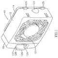
- FIG. 1shows a perspective view of the present invention.
- FIG. 2shows an exploded view of parts of the present invention.
- FIG. 3shows a schematic view of a fan device which is latched on a computer casing of the present invention.
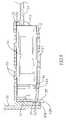
- FIG. 4shows a cross sectional view of a fan device which is latched on a computer casing of the present invention.
- FIG. 5shows a cross sectional view of a motion of removing a fan device out of a computer casing of the present invention.
- the present inventionis to provide a cooling fan locking device for a computer, including at least more than one fan device 10 composed of a primary housing 12 , an exterior surface of which is provided with an area of ventilation holes 121 , a back surface of which is provided with a sink 122 for latching with a fan 14 , a side of which is provided with at least more than one insertion slot 124 , and an edge at the other side of which is provided with at least more than one projection part 125 ; a side housing 16 , an interior of which is protruded with a plurality of insertion pieces 161 which can be inserted into the insertion slots 124 ; and a flexible press plate 126 , which is located at a side of the side housing 16 , and a surface of which is provided with a transversal flange part 127 and a locking slot 128 .
- a side wall 31 of a computer casing 30is provided with an area of a plurality of air permeable holes 32 (as shown in FIG. 4 ), and a left and right walls of the area of air permeable holes 32 are provided with right positioning slots 33 and a left positioning slot 34 , respectively.
- the projection parts 125 of primary housing 12can be latched into the right positioning slots 33 , and the flange part 127 on the press plate 126 can be latched into the left positioning slot 34 , such that the fan devices 10 can be locked and positioned at exteriors of the areas of air permeable holes 32 (as shown in FIG. 4 ).
- a concaved part 129is located below the press plate 126 , and the press plate 126 can be elastically displaced in the concaved part 129 when subjected to pressure.
- a rear side of the primary housing 12is provided with an abut part 123 which can be abutted on the side wall 31 of computer casing 30 (as shown in FIG. 3 ).
- the right positioning slots 33are located on a vertical wall at a side edge of the side wall 31
- the left positioning slots 34are located on a vertical wall 311 at a side edge of the air permeable hole 32 .
- a fan device 10is assembled from a side housing 16 , a primary housing 12 , and a fan 14 , wherein insertion pieces 161 are plural, and the neighboring insertion pieces 161 are all separated by a distance, enabling an overall thickness (or height) of the plural insertion pieces 161 to be a little larger than a width of an insertion slot 124 .
- a flexible (elastic) compression (tightening) stateis formed, such that the plural insertion pieces 161 are in a locking and positioning state within the insertion slot 124 , thereby locking the side housing 16 on the primary housing 12 .
- the fan 14 bodyis in a shape of square block, and can be fitted into a sink 122 .
- two projection parts 125are transfixed into right positioning slots 33 , such that the fan device 10 is positioned into the right positioning slots 33 and then rotated, to enable flange part 127 to be locked into left positioning slot 34 .
- a predetermined thickness 302is formed between the long-strip left positioning slot 34 and an outer edge 301 of a computer casing 30 , the flange part 127 can be latched into the left positioning slot 34 , and a locking slot 128 is exactly latched on the thickness 302 , such that the fan device 10 can be latched and fixed on the casing 30 .
- aircan be blown into the casing 30 through air permeable holes 32 to cool down parts in the casing 30 , wherein a side surface of an abut part 123 is abutted on a side wall 31 of the casing 30 , such that once the primary housing 12 is subjected to external pressure, the abut part 123 can be abutted on the side wall 31 to enhance an intensity for sustaining with the force.
- the fan device 10when the fan device 10 is to be taken out, as long as an operator uses fingers to press on a press plate 126 , enabling the press plate 126 to be elastically deformed to be flexibly displaced toward a concaved part 129 , and to pull it out, the press plate 126 will be released from the left positioning slot 34 , and the projection parts 125 will be also removed from the right positioning slots 33 . Therefore, the entire fan device 10 can be very quickly disassembled from the casing 30 (as shown in FIG. 5 ).
- the operatorusers fingers to exert force, to pull out the side housing 16 , then the plural insertion pieces 161 will be released from the insertion slot 124 , such that the plural insertion pieces 161 can be elastically restored to their original state (i.e., restoring to their original width) from the compressed state.
- the fan device 14is taken out of the sink 122 , thereby achieving objects of replacing or repairing parts.
- the cooling fan locking device of present inventionallows the fan device to be assembled on and disassembled from the computer casing 30 more quickly and conveniently, without locking and unlocking by screws.
Landscapes
- Engineering & Computer Science (AREA)
- Microelectronics & Electronic Packaging (AREA)
- Physics & Mathematics (AREA)
- Theoretical Computer Science (AREA)
- Thermal Sciences (AREA)
- Human Computer Interaction (AREA)
- General Engineering & Computer Science (AREA)
- General Physics & Mathematics (AREA)
- Cooling Or The Like Of Electrical Apparatus (AREA)
Abstract
Description
Claims (4)
Priority Applications (1)
| Application Number | Priority Date | Filing Date | Title |
|---|---|---|---|
| US11/501,014US7411788B2 (en) | 2006-08-09 | 2006-08-09 | Cooling fan device for a computer |
Applications Claiming Priority (1)
| Application Number | Priority Date | Filing Date | Title |
|---|---|---|---|
| US11/501,014US7411788B2 (en) | 2006-08-09 | 2006-08-09 | Cooling fan device for a computer |
Publications (2)
| Publication Number | Publication Date |
|---|---|
| US20080037216A1 US20080037216A1 (en) | 2008-02-14 |
| US7411788B2true US7411788B2 (en) | 2008-08-12 |
Family
ID=39050519
Family Applications (1)
| Application Number | Title | Priority Date | Filing Date |
|---|---|---|---|
| US11/501,014Active2026-09-27US7411788B2 (en) | 2006-08-09 | 2006-08-09 | Cooling fan device for a computer |
Country Status (1)
| Country | Link |
|---|---|
| US (1) | US7411788B2 (en) |
Cited By (20)
| Publication number | Priority date | Publication date | Assignee | Title |
|---|---|---|---|---|
| US20070146991A1 (en)* | 2005-12-28 | 2007-06-28 | Hon Hai Precision Industry Co., Ltd. | Mounting apparatus for fan |
| US20080090511A1 (en)* | 2006-10-17 | 2008-04-17 | Hon Hai Precision Industry Co., Ltd. | Mounting apparatus for fan |
| US20080170363A1 (en)* | 2007-01-12 | 2008-07-17 | Hon Hai Precision Industry Co., Ltd. | Computer case |
| US20100097753A1 (en)* | 2008-10-20 | 2010-04-22 | Hong Fu Jin Precision Industry (Shenzhen) Co.,Ltd. | Mounting apparatus for fan |
| US20100264293A1 (en)* | 2009-04-20 | 2010-10-21 | Cooler Master Co., Ltd. | Fan-fixing device |
| US20100290185A1 (en)* | 2009-05-14 | 2010-11-18 | Hon Hai Precision Industry Co., Ltd. | Electronic device with a fan |
| US20110073731A1 (en)* | 2009-09-29 | 2011-03-31 | Hong Fu Jin Precision Industry (Shenzhen) Co., Ltd. | Mounting apparatus for fan |
| US20110096497A1 (en)* | 2009-10-22 | 2011-04-28 | Hon Hai Precision Industry Co., Ltd. | External heat dissipation device |
| US20110149507A1 (en)* | 2009-12-23 | 2011-06-23 | Hong Fu Jin Precision Industry (Shenzhen) Co., Ltd | Computer system |
| US20110155345A1 (en)* | 2009-12-25 | 2011-06-30 | Hong Fu Jin Precision Industry (Shenzhen) Co., Ltd | Mounting apparatus for heat dissipating member |
| US20110231977A1 (en)* | 2009-12-11 | 2011-09-29 | Rupnick Charles J | Helmet cooling device |
| US20130033819A1 (en)* | 2011-08-04 | 2013-02-07 | Chien-Lin Chiu | Detachable usb fan module mounting structure |
| US20130063887A1 (en)* | 2011-09-08 | 2013-03-14 | Inventec Corporation | Server rack |
| US20130168066A1 (en)* | 2011-12-29 | 2013-07-04 | Liang-Chin Wang | Enclosure with airflow guiding duct |
| US20140205430A1 (en)* | 2013-01-24 | 2014-07-24 | Hon Hai Precision Industry Co., Ltd. | Heat-dissipation system for preventing inrush current |
| US9374914B2 (en) | 2010-04-19 | 2016-06-21 | Rittal Gmbh & Co. Kg | Air guidance unit |
| US20170016647A1 (en)* | 2014-03-24 | 2017-01-19 | Denso Corporation | Air-conditioning apparatus |
| US10779449B1 (en)* | 2019-04-11 | 2020-09-15 | Arista Networks, Inc. | Fan with EMI absorbent blades |
| US20220377936A1 (en)* | 2021-05-21 | 2022-11-24 | Runbeck Election Services Inc. | Cooling system for a printer |
| TWI845311B (en)* | 2023-05-19 | 2024-06-11 | 英業達股份有限公司 | Chassis assembly |
Families Citing this family (4)
| Publication number | Priority date | Publication date | Assignee | Title |
|---|---|---|---|---|
| KR100989139B1 (en) | 2009-01-22 | 2010-10-20 | (주)펀아이티 | Computer case for improved airflow inside the housing |
| TWI484324B (en)* | 2010-08-26 | 2015-05-11 | Hon Hai Prec Ind Co Ltd | Fixing apparatus for fan |
| DE102015114739B4 (en)* | 2015-09-03 | 2021-01-07 | Miele & Cie. Kg | Extractor hood |
| US11445633B2 (en)* | 2021-01-14 | 2022-09-13 | Super Micro Computer, Inc. | Telecommunication cabinet with hidden anti-theft heat dissipation module |
Citations (13)
| Publication number | Priority date | Publication date | Assignee | Title |
|---|---|---|---|---|
| US5822186A (en)* | 1996-02-23 | 1998-10-13 | Apple Computer, Inc. | Auxiliary electrical component utilized on the exterior of an electrical device that can be removed when the electrical device is powered |
| US6031719A (en)* | 1997-06-25 | 2000-02-29 | Dell Usa L.P. | Fan flange retention in a fan carrier |
| US6186889B1 (en)* | 1999-01-08 | 2001-02-13 | Lucent Technologies Inc. | Fan assembly module |
| US6213819B1 (en)* | 2000-04-13 | 2001-04-10 | Enlight Corporation | Detachable fan rack for computer |
| US6236564B1 (en)* | 2000-04-13 | 2001-05-22 | Enlight Corporation | Detachable fan rack mounting structure |
| US6313989B1 (en)* | 2000-08-03 | 2001-11-06 | Inventec Corporation | Fixing device for fan of computer |
| US6343011B1 (en)* | 2000-08-03 | 2002-01-29 | Lite-On Enclosure Inc. | Screwless wind conduit positioning device |
| US6504716B2 (en)* | 2001-03-27 | 2003-01-07 | Delta Electronics Inc. | Movable mechanism for using with electrical apparatus to be dissipated |
| US6817939B2 (en)* | 2002-08-13 | 2004-11-16 | Hon Hai Precision Ind. Co., Ltd | Fan holder |
| US6826048B1 (en)* | 2003-09-18 | 2004-11-30 | Hewlett-Packard Development Company, L.P. | Method and apparatus for securing a fan within a device |
| US6896611B2 (en)* | 2002-04-29 | 2005-05-24 | Hewlett-Packard Development Company, L.P. | Modular fan system |
| US6999313B2 (en)* | 2003-04-22 | 2006-02-14 | Epserv Tech Corporation | Signal connection assembly of cooling module |
| US7292436B2 (en)* | 2005-12-29 | 2007-11-06 | Inventec Corporation | Heat dissipating structure applicable to a computer host |
- 2006
- 2006-08-09USUS11/501,014patent/US7411788B2/enactiveActive
Patent Citations (13)
| Publication number | Priority date | Publication date | Assignee | Title |
|---|---|---|---|---|
| US5822186A (en)* | 1996-02-23 | 1998-10-13 | Apple Computer, Inc. | Auxiliary electrical component utilized on the exterior of an electrical device that can be removed when the electrical device is powered |
| US6031719A (en)* | 1997-06-25 | 2000-02-29 | Dell Usa L.P. | Fan flange retention in a fan carrier |
| US6186889B1 (en)* | 1999-01-08 | 2001-02-13 | Lucent Technologies Inc. | Fan assembly module |
| US6213819B1 (en)* | 2000-04-13 | 2001-04-10 | Enlight Corporation | Detachable fan rack for computer |
| US6236564B1 (en)* | 2000-04-13 | 2001-05-22 | Enlight Corporation | Detachable fan rack mounting structure |
| US6343011B1 (en)* | 2000-08-03 | 2002-01-29 | Lite-On Enclosure Inc. | Screwless wind conduit positioning device |
| US6313989B1 (en)* | 2000-08-03 | 2001-11-06 | Inventec Corporation | Fixing device for fan of computer |
| US6504716B2 (en)* | 2001-03-27 | 2003-01-07 | Delta Electronics Inc. | Movable mechanism for using with electrical apparatus to be dissipated |
| US6896611B2 (en)* | 2002-04-29 | 2005-05-24 | Hewlett-Packard Development Company, L.P. | Modular fan system |
| US6817939B2 (en)* | 2002-08-13 | 2004-11-16 | Hon Hai Precision Ind. Co., Ltd | Fan holder |
| US6999313B2 (en)* | 2003-04-22 | 2006-02-14 | Epserv Tech Corporation | Signal connection assembly of cooling module |
| US6826048B1 (en)* | 2003-09-18 | 2004-11-30 | Hewlett-Packard Development Company, L.P. | Method and apparatus for securing a fan within a device |
| US7292436B2 (en)* | 2005-12-29 | 2007-11-06 | Inventec Corporation | Heat dissipating structure applicable to a computer host |
Cited By (31)
| Publication number | Priority date | Publication date | Assignee | Title |
|---|---|---|---|---|
| US20070146991A1 (en)* | 2005-12-28 | 2007-06-28 | Hon Hai Precision Industry Co., Ltd. | Mounting apparatus for fan |
| US7599179B2 (en)* | 2005-12-28 | 2009-10-06 | Hong Fu Jin Precision Industry (Shenzhen) Co., Ltd. | Mounting apparatus for fan |
| US20080090511A1 (en)* | 2006-10-17 | 2008-04-17 | Hon Hai Precision Industry Co., Ltd. | Mounting apparatus for fan |
| US7758308B2 (en)* | 2006-10-17 | 2010-07-20 | Hon Hai Precision Industry Co., Ltd. | Mounting apparatus for fan |
| US20080170363A1 (en)* | 2007-01-12 | 2008-07-17 | Hon Hai Precision Industry Co., Ltd. | Computer case |
| US7542275B2 (en)* | 2007-01-12 | 2009-06-02 | Hon Hai Precision Industry Co., Ltd. | Computer case |
| US20100097753A1 (en)* | 2008-10-20 | 2010-04-22 | Hong Fu Jin Precision Industry (Shenzhen) Co.,Ltd. | Mounting apparatus for fan |
| US7817416B2 (en)* | 2008-10-20 | 2010-10-19 | Hong Fu Jin Precision Industry (Shenzhen) Co., Ltd. | Mounting apparatus for fan |
| US20100264293A1 (en)* | 2009-04-20 | 2010-10-21 | Cooler Master Co., Ltd. | Fan-fixing device |
| US8267369B2 (en)* | 2009-04-20 | 2012-09-18 | Cooler Master Co., Ltd. | Fan-fixing device |
| US20100290185A1 (en)* | 2009-05-14 | 2010-11-18 | Hon Hai Precision Industry Co., Ltd. | Electronic device with a fan |
| US7990707B2 (en)* | 2009-05-14 | 2011-08-02 | Hon Hai Precision Industry Co., Ltd. | Electronic device with a fan |
| US20110073731A1 (en)* | 2009-09-29 | 2011-03-31 | Hong Fu Jin Precision Industry (Shenzhen) Co., Ltd. | Mounting apparatus for fan |
| US20110096497A1 (en)* | 2009-10-22 | 2011-04-28 | Hon Hai Precision Industry Co., Ltd. | External heat dissipation device |
| US7948754B2 (en)* | 2009-10-22 | 2011-05-24 | Hon Hai Precision Industry Co., Ltd. | External heat dissipation device |
| US20110231977A1 (en)* | 2009-12-11 | 2011-09-29 | Rupnick Charles J | Helmet cooling device |
| US20110149507A1 (en)* | 2009-12-23 | 2011-06-23 | Hong Fu Jin Precision Industry (Shenzhen) Co., Ltd | Computer system |
| US20110155345A1 (en)* | 2009-12-25 | 2011-06-30 | Hong Fu Jin Precision Industry (Shenzhen) Co., Ltd | Mounting apparatus for heat dissipating member |
| US9374914B2 (en) | 2010-04-19 | 2016-06-21 | Rittal Gmbh & Co. Kg | Air guidance unit |
| US8503177B2 (en)* | 2011-08-04 | 2013-08-06 | Adlink Technology Inc. | Detachable USB fan module mounting structure |
| US20130033819A1 (en)* | 2011-08-04 | 2013-02-07 | Chien-Lin Chiu | Detachable usb fan module mounting structure |
| US8665590B2 (en)* | 2011-09-08 | 2014-03-04 | Inventec Corporation | Server rack |
| US20130063887A1 (en)* | 2011-09-08 | 2013-03-14 | Inventec Corporation | Server rack |
| US20130168066A1 (en)* | 2011-12-29 | 2013-07-04 | Liang-Chin Wang | Enclosure with airflow guiding duct |
| US20140205430A1 (en)* | 2013-01-24 | 2014-07-24 | Hon Hai Precision Industry Co., Ltd. | Heat-dissipation system for preventing inrush current |
| US20170016647A1 (en)* | 2014-03-24 | 2017-01-19 | Denso Corporation | Air-conditioning apparatus |
| US10295219B2 (en)* | 2014-03-24 | 2019-05-21 | Denso Corporation | Air conditioning case positioning pin and holding piece that engage an attachment part projection piece |
| US10779449B1 (en)* | 2019-04-11 | 2020-09-15 | Arista Networks, Inc. | Fan with EMI absorbent blades |
| US20220377936A1 (en)* | 2021-05-21 | 2022-11-24 | Runbeck Election Services Inc. | Cooling system for a printer |
| US12016152B2 (en)* | 2021-05-21 | 2024-06-18 | Runbeck Election Services Inc. | Cooling system for a printer |
| TWI845311B (en)* | 2023-05-19 | 2024-06-11 | 英業達股份有限公司 | Chassis assembly |
Also Published As
| Publication number | Publication date |
|---|---|
| US20080037216A1 (en) | 2008-02-14 |
Similar Documents
| Publication | Publication Date | Title |
|---|---|---|
| US7411788B2 (en) | Cooling fan device for a computer | |
| US7699582B2 (en) | Fan module | |
| US7599179B2 (en) | Mounting apparatus for fan | |
| US7471514B2 (en) | Auxiliary cooling device for memory chips | |
| US8939721B2 (en) | Fan assembly | |
| US7261383B2 (en) | Computer enclosure with latch device | |
| US20110255235A1 (en) | Disk Drive Case | |
| US7525802B2 (en) | Computer with heat dissipation system | |
| WO2012133497A1 (en) | Fan chassis, fan unit, and communication device | |
| US7469978B2 (en) | Block-shape container which can be assembled into and disassembled from a computer casing | |
| JP4073422B2 (en) | Screw-free fan holder fixing device | |
| US7611328B2 (en) | Mounting apparatus for fans | |
| US20130168530A1 (en) | Mounting apparatus for fan module | |
| US20130216374A1 (en) | Fixing apparatus for fan | |
| US7355115B2 (en) | Computer casing baffle plate device | |
| TW201347654A (en) | PCI card securing structure | |
| US20090129019A1 (en) | Heat dissipation device with fan holder | |
| US7817416B2 (en) | Mounting apparatus for fan | |
| US20060279912A1 (en) | Keyboard mounting apparatus for portable computer | |
| US20140076828A1 (en) | Mounting device for fan | |
| US20140185236A1 (en) | Cooling module and computer enclosure using the same | |
| CN112153843B (en) | Electronic device with door cover | |
| CN104866033A (en) | Fan fixing combination | |
| US12163534B1 (en) | Fan fixing device for electronic device | |
| US20130216412A1 (en) | Fixing apparatus for fan |
Legal Events
| Date | Code | Title | Description |
|---|---|---|---|
| AS | Assignment | Owner name:SUPER MICRO COMPUTER, INC., CALIFORNIA Free format text:ASSIGNMENT OF ASSIGNORS INTEREST;ASSIGNOR:LIANG, CHIEN-FA;REEL/FRAME:018174/0476 Effective date:20060606 | |
| AS | Assignment | Owner name:SUPER MICRO COMPUTER, INC., CALIFORNIA Free format text:ASSIGNMENT OF ASSIGNORS INTEREST;ASSIGNOR:LIANG, CHIEN-FA;REEL/FRAME:019071/0408 Effective date:20060606 | |
| STCF | Information on status: patent grant | Free format text:PATENTED CASE | |
| FPAY | Fee payment | Year of fee payment:4 | |
| FEPP | Fee payment procedure | Free format text:PAT HOLDER NO LONGER CLAIMS SMALL ENTITY STATUS, ENTITY STATUS SET TO UNDISCOUNTED (ORIGINAL EVENT CODE: STOL); ENTITY STATUS OF PATENT OWNER: LARGE ENTITY | |
| SULP | Surcharge for late payment | ||
| FPAY | Fee payment | Year of fee payment:8 | |
| AS | Assignment | Owner name:BANK OF AMERICA, N.A, AS ADMINSTRATIVE AGENT, CALI Free format text:SECURITY INTEREST;ASSIGNOR:SUPER MICRO COMPUTER, INC;REEL/FRAME:046029/0940 Effective date:20180419 | |
| MAFP | Maintenance fee payment | Free format text:PAYMENT OF MAINTENANCE FEE, 12TH YEAR, LARGE ENTITY (ORIGINAL EVENT CODE: M1553); ENTITY STATUS OF PATENT OWNER: LARGE ENTITY Year of fee payment:12 | |
| AS | Assignment | Owner name:SUPER MICRO COMPUTER, INC., CALIFORNIA Free format text:RELEASE BY SECURED PARTY;ASSIGNOR:BANK OF AMERICA, N.A., AS AGENT;REEL/FRAME:069436/0469 Effective date:20241119 |