US7411711B2 - High speed, high efficiency optical pattern generator using rotating optical elements - Google Patents
High speed, high efficiency optical pattern generator using rotating optical elementsDownload PDFInfo
- Publication number
- US7411711B2 US7411711B2US11/679,117US67911707AUS7411711B2US 7411711 B2US7411711 B2US 7411711B2US 67911707 AUS67911707 AUS 67911707AUS 7411711 B2US7411711 B2US 7411711B2
- Authority
- US
- United States
- Prior art keywords
- pattern generator
- optical
- offset
- optical element
- scan
- Prior art date
- Legal status (The legal status is an assumption and is not a legal conclusion. Google has not performed a legal analysis and makes no representation as to the accuracy of the status listed.)
- Expired - Fee Related
Links
Images


Classifications
- G—PHYSICS
- G02—OPTICS
- G02B—OPTICAL ELEMENTS, SYSTEMS OR APPARATUS
- G02B26/00—Optical devices or arrangements for the control of light using movable or deformable optical elements
- G02B26/08—Optical devices or arrangements for the control of light using movable or deformable optical elements for controlling the direction of light
- G02B26/10—Scanning systems
- G02B26/105—Scanning systems with one or more pivoting mirrors or galvano-mirrors
- G—PHYSICS
- G02—OPTICS
- G02B—OPTICAL ELEMENTS, SYSTEMS OR APPARATUS
- G02B26/00—Optical devices or arrangements for the control of light using movable or deformable optical elements
- G02B26/08—Optical devices or arrangements for the control of light using movable or deformable optical elements for controlling the direction of light
- G02B26/0875—Optical devices or arrangements for the control of light using movable or deformable optical elements for controlling the direction of light by means of one or more refracting elements
- G—PHYSICS
- G02—OPTICS
- G02B—OPTICAL ELEMENTS, SYSTEMS OR APPARATUS
- G02B26/00—Optical devices or arrangements for the control of light using movable or deformable optical elements
- G02B26/08—Optical devices or arrangements for the control of light using movable or deformable optical elements for controlling the direction of light
- G02B26/10—Scanning systems
- G—PHYSICS
- G02—OPTICS
- G02B—OPTICAL ELEMENTS, SYSTEMS OR APPARATUS
- G02B13/00—Optical objectives specially designed for the purposes specified below
- G02B13/0095—Relay lenses or rod lenses
- G—PHYSICS
- G02—OPTICS
- G02B—OPTICAL ELEMENTS, SYSTEMS OR APPARATUS
- G02B27/00—Optical systems or apparatus not provided for by any of the groups G02B1/00 - G02B26/00, G02B30/00
- G02B27/30—Collimators
- Y—GENERAL TAGGING OF NEW TECHNOLOGICAL DEVELOPMENTS; GENERAL TAGGING OF CROSS-SECTIONAL TECHNOLOGIES SPANNING OVER SEVERAL SECTIONS OF THE IPC; TECHNICAL SUBJECTS COVERED BY FORMER USPC CROSS-REFERENCE ART COLLECTIONS [XRACs] AND DIGESTS
- Y10—TECHNICAL SUBJECTS COVERED BY FORMER USPC
- Y10S—TECHNICAL SUBJECTS COVERED BY FORMER USPC CROSS-REFERENCE ART COLLECTIONS [XRACs] AND DIGESTS
- Y10S359/00—Optical: systems and elements
- Y10S359/90—Methods
Definitions
- This inventionrelates generally to optically generating a pattern of figures, such as an array of spots or an array of scan lines. More particularly, this invention relates to generating such patterns using multi-faceted rotating optical elements.
- optical generation of a pattern of spots or scan linesis used in a variety of applications.
- Digital copiers, printers, fingerprint identification, hand-held bar code scanners, industrial applications, light show entertainment, displays, telecommunications switching and medical applicationsare a few examples.
- Perhaps the most common mechanisms for generating patterns of figuresare tilting mirrors (e.g., oscillating mirrors driven by galvanometers) and reflections from rotating polygons.
- optical pattern generators based on tilting mirrorstypically have characteristics that make them unsuitable for certain applications. For example, scanning in these systems is typically achieved by tilting a mirror back and forth. But back and forth motion requires that the mirror come to a stop and then reverse direction. This takes time, which limits the scan rate. In order to increase the scan rate of these systems, the mirror often is driven with an oscillating motion at a rate that is near its resonant frequency. However, this severely restricts the patterns that can be generated. For example, it is difficult to generate irregular patterns since the mirror motion is constrained to be oscillatory. The near-resonance condition also limits the range of scan rates that can be achieved.
- a two-dimensional patterne.g., a series of parallel scan lines or a two-dimensional pattern of spots
- typically either a single mirror is tilted in two directions simultaneously or two coordinated, tilting mirrorsare used.
- the efficiency of the utilization of light, such as laser lightis also important. The efficiency may be defined as the fraction of energy deposited in a desired pattern on the treatment surface compared to the total energy produced by the light source in a given period of time.
- a patternis sparse compared to the background, it is preferable to turn off the light source and scan quickly over the background, and then turn it back on when the light beam has settled over the spot to be exposed and expose the spots in the pattern in such a manner that the light source is efficiently utilized in time.
- Thisrequires an even more responsive device that can accelerate, decelerate and settle quickly.
- galvanometer-based systemsare not well suited for high speed pattern generation, particularly if the pattern is an irregular or a sparse one.
- the sides of a three-dimensional polygonare mirrored and the polygon is rotated about a center axis.
- the optical beamis reflected to generate a point on a scan line.
- the rotation of each mirrored side through the optical beamproduces one scan line. If all of the mirrored sides are the same (e.g., make the same pyramid angle with the base of the polygon), then the same scan line is traced over and over. If the mirrored sides are different, then different scan lines can be traced as each side rotates through the optical beam. For example, by varying the pyramid angle of each side, the reflected optical beam can trace a series of scan lines.
- each sidehas a different pyramid angle that offsets the basic scan line in a direction that is perpendicular to the scan direction.
- the orientation of the angled sideis also rotated. This can cause changes in the amount of offset and/or other unwanted aberrations.
- One exampleis scan line bow.
- the ideal scan lineis generally a straight line segment but the actual scan line is often an arc segment. The sag of the arc segment is the bow.
- Scan line bow and other effects caused by rotationcan cause additional problems, depending on the application.
- the scanning actionis used to compensate for motion of the scanner relative to a target so that the optical beam ideally remains at a fixed spot on the target even though the scanner is moving relative to the target.
- scan line bowwill cause the optical beam to move in the direction perpendicular to the scan direction. If this motion is slow compared to the dwell time of the optical beam on the target, then the bow effectively introduces an unwanted motion in the perpendicular direction.
- the bowwhich is a radial deflection, when combined with the uncompensated tangential motion, effectively blurs the optical beam, increasing the spot size of the beam on the target.
- neither effectis desirable.
- one or more multi-faceted rotating optical elementsintroduce an offset that is rotation insensitive.
- the component that generates the offsetis rotationally symmetric around the rotational axis of the optical element.
- the effect of the offset componentdoes not change.
- two or more multi-faceted rotating optical elementsare used to counteract unwanted effects produced by each other.
- one rotating optical elementintroduces a deflection but also some unwanted optical power.
- a second rotating optical elementcounteracts the optical power while reinforcing the deflection. The result is a deflected beam with no additional optical power.
- the rotating optical elementsgenerate scan lines and the scan line bow introduced by one rotating optical element counteracts the bow introduced by other rotating optical elements, while reinforcing the desired scan.
- an optical pattern generatorincludes a multi-faceted rotating optical element having a plurality of facets.
- Each facetcauses an incident optical beam to generate a figure (e.g., a spot or a scan line) as the facet rotates through the optical beam.
- the facetstogether generate an array of figures.
- One or more facetsinclude an offset component that is substantially rotationally symmetric and substantially centered on the rotational axis of the rotating optical element. The offset component offsets the figure along an offset direction, which is generally aligned with a radial direction of the rotating optical element.
- different facetsoffset the figures by different amounts.
- the facetscan be arranged so that the figures are offset by uneven amounts and/or generated in a non-sequential order.
- the figurecan be more complex than a spot or a scan line and the figure can vary over time.
- the pattern generatorcan be combined with another motion or scanning mirror.
- the resulting patterncan be a changing two-dimensional image, such as in a video display.
- the facets on both scan disksinclude an offset component as described above.
- the offset componentsare implemented as a positive lens-like element on one scan disk and a negative lens-like element on the other scan disk.
- the powers of the lens-like elementsvary from facet to facet, with different facets introducing different offsets.
- the facetsmay also include scan components to generate a scan line, for example with the scan component on one facet introducing a bow that counteracts the bow introduced by the scan component on the other facet.
- an optical pattern generatordeflects an optical axis along an array of scan lines.
- the optical pattern generatorincludes two multi-faceted rotating optical elements, with one optical element located downstream of the other.
- the two rotating optical elementsare counter-rotating and have corresponding facets.
- the facetscause the optical axis to deflect along a scan line as the facets rotate through the optical axis.
- the optical elementsmay also implement bow correction and/or offset of scan lines, as described above. This type of pattern generator can be used in many different applications, including both systems that generate optical figures and imaging systems.
- different devicesinclude various combinations of the offset functions, scan line functions and counteracting principles described above.
- rotating optical elementsare combined with conventional scanners.
- Other aspects of the inventioninclude methods corresponding to the devices described above, and applications for all of the foregoing, including for example using the scan lines to compensate for motion.
- FIG. 1Ais a side cross section of an optical pattern generator according to one aspect of the invention.
- FIG. 1Bis a perspective view of the optical train of the pattern generator of FIG. 1A .
- FIG. 1Cis a diagram illustrating offset of scan lines.
- FIG. 2is a ray trace through two offset components.
- FIG. 3Ais a diagram illustrating an offset pattern.
- FIG. 3Bis a top view of a scan disk used to generate the offset pattern of FIG. 3A .
- FIG. 4Ais a top view of the rotating optical elements of the pattern generator of FIG. 1 .
- FIG. 4Bis a diagram illustrating bow correction in a scan line produced by the rotating optical elements of FIG. 4A .
- FIG. 5Ais a perspective view of another pattern generator according to the invention.
- FIG. 5Bis a ray trace through the pattern generator of FIG. 5A .
- FIG. 6is a ray trace through another pattern generator according to the invention.
- FIGS. 7A-7Care diagrams illustrating various patterns generated by systems using a pattern generator according to the invention.
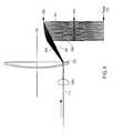
- FIGS. 1A-1Cillustrate one example of an optical pattern generator 100 according to the invention.
- the optical train of the pattern generator 100includes one or more optical sources 110 A-E and one or more multi-faceted rotating optical elements 120 A-B. It may also include additional optics 130 A-B for shaping the optical beam(s) as they pass through the optical train to the target surface 150 .
- the optical source 110produces an optical beam(s) that is incident upon the rotating optical elements 120 .
- Each rotating optical element 120has a number of facets, and facets on one rotating optical element 120 have corresponding facets on the other optical elements 120 .
- the rotation of the optical elements 120is synchronized so that corresponding facets rotate through the incident optical beam in synchronization.
- the optical beamsgenerate FIGS. 140A-E on the target surface 150 as the facets rotate through the optical beams.
- the FIGS. 140A-Eare scan lines, although they can be spots or other shapes in alternate embodiments.
- the scan direction 142is in and out of the paper.
- the facetsalso offset the scan lines 140 in a direction 144 perpendicular to the scan direction 142 .
- one set of corresponding facets on the scan disksmay produce the set of scan lines 140 A-E, with each of the five scan lines traced by the corresponding optical beam.
- the next set of corresponding facetsmay produce the scan lines 141 A-E, which is offset by an amount ⁇ relative to the scan lines 140 .
- the portions of the facets that cause the optical beams to trace the scan linesshall be referred to as scan components and the portions that cause the offset of the scan lines shall be referred to as offset components.
- scan componentsmay be implemented as physically distinct components, for example the scan component can be attached to one side of the optical element 120 and the offset component to the reverse side. Alternately, they may be integrated into a single component.
- a general aspheremay be used, with the asphere implementing both the scanning and the offset functions.
- the scanning and offset functionscan be generated by a spherical surface that has its axis of symmetry slightly displaced from the axis of rotation of the disk to which it has been mounted.
- this example pattern generatorhas both scanning and offset, but alternate embodiments may utilize only scanning or only offset.
- collimation optics 130 Acollimate the optical beams from the five fibers.
- Two scan disks 120 A-Bare located in close proximity to plane 160 , one on each side of the plane. Plane 160 is where the chief rays of the five optical beams cross.
- the rotational axes 125 of the scan disksare located on opposite sides of the optical beams.
- the scan disks 120are counter-rotating (i.e., if one rotates clockwise, the other rotates counter-clockwise) so that corresponding facets generally travel together as they rotate through the optical beam.
- Focusing optics 130 Brefocus the deflected collimated beams to spots on the target surface 150 .
- the spotstrace out scan lines 140 due to the scanning action of the facets, and the scan lines are offset due to the offset action of the facets.
- Motorsrotate the scan disks 120 .
- FIG. 2illustrates the offset component of the facets.
- the offset component that generates the offsetmay be a prism.
- the prismalso rotates and this can introduce unwanted effects, such as unintentional scanning of the optical beam.
- the offset components in this exampleare rotationally symmetric about the rotational axis of the respective optical element 120 .
- the optical element 120rotates, there is no change in the optical effect of the offset component.
- One example of such an offset componentis a portion of a sphere, where the axis of the sphere is aligned with the rotational axis of the scan disk. Spheres with a shorter radius result in a greater offset of the spherical surface at the centerline of the optical beam.
- FIG. 2illustrates a specific example of a rotationally symmetric offset component.
- the offset components on the two scan disks 120 A-Bare lenses 320 centered about the respective rotational axes 125 A-B of the scan disks.
- the offset componentshave optical powers that are equal in magnitude but opposite in sign, and the optical beam 210 is located midway between the two rotational axes 125 .
- the offset component 320 Ais a lens with negative (divergent) optical power
- offset component 320 Bis a lens with positive power.
- the lens 320 ADue to the diverging nature of the lens 320 A, after passage through this lens, the light appears to radiate from a point source located on the rotational axis of the lens (which in this case is also the rotational axis 125 A of the scan disk). Since the optical beam 210 has a small diameter relative to the lens 320 A, this effect is primarily a deflection of the optical beam 210 away from the rotational axis 125 A. In addition, the individual light rays in the optical beam begin to diverge away from each other and, if allowed to propagate a long distance, the optical beam would begin to broaden. However, the optical beam very soon reaches the second offset component 320 B, which has an optical power that is very nearly equal and opposite to that of the first.
- the optical beamemerges essentially collimated.
- the rotational axis 125 B of the positive lens 320 Bis on the opposite side of the optical beam as the axis 125 A for the negative lens 320 A
- the deflection imparted by the second lens 320 Badds to the deflection imparted by the first lens 320 A.
- the incoming collimated beamleaves the two scan disks 120 still collimated but deflected by a certain amount.
- this amount of deflection and the shape of the outgoing beamdo not change as the scan disks 120 rotate since the offset components are rotationally symmetric about the axes of rotation.
- FIG. 2shows the lenses 320 A and 320 B as entire lenses. This was done for illustrative purposes. In the actual implementation, each lens 320 does not cover the entire scan disk 120 . Rather, each lens covers a facet on the scan disk.
- Different facetscan use lenses of different powers. For example, one pair of corresponding facets may contain a strong positive lens and a strong negative lens, thus causing a strong deflection. The next pair of corresponding facets may contain a weaker positive lens and a weaker negative lens, thus causing a weaker deflection. As the different pairs of facets rotate through the incident optical beam, the beam is deflected by different amounts due to the different optical powers in the lenses. However, the beams all emerge collimated. Thus, focusing optics can be used to focus the emerging beams onto a flat target field.
- FIG. 3Ashows the offsets 341 - 349 to be generated. Note that FIG. 3A is a depiction of the offset pattern. If the figures generated by the system are spots, then an array of offset spots will be generated. If the figures are scan lines, then an array of offset scan lines will be generated. If multiple optical beams are used (as in FIG. 1 ), then the basic pattern will be replicated. If a more complex object source which changes in time is used, the image of that source will be replicated and will change in time.
- FIG. 3Bshows one of the pair of rotating optical elements used to generate these offsets. The rotating optical element has facets 361 - 369 and so on.
- each offset 141 - 149is generated by a corresponding pair of facets 361 - 369 , but the facets can be designed independently of each other. Therefore, the offsets can be unevenly spaced, as shown in FIG. 3A .
- the figurescan be generated in a non-sequential order. That is, it is not required that facet 361 generates offset 341 , facet 362 generates offset 342 , facet 363 generates offset 343 , etc. Instead, facets 361 - 369 might generate offsets 341 , 344 , 347 , 342 , 348 , 343 , 345 , 349 , and 346 , respectively.
- facets 361 , 364 and 367might all generate offset 344 .
- This characteristicallows the generation of irregular patterns. Irregular two-dimensional patterns can be generated by using two crossed systems, one causing deflection in the x direction and the other causing deflection in the y direction. Alternately, this approach can be combined with an ordinary galvanometer mirror or polygon mirror scanner to create two-dimensional patterns.
- Diskscan be rotated at very high speeds. For example, if a disk contains 30 facets and rotates at a speed of 10,000 rpm, then the system will generate 5,000 figures per second, if there is a single beam source. If the source has N beams, 5,000N figures per second will be generated. Furthermore, the speed can be varied over a wide range since there is no requirement to stay near a resonant frequency.
- the drive shafts or the disks themselvesare encoded and this feedback is used to both control the speed of the disks and to synchronize the disks with each other.
- the offset componentis exactly rotationally symmetric and exactly centered on the rotational axis of the optical element, then the offset, which will be in the radial direction, will not vary as the offset component rotates through the optical beam. If there are no other components on the facet, then the system will generate an array of spots offset in the radial direction.
- the offset componentmay be slightly decentered from the rotational axis of the optical element, for example to introduce a scanning motion. Any scanning motion can be broken into a radial component and a tangential component.
- the symmetry in FIG. 2allows the two disks to be designed so that the radial components from corresponding facets cancel and the tangential components reinforce. For example, if the two lenses 320 A and 320 B have the same (but opposite) power, they can be decentered by the same amount relative to their rotational axes 125 , toward one another or away from one another. The result is a scan line that is purely in the tangential direction since the radial scan effects from the two lenses 320 cancel.
- FIGS. 4A-4Bfurther illustrate how facets can be designed so that their radial scan effects cancel.
- Scan componentsgenerally introduce a bow in the scan line as they rotate through the incident optical beam.
- the scan component on each scan diskmay introduce a bow
- the two scan componentsare designed so that the different bows counteract each other and the overall bow is reduced or eliminated.
- a scan componentis an off-center lens.
- a scan linecan be created by moving a lens through an optical beam.
- the optical beam 210is normally incident to the scan disk 120 A and that the scan component of the current facet has the same optical effect as a lens with positive optical power (negative power lenses can also be used), as represented by the circle 220 .
- the circle representationis not meant to imply that the scan component must be circular in shape. For example, it may have the same shape of the facet.
- the optical beamis initially directed to the center of the circle 220 . As the facet rotates through the optical beam 210 , the center of the circle 220 also rotates about the rotational axis 125 A. The resulting scan line follows the motion of the lens, tracing out an arc 240 A as shown in FIG. 4B . The sag of the arc is the bow of this scan line.
- This bowcan be reduced, or even eliminated, as follows. If the scan component on scan disk 120 B is also a lens with positive optical power, it will trace the arc 240 B. But this arc is bowed in the opposite direction as arc 240 A. The two bows counteract each other, resulting in a net scan line 245 that scans faster and is longer and with less bow. In some cases, the bow can be entirely eliminated. For example, this will be the case if the scan disks 120 A-B are in close proximity to each other (so that propagation between the scan disks has negligible effect), the distance from the optical beam 210 to each rotational axis 125 is the same, and both scan components are lenses with the same optical power located in the same relative position on their respective facets.
- FIG. 1shows a case with five optical beams
- FIG. 1shows a case with five optical beams
- a single facet or exactly the same facet replicated over the entire scan diskEach scan disk 120 contains multiple facets and each set of corresponding facets produces a figure (e.g., a spot or a scan line). If the facets on a scan disk are all the same, then the same figure will be repeated over and over with the same offset.
- the facetscan also be different in order to produce different figures or figures with different offsets.
- different scan componentscan be used on different facets in order to generate different lengths of scan lines.
- different offset componentse.g., lenses with different optical power
- scan components and offset componentscan be combined in various ways to achieve different scan patterns.
- the bow correction and offset components described aboveneed not be used with every facet.
- a particular facet(s)may be designed for zero offset, in which case offset components are not necessary.
- a majority of facets but not all facetsmay utilize offset components.
- the undesirable effects introduced by conventional techniquesmay be tolerable so that bow correction and/or offset techniques are not necessary.
- every facetmay utilize the bow correction and/or offset components described above.
- the physical implementations of the scan component and offset componentcan also vary. For facets that include a separate scan component and offset component, different designs can place these components in different orders within the optical train.
- the scan component and offset componentcan also be integrated into a single optical component.
- the scan componentis implemented as a lens centered at approximately the same radial location as the optical beam and the offset component is implemented as a lens centered on the rotational axis of the scan disk.
- the net effect of these two lensesis the same as that of a single lens that has an optical power approximately equal to the sum of the optical powers of the scan component and the offset component and central axis that is located elsewhere.
- the two componentscan be implemented as a single lens.
- the incident beam and the beam exiting the counter rotating disksare collimated, that is not a requirement for practical use, since the objective lens that focuses the exiting beam can be modified to accommodate power in the scanned beams. In some instances even different amounts of power from the different facet sets can be accommodated.
- transmissive facetsbut reflective or hybrid designs can also be used.
- the scan components and offset componentscan also be based on refraction, reflection, diffraction or a combination of these.
- Mirrors, conventional lenses, aspheres, Fresnel lenses, kinoforms, diffractive and holographic opticsare examples of possible physical implementations.
- the term “lens-like optical element”will be used to refer to refractive lenses, curved mirrors, holographic lenses and other optical elements that are counterparts to refractive lenses.
- FIGS. 5A-5Billustrate a reflective design.
- the optical sourceis a fiber laser at a wavelength of 1535 nm.
- Collimation optics 130 Acollimate the incoming optical beam onto two reflective rotating scan disks 120 A- 120 B, which are tilted at 19 degrees from normal.
- Each scan disk 120is approximately 30-50 mm in diameter with 15-30 facets each.
- the facetstypically extend roughly 5 mm in the tangential direction and slightly less than that in the radial direction.
- the incident optical beamis approximately 1.0-1.5 mm in diameter.
- the focusing optics 130 Bincludes a triplet for focusing the deflected optical beam onto the target.
- FIGS. 5show the optical beam at five different offsets 541 - 545 . There are 15-30 offsets (one for each facet), that are evenly spaced approximately 0.75 mm apart, for a full target width of about 15 mm.
- the optical beamremains focused on a single point on the skin for the scan duration of a single facet.
- U.S. patent application Ser. No. 10/745,761“Method And Apparatus for Monitoring and Controlling Laser-Induced Tissue Treatment,” filed on Dec. 23, 2003 and incorporated herein by reference.
- Another treatment spotis generated at a different location.
- the disks 120are designed to rotate up to 6000 rpm, resulting in a treatment rate of up to 3000 spots per second.
- FIG. 6is an example of an optical pattern generator using one rotating optical element.
- the incoming optical beamarrives via an optical fiber 110 and is collimated by collimation optics 130 A.
- the collimated beamis incident upon the rotating optical element 120 .
- the optical element 120is depicted as a lens in FIG. 6 in order to illustrate the offset function.
- the optical element 120contains approximately 20 facets, each of which has an offset component that is implemented as a lens centered on the rotational axis 125 .
- Each lenshas a different power and deflects the incoming optical beam by a different amount.
- FIG. 6shows all twenty of the deflected beams 641 - 649 .
- the weakest lensgenerates the least deflected beam 641 and the strongest lens generates the most deflected beam 649 .
- the different power lensesalso introduce different amounts of focusing to each of the beams 641 - 649 . In FIG. 2 , this was counteracted by a second lens of equal but opposite power.
- an echelon type mirror array 632is used to individually redirect each beam 641 - 649 to the target and a lens array 634 individually focuses each beam 641 - 649 on the target 150 .
- Examples of dermatology laser light sourcesinclude diode lasers, diode-pumped solid state lasers, Er:YAG lasers, Nd:YAG lasers, argon-ion lasers, He-Ne lasers, carbon dioxide lasers, excimer lasers, erbium fiber lasers, and ruby lasers. These devices generate laser beams having the wavelength in the visible range of the spectrum (0.4-0.7 ⁇ m) as well as in infrared (0.7-11 ⁇ m) and UV (0.18-0.40 ⁇ m) ranges. It should be noted that terms such as “optical” and “light” are meant to include all of these and other wavelength regions and not just the visible range of the spectrum.
- the figures generatedcan also take different forms.
- a single continuous scan lineis traced repeatedly.
- a series of parallel scan linesis produced, laterally offset from each other.
- the scan linescan also be a series of points rather than a continuous line, for example if a source laser is pulsed on and off during scanning.
- scanningcan also be used to compensate for motion so that the scan spot remains in a fixed position on a target even though the scanning device is moved relative to the target.
- Other variationswill be apparent.
- the number of rotating optical elements 120can also vary.
- the above examples(other than FIG. 6 ) all use a pair of scan disks but this is not a requirement.
- two or more pairs of rotating optical elementscan be used.
- the two-disk designscan be converted to three-disk designs by “splitting” one of the scan disks into two scan disks.
- the positive lens 320 Bcan be split into two positive lenses with half the power, one placed upstream of the negative lens 320 A and the other placed downstream of the negative lens 320 A.
- the basic pattern generatorcan also be used in many different applications.
- the rotating optical elementsintroduce a deflection to the optical axis of the overall system. If the facets include offset components, then the deflection includes an offset generally along a radial direction. If the facets include scan components, then the deflection includes a scan line, typically along a tangential direction. For example, a system that uses a 20 mm focal length objective lens with a 1 mm scan line will introduce a deflection of 0.05 radians. Different applications can use either or both of these, possibly in combination with other deflection mechanisms.
- FIGS. 7A-7Cillustrate different patterns that can be generated by systems using a pattern generator.
- the pattern generatoris optically coupled to another scanning device, such as a conventional polygon scanner.
- the conventional scanning devicealone would generate a scan line, such as 711 .
- the pattern generatorgenerates a pure offset (no scanning), as depicted by the offsets between the scan lines 711 - 714 .
- the pattern generatoroperates at a much faster rate than the other scanning device.
- the set of offsetsis cycled through multiple times in the time required for the conventional scanner to generate one scan line.
- the resulting patternis a set of “dashes” 721 as shown in FIG. 7A .
- Each dash 721corresponds to one facet (or set of corresponding facets) rotating through an incident optical beam.
- the facets on the pattern generatoralso contain a scan component that counteracts the scan produced by the conventional scanning device.
- the dashes 721 in FIG. 7Aare compressed into spots 722 in FIG. 7B .
- the scan component on the facetcounteracts the conventional scanner, thus holding the optical beam at a fixed location.
- the optical beamjumps to the next location, which in this example also includes a lateral offset.
- the pattern generatordoes not introduce a lateral offset. Rather, the scan components in the pattern generator counteract the conventional scanner generating a row 711 of spots 722 . When the row is completed, an offset is introduced (e.g., by another conventional scanner) to generate a next row 712 of spots. In this way, a display can be built.
- the optical pattern generatorcan also be used in imaging or sensing systems.
- the object sourceis located at the focal plane of the scanner and the sensor (such as a CCD) is located at the opposite end of the scanner.
- the scan componentscan be used to compensate for the motion of an object that is to be imaged.
- the scanningcan be used for deblurring in the image capture. Application can be found in streak cameras.
Landscapes
- Physics & Mathematics (AREA)
- General Physics & Mathematics (AREA)
- Optics & Photonics (AREA)
- Facsimile Scanning Arrangements (AREA)
- Mechanical Optical Scanning Systems (AREA)
Abstract
Description
Claims (24)
Priority Applications (3)
| Application Number | Priority Date | Filing Date | Title |
|---|---|---|---|
| US11/679,117US7411711B2 (en) | 2003-12-31 | 2007-02-26 | High speed, high efficiency optical pattern generator using rotating optical elements |
| US11/982,147US7636186B2 (en) | 2003-12-31 | 2007-10-31 | High speed, high efficiency optical pattern generator using rotating optical elements |
| US11/952,925US7557975B2 (en) | 2003-12-31 | 2007-12-07 | High speed, high efficiency optical pattern generator using rotating optical elements |
Applications Claiming Priority (2)
| Application Number | Priority Date | Filing Date | Title |
|---|---|---|---|
| US10/750,790US7184184B2 (en) | 2003-12-31 | 2003-12-31 | High speed, high efficiency optical pattern generator using rotating optical elements |
| US11/679,117US7411711B2 (en) | 2003-12-31 | 2007-02-26 | High speed, high efficiency optical pattern generator using rotating optical elements |
Related Parent Applications (1)
| Application Number | Title | Priority Date | Filing Date |
|---|---|---|---|
| US10/750,790ContinuationUS7184184B2 (en) | 2003-12-23 | 2003-12-31 | High speed, high efficiency optical pattern generator using rotating optical elements |
Related Child Applications (2)
| Application Number | Title | Priority Date | Filing Date |
|---|---|---|---|
| US11/982,147DivisionUS7636186B2 (en) | 2003-12-31 | 2007-10-31 | High speed, high efficiency optical pattern generator using rotating optical elements |
| US11/952,925DivisionUS7557975B2 (en) | 2003-12-31 | 2007-12-07 | High speed, high efficiency optical pattern generator using rotating optical elements |
Publications (2)
| Publication Number | Publication Date |
|---|---|
| US20070145146A1 US20070145146A1 (en) | 2007-06-28 |
| US7411711B2true US7411711B2 (en) | 2008-08-12 |
Family
ID=34701246
Family Applications (8)
| Application Number | Title | Priority Date | Filing Date |
|---|---|---|---|
| US10/750,790Expired - Fee RelatedUS7184184B2 (en) | 2003-12-23 | 2003-12-31 | High speed, high efficiency optical pattern generator using rotating optical elements |
| US11/339,097Expired - LifetimeUS7265884B2 (en) | 2003-12-31 | 2006-01-24 | High speed, high efficiency optical pattern generator using rotating optical elements |
| US11/339,005Expired - Fee RelatedUS7295358B2 (en) | 2003-12-31 | 2006-01-24 | High speed, high efficiency optical pattern generator using rotating optical elements |
| US11/679,117Expired - Fee RelatedUS7411711B2 (en) | 2003-12-31 | 2007-02-26 | High speed, high efficiency optical pattern generator using rotating optical elements |
| US11/849,745Expired - Fee RelatedUS7480086B2 (en) | 2003-12-31 | 2007-09-04 | High speed, high efficiency optical pattern generator using rotating optical elements |
| US11/932,219Expired - Fee RelatedUS7652810B2 (en) | 2003-12-31 | 2007-10-31 | High speed, high efficiency optical pattern generator using rotating optical elements |
| US11/982,147Expired - Fee RelatedUS7636186B2 (en) | 2003-12-31 | 2007-10-31 | High speed, high efficiency optical pattern generator using rotating optical elements |
| US11/952,925Expired - Fee RelatedUS7557975B2 (en) | 2003-12-31 | 2007-12-07 | High speed, high efficiency optical pattern generator using rotating optical elements |
Family Applications Before (3)
| Application Number | Title | Priority Date | Filing Date |
|---|---|---|---|
| US10/750,790Expired - Fee RelatedUS7184184B2 (en) | 2003-12-23 | 2003-12-31 | High speed, high efficiency optical pattern generator using rotating optical elements |
| US11/339,097Expired - LifetimeUS7265884B2 (en) | 2003-12-31 | 2006-01-24 | High speed, high efficiency optical pattern generator using rotating optical elements |
| US11/339,005Expired - Fee RelatedUS7295358B2 (en) | 2003-12-31 | 2006-01-24 | High speed, high efficiency optical pattern generator using rotating optical elements |
Family Applications After (4)
| Application Number | Title | Priority Date | Filing Date |
|---|---|---|---|
| US11/849,745Expired - Fee RelatedUS7480086B2 (en) | 2003-12-31 | 2007-09-04 | High speed, high efficiency optical pattern generator using rotating optical elements |
| US11/932,219Expired - Fee RelatedUS7652810B2 (en) | 2003-12-31 | 2007-10-31 | High speed, high efficiency optical pattern generator using rotating optical elements |
| US11/982,147Expired - Fee RelatedUS7636186B2 (en) | 2003-12-31 | 2007-10-31 | High speed, high efficiency optical pattern generator using rotating optical elements |
| US11/952,925Expired - Fee RelatedUS7557975B2 (en) | 2003-12-31 | 2007-12-07 | High speed, high efficiency optical pattern generator using rotating optical elements |
Country Status (6)
| Country | Link |
|---|---|
| US (8) | US7184184B2 (en) |
| EP (1) | EP1702228A1 (en) |
| JP (1) | JP2007521518A (en) |
| KR (1) | KR20070004615A (en) |
| CN (3) | CN100434965C (en) |
| WO (1) | WO2005066685A1 (en) |
Cited By (2)
| Publication number | Priority date | Publication date | Assignee | Title |
|---|---|---|---|---|
| US10130424B2 (en) | 2014-01-31 | 2018-11-20 | Biolase, Inc. | Multiple beam laser treatment device |
| US20220350136A1 (en)* | 2020-04-17 | 2022-11-03 | Exciting Technology, Llc | High capability, multi-beam, decentered lens light beam steering |
Families Citing this family (42)
| Publication number | Priority date | Publication date | Assignee | Title |
|---|---|---|---|---|
| US7700270B1 (en)* | 2000-01-04 | 2010-04-20 | University Of Central Florida Research Foundation, Inc. | Double-bragg-grating scanning transmitter/receiver |
| US20070265606A1 (en)* | 2003-02-14 | 2007-11-15 | Reliant Technologies, Inc. | Method and Apparatus for Fractional Light-based Treatment of Obstructive Sleep Apnea |
| US20060217695A1 (en)* | 2003-12-31 | 2006-09-28 | Debenedictis Leonard C | Optically-induced treatment of internal tissue |
| US7184184B2 (en)* | 2003-12-31 | 2007-02-27 | Reliant Technologies, Inc. | High speed, high efficiency optical pattern generator using rotating optical elements |
| US7372606B2 (en)* | 2003-12-31 | 2008-05-13 | Reliant Technologies, Inc. | Optical pattern generator using a single rotating component |
| US7090670B2 (en)* | 2003-12-31 | 2006-08-15 | Reliant Technologies, Inc. | Multi-spot laser surgical apparatus and method |
| US7196831B2 (en)* | 2003-12-31 | 2007-03-27 | Reliant Technologies, Inc. | Two-dimensional optical scan system using a counter-rotating disk scanner |
| US20060122584A1 (en)* | 2004-10-27 | 2006-06-08 | Bommannan D B | Apparatus and method to treat heart disease using lasers to form microchannels |
| FR2878967B1 (en)* | 2004-12-03 | 2007-01-26 | Jean Marc Desaulniers | VIDEO MOTOR DIGITAL PROJECTION WITH LIGHT BEAM |
| WO2007095183A2 (en)* | 2006-02-13 | 2007-08-23 | Reliant Technologies, Inc. | Laser system for treatment of skin laxity |
| US20070212335A1 (en)* | 2006-03-07 | 2007-09-13 | Hantash Basil M | Treatment of alopecia by micropore delivery of stem cells |
| US20070260230A1 (en)* | 2006-05-04 | 2007-11-08 | Reliant Technologies, Inc. | Opto-mechanical Apparatus and Method for Dermatological Treatment |
| FR2904701B1 (en)* | 2006-08-01 | 2009-01-23 | Breizhtech Soc Par Actions Sim | MULTIFACEOUS DIGITAL VECTOR PROCESSING |
| US8435234B2 (en)* | 2007-02-06 | 2013-05-07 | Reliant Technologies, Inc. | Method and apparatus for monitoring and controlling laser-induced tissue treatment |
| WO2008144769A1 (en)* | 2007-05-21 | 2008-11-27 | Reliant Technologies, Inc. | Optical pattern generator using a single rotating optical component with ray-symmetry-induced image stability |
| US8523847B2 (en)* | 2007-11-07 | 2013-09-03 | Reliant Technologies, Inc. | Reconnectable handpieces for optical energy based devices and methods for adjusting device components |
| EP2248073B1 (en)* | 2008-02-05 | 2016-04-20 | Reliant Technologies, LLC | Optical pattern generators using axicon segments |
| US8366703B2 (en)* | 2008-04-02 | 2013-02-05 | Cutera, Inc. | Fractional scanner for dermatological treatments |
| EP2473881B1 (en)* | 2009-09-01 | 2014-04-09 | Micronic Mydata AB | Pattern generation system |
| CN102770087A (en) | 2009-09-14 | 2012-11-07 | 纪念斯隆-凯特林癌症中心 | Device, system and method for providing laser guidance and focusing for cutting, resection and ablation of tissue in minimally invasive surgery |
| DE102010006105A1 (en)* | 2010-01-28 | 2011-08-18 | Siemens Aktiengesellschaft, 80333 | Apparatus and method for sequential pattern projection |
| US9789332B2 (en) | 2011-02-03 | 2017-10-17 | Tria Beauty, Inc. | Devices and methods for radiation-based dermatological treatments |
| US9414888B2 (en)* | 2011-02-03 | 2016-08-16 | Tria Beauty, Inc. | Devices and methods for radiation-based dermatological treatments |
| US20120283712A1 (en)* | 2011-02-03 | 2012-11-08 | TRIA Beauty | Devices and Methods for Radiation-Based Dermatological Treatments |
| US8679102B2 (en)* | 2011-02-03 | 2014-03-25 | Tria Beauty, Inc. | Devices and methods for radiation-based dermatological treatments |
| US8685008B2 (en)* | 2011-02-03 | 2014-04-01 | Tria Beauty, Inc. | Devices and methods for radiation-based dermatological treatments |
| US11406448B2 (en)* | 2011-02-03 | 2022-08-09 | Channel Investments, Llc | Devices and methods for radiation-based dermatological treatments |
| WO2012106689A1 (en) | 2011-02-03 | 2012-08-09 | Tria Beauty, Inc. | Radiation-based dermatological devices and methods |
| WO2013036761A1 (en)* | 2011-09-09 | 2013-03-14 | Tria Beauty, Inc. | Devices and methods for radiation-based dermatological treatments |
| US9849034B2 (en) | 2011-11-07 | 2017-12-26 | Alcon Research, Ltd. | Retinal laser surgery |
| US20130144278A1 (en)* | 2011-12-06 | 2013-06-06 | Michael Papac | Devices and Methods for Multispot Scanning |
| CN104602637B (en) | 2012-10-09 | 2016-08-24 | 皇家飞利浦有限公司 | Puva |
| JP6318358B2 (en)* | 2013-04-08 | 2018-05-09 | 株式会社ニューフレアテクノロジー | Lighting device and inspection device |
| US9924822B1 (en) | 2016-09-02 | 2018-03-27 | Christopher Thomas Reese | Spherical ornament |
| CA3047133A1 (en) | 2016-12-16 | 2018-06-21 | Quantum-Si Incorporated | Compact mode-locked laser module |
| CA3047108A1 (en) | 2016-12-16 | 2018-06-21 | Quantum-Si Incorporated | Compact beam shaping and steering assembly |
| CN107039223B (en)* | 2017-04-26 | 2019-01-04 | 深圳大学 | Big object plane X-ray striped image converter tube and electron optical imaging system |
| BR112020011689A2 (en)* | 2017-12-14 | 2020-11-17 | Avava, Inc. | electromagnetic radiation beam scanning system and method |
| WO2019138479A1 (en)* | 2018-01-11 | 2019-07-18 | 三菱電機株式会社 | Diffractive optical component and optical pattern generation device |
| CN112424587A (en) | 2018-06-15 | 2021-02-26 | 宽腾矽公司 | Data acquisition control for advanced analytical instruments with pulsed light sources |
| CA3142922A1 (en) | 2019-06-14 | 2020-12-17 | Quantum-Si Incorporated | Sliced grating coupler with increased beam alignment sensitivity |
| CA3167740A1 (en) | 2020-01-14 | 2021-07-22 | Quantum-Si Incorporated | Amplitude-modulated laser |
Citations (117)
| Publication number | Priority date | Publication date | Assignee | Title |
|---|---|---|---|---|
| US3619033A (en)* | 1968-09-25 | 1971-11-09 | Sperry Rand Corp | Three-dimensional light beam scanner utilizing tandemly arranged diffraction gratings |
| US3622743A (en) | 1969-04-28 | 1971-11-23 | Hrand M Muncheryan | Laser eraser and microwelder |
| US3721486A (en) | 1970-01-13 | 1973-03-20 | A Bramley | Light scanning by interference grating and method |
| US4113367A (en) | 1976-09-09 | 1978-09-12 | Ulrich M. Fritzler | Roof reflective polygon scanning apparatus |
| US4129355A (en) | 1976-07-02 | 1978-12-12 | Fuji Photo Film Co., Ltd. | Light beam scanner with parallelism error correction |
| US4289371A (en) | 1979-05-31 | 1981-09-15 | Xerox Corporation | Optical scanner using plane linear diffraction gratings on a rotating spinner |
| US4387952A (en) | 1981-03-27 | 1983-06-14 | Spectra-Physics, Inc. | Single axis beam scanner |
| US4428643A (en) | 1981-04-08 | 1984-01-31 | Xerox Corporation | Optical scanning system with wavelength shift correction |
| US4585297A (en) | 1982-07-08 | 1986-04-29 | Ricoh Company, Ltd. | Light deflector |
| US4587396A (en) | 1982-12-31 | 1986-05-06 | Laser Industries Ltd. | Control apparatus particularly useful for controlling a laser |
| US4640573A (en) | 1982-02-24 | 1987-02-03 | Hitachi, Ltd. | Lens-on-disc type optical scanning apparatus |
| US4653495A (en) | 1984-01-13 | 1987-03-31 | Kabushiki Kaisha Toshiba | Laser medical apparatus |
| US4733660A (en) | 1984-08-07 | 1988-03-29 | Medical Laser Research And Development Corporation | Laser system for providing target specific energy deposition and damage |
| US4923263A (en) | 1988-09-22 | 1990-05-08 | The United States Of America As Represented By The Secretary Of The Army | Rotating mirror optical scanning device |
| US4923262A (en) | 1985-11-06 | 1990-05-08 | Holographix, Inc. | Scanner system having rotating deflector hologram |
| US4976709A (en) | 1988-12-15 | 1990-12-11 | Sand Bruce J | Method for collagen treatment |
| US5000752A (en) | 1985-12-13 | 1991-03-19 | William J. Hoskin | Treatment apparatus and method |
| US5018803A (en) | 1985-02-04 | 1991-05-28 | Robotic Vision Systems, Inc. | Three-dimensional volumetric sensor |
| US5182659A (en) | 1991-02-20 | 1993-01-26 | Holographix, Inc. | Holographic recording and scanning system and method |
| US5192278A (en) | 1985-03-22 | 1993-03-09 | Massachusetts Institute Of Technology | Multi-fiber plug for a laser catheter |
| US5280378A (en) | 1990-10-19 | 1994-01-18 | I.L. Med, Inc. | Cyclically scanned medical laser |
| US5282797A (en) | 1989-05-30 | 1994-02-01 | Cyrus Chess | Method for treating cutaneous vascular lesions |
| US5309272A (en) | 1992-12-11 | 1994-05-03 | Xerox Corporation | Dual pass binary diffractive optical element scanner |
| US5312396A (en) | 1990-09-06 | 1994-05-17 | Massachusetts Institute Of Technology | Pulsed laser system for the surgical removal of tissue |
| US5336217A (en) | 1986-04-24 | 1994-08-09 | Institut National De La Sante Et De La Recherche Medicale (Insepm) | Process for treatment by irradiating an area of a body, and treatment apparatus usable in dermatology for the treatment of cutaneous angio dysplasias |
| US5349371A (en) | 1991-06-04 | 1994-09-20 | Fong Kwang Chien | Electro-optical mouse with means to separately detect the changes in contrast ratio in X and Y directions |
| US5411502A (en) | 1992-01-15 | 1995-05-02 | Laser Industries, Ltd. | System for causing ablation of irradiated material of living tissue while not causing damage below a predetermined depth |
| US5423803A (en) | 1991-10-29 | 1995-06-13 | Thermotrex Corporation | Skin surface peeling process using laser |
| US5474549A (en) | 1991-07-09 | 1995-12-12 | Laserscope | Method and system for scanning a laser beam for controlled distribution of laser dosage |
| US5555130A (en) | 1992-05-26 | 1996-09-10 | Symbol Technologies, Inc. | Holographic scanning |
| US5558666A (en) | 1994-01-14 | 1996-09-24 | Coherent, Inc. | Handpiece for producing highly collimated laser beam for dermatological procedures |
| US5595568A (en) | 1995-02-01 | 1997-01-21 | The General Hospital Corporation | Permanent hair removal using optical pulses |
| US5616140A (en) | 1994-03-21 | 1997-04-01 | Prescott; Marvin | Method and apparatus for therapeutic laser treatment |
| US5618284A (en) | 1985-09-27 | 1997-04-08 | Sunrise Technologies | Collagen treatment apparatus |
| US5643252A (en) | 1992-10-28 | 1997-07-01 | Venisect, Inc. | Laser perforator |
| US5646764A (en) | 1995-05-17 | 1997-07-08 | The United States Of America As Represented By The Secretary Of The Air Force | Optical beam scanner with rotating transmissive optics |
| US5735844A (en) | 1995-02-01 | 1998-04-07 | The General Hospital Corporation | Hair removal using optical pulses |
| US5759200A (en) | 1996-09-04 | 1998-06-02 | Azar; Zion | Method of selective photothermolysis |
| US5810801A (en) | 1997-02-05 | 1998-09-22 | Candela Corporation | Method and apparatus for treating wrinkles in skin using radiation |
| US5817089A (en) | 1991-10-29 | 1998-10-06 | Thermolase Corporation | Skin treatment process using laser |
| US5830208A (en) | 1997-01-31 | 1998-11-03 | Laserlite, Llc | Peltier cooled apparatus and methods for dermatological treatment |
| US5885211A (en) | 1993-11-15 | 1999-03-23 | Spectrix, Inc. | Microporation of human skin for monitoring the concentration of an analyte |
| US5897549A (en) | 1995-11-29 | 1999-04-27 | Lumedics, Ltd. | Transformation of unwanted tissue by deep laser heating of water |
| US5906609A (en) | 1997-02-05 | 1999-05-25 | Sahar Technologies | Method for delivering energy within continuous outline |
| US5925035A (en) | 1991-10-29 | 1999-07-20 | Thermolase Corporation | Hair removal method |
| US5957915A (en) | 1995-01-23 | 1999-09-28 | Coherent, Inc. | Hand-held laser scanner |
| US5964749A (en) | 1995-09-15 | 1999-10-12 | Esc Medical Systems Ltd. | Method and apparatus for skin rejuvenation and wrinkle smoothing |
| US5968033A (en) | 1997-11-03 | 1999-10-19 | Fuller Research Corporation | Optical delivery system and method for subsurface tissue irradiation |
| US5983900A (en) | 1996-08-29 | 1999-11-16 | Clement; Robert Marc | Wrinkle removal |
| US6015404A (en) | 1996-12-02 | 2000-01-18 | Palomar Medical Technologies, Inc. | Laser dermatology with feedback control |
| USRE36634E (en) | 1991-12-12 | 2000-03-28 | Ghaffari; Shahriar | Optical system for treatment of vascular lesions |
| US6050990A (en) | 1996-12-05 | 2000-04-18 | Thermolase Corporation | Methods and devices for inhibiting hair growth and related skin treatments |
| US6074382A (en) | 1997-08-29 | 2000-06-13 | Asah Medico A/S | Apparatus for tissue treatment |
| US6083217A (en) | 1995-11-29 | 2000-07-04 | Lumedics, Ltd. | Destruction for unwanted tissue by deep laser heating of water |
| US6096029A (en) | 1997-02-24 | 2000-08-01 | Laser Skin Toner, Inc. | Laser method for subsurface cutaneous treatment |
| US6106514A (en) | 1996-08-12 | 2000-08-22 | O'donnell, Jr.; Francis E. | Laser method for subsurface cutaneous treatment |
| USRE36872E (en) | 1992-01-15 | 2000-09-12 | Laser Industries Ltd. | System for causing ablation of irradiated material of living tissue while not causing damage below a predetermined depth |
| US6149644A (en) | 1998-02-17 | 2000-11-21 | Altralight, Inc. | Method and apparatus for epidermal treatment with computer controlled moving focused infrared light |
| US6152917A (en) | 1991-10-29 | 2000-11-28 | Thermolase Corporation | Hair removal device |
| US6171302B1 (en) | 1997-03-19 | 2001-01-09 | Gerard Talpalriu | Apparatus and method including a handpiece for synchronizing the pulsing of a light source |
| US6219575B1 (en) | 1998-10-23 | 2001-04-17 | Babak Nemati | Method and apparatus to enhance optical transparency of biological tissues |
| WO2001026573A1 (en) | 1999-10-08 | 2001-04-19 | Laser Industries Ltd. | Automatic firing apparatus and methods for laser skin treatment over large areas |
| US6241753B1 (en) | 1995-05-05 | 2001-06-05 | Thermage, Inc. | Method for scar collagen formation and contraction |
| WO2001039834A1 (en) | 1999-12-02 | 2001-06-07 | Radiancy, Inc. | Selective photothermolysis |
| US20010007068A1 (en) | 1999-05-31 | 2001-07-05 | Yasuo Ota | Laser treatment apparatus |
| US6267771B1 (en) | 1991-10-29 | 2001-07-31 | Thermotrex Corporation | Hair removal device and method |
| US6273884B1 (en) | 1997-05-15 | 2001-08-14 | Palomar Medical Technologies, Inc. | Method and apparatus for dermatology treatment |
| US6315772B1 (en) | 1993-09-24 | 2001-11-13 | Transmedica International, Inc. | Laser assisted pharmaceutical delivery and fluid removal |
| WO2002001298A1 (en) | 2000-06-27 | 2002-01-03 | Micronic Laser Systems Ab | Multi-beam pattern generator |
| US20020002367A1 (en) | 2000-06-30 | 2002-01-03 | Nikolai Tankovich | Twin light laser |
| US6350261B1 (en) | 1998-08-11 | 2002-02-26 | The General Hospital Corporation | Selective laser-induced heating of biological tissue |
| US6375672B1 (en) | 1999-03-22 | 2002-04-23 | Board Of Trustees Of Michigan State University | Method for controlling the chemical and heat induced responses of collagenous materials |
| US6395000B1 (en) | 1995-04-17 | 2002-05-28 | Lumenis Inc. | High repetition rate erbium: YAG laser for tissue ablation |
| US6406474B1 (en) | 1999-09-30 | 2002-06-18 | Ceramoptec Ind Inc | Device and method for application of radiation |
| US6413267B1 (en) | 1999-08-09 | 2002-07-02 | Theralase, Inc. | Therapeutic laser device and method including noninvasive subsurface monitoring and controlling means |
| US6436094B1 (en) | 2000-03-16 | 2002-08-20 | Laserscope, Inc. | Electromagnetic and laser treatment and cooling device |
| US6436127B1 (en) | 1997-10-08 | 2002-08-20 | The General Hospital Corporation | Phototherapy methods and systems |
| US20020120256A1 (en) | 2001-02-28 | 2002-08-29 | Nidek Co., Ltd. | Laser treatment apparatus |
| US20020161357A1 (en) | 2000-12-28 | 2002-10-31 | Anderson R. Rox | Method and apparatus for EMR treatment |
| US6483595B1 (en) | 2000-07-22 | 2002-11-19 | Basis Software, Inc. | Three dimensional optical scanner |
| US6493570B1 (en) | 1998-11-02 | 2002-12-10 | Photogen, Inc. | Method for improved imaging and photodynamic therapy |
| US6508813B1 (en) | 1996-12-02 | 2003-01-21 | Palomar Medical Technologies, Inc. | System for electromagnetic radiation dermatology and head for use therewith |
| US6514278B1 (en) | 1998-05-28 | 2003-02-04 | Carl Baasel Lasertechnik Gmbh | Method and device for the superficial heating of tissue |
| US6514244B2 (en) | 1999-01-29 | 2003-02-04 | Candela Corporation | Dynamic cooling of tissue for radiation treatment |
| US6517532B1 (en) | 1997-05-15 | 2003-02-11 | Palomar Medical Technologies, Inc. | Light energy delivery head |
| US20030032950A1 (en) | 1996-12-02 | 2003-02-13 | Altshuler Gregory B. | Cooling system for a photo cosmetic device |
| US20030034959A1 (en) | 2001-08-17 | 2003-02-20 | Jeffery Davis | One chip USB optical mouse sensor solution |
| US6529543B1 (en) | 2000-11-21 | 2003-03-04 | The General Hospital Corporation | Apparatus for controlling laser penetration depth |
| US6530944B2 (en) | 2000-02-08 | 2003-03-11 | Rice University | Optically-active nanoparticles for use in therapeutic and diagnostic methods |
| US6533776B2 (en) | 1996-12-10 | 2003-03-18 | Asah Medico A/S | Apparatus for tissue treatment |
| US6533774B1 (en) | 1999-02-26 | 2003-03-18 | Nidek Co., Ltd. | Laser depilation apparatus |
| US6537270B1 (en) | 1998-08-13 | 2003-03-25 | Asclepion-Meditec Ag | Medical hand piece for a laser radiation source |
| US6544257B2 (en) | 2000-07-03 | 2003-04-08 | Olympus Optical Co., Ltd. | Thermal treatment apparatus |
| US6569155B1 (en) | 1999-03-15 | 2003-05-27 | Altus Medical, Inc. | Radiation delivery module and dermal tissue treatment method |
| US6569156B1 (en) | 2000-06-30 | 2003-05-27 | Nikolai Tankovich | Medical cosmetic laser with second wavelength enhancement |
| US6572637B1 (en) | 1999-03-12 | 2003-06-03 | Ya-Man Ltd. | Handbreadth-sized laser beam projecting probe for beauty treatment |
| US6575963B1 (en) | 1997-07-16 | 2003-06-10 | The Lion Eye Institute Of Western Australia Incorporated | Laser scanning apparatus and method |
| US20030109860A1 (en) | 2001-12-12 | 2003-06-12 | Michael Black | Multiple laser treatment |
| US6579283B1 (en) | 1998-05-22 | 2003-06-17 | Edward L. Tobinick | Apparatus and method employing a single laser for removal of hair, veins and capillaries |
| US20030138378A1 (en) | 2001-11-19 | 2003-07-24 | Dune Medical Devices Ltd. | Method and apparatus for examining tissue for predefined target cells, particularly cancerous cells, and a probe useful in such method and apparatus |
| US6605080B1 (en) | 1998-03-27 | 2003-08-12 | The General Hospital Corporation | Method and apparatus for the selective targeting of lipid-rich tissues |
| US6613042B1 (en) | 2000-06-30 | 2003-09-02 | Nikolai Tankovich | Rainbow laser |
| US6632219B1 (en) | 1998-10-16 | 2003-10-14 | Eugene Baranov | Tissue cooling rod for laser surgery |
| US20030216719A1 (en) | 2001-12-12 | 2003-11-20 | Len Debenedictis | Method and apparatus for treating skin using patterns of optical energy |
| US6653618B2 (en) | 2000-04-28 | 2003-11-25 | Palomar Medical Technologies, Inc. | Contact detecting method and apparatus for an optical radiation handpiece |
| US6679877B2 (en) | 2000-12-01 | 2004-01-20 | Nidek Co., Ltd. | Laser treatment apparatus |
| US6723090B2 (en) | 2001-07-02 | 2004-04-20 | Palomar Medical Technologies, Inc. | Fiber laser device for medical/cosmetic procedures |
| US20040082940A1 (en) | 2002-10-22 | 2004-04-29 | Michael Black | Dermatological apparatus and method |
| US20040093042A1 (en) | 2002-06-19 | 2004-05-13 | Palomar Medical Technologies, Inc. | Method and apparatus for photothermal treatment of tissue at depth |
| US20040100444A1 (en) | 2002-11-22 | 2004-05-27 | Keun-Woo Park | Method of processing data of optical mouse |
| US20040133251A1 (en) | 2002-05-23 | 2004-07-08 | Palomar Medical Technologies, Inc. | Phototreatment device for use with coolants and topical substances |
| US20040206882A1 (en) | 2003-04-18 | 2004-10-21 | Medispectra, Inc. | Methods and apparatus for evaluating image focus |
| US6836278B2 (en) | 2000-03-17 | 2004-12-28 | Hitachi Koki Co., Ltd. | Optical scanning apparatus using a plurality of laser beams |
| US20050049582A1 (en) | 2001-12-12 | 2005-03-03 | Debenedictis Leonard C. | Method and apparatus for fractional photo therapy of skin |
| US20050062720A1 (en) | 2001-12-05 | 2005-03-24 | Rotzoll Robert R. | Method and sensing device for motion detection in an optical pointing device, such as an optical mouse |
| US20050143719A1 (en) | 2003-12-31 | 2005-06-30 | Sink Robert K. | Multi-spot laser surgical apparatus and method |
| US6951558B2 (en)* | 2001-03-22 | 2005-10-04 | Lumenis Inc. | Scanning laser handpiece with shaped output beam |
Family Cites Families (21)
| Publication number | Priority date | Publication date | Assignee | Title |
|---|---|---|---|---|
| JPS5820406B2 (en)* | 1975-06-10 | 1983-04-22 | 富士通株式会社 | Hikari Sousasouchi |
| DE69107981T2 (en)* | 1990-12-20 | 1995-07-13 | Sumitomo Chemical Co | Magnetic recording medium. |
| US5501680A (en)* | 1992-01-15 | 1996-03-26 | The University Of Pittsburgh | Boundary and proximity sensor apparatus for a laser |
| US5938657A (en)* | 1997-02-05 | 1999-08-17 | Sahar Technologies, Inc. | Apparatus for delivering energy within continuous outline |
| US6530994B1 (en)* | 1997-08-15 | 2003-03-11 | Micro C Technologies, Inc. | Platform for supporting a semiconductor substrate and method of supporting a substrate during rapid high temperature processing |
| WO2000053261A1 (en)* | 1999-03-08 | 2000-09-14 | Asah Medico A/S | An apparatus for tissue treatment and having a monitor for display of tissue features |
| KR100243157B1 (en)* | 1997-11-25 | 2000-03-02 | 윤종용 | Laser scanning unit module |
| US5903386A (en)* | 1998-01-20 | 1999-05-11 | Northrop Grumman Corporation | Tilted primary clamshell lens laser scanner |
| SE9800665D0 (en)* | 1998-03-02 | 1998-03-02 | Micronic Laser Systems Ab | Improved method for projection printing using a micromirror SLM |
| EP0976763B1 (en)* | 1998-07-30 | 2003-11-05 | Innogenetics N.V. | Antigens and immunoassays for diagnosing Chagas' disease |
| JP2000290308A (en)* | 1999-04-09 | 2000-10-17 | Shin Etsu Chem Co Ltd | Method for producing vinyl chloride polymer |
| FR2804734B1 (en)* | 2000-02-03 | 2002-06-07 | Gkn Glaenzer Spicer | ASSEMBLY OF A SHAFT AND A FEMALE PART, HOMOCINETIC TRANSMISSION JOINT WITH CORRESPONDING BALLS AND CORRESPONDING FEMALE PART |
| JP3553451B2 (en)* | 2000-02-18 | 2004-08-11 | 独立行政法人 科学技術振興機構 | Optical coherence tomographic observation system |
| US7027443B2 (en)* | 2001-08-23 | 2006-04-11 | Pmc-Sierra Ltd. | Reassembly engines for multilink applications |
| US6836364B2 (en)* | 2002-03-18 | 2004-12-28 | Metastable Instruments, Inc. | Beam steering and scanning device |
| WO2004007022A1 (en)* | 2002-07-11 | 2004-01-22 | Asah Medico A/S | A handpiece for tissue treatment |
| US7282047B2 (en) | 2003-02-04 | 2007-10-16 | Lumenis Ltd. | Moving energy source |
| EP1658113B1 (en) | 2003-08-18 | 2013-01-23 | Koninklijke Philips Electronics N.V. | Device for low intensity optical hair growth control |
| CA2483109C (en)* | 2003-10-20 | 2012-05-01 | Flexxaire Manufacturing Inc. | Control system for variable pitch fan |
| US7184184B2 (en) | 2003-12-31 | 2007-02-27 | Reliant Technologies, Inc. | High speed, high efficiency optical pattern generator using rotating optical elements |
| US7196831B2 (en)* | 2003-12-31 | 2007-03-27 | Reliant Technologies, Inc. | Two-dimensional optical scan system using a counter-rotating disk scanner |
- 2003
- 2003-12-31USUS10/750,790patent/US7184184B2/ennot_activeExpired - Fee Related
- 2004
- 2004-12-21CNCNB2004800395119Apatent/CN100434965C/ennot_activeExpired - Fee Related
- 2004-12-21CNCNA2008101696128Apatent/CN101387750A/enactivePending
- 2004-12-21WOPCT/US2004/043156patent/WO2005066685A1/enactiveApplication Filing
- 2004-12-21JPJP2006547320Apatent/JP2007521518A/enactivePending
- 2004-12-21KRKR1020067015542Apatent/KR20070004615A/ennot_activeWithdrawn
- 2004-12-21CNCNA2008100804178Apatent/CN101256282A/enactivePending
- 2004-12-21EPEP04815258Apatent/EP1702228A1/ennot_activeWithdrawn
- 2006
- 2006-01-24USUS11/339,097patent/US7265884B2/ennot_activeExpired - Lifetime
- 2006-01-24USUS11/339,005patent/US7295358B2/ennot_activeExpired - Fee Related
- 2007
- 2007-02-26USUS11/679,117patent/US7411711B2/ennot_activeExpired - Fee Related
- 2007-09-04USUS11/849,745patent/US7480086B2/ennot_activeExpired - Fee Related
- 2007-10-31USUS11/932,219patent/US7652810B2/ennot_activeExpired - Fee Related
- 2007-10-31USUS11/982,147patent/US7636186B2/ennot_activeExpired - Fee Related
- 2007-12-07USUS11/952,925patent/US7557975B2/ennot_activeExpired - Fee Related
Patent Citations (135)
| Publication number | Priority date | Publication date | Assignee | Title |
|---|---|---|---|---|
| US3619033A (en)* | 1968-09-25 | 1971-11-09 | Sperry Rand Corp | Three-dimensional light beam scanner utilizing tandemly arranged diffraction gratings |
| US3622743A (en) | 1969-04-28 | 1971-11-23 | Hrand M Muncheryan | Laser eraser and microwelder |
| US3721486A (en) | 1970-01-13 | 1973-03-20 | A Bramley | Light scanning by interference grating and method |
| US4129355A (en) | 1976-07-02 | 1978-12-12 | Fuji Photo Film Co., Ltd. | Light beam scanner with parallelism error correction |
| US4113367A (en) | 1976-09-09 | 1978-09-12 | Ulrich M. Fritzler | Roof reflective polygon scanning apparatus |
| US4289371A (en) | 1979-05-31 | 1981-09-15 | Xerox Corporation | Optical scanner using plane linear diffraction gratings on a rotating spinner |
| US4387952A (en) | 1981-03-27 | 1983-06-14 | Spectra-Physics, Inc. | Single axis beam scanner |
| US4428643A (en) | 1981-04-08 | 1984-01-31 | Xerox Corporation | Optical scanning system with wavelength shift correction |
| US4640573A (en) | 1982-02-24 | 1987-02-03 | Hitachi, Ltd. | Lens-on-disc type optical scanning apparatus |
| US4585297A (en) | 1982-07-08 | 1986-04-29 | Ricoh Company, Ltd. | Light deflector |
| US4587396A (en) | 1982-12-31 | 1986-05-06 | Laser Industries Ltd. | Control apparatus particularly useful for controlling a laser |
| US4653495A (en) | 1984-01-13 | 1987-03-31 | Kabushiki Kaisha Toshiba | Laser medical apparatus |
| US4733660A (en) | 1984-08-07 | 1988-03-29 | Medical Laser Research And Development Corporation | Laser system for providing target specific energy deposition and damage |
| US5018803A (en) | 1985-02-04 | 1991-05-28 | Robotic Vision Systems, Inc. | Three-dimensional volumetric sensor |
| US5192278A (en) | 1985-03-22 | 1993-03-09 | Massachusetts Institute Of Technology | Multi-fiber plug for a laser catheter |
| US5618284A (en) | 1985-09-27 | 1997-04-08 | Sunrise Technologies | Collagen treatment apparatus |
| US4923262A (en) | 1985-11-06 | 1990-05-08 | Holographix, Inc. | Scanner system having rotating deflector hologram |
| US5000752A (en) | 1985-12-13 | 1991-03-19 | William J. Hoskin | Treatment apparatus and method |
| US5336217A (en) | 1986-04-24 | 1994-08-09 | Institut National De La Sante Et De La Recherche Medicale (Insepm) | Process for treatment by irradiating an area of a body, and treatment apparatus usable in dermatology for the treatment of cutaneous angio dysplasias |
| US4923263A (en) | 1988-09-22 | 1990-05-08 | The United States Of America As Represented By The Secretary Of The Army | Rotating mirror optical scanning device |
| US4976709A (en) | 1988-12-15 | 1990-12-11 | Sand Bruce J | Method for collagen treatment |
| US5282797A (en) | 1989-05-30 | 1994-02-01 | Cyrus Chess | Method for treating cutaneous vascular lesions |
| US5312396A (en) | 1990-09-06 | 1994-05-17 | Massachusetts Institute Of Technology | Pulsed laser system for the surgical removal of tissue |
| US5280378A (en) | 1990-10-19 | 1994-01-18 | I.L. Med, Inc. | Cyclically scanned medical laser |
| US5182659A (en) | 1991-02-20 | 1993-01-26 | Holographix, Inc. | Holographic recording and scanning system and method |
| US5349371A (en) | 1991-06-04 | 1994-09-20 | Fong Kwang Chien | Electro-optical mouse with means to separately detect the changes in contrast ratio in X and Y directions |
| US5474549A (en) | 1991-07-09 | 1995-12-12 | Laserscope | Method and system for scanning a laser beam for controlled distribution of laser dosage |
| US6267771B1 (en) | 1991-10-29 | 2001-07-31 | Thermotrex Corporation | Hair removal device and method |
| US5817089A (en) | 1991-10-29 | 1998-10-06 | Thermolase Corporation | Skin treatment process using laser |
| US5925035A (en) | 1991-10-29 | 1999-07-20 | Thermolase Corporation | Hair removal method |
| US6152917A (en) | 1991-10-29 | 2000-11-28 | Thermolase Corporation | Hair removal device |
| US6036684A (en) | 1991-10-29 | 2000-03-14 | Thermolase Corporation | Skin treatment process using laser |
| US5423803A (en) | 1991-10-29 | 1995-06-13 | Thermotrex Corporation | Skin surface peeling process using laser |
| USRE36634E (en) | 1991-12-12 | 2000-03-28 | Ghaffari; Shahriar | Optical system for treatment of vascular lesions |
| US5411502A (en) | 1992-01-15 | 1995-05-02 | Laser Industries, Ltd. | System for causing ablation of irradiated material of living tissue while not causing damage below a predetermined depth |
| USRE36872E (en) | 1992-01-15 | 2000-09-12 | Laser Industries Ltd. | System for causing ablation of irradiated material of living tissue while not causing damage below a predetermined depth |
| US5555130A (en) | 1992-05-26 | 1996-09-10 | Symbol Technologies, Inc. | Holographic scanning |
| US5643252A (en) | 1992-10-28 | 1997-07-01 | Venisect, Inc. | Laser perforator |
| US5309272A (en) | 1992-12-11 | 1994-05-03 | Xerox Corporation | Dual pass binary diffractive optical element scanner |
| US6315772B1 (en) | 1993-09-24 | 2001-11-13 | Transmedica International, Inc. | Laser assisted pharmaceutical delivery and fluid removal |
| US5885211A (en) | 1993-11-15 | 1999-03-23 | Spectrix, Inc. | Microporation of human skin for monitoring the concentration of an analyte |
| US5558666A (en) | 1994-01-14 | 1996-09-24 | Coherent, Inc. | Handpiece for producing highly collimated laser beam for dermatological procedures |
| US5616140A (en) | 1994-03-21 | 1997-04-01 | Prescott; Marvin | Method and apparatus for therapeutic laser treatment |
| US6328733B1 (en) | 1995-01-23 | 2001-12-11 | Lumenis Inc. | Hand-held laser scanner |
| US5957915A (en) | 1995-01-23 | 1999-09-28 | Coherent, Inc. | Hand-held laser scanner |
| US5595568A (en) | 1995-02-01 | 1997-01-21 | The General Hospital Corporation | Permanent hair removal using optical pulses |
| US5735844A (en) | 1995-02-01 | 1998-04-07 | The General Hospital Corporation | Hair removal using optical pulses |
| US6395000B1 (en) | 1995-04-17 | 2002-05-28 | Lumenis Inc. | High repetition rate erbium: YAG laser for tissue ablation |
| US6241753B1 (en) | 1995-05-05 | 2001-06-05 | Thermage, Inc. | Method for scar collagen formation and contraction |
| US5646764A (en) | 1995-05-17 | 1997-07-08 | The United States Of America As Represented By The Secretary Of The Air Force | Optical beam scanner with rotating transmissive optics |
| US5964749A (en) | 1995-09-15 | 1999-10-12 | Esc Medical Systems Ltd. | Method and apparatus for skin rejuvenation and wrinkle smoothing |
| US6387089B1 (en) | 1995-09-15 | 2002-05-14 | Lumenis Ltd. | Method and apparatus for skin rejuvination and wrinkle smoothing |
| US6083217A (en) | 1995-11-29 | 2000-07-04 | Lumedics, Ltd. | Destruction for unwanted tissue by deep laser heating of water |
| US5897549A (en) | 1995-11-29 | 1999-04-27 | Lumedics, Ltd. | Transformation of unwanted tissue by deep laser heating of water |
| US6106514A (en) | 1996-08-12 | 2000-08-22 | O'donnell, Jr.; Francis E. | Laser method for subsurface cutaneous treatment |
| US6197020B1 (en) | 1996-08-12 | 2001-03-06 | Sublase, Inc. | Laser apparatus for subsurface cutaneous treatment |
| US6443946B2 (en) | 1996-08-29 | 2002-09-03 | Icn Photonics Limited | Apparatus for wrinkle removal |
| US5983900A (en) | 1996-08-29 | 1999-11-16 | Clement; Robert Marc | Wrinkle removal |
| US5759200A (en) | 1996-09-04 | 1998-06-02 | Azar; Zion | Method of selective photothermolysis |
| US6015404A (en) | 1996-12-02 | 2000-01-18 | Palomar Medical Technologies, Inc. | Laser dermatology with feedback control |
| US6508813B1 (en) | 1996-12-02 | 2003-01-21 | Palomar Medical Technologies, Inc. | System for electromagnetic radiation dermatology and head for use therewith |
| US20030032950A1 (en) | 1996-12-02 | 2003-02-13 | Altshuler Gregory B. | Cooling system for a photo cosmetic device |
| US6050990A (en) | 1996-12-05 | 2000-04-18 | Thermolase Corporation | Methods and devices for inhibiting hair growth and related skin treatments |
| US6162211A (en) | 1996-12-05 | 2000-12-19 | Thermolase Corporation | Skin enhancement using laser light |
| US6533776B2 (en) | 1996-12-10 | 2003-03-18 | Asah Medico A/S | Apparatus for tissue treatment |
| US5830208A (en) | 1997-01-31 | 1998-11-03 | Laserlite, Llc | Peltier cooled apparatus and methods for dermatological treatment |
| US5906609A (en) | 1997-02-05 | 1999-05-25 | Sahar Technologies | Method for delivering energy within continuous outline |
| US6120497A (en) | 1997-02-05 | 2000-09-19 | Massachusetts General Hospital | Method and apparatus for treating wrinkles in skin using radiation |
| US20040143247A1 (en) | 1997-02-05 | 2004-07-22 | Anderson R. Rox | Method and apparatus for treating wrinkles in skin using radiation |
| US5810801A (en) | 1997-02-05 | 1998-09-22 | Candela Corporation | Method and apparatus for treating wrinkles in skin using radiation |
| US6659999B1 (en) | 1997-02-05 | 2003-12-09 | Candela Corporation | Method and apparatus for treating wrinkles in skin using radiation |
| US6096029A (en) | 1997-02-24 | 2000-08-01 | Laser Skin Toner, Inc. | Laser method for subsurface cutaneous treatment |
| US6171302B1 (en) | 1997-03-19 | 2001-01-09 | Gerard Talpalriu | Apparatus and method including a handpiece for synchronizing the pulsing of a light source |
| US20030055414A1 (en) | 1997-05-15 | 2003-03-20 | Altshuler Gregory B. | Heads for dermatology treatment |
| US6273884B1 (en) | 1997-05-15 | 2001-08-14 | Palomar Medical Technologies, Inc. | Method and apparatus for dermatology treatment |
| US6511475B1 (en) | 1997-05-15 | 2003-01-28 | The General Hospital Corporation | Heads for dermatology treatment |
| US6517532B1 (en) | 1997-05-15 | 2003-02-11 | Palomar Medical Technologies, Inc. | Light energy delivery head |
| US6575963B1 (en) | 1997-07-16 | 2003-06-10 | The Lion Eye Institute Of Western Australia Incorporated | Laser scanning apparatus and method |
| US6074382A (en) | 1997-08-29 | 2000-06-13 | Asah Medico A/S | Apparatus for tissue treatment |
| US6436127B1 (en) | 1997-10-08 | 2002-08-20 | The General Hospital Corporation | Phototherapy methods and systems |
| US5968033A (en) | 1997-11-03 | 1999-10-19 | Fuller Research Corporation | Optical delivery system and method for subsurface tissue irradiation |
| US6149644A (en) | 1998-02-17 | 2000-11-21 | Altralight, Inc. | Method and apparatus for epidermal treatment with computer controlled moving focused infrared light |
| US6605080B1 (en) | 1998-03-27 | 2003-08-12 | The General Hospital Corporation | Method and apparatus for the selective targeting of lipid-rich tissues |
| US6579283B1 (en) | 1998-05-22 | 2003-06-17 | Edward L. Tobinick | Apparatus and method employing a single laser for removal of hair, veins and capillaries |
| US6514278B1 (en) | 1998-05-28 | 2003-02-04 | Carl Baasel Lasertechnik Gmbh | Method and device for the superficial heating of tissue |
| US6350261B1 (en) | 1998-08-11 | 2002-02-26 | The General Hospital Corporation | Selective laser-induced heating of biological tissue |
| US6537270B1 (en) | 1998-08-13 | 2003-03-25 | Asclepion-Meditec Ag | Medical hand piece for a laser radiation source |
| US6632219B1 (en) | 1998-10-16 | 2003-10-14 | Eugene Baranov | Tissue cooling rod for laser surgery |
| US6219575B1 (en) | 1998-10-23 | 2001-04-17 | Babak Nemati | Method and apparatus to enhance optical transparency of biological tissues |
| US6493570B1 (en) | 1998-11-02 | 2002-12-10 | Photogen, Inc. | Method for improved imaging and photodynamic therapy |
| US6514244B2 (en) | 1999-01-29 | 2003-02-04 | Candela Corporation | Dynamic cooling of tissue for radiation treatment |
| US6533774B1 (en) | 1999-02-26 | 2003-03-18 | Nidek Co., Ltd. | Laser depilation apparatus |
| US6572637B1 (en) | 1999-03-12 | 2003-06-03 | Ya-Man Ltd. | Handbreadth-sized laser beam projecting probe for beauty treatment |
| US6569155B1 (en) | 1999-03-15 | 2003-05-27 | Altus Medical, Inc. | Radiation delivery module and dermal tissue treatment method |
| US20040015157A1 (en) | 1999-03-15 | 2004-01-22 | Altus Medical, Inc. A Corporation Of Delaware | Radiation delivery module and dermal tissue treatment method |
| US6375672B1 (en) | 1999-03-22 | 2002-04-23 | Board Of Trustees Of Michigan State University | Method for controlling the chemical and heat induced responses of collagenous materials |
| US6733492B2 (en) | 1999-05-31 | 2004-05-11 | Nidek Co., Ltd. | Laser treatment apparatus |
| US20010007068A1 (en) | 1999-05-31 | 2001-07-05 | Yasuo Ota | Laser treatment apparatus |
| US6413267B1 (en) | 1999-08-09 | 2002-07-02 | Theralase, Inc. | Therapeutic laser device and method including noninvasive subsurface monitoring and controlling means |
| US6406474B1 (en) | 1999-09-30 | 2002-06-18 | Ceramoptec Ind Inc | Device and method for application of radiation |
| US20020107509A1 (en) | 1999-09-30 | 2002-08-08 | Ceramoptec Industries, Inc. | Device for application of radiation |
| US6660000B2 (en) | 1999-09-30 | 2003-12-09 | Ceramoptec Industries, Inc. | Device for application of radiation |
| US6758845B1 (en) | 1999-10-08 | 2004-07-06 | Lumenis Inc. | Automatic firing apparatus and methods for laser skin treatment over large areas |
| WO2001026573A1 (en) | 1999-10-08 | 2001-04-19 | Laser Industries Ltd. | Automatic firing apparatus and methods for laser skin treatment over large areas |
| WO2001039834A1 (en) | 1999-12-02 | 2001-06-07 | Radiancy, Inc. | Selective photothermolysis |
| US6530944B2 (en) | 2000-02-08 | 2003-03-11 | Rice University | Optically-active nanoparticles for use in therapeutic and diagnostic methods |
| US6436094B1 (en) | 2000-03-16 | 2002-08-20 | Laserscope, Inc. | Electromagnetic and laser treatment and cooling device |
| US6836278B2 (en) | 2000-03-17 | 2004-12-28 | Hitachi Koki Co., Ltd. | Optical scanning apparatus using a plurality of laser beams |
| US6653618B2 (en) | 2000-04-28 | 2003-11-25 | Palomar Medical Technologies, Inc. | Contact detecting method and apparatus for an optical radiation handpiece |
| WO2002001298A1 (en) | 2000-06-27 | 2002-01-03 | Micronic Laser Systems Ab | Multi-beam pattern generator |
| US6569156B1 (en) | 2000-06-30 | 2003-05-27 | Nikolai Tankovich | Medical cosmetic laser with second wavelength enhancement |
| US6613042B1 (en) | 2000-06-30 | 2003-09-02 | Nikolai Tankovich | Rainbow laser |
| US6613040B2 (en) | 2000-06-30 | 2003-09-02 | Nikolai Tankovich | Twin light laser |
| US20020002367A1 (en) | 2000-06-30 | 2002-01-03 | Nikolai Tankovich | Twin light laser |
| US6544257B2 (en) | 2000-07-03 | 2003-04-08 | Olympus Optical Co., Ltd. | Thermal treatment apparatus |
| US6483595B1 (en) | 2000-07-22 | 2002-11-19 | Basis Software, Inc. | Three dimensional optical scanner |
| US6529543B1 (en) | 2000-11-21 | 2003-03-04 | The General Hospital Corporation | Apparatus for controlling laser penetration depth |
| US6679877B2 (en) | 2000-12-01 | 2004-01-20 | Nidek Co., Ltd. | Laser treatment apparatus |
| US20020161357A1 (en) | 2000-12-28 | 2002-10-31 | Anderson R. Rox | Method and apparatus for EMR treatment |
| US20020120256A1 (en) | 2001-02-28 | 2002-08-29 | Nidek Co., Ltd. | Laser treatment apparatus |
| US6695835B2 (en) | 2001-02-28 | 2004-02-24 | Nidek Co., Ltd. | Laser treatment apparatus |
| US6951558B2 (en)* | 2001-03-22 | 2005-10-04 | Lumenis Inc. | Scanning laser handpiece with shaped output beam |
| US6723090B2 (en) | 2001-07-02 | 2004-04-20 | Palomar Medical Technologies, Inc. | Fiber laser device for medical/cosmetic procedures |
| US20030034959A1 (en) | 2001-08-17 | 2003-02-20 | Jeffery Davis | One chip USB optical mouse sensor solution |
| US20030138378A1 (en) | 2001-11-19 | 2003-07-24 | Dune Medical Devices Ltd. | Method and apparatus for examining tissue for predefined target cells, particularly cancerous cells, and a probe useful in such method and apparatus |
| US20050062720A1 (en) | 2001-12-05 | 2005-03-24 | Rotzoll Robert R. | Method and sensing device for motion detection in an optical pointing device, such as an optical mouse |
| US20030216719A1 (en) | 2001-12-12 | 2003-11-20 | Len Debenedictis | Method and apparatus for treating skin using patterns of optical energy |
| US20050049582A1 (en) | 2001-12-12 | 2005-03-03 | Debenedictis Leonard C. | Method and apparatus for fractional photo therapy of skin |
| US20030109860A1 (en) | 2001-12-12 | 2003-06-12 | Michael Black | Multiple laser treatment |
| US20040133251A1 (en) | 2002-05-23 | 2004-07-08 | Palomar Medical Technologies, Inc. | Phototreatment device for use with coolants and topical substances |
| US20040093042A1 (en) | 2002-06-19 | 2004-05-13 | Palomar Medical Technologies, Inc. | Method and apparatus for photothermal treatment of tissue at depth |
| US20040082940A1 (en) | 2002-10-22 | 2004-04-29 | Michael Black | Dermatological apparatus and method |
| US20040100444A1 (en) | 2002-11-22 | 2004-05-27 | Keun-Woo Park | Method of processing data of optical mouse |
| US20040206882A1 (en) | 2003-04-18 | 2004-10-21 | Medispectra, Inc. | Methods and apparatus for evaluating image focus |
| US20050143719A1 (en) | 2003-12-31 | 2005-06-30 | Sink Robert K. | Multi-spot laser surgical apparatus and method |
Non-Patent Citations (12)
| Title |
|---|
| Anderson, Dan E. et al., "System for the automated photothermal treatment of cutaneous vascular lesions," Journal of Biomedical Optics 9(2) (Mar./Apr. 2004), pp. 308-314. |
| Apfelberg, David B. et al., "Dot or Pointillistic Method for Improvements in Results of Hypertropic Scarring in the Argon Laser Treatment of Portwine Hemangiomas", Lasers in Surgery and Medicine, vol. 6 (1987), pp. 552-558. |
| Apfelberg, David B., "Intralesional Laser Photocoagulation-Steroids as an Adjunct to Surgery for Massive Hermangiomas and Vascular Malformations", Annals of Plastic Surgery, vol. 35, No. 2 (Aug. 1995), pp. 144-149. |
| Fujii, Hitoshi et al., "Multispot laser photocoagulation system using a fiber bundle scanner," Applied Optics, vol. 21, No. 19, Oct. 1, 1982, pp. 3437-3442. |
| International Search Report and Written Opinion, PCT/US05/28095, Jul. 7, 2006, 12 pages. |
| International Search Report and Written Opinion, PCT/US06/05411, Sep. 20, 2007, 10 pages. |
| Manstein, Dieter et al., "Fractional Photothermoysis: A New Concept for Cutaneous Remodeling Using Microscopic Patterns of Thermal Injury," Lasers in Surgery and Medicine, vol. 34 (2004), pp. 426-438. |
| PCT/US2004/043156, International Search Report, Apr. 21, 2005, 3 pages. |
| U.S. Appl. No. 10/745,761, filed Dec. 23, 2003, 33 pages. |
| U.S. Appl. No. 60/458,770, filed Mar. 27, 2003, 36 pages. |
| US 6,344,051, 02/2002, Dumoulin-White et al. (withdrawn) |
| Wyant, J.C., "Rotating Diffraction Grating Laser Beam Scanner", Applied Optics, vol. 14, May 1975, pp. 1057-1058. |
Cited By (3)
| Publication number | Priority date | Publication date | Assignee | Title |
|---|---|---|---|---|
| US10130424B2 (en) | 2014-01-31 | 2018-11-20 | Biolase, Inc. | Multiple beam laser treatment device |
| US11103309B2 (en) | 2014-01-31 | 2021-08-31 | Biolase, Inc. | Multiple beam laser treatment device |
| US20220350136A1 (en)* | 2020-04-17 | 2022-11-03 | Exciting Technology, Llc | High capability, multi-beam, decentered lens light beam steering |
Also Published As
| Publication number | Publication date |
|---|---|
| CN101256282A (en) | 2008-09-03 |
| US7295358B2 (en) | 2007-11-13 |
| US7557975B2 (en) | 2009-07-07 |
| US20070145146A1 (en) | 2007-06-28 |
| HK1098539A1 (en) | 2007-07-20 |
| CN101387750A (en) | 2009-03-18 |
| US7265884B2 (en) | 2007-09-04 |
| JP2007521518A (en) | 2007-08-02 |
| US7480086B2 (en) | 2009-01-20 |
| US7184184B2 (en) | 2007-02-27 |
| US7636186B2 (en) | 2009-12-22 |
| EP1702228A1 (en) | 2006-09-20 |
| KR20070004615A (en) | 2007-01-09 |
| US7652810B2 (en) | 2010-01-26 |
| CN1902525A (en) | 2007-01-24 |
| US20080068694A1 (en) | 2008-03-20 |
| US20060132882A1 (en) | 2006-06-22 |
| US20080112027A1 (en) | 2008-05-15 |
| US20080043306A1 (en) | 2008-02-21 |
| US20080088901A1 (en) | 2008-04-17 |
| WO2005066685A1 (en) | 2005-07-21 |
| US20060119920A1 (en) | 2006-06-08 |
| US20050141068A1 (en) | 2005-06-30 |
| CN100434965C (en) | 2008-11-19 |
Similar Documents
| Publication | Publication Date | Title |
|---|---|---|
| US7411711B2 (en) | High speed, high efficiency optical pattern generator using rotating optical elements | |
| JP2007521518A5 (en) | ||
| US7486426B2 (en) | Two-dimensional optical scan system using a counter-rotating disk scanner | |
| CA2597291C (en) | Optical pattern generator using a single rotating component | |
| US5481392A (en) | Axial mirror scanner system and method | |
| JP2004512549A (en) | Direct laser imaging device | |
| JP2000180761A (en) | Raster output scanner image-forming system | |
| US7729029B2 (en) | Optical scan engine using rotating mirror sectors | |
| US8289603B2 (en) | Optical pattern generators using axicon segments | |
| US7995259B2 (en) | Optical pattern generator using a single rotating optical component with ray-symmetry-induced image stability | |
| HK1098539B (en) | High speed, high efficiency optical pattern generator using potating optical elements | |
| US8289602B2 (en) | Optical pattern generator using multiple reflective surfaces | |
| JPH0588100A (en) | Scanner |
Legal Events
| Date | Code | Title | Description |
|---|---|---|---|
| AS | Assignment | Owner name:RELIANT TECHNOLOGIES, INC., CALIFORNIA Free format text:ASSIGNMENT OF ASSIGNORS INTEREST;ASSIGNORS:DEBENEDICTIS, LEONARD C.;NABORS, C. DAVID;FRANGINEAS, GEORGE;REEL/FRAME:019290/0721;SIGNING DATES FROM 20040611 TO 20040617 | |
| FEPP | Fee payment procedure | Free format text:PAYOR NUMBER ASSIGNED (ORIGINAL EVENT CODE: ASPN); ENTITY STATUS OF PATENT OWNER: LARGE ENTITY | |
| AS | Assignment | Owner name:SILICON VALLEY BANK, CALIFORNIA Free format text:SECURITY AGREEMENT;ASSIGNOR:RELIANT TECHNOLOGIES, LLC;REEL/FRAME:022824/0847 Effective date:20090304 Owner name:SILICON VALLEY BANK,CALIFORNIA Free format text:SECURITY AGREEMENT;ASSIGNOR:RELIANT TECHNOLOGIES, LLC;REEL/FRAME:022824/0847 Effective date:20090304 | |
| FPAY | Fee payment | Year of fee payment:4 | |
| AS | Assignment | Owner name:SILICON VALLEY BANK, CALIFORNIA Free format text:SECURITY AGREEMENT;ASSIGNOR:RELIANT TECHNOLOGIES, LLC;REEL/FRAME:029732/0870 Effective date:20090304 | |
| AS | Assignment | Owner name:SILICON VALLEY BANK, CALIFORNIA Free format text:SECURITY INTEREST - MEZZANINE LOAN;ASSIGNOR:RELIANT TECHNOLOGIES, LLC;REEL/FRAME:030248/0256 Effective date:20120829 | |
| AS | Assignment | Owner name:PARALLEL INVESTMENT OPPORTUNITIES PARTNERS II L.P. Free format text:SHORT-FORM PATENT SECURITY AGREEMENT;ASSIGNOR:RELIANT TECHNOLOGIES, LLC;REEL/FRAME:031674/0527 Effective date:20131114 Owner name:CAPITAL ROYALTY PARTNERS II L.P., TEXAS Free format text:SHORT-FORM PATENT SECURITY AGREEMENT;ASSIGNOR:RELIANT TECHNOLOGIES, LLC;REEL/FRAME:031674/0527 Effective date:20131114 Owner name:CAPITAL ROYALTY PARTNERS II ? PARALLEL FUND ?A? L. Free format text:SHORT-FORM PATENT SECURITY AGREEMENT;ASSIGNOR:RELIANT TECHNOLOGIES, LLC;REEL/FRAME:031674/0527 Effective date:20131114 Owner name:CAPITAL ROYALTY PARTNERS II - PARALLEL FUND "A" L. Free format text:SHORT-FORM PATENT SECURITY AGREEMENT;ASSIGNOR:RELIANT TECHNOLOGIES, LLC;REEL/FRAME:031674/0527 Effective date:20131114 | |
| AS | Assignment | Owner name:RELIANT TECHNOLOGIES, LLC, CALIFORNIA Free format text:RELEASE OF SECURITY INTEREST IN PATENTS;ASSIGNORS:CAPITAL ROYALTY PARTNERS II L.P.;CAPITAL ROYALTY PARTNERS II - PARALLEL FUND "A" L.P.;PARALLEL INVESTMENT OPPORTUNITIES PARTNERS II L.P.;REEL/FRAME:032126/0708 Effective date:20140123 | |
| AS | Assignment | Owner name:RELIANT TECHNOLOGIES, LLC, CALIFORNIA Free format text:RELEASE OF SECURITY INTEREST IN PATENTS;ASSIGNOR:SILICON VALLEY BANK;REEL/FRAME:032125/0810 Effective date:20140123 | |
| REMI | Maintenance fee reminder mailed | ||
| LAPS | Lapse for failure to pay maintenance fees | ||
| STCH | Information on status: patent discontinuation | Free format text:PATENT EXPIRED DUE TO NONPAYMENT OF MAINTENANCE FEES UNDER 37 CFR 1.362 | |
| FP | Lapsed due to failure to pay maintenance fee | Effective date:20160812 |