US7411581B2 - Touch pad - Google Patents
Touch padDownload PDFInfo
- Publication number
- US7411581B2 US7411581B2US10/502,969US50296904AUS7411581B2US 7411581 B2US7411581 B2US 7411581B2US 50296904 AUS50296904 AUS 50296904AUS 7411581 B2US7411581 B2US 7411581B2
- Authority
- US
- United States
- Prior art keywords
- phase difference
- acoustic signals
- location
- touch pad
- locations
- Prior art date
- Legal status (The legal status is an assumption and is not a legal conclusion. Google has not performed a legal analysis and makes no representation as to the accuracy of the status listed.)
- Expired - Lifetime, expires
Links
Images


Classifications
- G—PHYSICS
- G06—COMPUTING OR CALCULATING; COUNTING
- G06F—ELECTRIC DIGITAL DATA PROCESSING
- G06F3/00—Input arrangements for transferring data to be processed into a form capable of being handled by the computer; Output arrangements for transferring data from processing unit to output unit, e.g. interface arrangements
- G06F3/01—Input arrangements or combined input and output arrangements for interaction between user and computer
- G06F3/03—Arrangements for converting the position or the displacement of a member into a coded form
- G06F3/041—Digitisers, e.g. for touch screens or touch pads, characterised by the transducing means
- G06F3/043—Digitisers, e.g. for touch screens or touch pads, characterised by the transducing means using propagating acoustic waves
- G06F3/0433—Digitisers, e.g. for touch screens or touch pads, characterised by the transducing means using propagating acoustic waves in which the acoustic waves are either generated by a movable member and propagated within a surface layer or propagated within a surface layer and captured by a movable member
- Y—GENERAL TAGGING OF NEW TECHNOLOGICAL DEVELOPMENTS; GENERAL TAGGING OF CROSS-SECTIONAL TECHNOLOGIES SPANNING OVER SEVERAL SECTIONS OF THE IPC; TECHNICAL SUBJECTS COVERED BY FORMER USPC CROSS-REFERENCE ART COLLECTIONS [XRACs] AND DIGESTS
- Y10—TECHNICAL SUBJECTS COVERED BY FORMER USPC
- Y10S—TECHNICAL SUBJECTS COVERED BY FORMER USPC CROSS-REFERENCE ART COLLECTIONS [XRACs] AND DIGESTS
- Y10S367/00—Communications, electrical: acoustic wave systems and devices
- Y10S367/907—Coordinate determination
Definitions
- a stylus-operated acoustic detection systemis disclosed in German Patent Application DE 4143364 A1.
- a stylusis moved across a rippled surface.
- a natural resonance of the styluscombines with the waveform generated by movement across the ripples to produce sidebands.
- Acoustic signals containing the sidebandsare received by transducers in the edges of the surface, and processed to provide velocity information for the stylus.
- the amplitude of the acoustic signalsprovides a rough estimate of location, which, in combination with the velocity and knowledge of the alignment of the ripples, can be used to facilitate continuous tracking of the stylus.
- the use of ripples in the surfacerequires that a stylus be used, so this technique cannot be used for tracking a moving fingertip.
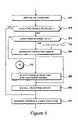
- FIG. 7shows the invention, including operations of extracting phase difference information, looking up candidate locations in an index and identifying highest scoring candidates, and calibration data including an index and phase difference profiles;
- FIG. 13details the index shown in FIG. 6 ;
- FIG. 22summarises operations for creating the calibration data shown in FIG. 7 , including a step of recording location profiles and a step of creating a location index;
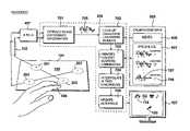
- the computer 102 shown in FIG. 1is detailed in FIG. 4 .
- a Pentium central processing unit (CPU) 401executes instructions held in one hundred and twenty-eight megabytes of main memory (RAM) 402 .
- the main memory 402also stores data which the processor may manipulate according to its instructions. Both data and instructions are stored on a hard disk drive 403 .
- the hard disk drive 403retains its contents when the computer 102 is switched off, so contents of the main memory 402 are refreshed from the hard disk drive 403 when the computer is switched on. Instructions and or data may be installed onto the hard disk drive 403 from a variety of sources.
- a CDROM drive 404reads CDROM, CDR or CDRW disks, including the CDROM 111 .
- a sound card 406receives signals from the touch pad 101 .
- the sound card 406has a stereo analogue to digital converter 407 , and the transducers 201 to 204 are connected to the stereo microphone input of the sound card 406 .
- the analogue to digital converter 407 in the sound card 406is configured to operate at a sample rate of 44.1 kHz with sixteen bits of precision for each of the left and right stereo channels.
- the sound card 406digitises incoming electrical signals from the touch pad 101 , and makes these digitised acoustic signals available to the processor 401 .
- the stream of samplesis temporarily stored in main memory, awaiting a burst of processor activity during which touch events are interpreted to update the user interface 108 .
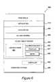
- the touch pad drivermay exist in several computer-readable forms: as intermediate serial data encoded upon a computer-readable medium such as the Internet or other network; as intermediate parallel compressed data stored temporarily in the main memory 402 or hard disk 403 of a computer 102 , or as a decoded executable set of instructions with associated data that is ready for installation or execution upon a computer with which a touch pad 101 is intended for use. It is further possible that a touch pad driver may be presented to a computer in a format that is only useful with an additional enabling sequence of codes that may be entered on the keyboard 113 or some other means of data entry.
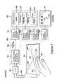
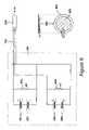
- acoustic signals arising from touch eventsare acquired by the touch pad 101 .
- Touch eventsare signified by an acoustic interaction between the touch pad 101 and an object 106 .
- the touch pad 101has an area 105 in which such touch events may be formed.
- Transducersacquire the acoustic signals at a plurality of different locations 201 , 202 , 203 and 204 in the surface 105 .
- a connecting cable 103supplies output signals that are representations of the said acoustic signals to an analogue to digital converter 407 .
- a plurality of transducers 201 , 203is configured so as to electrically combine acoustic signals from a plurality of said different locations 201 , 203 into a combined signal for said connecting cable 103 .
- a second plurality of transducers 202 , 204is similarly configured. Combined transducers are connected in antiphase 201 , 203 so as to electrically combine preferred components of the acquired acoustic signals, thereby avoiding potential analogue to digital converter overload during a tap event.
- the step 1403 of applying test features to the phase difference information to obtain the information score Sis detailed in FIG. 15 .
- a variable Dis set to zero.
- the first featureis selected, and a variable n is set to indicate the feature number.
- the array of phase difference information, PDIis indexed at the frequency 1307 specified by the current feature to identify the phase angle at that frequency in the phase difference information. This is indicated by the term PDI[Freq[n]].
- the phase angle 1308 , Phase[n]specified by the feature, is subtracted from this value, to provide a phase difference. Negative values are converted to positive, giving an absolute difference between the two phase angle values. A small difference indicates the phase difference information 706 matches the feature 1306 well.
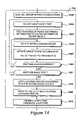
- the operation 703 of identifying the highest scoring candidate locations shown in FIG. 7is detailed in FIG. 18 .
- the first candidate locationis selected.
- the candidate location's phase difference profile 1201is correlated with the phase difference information 706 to obtain a correlation score for the candidate location. This correlation score is in the range ⁇ 1 to +1.
- a questionis asked as to whether another candidate location needs to be scored. If so, control is directed back to step 1801 .
- controlis directed to step 1804 , where the highest scoring candidate locations are identified. This reduces the number of candidate locations to twenty, as illustrated in FIG. 17 .
- a searchis performed around the highest scoring locations to see if any high scoring locations have been missed by the indexing process 702 .
- similarity scoresare obtained for the additional locations identified in step 1805 .
Landscapes
- Engineering & Computer Science (AREA)
- Physics & Mathematics (AREA)
- General Engineering & Computer Science (AREA)
- Theoretical Computer Science (AREA)
- Acoustics & Sound (AREA)
- Human Computer Interaction (AREA)
- General Physics & Mathematics (AREA)
- Position Input By Displaying (AREA)
- Length Measuring Devices Characterised By Use Of Acoustic Means (AREA)
- Electrophonic Musical Instruments (AREA)
- Oscillators With Electromechanical Resonators (AREA)
- Push-Button Switches (AREA)
- Stereophonic System (AREA)
- Measurement Of Velocity Or Position Using Acoustic Or Ultrasonic Waves (AREA)
- Braking Arrangements (AREA)
- Control Of Washing Machine And Dryer (AREA)
Abstract
Description
Claims (20)
Priority Applications (2)
| Application Number | Priority Date | Filing Date | Title |
|---|---|---|---|
| US12/182,734US8319752B2 (en) | 2002-02-06 | 2008-07-30 | Touch pad |
| US13/685,082US20130135261A1 (en) | 2002-02-06 | 2012-11-26 | Touch pad |
Applications Claiming Priority (11)
| Application Number | Priority Date | Filing Date | Title |
|---|---|---|---|
| GB0202772.0 | 2002-02-06 | ||
| GB0202772AGB2385125A (en) | 2002-02-06 | 2002-02-06 | Using vibrations generated by movement along a surface to determine position |
| GB0225107AGB0225107D0 (en) | 2002-10-29 | 2002-10-29 | Manufacture calibration |
| GB0225107.2 | 2002-10-29 | ||
| GB0225573.5 | 2002-11-02 | ||
| GB0225573AGB0225573D0 (en) | 2002-11-02 | 2002-11-02 | Sound source location |
| GB0226033.9 | 2002-11-07 | ||
| GB0226033AGB0226033D0 (en) | 2002-11-07 | 2002-11-07 | Computer input apparatus |
| GB0226037AGB0226037D0 (en) | 2002-11-07 | 2002-11-07 | Computer input apparatus |
| GB0226037.0 | 2002-11-07 | ||
| PCT/GB2003/000515WO2003067511A2 (en) | 2002-02-06 | 2003-02-05 | Touch pad |
Related Child Applications (1)
| Application Number | Title | Priority Date | Filing Date |
|---|---|---|---|
| US12/182,734ContinuationUS8319752B2 (en) | 2002-02-06 | 2008-07-30 | Touch pad |
Publications (2)
| Publication Number | Publication Date |
|---|---|
| US20050083313A1 US20050083313A1 (en) | 2005-04-21 |
| US7411581B2true US7411581B2 (en) | 2008-08-12 |
Family
ID=27739404
Family Applications (3)
| Application Number | Title | Priority Date | Filing Date |
|---|---|---|---|
| US10/502,969Expired - LifetimeUS7411581B2 (en) | 2002-02-06 | 2003-02-05 | Touch pad |
| US12/182,734Expired - Fee RelatedUS8319752B2 (en) | 2002-02-06 | 2008-07-30 | Touch pad |
| US13/685,082AbandonedUS20130135261A1 (en) | 2002-02-06 | 2012-11-26 | Touch pad |
Family Applications After (2)
| Application Number | Title | Priority Date | Filing Date |
|---|---|---|---|
| US12/182,734Expired - Fee RelatedUS8319752B2 (en) | 2002-02-06 | 2008-07-30 | Touch pad |
| US13/685,082AbandonedUS20130135261A1 (en) | 2002-02-06 | 2012-11-26 | Touch pad |
Country Status (7)
| Country | Link |
|---|---|
| US (3) | US7411581B2 (en) |
| EP (3) | EP2267582B1 (en) |
| AT (3) | ATE557337T1 (en) |
| AU (1) | AU2003244407A1 (en) |
| DE (2) | DE60335424D1 (en) |
| GB (1) | GB2401181A (en) |
| WO (1) | WO2003067511A2 (en) |
Cited By (52)
| Publication number | Priority date | Publication date | Assignee | Title |
|---|---|---|---|---|
| US20070132739A1 (en)* | 2005-12-14 | 2007-06-14 | Felder Matthew D | Touch screen driver and methods for use therewith |
| US20080158169A1 (en)* | 2007-01-03 | 2008-07-03 | Apple Computer, Inc. | Noise detection in multi-touch sensors |
| US20090008160A1 (en)* | 2007-07-02 | 2009-01-08 | Aroyan James L | Method and system for detecting touch events based on magnitude ratios |
| US20090009488A1 (en)* | 2007-07-02 | 2009-01-08 | D Souza Henry M | Method and system for detecting touch events based on redundant validation |
| US20090109191A1 (en)* | 2007-10-29 | 2009-04-30 | Felder Matthew D | Touch Screen Driver for Resolving Plural Contemporaneous Touches and Methods for Use Therewith |
| US20090122028A1 (en)* | 2005-04-13 | 2009-05-14 | Sensitive Object | Method For Determining The Location Of Impacts By Acoustic Imaging |
| US20110025649A1 (en)* | 2009-05-22 | 2011-02-03 | Hamid Sheikhzadeh Nadjar | Method and apparatus for detecting hold condition on an acoustic touch surface |
| US20110038114A1 (en)* | 2009-08-17 | 2011-02-17 | Apple Inc. | Housing as an i/o device |
| US20110037734A1 (en)* | 2009-08-17 | 2011-02-17 | Apple Inc. | Electronic device housing as acoustic input device |
| US20110156861A1 (en)* | 2009-12-31 | 2011-06-30 | Motorola, Inc. | Electronic Device Including a Wireless Actuator and a Method Thereof |
| US20110175813A1 (en)* | 2010-01-20 | 2011-07-21 | Apple Inc. | Piezo-based acoustic and capacitive detection |
| US20110199315A1 (en)* | 2010-02-15 | 2011-08-18 | Tyco Electronics Corporation | Touch panel that has an image layer and detects bending waves |
| US20120050230A1 (en)* | 2009-04-09 | 2012-03-01 | New Transducers Limited | Touch Sensitive Device |
| US8319746B1 (en) | 2011-07-22 | 2012-11-27 | Google Inc. | Systems and methods for removing electrical noise from a touchpad signal |
| US8515094B2 (en) | 2010-10-12 | 2013-08-20 | Hewlett-Packard Development Company, L.P. | Distributed signal processing systems and methods |
| CN103729098A (en)* | 2012-10-15 | 2014-04-16 | 圆展科技股份有限公司 | Acoustic touch device applied to electronic products and touch method thereof |
| US20140269194A1 (en)* | 2013-03-18 | 2014-09-18 | Inputek Inc. | Three Dimensional Touch by Acoustic Waves |
| US8904052B2 (en) | 2011-12-23 | 2014-12-02 | Apple Inc. | Combined input port |
| TWI472992B (en)* | 2012-10-04 | 2015-02-11 | Aver Information Inc | Touching voice control device and method applied to electronic apparatus |
| US20150123923A1 (en)* | 2013-11-05 | 2015-05-07 | N-Trig Ltd. | Stylus tilt tracking with a digitizer |
| US9176623B2 (en) | 2010-12-22 | 2015-11-03 | Elo Touch Solutions, Inc. | Method and a touch sensing device for implementing the method |
| US9189109B2 (en) | 2012-07-18 | 2015-11-17 | Sentons Inc. | Detection of type of object used to provide a touch contact input |
| US9342192B2 (en) | 2010-12-22 | 2016-05-17 | Elo Touch Solutions, Inc. | Method and a touch sensing device for implementing the method |
| US9348468B2 (en) | 2013-06-07 | 2016-05-24 | Sentons Inc. | Detecting multi-touch inputs |
| US9449476B2 (en) | 2011-11-18 | 2016-09-20 | Sentons Inc. | Localized haptic feedback |
| US9459715B1 (en) | 2013-09-20 | 2016-10-04 | Sentons Inc. | Using spectral control in detecting touch input |
| US9477350B2 (en) | 2011-04-26 | 2016-10-25 | Sentons Inc. | Method and apparatus for active ultrasonic touch devices |
| US9513727B2 (en) | 2012-07-18 | 2016-12-06 | Sentons Inc. | Touch input surface microphone |
| US9524063B2 (en) | 2012-07-18 | 2016-12-20 | Sentons Inc. | Detection of a number of touch contacts of a multi-touch input |
| US9563239B2 (en) | 2012-09-10 | 2017-02-07 | Apple Inc. | Internal computer assembly features and methods |
| US9588552B2 (en) | 2013-09-11 | 2017-03-07 | Sentons Inc. | Attaching electrical components using non-conductive adhesive |
| US9594450B2 (en) | 2011-11-18 | 2017-03-14 | Sentons Inc. | Controlling audio volume using touch input force |
| US9639213B2 (en) | 2011-04-26 | 2017-05-02 | Sentons Inc. | Using multiple signals to detect touch input |
| US20170255327A1 (en)* | 2016-03-03 | 2017-09-07 | Martin J. SIMMONS | Touch Sensor Mode Transitioning |
| US9756927B2 (en) | 2011-11-30 | 2017-09-12 | Apple Inc. | Mounting system for portable electronic device |
| US9857920B2 (en)* | 2010-02-02 | 2018-01-02 | Samsung Electronics Co., Ltd. | Method and apparatus for providing user interface using acoustic signal, and device including user interface |
| US9880671B2 (en) | 2013-10-08 | 2018-01-30 | Sentons Inc. | Damping vibrational wave reflections |
| US10048811B2 (en) | 2015-09-18 | 2018-08-14 | Sentons Inc. | Detecting touch input provided by signal transmitting stylus |
| US10126877B1 (en) | 2017-02-01 | 2018-11-13 | Sentons Inc. | Update of reference data for touch input detection |
| WO2018211281A1 (en) | 2017-05-19 | 2018-11-22 | Sintef Tto As | Touch-based input device |
| US10198097B2 (en) | 2011-04-26 | 2019-02-05 | Sentons Inc. | Detecting touch input force |
| US10235004B1 (en) | 2011-11-18 | 2019-03-19 | Sentons Inc. | Touch input detector with an integrated antenna |
| US10296144B2 (en) | 2016-12-12 | 2019-05-21 | Sentons Inc. | Touch input detection with shared receivers |
| US10585522B2 (en) | 2017-02-27 | 2020-03-10 | Sentons Inc. | Detection of non-touch inputs using a signature |
| US10908741B2 (en) | 2016-11-10 | 2021-02-02 | Sentons Inc. | Touch input detection along device sidewall |
| US10984210B2 (en) | 2018-12-10 | 2021-04-20 | Samsung Electronics Co., Ltd. | Fingerprint sensor of electronic device |
| US11009989B2 (en)* | 2018-08-21 | 2021-05-18 | Qeexo, Co. | Recognizing and rejecting unintentional touch events associated with a touch sensitive device |
| US11009411B2 (en) | 2017-08-14 | 2021-05-18 | Sentons Inc. | Increasing sensitivity of a sensor using an encoded signal |
| US11327599B2 (en) | 2011-04-26 | 2022-05-10 | Sentons Inc. | Identifying a contact type |
| US11580829B2 (en) | 2017-08-14 | 2023-02-14 | Sentons Inc. | Dynamic feedback for haptics |
| US20240111384A1 (en)* | 2022-09-30 | 2024-04-04 | Bang & Olufsen | Touch-originating sound profile sensing systems and methods |
| US12166911B2 (en) | 2021-03-02 | 2024-12-10 | Apple Inc. | Handheld electronic device |
Families Citing this family (96)
| Publication number | Priority date | Publication date | Assignee | Title |
|---|---|---|---|---|
| US7157649B2 (en) | 1999-12-23 | 2007-01-02 | New Transducers Limited | Contact sensitive device |
| GB0116310D0 (en) | 2001-07-04 | 2001-08-29 | New Transducers Ltd | Contact sensitive device |
| EP2267582B1 (en)* | 2002-02-06 | 2012-05-09 | Soundtouch Limited | Touch pad |
| FR2841022B1 (en) | 2002-06-12 | 2004-08-27 | Centre Nat Rech Scient | METHOD FOR LOCATING AN IMPACT ON A SURFACE AND DEVICE FOR IMPLEMENTING SAID METHOD |
| US6871149B2 (en) | 2002-12-06 | 2005-03-22 | New Transducers Limited | Contact sensitive device |
| WO2005055028A2 (en)* | 2003-12-05 | 2005-06-16 | Rupprecht & Partner | Alphanumeric input unit |
| FR2874274B1 (en)* | 2004-08-11 | 2007-07-20 | Sensitive Object | METHOD FOR LOCATING AN IMPACT ON A SURFACE AND DEVICE FOR IMPLEMENTING SAID METHOD |
| US7515138B2 (en) | 2004-10-01 | 2009-04-07 | 3M Innovative Properties Company | Distinguishing vibration signals from interference in vibration sensing touch input devices |
| CN101095097B (en) | 2004-12-29 | 2012-01-25 | 传感器公司 | Method and device for determining the position of impacts |
| CN100368975C (en)* | 2004-12-31 | 2008-02-13 | 义隆电子股份有限公司 | Capacitive touch pad and detection method thereof |
| US7928964B2 (en) | 2005-04-22 | 2011-04-19 | Microsoft Corporation | Touch input data handling |
| US7986307B2 (en)* | 2005-04-22 | 2011-07-26 | Microsoft Corporation | Mechanism for allowing applications to filter out or opt into tablet input |
| US20060267958A1 (en)* | 2005-04-22 | 2006-11-30 | Microsoft Corporation | Touch Input Programmatical Interfaces |
| US7683890B2 (en) | 2005-04-28 | 2010-03-23 | 3M Innovative Properties Company | Touch location determination using bending mode sensors and multiple detection techniques |
| FR2886585B1 (en)* | 2005-06-07 | 2009-03-13 | Peugeot Citroen Automobiles Sa | DEVICE FOR MONITORING AND / OR CONTROLLING EQUIPMENT OF A MOTOR VEHICLE |
| FR2887658B1 (en)* | 2005-06-28 | 2007-09-14 | Peugeot Citroen Automobiles Sa | DEVICE FOR MONITORING EQUIPMENT OF A MOTOR VEHICLE WITH TOUCH SLAB AND CONTROL BUTTONS |
| US20070109279A1 (en)* | 2005-11-15 | 2007-05-17 | Tyco Electronics Raychem Gmbh | Method and apparatus for identifying locations of ambiguous multiple touch events |
| US7593005B2 (en)* | 2005-12-13 | 2009-09-22 | Awr Consulting Inc. | Touch detection system |
| US7907129B2 (en) | 2005-12-14 | 2011-03-15 | Research In Motion Limited | Handheld electronic device having virtual keypad input device, and associated method |
| US7800596B2 (en) | 2005-12-14 | 2010-09-21 | Research In Motion Limited | Handheld electronic device having virtual navigational input device, and associated method |
| EP1798635A1 (en)* | 2005-12-14 | 2007-06-20 | Research In Motion Limited | Handheld electronic device having virtual keypad input device, and associated method |
| ATE545082T1 (en)* | 2005-12-14 | 2012-02-15 | Research In Motion Ltd | PORTABLE ELECTRONIC DEVICE WITH VIRTUAL NAVIGATION INPUT AND CORRESPONDING METHOD |
| US8692809B2 (en) | 2006-07-06 | 2014-04-08 | Elo Touch Solutions, Inc. | Auto-gain switching module for acoustic touch systems |
| EA014210B1 (en) | 2006-10-25 | 2010-10-29 | Сенситив Обджект | Automatic gain control circuit, system including such circuit and method for automatic gain control |
| GB2459799B (en)* | 2007-01-16 | 2010-03-17 | N trig ltd | System and method for calibration of a capacitive touch digitizer system |
| FR2916545B1 (en)* | 2007-05-23 | 2009-11-20 | Inst Pour Le Dev De La Science | METHOD FOR LOCATING A TOUCH ON A SURFACE AND DEVICE FOR IMPLEMENTING SAID METHOD |
| WO2008146098A1 (en)* | 2007-05-28 | 2008-12-04 | Sensitive Object | Method for determining the position of an excitation on a surface and device for implementing such a method |
| US8493332B2 (en)* | 2007-06-21 | 2013-07-23 | Elo Touch Solutions, Inc. | Method and system for calibrating an acoustic touchscreen |
| EP2017703A1 (en)* | 2007-07-09 | 2009-01-21 | Sensitive Object | Touch control system and method for localising an excitation |
| US20130217491A1 (en)* | 2007-11-02 | 2013-08-22 | Bally Gaming, Inc. | Virtual button deck with sensory feedback |
| EP2073106B1 (en)* | 2007-12-21 | 2012-02-08 | Tyco Electronics Services GmbH | Method for determining the locations of at least two impacts |
| JP5411425B2 (en)* | 2007-12-25 | 2014-02-12 | 任天堂株式会社 | GAME PROGRAM, GAME DEVICE, GAME SYSTEM, AND GAME PROCESSING METHOD |
| WO2010007813A1 (en)* | 2008-07-16 | 2010-01-21 | 株式会社ソニー・コンピュータエンタテインメント | Mobile type image display device, method for controlling the same and information memory medium |
| US8743091B2 (en)* | 2008-07-31 | 2014-06-03 | Apple Inc. | Acoustic multi-touch sensor panel |
| US8605037B2 (en)* | 2008-10-21 | 2013-12-10 | Atmel Corporation | Noise reduction in capacitive touch sensors |
| US20100220063A1 (en)* | 2009-02-27 | 2010-09-02 | Panasonic Corporation | System and methods for calibratable translation of position |
| EP2270635A1 (en)* | 2009-06-23 | 2011-01-05 | Sensitive Object | Touch sensing method and device |
| EP2270636A1 (en)* | 2009-06-23 | 2011-01-05 | Sensitive Object | A method and a touch sensing device for implementing the method |
| CA2765970A1 (en) | 2009-06-23 | 2010-12-29 | Tyco Electronics Services Gmbh | A method and a touch sensing device for implementing the method |
| JP2011028555A (en)* | 2009-07-27 | 2011-02-10 | Sony Corp | Information processor and information processing method |
| US9696856B2 (en) | 2009-09-29 | 2017-07-04 | Elo Touch Solutions, Inc. | Method and apparatus for detecting simultaneous touch events on a bending-wave touchscreen |
| KR101654008B1 (en)* | 2009-10-09 | 2016-09-09 | 삼성전자주식회사 | Mobile device using acoustic signal processing and acoustic signal processing method performed by the mobile device |
| US8982103B2 (en) | 2009-10-27 | 2015-03-17 | Stmicroelectronics S.R.L. | Method for determining the position of a contact on a touch panel and corresponding system |
| US8194051B2 (en)* | 2009-12-15 | 2012-06-05 | Silicon Integrated Systems Corp. | Multiple fingers touch sensing method using matching algorithm |
| US20110231796A1 (en)* | 2010-02-16 | 2011-09-22 | Jose Manuel Vigil | Methods for navigating a touch screen device in conjunction with gestures |
| TW201203041A (en)* | 2010-03-05 | 2012-01-16 | Canatu Oy | A touch sensitive film and a touch sensing device |
| TWI421752B (en)* | 2010-08-06 | 2014-01-01 | Quanta Comp Inc | Optical touch system |
| US9459733B2 (en)* | 2010-08-27 | 2016-10-04 | Inputdynamics Limited | Signal processing systems |
| US20120249419A1 (en)* | 2011-03-30 | 2012-10-04 | Bronner Sr Dennis M | Thumb mountable cursor control and input device |
| US9507454B1 (en)* | 2011-09-19 | 2016-11-29 | Parade Technologies, Ltd. | Enhanced linearity of gestures on a touch-sensitive surface |
| TW201316240A (en)* | 2011-10-06 | 2013-04-16 | Rich Ip Technology Inc | Touch processing method and system using graphic user interface image |
| KR102027601B1 (en) | 2011-10-18 | 2019-10-01 | 카네기 멜론 유니버시티 | Method and apparatus for classifying touch events on a touch sensitive surface |
| US20130147743A1 (en)* | 2011-12-12 | 2013-06-13 | Lester F. Ludwig | Spherical Touch Sensors and Signal/Power Architectures for Trackballs, Globes, Displays, and Other Applications |
| CN105700742B (en)* | 2012-04-09 | 2019-02-19 | 禾瑞亚科技股份有限公司 | Method and device for position detection |
| US9030839B2 (en) | 2012-10-18 | 2015-05-12 | Apple Inc. | Track pad acoustic features related to a portable computer |
| US9134856B2 (en)* | 2013-01-08 | 2015-09-15 | Sony Corporation | Apparatus and method for controlling a user interface of a device based on vibratory signals |
| US9019244B2 (en) | 2013-02-28 | 2015-04-28 | Qeexo, Co. | Input tools having viobro-acoustically distinct regions and computing device for use with the same |
| US9717459B2 (en) | 2013-03-04 | 2017-08-01 | Anne Bibiana Sereno | Touch sensitive system and method for cognitive and behavioral testing and evaluation |
| KR20140114766A (en) | 2013-03-19 | 2014-09-29 | 퀵소 코 | Method and device for sensing touch inputs |
| US9013452B2 (en) | 2013-03-25 | 2015-04-21 | Qeexo, Co. | Method and system for activating different interactive functions using different types of finger contacts |
| US9612689B2 (en) | 2015-02-02 | 2017-04-04 | Qeexo, Co. | Method and apparatus for classifying a touch event on a touchscreen as related to one of multiple function generating interaction layers and activating a function in the selected interaction layer |
| US10599250B2 (en) | 2013-05-06 | 2020-03-24 | Qeexo, Co. | Using finger touch types to interact with electronic devices |
| CN104281338A (en)* | 2013-07-03 | 2015-01-14 | 向火平 | OGS manufacturing process and single-layer capacitive touch panel |
| CN110413190B (en) | 2014-02-12 | 2022-08-23 | 齐科斯欧公司 | Determining pitch and yaw for touch screen interaction |
| WO2015167511A2 (en)* | 2014-04-30 | 2015-11-05 | Empire Technology Development Llc | Adjusting tap position on touch screen |
| US9329715B2 (en) | 2014-09-11 | 2016-05-03 | Qeexo, Co. | Method and apparatus for differentiating touch screen users based on touch event analysis |
| US11619983B2 (en) | 2014-09-15 | 2023-04-04 | Qeexo, Co. | Method and apparatus for resolving touch screen ambiguities |
| US9864453B2 (en) | 2014-09-22 | 2018-01-09 | Qeexo, Co. | Method and apparatus for improving accuracy of touch screen event analysis by use of edge classification |
| US10606417B2 (en) | 2014-09-24 | 2020-03-31 | Qeexo, Co. | Method for improving accuracy of touch screen event analysis by use of spatiotemporal touch patterns |
| US10712858B2 (en) | 2014-09-25 | 2020-07-14 | Qeexo, Co. | Method and apparatus for classifying contacts with a touch sensitive device |
| US10095402B2 (en)* | 2014-10-01 | 2018-10-09 | Qeexo, Co. | Method and apparatus for addressing touch discontinuities |
| EP3065043A1 (en)* | 2015-03-02 | 2016-09-07 | Nxp B.V. | Mobile device |
| DE102015205950B4 (en) | 2015-04-01 | 2017-02-02 | Volkswagen Aktiengesellschaft | Apparatus, method and computer program for detecting acoustic control instructions |
| WO2017004262A1 (en) | 2015-07-01 | 2017-01-05 | Qeexo, Co. | Determining pitch for proximity sensitive interactions |
| US10642404B2 (en) | 2015-08-24 | 2020-05-05 | Qeexo, Co. | Touch sensitive device with multi-sensor stream synchronized data |
| US10671222B2 (en) | 2015-09-30 | 2020-06-02 | Apple Inc. | Touch sensor pattern for edge input detection |
| US11036318B2 (en) | 2015-09-30 | 2021-06-15 | Apple Inc. | Capacitive touch or proximity detection for crown |
| US20170242527A1 (en)* | 2016-02-18 | 2017-08-24 | Knowles Electronics, Llc | System and method for detecting touch on a surface of a touch sensitive device |
| US11402950B2 (en) | 2016-07-29 | 2022-08-02 | Apple Inc. | Methodology and application of acoustic touch detection |
| US11157115B2 (en) | 2017-03-31 | 2021-10-26 | Apple Inc. | Composite cover material for sensitivity improvement of ultrasonic touch screens |
| US10606418B2 (en) | 2017-03-31 | 2020-03-31 | Apple Inc. | Ultrasonic touch detection on stylus |
| US11144158B2 (en) | 2017-05-24 | 2021-10-12 | Apple Inc. | Differential acoustic touch and force sensing |
| US11334196B2 (en) | 2017-05-24 | 2022-05-17 | Apple Inc. | System and method for acoustic touch and force sensing |
| CN108932084B (en) | 2017-05-24 | 2022-05-27 | 苹果公司 | Systems and methods for acoustic touch and force sensing |
| US10949030B2 (en) | 2017-09-26 | 2021-03-16 | Apple Inc. | Shear-poled curved piezoelectric material |
| CN109753191B (en)* | 2017-11-03 | 2022-07-26 | 迪尔阿扣基金两合公司 | Acoustic touch system |
| US10802651B2 (en) | 2018-01-30 | 2020-10-13 | Apple Inc. | Ultrasonic touch detection through display |
| US11366552B2 (en) | 2018-02-06 | 2022-06-21 | Apple, Inc. | Ultrasonic polarizer |
| US10725573B2 (en) | 2018-08-06 | 2020-07-28 | Apple Inc. | Annular piezoelectric structure for ultrasonic touch sensing |
| EP3547321A1 (en) | 2018-08-24 | 2019-10-02 | Siemens Healthcare GmbH | Method and system for displaying clinical information on a screen of a wearable device |
| DE102018216662A1 (en)* | 2018-09-27 | 2020-04-02 | Continental Automotive Gmbh | Dashboard layout, procedure and use |
| US10942603B2 (en) | 2019-05-06 | 2021-03-09 | Qeexo, Co. | Managing activity states of an application processor in relation to touch or hover interactions with a touch sensitive device |
| US11980792B2 (en) | 2019-06-05 | 2024-05-14 | Qeexo, Co. | Method and apparatus for calibrating a user activity model used by a mobile device |
| US11231815B2 (en) | 2019-06-28 | 2022-01-25 | Qeexo, Co. | Detecting object proximity using touch sensitive surface sensing and ultrasonic sensing |
| US11592423B2 (en) | 2020-01-29 | 2023-02-28 | Qeexo, Co. | Adaptive ultrasonic sensing techniques and systems to mitigate interference |
| US12216851B2 (en) | 2022-09-23 | 2025-02-04 | Apple Inc. | Multi-directional texture based input device |
Citations (39)
| Publication number | Priority date | Publication date | Assignee | Title |
|---|---|---|---|---|
| DE3027923A1 (en) | 1980-07-23 | 1982-02-04 | Siemens Ag | Position location of contact point on data panel - has signals generated by pointer contact detected by electroacoustic converters and evaluated by digital circuit |
| US4317227A (en) | 1980-06-09 | 1982-02-23 | Zenith Radio Corporation | Multi-mode automatic channel frequency synthesis system |
| US4592034A (en)* | 1982-11-15 | 1986-05-27 | Cornell Research Foundation, Inc. | Acoustic emission source location on plate-like structures using a small array of transducers |
| US4644100A (en) | 1985-03-22 | 1987-02-17 | Zenith Electronics Corporation | Surface acoustic wave touch panel system |
| FR2595744A1 (en) | 1986-03-14 | 1987-09-18 | Colliot Georges | Key and corresponding electroacoustic lock |
| US4880665A (en)* | 1987-01-20 | 1989-11-14 | Zenith Electronics Corporation | Touch control arrangement for graphics display apparatus having saw reflectors of frit composition |
| US5059959A (en)* | 1985-06-03 | 1991-10-22 | Seven Oaks Corporation | Cursor positioning method and apparatus |
| EP0474232A2 (en) | 1990-09-06 | 1992-03-11 | Sharp Kabushiki Kaisha | Transparent touch-sensitive panel |
| US5194852A (en) | 1986-12-01 | 1993-03-16 | More Edward S | Electro-optic slate for direct entry and display and/or storage of hand-entered textual and graphic information |
| DE4143364A1 (en) | 1991-09-09 | 1993-09-30 | Roman Koller | Contact detection or function, e.g. for entering data by hand, esp. into form fields, - involves sensing vibrations between pencil and recording surface |
| US5404458A (en) | 1991-10-10 | 1995-04-04 | International Business Machines Corporation | Recognizing the cessation of motion of a pointing device on a display by comparing a group of signals to an anchor point |
| US5412189A (en) | 1992-12-21 | 1995-05-02 | International Business Machines Corporation | Touch screen apparatus with tactile information |
| GB2301217A (en) | 1995-05-26 | 1996-11-27 | Nokia Mobile Phones Ltd | Display driver |
| US5591945A (en)* | 1995-04-19 | 1997-01-07 | Elo Touchsystems, Inc. | Acoustic touch position sensor using higher order horizontally polarized shear wave propagation |
| US5628031A (en) | 1993-07-19 | 1997-05-06 | Elonex Ip Holdings Ltd. | Personal digital assistant module implemented as a low-profile printed circuit assembly having a rigid substrate wherein IC devices are mounted within openings wholly between opposite plane surfaces of the rigid substrate |
| US5638093A (en) | 1993-12-07 | 1997-06-10 | Seiko Epson Corporation | Touch panel input device and control method thereof |
| US5691959A (en) | 1994-04-06 | 1997-11-25 | Fujitsu, Ltd. | Stylus position digitizer using acoustic waves |
| FR2757659A1 (en) | 1996-12-20 | 1998-06-26 | Sextant Avionique | METHOD FOR OPTIMIZING THE DETECTION OF THE ATTACHMENT POINT OF A CAPACITIVE TOUCH SURFACE |
| US5856820A (en) | 1995-02-24 | 1999-01-05 | The Whitaker Corporation | Laminated acoustic wave touch panel |
| WO1999038149A1 (en) | 1998-01-26 | 1999-07-29 | Wayne Westerman | Method and apparatus for integrating manual input |
| JPH11327772A (en) | 1998-05-07 | 1999-11-30 | Ricoh Co Ltd | Ultrasonic touch panel |
| US6161434A (en) | 1996-06-13 | 2000-12-19 | Fink; Mathias | Method and device for detecting and locating a reflecting sound source |
| US6167165A (en) | 1998-11-25 | 2000-12-26 | Eastman Kodak Company | Method for adjusting image detail to compensate for an applied tone scale |
| WO2001043063A1 (en) | 1999-12-06 | 2001-06-14 | Soundtouch Limited. | Inputting data |
| US20010006006A1 (en) | 1999-12-23 | 2001-07-05 | Hill Nicholas P.R. | Contact sensitive device |
| WO2001048684A2 (en) | 1999-12-23 | 2001-07-05 | New Transducers Limited | Contact sensitive device |
| FR2811107A1 (en) | 2000-06-29 | 2002-01-04 | Jean Pierre Nikolovski | PRECISION INTERACTIVE ACOUSTIC PLATE |
| US20020050983A1 (en)* | 2000-09-26 | 2002-05-02 | Qianjun Liu | Method and apparatus for a touch sensitive system employing spread spectrum technology for the operation of one or more input devices |
| WO2003005292A1 (en) | 2001-07-04 | 2003-01-16 | New Transducers Limited | Contact sensitive device |
| US6535147B1 (en)* | 1998-11-16 | 2003-03-18 | The Whitaker Corporation | Segmented gain controller |
| US6549193B1 (en) | 1998-10-09 | 2003-04-15 | 3M Innovative Properties Company | Touch panel with improved linear response and minimal border width electrode pattern |
| US6555235B1 (en) | 2000-07-06 | 2003-04-29 | 3M Innovative Properties Co. | Touch screen system |
| US20030217873A1 (en) | 2002-05-24 | 2003-11-27 | Massachusetts Institute Of Technology | Systems and methods for tracking impacts |
| US6724373B1 (en) | 2000-01-05 | 2004-04-20 | Brother International Corporation | Electronic whiteboard hot zones for controlling local and remote personal computer functions |
| US6738051B2 (en) | 2001-04-06 | 2004-05-18 | 3M Innovative Properties Company | Frontlit illuminated touch panel |
| US6741237B1 (en)* | 2001-08-23 | 2004-05-25 | Rockwell Automation Technologies, Inc. | Touch screen |
| US20050134574A1 (en)* | 2003-12-18 | 2005-06-23 | Hill Nicholas P.R. | Piezoelectric transducer |
| US7049960B2 (en) | 2003-12-29 | 2006-05-23 | Lenovo (Singapore) Pte. Ltd | Method and system for locating objects |
| US7116315B2 (en) | 2003-03-14 | 2006-10-03 | Tyco Electronics Corporation | Water tolerant touch sensor |
Family Cites Families (6)
| Publication number | Priority date | Publication date | Assignee | Title |
|---|---|---|---|---|
| IT1257164B (en) | 1992-10-23 | 1996-01-05 | Ist Trentino Di Cultura | PROCEDURE FOR LOCATING A SPEAKER AND THE ACQUISITION OF A VOICE MESSAGE, AND ITS SYSTEM. |
| US6292177B1 (en)* | 1997-03-05 | 2001-09-18 | Tidenet, Inc. | Marking device for electronic presentation board |
| US6078315A (en)* | 1997-11-03 | 2000-06-20 | Microtouch System Inc. | Touch panel using acoustic wave reflection |
| FR2787608B1 (en)* | 1998-12-22 | 2001-03-30 | Clic Choc Multimedia | INTERACTIVE ACOUSTIC PLATE WITH IMPROVED SIGNAL PROCESSING MEANS |
| US6727896B2 (en)* | 2001-08-01 | 2004-04-27 | Microsoft Corporation | Correction of alignment and linearity errors in a stylus input system |
| EP2267582B1 (en)* | 2002-02-06 | 2012-05-09 | Soundtouch Limited | Touch pad |
- 2003
- 2003-02-05EPEP10010794Apatent/EP2267582B1/ennot_activeExpired - Lifetime
- 2003-02-05DEDE60335424Tpatent/DE60335424D1/ennot_activeExpired - Lifetime
- 2003-02-05USUS10/502,969patent/US7411581B2/ennot_activeExpired - Lifetime
- 2003-02-05ATAT10010794Tpatent/ATE557337T1/enactive
- 2003-02-05ATAT07016328Tpatent/ATE491984T1/ennot_activeIP Right Cessation
- 2003-02-05ATAT03737370Tpatent/ATE373262T1/ennot_activeIP Right Cessation
- 2003-02-05EPEP07016328Apatent/EP1852772B1/ennot_activeExpired - Lifetime
- 2003-02-05EPEP03737370Apatent/EP1481359B9/ennot_activeExpired - Lifetime
- 2003-02-05WOPCT/GB2003/000515patent/WO2003067511A2/enactiveIP Right Grant
- 2003-02-05AUAU2003244407Apatent/AU2003244407A1/ennot_activeAbandoned
- 2003-02-05DEDE60316259Tpatent/DE60316259T2/ennot_activeExpired - Lifetime
- 2004
- 2004-07-30GBGB0416978Apatent/GB2401181A/ennot_activeWithdrawn
- 2008
- 2008-07-30USUS12/182,734patent/US8319752B2/ennot_activeExpired - Fee Related
- 2012
- 2012-11-26USUS13/685,082patent/US20130135261A1/ennot_activeAbandoned
Patent Citations (46)
| Publication number | Priority date | Publication date | Assignee | Title |
|---|---|---|---|---|
| US4317227A (en) | 1980-06-09 | 1982-02-23 | Zenith Radio Corporation | Multi-mode automatic channel frequency synthesis system |
| DE3027923A1 (en) | 1980-07-23 | 1982-02-04 | Siemens Ag | Position location of contact point on data panel - has signals generated by pointer contact detected by electroacoustic converters and evaluated by digital circuit |
| US4592034A (en)* | 1982-11-15 | 1986-05-27 | Cornell Research Foundation, Inc. | Acoustic emission source location on plate-like structures using a small array of transducers |
| US4644100A (en) | 1985-03-22 | 1987-02-17 | Zenith Electronics Corporation | Surface acoustic wave touch panel system |
| US5059959A (en)* | 1985-06-03 | 1991-10-22 | Seven Oaks Corporation | Cursor positioning method and apparatus |
| FR2595744A1 (en) | 1986-03-14 | 1987-09-18 | Colliot Georges | Key and corresponding electroacoustic lock |
| US5194852A (en) | 1986-12-01 | 1993-03-16 | More Edward S | Electro-optic slate for direct entry and display and/or storage of hand-entered textual and graphic information |
| US4880665A (en)* | 1987-01-20 | 1989-11-14 | Zenith Electronics Corporation | Touch control arrangement for graphics display apparatus having saw reflectors of frit composition |
| US5717432A (en) | 1990-09-06 | 1998-02-10 | Sharp Kabushiki Kaisha | Signal input device |
| EP0474232A2 (en) | 1990-09-06 | 1992-03-11 | Sharp Kabushiki Kaisha | Transparent touch-sensitive panel |
| DE4143364A1 (en) | 1991-09-09 | 1993-09-30 | Roman Koller | Contact detection or function, e.g. for entering data by hand, esp. into form fields, - involves sensing vibrations between pencil and recording surface |
| US5404458A (en) | 1991-10-10 | 1995-04-04 | International Business Machines Corporation | Recognizing the cessation of motion of a pointing device on a display by comparing a group of signals to an anchor point |
| US5412189A (en) | 1992-12-21 | 1995-05-02 | International Business Machines Corporation | Touch screen apparatus with tactile information |
| US5628031A (en) | 1993-07-19 | 1997-05-06 | Elonex Ip Holdings Ltd. | Personal digital assistant module implemented as a low-profile printed circuit assembly having a rigid substrate wherein IC devices are mounted within openings wholly between opposite plane surfaces of the rigid substrate |
| US5638093A (en) | 1993-12-07 | 1997-06-10 | Seiko Epson Corporation | Touch panel input device and control method thereof |
| US5691959A (en) | 1994-04-06 | 1997-11-25 | Fujitsu, Ltd. | Stylus position digitizer using acoustic waves |
| US5856820A (en) | 1995-02-24 | 1999-01-05 | The Whitaker Corporation | Laminated acoustic wave touch panel |
| US6723929B2 (en) | 1995-04-19 | 2004-04-20 | Elo Touchsystems, Inc. | Acoustic condition sensor employing a plurality of mutually non-orthogonal waves |
| US5591945A (en)* | 1995-04-19 | 1997-01-07 | Elo Touchsystems, Inc. | Acoustic touch position sensor using higher order horizontally polarized shear wave propagation |
| US5986224A (en)* | 1995-04-19 | 1999-11-16 | Elo Touchsystems, Inc. | Acoustic condition sensor employing a plurality of mutually non-orthogonal waves |
| GB2301217A (en) | 1995-05-26 | 1996-11-27 | Nokia Mobile Phones Ltd | Display driver |
| US6161434A (en) | 1996-06-13 | 2000-12-19 | Fink; Mathias | Method and device for detecting and locating a reflecting sound source |
| FR2757659A1 (en) | 1996-12-20 | 1998-06-26 | Sextant Avionique | METHOD FOR OPTIMIZING THE DETECTION OF THE ATTACHMENT POINT OF A CAPACITIVE TOUCH SURFACE |
| US6404353B1 (en) | 1996-12-20 | 2002-06-11 | Sextant Avionique | Method for optimizing the detection of the contact point of tactile capacitance surface |
| WO1999038149A1 (en) | 1998-01-26 | 1999-07-29 | Wayne Westerman | Method and apparatus for integrating manual input |
| JPH11327772A (en) | 1998-05-07 | 1999-11-30 | Ricoh Co Ltd | Ultrasonic touch panel |
| US6392167B1 (en) | 1998-05-07 | 2002-05-21 | Ricoh Company, Ltd. | Acoustic touch position sensing system with large touch sensing surface |
| US6549193B1 (en) | 1998-10-09 | 2003-04-15 | 3M Innovative Properties Company | Touch panel with improved linear response and minimal border width electrode pattern |
| US6535147B1 (en)* | 1998-11-16 | 2003-03-18 | The Whitaker Corporation | Segmented gain controller |
| US6167165A (en) | 1998-11-25 | 2000-12-26 | Eastman Kodak Company | Method for adjusting image detail to compensate for an applied tone scale |
| WO2001043063A1 (en) | 1999-12-06 | 2001-06-14 | Soundtouch Limited. | Inputting data |
| US20010006006A1 (en) | 1999-12-23 | 2001-07-05 | Hill Nicholas P.R. | Contact sensitive device |
| WO2001048684A2 (en) | 1999-12-23 | 2001-07-05 | New Transducers Limited | Contact sensitive device |
| US6724373B1 (en) | 2000-01-05 | 2004-04-20 | Brother International Corporation | Electronic whiteboard hot zones for controlling local and remote personal computer functions |
| FR2811107A1 (en) | 2000-06-29 | 2002-01-04 | Jean Pierre Nikolovski | PRECISION INTERACTIVE ACOUSTIC PLATE |
| US20030066692A1 (en) | 2000-06-29 | 2003-04-10 | Fabrice Devige | Accurate interactive acoustic plate |
| US6555235B1 (en) | 2000-07-06 | 2003-04-29 | 3M Innovative Properties Co. | Touch screen system |
| US20020050983A1 (en)* | 2000-09-26 | 2002-05-02 | Qianjun Liu | Method and apparatus for a touch sensitive system employing spread spectrum technology for the operation of one or more input devices |
| US6738051B2 (en) | 2001-04-06 | 2004-05-18 | 3M Innovative Properties Company | Frontlit illuminated touch panel |
| WO2003005292A1 (en) | 2001-07-04 | 2003-01-16 | New Transducers Limited | Contact sensitive device |
| US6922642B2 (en) | 2001-07-04 | 2005-07-26 | New Transducers Limited | Contact sensitive device |
| US6741237B1 (en)* | 2001-08-23 | 2004-05-25 | Rockwell Automation Technologies, Inc. | Touch screen |
| US20030217873A1 (en) | 2002-05-24 | 2003-11-27 | Massachusetts Institute Of Technology | Systems and methods for tracking impacts |
| US7116315B2 (en) | 2003-03-14 | 2006-10-03 | Tyco Electronics Corporation | Water tolerant touch sensor |
| US20050134574A1 (en)* | 2003-12-18 | 2005-06-23 | Hill Nicholas P.R. | Piezoelectric transducer |
| US7049960B2 (en) | 2003-12-29 | 2006-05-23 | Lenovo (Singapore) Pte. Ltd | Method and system for locating objects |
Non-Patent Citations (11)
| Title |
|---|
| Draeger et al, 1999, "One-channel time-reversal in Chaotic Cavities: Experimental Results," J. Accoust. Soc. Am. 105(2):618-625. |
| Fink, M., "Time-Reversed Acoustics,", 1999, Scientific American, Nov. 1999, pp. 91-97. |
| Ing, R.K. et al. "Time-Reversed Lamb Waves," 1998, IEEE Transactions on Ultrasonics, Ferroelectrics, and Frequency Control, vol. 45, pp. 1032-1043. |
| Ing, R.K. et al. Dynamic Foucusing Using a Unique Transducer and Time Reversal Process, 2001, The 8th International Congress on Sound and Vibration, Jul. 2-6, 2001, Hong Kong. |
| Ing, R.K. et al. Ultrasonic Imaging Using Spatial-Temporal Matched Field (STMF) Processing-Applications to Liquid & Solid Waveguides, 2001, IEEE Transactions on Ultrasonic.. |
| Kim et al, 2004, "Echo-to-reverberation Enhancement using a Time Reversal Mirror," J. Accoust. Soc. Am. 115(4): 1525-1531. |
| McLaughlin, E.A. et al. Engineering Acoustics: Computational Acoustics, Ultrasonics and Applications, May 2004, Jour. Acoust. Soc. Am., v. 115, pp. 2587-2589 (abs 5aEA9.. |
| Patent Abstracts of Japan, vol. 2000, No. 02, Feb. 29, 2000, Ricoh Co. Ltd. |
| Quieffin, N. et al. "Real time beam steering using a one channel time reversal mirror coupled to a solid cavity,", Mar. 2004, 2 pp. |
| Quieffin, N., et al., "Real-time focusing using an ultrasonic one channel time-reversal mirror coupled to a solid cavity,", May 2004, Jour. Acoust. Soc. Am., vol. 115, 6 pp. |
| Wilson, P.S. et al, Physical Acoustics: General Linear Acoustics, , Dec. 2002, Jour. Acoust. Soc. Am., vol. 112, pp. 2413-2415 (abstract 5aPA3, Real time ..). |
Cited By (103)
| Publication number | Priority date | Publication date | Assignee | Title |
|---|---|---|---|---|
| US20090122028A1 (en)* | 2005-04-13 | 2009-05-14 | Sensitive Object | Method For Determining The Location Of Impacts By Acoustic Imaging |
| US8692810B2 (en)* | 2005-04-13 | 2014-04-08 | Elo Touch Solutions, Inc. | Method for determining the location of impacts by acoustic imaging |
| US20070132739A1 (en)* | 2005-12-14 | 2007-06-14 | Felder Matthew D | Touch screen driver and methods for use therewith |
| US7821501B2 (en)* | 2005-12-14 | 2010-10-26 | Sigmatel, Inc. | Touch screen driver and methods for use therewith |
| US20080158169A1 (en)* | 2007-01-03 | 2008-07-03 | Apple Computer, Inc. | Noise detection in multi-touch sensors |
| US7643011B2 (en)* | 2007-01-03 | 2010-01-05 | Apple Inc. | Noise detection in multi-touch sensors |
| US8378974B2 (en) | 2007-07-02 | 2013-02-19 | Elo Touch Solutions, Inc. | Method and system for detecting touch events based on magnitude ratios |
| US20090008160A1 (en)* | 2007-07-02 | 2009-01-08 | Aroyan James L | Method and system for detecting touch events based on magnitude ratios |
| US20090009488A1 (en)* | 2007-07-02 | 2009-01-08 | D Souza Henry M | Method and system for detecting touch events based on redundant validation |
| US8730213B2 (en) | 2007-07-02 | 2014-05-20 | Elo Touch Solutions, Inc. | Method and system for detecting touch events based on redundant validation |
| US8106892B2 (en) | 2007-10-29 | 2012-01-31 | Sigmatel, Inc. | Touch screen driver for resolving plural contemporaneous touches and methods for use therewith |
| US20090109191A1 (en)* | 2007-10-29 | 2009-04-30 | Felder Matthew D | Touch Screen Driver for Resolving Plural Contemporaneous Touches and Methods for Use Therewith |
| US20120050230A1 (en)* | 2009-04-09 | 2012-03-01 | New Transducers Limited | Touch Sensitive Device |
| US9870094B2 (en)* | 2009-04-09 | 2018-01-16 | Nvf Tech Ltd. | Touch sensitive device |
| US8659579B2 (en) | 2009-05-22 | 2014-02-25 | Elo Touch Solutions, Inc. | Method and apparatus for detecting hold condition on an acoustic touch surface |
| US20110025649A1 (en)* | 2009-05-22 | 2011-02-03 | Hamid Sheikhzadeh Nadjar | Method and apparatus for detecting hold condition on an acoustic touch surface |
| US10248221B2 (en) | 2009-08-17 | 2019-04-02 | Apple Inc. | Housing as an I/O device |
| US20110037734A1 (en)* | 2009-08-17 | 2011-02-17 | Apple Inc. | Electronic device housing as acoustic input device |
| US8441790B2 (en)* | 2009-08-17 | 2013-05-14 | Apple Inc. | Electronic device housing as acoustic input device |
| US10739868B2 (en) | 2009-08-17 | 2020-08-11 | Apple Inc. | Housing as an I/O device |
| US8654524B2 (en) | 2009-08-17 | 2014-02-18 | Apple Inc. | Housing as an I/O device |
| US20110038114A1 (en)* | 2009-08-17 | 2011-02-17 | Apple Inc. | Housing as an i/o device |
| US12105557B2 (en) | 2009-08-17 | 2024-10-01 | Apple Inc. | Housing as an I/O device |
| US11644865B2 (en) | 2009-08-17 | 2023-05-09 | Apple Inc. | Housing as an I/O device |
| US9600037B2 (en) | 2009-08-17 | 2017-03-21 | Apple Inc. | Housing as an I/O device |
| US20110156861A1 (en)* | 2009-12-31 | 2011-06-30 | Motorola, Inc. | Electronic Device Including a Wireless Actuator and a Method Thereof |
| US8624878B2 (en) | 2010-01-20 | 2014-01-07 | Apple Inc. | Piezo-based acoustic and capacitive detection |
| US8988396B2 (en) | 2010-01-20 | 2015-03-24 | Apple Inc. | Piezo-based acoustic and capacitive detection |
| US20110175813A1 (en)* | 2010-01-20 | 2011-07-21 | Apple Inc. | Piezo-based acoustic and capacitive detection |
| US9857920B2 (en)* | 2010-02-02 | 2018-01-02 | Samsung Electronics Co., Ltd. | Method and apparatus for providing user interface using acoustic signal, and device including user interface |
| US8648815B2 (en) | 2010-02-15 | 2014-02-11 | Elo Touch Solutions, Inc. | Touch panel that has an image layer and detects bending waves |
| US20110199315A1 (en)* | 2010-02-15 | 2011-08-18 | Tyco Electronics Corporation | Touch panel that has an image layer and detects bending waves |
| US8515094B2 (en) | 2010-10-12 | 2013-08-20 | Hewlett-Packard Development Company, L.P. | Distributed signal processing systems and methods |
| US9176623B2 (en) | 2010-12-22 | 2015-11-03 | Elo Touch Solutions, Inc. | Method and a touch sensing device for implementing the method |
| US9342192B2 (en) | 2010-12-22 | 2016-05-17 | Elo Touch Solutions, Inc. | Method and a touch sensing device for implementing the method |
| US9477350B2 (en) | 2011-04-26 | 2016-10-25 | Sentons Inc. | Method and apparatus for active ultrasonic touch devices |
| US11327599B2 (en) | 2011-04-26 | 2022-05-10 | Sentons Inc. | Identifying a contact type |
| US10969908B2 (en) | 2011-04-26 | 2021-04-06 | Sentons Inc. | Using multiple signals to detect touch input |
| US9639213B2 (en) | 2011-04-26 | 2017-05-02 | Sentons Inc. | Using multiple signals to detect touch input |
| US10877581B2 (en) | 2011-04-26 | 2020-12-29 | Sentons Inc. | Detecting touch input force |
| US11907464B2 (en) | 2011-04-26 | 2024-02-20 | Sentons Inc. | Identifying a contact type |
| US10444909B2 (en) | 2011-04-26 | 2019-10-15 | Sentons Inc. | Using multiple signals to detect touch input |
| US12299226B2 (en) | 2011-04-26 | 2025-05-13 | Sentons Inc. | Identifying signal disturbance |
| US10198097B2 (en) | 2011-04-26 | 2019-02-05 | Sentons Inc. | Detecting touch input force |
| US8319746B1 (en) | 2011-07-22 | 2012-11-27 | Google Inc. | Systems and methods for removing electrical noise from a touchpad signal |
| US11209931B2 (en) | 2011-11-18 | 2021-12-28 | Sentons Inc. | Localized haptic feedback |
| US10732755B2 (en) | 2011-11-18 | 2020-08-04 | Sentons Inc. | Controlling audio volume using touch input force |
| US11829555B2 (en) | 2011-11-18 | 2023-11-28 | Sentons Inc. | Controlling audio volume using touch input force |
| US10235004B1 (en) | 2011-11-18 | 2019-03-19 | Sentons Inc. | Touch input detector with an integrated antenna |
| US9449476B2 (en) | 2011-11-18 | 2016-09-20 | Sentons Inc. | Localized haptic feedback |
| US11016607B2 (en) | 2011-11-18 | 2021-05-25 | Sentons Inc. | Controlling audio volume using touch input force |
| US10162443B2 (en) | 2011-11-18 | 2018-12-25 | Sentons Inc. | Virtual keyboard interaction using touch input force |
| US9594450B2 (en) | 2011-11-18 | 2017-03-14 | Sentons Inc. | Controlling audio volume using touch input force |
| US10698528B2 (en) | 2011-11-18 | 2020-06-30 | Sentons Inc. | Localized haptic feedback |
| US10055066B2 (en) | 2011-11-18 | 2018-08-21 | Sentons Inc. | Controlling audio volume using touch input force |
| US10353509B2 (en) | 2011-11-18 | 2019-07-16 | Sentons Inc. | Controlling audio volume using touch input force |
| US10248262B2 (en) | 2011-11-18 | 2019-04-02 | Sentons Inc. | User interface interaction using touch input force |
| US9756927B2 (en) | 2011-11-30 | 2017-09-12 | Apple Inc. | Mounting system for portable electronic device |
| US8904052B2 (en) | 2011-12-23 | 2014-12-02 | Apple Inc. | Combined input port |
| US9524063B2 (en) | 2012-07-18 | 2016-12-20 | Sentons Inc. | Detection of a number of touch contacts of a multi-touch input |
| US10860132B2 (en) | 2012-07-18 | 2020-12-08 | Sentons Inc. | Identifying a contact type |
| US9513727B2 (en) | 2012-07-18 | 2016-12-06 | Sentons Inc. | Touch input surface microphone |
| US10209825B2 (en) | 2012-07-18 | 2019-02-19 | Sentons Inc. | Detection of type of object used to provide a touch contact input |
| US10466836B2 (en) | 2012-07-18 | 2019-11-05 | Sentons Inc. | Using a type of object to provide a touch contact input |
| US9189109B2 (en) | 2012-07-18 | 2015-11-17 | Sentons Inc. | Detection of type of object used to provide a touch contact input |
| US9823760B2 (en) | 2012-07-18 | 2017-11-21 | Sentons Inc. | Touch input surface speaker |
| US9563239B2 (en) | 2012-09-10 | 2017-02-07 | Apple Inc. | Internal computer assembly features and methods |
| TWI472992B (en)* | 2012-10-04 | 2015-02-11 | Aver Information Inc | Touching voice control device and method applied to electronic apparatus |
| CN103729098A (en)* | 2012-10-15 | 2014-04-16 | 圆展科技股份有限公司 | Acoustic touch device applied to electronic products and touch method thereof |
| US20140269194A1 (en)* | 2013-03-18 | 2014-09-18 | Inputek Inc. | Three Dimensional Touch by Acoustic Waves |
| US9348468B2 (en) | 2013-06-07 | 2016-05-24 | Sentons Inc. | Detecting multi-touch inputs |
| US9588552B2 (en) | 2013-09-11 | 2017-03-07 | Sentons Inc. | Attaching electrical components using non-conductive adhesive |
| US9459715B1 (en) | 2013-09-20 | 2016-10-04 | Sentons Inc. | Using spectral control in detecting touch input |
| US9880671B2 (en) | 2013-10-08 | 2018-01-30 | Sentons Inc. | Damping vibrational wave reflections |
| US20150123923A1 (en)* | 2013-11-05 | 2015-05-07 | N-Trig Ltd. | Stylus tilt tracking with a digitizer |
| US9477330B2 (en)* | 2013-11-05 | 2016-10-25 | Microsoft Technology Licensing, Llc | Stylus tilt tracking with a digitizer |
| US10048811B2 (en) | 2015-09-18 | 2018-08-14 | Sentons Inc. | Detecting touch input provided by signal transmitting stylus |
| US10969857B2 (en)* | 2016-03-03 | 2021-04-06 | Amtel Corporation | Touch sensor mode transitioning |
| US20170255327A1 (en)* | 2016-03-03 | 2017-09-07 | Martin J. SIMMONS | Touch Sensor Mode Transitioning |
| US20190129494A1 (en)* | 2016-03-03 | 2019-05-02 | Atmel Corporation | Touch sensor mode transitioning |
| US10175741B2 (en)* | 2016-03-03 | 2019-01-08 | Atmel Corporation | Touch sensor mode transitioning |
| US10908741B2 (en) | 2016-11-10 | 2021-02-02 | Sentons Inc. | Touch input detection along device sidewall |
| US10509515B2 (en) | 2016-12-12 | 2019-12-17 | Sentons Inc. | Touch input detection with shared receivers |
| US10296144B2 (en) | 2016-12-12 | 2019-05-21 | Sentons Inc. | Touch input detection with shared receivers |
| US10444905B2 (en) | 2017-02-01 | 2019-10-15 | Sentons Inc. | Update of reference data for touch input detection |
| US10126877B1 (en) | 2017-02-01 | 2018-11-13 | Sentons Inc. | Update of reference data for touch input detection |
| US11061510B2 (en) | 2017-02-27 | 2021-07-13 | Sentons Inc. | Detection of non-touch inputs using a signature |
| US10585522B2 (en) | 2017-02-27 | 2020-03-10 | Sentons Inc. | Detection of non-touch inputs using a signature |
| US11287917B2 (en) | 2017-05-19 | 2022-03-29 | Sintef Tto As | Touch-based input device |
| EP4280039A1 (en) | 2017-05-19 | 2023-11-22 | Sintef TTO AS | Touch-based input device |
| WO2018211281A1 (en) | 2017-05-19 | 2018-11-22 | Sintef Tto As | Touch-based input device |
| US11550419B2 (en) | 2017-05-19 | 2023-01-10 | Sintef Tto As | Touch-based input device |
| US11809654B2 (en) | 2017-05-19 | 2023-11-07 | Sintef Tto As | Touch-based input device |
| US11435242B2 (en) | 2017-08-14 | 2022-09-06 | Sentons Inc. | Increasing sensitivity of a sensor using an encoded signal |
| US11580829B2 (en) | 2017-08-14 | 2023-02-14 | Sentons Inc. | Dynamic feedback for haptics |
| US11340124B2 (en) | 2017-08-14 | 2022-05-24 | Sentons Inc. | Piezoresistive sensor for detecting a physical disturbance |
| US11262253B2 (en) | 2017-08-14 | 2022-03-01 | Sentons Inc. | Touch input detection using a piezoresistive sensor |
| US11009411B2 (en) | 2017-08-14 | 2021-05-18 | Sentons Inc. | Increasing sensitivity of a sensor using an encoded signal |
| US11009989B2 (en)* | 2018-08-21 | 2021-05-18 | Qeexo, Co. | Recognizing and rejecting unintentional touch events associated with a touch sensitive device |
| US10984210B2 (en) | 2018-12-10 | 2021-04-20 | Samsung Electronics Co., Ltd. | Fingerprint sensor of electronic device |
| US12166911B2 (en) | 2021-03-02 | 2024-12-10 | Apple Inc. | Handheld electronic device |
| US20240111384A1 (en)* | 2022-09-30 | 2024-04-04 | Bang & Olufsen | Touch-originating sound profile sensing systems and methods |
| US12411579B2 (en)* | 2022-09-30 | 2025-09-09 | Bang & Olufsen A/S | Touch-originating sound profile sensing systems and methods |
Also Published As
| Publication number | Publication date |
|---|---|
| EP1481359B9 (en) | 2009-08-12 |
| DE60335424D1 (en) | 2011-01-27 |
| EP1852772B1 (en) | 2010-12-15 |
| US20080284755A1 (en) | 2008-11-20 |
| WO2003067511A2 (en) | 2003-08-14 |
| EP2267582B1 (en) | 2012-05-09 |
| EP1481359B1 (en) | 2007-09-12 |
| EP1852772A1 (en) | 2007-11-07 |
| ATE373262T1 (en) | 2007-09-15 |
| AU2003244407A1 (en) | 2003-09-02 |
| US8319752B2 (en) | 2012-11-27 |
| DE60316259D1 (en) | 2007-10-25 |
| ATE491984T1 (en) | 2011-01-15 |
| ATE557337T1 (en) | 2012-05-15 |
| US20050083313A1 (en) | 2005-04-21 |
| DE60316259T2 (en) | 2008-05-29 |
| WO2003067511A3 (en) | 2003-10-16 |
| US20130135261A1 (en) | 2013-05-30 |
| GB2401181A (en) | 2004-11-03 |
| GB0416978D0 (en) | 2004-09-01 |
| EP2267582A1 (en) | 2010-12-29 |
| EP1481359A2 (en) | 2004-12-01 |
Similar Documents
| Publication | Publication Date | Title |
|---|---|---|
| US7411581B2 (en) | Touch pad | |
| US8692809B2 (en) | Auto-gain switching module for acoustic touch systems | |
| JP4031796B2 (en) | Object position detection method using edge motion function and gesture recognition | |
| EP2780783B1 (en) | Detecting touch input force | |
| US11175698B2 (en) | Methods and systems for processing touch inputs based on touch type and touch intensity | |
| US6891527B1 (en) | Processing signals to determine spatial positions | |
| CN110132458B (en) | Dynamic or quasi-dynamic force detection device and method | |
| JP5475121B2 (en) | Optical capacitive thumb control using pressure sensor | |
| KR101395780B1 (en) | Pressure sensor arrary apparatus and method for tactility | |
| US6525717B1 (en) | Input device that analyzes acoustical signatures | |
| WO2003046706A1 (en) | Detecting, classifying, and interpreting input events | |
| US9063593B2 (en) | Device and method of controlling a computer using centroids | |
| JPH04266116A (en) | Method and apparatus for detecting position of finger touch or stylus | |
| JPH10505182A (en) | Object position detector with edge motion function | |
| GB2385125A (en) | Using vibrations generated by movement along a surface to determine position | |
| US20220147169A1 (en) | Piezoelectric transducer array | |
| FI20195169A1 (en) | Touch detection device and method | |
| WO2013009264A1 (en) | A method of estimating time difference of arrival |
Legal Events
| Date | Code | Title | Description |
|---|---|---|---|
| AS | Assignment | Owner name:SOUNDTOUCH LIMITED, GREAT BRITAIN Free format text:ASSIGNMENT OF ASSIGNORS INTEREST;ASSIGNOR:HARDIE-BICK, ANTHONY RICHARD;REEL/FRAME:015076/0700 Effective date:20040728 | |
| STCF | Information on status: patent grant | Free format text:PATENTED CASE | |
| FPAY | Fee payment | Year of fee payment:4 | |
| AS | Assignment | Owner name:ELO TOUCH SOLUTIONS, INC., CALIFORNIA Free format text:ASSIGNMENT OF ASSIGNORS INTEREST;ASSIGNOR:TYCO ELECTRONICS SERVICES GMBH;REEL/FRAME:028358/0091 Effective date:20120531 | |
| AS | Assignment | Owner name:CREDIT SUISSE AG, NEW YORK Free format text:PATENT SECURITY AGREEMENT (FIRST LIEN);ASSIGNOR:ELO TOUCH SOLUTIONS, INC.;REEL/FRAME:028486/0917 Effective date:20120601 | |
| AS | Assignment | Owner name:CREDIT SUISSE AG, NEW YORK Free format text:PATENT SECURITY AGREEMENT (SECOND LIEN);ASSIGNOR:ELO TOUCH SOLUTIONS, INC.;REEL/FRAME:028486/0941 Effective date:20120601 | |
| AS | Assignment | Owner name:TYCO ELECTRONICS SERVICES GMBH, SWITZERLAND Free format text:ASSIGNMENT OF ASSIGNORS INTEREST;ASSIGNOR:TYCO ELECTRONICS LOGISTICS AG;REEL/FRAME:028544/0963 Effective date:20090323 Owner name:TYCO ELECTRONICS LOGISTICS AG, SWITZERLAND Free format text:ASSIGNMENT OF ASSIGNORS INTEREST;ASSIGNOR:SOUNDTOUCH LIMITED;REEL/FRAME:028544/0819 Effective date:20050829 | |
| FPAY | Fee payment | Year of fee payment:8 | |
| AS | Assignment | Owner name:JPMORGAN CHASE BANK, N.A., AS COLLATERAL AGENT, NEW YORK Free format text:SECURITY AGREEMENT;ASSIGNOR:ELO TOUCH SOLUTIONS, INC.;REEL/FRAME:044652/0421 Effective date:20171031 Owner name:JPMORGAN CHASE BANK, N.A., AS COLLATERAL AGENT, NE Free format text:SECURITY AGREEMENT;ASSIGNOR:ELO TOUCH SOLUTIONS, INC.;REEL/FRAME:044652/0421 Effective date:20171031 | |
| AS | Assignment | Owner name:ELO TOUCH SOLUTIONS, INC., CALIFORNIA Free format text:RELEASE BY SECURED PARTY;ASSIGNOR:CREDIT SUISSE AG, AS COLLATERAL AGENT;REEL/FRAME:044346/0790 Effective date:20171031 Owner name:ELO TOUCH SOLUTIONS, INC., CALIFORNIA Free format text:RELEASE BY SECURED PARTY;ASSIGNOR:CREDIT SUISSE AG, AS COLLATERAL AGENT;REEL/FRAME:044346/0810 Effective date:20171031 | |
| AS | Assignment | Owner name:ELO TOUCH SOLUTIONS, INC., DELAWARE Free format text:RELEASE BY SECURED PARTY;ASSIGNOR:JPMORGAN CHASE BANK, N.A.;REEL/FRAME:047909/0833 Effective date:20181214 | |
| AS | Assignment | Owner name:GOLDMAN SACHS BANK USA, AS COLLATERAL AGENT, NEW JERSEY Free format text:SECURITY INTEREST;ASSIGNOR:ELO TOUCH SOLUTIONS, INC.;REEL/FRAME:047956/0114 Effective date:20181214 Owner name:GOLDMAN SACHS BANK USA, AS COLLATERAL AGENT, NEW J Free format text:SECURITY INTEREST;ASSIGNOR:ELO TOUCH SOLUTIONS, INC.;REEL/FRAME:047956/0114 Effective date:20181214 | |
| FEPP | Fee payment procedure | Free format text:11.5 YR SURCHARGE- LATE PMT W/IN 6 MO, LARGE ENTITY (ORIGINAL EVENT CODE: M1556); ENTITY STATUS OF PATENT OWNER: LARGE ENTITY | |
| MAFP | Maintenance fee payment | Free format text:PAYMENT OF MAINTENANCE FEE, 12TH YEAR, LARGE ENTITY (ORIGINAL EVENT CODE: M1553); ENTITY STATUS OF PATENT OWNER: LARGE ENTITY Year of fee payment:12 | |
| AS | Assignment | Owner name:ELO TOUCH SOLUTIONS, INC., TENNESSEE Free format text:RELEASE OF SECURITY INTERESTS (FIRST LIEN) IN PATENTS;ASSIGNOR:GOLDMAN SACHS BANK USA;REEL/FRAME:070670/0714 Effective date:20250327 |