US7411576B2 - Force reflecting haptic interface - Google Patents
Force reflecting haptic interfaceDownload PDFInfo
- Publication number
- US7411576B2 US7411576B2US10/697,963US69796303AUS7411576B2US 7411576 B2US7411576 B2US 7411576B2US 69796303 AUS69796303 AUS 69796303AUS 7411576 B2US7411576 B2US 7411576B2
- Authority
- US
- United States
- Prior art keywords
- interface
- haptic interface
- user
- force reflecting
- reflecting haptic
- Prior art date
- Legal status (The legal status is an assumption and is not a legal conclusion. Google has not performed a legal analysis and makes no representation as to the accuracy of the status listed.)
- Expired - Lifetime, expires
Links
Images


Classifications
- G—PHYSICS
- G06—COMPUTING OR CALCULATING; COUNTING
- G06F—ELECTRIC DIGITAL DATA PROCESSING
- G06F3/00—Input arrangements for transferring data to be processed into a form capable of being handled by the computer; Output arrangements for transferring data from processing unit to output unit, e.g. interface arrangements
- G06F3/01—Input arrangements or combined input and output arrangements for interaction between user and computer
- G06F3/016—Input arrangements with force or tactile feedback as computer generated output to the user
- G—PHYSICS
- G06—COMPUTING OR CALCULATING; COUNTING
- G06F—ELECTRIC DIGITAL DATA PROCESSING
- G06F1/00—Details not covered by groups G06F3/00 - G06F13/00 and G06F21/00
- G06F1/16—Constructional details or arrangements
- G06F1/20—Cooling means
- G06F1/206—Cooling means comprising thermal management
- G—PHYSICS
- G06—COMPUTING OR CALCULATING; COUNTING
- G06F—ELECTRIC DIGITAL DATA PROCESSING
- G06F3/00—Input arrangements for transferring data to be processed into a form capable of being handled by the computer; Output arrangements for transferring data from processing unit to output unit, e.g. interface arrangements
- G06F3/01—Input arrangements or combined input and output arrangements for interaction between user and computer
- G06F3/03—Arrangements for converting the position or the displacement of a member into a coded form
- G06F3/033—Pointing devices displaced or positioned by the user, e.g. mice, trackballs, pens or joysticks; Accessories therefor
- G06F3/0346—Pointing devices displaced or positioned by the user, e.g. mice, trackballs, pens or joysticks; Accessories therefor with detection of the device orientation or free movement in a 3D space, e.g. 3D mice, 6-DOF [six degrees of freedom] pointers using gyroscopes, accelerometers or tilt-sensors
Definitions
- the present inventionrelates generally to a man/machine interface and, more specifically, to a force reflecting haptic interface.
- Force reflecting haptic interfaces and associated computer hardware and softwareare used in a variety of systems to provide tactile sensory feedback to a user in addition to conventional visual feedback, thereby affording an enhanced man/machine interface. These systems are becoming more prevalent in such diverse areas as surgical technique training, industrial design and modeling, and personal entertainment.
- haptic interfacesfor use in a desktop environment are disclosed in U.S. Pat. Nos. 5,587,937 and 6,417,638, the disclosures of which are hereby incorporated herein by reference in their entireties.
- haptic interfacesdefine a user reference point located, for example, proximate or within a volume of a user connection element such as a finger thimble or stylus configured to be donned or grasped by a user.
- a user connection elementDisposed between the user connection element and a spatial or reference ground are a series of mechanical transmission elements such as gimbals, linkages, and frames configured to permit substantially unrestricted movement of the connection element within a predetermined work volume of the haptic interface when in an unpowered state.
- each degree of freedommay be powered and/or tracked, or free, being neither powered nor tracked.
- a degree of freedommay be powered by a motor or other actuator so that, under appropriate conditions, the interface can resist, balance, or overcome a user input force along that degree of freedom.
- the powered axismay be active, with force being varied as a function of system conditions, or passive, such as when a constant resistance or drag force is applied.
- a degree of freedomcan be tracked using an encoder, potentiometer, or other measurement device so that, in combination with other tracked degrees of freedom, the spatial location of the reference point within the work volume can be determined relative to ground.
- a degree of freedommay be free, such that a user is free to move along the degree of freedom substantially without restriction and without tracking within the limits of the range of motion.
- the interfacein combination with appropriate computer hardware and software, can be used to provide haptic feedback in a virtual reality environment or link a user to an actual manipulator located, for example, in a remote or hazardous environment.
- haptic interfacehave low friction and weight balance such that a user's movements will not be unduly resisted and the user will not become fatigued merely by moving the connection element within the work volume. It is also desirable that the haptic interface have a high degree of resolution and be highly responsive so as to replicate, as closely as possible, an actual haptic experience. Compact size, low cost, and the interchangeability of various input interfaces are also beneficial attributes from the standpoint of commercial acceptance and appeal.
- the inventionrelates to a force reflecting haptic interface including at least three degrees of freedom and a user interface.
- the user interfaceincludes a nose section and a user connection section detachably coupled to the nose section.
- the nose sectionis interchangeable with alternative user connection sections.
- the user connection sectioncan be a stylus, a pistol grip, a roller ball, a mouse, a joystick, and/or a steering device.
- the user connection sectioncan be coupled to the nose section by a jack and chuck arrangement and the user connection section can decouple from the nose section upon application of a load greater than a threshold load value.
- the user interfacefurther includes a first user input and, optionally, a second user input.
- the first user input and/or the second user inputis customizable by a user.
- the user inputcan be a switch or push-button. Either the first user input or the second user input or both can modify a function of the user interface.
- the user interfaceis adapted to function as a force feedback device, a computer mouse, and/or a digitizer.
- the user interfaceincludes a housing.
- the housingis made up of multiple components that interlock so as to provide structural integrity and component retention without requiring a fastener.
- the force reflecting haptic interfacecan include a yoke assembly coupled to the nose section of the user interface.
- the yoke assemblyincludes two hinged halves adapted to capture a pair of projections extending from the nose section. Each projection is adapted to mate with a bearing and at least one of the projections is adapted to mate with a sensor for outputting a signal representative of a position of the user interface relative to the yoke assembly.
- the user interfaceincludes a sensor for outputting a signal representative of a position of the user connection section relative to the nose section.
- the user interfacemay include a docking station.
- the docking stationincludes a projection disposed on one of the user interface and a housing of the haptic interface and a mating recess formed in the other of the user interface and the housing. Further, the docking station may include a sensor for indicating mating of the projection in the recess.
- the inventionrelates to a force reflecting haptic interface including at least three degrees of freedom and a multiple use user interface.
- the user interfaceis adapted to support a first function and a second function.
- the user interfaceis further adapted to support a third function.
- the first functionis as a force feedback device
- the second functionis as a computer mouse
- the third functionis as a digitizer.
- the user interfaceis switchable between the first function and the second function, and the third function is enabled independently from the first function and the second function.
- the inventionin another aspect, relates to a docking station for a force reflecting haptic interface including a housing and a user interface.
- the docking stationincludes a mating structure and a switch disposed proximate the mating structure.
- the mating structureincludes a receptacle formed in the housing and the switch is actuatable by insertion of at least a portion of the user interface into the receptacle.
- the haptic interfaceis set to a home position.
- the docking stationincludes a retainer for retaining the user interface in the docking station, and the retainer can include a spring loaded projection disposed on one of the user interface and the docking station and a mating recess for receiving the projection disposed on the other of the user interface and the docking station.
- the docking stationcan include an indicator.
- the indicatorcan be a visual indicator and can indicate at least one of a fault condition and a status.
- the inventionin another aspect, relates to a force reflecting haptic interface including at least three degrees of freedom.
- the haptic interfaceincludes a direct drive assembly having a first actuator for driving a first rotary element and a coaxial transfer drive assembly having a second actuator for driving a second rotary element.
- the direct drive assembly and the transfer drive assemblyare disposed on opposite sides of at least one of the first rotary element and the second rotary element.
- the direct drive assembly and the transfer drive assemblyeach include a rotary element or other type of drive element, the respective rotary elements disposed in an opposed coaxial configuration.
- the force reflecting haptic interfacecan further include a reflective encoder disposed on one end of at least one of the first actuator and the second actuator and/or a threaded capstan disposed on a shaft of at least one of the first actuator and the second actuator.
- the force reflecting haptic interfaceincludes a base for housing electrical components.
- the basecan include ballast to at least partially, and typically fully, offset forces arising during use of the haptic interface.
- the ballastcan include a plurality of plates.
- the force reflecting haptic interfacecan include an electrical interface in accordance with IEEE 1394.
- the force reflecting haptic interfaceincludes an external non-structural housing, wherein the housing can include two halves mounted in opposition on a shaft passing through an axis of rotation of a rotary element.
- the force reflecting haptic interfaceincludes a spring for balancing at least one cantilevered rotary element without requiring a counterweight.
- the springmay be a torsion spring disposed about an axis of rotation of the rotary element.
- the inventionin another aspect, relates to a force reflecting haptic interface including at least three degrees of freedom and an internal temperature monitoring system without requiring a temperature sensor.
- the temperature monitoring systemincludes circuitry for measuring duration and magnitude of current drawn by an actuator powering at least one of the degrees of freedom. Further, the system calculates a temperature inside the interface based on the measured duration and magnitude. In one embodiment, the system disables at least a portion of the interface if the calculated temperature exceeds a threshold temperature value.
- the inventionin another aspect, relates to a method of monitoring an internal temperature of a force reflecting haptic interface.
- the methodincludes the steps of measuring magnitude of current drawn by an actuator within the interface, measuring duration of the current drawn, and calculating a temperature based upon the magnitude and duration measurements.
- the methodincludes an additional step of disabling at least a portion of the interface if the calculated temperature exceeds a threshold temperature value.
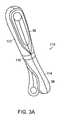
- FIG. 1Ais a schematic perspective side view of a force reflecting haptic interface in accordance with one embodiment of the invention
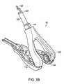
- FIG. 1Bis a schematic perspective rear view of the force reflecting haptic interface of FIG. 1A ;
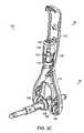
- FIG. 1Cis another schematic perspective rear view of the force reflecting haptic interface of FIG. 1A with external housing components removed;
- FIG. 2Ais a schematic perspective view of one embodiment of a user interface for a haptic interface in accordance with one embodiment of the invention
- FIG. 2Bis a schematic perspective partial sectional view of a user connection end of the user interface of FIG. 2A ;
- FIGS. 2C-2Dare schematic perspective partial sectional and exploded views of a nose end of the user interface of FIG. 2A ;
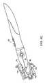
- FIG. 3Ais a schematic perspective view of a yoke arm assembly for a haptic interface in accordance with one embodiment of the invention
- FIG. 3Bis a schematic perspective view of the hinged yoke of the yoke arm assembly of FIG. 3A ;
- FIG. 3Cis a schematic perspective partial sectional view of a portion of the yoke arm assembly of FIG. 3A and the nose;
- FIG. 4Ais a partially exploded schematic perspective view of an embodiment of a docking station and user interface for use in a haptic interface in accordance with one embodiment of the invention
- FIG. 4Bis a schematic front view of the docking station of FIG. 4A ;
- FIG. 4Cis a schematic cross-sectional side view of the docking station and user interface of FIG. 4A ;
- FIG. 5is a rear schematic perspective view of an embodiment of an internal drive system for use in a haptic interface in accordance with one embodiment of the invention
- FIG. 6Ais a schematic perspective view of an embodiment of a transfer drive for powering a third articulation of a haptic interface in accordance with one embodiment of the invention
- FIG. 6Bis a schematic diagram of an automatic cable tensioning device employed to drive the third articulation of the haptic interface in accordance with one embodiment of the invention.
- FIG. 7is a schematic side view of an embodiment of an actuator assembly for use in the haptic interface in accordance with one embodiment of the invention.
- FIG. 8Ais a schematic diagram of an automatic cable tensioning device useful in a haptic interface in accordance with one embodiment of the invention.
- FIG. 8Bis a schematic side view of an actuator capstan for use in a cable drive in accordance with one embodiment of the invention.
- FIG. 8Cis a schematic plan view of an automatic cable tensioning device employed to drive a first articulation of the haptic interface in accordance with one embodiment of the invention.
- FIG. 9is a schematic plan view of an automatic cable tensioning device employed to drive a second articulation of a haptic interface in accordance with one embodiment of the invention.
- FIG. 10is a schematic plan view of an automatic cable tensioning device employed to drive a transfer drive element of a third articulation of a haptic interface in accordance with one embodiment of the invention.
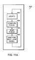
- FIGS. 11A-11Care flowcharts of an algorithm for controlling and monitoring force and internal temperature of a haptic interface in accordance with one embodiment of the invention.
- FIG. 12is a schematic diagram of an IEEE 1394 compliant interface board useful in a haptic interface in accordance with one embodiment of the invention.
- FIG. 13is a schematic perspective view of a wrist rest to be used with a haptic interface in accordance with one embodiment of the present invention.
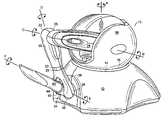
- FIG. 1Ais a schematic perspective view of a six degree of freedom force reflecting haptic interface 10 in accordance with one embodiment of the present invention.
- the interface 10includes a base 12 defining a reference ground, six joints or articulations, and six structural elements.
- a first powered tracked rotary element 14is supported by the base 12 to define a first articulation 16 with an axis of rotation “A” having a substantially vertical orientation.
- a second powered tracked rotary element 18( FIG. 5 ) is mounted on the first powered tracked rotary element 14 to define a second articulation 20 ( FIG.
- a third powered tracked rotary element 22is mounted on a generally outwardly radially disposed cantilevered extension 24 (in the form of a thigh) of the second element 18 to define a third articulation 26 having an axis of rotation “C” that is substantially parallel to the second axis, B.
- a fourth free rotary element 28is mounted on a generally outwardly radially disposed extension 30 (in the form of a shin) of the third element 22 to define a fourth articulation 32 having an axis of rotation “D” that is substantially perpendicular to the third axis, C.
- a fifth free rotary element 34 in the form of a noseis mounted on a generally outwardly radially disposed extension 36 (in the form of a yoke) of the fourth element 28 to define a fifth articulation 38 having an axis of rotation “E” that is substantially perpendicular to the fourth axis, D.
- a sixth free rotary user connection element 40 in the form of a stylus configured to be grasped by a useris mounted on a generally outwardly radially disposed extension 42 of the fifth element 34 to define a sixth articulation 44 having an axis of rotation “F” that is substantially perpendicular to the fifth axis, E.
- the nose 34When not in use, the nose 34 is secured conveniently within a docking station 46 located on the base 12 of the haptic interface 10 .
- a generally spherical upper housing 56encloses the internal components, protecting them from damage and contaminants. Interfaces employing more or less than six axes are contemplated and, in any embodiment of the haptic interface, any of the axes may be powered (i.e., controlled by a motor assembly) or free.
- FIG. 1Bis a rear schematic perspective view of the force reflecting haptic interface 10 of FIG. 1A .
- the haptic interface 10has at least two connection ports formed in the housing 12 .
- the electrical connectionsemploy a ferrite bead 54 to offer RF shielding, parasitic suppression, and RF decoupling.
- a power connection 50supplies electrical power to the interface 10 to operate internal components, including control circuitry, sensors, actuators and display elements.
- the interface 10also includes at least two Institute of Electrical and Electronics Engineers (IEEE) 1394 port connections 52 a , 52 b , such as the FIREWIRE® brand sold by Apple Computer, Inc.
- IEEEInstitute of Electrical and Electronics Engineers
- the interface 10has both a PHY interface connection (which manages physical interface, CRC checking, pass-through operations, and speed negotiations) and a LINK controller connection (which formats data, and manages isochronous transfers), creating a two-channel interface.
- IEEE 1394 connectionsprovide many advantages over prior peripheral connection methods. For example, a IEEE 1394 connection transfers data much faster than conventional parallel or serial connections, or even higher speed Universal Serial Bus (USB) connections.
- the dual-connection embodiment depicted in FIG. 1Benables the haptic interface 10 to operate at 100, 200, and 400 Mbs bus speeds, which is useful for high levels of data transfer in real-time. Such speeds are possible because the connections provide dedicated time slots for data transfer regardless of other operations.
- the IEEE 1394 connectionautomatically recognizes the presence of the peripheral device, without the need for additional installation software.
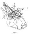
- FIG. 1Cdepicts a rear schematic perspective view of the haptic interface 10 with the exterior housings removed.
- Base 12is sized to accommodate control circuitry, such as a pair of computer boards, 58 a , 58 b , in this embodiment arranged substantially vertically within the base 12 and substantially parallel to each other.
- power board 58 agenerally controls the power to the haptic interface 10
- the IEEE 1394 interface board 58 bcontrols complex force feedback, sensing, and other functions.
- Also contained in the baseis the motor assembly 401 for the first powered tracked rotary element 14 , and a number of steel plates 59 for ballast, to at least partially offset forces arising during use of the haptic interface 10 . Rubberized or suction cup feet disposed on an underside of the interface 10 help stabilize the interface 10 and prevent it from sliding on smooth surfaces. At least one stop within the base 12 prevents over-rotation of rotary element 14 .
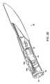
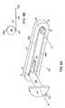
- FIG. 2Adepicts a user interface 60 of the haptic interface 10 .
- the user interface 60consists of a nose end 34 and a user connection section, such as a stylus 40 .
- the housing of both the nose 34 and stylus 40are of split construction, for both ease of assembly and component construction, although a single housing component for either the nose 34 and/or stylus 40 is contemplated.
- two pieces of the stylus housing 62are removable.
- the entire housing 62 of the stylus 40may be split, allowing for its complete removal.
- the housing 62is made in four main pieces to allow for faster assembly.
- the removable parts of the housing 62may be secured with a compression ring 64 , may snap together, or use other means of joining.
- the rear portion of the stylus 40is ergonomically designed and slips on the end of a connector shaft 90 ( FIG. 2C ) as a sleeve.
- Two user inputs 66 a , 66 bare depicted in this embodiment as buttons, but switches, toggles, rollers, or other devices may be used.
- First input 66 a and second input 66 ballow the user to control various functions of the stylus 40 and interface 10 .
- the first input 66 aoperates as a standard ON/OFF toggle for the force feedback function of the interface 10
- the second input 66 bincorporates other system features, although either, both, or neither of the inputs 66 a , 66 b may be customizable by the user.
- pressing the second input 66 ballows the user interface 60 and interface 10 to operate in a manner similar to that of a computer mouse without force feedback.
- second input 66 bincludes, but are not limited to, a PAUSE or SLEEP control, force feedback toggle, digitizer control, spatial position reset, or any other option as desired by the user or required for a particular application.
- either buttonmay be used to toggle the haptic interface between two different functions.
- the nose housing 68 and stylus housing 62meet at or near the compression ring 64 .
- the nose housing 68is separable into two pieces. Once assembled, the nose housing 68 forms at least two projections 70 that engage bearings 120 of a mating yoke 36 . At or near the end of at least one of these projections 70 is a potentiometer blade 72 , which drives a potentiometer 130 located within the yoke 36 ( FIG. 3B ).
- the outside surface of the nose housing 68can incorporate at least one recess 74 to engage a spring-loaded projection 154 ( FIG. 4A ) within the docking station 46 on the base 12 of the haptic interface 10 .
- the recess 74may be oval, triangular, arcuate, or any other shape that allows for proper engagement with the spring-loaded projection 154 .
- a shaped tip 76protrudes from or near the tapered end of the nose 34 .
- the tip 76may be used for precise tracing of the contours of a physical model or drawing and recording the accompanying data in computer memory, when the haptic interface 10 is used as a digitizer using the inputs 66 a , 66 b .
- the tapered end of a plastic housing 68may itself be used for this purpose, a hardened metal tip can be used, as it will more effectively withstand wear.
- the shaped tip 76when functioning as a digitizer, may employ a manual or spring-loaded switch, optical technology, or any other technology known in the art.
- a snap-type connection 80serves as a connection element for the two halves for the user interface 60 .
- a four-jaw snap barrel chuck with an O-ring 82is used, but any snap-type connection that can properly join with a connector 96 on a connector shaft 90 of the nose 34 may be employed.
- the O-ring 82keeps the jaws in a collapsed mode, thus allowing a connector to be trapped therein.
- the snap-type connection 80 used in the stylus 40serves at least several purposes. First, the snap-type connection 80 allows for simple changeover of a variety of user connection elements for various applications.
- the stylus 40instead of the stylus 40 shown in the figures, pistol-grip, ball, mouse, joystick, steering wheel, or other connections may be employed. Such an arrangement also allows for easy repair or replacement of the user interface 60 , should it become damaged. Second, the release characteristics of the snap-type connection 80 prevent damage to the haptic interface 10 if the stylus 40 is aggressively pulled. Generally, the maximum range of force typically applied to the stylus 40 during use is approximately three-quarters to one pound. A breakaway force of about five times the usage force will prevent damage to the haptic interface 10 . Moreover, employing a snap-type connection 80 allows the user interface 60 to maintain structural integrity without the need for additional screws or other fasteners.
- a groove 84is located and sized to mate with a guide 98 of the connector shaft 90 ( FIG. 2C ).
- the groove 84can either be formed within a portion of the housing 62 , or may be formed by a gap where the two removable portions of the housing 62 join.
- FIGS. 2C and 2Dthe nose 34 of the interface 60 is shown with a portion of the housing 68 removed. Moreover, FIG. 2D depicts a partially exploded nose 34 of the user interface 60 .
- bearing seats or rests 86provide a location for at least one set of bearings 88 .
- use of a plurality of bearings 88 to support the connector shaft 90eliminates undesirable play in the user interface 60 .
- a first stop 92 located within the housing 68engages a second stop 94 on the connector shaft 90 to prevent over-rotation of the connector shaft 90 .
- the first stop 92also prevents the bearings 88 from moving axially within the nose 34 , which could result in damage to the connector shaft 90 and nose 34 .
- the connector shaft 90Contained partially within the nose housing 68 is the connector shaft 90 .
- the distal end of the shaft 90is a conical connector 96 that serves as the joining element between the nose 34 and stylus 40 .
- a conical connector similar to an audio device jackis employed, but diamond, tapered cylinder, and other non-conical shapes also may be used, provided they mechanically interlock with the snap-type connection 80 in the stylus 40 .
- a guide 98extends radially outward from the connector shaft 90 and is sized to mate with the groove 84 on the stylus 40 .
- the connector shaft 90is supported by at least one set of bearings 88 , which allows for low-friction rotation of the shaft 90 within the housing 68 .
- a potentiometer retainer 100also prevents non-rotational motion of the shaft 90 , by securing the bearings 88 , as well as a potentiometer 104 .
- potentiometersare of the type that employ a floating central disk, similar to those of the 251 Series, manufactured by CTS Corp., are used in the haptic interface 10 , although other sensors for outputting a signal representative of position may be employed.
- a potentiometer blade 102joins the connector shaft 90 at or near its terminus.
- a plurality of wiresexit the potentiometer 104 and are routed via the interior portions of the nose 34 , yoke 36 , shin 30 , and thigh 24 to the computer boards within the base 12 of the haptic interface 10 .
- the digitizing tip 76is secured within the tapered end of the housing 68 .
- the rotational forceis directed via the groove 84 to the guide 98 .
- the guide 98is a part of the connector shaft 90
- the shaftrotates about the F axis.
- This movement of the connector shaft 90rotates the potentiometer blade 102 , which in turn drives the potentiometer 104 .
- Electronic output signalsare then directed through the wiring back to the computer boards of the haptic interface 10 .
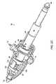
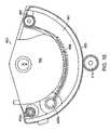
- FIG. 3Adepicts a yoke arm assembly 110 of the haptic interface 10 .
- the yoke arm 110consists of two main parts, the shin 30 and the yoke 36 .
- the shin 30 and yoke 36are joined at or near the midpoint of the yoke arm 110 .
- a shin band 116integral to housing 114 , contains a stop (not shown) which engages stop 124 ( FIG. 3B ).
- both the shin 30 and yoke 36are of split construction, for ease of assembly and component construction.
- the split designallows for the component parts to be designed so they positively clamp the bearings 120 with pressure at all times, such that there is no play or sloppiness during use. By ensuring essentially zero backlash, very high system resolution and responsiveness can be achieved.
- FIG. 3Bdepicts the yoke 36 of the yoke arm assembly 110 .
- the branches of the yoke 36are joined by two hinge pins 118 that allow for easy assembly of the housing 114 and eliminate the need for screws or other fasteners.
- a molded flexible jointmay be used in lieu of hinge pins 118 .
- the use of the split housing 114also allows the bearings 120 to be clamped with positive pressure at all times to eliminate play and backlash in the device.
- Use of a yoke 36 in this embodiment instead of a cantilever connectioneliminates looseness and play in the device, which would be otherwise felt by the user, without the need for other mechanical reinforcements.
- Each branch of the yoke 36contains at least one bearing 120 that joins one of the projections 70 on the nose 34 .
- the bearings 120provide low-friction rotational movement of the projections 70 within each branch of the yoke 36 .
- the yoke 36joins the yoke shaft 122 at a point at or near the shin band 116 . Extending radially outward from the yoke shaft 122 is a first stop 124 , designed to prevent over-rotation of the yoke shaft 122 by contacting a corresponding second stop on the inside circumference of the shin band 116 .
- the terminus of the yoke shaft 122joins a blade 126 which drives a potentiometer 136 contained within the shin 30 of the yoke arm assembly 110 .
- a groove 123is sized to receive a retaining ring to prevent the axial movement of the yoke shaft 122 .
- the yoke arm assembly 110is shown with portions of the housings 114 , 112 of both the shin 30 and yoke 36 removed. At least one branch of the yoke 36 also contains a potentiometer retainer 128 and a potentiometer 130 , which are arranged such that the retainer 128 is between the bearing 120 and the potentiometer 130 . A plurality of wires (not shown) exit the potentiometer 130 and are routed via the interior portions of the yoke 36 , shin 30 , and thigh 24 , to the computer boards within the base 12 of the haptic interface 10 .
- the yoke shaft 122extends from the yoke 36 into the shin 30 , and rotates about the D axis within the housing 112 , supported by at least one set of bearings 132 .
- use of a plurality of positively clamped bearings 120 to support the yoke shaft 122eliminates undesirable play in the yoke arm assembly 110 .
- a retention ring 133prevents axial movement of the yoke shaft 122 .
- a potentiometer retainer 134prevents non-rotational motion of the yoke shaft 122 by securing the bearings 132 and also prevents movement of the potentiometer 136 .
- a plurality of wiresexit the potentiometer 136 and are routed via the interior portions of the yoke 36 , shin 30 , and thigh 24 , to the main computer board within the base 12 of the haptic interface 10 .
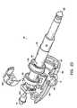
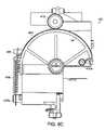
- FIG. 4Adepicts a partially exploded docking station 46 used in the haptic interface 10 .
- the docking station 46is secured within the base 12 of the haptic interface 10 , and serves as a resting point and home position for the nose 34 of the interface 60 .
- a tapered barrel 150 of the docking station 46is configured to receive the nose 34 .
- a spring loaded projection 154 within the barrel 150mates with the recess 74 on the nose 34 , thereby retaining the interface 60 within the docking station 46 .
- other types of retaining mechanismssuch as magnets or compression rings may be employed.
- other embodiments of the present inventionmay incorporate a male docking station 46 with a female connection on the nose 34 of the user interface 60 .
- FIGS. 4B and 4Ca schematic view directed down the barrel 150 of the docking station 46 and a cross-sectional side schematic view of the docking station 46 are depicted, respectively.
- elements disposed within the tapered barrel 150 of the docking station 46can serve other functions of the haptic interface 10 .
- a switch 152is located on the inner circumference of the barrel 150 and detects the presence of the nose 34 and recalibrates the position of the interface 10 to home. Thus, a user may reset the spatial position of the entire interface 10 to a zero position or a user-defined home position, as required.
- an LED 156is located at the base of the tapered barrel 150 .
- the LED 156may signal a variety of diagnostic functions and/or errors by emitting various colors of different characteristics. For example, the LED 156 may blink to remind the user to dock the nose 34 at the completion of a program.
- a red strobe emissionmay be used to indicate a diagnostic problem with the haptic interface 10 or stylus 40 .
- a steady green lightfor example, may indicate that the haptic interface 10 is functioning properly.
- the LED 156is a blue neon pipe.
- the barrel 150itself may be constructed of a clear plastic material. By energizing LEDs 156 installed proximate this clear barrel 150 , the entire barrel 150 would emit light, which could be more visible to a user and be more visually appealing.
- FIG. 5depicts a rear schematic perspective view of the internal drive system of one embodiment of the haptic interface 10 .
- the base 12supports the first powered tracked rotary element 14 to define a first articulation 16 about the axis A having a substantially vertical orientation.
- a vertically oriented first actuator 401( FIG. 1C ) drives a vertically oriented first threaded capstan 413 that in turn manipulates a first cable 453 ( FIG. 8C ).
- the first cableis secured at, at least two points 455 a , 455 b ( FIG. 8C ), to the horizontally oriented first powered tracked rotary element 14 , and thus rotates the first element 14 about the A axis.
- first motor assembly 401mounted on the first powered tracked rotary element 14 are a second powered tracked rotary element 18 and a rotary transfer drive element 164 of the third powered tracked rotary element 22 and their associated motor assemblies 501 , 601 .
- Both the second powered tracked rotary element 18 and the rotary transfer drive element 164operate in a manner similar to that of the first powered tracked rotary element 14 .
- FIGS. 7 and 9 and accompanying textFor a more detailed description of the second motor assembly 501 and its operation, refer to FIGS. 7 and 9 and accompanying text.
- FIGS. 7 and 10provide a more detailed description of the third motor assembly 601 and its operation.
- the orientations of the second powered tracked rotary element 18 and rotary transfer drive element 164 and their associated motor assemblies 501 , 601allow for a very compact configuration and a reduction in overall size of the haptic interface 10 .
- the second motor assembly 501 and third motor assembly 601are installed horizontally, substantially parallel to each other, in a balanced configuration about the A axis. This arrangement imparts rotational forces about the B axis on either side of the geometric center A, thus relatively evenly loading the interface 10 on both sides.
- the torque from one rotary elementis transferred through a central shaft upon which the other element rests.
- the second rotary element 18 and rotary transfer drive element 164are installed on opposite ends of the first rotary element 14 .
- This particular arrangementeliminates the requirement for a large housing to enclose the internal components and simplifies access for repair.
- the balanced arrangementalso more evenly distributes the overall inertia of the motors within the device, thus improving stability of the haptic interface 10 as opposed to a cantilevered arrangement.
- a single assembly shaft 172installed substantially horizontal and parallel to the second and third motor assemblies 501 , 601 , and in line with the B axis, secures the second rotary element 18 and rotary transfer drive element 164 , allowing for easy assembly.
- an assembly rod 173runs through shaft 172 and secures the spherical housing 56 to the interface 10 ; thus the need for a number of screws or other fasteners penetrating the housing 56 is eliminated.
- the particular embodiment of the haptic interface 10 shown in FIG. 5also utilizes at least one torsion spring 160 on the B axis of the interface 10 .
- the weight of the thigh 24 , shin 30 , yoke 36 , nose 34 , and stylus 40tend to oppose many of the manipulations of the user.
- the weight of those elementsinduces rotation about the B axis.
- Such rotationsare felt by the user as a sluggishness or resistance when using the haptic interface 10 .
- previous haptic interfacesutilized bulky counterweights attached to the rotary elements.
- the haptic interface 10 of the present inventionutilizes solely the torsion spring 160 , to offset the forces imposed on rotary element 18 without the need for any counterweight.
- FIG. 6Adepicts an embodiment of the transfer drive 162 useful in the haptic interface 10 .
- the rotary transfer drive element 164rotates about the B axis, the rotary transfer drive element 164 defines a third articulation 26 having an axis C, located on the outwardly radially disposed extension 24 of the second element 18 .
- the element 164rotates a transfer drive shaft 166 aligned with the second axis B, converting rotary motion to linear motion of first 168 a and second 168 b transfer drive rods disposed along the radial extension 24 of the second element 18 .
- the first 168 a and second 168 b drive rodsterminate in looped braided steel cable ends which are hooked onto a raised ground tab 165 of the third rotary element 22 .
- the second transfer drive rod 168 bis directly grounded through looped cable ends to each of the transfer drive shaft 166 and the third rotary element 22 ; whereas, the first drive rod 168 a is directly grounded through a looped cable end to a raised ground tab 167 of the third rotary element 22 and indirectly grounded with a single cable to the transfer drive shaft through a clutch post 757 ( FIG. 6B ) and spring 759 .
- the drive rods 168 a , 168 bminimize cable lengths and therefore enhance the stiffness and rigidity of the transfer drive 162 .
- the cablesare used solely at the grounding points, with one cable 753 end of the first drive rod 168 a being routed through the automatic cable tensioning device 751 depicted in FIG. 8A to substantially eliminate backlash in the third axis drive.
- FIG. 6Bone embodiment of a cable tensioning device 351 described later with respect to FIG. 8A is employed in the transfer drive 162 of the haptic interface 10 , defined generally here as cable tensioning device 751 .
- the cable 753(from the terminus of the first drive rod 168 a ) is fixed to shaft 166 at a first ground location 755 a and circumscribes the shaft 166 in a clockwise direction.
- the cable 753wraps around a clutch post 757 , and thereafter, is attached to a spring 759 in tension, which is grounded to a radial extension 170 of shaft 166 at ground 755 b .
- Tabs, slots, and other guide featuresmay be provided in the shaft 166 to facilitate routing and retention of the cable 753 in the proper location and orientation throughout the range of motion of the shaft 166 .
- the tension achieved with the automatic cable tensioning device 751also provides added stiffness and rigidity in the drive system.
- FIG. 7shows a schematic representation of a typical actuator assembly 301 used in one embodiment the haptic interface 10 .
- each actuator 303is fitted with an encoder board 305 at the base of the actuator 303 .
- An emitter/detector optical encoder chip 307is secured on or within the board 305 .
- Rotation of the actuator shaft 311 ais tracked by mounting a reflective encoder disk 309 on an actuator shaft extension 311 b extending from the actuator 303 remote from the capstan 313 .
- the overall volume of the actuator assembly 301is reduced, since a non-reflective disk requires the use of an emitter/detector pair that straddles an edge of the disk 309 .
- the emitter/detector 307is a single unit mounted at the end of the actuator 303 , directing pulses to, and receiving pulses from, the reflective encoder disk 309 .
- the actuator 303causes the disk 309 to rotate, or as the disk 309 rotates due to user movement of the manipulation device 10
- the emitter/detector 307outputs pulses that are in turn reflected by the disk 309 , allowing the angular orientation of the articulation to be determined.
- Three of these actuator assemblies 301are used in the haptic interface 10 , one for each of the powered articulations 16 , 20 , 26 ; however, more or less actuator assemblies may be employed depending on the number of powered axes.
- the actuator assembly 301uses components readily available in the market.
- the actuator 303is a D.C. motor.
- a reflective encoder disk similar to the 8000 Series manufactured by Agilent Technologiesis utilized.
- the capstan 313 and reflective encoder disk 309may be secured to the actuator shaft 311 a and extension 311 b by a variety of means, such as mechanical connections or press fit connections employing heat expansion and cooling.
- the capstan 313 and disk 309are secured using a strong bonding adhesive, such as one marketed under the name Loctite®, manufactured by Henkel Consumer Adhesives, Inc., to reduce the overall size of the assembly 301 .
- the interface 10employs three dedicated actuators (described above) fitted with capstans and corresponding cables to power rotary axes A-C.
- Cable drivesprovide good force transmission characteristics with low weight; however, backlash can be a problem, especially in high precision, high resolution haptic interfaces. Backlash or play in a rotary mechanical transmission, such as those employed in the interface 10 , is most evident when direction of rotation is reversed.
- One method of reducing backlashis to provide a manual adjustment feature to adjust the position of one or both of the cable ends relative to ground so that slack in the cable can be reduced.
- the cablecan be preloaded in tension so that there is minimal slippage between the cable and the actuator capstan as the capstan rotates; however, as the cable stretches and the components of the mechanism wear over time, cable tension is reduced and must be periodically adjusted to prevent slippage. Additionally, cable tension is difficult to measure and excessive tensioning can lead to deformation of the structural elements and accelerated, premature wear in the articulation bearings.
- FIG. 8Ais a schematic diagram of an automatic cable tensioning device 351 that overcomes many of the limitations of known cable drives and is useful in the powered axes of the haptic interface 10 .
- the tensioning device 351automatically loads the cable 353 to a predetermined tension and maintains that level of tension over time, even in the event of cable stretching and component wear.
- the tensioning device 351includes a cable 353 fixed at proximal and distal ends directly or indirectly to a ground surface, shown generally at 355 a , 355 b .
- a non-rotating clutch post 357also fixed to ground, is located along the cable path.
- a spring 359is disposed along the cable path between the clutch post 357 and ground 355 b .
- the actuator capstan 313is provided along the cable path between the clutch post 357 and ground 355 a on the side opposite the spring 359 .
- the cable 353extends from ground 355 a , circumscribes both the actuator capstan 313 and the clutch post 357 at least once each, and is connected to the spring 359 that is in tension and connected to ground 355 b.
- a non-rotating postsuch as the clutch post 357
- the amplification factoris a function of post diameter, wrap angle of the cable around the post, and the coefficient of friction between the cable and the post. Accordingly, for a given spring tension, as wrap angle and/or friction increases, a larger downstream cable force can be offset or resisted.
- the tensioning device 351automatically self-adjusts and maintains cable tension at a predetermined magnitude, taking up any slack when the capstan 313 rotates in a first direction and locking when the capstan 313 rotates in a second direction.
- an enlarged view of an actuator capstan 313 for use in one embodiment of the haptic interface 10is shown. While the capstan 313 may be a uniform cylinder, in one embodiment, the capstan 313 includes a helical channel 315 formed along an exterior surface thereof.
- the helical channel 315may include a generous radius without sharp edges, which could cut through the cable 353 or otherwise reduce cable life.
- the helical channel 315nests and routes the cable 353 , preventing overlapping or tangling of the cable 353 on the capstan 313 .
- a nylon coated cable 353is used to prevent slippage upon the capstan 313 and to protect the cable 353 from damage to ensure a long life.
- a variety of cable materialscan be used including, but not limited to, tungsten, stainless steel, uncoated steel, or another form of coated steel. Also, the number of wraps the cable makes around the capstan is dependant on capstan and cable size, anticipated loads, and other related considerations.
- the cable tensioning device 351 described aboveis employed in the first articulation 16 of the haptic interface 10 , defined generally here as cable tensioning device 451 .
- Depictedis a generally D-shaped hub portion of the first element 14 .
- a cable 453is fixed to the first powered tracked rotary element 14 at a first ground location 455 a and circumscribes the element 14 in a counterclockwise direction.
- the cable 453wraps an actuator capstan 413 disposed substantially tangentially to the circumference of the element 14 before wrapping several times around a clutch post 457 . Thereafter, the cable 453 is attached to a spring 459 in tension, which is grounded, to the element 14 at ground 455 b .
- the actuatorSince the actuator is fixed in the housing 12 of the interface 10 , as the actuator rotates the capstan 413 , the first element 14 is caused to rotate about first axis A. Tabs, slots, and other guide features may be provided in the element 14 to facilitate routing and retention of the cable 453 in the proper location and orientation throughout the range of motion of the element 14 .
- the hub portion of the first rotary element 14is generally D-shaped.
- a circular or partially circular element 14is contemplated.
- the rotary element 14is supported at a centrally located axis shaft on the A axis.
- the first rotary element 14may be either of a segmented construction, as shown, or solid, perforated, or any other construction, as required. If required, a support surface for the other rotary elements and their associated motors may be secured to the first rotary element 14 .
- the A axis shaftmay be hollow or include a groove to accommodate any of the control or power wiring of the haptic interface 10 . Alternatively, openings may be formed within first rotary element 14 for this purpose.
- the cable tensioning device 351 described aboveis employed in the second articulation 20 of the haptic interface 10 , defined generally here as cable tensioning device 551 .
- Depictedis a generally D-shaped hub portion of the second element 18 .
- a cable 553is fixed to the element 18 at a first ground location 555 a and circumscribes the element 18 in a counterclockwise direction.
- the cable 553wraps an actuator capstan 513 disposed substantially tangentially to the circumference of the element 18 before wrapping several times around a clutch post 557 .
- the cable 553is routed through a recess 561 in the rotary element 18 and attached to a spring 559 in tension, which is grounded to the element 18 at ground 555 b .
- tabs, slots, and other guide featuresmay be provided in the outer circumference of element 18 to facilitate routing and retention of the cable 553 in the proper location and orientation throughout the range of motion of the element 18 .
- the second rotary element 18is penetrated by at least two control wire conduits 563 a , 563 b .
- These conduits 563 a , 563 bprovide a location for the power and control wiring and generally restrict the wires movement as the element 18 rotates.
- the rotary element 18rotates about a centrally located B axis shaft that may be smooth, include grooves or tabs, or be threaded as required.
- a circular rotary elementmay be employed. Use of a D-shaped element 18 , however, can reduce the overall size of the haptic interface 10 .
- the cable tensioning device 351 described aboveis employed in the third articulation 26 of one embodiment of the haptic interface 10 , defined generally here as cable tensioning device 651 .
- Depictedis a generally D-shaped hub portion of the rotary transfer drive element 164 .
- a cable 653is fixed to the element 164 at a first ground location 655 a and circumscribes the element 164 in a counterclockwise direction.
- the cable 653wraps an actuator capstan 613 disposed substantially tangentially to the circumference of the element 164 before wrapping several times around a clutch post 657 .
- the cable 653is routed through a recess 661 in the rotary transfer drive element 164 and attached to a spring 659 in tension which is grounded to the element 164 at ground 655 b .
- tabs, slots, and other guide featuresmay be provided in the outer circumference of rotary transfer drive element 164 to facilitate routing and retention of the cable 653 in the proper location and orientation throughout the range of motion of the element 164 .
- the rotary transfer drive element 164rotates freely about axis B. Rotational force is transferred to third articulation 26 by transfer drive shaft 166 and associated components depicted in more detail in FIGS. 6A-6B and described in the accompanying text.
- a circular rotary elementmay be employed as an alternative to the D-shaped element shown in the FIG. 10 . Use of a D-shaped element 164 , however, can reduce the overall size of the haptic interface 10 .
- the three powered tracked rotary elements 14 , 18 , and 22may be either “powered” or “free.”
- the actuatorsWhen powered, the actuators are energized and can control the rotation of the respective rotary elements, directing the elements to either resist or force the movements of the interface user depending on the application.
- This powered settingis useful for force feedback situations, such as simulating surgical techniques, providing feedback during computer game play, etc.
- the free settingthe actuators are not energized and the rotary elements are subject to the forces of the interface user.
- Such a settingis useful for digitizing drawings or objects directly into a computer program, using the user interface as a personal computer mouse, drafting computer-aided design (CAD) images, etc.
- Any number of the three rotary elementsmay be in either powered or free mode for any particular application, or may switch between the two modes when certain criteria are met.
- the moveable portions of the haptic interfaceLight weight, low cost, high stiffness, and high strength are preferred characteristics for the moveable portions of the haptic interface. For these reasons, injection molded 40% carbon fiber filled nylon or similar compositions may be selected for the structural elements such as second element 18 , second element extension 24 , third element 22 , third element extension 30 , fifth element 34 , and sixth element 40 . Other glass and carbon fiber filled, injection molded plastics may be used as well.
- the external gripping surfaces of the stylus housing 62are treated with an anti-slip coating or paint to prevent the stylus 40 from slipping from the user's grasp. Alternatively, the external surfaces may be physically textured or knurled as required.
- the haptic interface 10may be used in conjunction with a wrist rest 700 as depicted in FIG. 13 .
- a wrist rest 700is disclosed in U.S. Pat. No. 6,417,638. All internal components may be manufactured from plastics, metal, or any combination of such materials. Desirable characteristics for the base 12 and spherical housing 56 of the haptic interface 10 also include low cost, high strength, and high stiffness; however, because the base structure may also serve as a heat sink for the internal electronics, it is desirable that the base structure be thermally conductive.
- FIG. 11Adepicts an algorithm 800 employed in one embodiment of the interface controller for measuring and controlling the forces generated by the haptic interface 10 .
- Signals from the actuators and/or potentiometersfirst update 802 the force reading stored in memory.
- a new forceis computed 804 , and the electrical current corresponding to that computed force is sent 806 to one of the actuators, to either rotate the associated element or resist such a rotation.
- the algorithm 800then awaits a responsive signal 808 from the actuators and/or potentiometers (due to user manipulation) and updates the stored force reading 802 accordingly.
- This algorithmcontinues to operate during an entire program, translating and tracking electrical signals to allow the interface user to interact with a computer application program.
- Temperature sensing devicesare required in consumer products to prevent overheating and possible injury to users and to prevent damage to a device's internal components.
- thermocouplesare used to measure temperatures of internal motors and other components to meet this requirement.
- One embodiment of the haptic interface 10 in accordance with the present inventionuses a computer algorithm to monitor temperature within the device, in the absence of any thermocouple or other sensor that directly reads internal temperature.
- a flowchart of such an temperature calculating algorithm 810(a subroutine of control algorithm 800 described above) is depicted in FIG. 11B .
- the algorithm 810use time and actuator current usage to estimate temperature.
- the algorithm 810As electrical current is sent to an actuator to generate a force 806 upon a rotary element (to either rotate the element or resist such a rotation), the algorithm 810 measures the current delivered to the motor and the total length of delivery time. The algorithm 810 then computes the estimated internal actuator temperature based on the amount of time the current has been delivered to the actuator, thereby updating its thermal model 812 .
- the forceis applied to the rotary element 816 . If, however, the internal temperature exceeds about 80° C. 818 , the force is disabled 820 , and delivery of current to the actuator is terminated. Under the latter condition, the temperature data is cached 822 for application in a temperature error algorithm 830 (described below), and a temperature error message 824 is delivered to the user.
- This errormay take the form of a notation within the associated computer program to be displayed on a computer screen and/or will result in a visible change in the LED in the haptic interface docking station to indicate a system error.
- the temperature limitcan be adjusted, as required, for any given application or to prevent damage to internal device components.
- a threshold temperature of 49° C.for example, can be set to cause shutdown of the interface 10 before any damage occurs to the actuators or other internal components.
- a flowchart for the temperature error algorithm 830is depicted in FIG. 11C .
- the subroutine temperature error algorithm 830determines the consequences of a possible temperature error. A determination that no temperature error has occurred 832 causes a bypass of steps 834 and 836 . If however, the temperature calculating algorithm 810 determines that an error has occurred 824 , the temperature error algorithm 830 reads the cached temperature data 834 , stored in the cache temperature 822 step of the temperature calculating algorithm 810 . The algorithm 830 then computes any thermal decay 836 of interface components due to the excessive temperature. Information regarding decay, and how it will affect future interface performance, is stored 838 and taken into account in any later kinematics calculations 840 . Thus, as interface performance is impacted by temperature errors, the interface 10 can compensate, as required, to continue to deliver an accurate force-reproduction experience for the user.
- FIG. 12a schematic representation of the IEEE 1394 compliant interface board 58 b of one embodiment of the haptic interface 10 is depicted.
- the board 58 bcontrols various types of electromechanical interface 900 and digital 902 functions.
- the board 58 bis powered by the haptic interface power supply 906 .
- the electromechanical interface functions 900 of the board 58 bultimately control the function of the various components 904 (described in more detail above) of the haptic interface 10 .
- current drivers 910control the function of the three actuators.
- the current drivers 904consist of three channels, for permanent magnet D.C. servomotors.
- the drivers 904operate at a maximum continuous output of 14.4 Watts per channel, plus or minus 18 volts mA. The maximum output for the three channels is 25 Watts.
- the drivers 904also have 12 bits of resolution at 1 kHz bandwidth.
- Encoder counters 912consist of three channels. The counters 912 can receive a rate of pulses up to 500 kHz and 16 bits of resolution.
- the analog potentiometer inputs 914also have three channels, and typically recognize 0-5 volt signals from 5K Ohm potentiometers. The inputs also have 10 bits of resolution and 1 kHz of filtering with a 3-dB cutoff.
- Digital input/output 916consists of four output channels and eight input channels. The digital input/output operates with debounced TTL in and TTL out with sufficient current to drive any LEDs.
- the digital functions 902 of the board 58 bcommunicate with the various electromechanical interface functions 900 and the program host computer 908 via the IEEE 1394 connection 926 .
- Local feedback and safety logic function 918performs several functions. These include, but are not limited to, velocity based positive feedback to compensate for back-emf of motor and friction, velocity threshold shutdown, current shutdown if threshold exceeded, and watchdog shutdown if not updated within a certain time.
- a 32-bit read-only serial number interface 920identifies the haptic interface 10 to the host computer.
- the digital functions 902also include 32 bit read-write volatile 922 and non-volatile 924 registers.
- the electronics of the interfacemay include an 8031 microprocessor, FLASH memory, Programmable Logic Device (PLD) and PLD-based delta sigma A/D converters, and a four-layer printed circuit card.
- PLDProgrammable Logic Device
- the microprocessornegotiates with the host computer, manages system initialization and isochronous data transfers during operation, loads the PLD configuration, and manages the FLASH memory read/write operations (to allow remote updates of the 8031 program, the PLD configuration, and system constants).
- the PLDimplements three 16-bit quadrature encoder interfaces, encoder speed detection, power fail and over current safety logic, motor enablement monitoring, 512 byte stack RAM bank to supplement 8031 memory, FIFO interface to IEEE 1394 connection link controller isochronous data mover port, control for three nine-bit accurate delta-sigma potentiometer A/D converters, three ten-bit PWM generators to set motor currents, triangle wave frequency generator, and power supply sync frequency generator.
- the power board 58 a( FIG. 1C ) includes a power supply, safety circuitry, three PWN amplifiers, PWM-based D/A converters, and a two-layer printed circuit card.
Landscapes
- Engineering & Computer Science (AREA)
- General Engineering & Computer Science (AREA)
- Theoretical Computer Science (AREA)
- Human Computer Interaction (AREA)
- Physics & Mathematics (AREA)
- General Physics & Mathematics (AREA)
- User Interface Of Digital Computer (AREA)
- Position Input By Displaying (AREA)
Abstract
Description
Claims (35)
Priority Applications (6)
| Application Number | Priority Date | Filing Date | Title |
|---|---|---|---|
| US10/697,963US7411576B2 (en) | 2003-10-30 | 2003-10-30 | Force reflecting haptic interface |
| PCT/US2004/036147WO2005043365A2 (en) | 2003-10-30 | 2004-10-29 | Force reflecting haptic interface |
| CNB2004800354458ACN100444085C (en) | 2003-10-30 | 2004-10-29 | Force Feedback Haptic Interface |
| JP2006538362AJP4866735B2 (en) | 2003-10-30 | 2004-10-29 | Reaction force presentation type haptic interface |
| US12/169,304US8994643B2 (en) | 2003-10-30 | 2008-07-08 | Force reflecting haptic interface |
| JP2010270956AJP2011044185A (en) | 2003-10-30 | 2010-12-03 | Force reflecting haptic interface |
Applications Claiming Priority (1)
| Application Number | Priority Date | Filing Date | Title |
|---|---|---|---|
| US10/697,963US7411576B2 (en) | 2003-10-30 | 2003-10-30 | Force reflecting haptic interface |
Related Child Applications (1)
| Application Number | Title | Priority Date | Filing Date |
|---|---|---|---|
| US12/169,304DivisionUS8994643B2 (en) | 2003-10-30 | 2008-07-08 | Force reflecting haptic interface |
Publications (2)
| Publication Number | Publication Date |
|---|---|
| US20050093821A1 US20050093821A1 (en) | 2005-05-05 |
| US7411576B2true US7411576B2 (en) | 2008-08-12 |
Family
ID=34550503
Family Applications (2)
| Application Number | Title | Priority Date | Filing Date |
|---|---|---|---|
| US10/697,963Expired - LifetimeUS7411576B2 (en) | 2003-10-30 | 2003-10-30 | Force reflecting haptic interface |
| US12/169,304Active2026-03-26US8994643B2 (en) | 2003-10-30 | 2008-07-08 | Force reflecting haptic interface |
Family Applications After (1)
| Application Number | Title | Priority Date | Filing Date |
|---|---|---|---|
| US12/169,304Active2026-03-26US8994643B2 (en) | 2003-10-30 | 2008-07-08 | Force reflecting haptic interface |
Country Status (4)
| Country | Link |
|---|---|
| US (2) | US7411576B2 (en) |
| JP (2) | JP4866735B2 (en) |
| CN (1) | CN100444085C (en) |
| WO (1) | WO2005043365A2 (en) |
Cited By (23)
| Publication number | Priority date | Publication date | Assignee | Title |
|---|---|---|---|---|
| US20070120512A1 (en)* | 2005-11-16 | 2007-05-31 | Alin Albu-Schaffer | Method for controlling a robot arm, and robot for implementing the method |
| US20090143197A1 (en)* | 2007-11-30 | 2009-06-04 | Cycling & Health Tech Industry R & D Center | Dual-shaft hinge module for interactive training apparatus |
| US20090241705A1 (en)* | 2008-03-28 | 2009-10-01 | Johnson Electric S.A. | Telescopic tilting device |
| US20100010670A1 (en)* | 2007-04-03 | 2010-01-14 | Kabushiki Kaisha Yaskawa Denki | Robot |
| US20110232399A1 (en)* | 2010-03-24 | 2011-09-29 | Hong Fu Jin Precision Industry (Shenzhen) Co., Ltd. | Deceleration mechanism |
| KR101283327B1 (en)* | 2011-04-14 | 2013-07-17 | 에이알비전 (주) | Haptic of haptic device for simulator of intravenous injection |
| EP2743801A2 (en) | 2012-12-13 | 2014-06-18 | How to Organize (H2O) GmbH | Handle element and input gripper module for a haptic input system |
| US8849015B2 (en) | 2010-10-12 | 2014-09-30 | 3D Systems, Inc. | System and apparatus for haptically enabled three-dimensional scanning |
| USD717300S1 (en)* | 2014-03-28 | 2014-11-11 | 3D Systems, Inc. | Computer interface |
| US8922354B2 (en) | 2011-03-24 | 2014-12-30 | Visteon Global Technologies, Inc. | External haptic generator for portable electronic devices |
| US9030411B2 (en) | 2004-06-29 | 2015-05-12 | 3D Systems, Inc. | Apparatus and methods for haptic rendering using a haptic camera view |
| US20150185755A1 (en)* | 2013-12-30 | 2015-07-02 | Harris Corporation | Compact haptic interface |
| US9205555B2 (en) | 2011-03-22 | 2015-12-08 | Harris Corporation | Manipulator joint-limit handling algorithm |
| EP2990005A1 (en) | 2014-08-31 | 2016-03-02 | Fundacja Rozwoju Kardiochirurgii Im. Prof. Zbigniewa Religi | A manipulator of a medical device |
| US20160318186A1 (en)* | 2012-08-31 | 2016-11-03 | Seiko Epson Corporation | Robot |
| US9638497B2 (en) | 2011-10-06 | 2017-05-02 | Harris Corporation | Improvised explosive device defeat system |
| WO2017136710A2 (en) | 2016-02-05 | 2017-08-10 | Board Of Regents Of The University Of Texas System | Surgical apparatus |
| EP2304518B1 (en)* | 2008-05-23 | 2018-05-09 | QUALCOMM Incorporated | Thermal management for data modules |
| US10335961B2 (en)* | 2016-05-13 | 2019-07-02 | Drägerwerk AG & Co. KGaA | Support arm system with at least one lockable articulated connection and method for operating such a support arm system |
| US10960182B2 (en) | 2016-02-05 | 2021-03-30 | Board Of Regents Of The University Of Texas System | Steerable intra-luminal medical device |
| EP3799822A1 (en) | 2017-06-29 | 2021-04-07 | The Board of Regents of the University of Texas System | Surgical apparatus |
| US11103787B1 (en) | 2010-06-24 | 2021-08-31 | Gregory S. Rabin | System and method for generating a synthetic video stream |
| US11279037B2 (en)* | 2018-05-31 | 2022-03-22 | National University Corporation Nagoya University | Force-sense visualization apparatus, robot, and force-sense visualization program |
Families Citing this family (70)
| Publication number | Priority date | Publication date | Assignee | Title |
|---|---|---|---|---|
| TW200304608A (en)* | 2002-03-06 | 2003-10-01 | Z Kat Inc | System and method for using a haptic device in combination with a computer-assisted surgery system |
| US8996169B2 (en) | 2011-12-29 | 2015-03-31 | Mako Surgical Corp. | Neural monitor-based dynamic haptics |
| US11202676B2 (en) | 2002-03-06 | 2021-12-21 | Mako Surgical Corp. | Neural monitor-based dynamic haptics |
| US8010180B2 (en) | 2002-03-06 | 2011-08-30 | Mako Surgical Corp. | Haptic guidance system and method |
| US7831292B2 (en)* | 2002-03-06 | 2010-11-09 | Mako Surgical Corp. | Guidance system and method for surgical procedures with improved feedback |
| US7095418B2 (en)* | 2003-10-30 | 2006-08-22 | Sensable Technologies, Inc. | Apparatus and methods for texture mapping |
| US7382378B2 (en)* | 2003-10-30 | 2008-06-03 | Sensable Technologies, Inc. | Apparatus and methods for stenciling an image |
| US20050104871A1 (en)* | 2003-11-15 | 2005-05-19 | Qing Liu | Computer input device |
| USD524250S1 (en)* | 2004-03-05 | 2006-07-04 | Aten International Co., Ltd. | Peripheral switch |
| USD524249S1 (en)* | 2004-03-05 | 2006-07-04 | Aten International Co., Ltd. | Peripheral switch |
| US7199353B2 (en)* | 2004-05-12 | 2007-04-03 | Mason Electric Co. | Optical decoder systems and corresponding methods |
| US7819859B2 (en) | 2005-12-20 | 2010-10-26 | Intuitive Surgical Operations, Inc. | Control system for reducing internally generated frictional and inertial resistance to manual positioning of a surgical manipulator |
| WO2007136769A2 (en) | 2006-05-19 | 2007-11-29 | Mako Surgical Corp. | Method and apparatus for controlling a haptic device |
| ATE424688T1 (en)* | 2006-11-10 | 2009-03-15 | Research In Motion Ltd | SYSTEM, METHOD AND MOBILE DEVICE FOR MANAGING WIRELESS CONNECTIONS |
| DE602007009117D1 (en)* | 2006-11-13 | 2010-10-21 | Research In Motion Ltd | SYSTEM, METHOD AND MOBILE DEVICE FOR DISPLAYING RADIO MODE INDICATORS |
| US20080163118A1 (en)* | 2006-12-29 | 2008-07-03 | Jason Wolf | Representation of file relationships |
| CA2669919C (en)* | 2007-08-08 | 2015-06-23 | Moog Inc. | Control stick adapted for use in a fly-by-wire flight control system, and linkage for use therein |
| US7857222B2 (en) | 2007-08-16 | 2010-12-28 | Hand Held Products, Inc. | Data collection system having EIR terminal interface node |
| US8138895B2 (en) | 2007-10-19 | 2012-03-20 | Sony Corporation | Force/tactile feedback device |
| ES2539521T3 (en)* | 2008-10-10 | 2015-07-01 | Fundacion Fatronik | Universal haptic drive system |
| US9497092B2 (en) | 2009-12-08 | 2016-11-15 | Hand Held Products, Inc. | Remote device management interface |
| EP2400368B1 (en)* | 2010-06-24 | 2020-03-18 | BlackBerry Limited | Power cut-off based on current |
| JP2012022639A (en) | 2010-07-16 | 2012-02-02 | Ntt Docomo Inc | Display device, image display device, and image display method |
| US8749533B2 (en)* | 2011-05-20 | 2014-06-10 | Sony Corporation | Haptic device for carving and molding objects |
| US8773403B2 (en) | 2011-05-20 | 2014-07-08 | Sony Corporation | Haptic device for position detection |
| US8956230B2 (en) | 2011-05-20 | 2015-02-17 | Sony Corporation | Haptic device for 3-D gaming |
| US8681130B2 (en) | 2011-05-20 | 2014-03-25 | Sony Corporation | Stylus based haptic peripheral for touch screen and tablet devices |
| JP6433293B2 (en)* | 2011-06-02 | 2018-12-05 | メドロボティクス コーポレイション | Robot system |
| EP2540226A1 (en) | 2011-06-27 | 2013-01-02 | ETH Zurich | Data acquisition device representing a virtual object |
| WO2013000559A1 (en) | 2011-06-27 | 2013-01-03 | Eth Zurich | Data acquisition device representing a virtual object |
| CN102320040B (en)* | 2011-08-11 | 2014-02-26 | 南昌大学 | A force-feedback interactive device that independently adjusts its self-weight balance |
| US8621123B2 (en) | 2011-10-06 | 2013-12-31 | Honeywell International Inc. | Device management using virtual interfaces |
| US8539123B2 (en) | 2011-10-06 | 2013-09-17 | Honeywell International, Inc. | Device management using a dedicated management interface |
| JP5893330B2 (en)* | 2011-10-18 | 2016-03-23 | オリンパス株式会社 | Operation input device and method for initializing operation input device |
| WO2013153086A1 (en)* | 2012-04-13 | 2013-10-17 | Thomson Licensing | Method to render global 6 dof motion effect with multiple local force-feedback |
| US9050527B2 (en) | 2012-08-23 | 2015-06-09 | Wms Gaming Inc. | Interactive tether using tension and feedback |
| DE102014105538A1 (en)* | 2014-04-17 | 2015-10-22 | Technische Universität Berlin | Haptic system and method of operation |
| US9946350B2 (en)* | 2014-12-01 | 2018-04-17 | Qatar University | Cutaneous haptic feedback system and methods of use |
| USD772986S1 (en) | 2015-06-11 | 2016-11-29 | Oculus Vr, Llc | Wireless game controller |
| USD780807S1 (en)* | 2015-06-11 | 2017-03-07 | Oculus Vr, Llc | Hand-held controller for virtual-reality system |
| CN104908042B (en)* | 2015-06-18 | 2017-02-01 | 华南理工大学 | Extensible-connection six-freedom-degree force feedback mechanical arm |
| DE202015009616U1 (en) | 2015-08-14 | 2018-08-30 | Franka Emika Gmbh | Robot system and housing part for such a robot system |
| DE102015012962B4 (en)* | 2015-10-08 | 2024-08-22 | Franka Emika Gmbh | Robot system |
| US9839840B2 (en) | 2015-11-05 | 2017-12-12 | Oculus Vr, Llc | Interconnectable handheld controllers |
| US10007339B2 (en) | 2015-11-05 | 2018-06-26 | Oculus Vr, Llc | Controllers with asymmetric tracking patterns |
| US9990045B2 (en) | 2015-11-12 | 2018-06-05 | Oculus Vr, Llc | Method and apparatus for detecting hand gestures with a handheld controller |
| US10130875B2 (en) | 2015-11-12 | 2018-11-20 | Oculus Vr, Llc | Handheld controller with finger grip detection |
| US9804693B2 (en) | 2015-12-18 | 2017-10-31 | Oculus Vr, Llc | Handheld controller with activation sensors |
| US10441880B2 (en) | 2015-12-30 | 2019-10-15 | Facebook Technologies, Llc | Handheld controller with spring-biased third finger button assembly |
| US9977494B2 (en) | 2015-12-30 | 2018-05-22 | Oculus Vr, Llc | Tracking constellation assembly for use in a virtual reality system |
| US10386922B2 (en) | 2015-12-30 | 2019-08-20 | Facebook Technologies, Llc | Handheld controller with trigger button and sensor retainer assembly |
| US10343059B2 (en) | 2015-12-30 | 2019-07-09 | Facebook Technologies, Llc | Handheld controller with thumbstick guard |
| US11857869B2 (en) | 2015-12-31 | 2024-01-02 | Meta Platforms Technologies, Llc | Handheld controller with hand detection sensors |
| CN105573121B (en)* | 2016-01-18 | 2018-07-20 | 南昌大学 | A kind of autonomous adjusting dead weight balance mechanism control algolithm of force feedback equipment |
| CN105619449B (en)* | 2016-01-18 | 2018-08-24 | 南昌大学 | A kind of zero drift spring gravity compensation method based on force feedback equipment |
| US10856947B2 (en) | 2016-01-26 | 2020-12-08 | Sony Corporation | Grip force sensation feedback device and stylus-type force sensation feedback device |
| EP3242187B1 (en) | 2016-05-04 | 2018-11-21 | Vestel Elektronik Sanayi ve Ticaret A.S. | System and method for simulating a reaction force from a virtual object |
| USD859411S1 (en) | 2016-08-01 | 2019-09-10 | Hand Held Products, Inc. | Optical scanner |
| USD835104S1 (en) | 2016-09-27 | 2018-12-04 | Oculus Vr, Llc | Wireless game controller |
| EP3338961B1 (en)* | 2016-12-23 | 2020-09-09 | Boll Automation GmbH | Device for controlling a robot and robot for high pressure cleaning using water |
| CN110139619A (en)* | 2017-02-15 | 2019-08-16 | 柯惠Lp公司 | Anti-Crush Systems and Devices for Medical Robotics Applications |
| US11452573B2 (en) | 2017-09-23 | 2022-09-27 | Sina Robotics And Medical Innovators Co. | Handle for robotic surgery |
| US11510331B2 (en)* | 2020-09-10 | 2022-11-22 | Dell Products, L.P. | Profile-modeling cable clip for sealing airflow in an information handling system (IHS) chassis |
| ES2807674B2 (en)* | 2020-10-29 | 2021-09-29 | Univ Leon | PROGRAM METHOD, SYSTEM AND PRODUCT FOR INTERACTION IN VIRTUAL REALITY ENVIRONMENTS THROUGH HAPTIC DESKTOP FORCES FEEDBACK DEVICE |
| US11972052B2 (en)* | 2021-05-05 | 2024-04-30 | University Of Southern California | Interactive human preference driven virtual texture generation and search, and haptic feedback systems and methods |
| US20250162138A1 (en)* | 2022-03-09 | 2025-05-22 | Sony Group Corporation | Arm device and cable deceleration device |
| USD1062702S1 (en)* | 2023-02-17 | 2025-02-18 | Guangtang Yu | Holder for virtual reality headset |
| WO2025079325A1 (en)* | 2023-10-11 | 2025-04-17 | ソニーグループ株式会社 | Force sense presentation system and force sense presentation device |
| WO2025198972A1 (en)* | 2024-03-18 | 2025-09-25 | Intuitive Surgical Operations, Inc. | Control devices for robotic surgery systems |
| JP7602089B1 (en)* | 2024-06-07 | 2024-12-17 | エーエーシー テクノロジーズ ピーティーイー リミテッド | Feedback device and operation input device |
Citations (284)
| Publication number | Priority date | Publication date | Assignee | Title |
|---|---|---|---|---|
| US2475484A (en) | 1946-05-14 | 1949-07-05 | Nise Dwight Dee De | Method and means for imparting feel back to a manually-movable control element |
| US2906179A (en) | 1957-01-28 | 1959-09-29 | North American Aviation Inc | Vector gage |
| US3133649A (en) | 1961-06-30 | 1964-05-19 | Micro Technology Lab Inc | Motion reduction apparatus |
| US3139990A (en) | 1961-12-11 | 1964-07-07 | Central Res Lab Inc | Rugged-duty master-slave manipulator |
| US3168203A (en) | 1960-07-07 | 1965-02-02 | Gen Mills Inc | Manually operated hydraulic actuator control having feel-back |
| US3171549A (en) | 1961-07-21 | 1965-03-02 | Molins Machine Co Ltd | Mechanical handling apparatus |
| US3241687A (en) | 1965-03-10 | 1966-03-22 | Moline Organisation Ltd | Mechanical handling apparatus |
| US3263824A (en) | 1963-12-20 | 1966-08-02 | Northrop Corp | Servo controlled manipulator device |
| US3269826A (en) | 1963-10-08 | 1966-08-30 | Du Pont | Compaction of finely divided metals |
| US3296882A (en) | 1963-05-09 | 1967-01-10 | Telemecanique Electrique | Plural direction single lever operating device |
| US3350956A (en) | 1965-07-06 | 1967-11-07 | Gen Dynamics Corp | Six-degree of freedom integrated controller |
| US3409252A (en) | 1966-09-19 | 1968-11-05 | Nasa Usa | Controllers |
| US3447766A (en) | 1967-02-14 | 1969-06-03 | Bendix Corp | Control stick with solid state sensors |
| US3449008A (en) | 1967-06-08 | 1969-06-10 | Gen Dynamics Corp | Object handling system with remote manual control |
| US3531868A (en) | 1968-04-18 | 1970-10-06 | Ford Motor Co | Surface scanner for measuring the coordinates of points on a three-dimensional surface |
| US3561263A (en) | 1968-08-08 | 1971-02-09 | Task Corp | Force and moment dynamometer |
| US3618742A (en) | 1970-05-18 | 1971-11-09 | Stanley J Blanchard | Automatic object adjustment |
| US3618786A (en) | 1969-01-02 | 1971-11-09 | Gen Electric | Material-handling apparatus with end effector force resolver and feedback |
| US3620095A (en) | 1970-09-03 | 1971-11-16 | Nasa | Mechanically actuated triggered hand |
| US3629826A (en) | 1970-01-02 | 1971-12-21 | Ibm | Sectioning apparatus and method for character recognition systems |
| US3637092A (en) | 1970-04-30 | 1972-01-25 | Gen Electric | Material-handling apparatus |
| US3679865A (en) | 1969-04-15 | 1972-07-25 | Redemat Sa | Apparatus for controlling electric welding processes |
| US3771037A (en) | 1973-03-15 | 1973-11-06 | Nasa | Solid state controller three-axes controller |
| US3890958A (en) | 1974-04-08 | 1975-06-24 | Moog Automotive Inc | Physiological diagnostic apparatus |
| US3919691A (en) | 1971-05-26 | 1975-11-11 | Bell Telephone Labor Inc | Tactile man-machine communication system |
| US3920972A (en) | 1974-07-16 | 1975-11-18 | Cincinnati Milacron Inc | Method and apparatus for programming a computer operated robot arm |
| US3944798A (en) | 1974-04-18 | 1976-03-16 | Eaton-Leonard Corporation | Method and apparatus for measuring direction |
| US3948093A (en) | 1975-06-30 | 1976-04-06 | International Business Machines Corporation | Six degree of freedom force transducer for a manipulator system |
| US4021715A (en) | 1974-01-16 | 1977-05-03 | U.S. Philips Corporation | Motor drive for the displacement of a section of an X-ray examination apparatus |
| US4062455A (en) | 1976-11-22 | 1977-12-13 | Flatau Carl R | Remote manipulator |
| US4150803A (en) | 1977-10-05 | 1979-04-24 | Fernandez Carlos P | Two axes controller |
| US4216467A (en) | 1977-12-22 | 1980-08-05 | Westinghouse Electric Corp. | Hand controller |
| US4221516A (en) | 1978-05-31 | 1980-09-09 | Central Research Laboratories, Inc. | Master-slave manipulator |
| US4229136A (en) | 1979-03-19 | 1980-10-21 | International Business Machines Corporation | Programmable air pressure counterbalance system for a manipulator |
| US4260319A (en) | 1978-07-28 | 1981-04-07 | Motoda Denshi Kogyo Kabushiki Kaisha | End position control robot |
| US4302138A (en) | 1978-02-01 | 1981-11-24 | Alain Zarudiansky | Remote handling devices |
| US4318096A (en)* | 1980-05-19 | 1982-03-02 | Xerox Corporation | Graphics pen for soft displays |
| US4348142A (en) | 1979-03-22 | 1982-09-07 | Regie Nationale Des Usines Renault | Six-axes manipulator |
| US4367532A (en) | 1979-10-12 | 1983-01-04 | Nordson Corporation | Manually programmable robot with power-assisted motion during programming |
| US4420808A (en) | 1980-04-01 | 1983-12-13 | United Technologies Corporation | Multi-axis force stick, self-trimmed aircraft flight control system |
| US4459870A (en) | 1977-06-17 | 1984-07-17 | Teleflex Morse Ltd. | Remote control mechanisms |
| US4477973A (en) | 1982-07-14 | 1984-10-23 | Micro Control Systems, Inc. | Three dimensional graphics tablet |
| US4510574A (en) | 1981-09-09 | 1985-04-09 | Commissariat A L'energie Atomique | Servosystem between a master actuator and a slave actuator |
| US4511985A (en) | 1980-12-30 | 1985-04-16 | Fanuc Ltd | Robot control system |
| US4521685A (en) | 1982-03-01 | 1985-06-04 | Lord Corporation | Tactile sensor for an industrial robot or the like |
| US4531080A (en) | 1982-06-01 | 1985-07-23 | Saab-Scania Aktiebolag | Controller |
| US4530155A (en) | 1983-03-26 | 1985-07-23 | Dr. Johannes Heidenhain Gmbh | Method and apparatus for reproducing a reference position in an incremental measuring device |
| US4555960A (en) | 1983-03-23 | 1985-12-03 | Cae Electronics, Ltd. | Six degree of freedom hand controller |
| US4571834A (en) | 1984-02-17 | 1986-02-25 | Orthotronics Limited Partnership | Knee laxity evaluator and motion module/digitizer arrangement |
| US4593470A (en) | 1982-07-14 | 1986-06-10 | Micro Control Systems, Inc. | Portable three dimensional graphics tablet |
| US4604016A (en) | 1983-08-03 | 1986-08-05 | Joyce Stephen A | Multi-dimensional force-torque hand controller having force feedback |
| US4632341A (en) | 1985-02-06 | 1986-12-30 | The United States Of America As Represented By The Secretary Of The Air Force | Stabilizing force feedback in bio-actuated control systems |
| US4638798A (en) | 1980-09-10 | 1987-01-27 | Shelden C Hunter | Stereotactic method and apparatus for locating and treating or removing lesions |
| US4648782A (en) | 1983-05-27 | 1987-03-10 | Kraft Brett W | Underwater manipulator system |
| US4653011A (en) | 1984-10-29 | 1987-03-24 | Mitutoyo Mfg. Co., Ltd. | Method of measuring by coordinate measuring instrument and coordinate measuring instrument |
| US4654648A (en) | 1984-12-17 | 1987-03-31 | Herrington Richard A | Wireless cursor control system |
| US4655673A (en) | 1983-05-10 | 1987-04-07 | Graham S. Hawkes | Apparatus providing tactile feedback to operators of remotely controlled manipulators |
| US4660288A (en) | 1985-08-01 | 1987-04-28 | Johannes Heidenhain Gmbh | Coupling device |
| US4661032A (en) | 1984-12-20 | 1987-04-28 | Agency Of Industrial Science & Technology, Ministry Of International Trade & Industry | Bilateral master-slave manipulator control device |
| US4670851A (en) | 1984-01-09 | 1987-06-02 | Mitsubishi Denki Kabushiki Kaisha | Vector quantizer |
| US4676002A (en) | 1984-06-25 | 1987-06-30 | Slocum Alexander H | Mechanisms to determine position and orientation in space |
| US4680519A (en) | 1985-09-23 | 1987-07-14 | General Electric Co. | Recursive methods for world-to-joint transformation for a robot manipulator |
| US4679331A (en) | 1985-08-26 | 1987-07-14 | Ppg Industries, Inc. | Apparatus and method for determining contour characteristics of a contoured article |
| US4703443A (en) | 1984-02-16 | 1987-10-27 | Kabushiki Kaisha Toshiba | Device for measuring the shape of a three-dimensional object |
| US4702668A (en) | 1985-01-24 | 1987-10-27 | Adept Technology, Inc. | Direct drive robotic system |
| US4750487A (en) | 1986-11-24 | 1988-06-14 | Zanetti Paul H | Stereotactic frame |
| US4769763A (en) | 1985-06-28 | 1988-09-06 | Carl-Zeiss-Stiftung | Control for coordinate measuring instruments |
| US4787051A (en) | 1986-05-16 | 1988-11-22 | Tektronix, Inc. | Inertial mouse system |
| US4791934A (en) | 1986-08-07 | 1988-12-20 | Picker International, Inc. | Computer tomography assisted stereotactic surgery system and method |
| US4795296A (en) | 1986-11-17 | 1989-01-03 | California Institute Of Technology | Hand-held robot end effector controller having movement and force control |
| US4800721A (en) | 1987-02-13 | 1989-01-31 | Caterpillar Inc. | Force feedback lever |
| US4806066A (en) | 1982-11-01 | 1989-02-21 | Microbot, Inc. | Robotic arm |
| US4819195A (en) | 1987-01-20 | 1989-04-04 | The Warner & Swasey Company | Method for calibrating a coordinate measuring machine and the like and system therefor |
| US4823634A (en) | 1987-11-03 | 1989-04-25 | Culver Craig F | Multifunction tactile manipulatable control |
| US4837734A (en) | 1986-02-26 | 1989-06-06 | Hitachi, Ltd. | Method and apparatus for master-slave manipulation supplemented by automatic control based on level of operator skill |
| US4839838A (en) | 1987-03-30 | 1989-06-13 | Labiche Mitchell | Spatial input apparatus |
| US4849692A (en) | 1986-10-09 | 1989-07-18 | Ascension Technology Corporation | Device for quantitatively measuring the relative position and orientation of two bodies in the presence of metals utilizing direct current magnetic fields |
| US4853874A (en) | 1986-12-12 | 1989-08-01 | Hitachi, Ltd. | Master-slave manipulators with scaling |
| US4875177A (en) | 1986-10-08 | 1989-10-17 | Renishaw Plc | Datuming of analogue measurement probes |
| US4879556A (en) | 1986-10-27 | 1989-11-07 | Huka Developments B.V. | Joystick control unit using multiple substrates |
| US4887222A (en) | 1987-07-01 | 1989-12-12 | Hitachi, Ltd. | Method for controlling operation of industrial robot |
| US4888538A (en) | 1986-05-19 | 1989-12-19 | Belorussky Gosudarstvenny Universitet Imeni V.I. Lenina | System for remote transmission of angular position and force between master and slave shafts |
| US4888877A (en) | 1987-11-26 | 1989-12-26 | Carl-Zeiss-Stiftung, Heidenhein/Brenz | Articulating head for a coordinate-measuring instrument |
| US4891889A (en) | 1987-05-05 | 1990-01-09 | Garda Impianti S.R.L. | Apparatus for measure and/or check the position and orientation of characteristic spots or areas in structures, particularly in motor-vehicle bodies |
| US4893981A (en) | 1987-03-26 | 1990-01-16 | Kabushiki Kaisha Komatsu Seisakusho | Master/slave type manipulator |
| US4895039A (en) | 1988-07-20 | 1990-01-23 | Honeywell Inc. | Hand controller having pivot axis for minimizing forearm movement |
| US4907970A (en) | 1988-03-30 | 1990-03-13 | Grumman Aerospace Corporation | Sidestick-type thrust control simulator |
| US4907973A (en) | 1988-11-14 | 1990-03-13 | Hon David C | Expert system simulator for modeling realistic internal environments and performance |
| US4913000A (en) | 1988-04-13 | 1990-04-03 | Honeywell Inc. | Three and four degree of freedom hand controllers |
| US4914976A (en) | 1988-04-13 | 1990-04-10 | Honeywell Inc. | Five and six degree of freedom hand controllers |
| US4942545A (en) | 1988-06-06 | 1990-07-17 | Combustion Engineering, Inc. | Calibration of eddy current profilometry |
| US4942538A (en) | 1988-01-05 | 1990-07-17 | Spar Aerospace Limited | Telerobotic tracker |
| US4945501A (en) | 1987-01-20 | 1990-07-31 | The Warner & Swasey Company | Method for determining position within the measuring volume of a coordinate measuring machine and the like and system therefor |
| US4945305A (en) | 1986-10-09 | 1990-07-31 | Ascension Technology Corporation | Device for quantitatively measuring the relative position and orientation of two bodies in the presence of metals utilizing direct current magnetic fields |
| US4961138A (en) | 1987-05-01 | 1990-10-02 | General Datacomm, Inc. | System and apparatus for providing three dimensions of input into a host processor |
| US4962448A (en) | 1988-09-30 | 1990-10-09 | Demaio Joseph | Virtual pivot handcontroller |
| US4962591A (en) | 1988-10-03 | 1990-10-16 | Carl-Zeiss-Stiftung, Heidenheim/Brenz | Calibration-test member for a coordinate-measuring instrument |
| US4973215A (en) | 1986-02-18 | 1990-11-27 | Robotics Research Corporation | Industrial robot with servo |
| US4978846A (en) | 1989-12-14 | 1990-12-18 | Zymark Corporation | Angular position measurement apparatus |
| US4982504A (en) | 1988-02-18 | 1991-01-08 | C.E. Johansson Ab | Method for determining positional errors and for compensating for such errors, and apparatus for carrying out the method |
| US4987301A (en) | 1988-11-28 | 1991-01-22 | Victor Company Of Japan, Ltd. | Reflective optical encoder device with light beams applied as spats spaced by 2 predetermined pitch |
| US4988981A (en) | 1987-03-17 | 1991-01-29 | Vpl Research, Inc. | Computer data entry and manipulation apparatus and method |
| US5004391A (en) | 1989-08-21 | 1991-04-02 | Rutgers University | Portable dextrous force feedback master for robot telemanipulation |
| US5007085A (en) | 1988-10-28 | 1991-04-09 | International Business Machines Corporation | Remotely sensed personal stylus |
| US5007300A (en) | 1989-03-03 | 1991-04-16 | United Kingdom Atomic Energy Authority | Multi-axis hand controller |
| US5019761A (en) | 1989-02-21 | 1991-05-28 | Kraft Brett W | Force feedback control for backhoe |
| US5018922A (en) | 1987-03-26 | 1991-05-28 | Kabushiki Kaisha Komatsu Seisakusho | Master/slave type manipulator |
| US5024116A (en) | 1989-06-08 | 1991-06-18 | Kraft Brett W | Modular rotary actuator |
| US5038089A (en) | 1988-03-23 | 1991-08-06 | The United States Of America As Represented By The Administrator Of The National Aeronautics And Space Administration | Synchronized computational architecture for generalized bilateral control of robot arms |
| US5039254A (en) | 1989-12-14 | 1991-08-13 | Science Applications International Corporation | Passive grabbing apparatus having six degrees of freedom and single command control |
| US5040306A (en) | 1988-02-18 | 1991-08-20 | Renishaw Plc | Surface-sensing device |
| US5044956A (en) | 1989-01-12 | 1991-09-03 | Atari Games Corporation | Control device such as a steering wheel for video vehicle simulator with realistic feedback forces |
| US5050608A (en) | 1988-07-12 | 1991-09-24 | Medirand, Inc. | System for indicating a position to be operated in a patient's body |
| US5053976A (en) | 1989-05-22 | 1991-10-01 | Honda Giken Kogyo Kabushiki Kaisha | Method of teaching a robot |
| US5053975A (en) | 1988-06-10 | 1991-10-01 | Hitachi, Ltd. | Master-slave manipulator control |
| US5072361A (en) | 1990-02-01 | 1991-12-10 | Sarcos Group | Force-reflective teleoperation control system |
| US5088046A (en) | 1987-12-19 | 1992-02-11 | Renishaw Plc | Mounting for surface-sensing stylus and a method of using said mounting |
| US5088055A (en) | 1989-02-22 | 1992-02-11 | Kabushiki Kaisha Okuma Tekkosho | Coordinate measuring apparatus having a stylus friction compensating means |
| US5095303A (en) | 1990-03-27 | 1992-03-10 | Apple Computer, Inc. | Six degree of freedom graphic object controller |
| US5103404A (en) | 1985-12-06 | 1992-04-07 | Tensor Development, Inc. | Feedback for a manipulator |
| US5105367A (en) | 1988-10-19 | 1992-04-14 | Hitachi, Ltd. | Master slave manipulator system |
| US5115178A (en) | 1989-09-27 | 1992-05-19 | Seiko Instruments Inc. | Gravity compensating mechanism for articulated type industrial robots |
| US5116180A (en) | 1988-07-18 | 1992-05-26 | Spar Aerospace Limited | Human-in-the-loop machine control loop |
| US5116051A (en) | 1989-01-12 | 1992-05-26 | Atari Games Corporation | Strain gauge pressure-sensitive video game control |
| US5128671A (en) | 1990-04-12 | 1992-07-07 | Ltv Aerospace And Defense Company | Control device having multiple degrees of freedom |
| US5130632A (en) | 1989-12-06 | 1992-07-14 | Hitachi, Ltd. | Manipulator and control method therefor |
| US5132672A (en) | 1990-03-27 | 1992-07-21 | Apple Computer, Inc. | Three degree of freedom graphic object controller |
| US5131844A (en) | 1991-04-08 | 1992-07-21 | Foster-Miller, Inc. | Contact digitizer, particularly for dental applications |
| US5139261A (en) | 1989-09-15 | 1992-08-18 | Openiano Renato M | Foot-actuated computer game controller serving as a joystick |
| US5142506A (en) | 1990-10-22 | 1992-08-25 | Logitech, Inc. | Ultrasonic position locating method and apparatus therefor |
| US5143505A (en) | 1991-02-26 | 1992-09-01 | Rutgers University | Actuator system for providing force feedback to a dextrous master glove |
| US5142931A (en) | 1991-02-14 | 1992-09-01 | Honeywell Inc. | 3 degree of freedom hand controller |
| US5148377A (en) | 1986-12-10 | 1992-09-15 | Mcdonald Gregory J | Coordinate measuring system |
| US5155423A (en) | 1986-02-18 | 1992-10-13 | Robotics Research Corporation | Industrial robot with servo |
| US5177563A (en) | 1989-02-01 | 1993-01-05 | Texas A&M University System | Method and apparatus for locating physical objects |
| US5181181A (en) | 1990-09-27 | 1993-01-19 | Triton Technologies, Inc. | Computer apparatus input device for three-dimensional information |
| US5184319A (en) | 1990-02-02 | 1993-02-02 | Kramer James F | Force feedback and textures simulating interface device |
| US5185561A (en) | 1991-07-23 | 1993-02-09 | Digital Equipment Corporation | Torque motor as a tactile feedback device in a computer system |
| US5187874A (en) | 1989-04-28 | 1993-02-23 | Mitutoyo Corporation | Coordinate measuring machine with protected origin point blocks |
| US5189806A (en) | 1988-12-19 | 1993-03-02 | Renishaw Plc | Method of and apparatus for scanning the surface of a workpiece |
| US5193963A (en) | 1990-10-31 | 1993-03-16 | The United States Of America As Represented By The Administrator Of The National Aeronautics And Space Administration | Force reflecting hand controller |
| US5194792A (en) | 1989-03-31 | 1993-03-16 | Fanuc Ltd. | Tool center point setting method in a robot |
| US5198736A (en) | 1990-11-15 | 1993-03-30 | Canon Kabushiki Kaisha | Orthogonal two-axis moving apparatus |
| US5204824A (en) | 1989-08-29 | 1993-04-20 | Mitutoyo Corporation | Method of and apparatus for copy controlling coordinate measuring probe with rotary table |
| US5220260A (en) | 1991-10-24 | 1993-06-15 | Lex Computer And Management Corporation | Actuator having electronically controllable tactile responsiveness |
| US5220261A (en) | 1991-03-19 | 1993-06-15 | Bodenseewerk Geratetechnik Gmbh | Method of calibrating highly precise robots |
| US5223776A (en) | 1990-12-31 | 1993-06-29 | Honeywell Inc. | Six-degree virtual pivot controller |
| US5230623A (en) | 1991-12-10 | 1993-07-27 | Radionics, Inc. | Operating pointer with interactive computergraphics |
| US5239160A (en) | 1990-08-14 | 1993-08-24 | Tsubakimoto Chain Co. | Five-axis table for laser beam machine tool |
| US5239246A (en) | 1992-07-08 | 1993-08-24 | The United States Of America As Represented By The Administrator Of The National Aeronautics And Space Administration | Force reflection with compliance control |
| US5251127A (en) | 1988-02-01 | 1993-10-05 | Faro Medical Technologies Inc. | Computer-aided surgery apparatus |
| US5251156A (en) | 1990-08-25 | 1993-10-05 | Carl-Zeiss-Stiftung, Heidenheim/Brenz | Method and apparatus for non-contact measurement of object surfaces |
| US5255211A (en) | 1990-02-22 | 1993-10-19 | Redmond Productions, Inc. | Methods and apparatus for generating and processing synthetic and absolute real time environments |
| US5259120A (en) | 1991-07-27 | 1993-11-09 | Renishaw Transducer Systems Limited | Calibration and measurement device |
| US5264768A (en) | 1992-10-06 | 1993-11-23 | Honeywell, Inc. | Active hand controller feedback loop |
| US5266875A (en) | 1991-05-23 | 1993-11-30 | Massachusetts Institute Of Technology | Telerobotic system |
| US5275565A (en) | 1991-05-23 | 1994-01-04 | Atari Games Corporation | Modular display simulator and method |
| US5320623A (en) | 1991-07-16 | 1994-06-14 | Orthofix S.R.1. | Clamping coupling for an external fixator |
| US5350033A (en) | 1993-04-26 | 1994-09-27 | Kraft Brett W | Robotic inspection vehicle |
| US5351692A (en) | 1993-06-09 | 1994-10-04 | Capistrano Labs Inc. | Laparoscopic ultrasonic probe |
| US5354162A (en) | 1991-02-26 | 1994-10-11 | Rutgers University | Actuator system for providing force feedback to portable master support |
| US5379663A (en) | 1992-03-02 | 1995-01-10 | Mitsui Engineering & Shipbuilding Co., Ltd. | Multi-axial joy stick device |
| US5382885A (en) | 1993-08-09 | 1995-01-17 | The University Of British Columbia | Motion scaling tele-operating system with force feedback suitable for microsurgery |
| US5384688A (en)* | 1993-03-08 | 1995-01-24 | Calcomp Inc. | Three-dimensional circuits for digitizer and pen-based computer system pen cursors |
| US5384460A (en) | 1993-11-03 | 1995-01-24 | Silitek Corporation | Encoder with a light emitting editing wheel |
| WO1995002801A1 (en) | 1993-07-16 | 1995-01-26 | Immersion Human Interface | Three-dimensional mechanical mouse |
| US5389865A (en) | 1992-12-02 | 1995-02-14 | Cybernet Systems Corporation | Method and system for providing a tactile virtual reality and manipulator defining an interface device therefor |
| US5396265A (en) | 1990-09-17 | 1995-03-07 | Massachusetts Institute Of Technology | Three-dimensional tactile computer input device |
| US5397323A (en) | 1992-10-30 | 1995-03-14 | International Business Machines Corporation | Remote center-of-motion robot for surgery |
| US5402582A (en) | 1993-02-23 | 1995-04-04 | Faro Technologies Inc. | Three dimensional coordinate measuring apparatus |
| US5418442A (en) | 1991-01-30 | 1995-05-23 | Mitsubishi Denki Kabushiki Kaisha | Method of and an apparatus for detecting an angular velocity of a motor and for controlling the same |
| US5417696A (en) | 1991-02-13 | 1995-05-23 | Howmedica Inc. | Acetabular cup positioning insert with release mechanism |
| US5429140A (en) | 1993-06-04 | 1995-07-04 | Greenleaf Medical Systems, Inc. | Integrated virtual reality rehabilitation system |
| US5436542A (en) | 1994-01-28 | 1995-07-25 | Surgix, Inc. | Telescopic camera mount with remotely controlled positioning |
| US5438529A (en) | 1994-01-26 | 1995-08-01 | Immersion Human Interface Corporation | Percussion input device for personal computer systems |
| US5445166A (en) | 1991-06-13 | 1995-08-29 | International Business Machines Corporation | System for advising a surgeon |
| US5467763A (en) | 1992-01-21 | 1995-11-21 | Mcmahon; Michael J. | Surgical instruments |
| US5482051A (en) | 1994-03-10 | 1996-01-09 | The University Of Akron | Electromyographic virtual reality system |
| US5489830A (en) | 1994-09-09 | 1996-02-06 | Mcdonnell Douglas Corporation | Control system with loadfeel and backdrive |
| US5497452A (en) | 1991-03-14 | 1996-03-05 | International Business Machines Corporation | Method and apparatus for generating a geometric model |
| US5515078A (en) | 1992-06-12 | 1996-05-07 | The Computer Museum, Inc. | Virtual-reality positional input and display system |
| US5516249A (en) | 1994-05-10 | 1996-05-14 | Technical Research Associates, Inc. | Exoskeleton with kinesthetic feedback and robotic control |
| WO1996016397A1 (en) | 1994-11-23 | 1996-05-30 | Immersion Human Interface Corporation | Method and apparatus for providing mechanical i/o for computer systems interfaced with elongated flexible objects |
| WO1996022591A1 (en) | 1995-01-18 | 1996-07-25 | Immersion Human Interface Corporation | Method and apparatus for providing high bandwidth, low noise mechanical i/o for computer systems |
| EP0458343B1 (en) | 1990-05-25 | 1996-09-04 | BETTCHER INDUSTRIES, INC. (a Delaware Corporation) | Knittable yarn and safety apparel |
| US5555894A (en) | 1993-05-11 | 1996-09-17 | Matsushita Electric Industrial Co., Ltd. | Force sensation exhibiting device, data input device and data input equipment |
| US5577417A (en) | 1993-11-08 | 1996-11-26 | Commissariat A L'energie Atomique | Tactile and/or kinesthetic manual information return control member |
| US5587937A (en) | 1993-10-01 | 1996-12-24 | Massachusetts Institute Of Technology | Force reflecting haptic interface |
| WO1996042078A1 (en) | 1995-06-09 | 1996-12-27 | Immersion Human Interface Corporation | Method and apparatus for providing passive fluid force feedback |
| US5589828A (en) | 1992-03-05 | 1996-12-31 | Armstrong; Brad A. | 6 Degrees of freedom controller with capability of tactile feedback |
| US5589854A (en) | 1995-06-22 | 1996-12-31 | Tsai; Ming-Chang | Touching feedback device |
| USD377932S (en) | 1995-10-31 | 1997-02-11 | Immersion Human Interface Corporation | Mechanical digitizing arm used to input three dimensional data into a computer |
| WO1997006410A1 (en) | 1995-08-07 | 1997-02-20 | Immersion Human Interface Corporation | Method and apparatus for tracking position and orientation of a stylus and for digitizing a 3-d object |
| WO1997012337A1 (en) | 1995-09-27 | 1997-04-03 | Immersion Human Interface Corporation | Safe and low cost computer peripherals with force feedback for consumer applications |
| US5623582A (en) | 1994-07-14 | 1997-04-22 | Immersion Human Interface Corporation | Computer interface or control input device for laparoscopic surgical instrument and other elongated mechanical objects |
| US5629594A (en) | 1992-12-02 | 1997-05-13 | Cybernet Systems Corporation | Force feedback system |
| WO1997019440A1 (en) | 1995-11-17 | 1997-05-29 | Immersion Human Interface Corporation | Method and apparatus for providing low cost force feedback and mechanical i/o for computer systems |
| WO1997012357A9 (en) | 1996-09-25 | 1997-06-19 | Method and apparatus for controlling force feedback interface systems utilizing a host computer | |
| US5642469A (en) | 1994-11-03 | 1997-06-24 | University Of Washington | Direct-drive manipulator for pen-based force display |
| US5666138A (en) | 1994-11-22 | 1997-09-09 | Culver; Craig F. | Interface control |
| WO1997044775A1 (en) | 1996-05-17 | 1997-11-27 | Immersion Human Interface Corporation | Method and apparatus for providing simulated physical interactions within computer generated environments |
| US5694013A (en) | 1996-09-06 | 1997-12-02 | Ford Global Technologies, Inc. | Force feedback haptic interface for a three-dimensional CAD surface |
| US5706028A (en)* | 1995-04-24 | 1998-01-06 | Wacom Co., Ltd. | Position indicator |
| WO1998006024A1 (en) | 1996-08-01 | 1998-02-12 | Immersion Human Interface Corporation | Method and apparatus for providing force feedback over a computer network |
| US5734373A (en) | 1993-07-16 | 1998-03-31 | Immersion Human Interface Corporation | Method and apparatus for controlling force feedback interface systems utilizing a host computer |
| US5737505A (en) | 1995-01-11 | 1998-04-07 | Haptek, Inc. | Tactile interface apparatus for providing physical feedback to a user based on an interaction with a virtual environment |
| US5739811A (en) | 1993-07-16 | 1998-04-14 | Immersion Human Interface Corporation | Method and apparatus for controlling human-computer interface systems providing force feedback |
| US5742278A (en) | 1994-01-27 | 1998-04-21 | Microsoft Corporation | Force feedback joystick with digital signal processor controlled by host processor |
| US5751289A (en) | 1992-10-01 | 1998-05-12 | University Corporation For Atmospheric Research | Virtual reality imaging system with image replay |
| US5754023A (en) | 1995-10-26 | 1998-05-19 | Cybernet Systems Corporation | Gyro-stabilized platforms for force-feedback applications |
| US5767839A (en) | 1995-01-18 | 1998-06-16 | Immersion Human Interface Corporation | Method and apparatus for providing passive force feedback to human-computer interface systems |
| US5769640A (en) | 1992-12-02 | 1998-06-23 | Cybernet Systems Corporation | Method and system for simulating medical procedures including virtual reality and control method and system for use therein |
| US5771181A (en) | 1994-12-14 | 1998-06-23 | Moore; Robert S. | Generation for virtual reality simulator systems |
| US5774130A (en) | 1994-09-08 | 1998-06-30 | Sony Corporation | Computer animation generator creating hierarchies of models for rapid display |
| US5784542A (en) | 1995-09-07 | 1998-07-21 | California Institute Of Technology | Decoupled six degree-of-freedom teleoperated robot system |
| US5790108A (en) | 1992-10-23 | 1998-08-04 | University Of British Columbia | Controller |
| US5792135A (en) | 1996-05-20 | 1998-08-11 | Intuitive Surgical, Inc. | Articulated surgical instrument for performing minimally invasive surgery with enhanced dexterity and sensitivity |
| US5797900A (en) | 1996-05-20 | 1998-08-25 | Intuitive Surgical, Inc. | Wrist mechanism for surgical instrument for performing minimally invasive surgery with enhanced dexterity and sensitivity |
| US5798752A (en) | 1993-07-21 | 1998-08-25 | Xerox Corporation | User interface having simultaneously movable tools and cursor |
| US5800178A (en) | 1995-03-29 | 1998-09-01 | Gillio; Robert G. | Virtual surgery input device |
| US5802353A (en) | 1996-06-12 | 1998-09-01 | General Electric Company | Haptic computer modeling system |
| US5800179A (en) | 1996-07-23 | 1998-09-01 | Medical Simulation Corporation | System for training persons to perform minimally invasive surgical procedures |
| WO1998026342A3 (en) | 1996-11-26 | 1998-09-03 | Immersion Human Interface Corp | Force feedback interface having isotonic and isometric functionality |
| US5803738A (en) | 1994-06-24 | 1998-09-08 | Cgsd Corporation | Apparatus for robotic force simulation |
| WO1998030951A3 (en) | 1997-01-10 | 1998-09-11 | Koninkl Philips Electronics Nv | Virtual workspace for tactual interaction |
| US5808665A (en) | 1992-01-21 | 1998-09-15 | Sri International | Endoscopic surgical instrument and method for use |
| US5807377A (en) | 1996-05-20 | 1998-09-15 | Intuitive Surgical, Inc. | Force-reflecting surgical instrument and positioning mechanism for performing minimally invasive surgery with enhanced dexterity and sensitivity |
| US5814038A (en) | 1995-06-07 | 1998-09-29 | Sri International | Surgical manipulator for a telerobotic system |
| US5816105A (en) | 1996-07-26 | 1998-10-06 | The United States Of America As Represented By The Administrator Of The National Aeronautics And Space Administration | Three degree of freedom parallel mechanical linkage |
| US5816823A (en) | 1994-08-18 | 1998-10-06 | Interval Research Corporation | Input device and method for interacting with motion pictures incorporating content-based haptic feedback |
| US5821920A (en) | 1994-07-14 | 1998-10-13 | Immersion Human Interface Corporation | Control input device for interfacing an elongated flexible object with a computer system |
| US5825983A (en) | 1996-03-22 | 1998-10-20 | Korea Institute Of Science And Technology | Tactile feedback device for remote control robot using repulsive force of magnet |
| US5828197A (en) | 1996-10-25 | 1998-10-27 | Immersion Human Interface Corporation | Mechanical interface having multiple grounded actuators |
| US5828813A (en) | 1995-09-07 | 1998-10-27 | California Institute Of Technology | Six axis force feedback input device |
| US5847528A (en) | 1995-05-19 | 1998-12-08 | Canadian Space Agency | Mechanism for control of position and orientation in three dimensions |
| WO1998058308A1 (en) | 1997-06-17 | 1998-12-23 | Immersion Corporation | Method and apparatus for designing force sensations in force feedback computer applications |
| US5854843A (en) | 1995-06-07 | 1998-12-29 | The United States Of America As Represented By The Secretary Of The Air Force | Virtual navigator, and inertial angular measurement system |
| US5859934A (en) | 1994-05-05 | 1999-01-12 | Sri International | Method and apparatus for transforming coordinate systems in a telemanipulation system |
| US5857986A (en) | 1996-05-24 | 1999-01-12 | Moriyasu; Hiro | Interactive vibrator for multimedia |
| WO1999010872A1 (en) | 1997-08-23 | 1999-03-04 | Immersion Corporation | Mouse interface device and method for providing enhanced cursor control |
| US5889670A (en) | 1991-10-24 | 1999-03-30 | Immersion Corporation | Method and apparatus for tactilely responsive user interface |
| WO1998058323A3 (en) | 1997-06-18 | 1999-04-29 | Immersion Corp | Graphical click surfaces for force feedback applications |
| US5907229A (en) | 1995-03-30 | 1999-05-25 | Asea Brown Boveri Ab | Method and device for calibration of movement axes of an industrial robot |
| US5910719A (en) | 1996-09-17 | 1999-06-08 | Cycle Time Corporation | Tool center point calibration for spot welding guns |
| US5914705A (en) | 1996-02-09 | 1999-06-22 | Lucent Technologies Inc. | Apparatus and method for providing detent-like tactile feedback |
| US5913727A (en) | 1995-06-02 | 1999-06-22 | Ahdoot; Ned | Interactive movement and contact simulation game |
| US5923318A (en) | 1996-04-12 | 1999-07-13 | Zhai; Shumin | Finger manipulatable 6 degree-of-freedom input device |
| US5929584A (en) | 1998-04-27 | 1999-07-27 | Pht, Inc. | Tool center point calibration apparatus and method |
| US5945978A (en) | 1991-04-20 | 1999-08-31 | Retinal Displays, Inc. | Haptic computer output device |
| US5952796A (en) | 1996-02-23 | 1999-09-14 | Colgate; James E. | Cobots |
| US5952806A (en) | 1996-10-18 | 1999-09-14 | Yamaha Corporation | Inner force sense controller for providing variable force to multidirectional moving object, method of controlling inner force sense and information storage medium used therein |
| US6020875A (en) | 1997-10-31 | 2000-02-01 | Immersion Corporation | High fidelity mechanical transmission system and interface device |
| US6104382A (en) | 1997-10-31 | 2000-08-15 | Immersion Corporation | Force feedback transmission mechanisms |
| US6111577A (en) | 1996-04-04 | 2000-08-29 | Massachusetts Institute Of Technology | Method and apparatus for determining forces to be applied to a user through a haptic interface |
| US6126373A (en) | 1997-12-19 | 2000-10-03 | Fanuc Usa Corporation | Method and apparatus for realtime remote robotics command |
| US6132368A (en) | 1996-12-12 | 2000-10-17 | Intuitive Surgical, Inc. | Multi-component telepresence system and method |
| US6162191A (en) | 1994-06-16 | 2000-12-19 | Massachusetts Institute Of Technology | Inertial orientation tracker having automatic drift compensation for tracking human head and other similarly sized body |
| US6166723A (en) | 1995-11-17 | 2000-12-26 | Immersion Corporation | Mouse interface device providing force feedback |
| US6184868B1 (en) | 1998-09-17 | 2001-02-06 | Immersion Corp. | Haptic feedback control devices |
| US6191365B1 (en) | 1997-05-02 | 2001-02-20 | General Science And Technology Corp | Medical devices incorporating at least one element made from a plurality of twisted and drawn wires |
| US6203614B1 (en) | 1999-05-28 | 2001-03-20 | Memc Electronic Materials, Inc. | Cable assembly for crystal puller |
| US6219589B1 (en) | 1997-10-22 | 2001-04-17 | Simon Fraser University | Remote manipulator with force feedback and control |
| US6219032B1 (en) | 1995-12-01 | 2001-04-17 | Immersion Corporation | Method for providing force feedback to a user of an interface device based on interactions of a controlled cursor with graphical elements in a graphical user interface |
| US20010002098A1 (en) | 1997-11-03 | 2001-05-31 | Douglas Haanpaa | Haptic pointing devices |
| US20010020200A1 (en) | 1998-04-16 | 2001-09-06 | California Institute Of Technology, A California Nonprofit Organization | Tool actuation and force feedback on robot-assisted microsurgery system |
| US6342880B2 (en) | 1995-09-27 | 2002-01-29 | Immersion Corporation | Force feedback system including multiple force processors |
| US6344848B1 (en)* | 1999-02-19 | 2002-02-05 | Palm, Inc. | Stylus assembly |
| US6353850B1 (en) | 1995-12-13 | 2002-03-05 | Immersion Corporation | Force feedback provided in web pages |
| US6384814B1 (en)* | 1998-02-16 | 2002-05-07 | Canon Kabushiki Kaisha | Input pen |
| US6411276B1 (en) | 1996-11-13 | 2002-06-25 | Immersion Corporation | Hybrid control of haptic feedback for host computer and interface device |
| US6417638B1 (en) | 1998-07-17 | 2002-07-09 | Sensable Technologies, Inc. | Force reflecting haptic interface |
| US20020097223A1 (en) | 1998-06-23 | 2002-07-25 | Immersion Corporation | Haptic feedback stylus and othef devices |
| US6429846B2 (en) | 1998-06-23 | 2002-08-06 | Immersion Corporation | Haptic feedback for touchpads and other touch controls |
| US20020105503A1 (en)* | 2001-02-05 | 2002-08-08 | Palm, Inc. | Integrated joypad for handheld computer |
| US6448977B1 (en) | 1997-11-14 | 2002-09-10 | Immersion Corporation | Textures and other spatial sensations for a relative haptic interface device |
| US20020126432A1 (en) | 2000-08-11 | 2002-09-12 | Goldenberg Alex S. | Actuator thermal protection in haptic feedback devices |
| EP0875819B1 (en) | 1997-04-25 | 2002-10-02 | Microsoft Corporation | Offline force effect rendering |
| US20020140673A1 (en)* | 2001-02-08 | 2002-10-03 | Atsushi Tanaka | Coordinate input apparatus, control method therefor, and computer-readable memory |
| US6465772B1 (en) | 1997-10-23 | 2002-10-15 | Nsi Corporation | Optical encoder having multiple thumbwheels with integral encoder patterns |
| US6476377B1 (en) | 1998-10-30 | 2002-11-05 | Structural Integrity Monitoring Systems, Inc. | Structural monitoring system |
| US20020163498A1 (en) | 1997-04-25 | 2002-11-07 | Chang Dean C. | Design of force sensations for haptic feedback computer interfaces |
| US6529183B1 (en) | 1999-09-13 | 2003-03-04 | Interval Research Corp. | Manual interface combining continuous and discrete capabilities |
| US6627870B1 (en)* | 1999-10-25 | 2003-09-30 | Silverbrook Research Pty Ltd | Sensing device with interchangeable nibs |
| US20040155862A1 (en)* | 2002-12-10 | 2004-08-12 | Higginson Timothy B. | Universal detachable cursor control member for an electronic component |
Family Cites Families (8)
| Publication number | Priority date | Publication date | Assignee | Title |
|---|---|---|---|---|
| FR2765517B1 (en)* | 1997-07-04 | 1999-08-27 | Oreal | PLASTIC ARTICLE, MANUFACTURING METHOD, AND MOLDING COMPOSITION |
| US6985133B1 (en) | 1998-07-17 | 2006-01-10 | Sensable Technologies, Inc. | Force reflecting haptic interface |
| JP4117949B2 (en)* | 1998-11-11 | 2008-07-16 | 三菱プレシジョン株式会社 | Force interface device with 6-axis force feedback |
| JP4117954B2 (en)* | 1998-12-14 | 2008-07-16 | 三菱プレシジョン株式会社 | Haptic interface device with 4-axis force feedback |
| JP2000259074A (en)* | 1999-03-11 | 2000-09-22 | Minolta Co Ltd | Tool-mediating type inner force sense presenting system |
| US6511276B1 (en)* | 2000-06-13 | 2003-01-28 | Tempel Steel Company, Inc. | Parts handling device for press |
| JP4586258B2 (en)* | 2000-11-02 | 2010-11-24 | 日産自動車株式会社 | Vehicle steering control device |
| US7062310B2 (en) | 2003-10-06 | 2006-06-13 | Tyco Electronics Corporation | Catheter tip electrode assembly and method for fabricating same |
- 2003
- 2003-10-30USUS10/697,963patent/US7411576B2/ennot_activeExpired - Lifetime
- 2004
- 2004-10-29JPJP2006538362Apatent/JP4866735B2/ennot_activeExpired - Lifetime
- 2004-10-29WOPCT/US2004/036147patent/WO2005043365A2/enactiveApplication Filing
- 2004-10-29CNCNB2004800354458Apatent/CN100444085C/ennot_activeExpired - Fee Related
- 2008
- 2008-07-08USUS12/169,304patent/US8994643B2/enactiveActive
- 2010
- 2010-12-03JPJP2010270956Apatent/JP2011044185A/ennot_activeWithdrawn
Patent Citations (321)
| Publication number | Priority date | Publication date | Assignee | Title |
|---|---|---|---|---|
| US2475484A (en) | 1946-05-14 | 1949-07-05 | Nise Dwight Dee De | Method and means for imparting feel back to a manually-movable control element |
| US2906179A (en) | 1957-01-28 | 1959-09-29 | North American Aviation Inc | Vector gage |
| US3168203A (en) | 1960-07-07 | 1965-02-02 | Gen Mills Inc | Manually operated hydraulic actuator control having feel-back |
| US3133649A (en) | 1961-06-30 | 1964-05-19 | Micro Technology Lab Inc | Motion reduction apparatus |
| US3171549A (en) | 1961-07-21 | 1965-03-02 | Molins Machine Co Ltd | Mechanical handling apparatus |
| US3139990A (en) | 1961-12-11 | 1964-07-07 | Central Res Lab Inc | Rugged-duty master-slave manipulator |
| US3296882A (en) | 1963-05-09 | 1967-01-10 | Telemecanique Electrique | Plural direction single lever operating device |
| US3269826A (en) | 1963-10-08 | 1966-08-30 | Du Pont | Compaction of finely divided metals |
| US3263824A (en) | 1963-12-20 | 1966-08-02 | Northrop Corp | Servo controlled manipulator device |
| US3241687A (en) | 1965-03-10 | 1966-03-22 | Moline Organisation Ltd | Mechanical handling apparatus |
| US3350956A (en) | 1965-07-06 | 1967-11-07 | Gen Dynamics Corp | Six-degree of freedom integrated controller |
| US3409252A (en) | 1966-09-19 | 1968-11-05 | Nasa Usa | Controllers |
| US3447766A (en) | 1967-02-14 | 1969-06-03 | Bendix Corp | Control stick with solid state sensors |
| US3449008A (en) | 1967-06-08 | 1969-06-10 | Gen Dynamics Corp | Object handling system with remote manual control |
| US3531868A (en) | 1968-04-18 | 1970-10-06 | Ford Motor Co | Surface scanner for measuring the coordinates of points on a three-dimensional surface |
| US3561263A (en) | 1968-08-08 | 1971-02-09 | Task Corp | Force and moment dynamometer |
| US3618786A (en) | 1969-01-02 | 1971-11-09 | Gen Electric | Material-handling apparatus with end effector force resolver and feedback |
| US3679865A (en) | 1969-04-15 | 1972-07-25 | Redemat Sa | Apparatus for controlling electric welding processes |
| US3629826A (en) | 1970-01-02 | 1971-12-21 | Ibm | Sectioning apparatus and method for character recognition systems |
| US3637092A (en) | 1970-04-30 | 1972-01-25 | Gen Electric | Material-handling apparatus |
| US3618742A (en) | 1970-05-18 | 1971-11-09 | Stanley J Blanchard | Automatic object adjustment |
| US3620095A (en) | 1970-09-03 | 1971-11-16 | Nasa | Mechanically actuated triggered hand |
| US3919691A (en) | 1971-05-26 | 1975-11-11 | Bell Telephone Labor Inc | Tactile man-machine communication system |
| US3771037A (en) | 1973-03-15 | 1973-11-06 | Nasa | Solid state controller three-axes controller |
| US4021715A (en) | 1974-01-16 | 1977-05-03 | U.S. Philips Corporation | Motor drive for the displacement of a section of an X-ray examination apparatus |
| US3890958A (en) | 1974-04-08 | 1975-06-24 | Moog Automotive Inc | Physiological diagnostic apparatus |
| US3944798A (en) | 1974-04-18 | 1976-03-16 | Eaton-Leonard Corporation | Method and apparatus for measuring direction |
| US3920972A (en) | 1974-07-16 | 1975-11-18 | Cincinnati Milacron Inc | Method and apparatus for programming a computer operated robot arm |
| US3948093A (en) | 1975-06-30 | 1976-04-06 | International Business Machines Corporation | Six degree of freedom force transducer for a manipulator system |
| US4062455A (en) | 1976-11-22 | 1977-12-13 | Flatau Carl R | Remote manipulator |
| US4459870A (en) | 1977-06-17 | 1984-07-17 | Teleflex Morse Ltd. | Remote control mechanisms |
| US4150803A (en) | 1977-10-05 | 1979-04-24 | Fernandez Carlos P | Two axes controller |
| US4216467A (en) | 1977-12-22 | 1980-08-05 | Westinghouse Electric Corp. | Hand controller |
| US4302138A (en) | 1978-02-01 | 1981-11-24 | Alain Zarudiansky | Remote handling devices |
| US4221516A (en) | 1978-05-31 | 1980-09-09 | Central Research Laboratories, Inc. | Master-slave manipulator |
| US4260319A (en) | 1978-07-28 | 1981-04-07 | Motoda Denshi Kogyo Kabushiki Kaisha | End position control robot |
| US4229136A (en) | 1979-03-19 | 1980-10-21 | International Business Machines Corporation | Programmable air pressure counterbalance system for a manipulator |
| US4348142A (en) | 1979-03-22 | 1982-09-07 | Regie Nationale Des Usines Renault | Six-axes manipulator |
| US4367532A (en) | 1979-10-12 | 1983-01-04 | Nordson Corporation | Manually programmable robot with power-assisted motion during programming |
| US4420808A (en) | 1980-04-01 | 1983-12-13 | United Technologies Corporation | Multi-axis force stick, self-trimmed aircraft flight control system |
| US4318096A (en)* | 1980-05-19 | 1982-03-02 | Xerox Corporation | Graphics pen for soft displays |
| US4638798A (en) | 1980-09-10 | 1987-01-27 | Shelden C Hunter | Stereotactic method and apparatus for locating and treating or removing lesions |
| US4511985A (en) | 1980-12-30 | 1985-04-16 | Fanuc Ltd | Robot control system |
| US4510574A (en) | 1981-09-09 | 1985-04-09 | Commissariat A L'energie Atomique | Servosystem between a master actuator and a slave actuator |
| US4521685A (en) | 1982-03-01 | 1985-06-04 | Lord Corporation | Tactile sensor for an industrial robot or the like |
| US4531080A (en) | 1982-06-01 | 1985-07-23 | Saab-Scania Aktiebolag | Controller |
| US4477973A (en) | 1982-07-14 | 1984-10-23 | Micro Control Systems, Inc. | Three dimensional graphics tablet |
| US4593470A (en) | 1982-07-14 | 1986-06-10 | Micro Control Systems, Inc. | Portable three dimensional graphics tablet |
| US4806066A (en) | 1982-11-01 | 1989-02-21 | Microbot, Inc. | Robotic arm |
| US4555960A (en) | 1983-03-23 | 1985-12-03 | Cae Electronics, Ltd. | Six degree of freedom hand controller |
| US4530155A (en) | 1983-03-26 | 1985-07-23 | Dr. Johannes Heidenhain Gmbh | Method and apparatus for reproducing a reference position in an incremental measuring device |
| US4655673A (en) | 1983-05-10 | 1987-04-07 | Graham S. Hawkes | Apparatus providing tactile feedback to operators of remotely controlled manipulators |
| US4648782A (en) | 1983-05-27 | 1987-03-10 | Kraft Brett W | Underwater manipulator system |
| US4604016A (en) | 1983-08-03 | 1986-08-05 | Joyce Stephen A | Multi-dimensional force-torque hand controller having force feedback |
| US4670851A (en) | 1984-01-09 | 1987-06-02 | Mitsubishi Denki Kabushiki Kaisha | Vector quantizer |
| US4703443A (en) | 1984-02-16 | 1987-10-27 | Kabushiki Kaisha Toshiba | Device for measuring the shape of a three-dimensional object |
| US4571834A (en) | 1984-02-17 | 1986-02-25 | Orthotronics Limited Partnership | Knee laxity evaluator and motion module/digitizer arrangement |
| US4676002A (en) | 1984-06-25 | 1987-06-30 | Slocum Alexander H | Mechanisms to determine position and orientation in space |
| US4653011A (en) | 1984-10-29 | 1987-03-24 | Mitutoyo Mfg. Co., Ltd. | Method of measuring by coordinate measuring instrument and coordinate measuring instrument |
| US4654648A (en) | 1984-12-17 | 1987-03-31 | Herrington Richard A | Wireless cursor control system |
| US4661032A (en) | 1984-12-20 | 1987-04-28 | Agency Of Industrial Science & Technology, Ministry Of International Trade & Industry | Bilateral master-slave manipulator control device |
| US4702668A (en) | 1985-01-24 | 1987-10-27 | Adept Technology, Inc. | Direct drive robotic system |
| US4632341A (en) | 1985-02-06 | 1986-12-30 | The United States Of America As Represented By The Secretary Of The Air Force | Stabilizing force feedback in bio-actuated control systems |
| US4769763A (en) | 1985-06-28 | 1988-09-06 | Carl-Zeiss-Stiftung | Control for coordinate measuring instruments |
| US4660288A (en) | 1985-08-01 | 1987-04-28 | Johannes Heidenhain Gmbh | Coupling device |
| US4679331A (en) | 1985-08-26 | 1987-07-14 | Ppg Industries, Inc. | Apparatus and method for determining contour characteristics of a contoured article |
| US4680519A (en) | 1985-09-23 | 1987-07-14 | General Electric Co. | Recursive methods for world-to-joint transformation for a robot manipulator |
| US5103404A (en) | 1985-12-06 | 1992-04-07 | Tensor Development, Inc. | Feedback for a manipulator |
| US5155423A (en) | 1986-02-18 | 1992-10-13 | Robotics Research Corporation | Industrial robot with servo |
| US4973215A (en) | 1986-02-18 | 1990-11-27 | Robotics Research Corporation | Industrial robot with servo |
| US4837734A (en) | 1986-02-26 | 1989-06-06 | Hitachi, Ltd. | Method and apparatus for master-slave manipulation supplemented by automatic control based on level of operator skill |
| US4787051A (en) | 1986-05-16 | 1988-11-22 | Tektronix, Inc. | Inertial mouse system |
| US4888538A (en) | 1986-05-19 | 1989-12-19 | Belorussky Gosudarstvenny Universitet Imeni V.I. Lenina | System for remote transmission of angular position and force between master and slave shafts |
| US4791934A (en) | 1986-08-07 | 1988-12-20 | Picker International, Inc. | Computer tomography assisted stereotactic surgery system and method |
| US4875177A (en) | 1986-10-08 | 1989-10-17 | Renishaw Plc | Datuming of analogue measurement probes |
| US4945305A (en) | 1986-10-09 | 1990-07-31 | Ascension Technology Corporation | Device for quantitatively measuring the relative position and orientation of two bodies in the presence of metals utilizing direct current magnetic fields |
| US4849692A (en) | 1986-10-09 | 1989-07-18 | Ascension Technology Corporation | Device for quantitatively measuring the relative position and orientation of two bodies in the presence of metals utilizing direct current magnetic fields |
| US4879556A (en) | 1986-10-27 | 1989-11-07 | Huka Developments B.V. | Joystick control unit using multiple substrates |
| US4795296A (en) | 1986-11-17 | 1989-01-03 | California Institute Of Technology | Hand-held robot end effector controller having movement and force control |
| US4750487A (en) | 1986-11-24 | 1988-06-14 | Zanetti Paul H | Stereotactic frame |
| US5148377A (en) | 1986-12-10 | 1992-09-15 | Mcdonald Gregory J | Coordinate measuring system |
| US4853874A (en) | 1986-12-12 | 1989-08-01 | Hitachi, Ltd. | Master-slave manipulators with scaling |
| US4945501A (en) | 1987-01-20 | 1990-07-31 | The Warner & Swasey Company | Method for determining position within the measuring volume of a coordinate measuring machine and the like and system therefor |
| US4819195A (en) | 1987-01-20 | 1989-04-04 | The Warner & Swasey Company | Method for calibrating a coordinate measuring machine and the like and system therefor |
| US4800721A (en) | 1987-02-13 | 1989-01-31 | Caterpillar Inc. | Force feedback lever |
| US4988981B1 (en) | 1987-03-17 | 1999-05-18 | Vpl Newco Inc | Computer data entry and manipulation apparatus and method |
| US4988981A (en) | 1987-03-17 | 1991-01-29 | Vpl Research, Inc. | Computer data entry and manipulation apparatus and method |
| US4893981A (en) | 1987-03-26 | 1990-01-16 | Kabushiki Kaisha Komatsu Seisakusho | Master/slave type manipulator |
| US5018922A (en) | 1987-03-26 | 1991-05-28 | Kabushiki Kaisha Komatsu Seisakusho | Master/slave type manipulator |
| US4839838A (en) | 1987-03-30 | 1989-06-13 | Labiche Mitchell | Spatial input apparatus |
| US4961138A (en) | 1987-05-01 | 1990-10-02 | General Datacomm, Inc. | System and apparatus for providing three dimensions of input into a host processor |
| US4891889A (en) | 1987-05-05 | 1990-01-09 | Garda Impianti S.R.L. | Apparatus for measure and/or check the position and orientation of characteristic spots or areas in structures, particularly in motor-vehicle bodies |
| US4887222A (en) | 1987-07-01 | 1989-12-12 | Hitachi, Ltd. | Method for controlling operation of industrial robot |
| US4823634A (en) | 1987-11-03 | 1989-04-25 | Culver Craig F | Multifunction tactile manipulatable control |
| US4888877A (en) | 1987-11-26 | 1989-12-26 | Carl-Zeiss-Stiftung, Heidenhein/Brenz | Articulating head for a coordinate-measuring instrument |
| US5088046A (en) | 1987-12-19 | 1992-02-11 | Renishaw Plc | Mounting for surface-sensing stylus and a method of using said mounting |
| US4942538A (en) | 1988-01-05 | 1990-07-17 | Spar Aerospace Limited | Telerobotic tracker |
| US5251127A (en) | 1988-02-01 | 1993-10-05 | Faro Medical Technologies Inc. | Computer-aided surgery apparatus |
| US4982504A (en) | 1988-02-18 | 1991-01-08 | C.E. Johansson Ab | Method for determining positional errors and for compensating for such errors, and apparatus for carrying out the method |
| US5040306A (en) | 1988-02-18 | 1991-08-20 | Renishaw Plc | Surface-sensing device |
| US5038089A (en) | 1988-03-23 | 1991-08-06 | The United States Of America As Represented By The Administrator Of The National Aeronautics And Space Administration | Synchronized computational architecture for generalized bilateral control of robot arms |
| US4907970A (en) | 1988-03-30 | 1990-03-13 | Grumman Aerospace Corporation | Sidestick-type thrust control simulator |
| US4914976A (en) | 1988-04-13 | 1990-04-10 | Honeywell Inc. | Five and six degree of freedom hand controllers |
| US4913000A (en) | 1988-04-13 | 1990-04-03 | Honeywell Inc. | Three and four degree of freedom hand controllers |
| US4942545A (en) | 1988-06-06 | 1990-07-17 | Combustion Engineering, Inc. | Calibration of eddy current profilometry |
| US5053975A (en) | 1988-06-10 | 1991-10-01 | Hitachi, Ltd. | Master-slave manipulator control |
| US5050608A (en) | 1988-07-12 | 1991-09-24 | Medirand, Inc. | System for indicating a position to be operated in a patient's body |
| US5116180A (en) | 1988-07-18 | 1992-05-26 | Spar Aerospace Limited | Human-in-the-loop machine control loop |
| US4895039A (en) | 1988-07-20 | 1990-01-23 | Honeywell Inc. | Hand controller having pivot axis for minimizing forearm movement |
| US4962448A (en) | 1988-09-30 | 1990-10-09 | Demaio Joseph | Virtual pivot handcontroller |
| US4962591A (en) | 1988-10-03 | 1990-10-16 | Carl-Zeiss-Stiftung, Heidenheim/Brenz | Calibration-test member for a coordinate-measuring instrument |
| US5105367A (en) | 1988-10-19 | 1992-04-14 | Hitachi, Ltd. | Master slave manipulator system |
| US5007085A (en) | 1988-10-28 | 1991-04-09 | International Business Machines Corporation | Remotely sensed personal stylus |
| US4907973A (en) | 1988-11-14 | 1990-03-13 | Hon David C | Expert system simulator for modeling realistic internal environments and performance |
| US4987301A (en) | 1988-11-28 | 1991-01-22 | Victor Company Of Japan, Ltd. | Reflective optical encoder device with light beams applied as spats spaced by 2 predetermined pitch |
| US5189806A (en) | 1988-12-19 | 1993-03-02 | Renishaw Plc | Method of and apparatus for scanning the surface of a workpiece |
| US5116051A (en) | 1989-01-12 | 1992-05-26 | Atari Games Corporation | Strain gauge pressure-sensitive video game control |
| US5044956A (en) | 1989-01-12 | 1991-09-03 | Atari Games Corporation | Control device such as a steering wheel for video vehicle simulator with realistic feedback forces |
| US5177563A (en) | 1989-02-01 | 1993-01-05 | Texas A&M University System | Method and apparatus for locating physical objects |
| US5019761A (en) | 1989-02-21 | 1991-05-28 | Kraft Brett W | Force feedback control for backhoe |
| US5088055A (en) | 1989-02-22 | 1992-02-11 | Kabushiki Kaisha Okuma Tekkosho | Coordinate measuring apparatus having a stylus friction compensating means |
| US5007300A (en) | 1989-03-03 | 1991-04-16 | United Kingdom Atomic Energy Authority | Multi-axis hand controller |
| US5194792A (en) | 1989-03-31 | 1993-03-16 | Fanuc Ltd. | Tool center point setting method in a robot |
| US5187874A (en) | 1989-04-28 | 1993-02-23 | Mitutoyo Corporation | Coordinate measuring machine with protected origin point blocks |
| US5053976A (en) | 1989-05-22 | 1991-10-01 | Honda Giken Kogyo Kabushiki Kaisha | Method of teaching a robot |
| US5024116A (en) | 1989-06-08 | 1991-06-18 | Kraft Brett W | Modular rotary actuator |
| US5004391A (en) | 1989-08-21 | 1991-04-02 | Rutgers University | Portable dextrous force feedback master for robot telemanipulation |
| US5204824A (en) | 1989-08-29 | 1993-04-20 | Mitutoyo Corporation | Method of and apparatus for copy controlling coordinate measuring probe with rotary table |
| US5139261A (en) | 1989-09-15 | 1992-08-18 | Openiano Renato M | Foot-actuated computer game controller serving as a joystick |
| US5115178A (en) | 1989-09-27 | 1992-05-19 | Seiko Instruments Inc. | Gravity compensating mechanism for articulated type industrial robots |
| US5130632A (en) | 1989-12-06 | 1992-07-14 | Hitachi, Ltd. | Manipulator and control method therefor |
| US5039254A (en) | 1989-12-14 | 1991-08-13 | Science Applications International Corporation | Passive grabbing apparatus having six degrees of freedom and single command control |
| US4978846A (en) | 1989-12-14 | 1990-12-18 | Zymark Corporation | Angular position measurement apparatus |
| US5072361A (en) | 1990-02-01 | 1991-12-10 | Sarcos Group | Force-reflective teleoperation control system |
| US5184319A (en) | 1990-02-02 | 1993-02-02 | Kramer James F | Force feedback and textures simulating interface device |
| US5255211A (en) | 1990-02-22 | 1993-10-19 | Redmond Productions, Inc. | Methods and apparatus for generating and processing synthetic and absolute real time environments |
| US5095303A (en) | 1990-03-27 | 1992-03-10 | Apple Computer, Inc. | Six degree of freedom graphic object controller |
| US5132672A (en) | 1990-03-27 | 1992-07-21 | Apple Computer, Inc. | Three degree of freedom graphic object controller |
| US5128671A (en) | 1990-04-12 | 1992-07-07 | Ltv Aerospace And Defense Company | Control device having multiple degrees of freedom |
| EP0458343B1 (en) | 1990-05-25 | 1996-09-04 | BETTCHER INDUSTRIES, INC. (a Delaware Corporation) | Knittable yarn and safety apparel |
| US5239160A (en) | 1990-08-14 | 1993-08-24 | Tsubakimoto Chain Co. | Five-axis table for laser beam machine tool |
| US5251156A (en) | 1990-08-25 | 1993-10-05 | Carl-Zeiss-Stiftung, Heidenheim/Brenz | Method and apparatus for non-contact measurement of object surfaces |
| US5396265A (en) | 1990-09-17 | 1995-03-07 | Massachusetts Institute Of Technology | Three-dimensional tactile computer input device |
| US5181181A (en) | 1990-09-27 | 1993-01-19 | Triton Technologies, Inc. | Computer apparatus input device for three-dimensional information |
| US5142506A (en) | 1990-10-22 | 1992-08-25 | Logitech, Inc. | Ultrasonic position locating method and apparatus therefor |
| US5193963A (en) | 1990-10-31 | 1993-03-16 | The United States Of America As Represented By The Administrator Of The National Aeronautics And Space Administration | Force reflecting hand controller |
| US5198736A (en) | 1990-11-15 | 1993-03-30 | Canon Kabushiki Kaisha | Orthogonal two-axis moving apparatus |
| EP0493795B1 (en) | 1990-12-31 | 1996-01-17 | Honeywell Inc. | Hand controller |
| US5223776A (en) | 1990-12-31 | 1993-06-29 | Honeywell Inc. | Six-degree virtual pivot controller |
| US5418442A (en) | 1991-01-30 | 1995-05-23 | Mitsubishi Denki Kabushiki Kaisha | Method of and an apparatus for detecting an angular velocity of a motor and for controlling the same |
| US5417696A (en) | 1991-02-13 | 1995-05-23 | Howmedica Inc. | Acetabular cup positioning insert with release mechanism |
| US5142931A (en) | 1991-02-14 | 1992-09-01 | Honeywell Inc. | 3 degree of freedom hand controller |
| US5354162A (en) | 1991-02-26 | 1994-10-11 | Rutgers University | Actuator system for providing force feedback to portable master support |
| US5143505A (en) | 1991-02-26 | 1992-09-01 | Rutgers University | Actuator system for providing force feedback to a dextrous master glove |
| US5497452A (en) | 1991-03-14 | 1996-03-05 | International Business Machines Corporation | Method and apparatus for generating a geometric model |
| US5220261A (en) | 1991-03-19 | 1993-06-15 | Bodenseewerk Geratetechnik Gmbh | Method of calibrating highly precise robots |
| US5131844A (en) | 1991-04-08 | 1992-07-21 | Foster-Miller, Inc. | Contact digitizer, particularly for dental applications |
| US6239784B1 (en) | 1991-04-20 | 2001-05-29 | Retinal Displays, Inc. | Exo-skeletal haptic computer human/computer interface device |
| US5945978A (en) | 1991-04-20 | 1999-08-31 | Retinal Displays, Inc. | Haptic computer output device |
| US5275565A (en) | 1991-05-23 | 1994-01-04 | Atari Games Corporation | Modular display simulator and method |
| US5266875A (en) | 1991-05-23 | 1993-11-30 | Massachusetts Institute Of Technology | Telerobotic system |
| US5445166A (en) | 1991-06-13 | 1995-08-29 | International Business Machines Corporation | System for advising a surgeon |
| US5320623A (en) | 1991-07-16 | 1994-06-14 | Orthofix S.R.1. | Clamping coupling for an external fixator |
| US5185561A (en) | 1991-07-23 | 1993-02-09 | Digital Equipment Corporation | Torque motor as a tactile feedback device in a computer system |
| US5259120A (en) | 1991-07-27 | 1993-11-09 | Renishaw Transducer Systems Limited | Calibration and measurement device |
| US5889670A (en) | 1991-10-24 | 1999-03-30 | Immersion Corporation | Method and apparatus for tactilely responsive user interface |
| US5559412A (en) | 1991-10-24 | 1996-09-24 | Lex Computer And Management Corporation | Actuator having electronically controllable tactile responsiveness |
| US5414337A (en) | 1991-10-24 | 1995-05-09 | Lex Computer And Management Corporation | Actuator having electronically controllable tactile responsiveness |
| US5220260A (en) | 1991-10-24 | 1993-06-15 | Lex Computer And Management Corporation | Actuator having electronically controllable tactile responsiveness |
| US5230623A (en) | 1991-12-10 | 1993-07-27 | Radionics, Inc. | Operating pointer with interactive computergraphics |
| US5808665A (en) | 1992-01-21 | 1998-09-15 | Sri International | Endoscopic surgical instrument and method for use |
| US5467763A (en) | 1992-01-21 | 1995-11-21 | Mcmahon; Michael J. | Surgical instruments |
| US5379663A (en) | 1992-03-02 | 1995-01-10 | Mitsui Engineering & Shipbuilding Co., Ltd. | Multi-axial joy stick device |
| US5589828A (en) | 1992-03-05 | 1996-12-31 | Armstrong; Brad A. | 6 Degrees of freedom controller with capability of tactile feedback |
| US5515078A (en) | 1992-06-12 | 1996-05-07 | The Computer Museum, Inc. | Virtual-reality positional input and display system |
| US5239246A (en) | 1992-07-08 | 1993-08-24 | The United States Of America As Represented By The Administrator Of The National Aeronautics And Space Administration | Force reflection with compliance control |
| US5751289A (en) | 1992-10-01 | 1998-05-12 | University Corporation For Atmospheric Research | Virtual reality imaging system with image replay |
| US5264768A (en) | 1992-10-06 | 1993-11-23 | Honeywell, Inc. | Active hand controller feedback loop |
| US5790108A (en) | 1992-10-23 | 1998-08-04 | University Of British Columbia | Controller |
| US5397323A (en) | 1992-10-30 | 1995-03-14 | International Business Machines Corporation | Remote center-of-motion robot for surgery |
| US5629594A (en) | 1992-12-02 | 1997-05-13 | Cybernet Systems Corporation | Force feedback system |
| US5769640A (en) | 1992-12-02 | 1998-06-23 | Cybernet Systems Corporation | Method and system for simulating medical procedures including virtual reality and control method and system for use therein |
| US5459382B1 (en) | 1992-12-02 | 1998-06-09 | Cybernet Systems Corp | Method and system for providing a tactile virtual reality and manipulator defining an interface device therefor |
| US5459382A (en) | 1992-12-02 | 1995-10-17 | Cybernet Systems Corporation | Method and system for providing a tactile virtual reality and manipulator defining an interface device therefor |
| US5831408A (en) | 1992-12-02 | 1998-11-03 | Cybernet Systems Corporation | Force feedback system |
| US5844392A (en) | 1992-12-02 | 1998-12-01 | Cybernet Systems Corporation | Haptic browsing |
| US5389865A (en) | 1992-12-02 | 1995-02-14 | Cybernet Systems Corporation | Method and system for providing a tactile virtual reality and manipulator defining an interface device therefor |
| US5872438A (en) | 1992-12-02 | 1999-02-16 | Cybernet Systems Corporation | Whole-body kinesthetic display |
| US5402582A (en) | 1993-02-23 | 1995-04-04 | Faro Technologies Inc. | Three dimensional coordinate measuring apparatus |
| US5384688A (en)* | 1993-03-08 | 1995-01-24 | Calcomp Inc. | Three-dimensional circuits for digitizer and pen-based computer system pen cursors |
| US5350033A (en) | 1993-04-26 | 1994-09-27 | Kraft Brett W | Robotic inspection vehicle |
| US5555894A (en) | 1993-05-11 | 1996-09-17 | Matsushita Electric Industrial Co., Ltd. | Force sensation exhibiting device, data input device and data input equipment |
| US5429140A (en) | 1993-06-04 | 1995-07-04 | Greenleaf Medical Systems, Inc. | Integrated virtual reality rehabilitation system |
| US5351692A (en) | 1993-06-09 | 1994-10-04 | Capistrano Labs Inc. | Laparoscopic ultrasonic probe |
| US5701140A (en) | 1993-07-16 | 1997-12-23 | Immersion Human Interface Corp. | Method and apparatus for providing a cursor control interface with force feedback |
| US5734373A (en) | 1993-07-16 | 1998-03-31 | Immersion Human Interface Corporation | Method and apparatus for controlling force feedback interface systems utilizing a host computer |
| US5739811A (en) | 1993-07-16 | 1998-04-14 | Immersion Human Interface Corporation | Method and apparatus for controlling human-computer interface systems providing force feedback |
| US20020063685A1 (en) | 1993-07-16 | 2002-05-30 | Immersion Corporation | Interface device for sensing position and orientation and outputting force to a user |
| US5929846A (en) | 1993-07-16 | 1999-07-27 | Immersion Corporation | Force feedback interface device including grounded sensor system |
| US5805140A (en) | 1993-07-16 | 1998-09-08 | Immersion Corporation | High bandwidth force feedback interface using voice coils and flexures |
| US5724264A (en) | 1993-07-16 | 1998-03-03 | Immersion Human Interface Corp. | Method and apparatus for tracking the position and orientation of a stylus and for digitizing a 3-D object |
| US5576727A (en) | 1993-07-16 | 1996-11-19 | Immersion Human Interface Corporation | Electromechanical human-computer interface with force feedback |
| US5880714A (en) | 1993-07-16 | 1999-03-09 | Immersion Corporation | Three-dimensional cursor control interface with force feedback |
| US6125337A (en) | 1993-07-16 | 2000-09-26 | Microscribe, Llc | Probe apparatus and method for tracking the position and orientation of a stylus and controlling a cursor |
| WO1995002801A1 (en) | 1993-07-16 | 1995-01-26 | Immersion Human Interface | Three-dimensional mechanical mouse |
| US5798752A (en) | 1993-07-21 | 1998-08-25 | Xerox Corporation | User interface having simultaneously movable tools and cursor |
| US5382885A (en) | 1993-08-09 | 1995-01-17 | The University Of British Columbia | Motion scaling tele-operating system with force feedback suitable for microsurgery |
| US5625576A (en) | 1993-10-01 | 1997-04-29 | Massachusetts Institute Of Technology | Force reflecting haptic interface |
| US6405158B1 (en) | 1993-10-01 | 2002-06-11 | Massachusetts Institute Of Technology | Force reflecting haptic inteface |
| US5587937A (en) | 1993-10-01 | 1996-12-24 | Massachusetts Institute Of Technology | Force reflecting haptic interface |
| US5898599A (en) | 1993-10-01 | 1999-04-27 | Massachusetts Institute Of Technology | Force reflecting haptic interface |
| US5384460A (en) | 1993-11-03 | 1995-01-24 | Silitek Corporation | Encoder with a light emitting editing wheel |
| US5577417A (en) | 1993-11-08 | 1996-11-26 | Commissariat A L'energie Atomique | Tactile and/or kinesthetic manual information return control member |
| US5438529A (en) | 1994-01-26 | 1995-08-01 | Immersion Human Interface Corporation | Percussion input device for personal computer systems |
| US5742278A (en) | 1994-01-27 | 1998-04-21 | Microsoft Corporation | Force feedback joystick with digital signal processor controlled by host processor |
| US5436542A (en) | 1994-01-28 | 1995-07-25 | Surgix, Inc. | Telescopic camera mount with remotely controlled positioning |
| US5482051A (en) | 1994-03-10 | 1996-01-09 | The University Of Akron | Electromyographic virtual reality system |
| US5859934A (en) | 1994-05-05 | 1999-01-12 | Sri International | Method and apparatus for transforming coordinate systems in a telemanipulation system |
| US5516249A (en) | 1994-05-10 | 1996-05-14 | Technical Research Associates, Inc. | Exoskeleton with kinesthetic feedback and robotic control |
| US6162191A (en) | 1994-06-16 | 2000-12-19 | Massachusetts Institute Of Technology | Inertial orientation tracker having automatic drift compensation for tracking human head and other similarly sized body |
| US5803738A (en) | 1994-06-24 | 1998-09-08 | Cgsd Corporation | Apparatus for robotic force simulation |
| US5623582A (en) | 1994-07-14 | 1997-04-22 | Immersion Human Interface Corporation | Computer interface or control input device for laparoscopic surgical instrument and other elongated mechanical objects |
| US5821920A (en) | 1994-07-14 | 1998-10-13 | Immersion Human Interface Corporation | Control input device for interfacing an elongated flexible object with a computer system |
| US5816823A (en) | 1994-08-18 | 1998-10-06 | Interval Research Corporation | Input device and method for interacting with motion pictures incorporating content-based haptic feedback |
| US5774130A (en) | 1994-09-08 | 1998-06-30 | Sony Corporation | Computer animation generator creating hierarchies of models for rapid display |
| US5489830A (en) | 1994-09-09 | 1996-02-06 | Mcdonnell Douglas Corporation | Control system with loadfeel and backdrive |
| US5642469A (en) | 1994-11-03 | 1997-06-24 | University Of Washington | Direct-drive manipulator for pen-based force display |
| US5666138A (en) | 1994-11-22 | 1997-09-09 | Culver; Craig F. | Interface control |
| WO1996016397A1 (en) | 1994-11-23 | 1996-05-30 | Immersion Human Interface Corporation | Method and apparatus for providing mechanical i/o for computer systems interfaced with elongated flexible objects |
| US5771181A (en) | 1994-12-14 | 1998-06-23 | Moore; Robert S. | Generation for virtual reality simulator systems |
| US5737505A (en) | 1995-01-11 | 1998-04-07 | Haptek, Inc. | Tactile interface apparatus for providing physical feedback to a user based on an interaction with a virtual environment |
| US5731804A (en) | 1995-01-18 | 1998-03-24 | Immersion Human Interface Corp. | Method and apparatus for providing high bandwidth, low noise mechanical I/O for computer systems |
| US5767839A (en) | 1995-01-18 | 1998-06-16 | Immersion Human Interface Corporation | Method and apparatus for providing passive force feedback to human-computer interface systems |
| US5721566A (en) | 1995-01-18 | 1998-02-24 | Immersion Human Interface Corp. | Method and apparatus for providing damping force feedback |
| WO1996022591A1 (en) | 1995-01-18 | 1996-07-25 | Immersion Human Interface Corporation | Method and apparatus for providing high bandwidth, low noise mechanical i/o for computer systems |
| US5800178A (en) | 1995-03-29 | 1998-09-01 | Gillio; Robert G. | Virtual surgery input device |
| US5800177A (en) | 1995-03-29 | 1998-09-01 | Gillio; Robert G. | Surgical simulator user input device |
| US5907229A (en) | 1995-03-30 | 1999-05-25 | Asea Brown Boveri Ab | Method and device for calibration of movement axes of an industrial robot |
| US5706028A (en)* | 1995-04-24 | 1998-01-06 | Wacom Co., Ltd. | Position indicator |
| US5847528A (en) | 1995-05-19 | 1998-12-08 | Canadian Space Agency | Mechanism for control of position and orientation in three dimensions |
| US5913727A (en) | 1995-06-02 | 1999-06-22 | Ahdoot; Ned | Interactive movement and contact simulation game |
| US5854843A (en) | 1995-06-07 | 1998-12-29 | The United States Of America As Represented By The Secretary Of The Air Force | Virtual navigator, and inertial angular measurement system |
| US5814038A (en) | 1995-06-07 | 1998-09-29 | Sri International | Surgical manipulator for a telerobotic system |
| WO1996042078A1 (en) | 1995-06-09 | 1996-12-27 | Immersion Human Interface Corporation | Method and apparatus for providing passive fluid force feedback |
| US5589854A (en) | 1995-06-22 | 1996-12-31 | Tsai; Ming-Chang | Touching feedback device |
| US6078876A (en) | 1995-08-07 | 2000-06-20 | Microscribe, Llc | Method and apparatus for tracking the position and orientation of a stylus and for digitizing a 3-D object |
| WO1997006410A1 (en) | 1995-08-07 | 1997-02-20 | Immersion Human Interface Corporation | Method and apparatus for tracking position and orientation of a stylus and for digitizing a 3-d object |
| US6134506A (en) | 1995-08-07 | 2000-10-17 | Microscribe Llc | Method and apparatus for tracking the position and orientation of a stylus and for digitizing a 3-D object |
| US5784542A (en) | 1995-09-07 | 1998-07-21 | California Institute Of Technology | Decoupled six degree-of-freedom teleoperated robot system |
| US5828813A (en) | 1995-09-07 | 1998-10-27 | California Institute Of Technology | Six axis force feedback input device |
| US5907487A (en) | 1995-09-27 | 1999-05-25 | Immersion Corporation | Force feedback device with safety feature |
| US5691898A (en) | 1995-09-27 | 1997-11-25 | Immersion Human Interface Corp. | Safe and low cost computer peripherals with force feedback for consumer applications |
| US6342880B2 (en) | 1995-09-27 | 2002-01-29 | Immersion Corporation | Force feedback system including multiple force processors |
| US5929607A (en) | 1995-09-27 | 1999-07-27 | Immersion Corporation | Low cost force feedback interface with efficient power sourcing |
| US6271833B1 (en) | 1995-09-27 | 2001-08-07 | Immersion Corp. | Low cost force feedback peripheral with button activated feel sensations |
| WO1997012337A1 (en) | 1995-09-27 | 1997-04-03 | Immersion Human Interface Corporation | Safe and low cost computer peripherals with force feedback for consumer applications |
| US5754023A (en) | 1995-10-26 | 1998-05-19 | Cybernet Systems Corporation | Gyro-stabilized platforms for force-feedback applications |
| USD377932S (en) | 1995-10-31 | 1997-02-11 | Immersion Human Interface Corporation | Mechanical digitizing arm used to input three dimensional data into a computer |
| US6166723A (en) | 1995-11-17 | 2000-12-26 | Immersion Corporation | Mouse interface device providing force feedback |
| WO1997019440A1 (en) | 1995-11-17 | 1997-05-29 | Immersion Human Interface Corporation | Method and apparatus for providing low cost force feedback and mechanical i/o for computer systems |
| US6219032B1 (en) | 1995-12-01 | 2001-04-17 | Immersion Corporation | Method for providing force feedback to a user of an interface device based on interactions of a controlled cursor with graphical elements in a graphical user interface |
| US5956484A (en) | 1995-12-13 | 1999-09-21 | Immersion Corporation | Method and apparatus for providing force feedback over a computer network |
| US6353850B1 (en) | 1995-12-13 | 2002-03-05 | Immersion Corporation | Force feedback provided in web pages |
| US5914705A (en) | 1996-02-09 | 1999-06-22 | Lucent Technologies Inc. | Apparatus and method for providing detent-like tactile feedback |
| US5952796A (en) | 1996-02-23 | 1999-09-14 | Colgate; James E. | Cobots |
| US5825983A (en) | 1996-03-22 | 1998-10-20 | Korea Institute Of Science And Technology | Tactile feedback device for remote control robot using repulsive force of magnet |
| US6111577A (en) | 1996-04-04 | 2000-08-29 | Massachusetts Institute Of Technology | Method and apparatus for determining forces to be applied to a user through a haptic interface |
| US5923318A (en) | 1996-04-12 | 1999-07-13 | Zhai; Shumin | Finger manipulatable 6 degree-of-freedom input device |
| WO1997044775A1 (en) | 1996-05-17 | 1997-11-27 | Immersion Human Interface Corporation | Method and apparatus for providing simulated physical interactions within computer generated environments |
| US5807377A (en) | 1996-05-20 | 1998-09-15 | Intuitive Surgical, Inc. | Force-reflecting surgical instrument and positioning mechanism for performing minimally invasive surgery with enhanced dexterity and sensitivity |
| US6371952B1 (en) | 1996-05-20 | 2002-04-16 | Intuitive Surgical, Inc. | Articulated surgical instrument for performing minimally invasive surgery with enhanced dexterity and sensitivity |
| US5792135A (en) | 1996-05-20 | 1998-08-11 | Intuitive Surgical, Inc. | Articulated surgical instrument for performing minimally invasive surgery with enhanced dexterity and sensitivity |
| US5797900A (en) | 1996-05-20 | 1998-08-25 | Intuitive Surgical, Inc. | Wrist mechanism for surgical instrument for performing minimally invasive surgery with enhanced dexterity and sensitivity |
| US5976122A (en) | 1996-05-20 | 1999-11-02 | Integrated Surgical Systems, Inc. | Articulated surgical instrument for performing minimally invasive surgery with enhanced dexterity and sensitivity |
| US5857986A (en) | 1996-05-24 | 1999-01-12 | Moriyasu; Hiro | Interactive vibrator for multimedia |
| US5802353A (en) | 1996-06-12 | 1998-09-01 | General Electric Company | Haptic computer modeling system |
| US5800179A (en) | 1996-07-23 | 1998-09-01 | Medical Simulation Corporation | System for training persons to perform minimally invasive surgical procedures |
| US5816105A (en) | 1996-07-26 | 1998-10-06 | The United States Of America As Represented By The Administrator Of The National Aeronautics And Space Administration | Three degree of freedom parallel mechanical linkage |
| WO1998006024A1 (en) | 1996-08-01 | 1998-02-12 | Immersion Human Interface Corporation | Method and apparatus for providing force feedback over a computer network |
| US5694013A (en) | 1996-09-06 | 1997-12-02 | Ford Global Technologies, Inc. | Force feedback haptic interface for a three-dimensional CAD surface |
| US5910719A (en) | 1996-09-17 | 1999-06-08 | Cycle Time Corporation | Tool center point calibration for spot welding guns |
| WO1997012357A9 (en) | 1996-09-25 | 1997-06-19 | Method and apparatus for controlling force feedback interface systems utilizing a host computer | |
| US5952806A (en) | 1996-10-18 | 1999-09-14 | Yamaha Corporation | Inner force sense controller for providing variable force to multidirectional moving object, method of controlling inner force sense and information storage medium used therein |
| US5828197A (en) | 1996-10-25 | 1998-10-27 | Immersion Human Interface Corporation | Mechanical interface having multiple grounded actuators |
| US6411276B1 (en) | 1996-11-13 | 2002-06-25 | Immersion Corporation | Hybrid control of haptic feedback for host computer and interface device |
| WO1997021160B1 (en) | 1996-11-26 | 1997-11-06 | Method and apparatus for providing force feedback for a graphical user interface | |
| WO1998026342A3 (en) | 1996-11-26 | 1998-09-03 | Immersion Human Interface Corp | Force feedback interface having isotonic and isometric functionality |
| US5825308A (en) | 1996-11-26 | 1998-10-20 | Immersion Human Interface Corporation | Force feedback interface having isotonic and isometric functionality |
| US6132368A (en) | 1996-12-12 | 2000-10-17 | Intuitive Surgical, Inc. | Multi-component telepresence system and method |
| US6346072B1 (en) | 1996-12-12 | 2002-02-12 | Intuitive Surgical, Inc. | Multi-component telepresence system and method |
| WO1998030951A3 (en) | 1997-01-10 | 1998-09-11 | Koninkl Philips Electronics Nv | Virtual workspace for tactual interaction |
| US20020163498A1 (en) | 1997-04-25 | 2002-11-07 | Chang Dean C. | Design of force sensations for haptic feedback computer interfaces |
| EP0875819B1 (en) | 1997-04-25 | 2002-10-02 | Microsoft Corporation | Offline force effect rendering |
| US6191365B1 (en) | 1997-05-02 | 2001-02-20 | General Science And Technology Corp | Medical devices incorporating at least one element made from a plurality of twisted and drawn wires |
| WO1998058308A1 (en) | 1997-06-17 | 1998-12-23 | Immersion Corporation | Method and apparatus for designing force sensations in force feedback computer applications |
| WO1998058323A3 (en) | 1997-06-18 | 1999-04-29 | Immersion Corp | Graphical click surfaces for force feedback applications |
| WO1999010872A1 (en) | 1997-08-23 | 1999-03-04 | Immersion Corporation | Mouse interface device and method for providing enhanced cursor control |
| US6252579B1 (en) | 1997-08-23 | 2001-06-26 | Immersion Corporation | Interface device and method for providing enhanced cursor control with force feedback |
| US6219589B1 (en) | 1997-10-22 | 2001-04-17 | Simon Fraser University | Remote manipulator with force feedback and control |
| US6465772B1 (en) | 1997-10-23 | 2002-10-15 | Nsi Corporation | Optical encoder having multiple thumbwheels with integral encoder patterns |
| US6104382A (en) | 1997-10-31 | 2000-08-15 | Immersion Corporation | Force feedback transmission mechanisms |
| US6020875A (en) | 1997-10-31 | 2000-02-01 | Immersion Corporation | High fidelity mechanical transmission system and interface device |
| US20010002098A1 (en) | 1997-11-03 | 2001-05-31 | Douglas Haanpaa | Haptic pointing devices |
| US6448977B1 (en) | 1997-11-14 | 2002-09-10 | Immersion Corporation | Textures and other spatial sensations for a relative haptic interface device |
| US6126373A (en) | 1997-12-19 | 2000-10-03 | Fanuc Usa Corporation | Method and apparatus for realtime remote robotics command |
| US6384814B1 (en)* | 1998-02-16 | 2002-05-07 | Canon Kabushiki Kaisha | Input pen |
| US20010020200A1 (en) | 1998-04-16 | 2001-09-06 | California Institute Of Technology, A California Nonprofit Organization | Tool actuation and force feedback on robot-assisted microsurgery system |
| US5929584A (en) | 1998-04-27 | 1999-07-27 | Pht, Inc. | Tool center point calibration apparatus and method |
| US20020097223A1 (en) | 1998-06-23 | 2002-07-25 | Immersion Corporation | Haptic feedback stylus and othef devices |
| US6429846B2 (en) | 1998-06-23 | 2002-08-06 | Immersion Corporation | Haptic feedback for touchpads and other touch controls |
| US6417638B1 (en) | 1998-07-17 | 2002-07-09 | Sensable Technologies, Inc. | Force reflecting haptic interface |
| US6184868B1 (en) | 1998-09-17 | 2001-02-06 | Immersion Corp. | Haptic feedback control devices |
| US6476377B1 (en) | 1998-10-30 | 2002-11-05 | Structural Integrity Monitoring Systems, Inc. | Structural monitoring system |
| US6344848B1 (en)* | 1999-02-19 | 2002-02-05 | Palm, Inc. | Stylus assembly |
| US6203614B1 (en) | 1999-05-28 | 2001-03-20 | Memc Electronic Materials, Inc. | Cable assembly for crystal puller |
| US6529183B1 (en) | 1999-09-13 | 2003-03-04 | Interval Research Corp. | Manual interface combining continuous and discrete capabilities |
| US6627870B1 (en)* | 1999-10-25 | 2003-09-30 | Silverbrook Research Pty Ltd | Sensing device with interchangeable nibs |
| US20020126432A1 (en) | 2000-08-11 | 2002-09-12 | Goldenberg Alex S. | Actuator thermal protection in haptic feedback devices |
| US20020105503A1 (en)* | 2001-02-05 | 2002-08-08 | Palm, Inc. | Integrated joypad for handheld computer |
| US20020140673A1 (en)* | 2001-02-08 | 2002-10-03 | Atsushi Tanaka | Coordinate input apparatus, control method therefor, and computer-readable memory |
| US20040155862A1 (en)* | 2002-12-10 | 2004-08-12 | Higginson Timothy B. | Universal detachable cursor control member for an electronic component |
Non-Patent Citations (64)
| Title |
|---|
| Adachi, Y., "Touch and Trace on the Free-Form Surface of Virtual Object," Proceedings of IEEE Virtual Reality Annual International Symposium, Sep. 18-22, 1993, Seattle WA, pp. 162-168. |
| Alper, J., "New Interface Makes Virtual World Tangible," Science Magazine, vol. 283, Feb. 19, 1999; pp. 1097-1098. |
| Atkinson et al., "Computing with Feeling," Comput. & Graphics, vol. 2, 1977, pp. 97-103. |
| Baird Industries web page at www.alanbaird.com/index.html, 2000. |
| Barr, Alan H.; "Global and Local Deformations of Solid Primitives," Computer Graphics; vol. 18, No. 3, pp. 21-30 (Jul. 1984). |
| Baumann et al., "Haptic Interface for Virtual Reality Based Minimally Invasive Surgery Simulation," Proceedings of the 1998 IEEE International Conference on Robotics and Automation, 1998, vol. 1, pp. 381-386. |
| Bergamasco, M., "Design of Hand Force Feedback Systems for Glove-like Advanced Interfaces"; Proceedings from the IEEE International Workshop on Robot and Human Communication; Sep. 1992; pp. 286-293. |
| BioRobotics Lab Home Page, "Mini Direct-Drive Robot," http://rcs.ee.washington.edu/BRL/devises/mrobot/, 4 pages, 2001. |
| Blinn, J.F., "Simulation of Wrinkled Surfaces," Computer Graphics, vol. 12-3, Aug. 1978, pp. 286-292. |
| Brooks, Jr. et al., "Project GROPE-Haptic Displays for Scientific Visualization," Computer Graphics, vol. 24, No. 4, Aug. 1990, pp. 177-185. |
| Burdea, G.C., "Force and Touch Feedback for Virtual Reality," Wiley-Interscience Publication, pp. 190-193, (1996). |
| Colgate et al., "Implementation of Stiff Virtual Walls in Force-Reflecting Interfaces," Department of Mechanical Engineering, Northwestern University, pp. 202-208, Sep. 1993. |
| Decaudin, P., "Geometric Deformation by Merging a 3D-Object with a Simple Shape," Graphics Interface Proceedings, May 21-24, 1996, Toronto, Canada. |
| Dworkin et al., "A New Model for Efficient Dynamic Simulation," Fourth Eurographics Animation and Simulation Workshop Proceedings Eurographic Technical Report Series, ISSN 1017-4656, Sep. 4-5, 1993, pp. 135-147. |
| Faraz et al., "Design of Haptic Interface Through Stiffness Modulation for Endosurgery: Theory and Experiments," Proceedings of the 1998 IEEE International Conference on Robotics and Automation, May 1998, vol. 2, pp. 1007-1012. |
| Galyean et al., "Sculpting: An Interactive Volumetric Modeling Technique," Computer Graphics, vol. 25, No. 4, Jul. 1991, pp. 267-274. |
| Hashimoto et al., "Dynamic Force Simulator for Force Feedback Human-Machine Interaction," IEEE, Sep. 1993, pp. 209-215. |
| Hasser et al., "Tactile Feedback with Adaptive Controller for a Force-Reflecting Haptic Display, Part 1: Design," Proceedings of the 1996 15th Southern Biomedical engineering Conference, 1996, pp. 526-529. |
| Hayward et al., "Freedom-7: A High Fidelity Seven Axis Haptic Device with Application to Surgical Training," Draft Paper: Reprints of ISER 1997. |
| Hirata et al., "3-Dimensional Interface Device for Virtual Work Space," Proceedings of the 1992 IEEE/RSJ International Conference on Intelligent Robots and Systems, Jul. 7-10, 1992, pp. 889-896. |
| Hirota et al., "Development of Surface Display," Department of Mechano-Informatics, Faculty of Engineering, University of Tokyo, pp. 256-262, 1993. |
| Howe et al., "Task Perfomance with a Dextrous Teleoperated Hand System," Telemanipulator Technology, Nov. 1992, Proceedings of SPIE, vol. 1833, pp. 1-9. |
| Immersion Corporation, "Impulse Engine," at http://www.immerse.com, 1997. |
| Immersion Corporation, "Impulse Engine," Marketing Brochure, 1997. |
| Immersion Corporation, "Laparoscopic Impulse Engine," at http://www.immerse.com, 1996. |
| Immersion Corporation, "Laparoscopic Impulse Engine," Marketing Brochure, 1995. |
| Inoue et al., "Parallel Manipulator," Proceedings of 3rd Robotics Research: The Third International Symposium, Faugeras & Giralt, eds., MIT Press 1986; pp. 321-327. |
| International Search Report for International Application No. PCT/US04/036147, mailed from the International Searching Authority on Jul. 6, 2005. (5 pgs). |
| Ishii et al., "A 3D Interface Device with Force Feedback: A Virtual Work Space for Pick-and-Place Tasks," Proceedings of the 1993 IEEE Virtual Reality Annual International Symposium; pp. 331-335, Sep. 1993. |
| Iwata, "Artificial Reality with Force-feedback: Development of Desktop Virtual Space with Compact Master Manipulator," Computer Graphics, vol. 24, No. 4, Aug. 1990, pp. 165-170. |
| Iwata, "Pen-based Haptic Virtual Environment," Proceedings of IEEE Virtual Reality Annual International Symposium, Sep. 18-22, 1993, Seattle, WA, pp. 287-292. |
| Kelley et al., "Magic Mouse: Tactile and Kinesthetic Feedback in the Human-Computer Interface Using an Electromagnetically Actuated Input/Output Device," Department of Electrical Engineering, University of British Columbia; Oct. 19, 1993, pp. 1-27. |
| Kilpatrick, "The Use of a Kinesthetic Supplement in an Interactive Graphics System," The University of North Carolina at Chapel Hill, Ph.D Thesis, 1976, pp. 1-175. |
| Kim and Schenker, "A Teleoperation Training Simulator with Visual and Kinesthetic Force Virtual Reality," Proceedings from the SPIE-The International Society for Optical Engineering, Human Vision, Visual Processing, and Digital Display III, 1992, pp. 560-569. |
| Kotoku et al., "A Force Display Algorithm for Virtual Environments," SICE, pp. 347-355, 1992. |
| Kraft Telerobotics, Inc., "GRIPS Force Feedback Manipulator System," Marketing Brochure. |
| Kraft Telerobotics, Inc., "GRIPS Master/Slave Manipulation System," Marketing Brochure, 1988. |
| Kraft Telerobotics, Inc., "GRIPS Underwater Manipulator System," Marketing Brochure. |
| Luecke et al., "Haptic Interaction Using a PUMA 560 and the ISU Force Reflecting Exoskeleton System," Proceedings of the 1997 IEEE International Conference on Robotics and Automation, 1997, vol. 1, pp. 106-111. |
| Marcus et al., "EXOS Research on Master Controllers for Robotic Devices," Fifth Annual Workshop on Space Operations Applications and Research (SOAR '91), pp. 238-245, Jul. 1991. |
| Marlow Ropes Web pages: www.marlowropes.co.uk/yachting/halyards.htm,www.marlowropes.co.uk/yachting/construction.htm, Mar. 9, 2001. |
| Massie, T., "A Tangible Goal for 3D Modeling, IEEE Computer Graphics and Applications," vol. 18, No. 3, May-Jun. 1998, pp. 62-65. |
| Massie, T., "Design of a Three Degree of Freedom Force-Reflecting Haptic Interface," Massachusetts Institute of Technology; Bachelor of Science in Electrical Science and Engineering Thesis, May 1993, pp. 1-38. |
| Massie, T., "Initial Haptic Explorations with the Phantom: Virtual Touch Through Point Interaction," Massachusetts Institute of Technology, Feb. 1996, pp. 1-49. |
| McAffee et al., "Teleoperator Subsystem/Telerobot Demonstrator," Force Reflecting Hand Controller Equipment Manual, Jet Propulsion Laboratory, California Institute of Technology, Jan. 1988, pp. 3-8, 11, A-34. |
| Midwest Tungsten Service web pages, "TungstenWire History," at www.tungsten.com/tunghist.html, and "tungsten wire for sale," at www.tungsten.com/resalew.html, Jan. 4, 2002. |
| Millman et al., "A System for the Implementation and Kinesthetic Display of Virtual Environments," SPIE vol. 1833 Telemanipulator Technology, 1992, pp. 49-56. |
| Minsky et al., "Feeling and Seeing: Issues in Force Display," Computer Graphics, vol. 24, No. 2, Mar. 1990, pp. 235-270. |
| Monash University Home Page, "2nd Asia Pacific Conference on Systems Integrity and Maintenance On-line course Notes and Lecture Presentations," www-mec.eng.monash.edu.au/body.html, 9 pages, Feb. 12, 1999. |
| MPB Technologies, Inc., "Freedom 6, Force Feedback Hand Controller," Marketing Brochure. |
| NASA MUG Home Page, "Advanced Technology and Mission Studies," http://ranier.hq.nasa.gov/, 11 pages, Dec. 8, 1997. |
| Noll, "Man-Machine Tactile Communication," Polytechnic Institute of Brooklyn, Ph.D. Thesis, 1971, pp. 1-89. |
| Payne et al., "Distance Field Manipulation of Surface Models," IEEE Computer Graphics & Applications, Jan. 1992, pp. 65-71. |
| Robotics Research Group Home Page, "Education Robot Workspace," www.robotics.utexas.edu/rrg/education/low<SUB>-</SUB>education/robot<SUB>-</SUB>workspaces/main.htm, 14 pages, Sep. 5, 2001. |
| Robotics Research Group Home Page, "Education Robot Workspace," www.robotics.utexas.edu/rrg/education/low—education/robot—workspaces/main.htm, 14 pages, Sep. 5, 2001. |
| Salcudean and Vlaar, "On the Emulation of Stiff Walls and Static Friction with a Magnetically Levitated Input/Output Device," DSC-vol. 55-1, Dynamic Systems and Control vol. 1 ASME 1994, pp. 303-309. |
| SensAble Devices, Inc., "PHANToM Haptic Interface," Marketing Brochure, 1995. |
| Shimoga, K. B., "A Survey of Perceptual Feedback Issues in Dextrous Telemanipulation: Part 1. Finger Force Feedback," published by IEEE Neural Networks Council in IEEE Virtual Reality Annual International Symposium, held Sep. 18-22, 1993 in Seattle, Washington, 1993, pp. 263-270. |
| Snow et al., "Technical Support Package on Compact Force-Reflecting Hand Controller," NASA Tech Brief, vol. 15, No. 4 from Jet Propulsion Laboratory Report NPO-17851/7348, Apr. 1991, pp. i, 1-3, 1a-11a, 14a, 15a. |
| Sutter et al., "Response to Reflected-Force Feefback to Fingers in Teleoperations," Proceedings of the NASA Conference on Space Telerobotics, vol. IV, pp. 65-74, NASA JPL, Jan. 1989. |
| Tanie et al., "Force Display Algorithms," 1993 IEEE International Conference on Robotics and Automation, May 2, 1993, Atlanta, GA, USA, 1993, pp. 60-78. |
| Terzopoulos et al., "Elastically Deformable Models," Computer Graphics, vol. 21, No. 4, Jul. 1987, pp. 205-214. |
| US 5,903,456, 05/1999, Schena et al. (withdrawn) |
| Yoshikawa et al., "Construction of Virtual World Using Dynamics Modules and Interaction Modules," Proceedings of the 1996 IEEE International Conference on Robotics and Automation, Apr. 1996, pp. 2358-2364. |
Cited By (40)
| Publication number | Priority date | Publication date | Assignee | Title |
|---|---|---|---|---|
| US9030411B2 (en) | 2004-06-29 | 2015-05-12 | 3D Systems, Inc. | Apparatus and methods for haptic rendering using a haptic camera view |
| US7646161B2 (en)* | 2005-11-16 | 2010-01-12 | Deutsches Zentrum Fuer Luft-Und Raumfahrt E.V. | Method for controlling a robot arm, and robot for implementing the method |
| US20070120512A1 (en)* | 2005-11-16 | 2007-05-31 | Alin Albu-Schaffer | Method for controlling a robot arm, and robot for implementing the method |
| US20110192247A1 (en)* | 2007-04-03 | 2011-08-11 | Kabushiki Kaisha Yaskawa Denki | Robot and method for controlling the robot |
| US20100010670A1 (en)* | 2007-04-03 | 2010-01-14 | Kabushiki Kaisha Yaskawa Denki | Robot |
| US7950710B2 (en)* | 2007-04-03 | 2011-05-31 | Kabushiki Kaisha Yaskawa Denki | Robot |
| US8549952B2 (en) | 2007-04-03 | 2013-10-08 | Kabushiki Kaisha Yaskawa Denki | Robot and method for controlling the robot |
| US20090143197A1 (en)* | 2007-11-30 | 2009-06-04 | Cycling & Health Tech Industry R & D Center | Dual-shaft hinge module for interactive training apparatus |
| US20090241705A1 (en)* | 2008-03-28 | 2009-10-01 | Johnson Electric S.A. | Telescopic tilting device |
| US8414470B2 (en)* | 2008-03-28 | 2013-04-09 | Johnson Electric S.A. | Telescopic tilting device |
| EP2304518B1 (en)* | 2008-05-23 | 2018-05-09 | QUALCOMM Incorporated | Thermal management for data modules |
| US20110232399A1 (en)* | 2010-03-24 | 2011-09-29 | Hong Fu Jin Precision Industry (Shenzhen) Co., Ltd. | Deceleration mechanism |
| US8511187B2 (en)* | 2010-03-24 | 2013-08-20 | Hong Fu Jin Precision Industry (Shenzhen) Co., Ltd. | Motion transmitting mechanism |
| US11103787B1 (en) | 2010-06-24 | 2021-08-31 | Gregory S. Rabin | System and method for generating a synthetic video stream |
| US8849015B2 (en) | 2010-10-12 | 2014-09-30 | 3D Systems, Inc. | System and apparatus for haptically enabled three-dimensional scanning |
| US9205555B2 (en) | 2011-03-22 | 2015-12-08 | Harris Corporation | Manipulator joint-limit handling algorithm |
| US8922354B2 (en) | 2011-03-24 | 2014-12-30 | Visteon Global Technologies, Inc. | External haptic generator for portable electronic devices |
| KR101283327B1 (en)* | 2011-04-14 | 2013-07-17 | 에이알비전 (주) | Haptic of haptic device for simulator of intravenous injection |
| US9638497B2 (en) | 2011-10-06 | 2017-05-02 | Harris Corporation | Improvised explosive device defeat system |
| US20160318186A1 (en)* | 2012-08-31 | 2016-11-03 | Seiko Epson Corporation | Robot |
| DE102012112247A1 (en) | 2012-12-13 | 2014-06-18 | How To Organize (H2O) Gmbh | Handle element and gripper input module for a haptic input system |
| US9597806B2 (en) | 2012-12-13 | 2017-03-21 | Karl Storz Gmbh & Co. Kg | Gripping element and gripper input module for a haptic input system |
| EP2743801A2 (en) | 2012-12-13 | 2014-06-18 | How to Organize (H2O) GmbH | Handle element and input gripper module for a haptic input system |
| US20150185755A1 (en)* | 2013-12-30 | 2015-07-02 | Harris Corporation | Compact haptic interface |
| US9128507B2 (en)* | 2013-12-30 | 2015-09-08 | Harris Corporation | Compact haptic interface |
| USD717300S1 (en)* | 2014-03-28 | 2014-11-11 | 3D Systems, Inc. | Computer interface |
| EP2990005A1 (en) | 2014-08-31 | 2016-03-02 | Fundacja Rozwoju Kardiochirurgii Im. Prof. Zbigniewa Religi | A manipulator of a medical device |
| US9393688B2 (en) | 2014-08-31 | 2016-07-19 | Fundacia Rozwoju Kardiochirurgii Im. Prof. Zbigniewa Religi | Manipulator of a medical device with auxiliary motor and encoder |
| US11607238B2 (en) | 2016-02-05 | 2023-03-21 | Board Of Regents Of The University Of Texas System | Surgical apparatus |
| US10960182B2 (en) | 2016-02-05 | 2021-03-30 | Board Of Regents Of The University Of Texas System | Steerable intra-luminal medical device |
| US11504144B2 (en) | 2016-02-05 | 2022-11-22 | Board Of Regents Of The University Of Texas System | Surgical apparatus |
| WO2017136710A2 (en) | 2016-02-05 | 2017-08-10 | Board Of Regents Of The University Of Texas System | Surgical apparatus |
| EP4218628A2 (en) | 2016-02-05 | 2023-08-02 | Board Of Regents Of the University Of Texas System | Surgical apparatus |
| US11850378B2 (en) | 2016-02-05 | 2023-12-26 | Board Of Regents Of The University Of Texas System | Steerable intra-luminal medical device |
| US11918766B2 (en) | 2016-02-05 | 2024-03-05 | Board Of Regents Of The University Of Texas System | Steerable intra-luminal medical device |
| US12207834B2 (en) | 2016-02-05 | 2025-01-28 | Board Of Regents Of The University Of Texas System | Surgical apparatus |
| US12369934B2 (en) | 2016-02-05 | 2025-07-29 | Board Of Regents Of The University Of Texas System | Surgical apparatus |
| US10335961B2 (en)* | 2016-05-13 | 2019-07-02 | Drägerwerk AG & Co. KGaA | Support arm system with at least one lockable articulated connection and method for operating such a support arm system |
| EP3799822A1 (en) | 2017-06-29 | 2021-04-07 | The Board of Regents of the University of Texas System | Surgical apparatus |
| US11279037B2 (en)* | 2018-05-31 | 2022-03-22 | National University Corporation Nagoya University | Force-sense visualization apparatus, robot, and force-sense visualization program |
Also Published As
| Publication number | Publication date |
|---|---|
| CN100444085C (en) | 2008-12-17 |
| JP2011044185A (en) | 2011-03-03 |
| WO2005043365A2 (en) | 2005-05-12 |
| JP2007510232A (en) | 2007-04-19 |
| US20080291161A1 (en) | 2008-11-27 |
| JP4866735B2 (en) | 2012-02-01 |
| US20050093821A1 (en) | 2005-05-05 |
| CN1886716A (en) | 2006-12-27 |
| WO2005043365A3 (en) | 2005-09-29 |
| US8994643B2 (en) | 2015-03-31 |
Similar Documents
| Publication | Publication Date | Title |
|---|---|---|
| US7411576B2 (en) | Force reflecting haptic interface | |
| US6154198A (en) | Force feedback interface apparatus including backlash and for generating feel sensations | |
| US6057828A (en) | Method and apparatus for providing force sensations in virtual environments in accordance with host software | |
| US5767839A (en) | Method and apparatus for providing passive force feedback to human-computer interface systems | |
| US6437771B1 (en) | Force feedback device including flexure member between actuator and user object | |
| EP0870296B1 (en) | Apparatus for providing low cost force feedback and mechanical input/output for computer systems | |
| US6850222B1 (en) | Passive force feedback for computer interface devices | |
| EP1876505B1 (en) | Haptic device gravity compensation | |
| US4579380A (en) | Servo robot gripper | |
| US6639581B1 (en) | Flexure mechanism for interface device | |
| US7061467B2 (en) | Force feedback device with microprocessor receiving low level commands | |
| US5652603A (en) | 3-D computer input device | |
| JP2004512618A (en) | Improvements in haptic input devices | |
| WO2013025978A2 (en) | Haptic manipulation system for wheelchairs | |
| US20130194083A1 (en) | System and method for delivering haptic force feedback with cable and moving capstan drive mechanism |
Legal Events
| Date | Code | Title | Description |
|---|---|---|---|
| AS | Assignment | Owner name:SENSABLE TECHNOLOGIES, INC., MASSACHUSETTS Free format text:ASSIGNMENT OF ASSIGNORS INTEREST;ASSIGNORS:MASSIE, THOMAS H.;GOODWIN, WILLIAM ALEXANDER;CHEN, ELAINE;AND OTHERS;REEL/FRAME:015519/0839;SIGNING DATES FROM 20040615 TO 20040621 | |
| STCF | Information on status: patent grant | Free format text:PATENTED CASE | |
| FPAY | Fee payment | Year of fee payment:4 | |
| AS | Assignment | Owner name:GEOMAGIC, INC., NORTH CAROLINA Free format text:ASSIGNMENT OF ASSIGNORS INTEREST;ASSIGNOR:SENSABLE TECHNOLOGIES, INC.;REEL/FRAME:029020/0279 Effective date:20120411 | |
| FEPP | Fee payment procedure | Free format text:PAT HOLDER NO LONGER CLAIMS SMALL ENTITY STATUS, ENTITY STATUS SET TO UNDISCOUNTED (ORIGINAL EVENT CODE: STOL); ENTITY STATUS OF PATENT OWNER: LARGE ENTITY | |
| AS | Assignment | Owner name:3D SYSTEMS, INC., SOUTH CAROLINA Free format text:ASSIGNMENT OF ASSIGNORS INTEREST;ASSIGNOR:GEOMAGIC, INC.;REEL/FRAME:029971/0482 Effective date:20130308 | |
| FPAY | Fee payment | Year of fee payment:8 | |
| AS | Assignment | Owner name:HSBC BANK USA, NATIONAL ASSOCIATION, AS ADMINISTRA Free format text:SECURITY INTEREST;ASSIGNOR:3D SYSTEMS, INC.;REEL/FRAME:048456/0017 Effective date:20190227 Owner name:HSBC BANK USA, NATIONAL ASSOCIATION, AS ADMINISTRATIVE AGENT, NEW YORK Free format text:SECURITY INTEREST;ASSIGNOR:3D SYSTEMS, INC.;REEL/FRAME:048456/0017 Effective date:20190227 | |
| MAFP | Maintenance fee payment | Free format text:PAYMENT OF MAINTENANCE FEE, 12TH YEAR, LARGE ENTITY (ORIGINAL EVENT CODE: M1553); ENTITY STATUS OF PATENT OWNER: LARGE ENTITY Year of fee payment:12 | |
| AS | Assignment | Owner name:3D SYSTEMS, INC., SOUTH CAROLINA Free format text:RELEASE BY SECURED PARTY;ASSIGNOR:HSBC BANK USA, NATIONAL ASSOCIATION;REEL/FRAME:057651/0374 Effective date:20210824 |