US7411126B2 - Cover for cable trough - Google Patents
Cover for cable troughDownload PDFInfo
- Publication number
- US7411126B2 US7411126B2US11/276,593US27659306AUS7411126B2US 7411126 B2US7411126 B2US 7411126B2US 27659306 AUS27659306 AUS 27659306AUS 7411126 B2US7411126 B2US 7411126B2
- Authority
- US
- United States
- Prior art keywords
- cover
- trough
- clip
- hinge
- capture
- Prior art date
- Legal status (The legal status is an assumption and is not a legal conclusion. Google has not performed a legal analysis and makes no representation as to the accuracy of the status listed.)
- Expired - Lifetime
Links
Images


Classifications
- H—ELECTRICITY
- H02—GENERATION; CONVERSION OR DISTRIBUTION OF ELECTRIC POWER
- H02G—INSTALLATION OF ELECTRIC CABLES OR LINES, OR OF COMBINED OPTICAL AND ELECTRIC CABLES OR LINES
- H02G3/00—Installations of electric cables or lines or protective tubing therefor in or on buildings, equivalent structures or vehicles
- H02G3/02—Details
- H02G3/04—Protective tubing or conduits, e.g. cable ladders or cable troughs
- H02G3/0406—Details thereof
- H02G3/0418—Covers or lids; Their fastenings
Definitions
- the present inventionrelates to systems and methods for the management and routing of telecommunication cables, and, more particularly, to covers for cable trough members.
- optical fibersfor signal transmissions
- optical fiber cable managementrequires industry attention.
- optical fiber managementOne area of optical fiber management that is necessary is the routing of optical fibers from one piece of equipment to another.
- optical fiber cablesmay be routed between fiber distribution equipment and optical line terminating equipment.
- the cable routingcan take place in concealed ceiling areas or in any other manner to route cables from one location to another.
- routing systemsWhen routing optical fibers and other cables such as copper wires, it is desirable that a routing system will be readily modifiable and adaptable to changes in equipment needs. Accordingly, such routing systems include a plurality of components, such as trough members and couplers, for defining the cable routing paths. The trough members are joined together by couplings.
- U.S. Pat. Nos. 5,067,678; 5,316,243; and 5,752,781teach cable routing systems that include a plurality of trough members and couplers.
- trough membersare typically U-shaped and therefore have open tops through which debris and other undesirable material, such as tools, hardware, and other debris, can fall onto the fibers running through the trough members. Further, even if the trough members include covers to close the open tops, it may be necessary to periodically gain access to the interior portions of the trough members to, for example, add or remove fibers.
- Embodiments of the present inventionare directed to systems and methods for the management and routing of telecommunication cables and, more particularly, to covers for cable trough members.
- the coverscan be coupled to the trough members to cover the trough members.
- the coverscan be pivoted with respect to the trough members to provide access to the interior portions of the trough members.
- a systemincludes at least one hinge clip coupled to a trough member to allow the trough member to pivot from an open position to a closed position.
- a capture clipcan also be provided on the trough member to hold the cover in the closed position.
- a systemin accordance with another aspect, includes two cover portions, which are each coupled to opposite sidewalls of a trough member by hinge clips. Each cover portion can extend partially across an open portion of the trough member, and the cover portions, in the closed position, can define therebetween a slot.
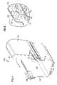
- FIG. 1is a perspective view of an embodiment of a trough system with a cover in a closed position made in accordance with the present invention.
- FIG. 2is an enlarged view of a portion of the trough system shown in FIG. 1 .
- FIG. 3is an enlarged view of another portion of the trough system shown in FIG. 1 .
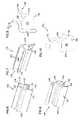
- FIG. 4is a perspective view of the trough system of FIG. 1 with the cover in an open position.
- FIG. 5is an enlarged view of a portion of the trough system shown in FIG. 4 .
- FIG. 6is a perspective view of an embodiment of a hinge clip made in accordance with the present invention.
- FIG. 7is another perspective view of the hinge clip of FIG. 6 .
- FIG. 8is an end view of the hinge clip of FIG. 6 .
- FIG. 9is a perspective view of an embodiment of a capture clip made in accordance with the present invention.
- FIG. 10is an end view of the capture clip of FIG. 9 .
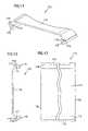
- FIG. 11is a perspective view of an embodiment of a cover made in accordance with the present invention.
- FIG. 12is an end view of the cover of FIG. 11 .
- FIG. 13is a bottom view of the cover of FIG. 11 .
- FIG. 14is a perspective view of another embodiment of a trough system with covers in closed positions made in accordance with the present invention.
- FIG. 15is an enlarged view of a portion of the trough system shown in FIG. 14 .
- FIG. 16is a perspective view of the trough system of FIG. 14 with the covers in open positions.
- FIG. 17is an enlarged view of a portion of the trough system shown in FIG. 16 .
- FIG. 18is a perspective view of another embodiment of a cover made in accordance with the present invention.
- FIG. 19is an end view of the cover of FIG. 18 .
- FIG. 20is a bottom view of the cover of FIG. 18 .
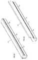
- FIG. 21is a perspective view of a trough system illustrating the entire cover of FIG. 1 .
- FIG. 22is a perspective view of the trough system of FIG. 21 with the cover in an open position.
- FIG. 23is another perspective view of the trough system of FIG. 22 .
- Embodiments of the present inventionare directed to covers for cable trough members.
- the coverscan be coupled to the trough members to cover the trough members.
- the coverscan be pivoted with respect to the trough members to provide access to the interior portions of the trough members.
- the term trough memberis used to refer to any trough, fitting, railway, raceway, or similarly configured component including any number of ends.
- the system 100generally includes a trough member 110 , a hinge clip 130 , a capture clip 150 , and a cover 170 .
- the clips 130 and 150can be coupled to the trough member 110 to hold the cover 170
- the hinge clip 130can allow the cover 170 to pivot relative to trough member 110 between closed and open positions.
- the cover 170is illustrated in the closed position in FIGS. 1-3 and in the open position in FIGS. 4 and 5 .
- the example trough member 110includes first and second sidewalls 112 and 116 coupled to a bottom wall 114 generally forming a trough with an interior space 118 through which cables such as fiber (e.g., fiber cables 101 shown in FIG. 1 ) can be run.
- the trough member 110also includes lips 310 and 311 creating a first slot 113 and lips 312 and 313 creating a second slot 117 positioned on the first and second sidewalls 112 and 116 , respectively.
- the lips 310 , 311 and 312 , 313 and first and second slots 113 and 117 created therebycan be used to allow components to be attached to the trough member 110 , as described further below.
- the trough member 110extends lengthwise from a first end 120 to a second end (not shown).
- the trough member 110can be of varying lengths and widths, and can be coupled to other trough members or similar structures to form a cable trough system.
- the example hinge clip 130shown in more detail in FIGS. 2 , 5 , and 6 - 8 , includes first and second members 133 and 134 creating a channel 131 to receive the lip 310 , and a clip portion 132 extends partially into the first slot 113 to couple the hinge clip 130 to the first sidewall 112 of the trough member 110 .
- the hinge clip 130further includes a hinge portion 135 having first and second arms 136 and 137 creating a socket 138 .
- the hinge clip 130can be coupled to the trough member 110 as shown in FIGS. 1 , 2 , 4 , and 5 , so that the channel 131 receives the lip 310 , and the clip portion 132 extends partially into the slot 113 .
- the hinge clip 130is coupled to the sidewall 112 by snapping the hinge clip 130 onto a mid-portion of the trough member 110 . This can be accomplished by positioning the channel 131 adjacent to the end of the sidewall 112 , and applying a downward force on the hinge clip 130 to cause the first member 133 to bow out slightly with respect to the second member 134 to allow the lip 310 to be received in the channel 131 and to allow the clip portion 132 to extend partially into the slot 113 .
- the hinge clip 130can be configured to be coupled to the sidewall 112 by sliding the hinge clip 130 onto an end, such as first end 120 of the trough member 110 , and into the desired position on the trough member 110 . If the hinge clip 130 is configured to be slid onto the trough member 110 , additional structure can be provided for fixing the hinge clip 130 in a desired position on the trough member 110 such as, for example, screws or bolts, as described further below.
- the hinge clip 130can be removed from the trough member 110 similarly, either by forcing the clip portion 132 out of the slot 113 and then removing the hinge clip 130 from the trough member 110 , or, alternatively, by sliding the hinge clip 130 off an end of the trough member 110 .
- the hinge clip 130extends from a first end 140 to a second end 142 .
- the length of the hinge clip 130i.e., the distance between ends 140 and 142
- the lengthis between 1 and 5 inches. In a preferred embodiment, the length is approximately 1.75 inches.
- the hinge clip 130is preferably molded from a plastic material such as, for example, a synthetic thermoplastic polymer such as an acrylonitrile-butadiene-styrene(ABS)/polycarbonate blend.
- ABSacrylonitrile-butadiene-styrene
- the hinge clip 130is injection molded and varies in thickness from one end to the other to allow the molded clip to be stripped from the mold. Other manufacturing methods and materials can also be used.
- the example capture clip 150shown in more detail in FIGS. 3 , 9 , and 10 , includes first and second members 153 and 154 , creating a channel 151 to receive the lip 312 , and a clip portion 152 extending partially with the slot 117 to couple the hinge clip 150 to the second sidewall 116 of the trough member 110 .
- the hinge clip 150further includes a ramp portion 155 and a seat 156 , as described further below.
- the capture clip 150can be coupled to the trough member 110 , as shown in FIGS. 1 and 3 , in a manner similar to that described above with respect to the hinge clip 130 .
- the capture clip 150can be coupled to the sidewall 116 by snapping the capture clip 150 onto the sidewall 116 so that the channel 151 receives the lip 312 , and the clip portion 152 extends partially into the slot 117 .
- the capture clip 150can be configured to be slid onto an end, such as first end 120 , and into the desired position on the trough member 110 .
- the capture clip 150can be removed from the trough member 110 similarly, either by forcing the clip portion 152 out of the slot 117 and then removing the capture clip 150 from the trough member 110 , or, alternatively, by sliding the capture clip 150 off an end of the trough member 110 .
- the capture clip 150extends from a first end 160 to a second end 162 .
- the length of the capture clip 150i.e., the distance between ends 160 and 162 ) is between 1 and 5 inches. In a preferred embodiment, the length is approximately 1.75 inches.
- the capture clip 150is preferably molded from a plastic material such as, for example, a synthetic thermoplastic polymer such as an acrylonitrile-butadiene-styrene(ABS)/polycarbonate blend.
- ABSacrylonitrile-butadiene-styrene
- the capture clip 150is injection molded and varies in thickness from one end to the other to allow the molded clip to be stripped from the mold. Other manufacturing methods and materials can also be used.
- the example cover 170shown in more detail in FIGS. 2 , 3 , 5 , and 11 - 13 , includes a main body 172 having first and second ends 174 and 176 . As illustrated by the depicted example, the ends 174 and 176 are preferably, but need not be, angled with respect to the main body 172 .
- the cover 170includes pivot members 178 and 179 at each of the first and second ends 174 and 176 .
- Each pivot member 178 and 179can, for example, be in the form of cylindrical bead, rod, shaft, or other similar shape including a generally round outer circumference. Grooves 173 and 175 with ends 177 are formed generally between the ends 174 and 176 and the outer circumference of the pivot members 178 and 179 .
- the cover 170extends from the first sidewall 112 to the second sidewall 116 to cover the open top of the trough member 110 .
- a width of the cover 170 between ends 174 and 176can be sized to cover the open top.
- the width of cover 170is 4, 6, or 12 inches, depending on the width of the trough member.
- the cover 170extends lengthwise from a first end 180 to a second end 182 .
- the length of the cover 170i.e., the distance between ends 180 and 182
- the lengthis approximately 6 feet.
- cover 170can be used end to end to cover trough members of longer length, and a cover 170 can be cut to other desired lengths.
- the cover 170is preferably extruded from a plastic material such as, for example, a synthetic thermoplastic polymer such as an acrylonitrile-butadiene-styrene(ABS)/polycarbonate blend, although other manufacturing methods (e.g., molding) and materials can also be used.
- ABSacrylonitrile-butadiene-styrene
- the cover 170is illustrated in the closed position. In this position, pivot member 178 of the cover 170 is positioned in the socket 138 of the hinge clip 130 . In addition, pivot member 179 of the cover 170 is positioned in the seat 156 of the capture clip 150 . In this position, the cover 170 extends over the open top of the trough member 110 and thereby protects any components (e.g., fiber cables) positioned in the interior space 118 of the trough member 110 from any debris dropped on the cover 170 .
- any componentse.g., fiber cables
- the cover 170can be pivoted from the closed position to the open position, This can be accomplished by applying force in a direction A on the second end 176 of the cover 170 , which causes the pivot member 179 to be released from the seat 156 of the capture clip 150 .
- the cover 170can then be pivoted about the pivot member 178 in the socket 138 of the hinge clip 130 in the direction A to the open position shown in FIGS. 4 and 5 .
- the first arm 136 of the socket 138 of the hinge portion 135is received in the groove 173 of the cover 170 to define the open position.
- the cover 170is prevented from pivoting further in the direction A, thereby maintaining the cover 170 in the open position and the pivot member 178 in the socket 138 .
- the cover 170can also be pivoted once again in a direction B back to the closed position.
- the pivot member 179contacts and rides along the ramp 155 of the capture clip 150 , which directs the pivot member 179 into the seat 156 .
- sidewall 116 that is coupled to the capture clip 150bows inward slightly, allowing the pivot member 179 to clear the ramp 155 and drop into the seat 156 . In this manner, a snug fit between the cover 170 and the capture clip 150 can be created, and the capture clip 150 can preferably maintain the cover 170 in the closed position.
- the cover 170is once again in the closed position, as shown in FIGS. 1-3 .
- An example method of assembling the trough system 100is as follows. Initially, the hinge clip 130 and the capture clip 150 are positioned on the trough member 110 . This can be accomplished, as described above, preferably by snapping the hinge clip 130 and capture clip 150 onto the trough member 110 at the desired locations. Preferably, once the hinge clip 130 and capture clip 150 are positioned on the trough member 110 , the clips 130 and 150 can be slid slightly with respect to the trough member 110 to further position the clips 130 and 150 as desired on the trough member 110 .
- multiple hinge clips 130 and capture clips 150are used. For example, if a 6 foot cover is to be used, preferably three hinge clips 130 and three capture clips 150 are positioned on opposite sidewalls of the trough member 110 at spaced intervals, as shown in FIGS. 21-23 . More or fewer hinge and capture clips can also be used. In preferred embodiments, the hinge clips 130 and capture clips 150 are spaced at between approximately 1 and 3 feet intervals, more preferably at approximately 2 feet intervals. Each hinge clip 130 can be positioned across from each capture clip 150 (as shown in the example of FIGS. 21-23 ), or the clips can be staggered as desired.
- the cover 170can be placed over the open top of the trough member 110 , and the cover 170 can be pressed downward toward the trough member 110 to snap the pivot member 178 into the sockets 138 of the hinge clips 130 and the pivot member 179 into the seats 156 of the capture clips 150 .
- the cover 170can be pivoted between the closed and open positions as described above.
- FIGS. 14-20another example embodiment of a trough system 200 is shown.
- the system 200including hinge clip 130 , is similar to the system 100 , with the differences noted below.
- cover portions 272 and 274are provided instead of a single cover (such as cover 170 provided in system 100 ). As shown in FIG. 14 , cover portions 272 and 274 each extend partially across the open top of the trough member 110 . Although ends 276 of the cover portions 272 and 274 extend closed to one another, preferably a slot 230 is formed between ends 276 , as described further below.
- a pivot member 279(similar to pivot members 178 and 179 ) is positioned at an end 290 of the cover portion 274 .
- a first groove 294 with end 275is formed between an outer circumference of the pivot member 279 and the end 290 (similar to groove 173 ), and a second groove 296 with end 277 is formed between the pivot member 279 and a member 292 .
- end 276 of the cover portion 274can be formed with a rounded surface (see FIGS. 14 , 16 , and 18 - 20 ) to minimize any sharp edges. This can be advantageous, for example, to minimize any wear on fiber cables if the cables are run through the slot 230 with the cover portions 272 and 274 in the closed position.
- the pivot member 279 of the cover portion 274can be received in the socket 138 of the hinge clip 130 .
- the second arm 137 of the socket 138contacts end 277 of the groove 296 to define the closed position.
- the cover portion 274can be pivoted into the open position by applying force to the end 276 in the direction A.
- the first arm 136 of the socket 138contacts end 275 of the groove 294 to define the open position and prevent the cover portion 274 from being pivoted further in the direction A.
- the cover portion 274can be pivoted back to the closed position by applying a force to pivot the cover portion 274 in the direction B.
- the cover portion 274can be pivoted in the direction B, as described above, until the second arm 137 of the socket 138 contacts end 277 of the groove 296 in the closed position.
- the cover portion 272is preferably configured as a mirror image of the cover portion 274 and functions in a similar manner. As shown, no capture clip 150 is used for system 200 . Instead, an additional hinge clip 130 is provided to hold the pivot member of the cover portion 272 .
- the slot 230 between cover portions 272 and 274is less than 1 inch, more preferably 0.75 inch, and even more preferably approximately 0.5 inch or less.
- the slot 230allows limited access to the interior space 118 of the trough member 110 without requiring that any covers be opened or removed.
- additional fiberscan be introduced into the interior space 118 of the trough member 110 by insertion through the slot 230 without requiring that either cover portions 272 or 274 be opened.
- the slot 230is preferably small enough to prevent most material from entering the interior space 118 of the trough member 110 when cover portions 272 and 274 are in the closed positions.
- An example method of assembling the system 200is as follows. First, the hinge clips 130 are positioned on the trough member 110 in a manner as described above. Then, the pivot members 279 of each of the cover portions 272 and 274 are inserted into the sockets 138 of the hinge clips 130 to couple the cover portions 272 and 274 to the trough member 110 .
- Each cover portion 272 and 274can be opened and closed separately or in unison as described above.
- the example cable trough systems 100 and 200can exhibit a variety of advantages.
- the hinge and capture clipscan be coupled to existing trough members to allow pivoting covers to be added the trough members.
- the hinge and capture clipsare preferably configured to snap onto the trough member without requiring the clips to be slid onto the trough member, and without requiring additional hardware such as screws or bolts to hold the clips in place on the trough member.
- additional hardwarecan be used to, for example, lock the hinge and capture clips in place on the trough member.
- the hinge and/or capture clipscan be formed as an integral part of the trough member.
- the coveris preferably configured to be easily snapped onto the hinge and capture clips without requiring the cover to be slid through the clips. This can be advantageous so that the cover can be easily coupled to the trough member.
- the systems 100 and 200 described abovecan also be advantageous in that they can be configured to meet a variety of standards associated with cable trough systems.
- the hinge and capture clipscan be configured to hold the covers disclosed herein in close proximity to upper ends of the sidewalls of the trough member such that a 0.125 inch probe cannot be inserted into the interior space of the trough member, as required by UL Specification 60950, Safety of Information Technology Equipment.
- the slot formed between the cover portions of system 200can be sized to allow access to the interior space of the trough member while preventing most debris from entering.
- a slot of approximately 0.5 inch between cover portionscan prevent the handle of a typically-sized screw driver from entering the interior space of the trough member when dropped on the closed cover portions, while still allowing fiber cables to be run into the interior space without requiring the covers to be opened.
- the systems 100 and 200can be advantageous in that the covers can be snapped or propped in the closed position and propped into the open position without requiring additional components beyond the hinge clips (and preferably capture clips for system 100 ) to be added to either the sidewalls or interior space of the trough member.
Landscapes
- Engineering & Computer Science (AREA)
- Architecture (AREA)
- Civil Engineering (AREA)
- Structural Engineering (AREA)
- Laying Of Electric Cables Or Lines Outside (AREA)
- Closures For Containers (AREA)
Abstract
Description
Claims (4)
Priority Applications (1)
| Application Number | Priority Date | Filing Date | Title |
|---|---|---|---|
| US11/276,593US7411126B2 (en) | 2003-11-05 | 2006-03-07 | Cover for cable trough |
Applications Claiming Priority (3)
| Application Number | Priority Date | Filing Date | Title |
|---|---|---|---|
| US10/703,157US6835891B1 (en) | 2003-11-05 | 2003-11-05 | Cover for cable trough |
| US11/011,735US7060901B2 (en) | 2003-11-05 | 2004-12-14 | Cover for cable trough |
| US11/276,593US7411126B2 (en) | 2003-11-05 | 2006-03-07 | Cover for cable trough |
Related Parent Applications (1)
| Application Number | Title | Priority Date | Filing Date |
|---|---|---|---|
| US11/011,735ContinuationUS7060901B2 (en) | 2003-11-05 | 2004-12-14 | Cover for cable trough |
Publications (2)
| Publication Number | Publication Date |
|---|---|
| US20060191700A1 US20060191700A1 (en) | 2006-08-31 |
| US7411126B2true US7411126B2 (en) | 2008-08-12 |
Family
ID=33518229
Family Applications (3)
| Application Number | Title | Priority Date | Filing Date |
|---|---|---|---|
| US10/703,157Expired - LifetimeUS6835891B1 (en) | 2003-11-05 | 2003-11-05 | Cover for cable trough |
| US11/011,735Expired - LifetimeUS7060901B2 (en) | 2003-11-05 | 2004-12-14 | Cover for cable trough |
| US11/276,593Expired - LifetimeUS7411126B2 (en) | 2003-11-05 | 2006-03-07 | Cover for cable trough |
Family Applications Before (2)
| Application Number | Title | Priority Date | Filing Date |
|---|---|---|---|
| US10/703,157Expired - LifetimeUS6835891B1 (en) | 2003-11-05 | 2003-11-05 | Cover for cable trough |
| US11/011,735Expired - LifetimeUS7060901B2 (en) | 2003-11-05 | 2004-12-14 | Cover for cable trough |
Country Status (2)
| Country | Link |
|---|---|
| US (3) | US6835891B1 (en) |
| CN (2) | CN100463316C (en) |
Cited By (21)
| Publication number | Priority date | Publication date | Assignee | Title |
|---|---|---|---|---|
| US20090032651A1 (en)* | 2007-08-01 | 2009-02-05 | Derek Sayres | Hinge for Cable Trough Cover |
| US20090032280A1 (en)* | 2007-08-01 | 2009-02-05 | Owens Ryan J | Hinge for Cable Trough Cover |
| US20100263902A1 (en)* | 2009-04-20 | 2010-10-21 | Adc Telecommunications, Inc. | Offset Slotting for Cable Trough Member |
| US20100266256A1 (en)* | 2009-04-20 | 2010-10-21 | Adc Telecommunications, Inc. | Fiber Retainer for Cable Trough Member |
| US20110011612A1 (en)* | 2009-07-15 | 2011-01-20 | Derek Sayres | Twist-in latching arrangement for cable management structure |
| US20110057076A1 (en)* | 2009-09-08 | 2011-03-10 | Panduit Corp. | Cover For Cable Fitting Base |
| US8667908B2 (en) | 2010-06-02 | 2014-03-11 | Steelcase Inc. | Frame type table assemblies |
| US8689705B2 (en) | 2010-06-02 | 2014-04-08 | Steelcase, Inc. | Reconfigurable table assemblies |
| US9185974B2 (en) | 2010-06-02 | 2015-11-17 | Steelcase Inc. | Frame type workstation configurations |
| US9210999B2 (en) | 2010-06-02 | 2015-12-15 | Steelcase Inc. | Frame type table assemblies |
| US10039374B2 (en) | 2016-05-13 | 2018-08-07 | Steelcase Inc. | Multi-tiered workstation assembly |
| US10103528B2 (en) | 2016-06-30 | 2018-10-16 | Hellermanntyton Corporation | Cable duct |
| US10444459B2 (en) | 2015-10-19 | 2019-10-15 | Commscope Technologies Llc | Articulating optical fiber guide system |
| US10517392B2 (en) | 2016-05-13 | 2019-12-31 | Steelcase Inc. | Multi-tiered workstation assembly |
| US10862283B1 (en)* | 2019-06-06 | 2020-12-08 | FSR, Inc. | Raceway for electrical and connectivity cables |
| US11002384B2 (en) | 2019-08-19 | 2021-05-11 | Cablofil, Inc. | Cable conveyance system |
| US11114217B2 (en)* | 2017-01-12 | 2021-09-07 | Sumitomo Wiring Systems, Ltd. | Shield conduction path |
| US11539194B2 (en) | 2019-03-25 | 2022-12-27 | Hellermanntyton Corporation | Cable duct assembly |
| US11777287B1 (en) | 2022-06-30 | 2023-10-03 | Cablofil, Inc. | Cable tray having cover panels |
| US12298581B2 (en) | 2020-01-29 | 2025-05-13 | Afl Telecommunications Llc | Terminal enclosure for a telecommunications system |
| US12376677B1 (en) | 2012-10-10 | 2025-08-05 | Steelcase Inc. | Ergonomic seating system, tilt-lock control and remote powering method and apparatus |
Families Citing this family (77)
| Publication number | Priority date | Publication date | Assignee | Title |
|---|---|---|---|---|
| DE10057556A1 (en)* | 2000-11-21 | 2002-05-23 | Kreuzer Gmbh & Co Ohg | Tripod head for medical surveillance and treatment systems with carrier profile and apparatus carriage |
| US6810191B2 (en)* | 2001-07-20 | 2004-10-26 | Adc Telecommunications, Inc. | Cable trough cover |
| TWI232672B (en)* | 2003-05-14 | 2005-05-11 | Benq Corp | A hinge for connecting the book cover of an electric device |
| US7077467B2 (en)* | 2003-08-14 | 2006-07-18 | Be Aerospace, Inc. | Cable raceway |
| US7434769B1 (en)* | 2003-09-23 | 2008-10-14 | O.C. White Co. | Articulated channel arm |
| US7041897B2 (en)* | 2004-02-10 | 2006-05-09 | Adc Telecommunications, Inc. | Hinge for cable trough cover |
| US6835891B1 (en)* | 2003-11-05 | 2004-12-28 | Adc Telecommunications, Inc. | Cover for cable trough |
| US6968647B2 (en)* | 2003-12-01 | 2005-11-29 | Levesque Stewart A | Rack-mounted door assembly with alternative pivoting axes |
| DE102004013010B3 (en)* | 2004-03-16 | 2005-11-03 | A. Raymond & Cie | Device for holding elongated objects |
| USD539228S1 (en)* | 2005-01-24 | 2007-03-27 | Hoffman Enclosures, Inc. | Vertical cable manager |
| KR101136862B1 (en)* | 2006-05-29 | 2012-04-20 | 삼성전자주식회사 | Electric wire hiding device and electric apparatus having the same |
| US7742675B2 (en)* | 2007-01-26 | 2010-06-22 | Adc Telecommunications, Inc. | Cable trough system and method |
| ITTO20070754A1 (en)* | 2007-10-24 | 2009-04-25 | Serint Di Racca Mauro E C S A | CABLE CARRIAGE AND RELATIVE REALIZATION METHOD |
| US7673835B2 (en)* | 2007-12-07 | 2010-03-09 | Adc Telecommunications, Inc. | Telescoping cover for cable trough system |
| US8233763B2 (en)* | 2007-12-07 | 2012-07-31 | Adc Telecommunications, Inc. | Flexible cover for cable trough system |
| US9441337B2 (en)* | 2007-12-17 | 2016-09-13 | Michael John Lamore | Cable housing system |
| US8217266B2 (en)* | 2008-02-12 | 2012-07-10 | Panduit Corp. | Rail wiring duct |
| US20090273260A1 (en)* | 2008-05-02 | 2009-11-05 | Innovant, Inc. | Adaptable cable management desk system |
| WO2009154956A2 (en) | 2008-05-28 | 2009-12-23 | Steelcase Inc. | Worksurface assembly |
| US8083302B2 (en)* | 2008-06-11 | 2011-12-27 | Adc Telecommunications, Inc. | L-shaped doors with trapezoidal seal |
| US7719856B2 (en)* | 2008-06-11 | 2010-05-18 | Adc Telecommunications, Inc. | Cam shaped hinges |
| US8452148B2 (en) | 2008-08-29 | 2013-05-28 | Corning Cable Systems Llc | Independently translatable modules and fiber optic equipment trays in fiber optic equipment |
| US11294136B2 (en) | 2008-08-29 | 2022-04-05 | Corning Optical Communications LLC | High density and bandwidth fiber optic apparatuses and related equipment and methods |
| US8205309B2 (en)* | 2008-12-08 | 2012-06-26 | The Boeing Company | Clamps for supporting transport system structures |
| EP2221932B1 (en)* | 2009-02-24 | 2011-11-16 | CCS Technology Inc. | Holding device for a cable or an assembly for use with a cable |
| US8699838B2 (en) | 2009-05-14 | 2014-04-15 | Ccs Technology, Inc. | Fiber optic furcation module |
| US8538226B2 (en) | 2009-05-21 | 2013-09-17 | Corning Cable Systems Llc | Fiber optic equipment guides and rails configured with stopping position(s), and related equipment and methods |
| US9075216B2 (en) | 2009-05-21 | 2015-07-07 | Corning Cable Systems Llc | Fiber optic housings configured to accommodate fiber optic modules/cassettes and fiber optic panels, and related components and methods |
| EP2443497B1 (en) | 2009-06-19 | 2020-03-04 | Corning Cable Systems LLC | High density and bandwidth fiber optic apparatus |
| US8712206B2 (en) | 2009-06-19 | 2014-04-29 | Corning Cable Systems Llc | High-density fiber optic modules and module housings and related equipment |
| GB2474906A (en)* | 2009-11-02 | 2011-05-04 | Alan Anthony Farrell | Support Flange |
| US8625950B2 (en) | 2009-12-18 | 2014-01-07 | Corning Cable Systems Llc | Rotary locking apparatus for fiber optic equipment trays and related methods |
| US8992099B2 (en) | 2010-02-04 | 2015-03-31 | Corning Cable Systems Llc | Optical interface cards, assemblies, and related methods, suited for installation and use in antenna system equipment |
| US8913866B2 (en) | 2010-03-26 | 2014-12-16 | Corning Cable Systems Llc | Movable adapter panel |
| CA2796221C (en) | 2010-04-16 | 2018-02-13 | Ccs Technology, Inc. | Sealing and strain relief device for data cables |
| EP2381284B1 (en) | 2010-04-23 | 2014-12-31 | CCS Technology Inc. | Under floor fiber optic distribution device |
| US9519118B2 (en) | 2010-04-30 | 2016-12-13 | Corning Optical Communications LLC | Removable fiber management sections for fiber optic housings, and related components and methods |
| US8705926B2 (en) | 2010-04-30 | 2014-04-22 | Corning Optical Communications LLC | Fiber optic housings having a removable top, and related components and methods |
| US9632270B2 (en) | 2010-04-30 | 2017-04-25 | Corning Optical Communications LLC | Fiber optic housings configured for tool-less assembly, and related components and methods |
| US9720195B2 (en) | 2010-04-30 | 2017-08-01 | Corning Optical Communications LLC | Apparatuses and related components and methods for attachment and release of fiber optic housings to and from an equipment rack |
| US8660397B2 (en) | 2010-04-30 | 2014-02-25 | Corning Cable Systems Llc | Multi-layer module |
| US8879881B2 (en) | 2010-04-30 | 2014-11-04 | Corning Cable Systems Llc | Rotatable routing guide and assembly |
| US9075217B2 (en) | 2010-04-30 | 2015-07-07 | Corning Cable Systems Llc | Apparatuses and related components and methods for expanding capacity of fiber optic housings |
| WO2011150192A2 (en) | 2010-05-28 | 2011-12-01 | Steelcase Inc. | Grommet assembly for work surfaces |
| US8718436B2 (en) | 2010-08-30 | 2014-05-06 | Corning Cable Systems Llc | Methods, apparatuses for providing secure fiber optic connections |
| US9279951B2 (en) | 2010-10-27 | 2016-03-08 | Corning Cable Systems Llc | Fiber optic module for limited space applications having a partially sealed module sub-assembly |
| US8662760B2 (en) | 2010-10-29 | 2014-03-04 | Corning Cable Systems Llc | Fiber optic connector employing optical fiber guide member |
| US9116324B2 (en) | 2010-10-29 | 2015-08-25 | Corning Cable Systems Llc | Stacked fiber optic modules and fiber optic equipment configured to support stacked fiber optic modules |
| CA2819235C (en) | 2010-11-30 | 2018-01-16 | Corning Cable Systems Llc | Fiber device holder and strain relief device |
| GB2486682B (en)* | 2010-12-22 | 2016-08-10 | Tyco Electronics Ltd Uk | A cable breakout support |
| WO2012106510A2 (en) | 2011-02-02 | 2012-08-09 | Corning Cable Systems Llc | Dense fiber optic connector assemblies and related connectors and cables suitable for establishing optical connections for optical backplanes in equipment racks |
| US9008485B2 (en) | 2011-05-09 | 2015-04-14 | Corning Cable Systems Llc | Attachment mechanisms employed to attach a rear housing section to a fiber optic housing, and related assemblies and methods |
| AU2012275598A1 (en) | 2011-06-30 | 2014-01-16 | Corning Optical Communications LLC | Fiber optic equipment assemblies employing non-U-width-sized housings and related methods |
| US8953924B2 (en) | 2011-09-02 | 2015-02-10 | Corning Cable Systems Llc | Removable strain relief brackets for securing fiber optic cables and/or optical fibers to fiber optic equipment, and related assemblies and methods |
| US9038832B2 (en) | 2011-11-30 | 2015-05-26 | Corning Cable Systems Llc | Adapter panel support assembly |
| CN103178473A (en)* | 2011-12-26 | 2013-06-26 | 上海华伟塑胶有限公司 | Integrated wiring duct |
| US9250409B2 (en) | 2012-07-02 | 2016-02-02 | Corning Cable Systems Llc | Fiber-optic-module trays and drawers for fiber-optic equipment |
| US9042702B2 (en) | 2012-09-18 | 2015-05-26 | Corning Cable Systems Llc | Platforms and systems for fiber optic cable attachment |
| ES2551077T3 (en) | 2012-10-26 | 2015-11-16 | Ccs Technology, Inc. | Fiber optic management unit and fiber optic distribution device |
| US9565928B2 (en)* | 2012-11-02 | 2017-02-14 | Paragon Furniture, Lp | Desktop organization and display stand system |
| US8985862B2 (en) | 2013-02-28 | 2015-03-24 | Corning Cable Systems Llc | High-density multi-fiber adapter housings |
| DE102013019389A1 (en)* | 2013-11-18 | 2015-05-21 | GM Global Technology Operations LLC (n. d. Ges. d. Staates Delaware) | Lockable device for storing objects in a vehicle |
| US9791245B1 (en) | 2013-12-18 | 2017-10-17 | Michael John Lamore | Building protection barrier system |
| US9466959B2 (en)* | 2014-01-24 | 2016-10-11 | Ortronics, Inc. | Pathway cable guide |
| US9303440B2 (en) | 2014-06-13 | 2016-04-05 | Ortronics, Inc. | Door assembly |
| SG11201607561TA (en)* | 2015-06-15 | 2017-01-27 | Dirtt Environmental Solutions | Modular furniture system with wire management |
| CA2950839C (en)* | 2016-01-30 | 2023-09-12 | Cooper Technologies Company | Equipment rack and components thereof |
| US10117351B2 (en)* | 2016-07-27 | 2018-10-30 | Martas Precision Slide Co., Ltd. | Cable management arm |
| JP6404870B2 (en)* | 2016-08-09 | 2018-10-17 | アイシン精機株式会社 | Air tube holding member for seat |
| CN107205325A (en)* | 2017-06-30 | 2017-09-26 | 苏州广能电子科技有限公司 | Hairbrush anticreep console |
| CN107155278A (en)* | 2017-06-30 | 2017-09-12 | 苏州广能电子科技有限公司 | Clean console |
| CN107404816A (en)* | 2017-06-30 | 2017-11-28 | 苏州广能电子科技有限公司 | Console |
| MX2021008562A (en)* | 2019-01-22 | 2021-10-13 | Bendpak Inc | Three-level vehicle lift. |
| US11715944B1 (en) | 2019-01-22 | 2023-08-01 | Titan3 Technology LLC | Expandable cord protector |
| US11706894B2 (en)* | 2019-08-05 | 2023-07-18 | Panduit Corp. | Cable manager with a hinged door |
| US12416153B2 (en)* | 2020-06-15 | 2025-09-16 | The Azek Group Llc | Multifunctional design housing components |
| US11605938B2 (en)* | 2020-06-19 | 2023-03-14 | Abb Schweiz Ag | Perforated tray splicing system |
Citations (45)
| Publication number | Priority date | Publication date | Assignee | Title |
|---|---|---|---|---|
| GB1021871A (en) | 1962-01-23 | 1966-03-09 | Power Ct Company Ltd | Improvements in and relating to trunking for electrical installations |
| US3786171A (en) | 1973-01-22 | 1974-01-15 | Kvoda Plastics Ltd | Integral hinged wiring raceway |
| FR2406327A1 (en) | 1977-10-17 | 1979-05-11 | Planet Wattohm Sa | Fastening for cover of cable duct - comprises inwardly projecting rib on cover engaging outwardly projecting rib on duct wall |
| FR2425518A1 (en) | 1978-05-11 | 1979-12-07 | Villi Canalplast | Floor or wall mounted duct for electric cables - has square section with top consisting of pivotable clip-on cover |
| USD269968S (en) | 1980-02-29 | 1983-08-02 | Aparellaje Electrico, S.A. | Ducting for electric cables |
| US4406379A (en) | 1982-06-11 | 1983-09-27 | Westinghouse Electric Corp. | Cable manager |
| US4423284A (en) | 1982-06-04 | 1983-12-27 | Kaplan Steve E | Moulding duct |
| US4634019A (en) | 1986-03-14 | 1987-01-06 | J. L. Clark Manufacturing Co. | Container with plastic hinge |
| US4640314A (en) | 1984-07-23 | 1987-02-03 | Kirkhill Rubber Company | Enclosed conduit |
| US4942271A (en) | 1988-12-07 | 1990-07-17 | Hubbell Incorporated | Hinged plastic duct for conduit |
| US5004192A (en) | 1988-08-02 | 1991-04-02 | Isidore Handler | Side supported cable tray |
| US5134250A (en) | 1991-04-10 | 1992-07-28 | Panduit Corp. | Wiring duct |
| US5235136A (en) | 1991-07-24 | 1993-08-10 | Dek, Inc. | One-piece reclosable cable and wire duct |
| WO1995028757A1 (en) | 1994-04-16 | 1995-10-26 | Albert Ackermann Gmbh & Co. Kg | Installation housing |
| US5669106A (en) | 1996-06-21 | 1997-09-23 | Lucent Technologies Inc. | Hinge mechanism |
| US5728976A (en) | 1996-05-22 | 1998-03-17 | Dek, Inc. | Detachable cover for wire ducts having a living hinge |
| US5942729A (en) | 1997-08-04 | 1999-08-24 | The Siemon Company | Double hinged raceway |
| US6084180A (en) | 1993-11-15 | 2000-07-04 | Debartolo, Jr.; Joseph V. | Multi-channel duct for power and tel/com conductors |
| US6107576A (en) | 1998-02-26 | 2000-08-22 | Newton Instruments Company, Inc. | Hinged top lid for cable channel |
| US6107575A (en) | 1996-06-24 | 2000-08-22 | Hilti Aktiengesellschaft | Cable channel section |
| USD430543S (en) | 2000-02-07 | 2000-09-05 | Panduit Corp. | Raceway cover |
| EP1033800A1 (en) | 1999-03-03 | 2000-09-06 | Panduit Corporation | Wireway system having a pivotable cover |
| US6288331B1 (en) | 1996-11-28 | 2001-09-11 | Udo Wirthwein | Cable duct and cover |
| US6333461B1 (en) | 1999-09-24 | 2001-12-25 | Planet Wattohm | Electrical wiring trunking with flexible hinge |
| US6348660B1 (en) | 1998-05-20 | 2002-02-19 | Ditto Sales, Inc. | Electrical raceway assembly |
| WO2002018992A1 (en) | 2000-08-28 | 2002-03-07 | Telect, Inc. | Fiber trough junction cover system |
| WO2002029463A1 (en) | 2000-08-28 | 2002-04-11 | Telect, Inc. | Fiber trough cover system |
| US6380484B1 (en) | 1996-11-12 | 2002-04-30 | Ergotron, Inc. | Cable routing duct |
| US6437244B1 (en) | 2000-06-05 | 2002-08-20 | Panduit Corp. | Wiring duct system hinge arrangement |
| US6459038B1 (en) | 2001-08-29 | 2002-10-01 | Panduit Corp. | Two-piece up-spout fitting for wiring duct |
| US6476327B1 (en) | 2000-06-01 | 2002-11-05 | Panduit Corp. | Split fiber cover and raceway fitting |
| US20030016931A1 (en) | 2001-07-20 | 2003-01-23 | Ferris Matthew D. | Cable trough cover |
| EP1284535A1 (en) | 2001-08-18 | 2003-02-19 | Tehalit GmbH & Co. KG | Installation duct |
| USD473850S1 (en) | 2002-05-22 | 2003-04-29 | Panduit Corp. | Raceway cover |
| US20030089515A1 (en) | 2001-10-31 | 2003-05-15 | Hellermann Tyton Corporation | Multi-channel raceway |
| EP1317040A1 (en) | 2001-11-28 | 2003-06-04 | Dirk A. Brügmann Kunststoff-Verarbeitung GmbH & Co. KG | Cable duct |
| US6693238B2 (en) | 2001-02-05 | 2004-02-17 | Legrand | Trunking accessory and a combination including the accessory and trunking with a base section specifically adapted to suit the accessory |
| US6792877B2 (en) | 1998-05-20 | 2004-09-21 | Ditto Sales, Inc. | Electrical raceway assembly |
| US6803519B2 (en) | 2002-08-07 | 2004-10-12 | Thomas & Betts International, Inc. | Latching and assembly structure of a cover and duct base in a wiring duct assembly |
| US6835891B1 (en) | 2003-11-05 | 2004-12-28 | Adc Telecommunications, Inc. | Cover for cable trough |
| USRE38709E1 (en) | 1998-05-20 | 2005-03-08 | Ditto Sales, Inc. | Electrical raceway assembly |
| US6903265B1 (en) | 2004-05-27 | 2005-06-07 | Panduit Corp. | Hinged and latched raceway |
| US6916986B1 (en) | 2004-05-05 | 2005-07-12 | Adc Telecommunications, Inc. | Hinge for cable trough cover |
| US7041897B2 (en)* | 2004-02-10 | 2006-05-09 | Adc Telecommunications, Inc. | Hinge for cable trough cover |
| US7041912B2 (en) | 2001-11-20 | 2006-05-09 | Wien Kanal-Abwassertechnologie Gesmbh | Installation and cover device for cables and methods for installation thereof |
- 2003
- 2003-11-05USUS10/703,157patent/US6835891B1/ennot_activeExpired - Lifetime
- 2004
- 2004-10-13CNCNB200480031983XApatent/CN100463316C/ennot_activeExpired - Fee Related
- 2004-10-13CNCN2008101698975Apatent/CN101394070B/ennot_activeExpired - Fee Related
- 2004-12-14USUS11/011,735patent/US7060901B2/ennot_activeExpired - Lifetime
- 2006
- 2006-03-07USUS11/276,593patent/US7411126B2/ennot_activeExpired - Lifetime
Patent Citations (53)
| Publication number | Priority date | Publication date | Assignee | Title |
|---|---|---|---|---|
| GB1021871A (en) | 1962-01-23 | 1966-03-09 | Power Ct Company Ltd | Improvements in and relating to trunking for electrical installations |
| US3786171A (en) | 1973-01-22 | 1974-01-15 | Kvoda Plastics Ltd | Integral hinged wiring raceway |
| FR2406327A1 (en) | 1977-10-17 | 1979-05-11 | Planet Wattohm Sa | Fastening for cover of cable duct - comprises inwardly projecting rib on cover engaging outwardly projecting rib on duct wall |
| FR2425518A1 (en) | 1978-05-11 | 1979-12-07 | Villi Canalplast | Floor or wall mounted duct for electric cables - has square section with top consisting of pivotable clip-on cover |
| USD269968S (en) | 1980-02-29 | 1983-08-02 | Aparellaje Electrico, S.A. | Ducting for electric cables |
| US4423284A (en) | 1982-06-04 | 1983-12-27 | Kaplan Steve E | Moulding duct |
| US4406379A (en) | 1982-06-11 | 1983-09-27 | Westinghouse Electric Corp. | Cable manager |
| US4640314A (en) | 1984-07-23 | 1987-02-03 | Kirkhill Rubber Company | Enclosed conduit |
| US4634019A (en) | 1986-03-14 | 1987-01-06 | J. L. Clark Manufacturing Co. | Container with plastic hinge |
| US5004192A (en) | 1988-08-02 | 1991-04-02 | Isidore Handler | Side supported cable tray |
| US4942271A (en) | 1988-12-07 | 1990-07-17 | Hubbell Incorporated | Hinged plastic duct for conduit |
| US5134250A (en) | 1991-04-10 | 1992-07-28 | Panduit Corp. | Wiring duct |
| US5235136A (en) | 1991-07-24 | 1993-08-10 | Dek, Inc. | One-piece reclosable cable and wire duct |
| US6084180A (en) | 1993-11-15 | 2000-07-04 | Debartolo, Jr.; Joseph V. | Multi-channel duct for power and tel/com conductors |
| WO1995028757A1 (en) | 1994-04-16 | 1995-10-26 | Albert Ackermann Gmbh & Co. Kg | Installation housing |
| US5728976A (en) | 1996-05-22 | 1998-03-17 | Dek, Inc. | Detachable cover for wire ducts having a living hinge |
| US5669106A (en) | 1996-06-21 | 1997-09-23 | Lucent Technologies Inc. | Hinge mechanism |
| US6107575A (en) | 1996-06-24 | 2000-08-22 | Hilti Aktiengesellschaft | Cable channel section |
| US6380484B1 (en) | 1996-11-12 | 2002-04-30 | Ergotron, Inc. | Cable routing duct |
| US6288331B1 (en) | 1996-11-28 | 2001-09-11 | Udo Wirthwein | Cable duct and cover |
| US5942729A (en) | 1997-08-04 | 1999-08-24 | The Siemon Company | Double hinged raceway |
| US6107576A (en) | 1998-02-26 | 2000-08-22 | Newton Instruments Company, Inc. | Hinged top lid for cable channel |
| US6348660B1 (en) | 1998-05-20 | 2002-02-19 | Ditto Sales, Inc. | Electrical raceway assembly |
| USRE38709E1 (en) | 1998-05-20 | 2005-03-08 | Ditto Sales, Inc. | Electrical raceway assembly |
| US6792877B2 (en) | 1998-05-20 | 2004-09-21 | Ditto Sales, Inc. | Electrical raceway assembly |
| EP1033800A1 (en) | 1999-03-03 | 2000-09-06 | Panduit Corporation | Wireway system having a pivotable cover |
| US6437243B1 (en) | 1999-03-03 | 2002-08-20 | Panduit Corp. | Wireway system having a pivotable cover |
| US6333461B1 (en) | 1999-09-24 | 2001-12-25 | Planet Wattohm | Electrical wiring trunking with flexible hinge |
| USD430543S (en) | 2000-02-07 | 2000-09-05 | Panduit Corp. | Raceway cover |
| US20030047345A1 (en) | 2000-06-01 | 2003-03-13 | Bernard William A. | Split fiber cover and raceway fitting |
| US6476327B1 (en) | 2000-06-01 | 2002-11-05 | Panduit Corp. | Split fiber cover and raceway fitting |
| US6677533B2 (en) | 2000-06-01 | 2004-01-13 | Panduit Corp. | Split fiber cover and raceway fitting |
| US6437244B1 (en) | 2000-06-05 | 2002-08-20 | Panduit Corp. | Wiring duct system hinge arrangement |
| WO2002018992A1 (en) | 2000-08-28 | 2002-03-07 | Telect, Inc. | Fiber trough junction cover system |
| WO2002029463A1 (en) | 2000-08-28 | 2002-04-11 | Telect, Inc. | Fiber trough cover system |
| US6668123B1 (en) | 2000-08-28 | 2003-12-23 | Telect, Inc. | Fiber trough junction cover system |
| US6693238B2 (en) | 2001-02-05 | 2004-02-17 | Legrand | Trunking accessory and a combination including the accessory and trunking with a base section specifically adapted to suit the accessory |
| US20040218884A1 (en) | 2001-07-20 | 2004-11-04 | Adc Telecommunications, Inc. | Cable trough cover |
| US6810191B2 (en) | 2001-07-20 | 2004-10-26 | Adc Telecommunications, Inc. | Cable trough cover |
| US20030016931A1 (en) | 2001-07-20 | 2003-01-23 | Ferris Matthew D. | Cable trough cover |
| EP1284535A1 (en) | 2001-08-18 | 2003-02-19 | Tehalit GmbH & Co. KG | Installation duct |
| US6459038B1 (en) | 2001-08-29 | 2002-10-01 | Panduit Corp. | Two-piece up-spout fitting for wiring duct |
| US20030089515A1 (en) | 2001-10-31 | 2003-05-15 | Hellermann Tyton Corporation | Multi-channel raceway |
| US6972367B2 (en) | 2001-10-31 | 2005-12-06 | Hellermanntyton Corporation | Multi-channel raceway |
| US7041912B2 (en) | 2001-11-20 | 2006-05-09 | Wien Kanal-Abwassertechnologie Gesmbh | Installation and cover device for cables and methods for installation thereof |
| EP1317040A1 (en) | 2001-11-28 | 2003-06-04 | Dirk A. Brügmann Kunststoff-Verarbeitung GmbH & Co. KG | Cable duct |
| USD473850S1 (en) | 2002-05-22 | 2003-04-29 | Panduit Corp. | Raceway cover |
| US6803519B2 (en) | 2002-08-07 | 2004-10-12 | Thomas & Betts International, Inc. | Latching and assembly structure of a cover and duct base in a wiring duct assembly |
| US6835891B1 (en) | 2003-11-05 | 2004-12-28 | Adc Telecommunications, Inc. | Cover for cable trough |
| US7060901B2 (en)* | 2003-11-05 | 2006-06-13 | Adc Telecommunications, Inc. | Cover for cable trough |
| US7041897B2 (en)* | 2004-02-10 | 2006-05-09 | Adc Telecommunications, Inc. | Hinge for cable trough cover |
| US6916986B1 (en) | 2004-05-05 | 2005-07-12 | Adc Telecommunications, Inc. | Hinge for cable trough cover |
| US6903265B1 (en) | 2004-05-27 | 2005-06-07 | Panduit Corp. | Hinged and latched raceway |
Non-Patent Citations (5)
| Title |
|---|
| "FiberGuide(R) System Installation Manual," ADC Telecommunications, Inc., ADCP-95-005, Issue 1, front cover, pp. i-viii, pp. 5-2 to 5-15, and back cover (Sep. 2002). |
| "FibreGuide (R) Fiber Management Systems," ADC Telecommunications, Inc., 1st Edition, front cover, pp. 20, 26, 32, and back cover (Mar. 2002). |
| "Lightpaths, Fibre Optic Management Systems," Warren & Brown & Staff, Issue 2, 11 pages (1995). |
| ADC FiberGuide(R) System Installation Manual; ADCP-95-005, Issue 1; 1045660 Rev A; front cover; preface pp. ii-viii; pp. 5-2-5-15; rear cover; Sep. 2002. |
| U.S. Appl. No. 10/703,157, entitled "Cover for Cable Trough" filed Nov. 5, 2003. |
Cited By (36)
| Publication number | Priority date | Publication date | Assignee | Title |
|---|---|---|---|---|
| US8330042B2 (en) | 2007-08-01 | 2012-12-11 | Adc Telecommunications, Inc. | Hinge for cable trough cover |
| US20090032280A1 (en)* | 2007-08-01 | 2009-02-05 | Owens Ryan J | Hinge for Cable Trough Cover |
| US7612300B2 (en) | 2007-08-01 | 2009-11-03 | Adc Telecommunications, Inc. | Hinge for cable trough cover |
| US7615710B2 (en) | 2007-08-01 | 2009-11-10 | Adc Telecommunications, Inc. | Hinge for cable trough cover |
| US20090032651A1 (en)* | 2007-08-01 | 2009-02-05 | Derek Sayres | Hinge for Cable Trough Cover |
| US8488936B2 (en) | 2009-04-20 | 2013-07-16 | Adc Telecommunications, Inc. | Fiber retainer for cable trough member |
| US20100266256A1 (en)* | 2009-04-20 | 2010-10-21 | Adc Telecommunications, Inc. | Fiber Retainer for Cable Trough Member |
| US20100263902A1 (en)* | 2009-04-20 | 2010-10-21 | Adc Telecommunications, Inc. | Offset Slotting for Cable Trough Member |
| US8344247B2 (en) | 2009-07-15 | 2013-01-01 | Adc Telecommunications, Inc. | Twist-in latching arrangement for cable management structure |
| US20110011612A1 (en)* | 2009-07-15 | 2011-01-20 | Derek Sayres | Twist-in latching arrangement for cable management structure |
| US9071041B2 (en) | 2009-07-15 | 2015-06-30 | Adc Telecommunications, Inc. | Twist-in latching arrangement for cable management structure |
| US8757673B2 (en) | 2009-09-08 | 2014-06-24 | Pandult Corp. | Cover for cable fitting base |
| US20110057076A1 (en)* | 2009-09-08 | 2011-03-10 | Panduit Corp. | Cover For Cable Fitting Base |
| US11317716B2 (en) | 2010-06-02 | 2022-05-03 | Steelcase Inc. | Frame type workstation configurations |
| US8689705B2 (en) | 2010-06-02 | 2014-04-08 | Steelcase, Inc. | Reconfigurable table assemblies |
| US9185974B2 (en) | 2010-06-02 | 2015-11-17 | Steelcase Inc. | Frame type workstation configurations |
| US9210999B2 (en) | 2010-06-02 | 2015-12-15 | Steelcase Inc. | Frame type table assemblies |
| US11944194B2 (en) | 2010-06-02 | 2024-04-02 | Steelcase Inc. | Frame type workstation configurations |
| US11930926B2 (en) | 2010-06-02 | 2024-03-19 | Steelcase Inc. | Frame type workstation configurations |
| US11882934B2 (en) | 2010-06-02 | 2024-01-30 | Steelcase Inc. | Frame type workstation configurations |
| US10681980B2 (en) | 2010-06-02 | 2020-06-16 | Steelcase Inc. | Frame type workstation configurations |
| US8667908B2 (en) | 2010-06-02 | 2014-03-11 | Steelcase Inc. | Frame type table assemblies |
| US12376677B1 (en) | 2012-10-10 | 2025-08-05 | Steelcase Inc. | Ergonomic seating system, tilt-lock control and remote powering method and apparatus |
| US11487072B2 (en) | 2015-10-19 | 2022-11-01 | Commscope Technologies Llc | Articulating optical fiber guide system |
| US10823929B2 (en) | 2015-10-19 | 2020-11-03 | Commscope Technologies Llc | Articulating optical fiber guide system |
| US10444459B2 (en) | 2015-10-19 | 2019-10-15 | Commscope Technologies Llc | Articulating optical fiber guide system |
| US10517392B2 (en) | 2016-05-13 | 2019-12-31 | Steelcase Inc. | Multi-tiered workstation assembly |
| US10039374B2 (en) | 2016-05-13 | 2018-08-07 | Steelcase Inc. | Multi-tiered workstation assembly |
| US10103528B2 (en) | 2016-06-30 | 2018-10-16 | Hellermanntyton Corporation | Cable duct |
| US11114217B2 (en)* | 2017-01-12 | 2021-09-07 | Sumitomo Wiring Systems, Ltd. | Shield conduction path |
| US11539194B2 (en) | 2019-03-25 | 2022-12-27 | Hellermanntyton Corporation | Cable duct assembly |
| US10862283B1 (en)* | 2019-06-06 | 2020-12-08 | FSR, Inc. | Raceway for electrical and connectivity cables |
| US11002384B2 (en) | 2019-08-19 | 2021-05-11 | Cablofil, Inc. | Cable conveyance system |
| US12298581B2 (en) | 2020-01-29 | 2025-05-13 | Afl Telecommunications Llc | Terminal enclosure for a telecommunications system |
| US11777287B1 (en) | 2022-06-30 | 2023-10-03 | Cablofil, Inc. | Cable tray having cover panels |
| US12155188B2 (en) | 2022-06-30 | 2024-11-26 | Cablofil, Inc. | Cable tray having cover panels |
Also Published As
| Publication number | Publication date |
|---|---|
| US6835891B1 (en) | 2004-12-28 |
| CN100463316C (en) | 2009-02-18 |
| CN101394070B (en) | 2012-08-22 |
| US20050098340A1 (en) | 2005-05-12 |
| US20060191700A1 (en) | 2006-08-31 |
| CN101394070A (en) | 2009-03-25 |
| CN1875529A (en) | 2006-12-06 |
| US7060901B2 (en) | 2006-06-13 |
Similar Documents
| Publication | Publication Date | Title |
|---|---|---|
| US7411126B2 (en) | Cover for cable trough | |
| US7326863B2 (en) | Hinge for cable trough cover | |
| US6916986B1 (en) | Hinge for cable trough cover | |
| US7612300B2 (en) | Hinge for cable trough cover | |
| US7615710B2 (en) | Hinge for cable trough cover | |
| US6972367B2 (en) | Multi-channel raceway | |
| US7224880B2 (en) | Cable trough cover | |
| US5929380A (en) | Outside corner fitting for use in a duct system | |
| US6677533B2 (en) | Split fiber cover and raceway fitting | |
| US6609684B2 (en) | Flexible snap-together cable trough | |
| US8488936B2 (en) | Fiber retainer for cable trough member | |
| US6559378B1 (en) | Reducer fitting for routing system | |
| US20020036095A1 (en) | Raceway fitting with or without fitting base | |
| US20030066936A1 (en) | Cable management system | |
| US20010030052A1 (en) | Raceway fitting with or without fitting base | |
| EP1536533B1 (en) | Quarter round plastic extruded raceway | |
| CN101868895A (en) | Telescoping cover for cable trough system | |
| GB2137305A (en) | Duct system | |
| US20100263902A1 (en) | Offset Slotting for Cable Trough Member | |
| EP1516219A1 (en) | Exit conduit for optical fibres | |
| EP1355397A1 (en) | Corner structure for service provision ducting and corner assembly | |
| HK1145715B (en) | Hinge for cable trough cover |
Legal Events
| Date | Code | Title | Description |
|---|---|---|---|
| STCF | Information on status: patent grant | Free format text:PATENTED CASE | |
| FPAY | Fee payment | Year of fee payment:4 | |
| AS | Assignment | Owner name:TYCO ELECTRONICS SERVICES GMBH, SWITZERLAND Free format text:ASSIGNMENT OF ASSIGNORS INTEREST;ASSIGNOR:ADC TELECOMMUNICATIONS, INC.;REEL/FRAME:036060/0174 Effective date:20110930 | |
| AS | Assignment | Owner name:COMMSCOPE EMEA LIMITED, IRELAND Free format text:ASSIGNMENT OF ASSIGNORS INTEREST;ASSIGNOR:TYCO ELECTRONICS SERVICES GMBH;REEL/FRAME:036956/0001 Effective date:20150828 | |
| AS | Assignment | Owner name:COMMSCOPE TECHNOLOGIES LLC, NORTH CAROLINA Free format text:ASSIGNMENT OF ASSIGNORS INTEREST;ASSIGNOR:COMMSCOPE EMEA LIMITED;REEL/FRAME:037012/0001 Effective date:20150828 | |
| AS | Assignment | Owner name:JPMORGAN CHASE BANK, N.A., AS COLLATERAL AGENT, ILLINOIS Free format text:PATENT SECURITY AGREEMENT (TERM);ASSIGNOR:COMMSCOPE TECHNOLOGIES LLC;REEL/FRAME:037513/0709 Effective date:20151220 Owner name:JPMORGAN CHASE BANK, N.A., AS COLLATERAL AGENT, ILLINOIS Free format text:PATENT SECURITY AGREEMENT (ABL);ASSIGNOR:COMMSCOPE TECHNOLOGIES LLC;REEL/FRAME:037514/0196 Effective date:20151220 Owner name:JPMORGAN CHASE BANK, N.A., AS COLLATERAL AGENT, IL Free format text:PATENT SECURITY AGREEMENT (TERM);ASSIGNOR:COMMSCOPE TECHNOLOGIES LLC;REEL/FRAME:037513/0709 Effective date:20151220 Owner name:JPMORGAN CHASE BANK, N.A., AS COLLATERAL AGENT, IL Free format text:PATENT SECURITY AGREEMENT (ABL);ASSIGNOR:COMMSCOPE TECHNOLOGIES LLC;REEL/FRAME:037514/0196 Effective date:20151220 | |
| FPAY | Fee payment | Year of fee payment:8 | |
| AS | Assignment | Owner name:REDWOOD SYSTEMS, INC., NORTH CAROLINA Free format text:RELEASE BY SECURED PARTY;ASSIGNOR:JPMORGAN CHASE BANK, N.A.;REEL/FRAME:048840/0001 Effective date:20190404 Owner name:COMMSCOPE TECHNOLOGIES LLC, NORTH CAROLINA Free format text:RELEASE BY SECURED PARTY;ASSIGNOR:JPMORGAN CHASE BANK, N.A.;REEL/FRAME:048840/0001 Effective date:20190404 Owner name:ANDREW LLC, NORTH CAROLINA Free format text:RELEASE BY SECURED PARTY;ASSIGNOR:JPMORGAN CHASE BANK, N.A.;REEL/FRAME:048840/0001 Effective date:20190404 Owner name:ALLEN TELECOM LLC, ILLINOIS Free format text:RELEASE BY SECURED PARTY;ASSIGNOR:JPMORGAN CHASE BANK, N.A.;REEL/FRAME:048840/0001 Effective date:20190404 Owner name:COMMSCOPE, INC. OF NORTH CAROLINA, NORTH CAROLINA Free format text:RELEASE BY SECURED PARTY;ASSIGNOR:JPMORGAN CHASE BANK, N.A.;REEL/FRAME:048840/0001 Effective date:20190404 Owner name:ANDREW LLC, NORTH CAROLINA Free format text:RELEASE BY SECURED PARTY;ASSIGNOR:JPMORGAN CHASE BANK, N.A.;REEL/FRAME:049260/0001 Effective date:20190404 Owner name:COMMSCOPE TECHNOLOGIES LLC, NORTH CAROLINA Free format text:RELEASE BY SECURED PARTY;ASSIGNOR:JPMORGAN CHASE BANK, N.A.;REEL/FRAME:049260/0001 Effective date:20190404 Owner name:ALLEN TELECOM LLC, ILLINOIS Free format text:RELEASE BY SECURED PARTY;ASSIGNOR:JPMORGAN CHASE BANK, N.A.;REEL/FRAME:049260/0001 Effective date:20190404 Owner name:COMMSCOPE, INC. OF NORTH CAROLINA, NORTH CAROLINA Free format text:RELEASE BY SECURED PARTY;ASSIGNOR:JPMORGAN CHASE BANK, N.A.;REEL/FRAME:049260/0001 Effective date:20190404 Owner name:REDWOOD SYSTEMS, INC., NORTH CAROLINA Free format text:RELEASE BY SECURED PARTY;ASSIGNOR:JPMORGAN CHASE BANK, N.A.;REEL/FRAME:049260/0001 Effective date:20190404 | |
| AS | Assignment | Owner name:JPMORGAN CHASE BANK, N.A., NEW YORK Free format text:ABL SECURITY AGREEMENT;ASSIGNORS:COMMSCOPE, INC. OF NORTH CAROLINA;COMMSCOPE TECHNOLOGIES LLC;ARRIS ENTERPRISES LLC;AND OTHERS;REEL/FRAME:049892/0396 Effective date:20190404 Owner name:JPMORGAN CHASE BANK, N.A., NEW YORK Free format text:TERM LOAN SECURITY AGREEMENT;ASSIGNORS:COMMSCOPE, INC. OF NORTH CAROLINA;COMMSCOPE TECHNOLOGIES LLC;ARRIS ENTERPRISES LLC;AND OTHERS;REEL/FRAME:049905/0504 Effective date:20190404 Owner name:WILMINGTON TRUST, NATIONAL ASSOCIATION, AS COLLATE Free format text:PATENT SECURITY AGREEMENT;ASSIGNOR:COMMSCOPE TECHNOLOGIES LLC;REEL/FRAME:049892/0051 Effective date:20190404 Owner name:WILMINGTON TRUST, NATIONAL ASSOCIATION, AS COLLATERAL AGENT, CONNECTICUT Free format text:PATENT SECURITY AGREEMENT;ASSIGNOR:COMMSCOPE TECHNOLOGIES LLC;REEL/FRAME:049892/0051 Effective date:20190404 | |
| MAFP | Maintenance fee payment | Free format text:PAYMENT OF MAINTENANCE FEE, 12TH YEAR, LARGE ENTITY (ORIGINAL EVENT CODE: M1553); ENTITY STATUS OF PATENT OWNER: LARGE ENTITY Year of fee payment:12 | |
| AS | Assignment | Owner name:WILMINGTON TRUST, DELAWARE Free format text:SECURITY INTEREST;ASSIGNORS:ARRIS SOLUTIONS, INC.;ARRIS ENTERPRISES LLC;COMMSCOPE TECHNOLOGIES LLC;AND OTHERS;REEL/FRAME:060752/0001 Effective date:20211115 | |
| AS | Assignment | Owner name:RUCKUS WIRELESS, LLC (F/K/A RUCKUS WIRELESS, INC.), NORTH CAROLINA Free format text:RELEASE OF SECURITY INTEREST AT REEL/FRAME 049905/0504;ASSIGNOR:JPMORGAN CHASE BANK, N.A., AS COLLATERAL AGENT;REEL/FRAME:071477/0255 Effective date:20241217 Owner name:COMMSCOPE TECHNOLOGIES LLC, NORTH CAROLINA Free format text:RELEASE OF SECURITY INTEREST AT REEL/FRAME 049905/0504;ASSIGNOR:JPMORGAN CHASE BANK, N.A., AS COLLATERAL AGENT;REEL/FRAME:071477/0255 Effective date:20241217 Owner name:COMMSCOPE, INC. OF NORTH CAROLINA, NORTH CAROLINA Free format text:RELEASE OF SECURITY INTEREST AT REEL/FRAME 049905/0504;ASSIGNOR:JPMORGAN CHASE BANK, N.A., AS COLLATERAL AGENT;REEL/FRAME:071477/0255 Effective date:20241217 Owner name:ARRIS SOLUTIONS, INC., NORTH CAROLINA Free format text:RELEASE OF SECURITY INTEREST AT REEL/FRAME 049905/0504;ASSIGNOR:JPMORGAN CHASE BANK, N.A., AS COLLATERAL AGENT;REEL/FRAME:071477/0255 Effective date:20241217 Owner name:ARRIS TECHNOLOGY, INC., NORTH CAROLINA Free format text:RELEASE OF SECURITY INTEREST AT REEL/FRAME 049905/0504;ASSIGNOR:JPMORGAN CHASE BANK, N.A., AS COLLATERAL AGENT;REEL/FRAME:071477/0255 Effective date:20241217 Owner name:ARRIS ENTERPRISES LLC (F/K/A ARRIS ENTERPRISES, INC.), NORTH CAROLINA Free format text:RELEASE OF SECURITY INTEREST AT REEL/FRAME 049905/0504;ASSIGNOR:JPMORGAN CHASE BANK, N.A., AS COLLATERAL AGENT;REEL/FRAME:071477/0255 Effective date:20241217 |