US7410494B2 - Device for grasping and/or severing - Google Patents
Device for grasping and/or severingDownload PDFInfo
- Publication number
- US7410494B2 US7410494B2US10/870,943US87094304AUS7410494B2US 7410494 B2US7410494 B2US 7410494B2US 87094304 AUS87094304 AUS 87094304AUS 7410494 B2US7410494 B2US 7410494B2
- Authority
- US
- United States
- Prior art keywords
- operative
- pivot axis
- grasping
- housing
- operative element
- Prior art date
- Legal status (The legal status is an assumption and is not a legal conclusion. Google has not performed a legal analysis and makes no representation as to the accuracy of the status listed.)
- Expired - Lifetime, expires
Links
Images


Classifications
- A—HUMAN NECESSITIES
- A61—MEDICAL OR VETERINARY SCIENCE; HYGIENE
- A61B—DIAGNOSIS; SURGERY; IDENTIFICATION
- A61B17/00—Surgical instruments, devices or methods
- A61B17/28—Surgical forceps
- A61B17/29—Forceps for use in minimally invasive surgery
- A—HUMAN NECESSITIES
- A61—MEDICAL OR VETERINARY SCIENCE; HYGIENE
- A61B—DIAGNOSIS; SURGERY; IDENTIFICATION
- A61B17/00—Surgical instruments, devices or methods
- A61B17/28—Surgical forceps
- A61B17/29—Forceps for use in minimally invasive surgery
- A61B17/295—Forceps for use in minimally invasive surgery combined with cutting implements
- A—HUMAN NECESSITIES
- A61—MEDICAL OR VETERINARY SCIENCE; HYGIENE
- A61B—DIAGNOSIS; SURGERY; IDENTIFICATION
- A61B17/00—Surgical instruments, devices or methods
- A61B17/32—Surgical cutting instruments
- A61B17/320016—Endoscopic cutting instruments, e.g. arthroscopes, resectoscopes
- A—HUMAN NECESSITIES
- A61—MEDICAL OR VETERINARY SCIENCE; HYGIENE
- A61B—DIAGNOSIS; SURGERY; IDENTIFICATION
- A61B17/00—Surgical instruments, devices or methods
- A61B17/32—Surgical cutting instruments
- A61B17/3201—Scissors
- A—HUMAN NECESSITIES
- A61—MEDICAL OR VETERINARY SCIENCE; HYGIENE
- A61B—DIAGNOSIS; SURGERY; IDENTIFICATION
- A61B17/00—Surgical instruments, devices or methods
- A61B17/00234—Surgical instruments, devices or methods for minimally invasive surgery
- A61B2017/00353—Surgical instruments, devices or methods for minimally invasive surgery one mechanical instrument performing multiple functions, e.g. cutting and grasping
- A—HUMAN NECESSITIES
- A61—MEDICAL OR VETERINARY SCIENCE; HYGIENE
- A61B—DIAGNOSIS; SURGERY; IDENTIFICATION
- A61B17/00—Surgical instruments, devices or methods
- A61B17/28—Surgical forceps
- A61B17/29—Forceps for use in minimally invasive surgery
- A61B2017/2926—Details of heads or jaws
- A61B2017/2932—Transmission of forces to jaw members
- A61B2017/2933—Transmission of forces to jaw members camming or guiding means
- A—HUMAN NECESSITIES
- A61—MEDICAL OR VETERINARY SCIENCE; HYGIENE
- A61B—DIAGNOSIS; SURGERY; IDENTIFICATION
- A61B17/00—Surgical instruments, devices or methods
- A61B17/28—Surgical forceps
- A61B17/29—Forceps for use in minimally invasive surgery
- A61B2017/2926—Details of heads or jaws
- A61B2017/2932—Transmission of forces to jaw members
- A61B2017/2943—Toothed members, e.g. rack and pinion
Definitions
- This inventionrelates to a device for grasping and/or severing.
- This inventionis aimed at providing an improved device for grasping and/or severing.
- a device for grasping and/or severingcomprising:
- the device of the inventionprovides a particularly simple mechanism to enable an object, such as a piece of body tissue, to be grasped and to be severed.
- This space-saving aspect of the inventionmay be particularly important when the device is used during a surgical procedure, in which case the working space available within a body cavity to perform the grasping and severing actions may be limited.
- the point of intersection of the grasping pivot axis with the severing pivot axisis in the region of the proximal end of each operative element.
- the devicecomprises a housing defining a proximal end and a distal end, and the first operative element and the second operative element are provided at the distal end of the housing.
- the operative elementis pivotable relative to the housing about the grasping pivot axis.
- the operative elementis pivotable relative to the housing about the severing pivot axis.
- the first operative elementmay be pivotable relative to the housing about a first grasping pivot axis, and the first operative element is pivotable relative to the housing about a first severing pivot axis.
- the second operative elementmay be pivotable relative to the housing about a second grasping pivot axis, and the second operative element is pivotable relative to the housing about a second severing pivot axis.
- the first grasping pivot axisis parallel to the second grasping pivot axis.
- the first grasping pivot axisis spaced apart from the second grasping pivot axis.
- the first severing pivot axisis parallel to the second severing pivot axis.
- the first severing pivot axisis co-axial with the second severing pivot axis.
- the devicemay comprise at least one actuating element for controlling pivoting of the operative element from a proximal end of the device.
- the actuating elementsprovide the user with a degree of control from the proximal end of the device over the grasping and severing actions of the operative elements.
- the devicemay be used to grasp and sever in a difficult-to-access location, for example in a body cavity having a narrow access opening.
- the actuating elementis translatable to control pivoting of the operative element.
- the devicemay comprise a first actuating element connected to the operative element for controlling pivoting of the operative element relative to the housing about the grasping pivot axis.
- the first actuating elementis connected to the first operative element for controlling pivoting of the first operative element relative to the housing about the first grasping pivot axis
- the first actuating elementis connected to the second operative element for controlling pivoting of the second operative element relative to the housing about the second grasping pivot axis.
- the devicemay comprise a second actuating element connected to the operative element for controlling pivoting of the operative element relative to the housing about the severing pivot axis.
- the second actuating elementis connected to the first operative element for controlling pivoting of the first operative element relative to the housing about the first severing pivot axis
- the second actuating elementis connected to the second operative element for controlling pivoting of the second operative element relative to the housing about the second severing pivot axis.
- the devicemay comprise a third actuating element connected to the operative element for controlling pivoting of the operative element relative to the housing about the severing pivot axis.
- the third actuating elementis connected to the first operative element for controlling pivoting of the first operative element relative to the housing about the first severing pivot axis, and the third actuating element is connected to the second operative element for controlling pivoting of the second operative element relative to the housing about the second severing pivot axis.
- one of the operative element or the actuating elementcomprises at least one male projection configured to be received in at least one corresponding female recess in the other of the actuating element or the operative element to connect the actuating element to the operative element.
- the operative elementcomprises the at least one male projection
- the actuating elementcomprises the at least one corresponding female recess.
- the male projectionis rotatably received in the corresponding female recess.
- pivot axisextends through the male projection.
- the co-operating male projection and female recessprovide a means of connecting the operative element to the actuating element, and also provide a means by which the operative element may pivot relative to the housing.
- the actuating elementmay comprise a generally cylindrical part extending distally from a proximal end of the housing.
- the actuating elementcomprises one or more arms extending distally from a distal end of the cylindrical part to the distal end of the housing.
- the or each actuating elementcomprises two diametrically opposed arms.
- the actuating elementis connected to the operative element at the one or more arms.
- the one or more arms of the first actuating element and the one or more arms of the second actuating element and the one or more arms of the third actuating elementmay be configured to facilitate connection of each of the actuating elements to both the first operative element and the second operative element.
- the one or more arms of the actuating elementsare staggered radially around the circumference of the operative elements.
- the arms of the cylindrical actuating elementsenable all three actuating elements to be connected to both operative elements.
- the devicecomprises two or more actuating elements and the actuating elements extend co-axially.
- the first actuating elementis located radially outwardly of the second actuating element.
- the second actuating elementis located radially outwardly of the third actuating element.
- the or each actuating elementmay comprise a user control element at the proximal end of the device.
- the user control elementcomprises a handle.
- the housingcomprises the first actuating element and the second actuating element and the third actuating element.
- the operative elementmay comprise a support element pivotably connected to the distal end of the housing.
- the support element of the first operative elementcontacts the support element of the second operative element.
- the support element of the first operative elementcontacts the support element of the second operative element along a plane substantially parallel to the grasping pivot axis.
- the first operative elementis pivotable relative to the housing about the first grasping pivot axis between a closed configuration and an open configuration for grasping an object:
- the plane of the or each base surfacemay be substantially parallel to the grasping pivot axis.
- the angle defined between the first base surface and the second base surfaceis less than 180 degrees.
- the angle defined between the first base surface and the second base surfaceis greater than 90 degrees. Because the first base surface is arranged at an angle to the second base surface, this enables the support element to pivot between the closed configuration and the open configuration.
- the support elementmay comprise the first base surface, the second base surface and a curved surface. In one case the support element is substantially hemi-spherical in shape.
- the support elementmay comprise an apex projection projecting from an apex of the support element, a first side projection projecting from a first side of the support element, and a second side projection projecting from a second side of the support element.
- a first side projection and the second side projectionprotrude in opposite directions from an external surface of the support element.
- the operative elementcomprises a blade element for grasping and/or severing an object.
- the blade elementis formed integrally with the support element.
- the grasping pivot axisis preferably arranged substantially perpendicular to the severing pivot axis.
- the inventionalso provides in another aspect a device for grasping and/or severing, the device comprising:
- connection of the actuating element to the operative elementalso provides the means by which the operative element may pivot relative to the housing, and in this manner the overall size of the device is minimised.
- the actuating elementis connected to the operative element by a pivot member.
- the operative elementcomprises a male projecting pivot member configured to be received in a corresponding female recess in the actuating element.
- the pivot axisextends through the pivot member.
- the inventionprovides a device for grasping and/or severing, the device comprising:
- the device according to the inventionhas been found to provide the user with enhanced control over the motion of the operative elements.
- the positions of the operative elementsmay be more precisely controlled during both the severing action and the grasping action to enable the user to achieve a more effective severing or grasping.
- the support block of the first operative elementcontacts the support block of the second operative element.
- the housingmay define an inner lumen, and the two support blocks may be at least partially located within the inner lumen in a snug fit.
- the two support blocks togetherhave a combined cross-sectional area substantially equal to the cross sectional area of the inner lumen.
- the support blockis substantially hemi-spherical in shape.
- the surgical device of the inventionmay be employed for grasping and/or severing an object during a surgical procedure.
- the inventionprovides in a further aspect a surgical device comprising a first distal blade element and a second distal blade element for severing and/or grasping, and a proximal user operating part;
- a surgical devicecomprising first and second distal operable elements and a proximal user operating part
- the inventionalso provides in another aspect a coupling comprising first and second support elements, which are movable relative to one another in a first direction in a grasping action and in a second direction in a severing action, and axes, about which the support elements are movable, intersect substantially at a centroid of the coupling.
- the couplingmay be generally spherical.
- each support elementis generally hemispherical.
- Preferably moving the first actuating element relative to the second actuating element and the third actuating elementpivots the first operative element and the second operative element in opposite directions to grasp an object located between the operative elements.
- the actuating elementmay be moved by translating the actuating element.
- the surgical method of the inventionmay be employed for grasping and/or severing an object during a surgical procedure.
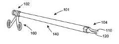
- FIG. 1is a side view of a proximal end of a device for grasping and/or severing according to the invention
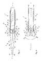
- FIG. 2is a partially cross-sectional, side view of a distal end of the device of FIG. 1 in a closed configuration
- FIG. 3is a partially cross-sectional, plan view from above of the distal end of the device of FIG. 1 in the closed configuration;
- FIG. 4is a partially cross-sectional, side view of the distal end of the device of FIG. 1 in an open grasping configuration
- FIG. 5is a partially cross-sectional, plan view from above of the distal end of the device of FIG. 1 in an open severing configuration
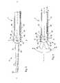
- FIG. 6is a plan view from above of an operative element of the device of FIG. 1 ;
- FIG. 7is a side view of the operative element of FIG. 6 ;
- FIG. 8is an end view of the operative element of FIG. 6 ;
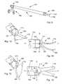
- FIG. 9is a perspective view of another device for grasping and/or severing according to the invention.
- FIG. 10is an enlarged, perspective view of a distal end of the device of FIG. 9 in an open grasping configuration
- FIG. 11is a plan view from above of the distal end of the device of FIG. 9 in the open grasping configuration
- FIG. 12is an enlarged, perspective view of the distal end of the device of FIG. 9 in an open severing configuration
- FIG. 13is a side view of the distal end of the device of FIG. 9 in the open severing configuration.
- the device 1comprises a proximal end 2 , an intermediate portion 3 , and a distal end 4 .
- a first blade element 10 and a second blade 20extend from the intermediate portion of the device 1 at the distal end 4 .
- User operating means 60are provided near the proximal end 2 .
- the intermediate portion 3 of the devicecomprises an actuating means and a housing 40 .
- the blade elements 10 , 20are elongated and comprise distal tips 32 , 42 , cutting edges 30 , 40 , and backs 31 , 41 respectively.
- the blade elements 10 , 20extend from block-shaped support elements 11 , 21 respectively.
- blade elements 10 , 20 and the support elements 11 , 21are substantially similar, for purposes of clarity, similar features of the elements have been indicated by different numerals respectively in the drawings and description.
- the support elements 11 , 21are generally hemispherical in form and comprise external curved surfaces 13 , 23 and substantially flat faces 12 , 22 respectively.
- the support elements 11 , 21are partially cut-away, with a second planar base portion 18 , 28 of each face being arranged at an angle ⁇ to a first planar base portion 17 , 27 thereof ( FIG. 7 ).
- the angle ⁇is less than 180° to enable pivoting of the support elements 11 , 21 to an open grasping configuration ( FIG. 4 ).
- the planar base portions 18 , 28 , 17 , 27are arranged parallel to the Z-axis.
- the support elements 11 , 21are mounted in the device housing 40 so that the element 21 which supports the blade element 20 is inverted relative to the element 11 which supports the blade element 10 .
- the support elements 11 , 21are mounted near the distal end of the housing 40 partially within the housing 40 in a snug fit.
- the blade elements 10 , 20are formed integrally with the front curved portions of the support elements 11 , 21 and extend therefrom in the distal direction.
- the support elements 11 , 21 which are contained within the housing 40are distinct and independent of one another, and are not inter-linked or connected to one another. When mounted in the housing 40 they are held in proximity to each other substantially about a centroid.
- the coupling defined by the support elements 11 , 21is generally spherical in form ( FIG. 2 ).
- the faces 12 , 22 of the two coupled elements 11 , 21are aligned.
- the blade elements 10 , 20 of the device 1substantially abut each other ( FIG. 2 ).
- the support elements 11 , 21are also substantially abutting with the first planar portions 17 , 27 being held in contact ( FIG. 2 ).
- the Y-axis of the device 1is defined as running from the proximal end 2 to the distal end 4 , and is the longitudinal axis of the device 1 .
- the X-axisis taken as running through a centroid of the coupling defined by the support elements 11 , 21 at right angles to the Y-axis ( FIG. 2 ).
- the blade elements 10 , 20 and support elements 11 , 21are movable about two distinct axes. Firstly, they are movable about the X-axis in the directions A, ⁇ A ( FIG. 5 ). Secondly, since the faces 12 and 22 of the support elements 11 , 21 are partially cut-away, the support elements 11 , 21 may be tilted or rotated with respect to each other in directions B, ⁇ B about axes parallel to the Z-axis ( FIG. 4 ). Thus the support elements 11 , 21 and the attached blade elements 10 , 20 are movable about two different axes. The axes about which they are movable intersect substantially at a centroid of the coupled support elements 11 , 21 .
- the coupling defined by the support elements 11 , 21 and the associated housing 40comprise means to facilitate controlled movement of the support elements 11 , 21 relative to the housing 40 .
- the actuating means for moving the blade elements 10 , 20comprises the support elements 11 , 21 arranged to interact with the housing 40 .
- the housing 40comprises three movable sleeves 34 , 35 , 36 , which are connected to the user operating means 60 .
- the sleeves 34 , 35 , 36act as actuating elements to enable a user to control the pivoting of the blade elements 10 , 20 relative to the housing 40 from the proximal end 2 .
- the support elements 11 , 21comprise a series of pins protruding from the curved external surfaces 13 , 23 thereof.
- the support element 11comprises side pins 14 and 15 and a top pin 16 protruding from the top surface thereof.
- the support element 21comprises side pins 24 and 25 and a top pin 26 .
- the pinsco-operate with recesses or slots on the internal surfaces of the sleeves 34 , 35 , 36 .
- the housing 40comprises an outer sleeve 34 , an intermediate sleeve 35 and an inner sleeve 36 .
- the outer sleeve 34has a radius sufficient to accommodate the other sleeves 35 , 36 and the support elements 11 , 21 . As illustrated in FIG. 2 when the device 1 is in the closed configuration, the outer sleeve 34 extends beyond the top pins 16 , 26 and the centroid of the coupled support elements 11 , 21 towards the distal end 4 of the device 1 .
- the sleeves 34 , 35 , 36are substantially cylindrical in form and arranged in a co-axial manner with the intermediate sleeve 35 located within the outer sleeve 34 , and with the inner sleeve 36 located within the intermediate sleeve 35 .
- the sleeves 34 , 35 , 36each comprise arms which extend to the protruding pins of the support elements 11 , 21 .
- the distal end 4 of housing 40has a cylindrical form and surrounds the support elements 11 , 21 .
- the cylindrical formis comprised of the six separate arms extending from the sleeves 34 , 35 , 36 .
- the sleeve 34comprises arms 43 , 44
- the sleeve 35comprises arms 45 , 47
- the sleeve 36comprises arms 46 , 48 .
- the armsare of equal width and are curved in shape.
- the armsare radially staggered around the circumference of the housing 40 so that when aligned in the closed configuration together the arms form a continuation of the cylindrical form of the outer sleeve 34 which extends to the support elements 11 , 21 .
- the arms 43 , 44are a continuation of the sleeve 34 .
- the arms 45 , 47are necessarily arranged at an angle to the intermediate sleeve 35 for purposes of alignment with the outer sleeve 34 and the arms 43 , 44 of the outer sleeve 43 .
- the arms of each individual sleeveare located on opposite sides of the sleeve. Recessed slots for receiving the protruding pins are provided on the internal surfaces of the arms of the sleeves.
- the external sleeve 34comprises recessed slots 51 , 52 for receiving top pins 16 , 26 respectively.
- the intermediate sleeve 35comprises recessed slots (not shown) for receiving pins 14 , 24 respectively
- the inner sleeve 36comprises recessed slots (not shown) for receiving pins 15 , 25 .
- the sleeves 34 , 36are movable in the distal and proximal directions by translation.
- User operating means 60are provided near the proximal end 2 of the device 1 .
- the actuating means of the device 1comprises the sleeves 34 , 35 , 36 , which are moved in response to user operation of the operating means 60 to affect pivoting of the support elements 11 , 21 .
- Movement of the support elements 11 , 21results in the movement of the integral blade elements 10 , 20 in a severing or a grasping action.
- the effect of movement of the sleeves 34 , 35 , 36is to exert forces on the support elements 11 , 21 by means of the pins co-operating with the recesses on the internal surfaces of the sleeves 34 , 35 , 36 .
- the relative positions of the components of the device 1 and their movement relative to each otheris as follows:
- FIGS. 2 and 3are views of the Device at Rest: ( FIGS. 2 and 3 )
- the blade elements 10 , 20are closed and substantially abut each other.
- the first face portions 17 , 27 of the support elements 11 , 21are also substantially abutting and their perimeter edges are aligned.
- the sleeves 34 , 35 and 36are in the rest configuration.
- the outer sleeve 34is moved towards the proximal end 2 of the device 1 relative to the sleeves 35 , 36 , which remain stationary. This has the effect of exerting forces on the top pins 16 , 26 in the proximal direction to pivot the support elements 11 , 21 about grasping pivot axes which are parallel to Z-axis of the device 1 so that the blade elements 10 , 20 are separated in the direction B, ⁇ B.
- the support element 11turns in the direction B pivoting about the pins 14 , 15 and the support element 21 turns in the direction ⁇ B pivoting about the pins 24 , 25 .
- the grasping pivot axis for the support element 11is provided by an axis which extends through the two pins 14 , 15
- the grasping pivot axis for the support element 21is provided by an axis which extends through the two pins 24 , 25 .
- These two pivot axesare parallel, and are spaced-apart by the distance between the side pins 14 , 15 of one support element 11 and the side pins 24 , 25 of the other support element 21 .
- the device 1is thus opened to the open grasping configuration. Movement of the sleeve 34 in the opposite direction results in the blade elements 10 , 20 being closed in a grasping action.
- FIGS. 3 and 5Severing Action
- the inner sleeve 36is moved relative to the intermediate sleeve 35 , and the outer sleeve 34 is held stationary. In the illustrated embodiment, the inner sleeve 36 is moved proximally and the intermediate sleeve 35 is moved distally.
- Thishas the effect of exerting a force on the side pin 14 in the distal direction and a force on the side pin 15 in the proximal direction to pivot the support element 11 in the direction ⁇ A, and has the effect of exerting a force on the side pin 24 in the distal direction and a force on the side pin 25 in the proximal direction to pivot the support element 21 in the direction A in the Y-Z plane of the device 1 pivoting about the X-axis, which acts as the severing pivot axis for both support elements 11 , 21 .
- the support element 11turns in the direction ⁇ A pivoting about the pin 16
- the support element 21turns in the direction A pivoting about the pin 26 .
- the device 1is thus opened to the open severing configuration.
- the severing pivot axis through the X-axisis perpendicular, in this case, to the grasping pivot axes which are parallel to the Z-axis.
- the user operating means 60comprises handles 61 , 63 and a central support 62 .
- the central support 62is attached to the intermediate sleeve 35
- the handle 61is attached to the outer sleeve 34
- the handle 63is attached to the inner sleeve 36 .
- a useroperates the device 1 by means of operating the user operating means 60 to cause movement of the sleeves 34 , 35 , 36 as required.
- the handle 61is operated to move the outer sleeve 34 relative to the other two sleeves 35 , 36 .
- the handle 63 and the central support 62are operated to move the inner sleeve 36 and the intermediate sleeve 35 .
- a user operating means 60comprising handles is used to selectively actuate the actuating means, it will be appreciated that any other suitable arrangement may also be used.
- a surgical device 101comprises a distal end 104 , a proximal end 102 , and a housing 140 .
- First and second blade elements 110 , 120extend from the housing 140 at the distal end 104 of the device 101 .
- User operating means 160are provided near the proximal end 102 .
- the blade elements 110 , 120extend from a coupling defined by support elements 111 , 121 .
- the blade elements 110 , 120 and support elements 111 , 121are movable in two directions in a grasping action and a severing action.
- the housing 140comprises an outer sleeve 134 comprising arms 143 , 144 which extend to the support elements 111 , 121 .
- the arms 143 , 144 of the outer sleeve 134comprise recessed slots for receiving pins protruding from the apexes of the support elements 111 , 121 .
- the inventionprovides a surgical device with the advantage that it may be used for both grasping and severing tissue.
- the actuating means and support means for the bladesare substantially enclosed within the body of the apparatus.
- the grasping and severing actionsare achieved by a actuating mechanism which provides for movement about two different axes. It is not necessary to provide separate actuating means to achieve each distinct movement.
- the actuating meansare contained substantially within or integral with the housing of the device, the device does not present any protruding parts which may move to interfere with the surgical procedure at hand.
- blade elementsis not limited to those illustrated For example, curved blade elements or blade elements of any other suitable form could also be used.
- the coupling of the inventionmay also be used in other suitable applications, for example in gardening tools, shelving support systems and the like.
- Operable elements other than blade elementsmay be provided extending from the support elements.
- the operable elementsmay be corresponding elements which co-operate to perform a particular action.
- Operable elements for any applicationmay be provided for example surgical devices, gardening tools, shelving support systems and the like.
- actuating meanscomprises sleeves substantially of cylindrical form it will be appreciated that any other suitable means may also be used.
Landscapes
- Health & Medical Sciences (AREA)
- Surgery (AREA)
- Life Sciences & Earth Sciences (AREA)
- Medical Informatics (AREA)
- Animal Behavior & Ethology (AREA)
- Engineering & Computer Science (AREA)
- Biomedical Technology (AREA)
- Heart & Thoracic Surgery (AREA)
- Veterinary Medicine (AREA)
- Molecular Biology (AREA)
- Nuclear Medicine, Radiotherapy & Molecular Imaging (AREA)
- General Health & Medical Sciences (AREA)
- Public Health (AREA)
- Ophthalmology & Optometry (AREA)
- Orthopedic Medicine & Surgery (AREA)
- Pathology (AREA)
- Surgical Instruments (AREA)
- Pens And Brushes (AREA)
Abstract
Description
- a first operative element and a second operative element;
- at least one of the operative elements being pivotable about a grasping pivot axis for grasping an object located between the operative elements; and
- at least one of the operative elements being pivotable about a severing pivot axis for severing an object located between the operative elements;
- the grasping pivot axis intersecting the severing pivot axis.
- in the closed configuration, the support element of the first operative element contacting the support element of the second operative element along a first base surface of the support element of the first operative element;
- in the open configuration, the support element of the first operative element contacting the support element of the second operative element along a second base surface of the support element of the first operative element.
- a housing defining a proximal end and a distal end; and
- a first operative element and a second operative element at the distal end of the housing;
- at least one of the operative elements being pivotable relative to the housing about a grasping pivot axis for grasping an object located between the operative elements; and
- at least one of the operative elements being pivotable relative to the housing about a severing pivot axis for severing an object located between the operative elements;
- the housing comprising a first actuating element, a second actuating element and a third actuating element;
- the first actuating element being connected to the operative element, the severing pivot axis being defined by the connection of the first actuating element to the operative element; and
- the second actuating element being connected to the operative element and the third actuating element being connected to the operative element, the grasping pivot axis being defined by the connections of the second actuating element and the third actuating element to the operative element.
- a housing defining a proximal end and a distal end; and
- a first operative element and a second operative element at the distal end of the housing;
- each operative element comprising a support block connected to the housing, and an elongate blade element extending distally from the support block;
- at least one of the blade elements being movable relative to the housing in a grasping action to grasp an object located between the operative elements; and
- at least one of the blade elements being movable relative to the housing in a severing action to sever an object located between the operative elements.
- wherein the first blade element and the second blade element are movable relative to each other in a first direction in a grasping action, and in a second direction in a severing action;
- wherein the first blade element extends from a first support element, and the second blade element extends from a second support element; and
- wherein the support elements are movably coupled, and axes, about which said support elements are movable, intersect substantially at a centroid of a coupling defined by the support elements.
- wherein the operable elements extend from first and second support elements;
- wherein the operable elements are movable relative to each other in a plurality of directions; and
- wherein the support elements are movably coupled, and axes, about which the support elements are movable, intersect substantially at a centroid of a coupling defined by the support elements.
- providing a first operative element and a second operative element;
- providing a first actuating element, a second actuating element and a third actuating element;
- moving the first actuating element relative to the second actuating element and the third actuating element to pivot at least one of the operative elements to grasp an object located between the operative elements; and
- moving the second actuating element relative to the first actuating element in a first direction and moving the third actuating element relative to the first actuating element in a second direction opposite to the first direction to pivot at least one of the operative elements to sever an object located between the operative elements.
Claims (52)
Priority Applications (2)
| Application Number | Priority Date | Filing Date | Title |
|---|---|---|---|
| US12/217,370US20080269790A1 (en) | 2003-06-20 | 2008-07-03 | Device for grasping and/or severing |
| US12/217,369US20090018572A1 (en) | 2003-06-20 | 2008-07-03 | Device for grasping and/or severing |
Applications Claiming Priority (2)
| Application Number | Priority Date | Filing Date | Title |
|---|---|---|---|
| IE20030460 | 2003-06-20 | ||
| IE2003/0460 | 2003-06-20 |
Related Child Applications (2)
| Application Number | Title | Priority Date | Filing Date |
|---|---|---|---|
| US12/217,370ContinuationUS20080269790A1 (en) | 2003-06-20 | 2008-07-03 | Device for grasping and/or severing |
| US12/217,369DivisionUS20090018572A1 (en) | 2003-06-20 | 2008-07-03 | Device for grasping and/or severing |
Publications (2)
| Publication Number | Publication Date |
|---|---|
| US20050021079A1 US20050021079A1 (en) | 2005-01-27 |
| US7410494B2true US7410494B2 (en) | 2008-08-12 |
Family
ID=33524000
Family Applications (3)
| Application Number | Title | Priority Date | Filing Date |
|---|---|---|---|
| US10/870,943Expired - LifetimeUS7410494B2 (en) | 2003-06-20 | 2004-06-21 | Device for grasping and/or severing |
| US12/217,370AbandonedUS20080269790A1 (en) | 2003-06-20 | 2008-07-03 | Device for grasping and/or severing |
| US12/217,369AbandonedUS20090018572A1 (en) | 2003-06-20 | 2008-07-03 | Device for grasping and/or severing |
Family Applications After (2)
| Application Number | Title | Priority Date | Filing Date |
|---|---|---|---|
| US12/217,370AbandonedUS20080269790A1 (en) | 2003-06-20 | 2008-07-03 | Device for grasping and/or severing |
| US12/217,369AbandonedUS20090018572A1 (en) | 2003-06-20 | 2008-07-03 | Device for grasping and/or severing |
Country Status (5)
| Country | Link |
|---|---|
| US (3) | US7410494B2 (en) |
| EP (1) | EP1635717B1 (en) |
| AT (1) | ATE457689T1 (en) |
| DE (1) | DE602004025572D1 (en) |
| WO (1) | WO2004112622A1 (en) |
Cited By (7)
| Publication number | Priority date | Publication date | Assignee | Title |
|---|---|---|---|---|
| US20120109163A1 (en)* | 2004-08-19 | 2012-05-03 | Boston Scientific Scimed, Inc. | Suturing instrument |
| US20140276834A1 (en)* | 2013-03-15 | 2014-09-18 | DePuy Synthes Products, LLC | Methods and devices for removing a spinal disc |
| US20150141992A1 (en)* | 2013-11-19 | 2015-05-21 | Ryan D. Smith | Surgical multi-tool and method of use |
| US20170360465A1 (en)* | 2016-06-21 | 2017-12-21 | Divyze Llc | Surgical multi-tool and method of use |
| US9867658B2 (en)* | 2012-02-20 | 2018-01-16 | Covidien Lp | Knife deployment mechanisms for surgical forceps |
| US10413290B1 (en) | 2013-12-30 | 2019-09-17 | Kearny Quinn Robert, III | Combined needle holder scissors |
| US12167885B2 (en) | 2019-08-16 | 2024-12-17 | Divyze, Inc. | Electrosurgical energy adapter, electrosurgical energy control, and surgical multi-tool |
Families Citing this family (6)
| Publication number | Priority date | Publication date | Assignee | Title |
|---|---|---|---|---|
| DE102007030874B4 (en)* | 2007-06-26 | 2009-04-09 | Aesculap Ag | Surgical instrument |
| US8398673B2 (en)* | 2008-02-15 | 2013-03-19 | Surgical Innovations V.O.F. | Surgical instrument for grasping and cutting tissue |
| WO2012166817A2 (en)* | 2011-05-31 | 2012-12-06 | Intuitive Surgical Operations, Inc. | Surgical instrument with single drive input for two end effector mechanisms |
| DE102012007650A1 (en)* | 2012-04-18 | 2013-10-24 | Karl Storz Gmbh & Co. Kg | Handling device for a medical instrument |
| CN105793498B (en)* | 2014-08-30 | 2018-09-18 | 创新建筑科技公司 | Prefabricated demising wall and headwall |
| JP7113609B2 (en)* | 2017-11-24 | 2022-08-05 | キヤノンファインテックニスカ株式会社 | micro manipulator |
Citations (37)
| Publication number | Priority date | Publication date | Assignee | Title |
|---|---|---|---|---|
| US2278720A (en)* | 1940-04-29 | 1942-04-07 | Standard Screw | Fixture joint |
| DE3322741A1 (en) | 1983-06-24 | 1985-01-03 | Dieter von Dipl.-Ing. 8023 Pullach Zeppelin | Surgical clamping and cutting instrument |
| US4576408A (en)* | 1983-12-15 | 1986-03-18 | Satome Maneki | Chopstick holder |
| US4944093A (en) | 1987-10-26 | 1990-07-31 | Richard Wolf Gmbh | Forceps with shearing jaws |
| US5147373A (en) | 1991-04-29 | 1992-09-15 | Ferzli George S | Laparoscopic instrument |
| US5176702A (en)* | 1991-04-04 | 1993-01-05 | Symbiosis Corporation | Ratchet locking mechanism for surgical instruments |
| US5254129A (en)* | 1991-11-22 | 1993-10-19 | Alexander Chris B | Arthroscopic resector |
| US5254130A (en)* | 1992-04-13 | 1993-10-19 | Raychem Corporation | Surgical device |
| US5275615A (en)* | 1992-09-11 | 1994-01-04 | Anthony Rose | Medical instrument having gripping jaws |
| US5282826A (en) | 1992-03-05 | 1994-02-01 | Quadtello Corporation | Dissector for endoscopic and laparoscopic use |
| WO1994005224A1 (en) | 1992-08-27 | 1994-03-17 | Kensey Nash Corporation | Surgical apparatus |
| US5312391A (en) | 1992-07-29 | 1994-05-17 | Wilk Peter J | Laparoscopic instrument assembly |
| US5342381A (en) | 1993-02-11 | 1994-08-30 | Everest Medical Corporation | Combination bipolar scissors and forceps instrument |
| DE4400409A1 (en) | 1994-01-05 | 1995-07-06 | Hein Kleihues | Microsurgical instrument |
| US5456684A (en) | 1994-09-08 | 1995-10-10 | Hutchinson Technology Incorporated | Multifunctional minimally invasive surgical instrument |
| US5496317A (en) | 1993-05-04 | 1996-03-05 | Gyrus Medical Limited | Laparoscopic surgical instrument |
| US5573535A (en) | 1994-09-23 | 1996-11-12 | United States Surgical Corporation | Bipolar surgical instrument for coagulation and cutting |
| US5613977A (en) | 1992-07-22 | 1997-03-25 | Friatec Ag Keramik-Und-Kunstoffwerke | Gripping and/or cutting instrument for endoscopic purposes |
| US5626595A (en) | 1992-02-14 | 1997-05-06 | Automated Medical Instruments, Inc. | Automated surgical instrument |
| US5782747A (en) | 1996-04-22 | 1998-07-21 | Zimmon Science Corporation | Spring based multi-purpose medical instrument |
| US5893835A (en) | 1997-10-10 | 1999-04-13 | Ethicon Endo-Surgery, Inc. | Ultrasonic clamp coagulator apparatus having dual rotational positioning |
| US5908420A (en) | 1997-10-03 | 1999-06-01 | Everest Medical Corporation | Surgical scissors with bipolar distal electrodes |
| US5984938A (en) | 1989-12-05 | 1999-11-16 | Yoon; Inbae | Surgical instrument with jaws and movable internal scissors and method for use thereof |
| US5984939A (en) | 1989-12-05 | 1999-11-16 | Yoon; Inbae | Multifunctional grasping instrument with cutting member and operating channel for use in endoscopic and non-endoscopic procedures |
| US6017358A (en) | 1997-05-01 | 2000-01-25 | Inbae Yoon | Surgical instrument with multiple rotatably mounted offset end effectors |
| US6024744A (en) | 1997-08-27 | 2000-02-15 | Ethicon, Inc. | Combined bipolar scissor and grasper |
| US20010005787A1 (en)* | 1997-06-27 | 2001-06-28 | Oz Mehmet C. | Method and apparatus for circulatory valve repair |
| US6358268B1 (en) | 2000-03-06 | 2002-03-19 | Robert B. Hunt | Surgical instrument |
| US6391043B1 (en)* | 1997-12-09 | 2002-05-21 | Atropos Limited | Surgical device with same two co-operating elements for gripping and severing |
| US6425896B1 (en) | 1999-07-28 | 2002-07-30 | Forschungszentrum Karlsruhe Gmbh | Endoscopically useable instrument for coagulation by means of high frequency and for the serving of coagulated tissue areas |
| US6506208B2 (en) | 2000-03-06 | 2003-01-14 | Robert B. Hunt | Surgical instrument |
| US20030065358A1 (en)* | 2001-08-06 | 2003-04-03 | Frecker Mary I. | Multifunctional tool and method for minimally invasive surgery |
| US6589231B1 (en) | 1998-11-17 | 2003-07-08 | Scimed Life Systems, Inc. | Multi-function surgical instrument tool actuator assembly |
| US6773434B2 (en) | 2001-09-18 | 2004-08-10 | Ethicon, Inc. | Combination bipolar forceps and scissors instrument |
| US6814745B2 (en) | 2001-01-18 | 2004-11-09 | Richard Wolf Gmbh | Surgical instrument with adjustable tool for gripping, holding or cutting body tissue or the like |
| US6976992B2 (en) | 2002-07-16 | 2005-12-20 | Suturecut, Llc | Dual-function medical instrument |
| US7087070B2 (en) | 2000-07-05 | 2006-08-08 | Bernard Flipo | Multipurpose clamp for medical use comprising two articulated jaws |
Family Cites Families (34)
| Publication number | Priority date | Publication date | Assignee | Title |
|---|---|---|---|---|
| US4655216A (en)* | 1985-07-23 | 1987-04-07 | Alfred Tischer | Combination instrument for laparoscopical tube sterilization |
| US5318221A (en)* | 1989-05-26 | 1994-06-07 | United States Surgical Corporation | Apparatus and method for placing staples in laparoscopic or endoscopic procedures |
| US5665100A (en)* | 1989-12-05 | 1997-09-09 | Yoon; Inbae | Multifunctional instrument with interchangeable operating units for performing endoscopic procedures |
| US5797958A (en)* | 1989-12-05 | 1998-08-25 | Yoon; Inbae | Endoscopic grasping instrument with scissors |
| US5797939A (en)* | 1989-12-05 | 1998-08-25 | Yoon; Inbae | Endoscopic scissors with longitudinal operating channel |
| US5893863A (en)* | 1989-12-05 | 1999-04-13 | Yoon; Inbae | Surgical instrument with jaws and movable internal hook member for use thereof |
| US5171257A (en)* | 1991-04-29 | 1992-12-15 | Ferzli George S | Laparoscopic instrument |
| US5478351A (en)* | 1992-06-24 | 1995-12-26 | Microsurge, Inc. | Endoscopic surgical tool with handle and detachable tool assembly |
| US5403312A (en)* | 1993-07-22 | 1995-04-04 | Ethicon, Inc. | Electrosurgical hemostatic device |
| US5807393A (en)* | 1992-12-22 | 1998-09-15 | Ethicon Endo-Surgery, Inc. | Surgical tissue treating device with locking mechanism |
| US5827323A (en)* | 1993-07-21 | 1998-10-27 | Charles H. Klieman | Surgical instrument for endoscopic and general surgery |
| US5456695A (en)* | 1993-10-25 | 1995-10-10 | United States Surgical Corporation | Multi-tool surgical apparatus |
| DE4341736A1 (en)* | 1993-12-08 | 1995-06-14 | Aesculap Ag | Surgical tubular shaft instrument |
| US5609601A (en)* | 1994-09-23 | 1997-03-11 | United States Surgical Corporation | Endoscopic surgical apparatus with rotation lock |
| US5820009A (en)* | 1996-02-20 | 1998-10-13 | Richard-Allan Medical Industries, Inc. | Articulated surgical instrument with improved jaw closure mechanism |
| US5626608A (en)* | 1996-03-29 | 1997-05-06 | United States Surgical Corporation | Surgical instrument having locking handle |
| US5735849A (en)* | 1996-11-07 | 1998-04-07 | Everest Medical Corporation | Endoscopic forceps with thumb-slide lock release mechanism |
| DE19836481C1 (en)* | 1998-08-12 | 2000-03-30 | Storz Karl Gmbh & Co Kg | Handle for a medical instrument |
| DE19926555A1 (en)* | 1999-06-11 | 2000-12-28 | Storz Karl Gmbh & Co Kg | Medical gripping instrument and method for using this gripping instrument |
| US6117158A (en)* | 1999-07-07 | 2000-09-12 | Ethicon Endo-Surgery, Inc. | Ratchet release mechanism for hand held instruments |
| US6685724B1 (en)* | 1999-08-24 | 2004-02-03 | The Penn State Research Foundation | Laparoscopic surgical instrument and method |
| US6325811B1 (en)* | 1999-10-05 | 2001-12-04 | Ethicon Endo-Surgery, Inc. | Blades with functional balance asymmetries for use with ultrasonic surgical instruments |
| US7090673B2 (en)* | 2001-04-06 | 2006-08-15 | Sherwood Services Ag | Vessel sealer and divider |
| US6755338B2 (en)* | 2001-08-29 | 2004-06-29 | Cerebral Vascular Applications, Inc. | Medical instrument |
| US6602252B2 (en)* | 2002-01-03 | 2003-08-05 | Starion Instruments Corporation | Combined dissecting, cauterizing, and stapling device |
| US7150749B2 (en)* | 2003-06-13 | 2006-12-19 | Sherwood Services Ag | Vessel sealer and divider having elongated knife stroke and safety cutting mechanism |
| US20050143774A1 (en)* | 2003-10-21 | 2005-06-30 | Polo Oscar R. | Laparoscopic needle manipulator |
| US7232440B2 (en)* | 2003-11-17 | 2007-06-19 | Sherwood Services Ag | Bipolar forceps having monopolar extension |
| US7857183B2 (en)* | 2004-07-28 | 2010-12-28 | Ethicon Endo-Surgery, Inc. | Surgical instrument incorporating an electrically actuated articulation mechanism |
| US20060025812A1 (en)* | 2004-07-28 | 2006-02-02 | Ethicon Endo-Surgery, Inc. | Surgical instrument incorporating an electrically actuated pivoting articulation mechanism |
| US7384421B2 (en)* | 2004-10-06 | 2008-06-10 | Sherwood Services Ag | Slide-activated cutting assembly |
| US7559450B2 (en)* | 2005-02-18 | 2009-07-14 | Ethicon Endo-Surgery, Inc. | Surgical instrument incorporating a fluid transfer controlled articulation mechanism |
| US20070027468A1 (en)* | 2005-08-01 | 2007-02-01 | Wales Kenneth S | Surgical instrument with an articulating shaft locking mechanism |
| US7722607B2 (en)* | 2005-09-30 | 2010-05-25 | Covidien Ag | In-line vessel sealer and divider |
- 2004
- 2004-06-21EPEP04740221Apatent/EP1635717B1/ennot_activeExpired - Lifetime
- 2004-06-21WOPCT/EP2004/006802patent/WO2004112622A1/enactiveApplication Filing
- 2004-06-21USUS10/870,943patent/US7410494B2/ennot_activeExpired - Lifetime
- 2004-06-21ATAT04740221Tpatent/ATE457689T1/ennot_activeIP Right Cessation
- 2004-06-21DEDE602004025572Tpatent/DE602004025572D1/ennot_activeExpired - Lifetime
- 2008
- 2008-07-03USUS12/217,370patent/US20080269790A1/ennot_activeAbandoned
- 2008-07-03USUS12/217,369patent/US20090018572A1/ennot_activeAbandoned
Patent Citations (40)
| Publication number | Priority date | Publication date | Assignee | Title |
|---|---|---|---|---|
| US2278720A (en)* | 1940-04-29 | 1942-04-07 | Standard Screw | Fixture joint |
| DE3322741A1 (en) | 1983-06-24 | 1985-01-03 | Dieter von Dipl.-Ing. 8023 Pullach Zeppelin | Surgical clamping and cutting instrument |
| US4576408A (en)* | 1983-12-15 | 1986-03-18 | Satome Maneki | Chopstick holder |
| US4944093A (en) | 1987-10-26 | 1990-07-31 | Richard Wolf Gmbh | Forceps with shearing jaws |
| US5984939A (en) | 1989-12-05 | 1999-11-16 | Yoon; Inbae | Multifunctional grasping instrument with cutting member and operating channel for use in endoscopic and non-endoscopic procedures |
| US5984938A (en) | 1989-12-05 | 1999-11-16 | Yoon; Inbae | Surgical instrument with jaws and movable internal scissors and method for use thereof |
| US5176702A (en)* | 1991-04-04 | 1993-01-05 | Symbiosis Corporation | Ratchet locking mechanism for surgical instruments |
| US5147373A (en) | 1991-04-29 | 1992-09-15 | Ferzli George S | Laparoscopic instrument |
| US5254129A (en)* | 1991-11-22 | 1993-10-19 | Alexander Chris B | Arthroscopic resector |
| US5626595A (en) | 1992-02-14 | 1997-05-06 | Automated Medical Instruments, Inc. | Automated surgical instrument |
| US5282826A (en) | 1992-03-05 | 1994-02-01 | Quadtello Corporation | Dissector for endoscopic and laparoscopic use |
| US5254130A (en)* | 1992-04-13 | 1993-10-19 | Raychem Corporation | Surgical device |
| US5613977A (en) | 1992-07-22 | 1997-03-25 | Friatec Ag Keramik-Und-Kunstoffwerke | Gripping and/or cutting instrument for endoscopic purposes |
| US5312391A (en) | 1992-07-29 | 1994-05-17 | Wilk Peter J | Laparoscopic instrument assembly |
| WO1994005224A1 (en) | 1992-08-27 | 1994-03-17 | Kensey Nash Corporation | Surgical apparatus |
| US5275615A (en)* | 1992-09-11 | 1994-01-04 | Anthony Rose | Medical instrument having gripping jaws |
| US5342381A (en) | 1993-02-11 | 1994-08-30 | Everest Medical Corporation | Combination bipolar scissors and forceps instrument |
| US5496317A (en) | 1993-05-04 | 1996-03-05 | Gyrus Medical Limited | Laparoscopic surgical instrument |
| US5797936A (en) | 1994-01-05 | 1998-08-25 | Kleihues; Hein | Microsurgical instrument |
| DE4400409A1 (en) | 1994-01-05 | 1995-07-06 | Hein Kleihues | Microsurgical instrument |
| US5456684A (en) | 1994-09-08 | 1995-10-10 | Hutchinson Technology Incorporated | Multifunctional minimally invasive surgical instrument |
| US5573535A (en) | 1994-09-23 | 1996-11-12 | United States Surgical Corporation | Bipolar surgical instrument for coagulation and cutting |
| US5782747A (en) | 1996-04-22 | 1998-07-21 | Zimmon Science Corporation | Spring based multi-purpose medical instrument |
| US6017358A (en) | 1997-05-01 | 2000-01-25 | Inbae Yoon | Surgical instrument with multiple rotatably mounted offset end effectors |
| US6214028B1 (en) | 1997-05-01 | 2001-04-10 | Inbae Yoon | Surgical instrument with multiple rotatably mounted offset end effectors and method of using the same |
| US20010005787A1 (en)* | 1997-06-27 | 2001-06-28 | Oz Mehmet C. | Method and apparatus for circulatory valve repair |
| US6024744A (en) | 1997-08-27 | 2000-02-15 | Ethicon, Inc. | Combined bipolar scissor and grasper |
| US5908420A (en) | 1997-10-03 | 1999-06-01 | Everest Medical Corporation | Surgical scissors with bipolar distal electrodes |
| US5893835A (en) | 1997-10-10 | 1999-04-13 | Ethicon Endo-Surgery, Inc. | Ultrasonic clamp coagulator apparatus having dual rotational positioning |
| US6391043B1 (en)* | 1997-12-09 | 2002-05-21 | Atropos Limited | Surgical device with same two co-operating elements for gripping and severing |
| US6589231B1 (en) | 1998-11-17 | 2003-07-08 | Scimed Life Systems, Inc. | Multi-function surgical instrument tool actuator assembly |
| US6425896B1 (en) | 1999-07-28 | 2002-07-30 | Forschungszentrum Karlsruhe Gmbh | Endoscopically useable instrument for coagulation by means of high frequency and for the serving of coagulated tissue areas |
| US6506208B2 (en) | 2000-03-06 | 2003-01-14 | Robert B. Hunt | Surgical instrument |
| US6358268B1 (en) | 2000-03-06 | 2002-03-19 | Robert B. Hunt | Surgical instrument |
| US7087070B2 (en) | 2000-07-05 | 2006-08-08 | Bernard Flipo | Multipurpose clamp for medical use comprising two articulated jaws |
| US6814745B2 (en) | 2001-01-18 | 2004-11-09 | Richard Wolf Gmbh | Surgical instrument with adjustable tool for gripping, holding or cutting body tissue or the like |
| US20030065358A1 (en)* | 2001-08-06 | 2003-04-03 | Frecker Mary I. | Multifunctional tool and method for minimally invasive surgery |
| US7208005B2 (en) | 2001-08-06 | 2007-04-24 | The Penn State Research Foundation | Multifunctional tool and method for minimally invasive surgery |
| US6773434B2 (en) | 2001-09-18 | 2004-08-10 | Ethicon, Inc. | Combination bipolar forceps and scissors instrument |
| US6976992B2 (en) | 2002-07-16 | 2005-12-20 | Suturecut, Llc | Dual-function medical instrument |
Cited By (23)
| Publication number | Priority date | Publication date | Assignee | Title |
|---|---|---|---|---|
| US8398660B2 (en)* | 2004-08-19 | 2013-03-19 | Boston Scientific Scimed, Inc. | Suturing instrument |
| US8858574B2 (en) | 2004-08-19 | 2014-10-14 | Boston Scientific Scimed, Inc. | Suturing instrument |
| US20120109163A1 (en)* | 2004-08-19 | 2012-05-03 | Boston Scientific Scimed, Inc. | Suturing instrument |
| US9867658B2 (en)* | 2012-02-20 | 2018-01-16 | Covidien Lp | Knife deployment mechanisms for surgical forceps |
| US10639094B2 (en) | 2012-02-20 | 2020-05-05 | Covidien Lp | Knife deployment mechanisms for surgical forceps |
| US20140276834A1 (en)* | 2013-03-15 | 2014-09-18 | DePuy Synthes Products, LLC | Methods and devices for removing a spinal disc |
| US10080572B2 (en)* | 2013-03-15 | 2018-09-25 | DePuy Synthes Products, Inc. | Methods and devices for removing a spinal disc |
| US9314254B2 (en)* | 2013-03-15 | 2016-04-19 | DePuy Synthes Products, Inc. | Methods and devices for removing a spinal disc |
| US20160199200A1 (en)* | 2013-03-15 | 2016-07-14 | DePuy Synthes Products, Inc. | Methods and devices for removing a spinal disc |
| US9050101B1 (en)* | 2013-11-19 | 2015-06-09 | Ryan D. Smith | Surgical multi-tool and method of use |
| AU2014353067B2 (en)* | 2013-11-19 | 2019-07-18 | Divyze, Inc. | Surgical multi-tool and method of use |
| US11857246B2 (en) | 2013-11-19 | 2024-01-02 | Divyze, Inc. | Surgical multi-tool and method of use |
| US9393066B2 (en)* | 2013-11-19 | 2016-07-19 | Ryan D. Smith | Surgical multi-tool and method of use |
| US9931155B2 (en)* | 2013-11-19 | 2018-04-03 | Divyze, Inc. | Surgical multi-tool and method of use |
| US11020168B2 (en) | 2013-11-19 | 2021-06-01 | Divyze, Inc. | Surgical multi-tool and method of use |
| US20150327911A1 (en)* | 2013-11-19 | 2015-11-19 | Ryan D. Smith | Surgical multi-tool and method of use |
| US20170128125A1 (en)* | 2013-11-19 | 2017-05-11 | Ryan D. Smith | Surgical multi-tool and method of use |
| US20150141992A1 (en)* | 2013-11-19 | 2015-05-21 | Ryan D. Smith | Surgical multi-tool and method of use |
| US10413290B1 (en) | 2013-12-30 | 2019-09-17 | Kearny Quinn Robert, III | Combined needle holder scissors |
| US10792065B2 (en) | 2016-06-21 | 2020-10-06 | Divyze, Inc. | Surgical multi-tool and method of use |
| US9943327B2 (en)* | 2016-06-21 | 2018-04-17 | Divyze, Inc. | Surgical multi-tool and method of use |
| US20170360465A1 (en)* | 2016-06-21 | 2017-12-21 | Divyze Llc | Surgical multi-tool and method of use |
| US12167885B2 (en) | 2019-08-16 | 2024-12-17 | Divyze, Inc. | Electrosurgical energy adapter, electrosurgical energy control, and surgical multi-tool |
Also Published As
| Publication number | Publication date |
|---|---|
| EP1635717B1 (en) | 2010-02-17 |
| US20090018572A1 (en) | 2009-01-15 |
| DE602004025572D1 (en) | 2010-04-01 |
| EP1635717A1 (en) | 2006-03-22 |
| US20080269790A1 (en) | 2008-10-30 |
| WO2004112622A1 (en) | 2004-12-29 |
| US20050021079A1 (en) | 2005-01-27 |
| ATE457689T1 (en) | 2010-03-15 |
Similar Documents
| Publication | Publication Date | Title |
|---|---|---|
| US20080269790A1 (en) | Device for grasping and/or severing | |
| EP0507621B1 (en) | Thumb-activated actuating member for endoscopic surgical instrument | |
| CA2106243C (en) | Articulating endoscopic surgical apparatus | |
| EP0623316B1 (en) | Laparoscopic surgical instrument | |
| US7105005B2 (en) | Arteriotomy scissors for minimally invasive surgical procedures | |
| US5171258A (en) | Double acting, dual pivot disposable laparoscopic surgical instruments | |
| US4674501A (en) | Surgical instrument | |
| US5156633A (en) | Maryland dissector laparoscopic instrument | |
| JP3676385B2 (en) | Surgical instrument for endoscopy | |
| US5241968A (en) | Single acting endoscopic instruments | |
| KR102210194B1 (en) | Apparatus for tissue cutting and sealing | |
| EP0684014A1 (en) | Surgical instrument | |
| EP0507622B1 (en) | Endoscopic surgical instruments | |
| US6364891B1 (en) | Back biting surgical instrument | |
| JP2001057981A (en) | Bent laparoscope scissors having arc portion with two kinds of curvatures | |
| WO1998026723A1 (en) | Dual pin and groove pivot for micro-instrument | |
| JP2004525725A (en) | Surgical cutting instrument | |
| US20220071690A1 (en) | Electrosurgical forceps for grasping, treating, and/or dividing tissue | |
| EP3636189B1 (en) | Electrosurgical forceps | |
| US20220331004A1 (en) | Electrosurgical forceps | |
| IE20040420A1 (en) | A device for grasping and/or severing | |
| US20220249118A1 (en) | Surgical slicing shears | |
| US5849021A (en) | Elongated thumb loop for surgical instrument | |
| WO1992017115A1 (en) | Clevis for endoscopic surgical instrument | |
| JPH0586223B2 (en) |
Legal Events
| Date | Code | Title | Description |
|---|---|---|---|
| AS | Assignment | Owner name:SURGICAL INNOVATIONS V.O.F., NETHERLANDS Free format text:ASSIGNMENT OF ASSIGNORS INTEREST;ASSIGNORS:KALMANN, MENNO;MOLL, FRANCISCUS LAURENS;REEL/FRAME:015499/0463 Effective date:20040608 | |
| AS | Assignment | Owner name:INTERVENTIONAL & SURGICAL INNOVATIONS, LLC, NEW YO Free format text:ASSIGNMENT OF ASSIGNORS INTEREST;ASSIGNOR:SURGICAL INNOVATIONS V.O.F.;REEL/FRAME:019659/0474 Effective date:20070706 | |
| STCF | Information on status: patent grant | Free format text:PATENTED CASE | |
| AS | Assignment | Owner name:SURGICAL INNOVATIONS V.O.F.,NETHERLANDS Free format text:ASSIGNMENT OF ASSIGNORS INTEREST;ASSIGNOR:INTERVENTIONAL & SURGICAL INNOVATIONS, LLC;REEL/FRAME:024278/0114 Effective date:20100209 | |
| FPAY | Fee payment | Year of fee payment:4 | |
| AS | Assignment | Owner name:TAKE5 ENDOTECH, NETHERLANDS Free format text:ASSIGNMENT OF ASSIGNORS INTEREST;ASSIGNOR:SURGICAL INNOVATIONS V.O.F.;REEL/FRAME:029863/0098 Effective date:20130219 | |
| FPAY | Fee payment | Year of fee payment:8 | |
| FEPP | Fee payment procedure | Free format text:11.5 YR SURCHARGE- LATE PMT W/IN 6 MO, SMALL ENTITY (ORIGINAL EVENT CODE: M2556); ENTITY STATUS OF PATENT OWNER: SMALL ENTITY | |
| MAFP | Maintenance fee payment | Free format text:PAYMENT OF MAINTENANCE FEE, 12TH YR, SMALL ENTITY (ORIGINAL EVENT CODE: M2553); ENTITY STATUS OF PATENT OWNER: SMALL ENTITY Year of fee payment:12 |