US7410338B2 - Exoskeleton for the human arm, in particular for space applications - Google Patents
Exoskeleton for the human arm, in particular for space applicationsDownload PDFInfo
- Publication number
- US7410338B2 US7410338B2US10/443,111US44311103AUS7410338B2US 7410338 B2US7410338 B2US 7410338B2US 44311103 AUS44311103 AUS 44311103AUS 7410338 B2US7410338 B2US 7410338B2
- Authority
- US
- United States
- Prior art keywords
- exoskeleton
- joints
- joint
- arm
- shoulder
- Prior art date
- Legal status (The legal status is an assumption and is not a legal conclusion. Google has not performed a legal analysis and makes no representation as to the accuracy of the status listed.)
- Expired - Fee Related
Links
- 210000002435tendonAnatomy0.000claimsabstractdescription92
- 230000033001locomotionEffects0.000claimsabstractdescription76
- 210000000707wristAnatomy0.000claimsabstractdescription54
- 210000001503jointAnatomy0.000claimsdescription102
- 210000000245forearmAnatomy0.000claimsdescription15
- 210000002310elbow jointAnatomy0.000claimsdescription4
- 239000004744fabricSubstances0.000claimsdescription4
- 210000000323shoulder jointAnatomy0.000claimsdescription3
- 210000003857wrist jointAnatomy0.000claimsdescription2
- 230000037431insertionEffects0.000claims1
- 238000003780insertionMethods0.000claims1
- 230000007246mechanismEffects0.000description23
- 210000000038chestAnatomy0.000description8
- 238000010586diagramMethods0.000description8
- 230000006835compressionEffects0.000description6
- 238000007906compressionMethods0.000description6
- 210000003414extremityAnatomy0.000description6
- 230000006870functionEffects0.000description6
- 230000005540biological transmissionEffects0.000description5
- 238000012549trainingMethods0.000description5
- 210000004247handAnatomy0.000description4
- 238000012986modificationMethods0.000description4
- 230000004048modificationEffects0.000description4
- 230000008901benefitEffects0.000description3
- 238000013461designMethods0.000description3
- 210000003811fingerAnatomy0.000description3
- 230000035807sensationEffects0.000description3
- 239000007787solidSubstances0.000description3
- 238000013459approachMethods0.000description2
- 210000000988bone and boneAnatomy0.000description2
- 238000004891communicationMethods0.000description2
- 238000005516engineering processMethods0.000description2
- 210000002758humerusAnatomy0.000description2
- 238000007654immersionMethods0.000description2
- 239000000463materialSubstances0.000description2
- 238000005259measurementMethods0.000description2
- 238000000034methodMethods0.000description2
- 239000004033plasticSubstances0.000description2
- 229920003023plasticPolymers0.000description2
- 229920000915polyvinyl chloridePolymers0.000description2
- 239000004800polyvinyl chlorideSubstances0.000description2
- 210000003813thumbAnatomy0.000description2
- 241000238421ArthropodaSpecies0.000description1
- 229920000049Carbon (fiber)Polymers0.000description1
- 229920002101ChitinPolymers0.000description1
- 241000282412HomoSpecies0.000description1
- 241001465754MetazoaSpecies0.000description1
- 206010028289Muscle atrophyDiseases0.000description1
- 239000000956alloySubstances0.000description1
- 229910045601alloyInorganic materials0.000description1
- 229910052782aluminiumInorganic materials0.000description1
- XAGFODPZIPBFFR-UHFFFAOYSA-NaluminiumChemical compound[Al]XAGFODPZIPBFFR-UHFFFAOYSA-N0.000description1
- 239000004917carbon fiberSubstances0.000description1
- 239000002131composite materialSubstances0.000description1
- 230000008878couplingEffects0.000description1
- 238000010168coupling processMethods0.000description1
- 238000005859coupling reactionMethods0.000description1
- 238000005202decontaminationMethods0.000description1
- 230000003588decontaminative effectEffects0.000description1
- 230000007812deficiencyEffects0.000description1
- 238000007689inspectionMethods0.000description1
- 230000003993interactionEffects0.000description1
- 238000012423maintenanceMethods0.000description1
- 229910052751metalInorganic materials0.000description1
- 239000002184metalSubstances0.000description1
- VNWKTOKETHGBQD-UHFFFAOYSA-NmethaneChemical compoundCVNWKTOKETHGBQD-UHFFFAOYSA-N0.000description1
- 230000005486microgravityEffects0.000description1
- 230000003387muscularEffects0.000description1
- 201000000585muscular atrophyDiseases0.000description1
- 210000005036nerveAnatomy0.000description1
- 230000000149penetrating effectEffects0.000description1
- 238000000554physical therapyMethods0.000description1
- 230000008439repair processEffects0.000description1
- 238000004904shorteningMethods0.000description1
- 229920002379silicone rubberPolymers0.000description1
- 239000004945silicone rubberSubstances0.000description1
- 210000001562sternumAnatomy0.000description1
- 238000012546transferMethods0.000description1
Images


Classifications
- A—HUMAN NECESSITIES
- A61—MEDICAL OR VETERINARY SCIENCE; HYGIENE
- A61H—PHYSICAL THERAPY APPARATUS, e.g. DEVICES FOR LOCATING OR STIMULATING REFLEX POINTS IN THE BODY; ARTIFICIAL RESPIRATION; MASSAGE; BATHING DEVICES FOR SPECIAL THERAPEUTIC OR HYGIENIC PURPOSES OR SPECIFIC PARTS OF THE BODY
- A61H1/00—Apparatus for passive exercising; Vibrating apparatus; Chiropractic devices, e.g. body impacting devices, external devices for briefly extending or aligning unbroken bones
- A61H1/02—Stretching or bending or torsioning apparatus for exercising
- A61H1/0274—Stretching or bending or torsioning apparatus for exercising for the upper limbs
- A61H1/0277—Elbow
- A—HUMAN NECESSITIES
- A61—MEDICAL OR VETERINARY SCIENCE; HYGIENE
- A61H—PHYSICAL THERAPY APPARATUS, e.g. DEVICES FOR LOCATING OR STIMULATING REFLEX POINTS IN THE BODY; ARTIFICIAL RESPIRATION; MASSAGE; BATHING DEVICES FOR SPECIAL THERAPEUTIC OR HYGIENIC PURPOSES OR SPECIFIC PARTS OF THE BODY
- A61H1/00—Apparatus for passive exercising; Vibrating apparatus; Chiropractic devices, e.g. body impacting devices, external devices for briefly extending or aligning unbroken bones
- A61H1/02—Stretching or bending or torsioning apparatus for exercising
- A61H1/0274—Stretching or bending or torsioning apparatus for exercising for the upper limbs
- A61H1/0281—Shoulder
- A—HUMAN NECESSITIES
- A63—SPORTS; GAMES; AMUSEMENTS
- A63B—APPARATUS FOR PHYSICAL TRAINING, GYMNASTICS, SWIMMING, CLIMBING, OR FENCING; BALL GAMES; TRAINING EQUIPMENT
- A63B21/00—Exercising apparatus for developing or strengthening the muscles or joints of the body by working against a counterforce, with or without measuring devices
- A63B21/00178—Exercising apparatus for developing or strengthening the muscles or joints of the body by working against a counterforce, with or without measuring devices for active exercising, the apparatus being also usable for passive exercising
- A—HUMAN NECESSITIES
- A63—SPORTS; GAMES; AMUSEMENTS
- A63B—APPARATUS FOR PHYSICAL TRAINING, GYMNASTICS, SWIMMING, CLIMBING, OR FENCING; BALL GAMES; TRAINING EQUIPMENT
- A63B21/00—Exercising apparatus for developing or strengthening the muscles or joints of the body by working against a counterforce, with or without measuring devices
- A63B21/00181—Exercising apparatus for developing or strengthening the muscles or joints of the body by working against a counterforce, with or without measuring devices comprising additional means assisting the user to overcome part of the resisting force, i.e. assisted-active exercising
- A—HUMAN NECESSITIES
- A63—SPORTS; GAMES; AMUSEMENTS
- A63B—APPARATUS FOR PHYSICAL TRAINING, GYMNASTICS, SWIMMING, CLIMBING, OR FENCING; BALL GAMES; TRAINING EQUIPMENT
- A63B21/00—Exercising apparatus for developing or strengthening the muscles or joints of the body by working against a counterforce, with or without measuring devices
- A63B21/40—Interfaces with the user related to strength training; Details thereof
- A63B21/4001—Arrangements for attaching the exercising apparatus to the user's body, e.g. belts, shoes or gloves specially adapted therefor
- A63B21/4017—Arrangements for attaching the exercising apparatus to the user's body, e.g. belts, shoes or gloves specially adapted therefor to the upper limbs
- A63B21/4019—Arrangements for attaching the exercising apparatus to the user's body, e.g. belts, shoes or gloves specially adapted therefor to the upper limbs to the hand
- A—HUMAN NECESSITIES
- A63—SPORTS; GAMES; AMUSEMENTS
- A63B—APPARATUS FOR PHYSICAL TRAINING, GYMNASTICS, SWIMMING, CLIMBING, OR FENCING; BALL GAMES; TRAINING EQUIPMENT
- A63B21/00—Exercising apparatus for developing or strengthening the muscles or joints of the body by working against a counterforce, with or without measuring devices
- A63B21/40—Interfaces with the user related to strength training; Details thereof
- A63B21/4001—Arrangements for attaching the exercising apparatus to the user's body, e.g. belts, shoes or gloves specially adapted therefor
- A63B21/4017—Arrangements for attaching the exercising apparatus to the user's body, e.g. belts, shoes or gloves specially adapted therefor to the upper limbs
- A63B21/4021—Arrangements for attaching the exercising apparatus to the user's body, e.g. belts, shoes or gloves specially adapted therefor to the upper limbs to the wrist
- A—HUMAN NECESSITIES
- A63—SPORTS; GAMES; AMUSEMENTS
- A63B—APPARATUS FOR PHYSICAL TRAINING, GYMNASTICS, SWIMMING, CLIMBING, OR FENCING; BALL GAMES; TRAINING EQUIPMENT
- A63B21/00—Exercising apparatus for developing or strengthening the muscles or joints of the body by working against a counterforce, with or without measuring devices
- A63B21/40—Interfaces with the user related to strength training; Details thereof
- A63B21/4023—Interfaces with the user related to strength training; Details thereof the user operating the resistance directly, without additional interface
- A63B21/4025—Resistance devices worn on the user's body
- A—HUMAN NECESSITIES
- A63—SPORTS; GAMES; AMUSEMENTS
- A63B—APPARATUS FOR PHYSICAL TRAINING, GYMNASTICS, SWIMMING, CLIMBING, OR FENCING; BALL GAMES; TRAINING EQUIPMENT
- A63B21/00—Exercising apparatus for developing or strengthening the muscles or joints of the body by working against a counterforce, with or without measuring devices
- A63B21/40—Interfaces with the user related to strength training; Details thereof
- A63B21/4041—Interfaces with the user related to strength training; Details thereof characterised by the movements of the interface
- A63B21/4047—Pivoting movement
- A—HUMAN NECESSITIES
- A63—SPORTS; GAMES; AMUSEMENTS
- A63B—APPARATUS FOR PHYSICAL TRAINING, GYMNASTICS, SWIMMING, CLIMBING, OR FENCING; BALL GAMES; TRAINING EQUIPMENT
- A63B23/00—Exercising apparatus specially adapted for particular parts of the body
- A63B23/035—Exercising apparatus specially adapted for particular parts of the body for limbs, i.e. upper or lower limbs, e.g. simultaneously
- A63B23/03508—For a single arm or leg
- A—HUMAN NECESSITIES
- A63—SPORTS; GAMES; AMUSEMENTS
- A63B—APPARATUS FOR PHYSICAL TRAINING, GYMNASTICS, SWIMMING, CLIMBING, OR FENCING; BALL GAMES; TRAINING EQUIPMENT
- A63B23/00—Exercising apparatus specially adapted for particular parts of the body
- A63B23/035—Exercising apparatus specially adapted for particular parts of the body for limbs, i.e. upper or lower limbs, e.g. simultaneously
- A63B23/12—Exercising apparatus specially adapted for particular parts of the body for limbs, i.e. upper or lower limbs, e.g. simultaneously for upper limbs or related muscles, e.g. chest, upper back or shoulder muscles
- A63B23/1209—Involving a bending of elbow and shoulder joints simultaneously
- A—HUMAN NECESSITIES
- A63—SPORTS; GAMES; AMUSEMENTS
- A63B—APPARATUS FOR PHYSICAL TRAINING, GYMNASTICS, SWIMMING, CLIMBING, OR FENCING; BALL GAMES; TRAINING EQUIPMENT
- A63B23/00—Exercising apparatus specially adapted for particular parts of the body
- A63B23/035—Exercising apparatus specially adapted for particular parts of the body for limbs, i.e. upper or lower limbs, e.g. simultaneously
- A63B23/12—Exercising apparatus specially adapted for particular parts of the body for limbs, i.e. upper or lower limbs, e.g. simultaneously for upper limbs or related muscles, e.g. chest, upper back or shoulder muscles
- A63B23/1245—Primarily by articulating the shoulder joint
- A63B23/1263—Rotation about an axis passing through both shoulders, e.g. cross-country skiing-type arm movements
- B—PERFORMING OPERATIONS; TRANSPORTING
- B25—HAND TOOLS; PORTABLE POWER-DRIVEN TOOLS; MANIPULATORS
- B25J—MANIPULATORS; CHAMBERS PROVIDED WITH MANIPULATION DEVICES
- B25J9/00—Programme-controlled manipulators
- B25J9/0006—Exoskeletons, i.e. resembling a human figure
- A—HUMAN NECESSITIES
- A63—SPORTS; GAMES; AMUSEMENTS
- A63B—APPARATUS FOR PHYSICAL TRAINING, GYMNASTICS, SWIMMING, CLIMBING, OR FENCING; BALL GAMES; TRAINING EQUIPMENT
- A63B2208/00—Characteristics or parameters related to the user or player
- A63B2208/12—Characteristics or parameters related to the user or player specially adapted for children
Definitions
- the inventionrelates to an exoskeleton for the human arm.
- exoskeletonwas originally used in biology for designating the outer supporting shell of an animal.
- arthropodshave an outer shell of chitin instead of an internal skeleton.
- the termhas also been associated with structural devices designed to be attached around the limbs of people.
- the text belowrelates to the preferred application of the invention, specifically to its application to space technologies. Still more precisely, consideration is given to remotely controlling a humanoid type robot working outside a space station, for example the international space station.
- the robotcould be the robot known as “Eurobot” which is intended to provide highly accurate and dextrous means for performing inspection, maintenance, and repair actions on equipment in the highly hostile environment of space.
- Eurobotthe robot known as “Eurobot” which is intended to provide highly accurate and dextrous means for performing inspection, maintenance, and repair actions on equipment in the highly hostile environment of space.
- the robotis fitted with three moving arms similar to human arms (i.e. in particular having seven degrees of freedom). Most of the time, the robot is programmed to perform pre-established tasks, but in some circumstances the robot needs to be remotely controlled:
- the need to perform very precise manipulationsmakes it necessary to use so-called “immersion” techniques.
- the operatorwears video goggles, force feedback gloves, and one or more arm exoskeletons so as to be able to feel the same sensations as the robot, i.e. the sensations which the operator would feel when performing the tasks that are being executed by the robot.
- Exoskeletons in the state of the artgenerally suffer from various drawbacks and/or insufficiencies, such as the following:
- human arm exoskeletonsneed to overcome a major problem, namely that of imitating the movements of the complex human joints that are constituted by the shoulder, the elbow, and the wrist. Imitation is difficult because these joints are closely covered, with their axes of rotation moving with changing posture of the arm.
- exoskeletonshave attempted to deal with the problem of the shoulder by implementing a mechanism that rests on the human shoulder from above and behind. The imperfections of that approach can be found in the bulk and the weight of the mechanism. It also weighs down the arm. Similarly massive solutions have also been used for the wrist.
- U.S. Pat. No. 4,575,297 A(Hans Richter) describes a robot having a chest plate, an upper arm member, and a lower arm member having finger and thumb units into which the human limbs are inserted.
- a human operator to whom the robot members are attachedsits on a support structure such as a moving chair.
- the robot members, their lengths, the joints between them, and the joint axescorrespond to those of the human operator.
- Each jointis associated with a hydraulic motor sensor device.
- the shoulder portion of the robotis restricted to movements about two axes. Another axis allows the elbow to flexed or to be extended.
- An axis parallel to the axis of the forearmallows the forearm to turn.
- a knuckle joint parallel to the swivel joint of the elbowprovides means to enable the wrist to move in human manner.
- exoskeleton mechanism taught by the above-specified patentcopies the normal movements of a human arm.
- Each actuated jointis controlled by hydraulic actuators, which are directly mounted beside the joints.
- the range of possible movementsis relatively limited. In particular movement without backlash is not possible.
- U.S. Pat. No. 5,967,580 A(Mark E. Rosheim) relates to a pair of connected-together joints and to force-generator means for using them in slave robot systems.
- the patentrelates to an anthropomorphic mechanical manipulator providing some of the capabilities of a human torso and it can move in ways similar to the chest, the shoulder, the arm, the wrist, and the hands of a human.
- the moving structure of the robot described in the above-specified patentresembles the moving structure of a human arm. It follows that it is desired to provide a mechanical manipulator resembling the upper human torso and the arm, and capable of being provided with movement options substantially equivalent to those available to the upper arm and torso of a human.
- a mechanical structureprovides means for engaging the hands of an operator.
- a counterpart mechanismcan be used as an exoskeleton for controlling the slave robot, but it is not optimized for that use per se. It is possible to provide force feedback only in the portion of the exoskeleton that is equivalent to the hand.
- the two mechanismsare equivalent to the upper structure of a human limb in terms of movement (parameters of the limbs and the joints). Each axis of rotation is directly controlled by direct current (DC) linear motors. Only a very limited range of normal human movements of the arm can be covered with the exoskeleton mechanism as described. As mentioned above, force feedback is possible only for the human hand, with this characteristic being the main object of the patent.
- U.S. Pat. No. 6,301,526 A(mun Sang Kim et al.) relates mainly to a device having a force feedback function and which is mounted on a human arm. This can return feedback information concerning operating limits by using motor brakes.
- the main deviceis a series type chain configuration fixed on the back of an operator.
- Second and third combining meansare fixed above and below the elbow, and fourth combining means are fixed to a back portion of the hand.
- Seven axes of the exoskeletoninclude electric brake units for generating torque.
- Position-determining units and gear units for amplifying torqueare associated with the actuator units.
- the base of the moving systemis fixed to the operator's back and not to the chest.
- the movement of the exoskeletoncan be influenced only by passive electric brakes, which can be used only to damp the natural movements of the human arm.
- Movementsare restricted to only five degrees of freedom. Movements of the shoulder girdle, and movements of the wrist are neither detectable nor controllable. Each axis is actuated directly by a DC motor device, which is mounted close to an appropriate joint axis. Because of its highly simplified moving structure, many of the components need to be designed to be adjustable. The base of the exoskeleton is fixed on the upper portion of the operator's back.
- the inventionseeks simultaneously to mitigate the drawbacks of prior art devices, some of which are outlined above, and to satisfy the needs that have been felt, and which are also summarized above.
- An object of the inventionis to provide an exoskeleton for the human arm presenting, in particular, all of its degrees of freedom, which is lightweight, portable since it does not limit the movements of the operator, fittable to a large percentage of the population without significant modification, capable of sensing all of the movements of the human arm, not limiting on the range of natural movements, and comfortable.
- the support base of the arm exoskeleton of the inventionresembles half of the top of a suit of armor. It has two rigid chest plates (front and back) and a hinged sleeve. The chest plates are fixed to the operator's torso by straps or any suitable equivalent means.
- the front plateserves as a structural base for a system of joints to which the sleeve is joined. It provides a fixed reference for all movements of the exoskeleton.
- the back platecarries motors that move the joints of the sleeve. The motors are connected to the joints by a series of flexible tendons which actuate them.
- the exoskeleton of the inventionpresents several advantageous technical characteristics.
- the movements specific to an exoskeleton of the inventionare designed in a special manner. There is no attempt to imitate the movements of the shoulder, of the elbow, and/or of the wrist of a human.
- an alternative moving systemproviding the same freedom of movement is placed in parallel with the human joints. This system and the human joints form a closed dynamic loop which:
- each posture of the human jointscan be determined unambiguously by the corresponding posture of the moving system of the exoskeleton.
- the base of the exoskeletonis a portion of the human body. Consequently, the exoskeleton can be designed as a portable system which provides more flexibility for the general movements of the operator.
- a portable exoskeleton controllerBy using a portable exoskeleton controller, remote control in weightlessness, or at least in microgravity, is greatly simplified since no resultant force on the body of the operator can cause a movement that moves the operator away from the control station.
- force feedback joystickswere used, they would create forces against the body of the astronaut, pushing the astronaut away from the joystick. Consequently, the astronaut needs to be attached in a suitable location, thereby restricting the operations the astronaut can perform.
- a second important characteristicsrelates to the fact that all of the actuated joints in the exoskeleton (i.e. its non-passive joints) are controlled by cable tendon transmissions.
- electrical control membersdirectly mounted on the exoskeleton. Those dispositions make the exoskeleton bulky, heavy, and require a large number of control units in order to remain compatible with high weight.
- the use of cable tendons in the inventionmakes it possible to place the control unit on the back plate of the exoskeleton. The weight of the control members is thus carried by the torso. The result obtained is an arm that is extremely lightweight and can be controlled by smaller control members.
- a third important characteristicrelates to the ability of the exoskeleton of the invention to be fitted to different humans. Because of its specific structural characteristics, as described below, the master arm can be fitted to practically any human subject (the above-mentioned percentile range). The adjustments required for adapting the exoskeleton can be performed while it is being worn and are typically restricted to tightening two screws or equivalent members, as also described below.
- the inventionthus mainly provides an arm exoskeleton for acquiring data representative of the movements of the arm joints of a human operator by means of measurement sensors and for feeding back forces and/or torques to joints of the arm exoskeleton by means of actuation units associated with at least some of said operator arm joints, the exoskeleton comprising a first device in the form of a sleeve for wearing on at least one arm of an operator so as to form a moving system of exoskeleton joints disposed parallel to said arm joints, said device comprising a first subassembly or “shoulder exoskeleton” comprising a first determined number of joints associated with the shoulder joints of said operator, a second subassembly or “elbow exoskeleton” comprising a second determined number of joints associated with the elbow joints of said operator, and a third subassembly or “wrist exoskeleton” comprising a third determined number of joints associated with the wrist joints of said operator, wherein said actuation units are controlled by flexible tendons
- the inventionalso provides the use of an arm exoskeleton for remotely controlling a robot of humanoid type working outside a space station, the robot being provided with artificial arms and performing tasks under the control of a human operator, said arm exoskeleton being worn on at least one of the operator's arms, said robot receiving data causing it to execute movements unambiguously related to the movements of the arm and transmitting feedback data forcing all or some of said joints of said arm exoskeleton to execute movements, thereby giving rise to corresponding movements of the arm.
- FIGS. 1A and 1Bare diagrams showing an embodiment of an arm exoskeleton of the invention worn by an operator, seen respectively from in front and from behind;
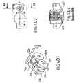
- FIG. 2is an exploded view showing the three main subassemblies of an exoskeleton of a preferred embodiment of the invention, namely the wrist subassembly, the elbow subassembly, and the shoulder subassembly, respectively;
- FIG. 3Ais a more detailed diagram showing the palm of the wrist subassembly of the FIG. 2 exoskeleton, while being worn on the hand of an operator;
- FIG. 3Bis a diagram in three dimensions showing the various joints associated with the wrist subassembly of the FIG. 3A exoskeleton together with their axes of rotation;
- FIGS. 3 C 1 to 3 C 3show a first member of the wrist subassembly of the FIG. 3A exoskeleton, respectively in three dimensions, in side view, and in section on C/C of FIG. 3 C 2 ;
- FIGS. 3 D 1 to 3 D 3show a first member of the wrist subassembly of the FIG. 3A exoskeleton respectively in three dimensions, in plan view, and in section on H/H of FIG. 3 D 2 ;
- FIGS. 3 E 1 to 3 E 3show a third member of the wrist subassembly of the FIG. 3A exoskeleton, respectively in three dimensions, in side view, and in section on L/L of FIG. 3 E 2 ;
- FIGS. 3 F 1 to 3 F 3show a fourth member of the wrist subassembly of the FIG. 3A exoskeleton, respectively in three dimensions, in plan view, and in section on R/R of FIG. 3 F 2 ;
- FIGS. 3 G 1 to 3 G 3show a fifth member of the wrist subassembly of the FIG. 3A exoskeleton, respectively in three dimensions, in side view, and in section on U/U of FIG. 3 G 2 ;
- FIGS. 3 H 1 to 3 H 3show a sixth member of the wrist subassembly of the FIG. 3A exoskeleton, respectively in three dimensions, in front view, and in section on Q/Q of FIG. 3 H 2 ;
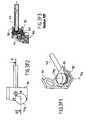
- FIG. 4Ashows in greater detail the elbow subassembly of the FIG. 2 exoskeleton, in three dimensions seen from the outside and in front, worn on the arm of an operator and attached to the elbow, the forearm extending vertically upwards;
- FIG. 4Bis a diagrammatic three-dimensional view showing the various joints associated with the elbow subassembly of the FIG. 4A exoskeleton, together with their axes of rotation:
- FIGS. 4 C 1 and 4 C 2are more detailed views, respectively a side view and a plan view, showing the bundle of tendons and the pre-tensioning or “pre-loading” unit of the elbow subassembly of FIGS. 4A and 4B ;
- FIGS. 4 D 1 to 4 D 3are more detailed views showing the members of one of the joints of the elbow subassembly of the exoskeleton of FIGS. 4A and 4B , respectively in a three-dimensional three-quarter view, in plan view, and in section on M/M of FIG. 4 D 2 ;
- FIGS. 5A and 5Bare more detailed views showing the shoulder subassembly of the FIG. 2 exoskeleton worn on the arm of an operator and attached to the shoulder, in three-quarter views respectively from in front and from above;
- FIG. 5Cis a diagrammatic three-dimensional view showing the various joints associated with the shoulder subassembly of the exoskeleton of FIGS. 5A and 5B , together with their axes of rotation;
- FIG. 5Dis a back view of the tendon pre-tensioning mechanism associated with the shoulder subassembly of the exoskeleton of FIGS. 5A and 5B ;
- FIGS. 5 E 1 to 5 E 3are more detailed views showing a first member of the shoulder subassembly of the exoskeleton of FIGS. 5A to 5D , respectively in three dimensions, in plan view, and in section on D/D of FIG. 5 E 2 ;
- FIGS. 5 F 1 to 5 F 4are more detailed views showing a second member of the shoulder subassembly of the exoskeleton of FIGS. 5A to 5D , constituted by a telescopic joint shown respectively in the long state as an end view and as a side view partially in section, and in the short state, as an end view and as a side view partially in section;
- FIG. 5 F 5shows a detail of the telescopic joint of FIGS. 5 F 1 to 5 F 4 :
- FIGS. 5 G 1 to 5 G 3are more detailed views showing a third member of the shoulder subassembly of the exoskeleton of FIGS. 5A to 5D , respectively in three dimensions, in plan view, and in section on A/A of FIG. 5 G 2 ;
- FIGS. 5 H 1 and 5 H 2are more detailed views showing a third member of the shoulder subassembly of the exoskeleton of FIGS. 5A to 5D , which subassembly includes an inflatable cushion, the views being respectively a three-dimensional view and a section view on B/B;
- FIGS. 6A to 6Care diagrams showing the mechanism for actuating the joints of the exoskeleton of the invention by means of cable tendons;
- FIG. 6Dis a diagram showing the mechanism for actuating the telescopic joint of FIGS. 5 F 1 to 5 F 5 ;
- FIGS. 7A and 7Bare sagittal section views of the inflatable cushion members for fixing to the upper arm and to the forearm, respectively.
- the “go” datais constituted by orders transmitted to the robot in order to actuate it as a function of the particular movements that the operator imparts to the exoskeleton.
- the robotreproduces the movements of the exoskeleton.
- the robotsends “feedback” data enabling the operator physically to “feel” the forces and torques to which the robot is subjected, instead of being restricted to perceiving them only “visually”, e.g. by following the tasks performed by the robot on a display screen.
- This feedback on the operatoris most important since it makes it possible, for example, to enable the remotely-controlled robot to exert only the precisely-required amounts of force or torque.
- FIGS. 1A to 7BA practical example of an arm exoskeleton in a preferred embodiment of the invention is described below with reference to FIGS. 1A to 7B .
- elements that are identicalare given the same references and are described again only where necessary.
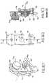
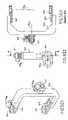
- FIGS. 1A and 1Bare diagrams showing an example of an arm exoskeleton EXB constituting a preferred embodiment of the invention and showing its main components.
- the arm exoskeleton EXBis shown being worn by an operator U, seen in front view ( FIG. 1A ) and in fragmentary back view ( FIG. 1B ).
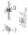
- the arm exoskeleton proper EXBcomprises three main subassemblies: a wrist subassembly 1 ; an elbow subassembly 2 ; and a shoulder subassembly 3 , respectively.
- These three subassemblies 1 to 3are dedicated to detecting relative movements of a wrist P, an elbow C, and a shoulder E of operator U, and to actuating the associated joints. They form a sleeve which is worn on one of the operator's arms, for example a right arm Bd.
- FIGS. 1A and 1Bthe subassemblies 1 to 3 of the arm exoskeleton EXB are shown as being worn on the right arm Bd of the operator U since it is assumed that the operator is right-handed.
- the device of the inventionis not limited in any way to this characteristic. It can equally well be worn on a left arm Bg of operator U, or on both arms, without thereby going beyond the ambit of the invention.
- the three subassemblies 1 to 3form a moving system having specific characteristics that are described below. This system is shown in greater detail in an exploded view in FIG. 2 .
- the above-mentioned moving systemand more precisely its wrist subassembly 1 , is fixed to a glove 5 worn on one of the hands M of the operator, in this case the right hand.
- the operatorcould wear such gloves on both hands.
- the above-mentioned dynamic moving systemis fixed more precisely by means of its shoulder subassembly 3 to a torso TH of the operator U by means of a support base 4 .
- the support base 4resembles half of a piece of a suit of armor. It comprises two rigid plates: a front or “chest” plate 40 ( FIG. 1A ) and a rear or “back” plate 41 ( FIG. 1B ).
- the rigid plates 40 and 41are fixed to the torso TH of the operator U by straps 42 , or by any appropriate equivalent means.
- the front plate 40serves as the structural base for the system of joints constituting the subassemblies 1 to 3 . It provides a fixed reference for all movements of the arm exoskeleton EXB.
- the various subassemblies 1 to 3 of the above-specified moving systemare connected together by bundles of flexible tendons 7 of the cable type for actuating particular joints associated with the subassemblies 1 to 3 , which joints are said to be “active” and are actuated in turn by motors Mt ( FIG. 1B ).
- the flexible tendonsare constituted by two distinct types of element; cables proper and spiral-type sheaths guiding the cables over the major part of their lengths.
- the visible portions of the bundles 7are constituted essentially by the sheaths.
- a first bundlegoes from the back of the operator U to a pre-loading unit in the shoulder subassembly 3 , and then from there along the structure of an initial loading unit of the elbow subassembly, and then from there to the wrist P.
- the second bundlegoes directly from the back to the joints prior to penetrating in a pre-loading unit at the base of the exoskeleton EXB.
- jointsIn contrast, other joints, referred to as “passive” joints, cannot exert any force or torque on the human arm Bd, but can nevertheless be associated with movement sensors, thus making it possible for the movements of the human arm Bd of the operator U, optionally to be detected and transmitted in the form of corresponding movement data.
- sensors referenced Ca 12 to Ca 16 , Ca 21 to Ca 32 , Ca 31 to Ca 36 , 218 and 226are shown in various figures accompanying the present description.
- the back plate 41carries the above-mentioned motors Mt. As shown in FIG. 1B , it is assumed that the motors Mt (not shown explicitly) are housed inside a pack 6 fixed to the plate 41 . Advantageously, DC motors are used.
- the pack 6is connected in particular to the moving system, and more particularly to the shoulder subassembly 3 , by means of the bundle of tendons 7 .
- the motorsalso include transceiver circuits for data and instructions communicating with the robot that is to be remotely controlled, either directly or else via an intermediate station (not shown).
- the motors Mtactuate one or more joints of the subassemblies 1 to 3 by acting on the corresponding flexible tendons of the bundle 7 in the manner described below.
- the moving systemis described in greater detail below.
- the master arm of the exoskeleton EXBcomprises sixteen joints, and therefore has sixteen degrees of freedom or “DOF”.
- Each axisis fitted with an angle sensor in order to pick up information concerning joint angles (i.e. turning movements about particular axes).
- FIG. 2is an exploded view of these three mechanisms 1 to 3 interconnected by a bundle of flexible tendons 7 .
- the master armis not designed to imitate the arrangement of human joints, but instead to connect with them by means of an alternative moving system of joints disposed over the human limb: i.e. the arm Bd in the example described.
- Each of these three subassemblies 1 to 3thus represent an alternative structure for the wrist P, the elbow C, and the shoulder E (see FIG. 1A ).
- the three subassemblies 1 to 3 of the moving system of the arm exoskeleton EXBare described below in greater detail. For ease of understanding, the description begins with the shoulder subassembly 3 .
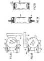
- FIGS. 5A and 5Bshow the shoulder subassembly 3 respectively as a front view and in top three-quarter view. In these figures, the head of the operator U is not shown and the bundle of flexible tendons 7 is shown as being cut. Reference is also made to detail FIGS. 5 E 1 to 5 H 2 .
- the subassembly 3includes six joint axes, five of a rotory or “rotoid” type, and one of a sliding or “prismatic” type.
- FIG. 5Cis an isometric view showing, in three dimensions, the relative positions of these six axes which are referenced ⁇ 31 to ⁇ 36 , for a particular posture of the shoulder E of the operator U at a given instant.
- the corresponding jointsare referred to as “joint 31 ” to “joint 36 ”.
- the subassembly 3is designed to perform the same movements as a human shoulder E, even though the five DOF of the human shoulder E are simulated by a mechanism having six DOF.
- the movement of the exoskeleton shoulder 3is not limited, either in amplitude or in dexterity.
- the base of the shoulder exoskeleton 3constitutes the complete base of the serial linkage of the arm exoskeleton EXB, and it is secured to the rigid chest plate 40 which is secured to the torso TH of the operator U by means of straps 42 .
- the connectionis provided via a fixing piece which serves as a parent link for the first joint of the exoskeleton EXB.
- the distal end of the subassembly 3is situated at the base of the top portion of an arm BS of the operator U where it is fixed by means of an inflatable cushion 30 , itself surrounded by a rigid annular piece 31 .
- the first and second joints having respective axes ⁇ 31 and ⁇ 32are active joints and they are actuated by respective flexible tendons 731 ′ and 732 ′ forming part of the bundle of tendons 7 .
- each of these jointsis actuated by a pair of tendons, thus enabling it to move either clockwise or counterclockwise.
- the first joint about the axis ⁇ 31is a rotary joint and is actuated by two tendons 731 ′ forming part of above-mentioned “bundle No. 2”.
- This jointcombines the fixing piece 38 with the first member of a link 31 ′.
- the link 31 ′which is the child link of the first joint, comprises a pulley 312 (best seen in FIG. 5 E 3 ) which is fixed to a rotary shaft 313 which is connected via ball bearings to the fixing piece 38 .
- the shaft 313is also rigidly connected to a circular plate 314 which is screwed under two side walls 315 and 316 (best seen in FIG.
- the first jointwhich is another rotary joint turning about the axis ⁇ 32 , connects the link 31 ′ to the child link of the second joint, referred to as link 31 ′.
- This linkhas another shaft 322 which is constrained to rotate with the side walls 315 and 316 .
- the pair of tendons 732 ′(guided by spiral-type sheaths 732 ) passes through a pre-loading unit 320 and is fixed to the pulley 323 .
- Two side walls 324 and 325are screwed together to a telescopic connection 326 .
- the shaft 322is centered in a middle zone of the side walls by means of ball bearings enabling the link 31 ′ to rotate completely about the shaft 322 and thus about the common axis ⁇ 32 .
- the pulley 323is rigidly fixed to the side walls and thus moves the link 32 ′ relative to the link when the tendons 732 ′ pull or push.
- the joint 33 of sliding type along axis ⁇ 33is provided with a telescopic tube F ( FIG. 6D ) extended by a pre-tensioning spring SP.
- the spring SPis of the coil spring type.
- a tendon 733 ′ running through sheath 733 and attached to the end of the tube and running along the tubeenables the telescopic tube to retract by contracting the spring. Prior to passing through the telescope, the tendon 733 ′ passes through the pre-loading unit 320 .
- a fixed link of the telescopic joint 33is constituted by a first telescopic tube 332 (FIG. 5 F 2 ) and is combined with telescopic connection 326 (FIG. 5 E 1 .
- a moving link 33 ′comprises a telescopic tube system F and distal ends of a telescopic connection 333 which are secured to an intermediate piece 335 .
- the distal telescopic connection 333is pre-loaded against the telescopic connection 326 . If the tendon 733 ′ opposes the force of the spring SP, it causes the telescopic tubes to contract along the common axis ⁇ 33 .
- the joint 34which is a passive joint of rotary type, joins the link 33 ′ with the link 34 ′.
- the joint 34enables the link 34 ′ to turn about the axis ⁇ 34 .
- the link 34 ′comprises a shaft 341 which is connected by radial ball bearings to intermediate piece 335 enabling rotation about the axis ⁇ 34 .
- the axis ⁇ 34is secured to a U-shaped piece 342 which carries two additional plates 343 and 345 at its two distal ends. These plates contain ball bearings for turning about the axis ⁇ 35 , and they are associated with respective top plates 344 and 346 .
- the fifth joint 35which is also a passive rotary joint, connects link 34 ′ with link 35 ′ while allowing turning about the axis ⁇ 35 .
- the linkhas two pieces colinear with the axes of the shafts 351 and 354 which are fixed on an outer ring 353 by means of fixing plates.
- the fixing plate 352fixes the shaft 351 to the outer ring 353
- the fixing plate 355fixes the shaft 354 to the bottom of the ring 353 .
- the two shaftspass through ball bearings which are held respectively between the additional plate 343 and the top plate 344 , and between the additional plate 345 and the top plate 346 .
- the joint 36 of axis ⁇ 36is an active joint, and it is used for imparting torque to the top portion of the arm BS.
- a pair of tendons 736 ′ coming from the back of the operator Upass through the outer ring 353 without touching it and are attached to an inner ring 362 which acts as a hollow pulley.
- the inner ring 362which is a member of link 36 ′, is attached to another circular ring 31 which carries inflatable cushions 30 .
- the circular ring 31is connected to the outer ring 353 by means of small section ball bearings, enabling rotation to take place about the axis ⁇ 36 .
- the connection ring 363is screwed to the ring 31 and another member of the link 36 ′.
- the three joints 34 to 36have their axes ⁇ 34 to ⁇ 36 intersecting at a single point, thus enabling them together to act as a simple spherical joint at the distal end of the subassembly 3 .
- FIG. 5Dis an isometric back view showing the system 8 (device 80 ) for pre-tensioning the tendons of the bundle 7 in three dimensions.
- the tendonswhich are guided inside sheaths, can be pre-tensioned so as to put the outer sheath under compression.
- FIG. 6Cshows in greater detail the general configuration of such a pre-loading unit 8 .
- Each pre-loading unit in the design of the exoskeleton EXBcomprises similar devices.
- a rigid structureestablishes a rigid reference and is referred to herein as CR, said structure being used for receiving screws C 1 for pre-loading the tendons. These screws C 1 are hollow and the tendons pass through them, which tendons are arbitrarily referenced 700 ′.
- a sheath 700which guides each tendon 700 ′, is intersected at the point where the pre-loading unit is located, and the intersecting ends 700 a of the sheaths terminate at the outside surfaces of the pre-loading screws C 1 .
- sheath 700Since the distal ends of sheaths 700 are stopped at points close to the actuation unit at 700 b I and close to the motor unit at a point 700 b II, the sheath 700 is compressed as soon as the pre-loading screws C 1 are turned clockwise. This increased compression in the spiral sheaths 700 surrounding the tendons 700 ′ tensions the tendons. The tendons 700 are threaded along the sheaths which means that the tendons 700 are pre-loaded.
- the five DOF of the human arm and the six DOF of the shoulder exoskeleton subassembly 3form a moving closed loop having the following properties:
- elbow subassembly 2is described below in greater detail with reference to FIGS. 4 A to 4 D 3 .
- FIG. 4Ais more precisely a view of the elbow subassembly 2 seen from in front. It has four joint axes.
- FIG. 4Bis an isometric view showing the relative positions of the four axes ⁇ 21 to ⁇ 24 in three dimensions when the elbow C of the operator U is in a particular posture at a given instant.
- the corresponding jointsare referenced joint 21 to joint 24 .
- twin telescopic tubes 200 and 202respectively which are adjustable in length, providing the means for adjusting the length of the exoskeleton to fit the human upper arm BS. Length can be adjusted by means of two screw members 201 and 203 respectively for each of the tubes 200 and 202 . No other adjustment is needed.
- the first ends of the telescopic tubes 200 and 202are secured to an annular piece 204 surrounding the upper arm BS, i.e. the arm above the elbow. When the exoskeleton EXB is assembled, this annular piece is secured rigidly to the ring 363 of the shoulder subassembly 3 . The second ends are secured to the piece 205 which is horseshoe-shaped, also surrounding the upper arm BS.
- the side base plate 206is rigidly mounted to the ring 205 and carries the shaft 207 which establishes a portion of the common joint 21 .
- the middle base plate 208is also connected to the proximal side of the ring 205 and carries another shaft 209 which co-operates with the shaft 207 to constitute the mechanical means enabling the joint 21 to turn about the axis ⁇ 21 .
- This configurationis best seen in FIG. 4 C 2 .
- the joint adjustment unitconstitutes the parent link for the joint 21 .
- the child link of this joint, link 21 ′has another ring 210 of horseshoe shape.
- a side plate 212is secured on its distal side to the proximal side of the ring 210 .
- the side plate 212On its proximal side, the side plate 212 is mounted on the shaft 207 by means of ball bearings which permit turning movement.
- a pulley 213is fixed to the side plate 212 to actuate the link 21 ′ about the axis ⁇ 21 of the joint 21 .
- the tendons 721 ′which come from the cable bundle 7 pass through the side base plate 206 and are fixed to the pulley 213 .
- the middle plate 214is also fixed to the proximal side of the ring 210 .
- the proximal side of the middle plate 214is mounted by means of ball bearings to the shaft 209 which is colinear with the shaft 207 , enabling the link 21 ′ to turn about the axis ⁇ 21 .
- Two hollow tubes 215 and 216are attached to the distal side of the ring 210 . These tubes serve as a parent link for the common sliding joint 22 .
- the pre-loading unit of the forearm 217is fixed to these hollow tubes 215 and 216 by means of screws.
- tendons 219pass through the pre-loading unit 217 , however, the bundle of cables 7 is not shown.
- FIGS. 4 C 1 and 4 C 2show the incoming tendons of the bundle of cables 7 entering the pre-loading unit 217 , while the outgoing tendons are not shown.
- the link 21 ′ and the link 22 ′together form joint 22 which is a passive, sliding joint.
- the link 22 ′comprises two solid rods 221 and 222 which are colinear and concentric with the hollow tubes 215 and 216 so as to fit exactly in the bores of the hollow tubes, thus forming a telescopic tube system.
- the solid rods 221 and 222are free to move inside the hollow tubes 215 and 216 .
- the rods 221 and 222are attached to a piece 220 which constitutes a segment of a ring.
- This piece 220has its proximal side connected to the two hollow tubes and its distal side attached to a T-shaped piece 224 which carries a small shaft 225 .
- the link 22 ′can move linearly along the axis ⁇ 22 relative to the link 21 ′.
- the pre-loading unitcarries a linear sensor 218 whose moving portion is fixed to a plate 223 .
- This plateis fixed to the solid rods 221 and 222 by means of screws.
- the link 22 ′which is a moving link in the joint 22 , is simultaneously the parent link for the joint 23 .
- FIGS. 4 D 1 and 4 D 3show the members of the joint 23 in greater detail, respectively in three dimensions, and in section M/M of FIG. 4 D 2 .
- the T-shaped piece 224carries a fixed shaft 225 having two ball bearings 226 and 227 mounted thereon; the bearings being mounted respectively on the side and middle portions respectively of the T-shaped piece 224 .
- the moving link on joint 23is the link 23 ′ which can turn passively about the axis ⁇ 23 of the joint 23 .
- This linkhas an outer metal ring 230 which is connected to a connection piece 231 via its bottom.
- This connection piece 231is screwed between two side plates: a middle plate 232 and a side plate 233 respectively. These side plates 233 and 232 are connected to the outsides of the ball bearings 227 and 226 respectively and can thus turn about the shaft 225 .
- the child link 24 ′ of the joint 24which is a moving part, comprises a rigid ring 240 which contains an inflatable cushion 28 , and a hollow pulley 241 which is attached to the proximal side of the rigid ring 240 .
- the tendons 724 ′which are guided along the sheaths 724 pass through the outer ring 230 and are fixed to the hollow pulley 241 (as can be seen in FIGS. 3 H 1 to 3 H 3 ).
- the rigid ring 240is centered inside the outer ring 230 by means of a ball bearing 242 of small section, enabling the ring 240 to turn about the axis ⁇ 24 inside the outer ring 230 . This turning is driven by relative movement of the tendons 724 ′.
- tendons 724 ′are connected to the pulley 241 and to the sheaths 724 which are mechanically locked outside the outer ring 230 , by means of stop pieces 234 .
- the link 24 ′can be turned about the axis ⁇ 24 of the joint 24 , thereby causing the forearm AB of the operator U to perform pronation or supination.
- the human elbow joint Ccannot be considered as being a pure hinge, insofar as the position of its axis oscillates while it is moving. Consequently, using an exoskeleton having a single common DOF for the purpose of imitating flexing of the elbow cannot lead to results that are accurate and gives rise to friction in the mechanism since the two axes of rotation never coincide.
- joint 22 and joint 23having respective axes ⁇ 22 and ⁇ 23 and fitted with angle sensors (e.g. the linear sensor 218 for axis ⁇ 22 and the angle sensor 226 for axis ⁇ 23 in FIGS. 4 C 1 and 4 C 2 ).
- angle sensorse.g. the linear sensor 218 for axis ⁇ 22 and the angle sensor 226 for axis ⁇ 23 in FIGS. 4 C 1 and 4 C 2 .
- the combined mechanismthen enables accurate results to be obtained for flexing of the elbow C, even though the system departs considerably from the biological model.
- the systemestablishes a moving reference structure over the human elbow C based on the upper arm BS and the end of the forearm AB.
- the human movements of the elbow C(flexion/extension and pronation/supination) can be detected and influenced without constricting the natural range of these movements.
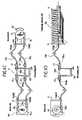
- the wrist subassembly 1is described in greater detail below with reference to FIGS. 3 A to 3 H 3 .
- FIG. 3Ais a view of the palm of the wrist subassembly 1 .
- This subassemblycomprises six joint axes, all of the rotary type.
- FIG. 3Bis an isometric view showing the relative positions of these six axes ⁇ 11 to ⁇ 16 in three dimensions for a particular posture of the hand M and the wrist P of the operator U, at a given instant.
- FIGS. 3A and 3Bare used as a reference for explaining the operation of the first joint of the wrist subassembly 1 .
- FIGS. 3 C 1 to 3 G 3show various other views of the mechanism separately.
- the corresponding jointsare referenced joint 11 to joint 16 .
- the proximal end of the subassembly 1is engaged on the forearm AB and is fixed thereto by an inflatable cushion 28 surrounded by a rigid annular piece 240 that is put on the forearm close to the hand.
- This rigid annular piece 240is connected on its outside to the inside portion of an outer ring 110 by means of a ball bearing 111 of thin section, as can be seen more clearly in FIGS. 3 H 1 to 3 H 3 .
- the outer ring 110can turn about the axis ⁇ 11 which is the axis of rotation of joint 11 .
- FIG. 3Aonly the outer ring 110 and the inflated cushion 28 can be seen.
- the link 11 ′is the child link of the joint 11 , and it comprises the outer ring 110 and stop pieces 112 which are screwed to the ring 110 to constitute means for locking the sheaths 711 at their distal ends.
- the tendons 711 ′are threaded through these stop pieces 112 and through holes in the outer ring 110 at the end of a hollow pulley 113 which is attached to the fixed ring 240 .
- An additional member of the link 11 ′is a fixing connection 114 which is used for fixing a mechanical shaft 115 (best seen in FIGS. 3 C 1 - 3 C 3 ) orthogonally to the outer ring 110 .
- a stop plate 116is fixed beneath the fixing connection 114 to stop the distal ends of the spiral sheaths 712 .
- the joint 12causes the link 12 ′ to move about the link 11 ′ along the axis of rotation ⁇ 12 .
- the section view of the joint 12 shown in FIG. 3 C 3is used for describing the joint in greater detail.
- the shaft 115carries a ball bearing 117 at its distal end, with a base plate 120 being fixed thereto on the outside surface of the bearing.
- This base plate 120constitutes a reference for the link 12 ′, to which all of the other portions of this link are connected.
- the pulley 124is screwed to the base plate 120 , thereby connecting the tendons 712 ′ to the link 12 ′.
- the tendons 712 ′are threaded through the stop piece 116 of the preceding link and establish rotation of the link 12 ′ as soon as relative movement between the tendons 712 ′ and the sheaths 712 is induced by the motors acting on the tendons.
- two horizontal plates 121 and 122are fixed to the base plate 120 by means of screws, as can be seen more particularly in FIGS. 3 D 1 to 3 D 3 .
- These two platescarry respective ball bearings 124 and 123 , and the shaft 131 of the joint 13 is held between them.
- the joint 13connects the link 12 ′ as parent link to the child link 13 ′ which turns passively about the axis ⁇ 13 .
- the base of the link 13 ′is the shaft 131 which has a cylindrical piece 130 fixed thereto.
- This cylindrical piece 130includes a stud orthogonal to its cylindrical surface and providing means for fixing a cylindrical bundle 132 at its proximal end.
- connection plate 133which carries two horizontal plates, a top plate 134 and a bottom plate 135 , as can be seen more particularly in FIGS. 3 E 1 to 3 E 3 .
- the bottom plate 135provides stop means for the distal ends of the sheaths 714 .
- the plates 134 and 135carry ball bearings which hold and center the shaft 141 between the plates 134 and 135 .
- the joint 14is an active joint causing the link 14 ′ to turn about the link 13 ′ along the ax is ⁇ 14 .
- the link 14 ′has another cylindrical portion 140 which is fixed to the shaft 141 and has a stud orthogonal to its cylindrical surface which fixes the proximal end of a second cylindrical bundle 143 .
- a pulley 142is also fixed to the cylindrical portion 140 to secure the tendons 714 ′.
- the distal end of the cylindrical bundle 143is held in another cylindrical portion 144 that is attached to a shaft 145 .
- This shaft 145constitutes the mechanical hinge axis of passive joint 15 which connects link 14 to link 15 and in which link 15 turns as the child link about link 14 along axis ⁇ 15 , as shown more particularly in FIGS. 3 F 1 to 3 F 3 , and in FIG. 3B .
- the shaft 145is held between two ball bearings which are held by two horizontal plates, a top plate 151 and a bottom plate 152 , these plates being screwed to the base plate 150 of the link 15 ′.
- the distal endis fixed on a hard plastics glove 5 on the hand M of the operator U.
- the glove 5is constituted by a main shell 50 having a first orifice 51 (on top in FIG. 3A ) through which the thumb can extend and one or more (axial) orifices 52 allowing the other fingers of the hand M to pass.
- the subassembly 1is fixed to the shell 50 of the glove 5 by any appropriate means (screws, etc.) via a distal piece 54 associated with the axis ⁇ 16 of the joint 16 .
- Joint 16associates link 15 ′ with the distal piece 54 enabling active rotation under the influence of tendons about the axis ⁇ 16 .
- the distal piece 54is fixed to the back of the glove 5 in which the hand M of the operator U is inserted.
- the other side of this distal piece 54is connected to a base plate 160 as can be seen more particularly in FIGS. 3 G 1 to 3 G 3 .
- This base plate 160is held to a second plate 161 to fix a shaft 162 orthogonal to the surfaces of the pieces.
- This shaft 162carries a ball bearing 167 at its distal end, with the base plate 150 of the link 15 ′ being attached thereto.
- a pulley 153which is directly mounted on the base plate 150 fixes the tendons 716 coming from the sheaths 716 . Since the sheaths 716 are fixed at their distal ends to a stop plate 163 , which is attached to the base plate of the link 16 ′, any relative movement of the tendons 716 ′ against the sheaths 716 causes the link 16 ′ to turn about the axis ⁇ 16 relative to the link 15 ′.
- the mobility of the wrist subassemblycan be described as follows:
- the three joints joint 13 to joint 15 of axes ⁇ 13 to ⁇ 15are joints of rotary type.
- the joints 13 and 15 of axes ⁇ 13 and ⁇ 15are purely passive, while the joint 14 of ⁇ 14 is active and controlled by pairs of flexible tendons of the bundle 7 , these tendons being referenced 714 ′.
- the passive jointsare included in the subassembly 1 so as to ensure that the human wrist P can be moved without being hindered during operations of remotely controlling the robot (not shown).
- the mechanismWith the structure of the human skeleton and the attachment points on the body of the human operator U on two sides, the mechanism constitutes a pantograph. Abduction or adduction of the wrist P can be controlled by actuating the joint 14 of axis ⁇ 14 and passive movements then result in the passive joints. If the tendons 714 ′ actuate the joint 14 towards small angles, then abduction is imposed on the joint of the wrist P. When the tendons 714 ′ cause the joint 14 to move towards large angles, then adduction is imposed on the joint of the wrist P.
- the joints 12 and 16 of axes ⁇ 12 and ⁇ 16are both of the active type. They are used for detecting and for imposing flexing movement to the wrist P. For example, if both joints turn clockwise, then the links of the exoskeleton joints cause the human wrist P to flex upwards, and conversely if they are operated in the counterclockwise direction then they impose downward flexing. If both joints are prevented from moving, then the wrist is prevented from flexing.
- the joints 12 and 16are controlled by respective pairs of flexible tendons 712 ′ and 716 ′.
- the joint 11is included in the moving system.
- the joint 11 of axis ⁇ 11is another joint of rotary type and it is active, being capable of compensating the eccentricity in any combined movement. It is controlled by a pair of flexible tendons 711 ′.
- all of the joints of the subassembly 1are associated with respective sensors Ca 12 to Ca 16 ( FIG. 3B ) which measure angles of rotation about the corresponding axes ⁇ 11 to ⁇ 16 .
- the data that results from these measurementsis transmitted by any appropriate means to receiver systems, e.g. located in the space station, or directly in the pack 6 ( FIG. 1B ). This transmission can take place over wires or it can on the contrary be wireless (radio transmission, etc.).
- receiver systemse.g. located in the space station, or directly in the pack 6 ( FIG. 1B ).
- This transmissioncan take place over wires or it can on the contrary be wireless (radio transmission, etc.).
- these aspectsare well known to the person skilled in the art and there is no need to describe them in greater detail herein.
- the subassembly 1allows the wrist P to move freely without in any way restricting the movements of the operator U.
- one of the important characteristics of the inventionis that the torque for driving the active joints is transmitted remotely by using tendon cables 7 guided along the structure of the exoskeleton EXB and coming from motors Mt placed on the back plate 42 for the torso, being transmitted to each of the actuated joints. Installing the motors behind the user U serves to minimize the size and the weight of the exoskeleton master arm EXB.
- the tendons of the bundle 7be constituted by multistrand cables, typically 7 ⁇ 19 cables having a diameter of 1 millimeter (mm). This choice serves to minimize friction in curves and can deliver loads of up to 50 newton-meters (Nm).
- Nmnewton-meters
- the cablesneed to be subjected to forces in such a manner as to be pre-tensioned to half their operating load, i.e. 25 Nm in this example.
- FIGS. 6A , 6 B, and 6 Care diagrams showing how a pair of cable tendons arbitrarily referenced 700 ′ actuate one of the active joints, of axis arbitrarily referenced ⁇ .
- a pulley R arbitrarily referenced on the axis ⁇is turned about the axis by a loop constituted by a pair of tendons 700 ′.
- the shaft of the pulley Ris secured to a first piece which is assumed to be stationary and is arbitrarily referenced A 1 .
- a second piece which is assumed to be movingis arbitrarily referenced A 2 and is turned about the axis ⁇ by the pulley R.
- FIG. 6Athe two pieces A 1 and A 2 are shown as being in line one with the other: this state is referenced I. If torque is imparted to the pulley R (in the counterclockwise direction in the example: arrow f), via the pair of tendons 700 ′, it is caused to turn about the axis ⁇ and the piece A 2 follows this turning movement; this state is referenced II ( FIG. 6B ). The moving piece, now referenced A′ 2 is in a position orthogonal to the piece A 1 .
- the tendons 700 ′are guided over the exoskeleton EXB ( FIG. 1A ) by sheaths in which they slide and which are arbitrarily referenced 700 .
- Guidance lengthcan be modified as a function of the length of the tendon 700 ′.
- FIG. 6Cshows in greater detail the mechanical units included along the path of a tendon going from a motor and terminating with an actuated joint.
- FIG. 6Crepresents the general case of actuating rotary joints.
- This pre-tensioning systempresents the advantage that the actuation unit need not be fixed to the same reference structure as the pre-loading unit, and can thus be moved in three dimensions relative to the pre-loading unit without losing tension or leading to involuntary modification of the position of an axis that has turned.
- the tendons 700 ′Passing through the pre-loading unit 8 , the tendons 700 ′ are guided by a sheath 700 leading to a motor unit (motor Mt).
- the motor unit Mthas a pulley ME which is secured to the shaft ⁇ m the motor Mt. either directly or via a speed-changing member.
- the motor Mtis itself fixed to a piece referenced D which is also used for stopping the proximal ends 700 b II of the sheaths.
- the tendons 700 ′pass through this reference piece D and wind around the pulley ME to which they are fixed.
- the motor Mtneeds to drive the pulley ME in the same direction as the movement desired for the actuated joint.
- FIG. 6Dis a diagram showing linear actuation of the common sliding joint 33 .
- the function of the initial pre-loading unitis identical to the function described above with reference to FIG. 6C .
- the main differencelies in the actuation unit.
- the linear jointis actuated by a single tendon 700 ′ which is threaded along the center of telescopic tubes F.
- the tubes Fare secured at the distal end to a stop plate H where the distal end of the tendon 700 ′ is fixed.
- a stop plate HAt the proximal end of the telescopic tubes F, there is another stop plate G which prevents the distal end of the sheath 700 from passing inside the telescopic tubes F.
- the tendon 700 ′can pass through the plate G and reaches the inside of the sheath 700 immediately after leaving the proximal end of the telescopic tubes F.
- a compression springestablishes repulsion force.
- This motor unitincludes a reference plate K on which the motor Mt is fixed and to which the proximal end 700 b II of the sheath 700 against which comes into abutment.
- the tendon 700 ′passes through the plate K and is fixed to a pulley J.
- the pulley Jguides the tendon along a spiral path, i.e. a path of varying radius.
- the plate H of the actuation unitbegins to press against the compression spring SP.
- the telescopic tubes Fcontract as a whole. Releasing the tendon 700 ′ in the opposite direction allows the pulley J to cause the telescopic tubes F to lengthen.
- the entire exoskeleton EXBis attached to the torso TH of an operator U.
- Two rigid plates 40 and 41provide a rigid reference structure for the exoskeleton EXB.
- the two plates 40 and 41are attached together about the human torso TH by means of straps 42 which are advantageously of self-fastening cloth.
- the exoskeleton master armis screwed onto the front plate via the fixing piece 38 ( FIGS. 5A and 5B ) and it consequently uses the human torso TH as its reference.
- inflatable annular cushionsare used, as mentioned above.
- FIGS. 7A and 7Bare sagittal sections of the inflatable annular cushions respectively of the shoulder subassembly 3 (cushion 30 ), and of the elbow and wrist subassemblies l and 2 (cushion 28 ), as also shown in FIG. 2 .
- the inflatable annular cushions 30 and 28are inserted in two respective outer rigid rings 31 and 240 .
- these inflatable annular cushionscan be made of silicone rubber and can be inflated using pumps which are disconnectable via quick couplings. Once inflated, the rings establish a non-sliding connection between the human arm BS, or AB, and the outer rigid rings.
- the outer rigid ringsconstitute fixing points for the elbow assembly.
- each axisis advantageously fitted with ball bearings, for example the ball bearings referenced 242 in FIG. 7B .
- ball bearingsfor example the ball bearings referenced 242 in FIG. 7B .
- the exoskeletonis designed to be as lightweight and as rigid as possible. To do this, most of its parts are made advantageously out of an aluminum-based alloy, and wherever possible using parts made of plastics material (e.g. polyvinyl chloride PVC).
- the large structural parts for enclosing the arm Bd (or Bg) of the operator Uare advantageously based on carbon fiber composite materials in order to reduce weight, while simultaneously increasing the stiffness of the rigid structure of the exoskeleton EXB.
- the last interface with the human arm Bdis the distal end attachment of the exoskeleton to the palm of the operator U (see FIG. 3A , for example).
- the operator Uwears a rigid glove 5 over the palm having openings 51 and 52 and fixed to the palm with self-fastening cloth 53 .
- the use of such an interfaceenables all of the fingers of the operator U to be left free. Consequently, an additional interface of the haptic type can be used: for example a “cyber glove” or a “cyber grip”.
- the arm exoskeleton in accordance with the inventionprovides numerous advantages as mentioned above which it is pointless to repeat.
- the inventionis described only in the context of its preferred application, i.e. remotely controlling a humanoid type robot working outside a space station, but it is clear that the invention is not limited in anyway to that application.
Landscapes
- Health & Medical Sciences (AREA)
- Orthopedic Medicine & Surgery (AREA)
- General Health & Medical Sciences (AREA)
- Physical Education & Sports Medicine (AREA)
- Life Sciences & Earth Sciences (AREA)
- Biophysics (AREA)
- Public Health (AREA)
- Animal Behavior & Ethology (AREA)
- Rehabilitation Therapy (AREA)
- Veterinary Medicine (AREA)
- Pain & Pain Management (AREA)
- Epidemiology (AREA)
- Engineering & Computer Science (AREA)
- Robotics (AREA)
- Mechanical Engineering (AREA)
- Manipulator (AREA)
Abstract
Description
- either by astronauts inside the space station; or
- else directly by operators who have remained on the earth.
- it is not possible to feel all of the movements of the human arm and to obtain feedback forces and torques, without limiting the normal range of movements available to the human arm; it is in particular necessary to obtain information concerning the position of the shoulder, of the elbow, and of the wrist;
- it is difficult to produce a system that is genuinely “portable”, which means that the movements of the operator should not be limited while the device is in use (turning around an article, leaning over, walking, etc.); and
- limited ability to be fitted, which means, for example, that a given exoskeleton is not suitable for use with a high percentage of the male population, typically the 5thto 95thpercentile range, without itself being significantly modified.
- for the shoulder begins at the attachment of the arm to the sternum, extends over the scapulo-clavicular and gleno-humeral joints at the ends of those bones, and terminates in the middle of the humerus;
- for the elbow begins in the middle of the humerus and terminates in the middle of the forearm: and
- for the wrist begins in the middle of the forearm and terminates in the middle of the palm of the hand.
- the weight of the system is not supported by the arm but by the torso;
- the full range of shoulder, elbow, and wrist movements is available;
- the joints themselves are simpler and smaller; and
- there is no need to align the axes of the human joints with those of the exoskeleton: it follows that no lengthy and complex adjustment procedure is needed before the exoskeleton is operational.
- the wrist subassembly1 (having six DOF);
- the elbow subassembly2 (having four DOF); and
- the shoulder subassembly3 (having six DOF).
- the full range of movements of the human shoulder E can be performed; and
- all of the human joints (including the scapulo-clavicular joints) can be detected and actuated.
- very precise remote control of real or virtual robots for nuclear operations, for offshore type operations, for mine clearance, for handling dangerous materials, for biological decontamination work, etc.;
- physiotherapy for people suffering from temporary damage to the arm: the exoskeleton is used for passive gymnastics;
- actuating passive prostheses for handicapped people, commands being given by voice or by transmitting nerve impulses;
- entertainment combined with physical fitness training: when associated with video goggles, the exoskeleton can deliver a set of physical training exercises to the arm;
- physical fitness training for astronauts in orbit, or on long duration missions: this use is similar to that outlined above, but with the more specific purpose of combating bone and muscle wasting;
- increasing the strength of people suffering from muscular deficiency;
- realistic animation of virtual characters in the TV and/or motion picture industries: the movement of the arm of a virtual character follows that of the animator, providing behavior that is very natural and not jerky;
- “total immersion” video games;
- training industrial robots, for example for high precision tasks and for tasks at a small scale, such as using robots to assemble microelectromechanical systems (MEMS) or micronanotechnology (MNT); and
- training astronauts in a virtual environment.
Claims (26)
Applications Claiming Priority (2)
| Application Number | Priority Date | Filing Date | Title |
|---|---|---|---|
| FR0206253AFR2839916B1 (en) | 2002-05-22 | 2002-05-22 | EXOSQUELET FOR HUMAN ARMS, ESPECIALLY FOR SPATIAL APPLICATIONS |
| FRFR02/06253 | 2002-05-22 |
Publications (2)
| Publication Number | Publication Date |
|---|---|
| US20030223844A1 US20030223844A1 (en) | 2003-12-04 |
| US7410338B2true US7410338B2 (en) | 2008-08-12 |
Family
ID=29286622
Family Applications (1)
| Application Number | Title | Priority Date | Filing Date |
|---|---|---|---|
| US10/443,111Expired - Fee RelatedUS7410338B2 (en) | 2002-05-22 | 2003-05-22 | Exoskeleton for the human arm, in particular for space applications |
Country Status (5)
| Country | Link |
|---|---|
| US (1) | US7410338B2 (en) |
| EP (1) | EP1364755B1 (en) |
| DE (1) | DE60329887D1 (en) |
| ES (1) | ES2334780T3 (en) |
| FR (1) | FR2839916B1 (en) |
Cited By (77)
| Publication number | Priority date | Publication date | Assignee | Title |
|---|---|---|---|---|
| US20080033597A1 (en)* | 2006-05-31 | 2008-02-07 | Kraft Telerobotics, Inc. | Ambidextrous robotic master controller |
| US20080180272A1 (en)* | 2007-01-31 | 2008-07-31 | Scherer Patrick L | Control System for an Aircraft |
| US20080193260A1 (en)* | 2005-05-31 | 2008-08-14 | Yasuyoshi Yokokohji | Remote Control Device |
| US20090248202A1 (en)* | 2006-08-31 | 2009-10-01 | Koichi Osuka | Multi-joint structure, mounting tool using it, system and human machine interface |
| US7637957B2 (en) | 2004-02-12 | 2009-12-29 | össur hf | System and method for motion-controlled foot unit |
| US7811333B2 (en) | 2004-12-22 | 2010-10-12 | Ossur Hf | Systems and methods for processing limb motion |
| US20100259057A1 (en)* | 2009-04-09 | 2010-10-14 | Disney Enterprises, Inc. | Robot hand with human-like fingers |
| US20110067157A1 (en)* | 2009-09-19 | 2011-03-24 | Quan Xiao | Method and apparatus for Variable G force experience and creating immersive VR sensations |
| US20110164949A1 (en)* | 2010-01-06 | 2011-07-07 | Samsung Electronics Co., Ltd. | Compact exoskeleton arm support device to compensate for gravity |
| US8048007B2 (en) | 2005-02-02 | 2011-11-01 | össur hf | Prosthetic and orthotic systems usable for rehabilitation |
| US20110265598A1 (en)* | 2010-04-28 | 2011-11-03 | Honda Motor Co., Ltd. | Link mechanism |
| US20120041599A1 (en)* | 2010-08-11 | 2012-02-16 | Townsend William T | Teleoperator system with master controller device and multiple remote slave devices |
| US20120237319A1 (en)* | 2011-03-17 | 2012-09-20 | Raytheon Company | Robotic Lift Device with Human Interface Operation |
| US8323354B2 (en) | 2003-11-18 | 2012-12-04 | Victhom Human Bionics Inc. | Instrumented prosthetic foot |
| US20130145530A1 (en)* | 2011-12-09 | 2013-06-13 | Manu Mitra | Iron man suit |
| US8657886B2 (en) | 2004-02-12 | 2014-02-25 | össur hf | Systems and methods for actuating a prosthetic ankle |
| US8702811B2 (en) | 2005-09-01 | 2014-04-22 | össur hf | System and method for determining terrain transitions |
| US8801802B2 (en) | 2005-02-16 | 2014-08-12 | össur hf | System and method for data communication with a mechatronic device |
| US8814949B2 (en) | 2005-04-19 | 2014-08-26 | össur hf | Combined active and passive leg prosthesis system and a method for performing a movement with such a system |
| US8892258B2 (en) | 2011-04-29 | 2014-11-18 | Raytheon Company | Variable strength magnetic end effector for lift systems |
| US8942846B2 (en) | 2011-04-29 | 2015-01-27 | Raytheon Company | System and method for controlling a teleoperated robotic agile lift system |
| US8977388B2 (en) | 2011-04-29 | 2015-03-10 | Sarcos Lc | Platform perturbation compensation |
| US20150119998A1 (en)* | 2012-06-04 | 2015-04-30 | Commissariat a L"energie atomique et aux energies alternatives | Exoskeleton arm having an actuator |
| US9060884B2 (en) | 2011-05-03 | 2015-06-23 | Victhom Human Bionics Inc. | Impedance simulating motion controller for orthotic and prosthetic applications |
| US20150190246A1 (en)* | 2012-08-02 | 2015-07-09 | Korea University Of Technology And Education Industry-University Cooperation Foundation | Motion control device based on winding string |
| US20150217444A1 (en)* | 2014-01-13 | 2015-08-06 | Massachusetts Institute Of Technology | Wearable Robot Assisting Manual Tasks |
| US9358137B2 (en) | 2002-08-22 | 2016-06-07 | Victhom Laboratory Inc. | Actuated prosthesis for amputees |
| US9403566B2 (en) | 2011-03-17 | 2016-08-02 | Sarcos Lc | Robotic mobile low-profile transport vehicle |
| WO2016166588A1 (en)* | 2015-04-15 | 2016-10-20 | Instituto Tecnológico y de Estudios Superiores de Monterrey | Non-invasive mechatronic device providing joint mobility |
| US9526636B2 (en) | 2003-11-18 | 2016-12-27 | Victhom Laboratory Inc. | Instrumented prosthetic foot |
| US9561118B2 (en) | 2013-02-26 | 2017-02-07 | össur hf | Prosthetic foot with enhanced stability and elastic energy return |
| US9582072B2 (en) | 2013-09-17 | 2017-02-28 | Medibotics Llc | Motion recognition clothing [TM] with flexible electromagnetic, light, or sonic energy pathways |
| US20170071272A1 (en)* | 2015-09-16 | 2017-03-16 | The Regents Of The University Of California | Passive mechanical exoskeleton to reduce hand fatigue |
| US9616580B2 (en) | 2012-05-14 | 2017-04-11 | Sarcos Lc | End effector for a robotic arm |
| US9649206B2 (en) | 2002-08-22 | 2017-05-16 | Victhom Laboratory Inc. | Control device and system for controlling an actuated prosthesis |
| US9789603B2 (en) | 2011-04-29 | 2017-10-17 | Sarcos Lc | Teleoperated robotic system |
| WO2018047102A1 (en)* | 2016-09-09 | 2018-03-15 | Ecole Polytechnique Federale De Lausanne (Epfl) | Jacket for embodied interaction with virtual or distal robotic device |
| RU179188U1 (en)* | 2016-07-06 | 2018-05-03 | Федеральное государственное бюджетное образовательное учреждение высшего образования "Воронежский государственный технический университет" | EXCOSCELETON OF ELBOW JOINT |
| US10058994B2 (en) | 2015-12-22 | 2018-08-28 | Ekso Bionics, Inc. | Exoskeleton and method of providing an assistive torque to an arm of a wearer |
| US10195057B2 (en) | 2004-02-12 | 2019-02-05 | össur hf. | Transfemoral prosthetic systems and methods for operating the same |
| US10234934B2 (en) | 2013-09-17 | 2019-03-19 | Medibotics Llc | Sensor array spanning multiple radial quadrants to measure body joint movement |
| WO2019082199A1 (en)* | 2017-10-24 | 2019-05-02 | Indian Institute Of Technology, Delhi | Exoskeleton device for upper limb rehabilitation |
| US10321873B2 (en) | 2013-09-17 | 2019-06-18 | Medibotics Llc | Smart clothing for ambulatory human motion capture |
| US20190321965A1 (en)* | 2015-05-18 | 2019-10-24 | The Regents Of The University Of California | Arm supporting exoskeleton with a variable force generator |
| US10569413B2 (en) | 2015-12-22 | 2020-02-25 | Ekso Bionics, Inc. | Exoskeleton and method of providing an assistive torque to an arm of a wearer |
| USD876654S1 (en) | 2018-04-24 | 2020-02-25 | Ossur Iceland Ehf | Posterior strut |
| US10602965B2 (en) | 2013-09-17 | 2020-03-31 | Medibotics | Wearable deformable conductive sensors for human motion capture including trans-joint pitch, yaw, and roll |
| US10716510B2 (en) | 2013-09-17 | 2020-07-21 | Medibotics | Smart clothing with converging/diverging bend or stretch sensors for measuring body motion or configuration |
| US10766133B2 (en) | 2014-05-06 | 2020-09-08 | Sarcos Lc | Legged robotic device utilizing modifiable linkage mechanism |
| US10765537B2 (en) | 2016-11-11 | 2020-09-08 | Sarcos Corp. | Tunable actuator joint modules having energy recovering quasi-passive elastic actuators for use within a robotic system |
| US10821614B2 (en) | 2016-11-11 | 2020-11-03 | Sarcos Corp. | Clutched joint modules having a quasi-passive elastic actuator for a robotic assembly |
| US10828767B2 (en) | 2016-11-11 | 2020-11-10 | Sarcos Corp. | Tunable actuator joint modules having energy recovering quasi-passive elastic actuators with internal valve arrangements |
| US10843330B2 (en) | 2017-12-07 | 2020-11-24 | Sarcos Corp. | Resistance-based joint constraint for a master robotic system |
| US10888487B1 (en) | 2017-04-06 | 2021-01-12 | United States Of America As Represented By The Administrator Of The National Aeronautics And Space Administration | Grasp assist system |
| US10906191B2 (en) | 2018-12-31 | 2021-02-02 | Sarcos Corp. | Hybrid robotic end effector |
| US10918559B2 (en) | 2017-04-25 | 2021-02-16 | Ossur Iceland Ehf | Interface system in an exoskeleton |
| US10919161B2 (en) | 2016-11-11 | 2021-02-16 | Sarcos Corp. | Clutched joint modules for a robotic system |
| US20210114199A1 (en)* | 2018-06-29 | 2021-04-22 | Japan Science And Technology Agency | Remote control system |
| US11000439B2 (en) | 2017-09-28 | 2021-05-11 | Ossur Iceland Ehf | Body interface |
| US11241801B2 (en) | 2018-12-31 | 2022-02-08 | Sarcos Corp. | Robotic end effector with dorsally supported actuation mechanism |
| US11331809B2 (en) | 2017-12-18 | 2022-05-17 | Sarcos Corp. | Dynamically controlled robotic stiffening element |
| US11351675B2 (en) | 2018-12-31 | 2022-06-07 | Sarcos Corp. | Robotic end-effector having dynamic stiffening elements for conforming object interaction |
| US20220228710A1 (en)* | 2019-05-02 | 2022-07-21 | Virginia Tech Intellectual Properties, Inc. | Gravity compensation mechanisms and methods |
| US11717956B1 (en) | 2022-08-29 | 2023-08-08 | Sarcos Corp. | Robotic joint system with integrated safety |
| US11794345B2 (en) | 2020-12-31 | 2023-10-24 | Sarcos Corp. | Unified robotic vehicle systems and methods of control |
| US11813219B2 (en) | 2020-09-02 | 2023-11-14 | Ford Global Technologies, Llc | Powered exoskeleton wrist component |
| US11826907B1 (en) | 2022-08-17 | 2023-11-28 | Sarcos Corp. | Robotic joint system with length adapter |
| US11833676B2 (en) | 2020-12-07 | 2023-12-05 | Sarcos Corp. | Combining sensor output data to prevent unsafe operation of an exoskeleton |
| US11896255B2 (en) | 2015-10-05 | 2024-02-13 | Flexdex, Inc. | End-effector jaw closure transmission systems for remote access tools |
| US11897132B1 (en) | 2022-11-17 | 2024-02-13 | Sarcos Corp. | Systems and methods for redundant network communication in a robot |
| US11924023B1 (en) | 2022-11-17 | 2024-03-05 | Sarcos Corp. | Systems and methods for redundant network communication in a robot |
| US11950966B2 (en) | 2020-06-02 | 2024-04-09 | Flexdex, Inc. | Surgical tool and assembly |
| US12029698B2 (en) | 2019-04-04 | 2024-07-09 | Hyundai Motor Company | Upper arm module of wearable muscular strength assisting apparatus and wearable muscular strength assisting apparatus including same |
| US12167903B2 (en) | 2015-10-05 | 2024-12-17 | Flexdex, Inc. | Methods of smoothly articulating medical devices having multi-cluster joints |
| US12172298B2 (en) | 2022-11-04 | 2024-12-24 | Sarcos Corp. | Robotic end-effector having dynamic stiffening elements with resilient spacers for conforming object interaction |
| US12325125B2 (en) | 2021-07-21 | 2025-06-10 | Samsung Electronics., Ltd. | Manipulator and method for controlling thereof |
| US12390293B2 (en) | 2016-02-25 | 2025-08-19 | Shorya Awtar | Parallel kinematic mechanisms with decoupled rotational motions |
Families Citing this family (143)
| Publication number | Priority date | Publication date | Assignee | Title |
|---|---|---|---|---|
| US7774177B2 (en)* | 2001-06-29 | 2010-08-10 | Honda Motor Co., Ltd. | Exoskeleton controller for a human-exoskeleton system |
| US8056889B2 (en)* | 2004-07-29 | 2011-11-15 | Elliott Company | Positioning device for the fabrication of compressor impellers |
| US20090149783A1 (en)* | 2004-11-30 | 2009-06-11 | Eidgenossische Technische Hochschule Zurich | System And Method For A Cooperative Arm Therapy And Corresponding Rotation Module |
| US20060156851A1 (en)* | 2004-12-02 | 2006-07-20 | Jacobsen Stephen C | Mechanical serpentine device |
| JP3990409B2 (en)* | 2005-05-17 | 2007-10-10 | 本田技研工業株式会社 | Thigh orthosis for walking assist device |
| US8082062B2 (en)* | 2005-06-10 | 2011-12-20 | Honda Motor Co., Ltd. | Regenerative actuation in motion control |
| US9101279B2 (en) | 2006-02-15 | 2015-08-11 | Virtual Video Reality By Ritchey, Llc | Mobile user borne brain activity data and surrounding environment data correlation system |
| US8360997B2 (en)* | 2006-02-24 | 2013-01-29 | Ferrobotics Compliant Robot Technology Gmbh | Robot arm |
| US7862524B2 (en)* | 2006-03-23 | 2011-01-04 | Carignan Craig R | Portable arm exoskeleton for shoulder rehabilitation |
| US9387895B1 (en)* | 2006-03-30 | 2016-07-12 | Veena Technologies, Inc | Apparatus with hydraulic power module |
| US8849457B2 (en) | 2006-07-17 | 2014-09-30 | Raytheon Company | Contact displacement actuator system |
| WO2008031023A2 (en)* | 2006-09-07 | 2008-03-13 | Ohio University | Haptic exoskeleton |
| WO2008076193A2 (en) | 2006-11-13 | 2008-06-26 | Raytheon Sarcos Llc | Tracked robotic crawler having a moveable arm |
| ATE473907T1 (en) | 2006-11-13 | 2010-07-15 | Raytheon Sarcos Llc | VERSATILE ENDLESS BELT FOR LIGHTWEIGHT MOBILE ROBOTS |
| EP2549165B1 (en) | 2006-11-13 | 2014-03-12 | Raytheon Company | Serpentine robotic crawler |
| ATE504486T1 (en) | 2006-11-13 | 2011-04-15 | Raytheon Co | ADJUSTABLE TRACK ARRANGEMENT FOR A TRACKER ROBOT |
| US7628093B2 (en)* | 2007-03-07 | 2009-12-08 | Disney Enterprises, Inc. | Three-axis robotic joint with human-based form factors |
| WO2008129096A1 (en)* | 2007-04-23 | 2008-10-30 | Golden Crab, S.L. | Exoskeleton for safety and control while skiing |
| WO2008137953A1 (en)* | 2007-05-07 | 2008-11-13 | Raytheon Sarcos, Llc | Method for manufacturing a complex structure |
| FR2917323B1 (en)* | 2007-06-12 | 2009-10-02 | Commissariat Energie Atomique | FRONT ROTATION MECHANISM AND ORTHESIS COMPRISING SUCH A MECHANISM |
| US8571711B2 (en) | 2007-07-10 | 2013-10-29 | Raytheon Company | Modular robotic crawler |
| CN101125112B (en)* | 2007-09-20 | 2010-06-30 | 华中科技大学 | A wearable upper limb rehabilitation training robot device |
| CN101181177B (en)* | 2007-11-28 | 2010-08-25 | 华中科技大学 | Device for healing and training shoulder joint |
| CN100559137C (en)* | 2008-01-28 | 2009-11-11 | 哈尔滨工业大学 | Exterior compartment space suit glove joint mechanical property testing system platform |
| DE102008015040B4 (en)* | 2008-03-14 | 2015-07-09 | Karl-Heinz Wurst | Device for holding at least a body part of a user |
| US9358173B2 (en)* | 2008-05-09 | 2016-06-07 | National Taiwan University | Rehabilitation and training apparatus and method of controlling the same |
| KR101457147B1 (en)* | 2008-05-14 | 2014-11-03 | 삼성전자 주식회사 | Humanoid robot and shoulder joint assembly thereof |
| US8392036B2 (en) | 2009-01-08 | 2013-03-05 | Raytheon Company | Point and go navigation system and method |
| WO2010144820A2 (en) | 2009-06-11 | 2010-12-16 | Raytheon Sarcos, Llc | Amphibious robotic crawler |
| WO2010144813A1 (en) | 2009-06-11 | 2010-12-16 | Raytheon Sarcos, Llc | Method and system for deploying a surveillance network |
| CH701524A1 (en)* | 2009-07-22 | 2011-01-31 | Kistler Holding Ag | Electromechanical joining module with load cells. |
| WO2011127410A2 (en)* | 2010-04-09 | 2011-10-13 | Deka Products Limited Partnership | System and apparatus for robotic device and methods of using thereof |
| ES2370895B2 (en)* | 2011-08-31 | 2012-05-08 | Universidad Politécnica de Madrid | Wearable robotic exoskeleton for human arm. |
| US9095981B2 (en)* | 2012-01-11 | 2015-08-04 | Garrett W. Brown | Load and torque resistant caliper exoskeleton |
| US8393422B1 (en) | 2012-05-25 | 2013-03-12 | Raytheon Company | Serpentine robotic crawler |
| KR20140002840A (en)* | 2012-06-26 | 2014-01-09 | 한국과학기술연구원 | Likage mechnism for physical multi-contact interaction |
| US10132336B1 (en) | 2013-04-22 | 2018-11-20 | Vecna Technologies, Inc. | Actuator for rotating members |
| DE102012110211A1 (en) | 2012-10-25 | 2014-04-30 | Hamburg Innovation Gmbh | Device for carrying out a movement sequence |
| WO2014070672A1 (en)* | 2012-10-29 | 2014-05-08 | The Arizona Board Of Regents For And On Behalf Of Arizona State University | A coupling system |
| US9031698B2 (en) | 2012-10-31 | 2015-05-12 | Sarcos Lc | Serpentine robotic crawler |
| US9727076B2 (en)* | 2012-10-31 | 2017-08-08 | Sarcos Lc | Hand control device for controlling a peripheral system |
| CN103831832B (en)* | 2012-11-26 | 2016-04-06 | 苏茂 | Bilateral force feedback is from hand arm control device |
| US9149933B2 (en)* | 2013-02-07 | 2015-10-06 | GM Global Technology Operations LLC | Grasp assist device with shared tendon actuator assembly |
| US9299230B2 (en) | 2013-02-28 | 2016-03-29 | Facebook, Inc. | Modular exoskeletal force feedback controller |
| US9409292B2 (en) | 2013-09-13 | 2016-08-09 | Sarcos Lc | Serpentine robotic crawler for performing dexterous operations |
| CN104552313A (en)* | 2013-10-18 | 2015-04-29 | 苏茂 | Human hand upper arm rotating movement detection device |
| CN104552225A (en)* | 2013-10-18 | 2015-04-29 | 苏茂 | Human hand upper arm movement detection platform |
| CN104552316A (en)* | 2013-10-21 | 2015-04-29 | 苏茂 | Human hand front arm radio-ulnar joint movement detection device |
| CN104552310A (en)* | 2013-10-21 | 2015-04-29 | 苏茂 | Detachable and inflatable platform attached to human forearm |
| DE102013223603A1 (en) | 2013-11-19 | 2015-05-21 | Ferrobotics Compliant Robot Technology Gmbh | robot arm |
| CN103786169B (en)* | 2014-01-22 | 2016-09-14 | 北华大学 | Type four helical flexible joint is stretched in pneumatic rotation |
| FR3016821B1 (en)* | 2014-01-29 | 2019-08-02 | Robotiques 3 Dimensions | EXOSQUELETTE WITH FRONT PORT AND METHOD OF USING SUCH AN EXOSQUELET. |
| ES2544890B2 (en)* | 2014-03-04 | 2016-05-09 | Universidad Politécnica de Madrid | Robotic exoskeleton with self-adjusting sliding elbow support for human arm |
| US10123929B2 (en)* | 2014-06-17 | 2018-11-13 | Colorado School Of Mines | Wrist and forearm exoskeleton |
| US10423227B2 (en)* | 2014-07-21 | 2019-09-24 | Dexta Robotics | Hand exoskeleton force feedback system |
| US10817056B2 (en) | 2014-07-21 | 2020-10-27 | Shenzhen Dexta Robotics Co. Ltd. | Hand exoskeleton force feedback system |
| DE102015122702A1 (en)* | 2014-12-24 | 2016-06-30 | Jtekt Corporation | Articulated joint device, ambulance support device and method for controlling the stiffness of a swinging joint |
| CN104669249B (en)* | 2015-02-01 | 2016-05-04 | 襄阳新火炬科技有限公司 | One hydraulic drive type robot |
| KR101677920B1 (en)* | 2015-02-27 | 2016-11-21 | 한국기술교육대학교기술지주 주식회사 | Wearable Type Exercise Equipment for Upper Limb |
| KR101630570B1 (en)* | 2015-02-27 | 2016-06-15 | 서울대학교산학협력단 | Assisting Device for Muscle Strength |
| KR101755788B1 (en)* | 2015-05-06 | 2017-07-10 | 현대자동차주식회사 | Wearable apparatus for assisting muscle strength |
| US10071303B2 (en) | 2015-08-26 | 2018-09-11 | Malibu Innovations, LLC | Mobilized cooler device with fork hanger assembly |
| DE102015016643A1 (en) | 2015-12-17 | 2017-06-22 | Helmut-Schmidt-Universität Universität der Bundeswehr Hamburg | Controllable facet elements |
| CN106914922A (en)* | 2015-12-25 | 2017-07-04 | 苏茂 | Wearable data arm fixing device |
| CN106926230A (en)* | 2015-12-30 | 2017-07-07 | 苏茂 | Robot list drives heteropleural two axis servo device |
| CN106926235A (en)* | 2015-12-30 | 2017-07-07 | 苏茂 | Robot rectangular axes linkage flexible servomechanism installation |
| KR20180123108A (en) | 2016-03-14 | 2018-11-14 | 엑소아이큐 게엠베하 | Exoskeleton for a Human Being |
| RU2629738C1 (en)* | 2016-03-16 | 2017-08-31 | Александр Александрович Воробьёв | Upper limbs exoskeleton |
| WO2017161257A1 (en)* | 2016-03-18 | 2017-09-21 | Ekso Bionics, Inc. | Device and method for strengthening the arms of huaman exoskeletons |
| CN105640741B (en)* | 2016-03-29 | 2018-04-13 | 深圳市第二人民医院 | Scapulohumeral periarthritis postoperative function exerciser |
| DE102016004695A1 (en) | 2016-04-20 | 2017-10-26 | Helmut-Schmidt-Universität Universität der Bundeswehr Hamburg | Elastic and controllable joint, in particular for use in close-to-body systems |
| US10807659B2 (en) | 2016-05-27 | 2020-10-20 | Joseph L. Pikulski | Motorized platforms |
| CN106038169B (en)* | 2016-06-13 | 2018-09-14 | 北京理工大学 | A kind of brachium regulating mechanism of rope driving ectoskeleton mechanical arm |
| CN105919777B (en)* | 2016-06-14 | 2017-10-13 | 合肥工业大学 | A kind of graftable upper-limbs rehabilitation training robot |
| CN105919776B (en)* | 2016-06-14 | 2017-10-13 | 合肥工业大学 | A kind of multi-state upper-limbs rehabilitation training robot |
| WO2018034397A1 (en)* | 2016-08-16 | 2018-02-22 | ㈜리얼감 | Interface device |
| KR101871989B1 (en)* | 2016-08-16 | 2018-06-28 | (주)리얼감 | Interface device |
| US20190201273A1 (en)* | 2016-09-09 | 2019-07-04 | Qatar Foundation For Education, Science, And Community Development | Robotic upper limb rehabilitation device |
| WO2018086393A1 (en)* | 2016-11-10 | 2018-05-17 | 深圳市迈步机器人科技有限公司 | Flexible actuator, robot joint, robot and exoskeleton robot |
| DE102016122282A1 (en) | 2016-11-18 | 2018-05-24 | Helmut-Schmidt-Universität Universität der Bundeswehr Hamburg | SYSTEM AND METHOD FOR REDUCING FORCES AFFORDING ON A SPINE |
| CN106363655A (en)* | 2016-11-28 | 2017-02-01 | 成都炬石科技有限公司 | Bionic mechanical arm and bionic robot |
| DE102016123153A1 (en) | 2016-11-30 | 2018-05-30 | Helmut-Schmidt-Universität Universität der Bundeswehr Hamburg | DEVICE AND METHOD FOR MUSCLE POWER SUPPORT |
| CN106691778B (en)* | 2017-01-16 | 2019-01-08 | 河北工业大学 | A kind of wearable ectoskeleton upper limb rehabilitation robot |
| CN106628806A (en)* | 2017-02-28 | 2017-05-10 | 深圳龙海特机器人科技有限公司 | Double-open wearing-type auxiliary carrying device |
| US11026859B1 (en)* | 2017-04-20 | 2021-06-08 | United States Of America As Represented By The Administrator Of The National Aeronautics And Space Administration | Wearable robotic upper body garment |
| EP3630021B1 (en)* | 2017-05-25 | 2024-02-14 | Vanderbilt University | Upper extremity assistance device |
| SE542072C2 (en)* | 2017-06-19 | 2020-02-18 | Tendo Ab | A device for pivoting a body member around a joint |
| IT201700079086A1 (en)* | 2017-07-13 | 2019-01-13 | Scuola Superiore Di Studi Univ E Di Perfezionamento Santanna | Kinematic chain for assisting the movement of a ball joint |
| IT201700083887A1 (en)* | 2017-07-24 | 2019-01-24 | Marco Ceccarelli | Device for motor assistance of the elbow |
| GB2567010A (en)* | 2017-10-02 | 2019-04-03 | Univ Strathclyde | Apparatus for the rehabilitation, assistance and/or augmentation of arm strength in a user |
| US10596012B2 (en)* | 2017-10-27 | 2020-03-24 | Toyota Research Institute, Inc. | Artificial limb for host assistance |
| CN107854813B (en)* | 2017-11-30 | 2022-12-02 | 湖南妙手机器人有限公司 | Upper limb rehabilitation robot |
| CN107930032B (en)* | 2017-12-06 | 2020-02-18 | 南京航空航天大学 | An elbow joint soft exoskeleton robot based on lasso compliant drive |
| JP6802587B2 (en)* | 2018-02-14 | 2020-12-16 | リアルガム カンパニー リミテッドRealgam Co.,Ltd. | Interface device |
| CN108498287B (en)* | 2018-04-25 | 2024-07-12 | 京东方科技集团股份有限公司 | Rehabilitation training device and rehabilitation training system |
| CN108652919B (en)* | 2018-05-27 | 2020-05-22 | 北京工业大学 | A wire-driven multi-DOF wearable upper limb medical exoskeleton structure |
| CN109291038B (en)* | 2018-09-28 | 2024-02-27 | 赤源动力(大连)科技有限责任公司 | Wearable shoulder assistance exoskeleton |
| RU194028U1 (en)* | 2018-10-17 | 2019-11-25 | Андрей Владимирович Синегуб | Device for passive therapeutic exercises using a nitinol drive |
| RU186619U1 (en)* | 2018-10-26 | 2019-01-24 | Общество с ограниченной ответственностью "Нейроботикс" | HAND EXCOSKELET BIG FINGER MODULE |
| CN109363888A (en)* | 2018-11-14 | 2019-02-22 | 华南理工大学 | A kind of immersion rehabilitation training of upper limbs system |
| CN109464263B (en)* | 2018-11-22 | 2020-12-08 | 上海电气集团股份有限公司 | Rehabilitation robot |
| CN109571445A (en)* | 2019-01-23 | 2019-04-05 | 上海理工大学 | A kind of wearable flexible upper limb robot |
| CN109875845B (en)* | 2019-04-01 | 2023-10-24 | 安徽理工大学 | Shoulder center variable upper limb rehabilitation mechanical arm |
| KR102142570B1 (en)* | 2019-04-04 | 2020-08-10 | 현대자동차(주) | Upper arm module of wearable muscular strength assisting apparatus and wearable muscular strength assisting apparatus including the same |
| EP3959043B1 (en)* | 2019-04-22 | 2024-01-10 | Iuvo S.r.L. | System for assisting an operator in exerting efforts |
| CN110236876A (en)* | 2019-05-31 | 2019-09-17 | 西北工业大学 | An upper limb exoskeleton robotic arm and a control method for rehabilitation training |
| CN110179628B (en)* | 2019-06-10 | 2021-01-29 | 上海理工大学 | Rope-driven wrist three-degree-of-freedom training mechanism for upper limb rehabilitation |
| EP3795306A1 (en)* | 2019-09-23 | 2021-03-24 | Hilti Aktiengesellschaft | Device for providing an assisting force for upper extremities of a user and an exoskeleton |
| CN110605706B (en)* | 2019-10-16 | 2020-10-13 | 乐清市智格电子科技有限公司 | Exoskeleton type auxiliary force-increasing mechanical arm |
| EP4054504B1 (en) | 2019-11-04 | 2025-01-22 | Ossur Iceland Ehf | Interface for an exoskeleton |
| CN110757498B (en)* | 2019-11-29 | 2021-05-25 | 东莞理工学院 | A three-degree-of-freedom robot joint |
| CN110916976B (en)* | 2019-12-06 | 2021-08-13 | 北京交通大学 | A personalized wearable rehabilitation robotic arm device |
| CN113018793A (en)* | 2019-12-09 | 2021-06-25 | 北京智融康成科技有限公司 | Upper limb rehabilitation exercise assisting system |
| SE545226C2 (en)* | 2020-02-17 | 2023-05-30 | Bae Systems Haegglunds Ab | A military vehicle comprising an aiming device and an aiming operation arrangement for a vehicle operator to operate the aiming device |
| IT202000004885A1 (en)* | 2020-03-09 | 2021-09-09 | Marco Ceccarelli | Portable cable exoskeleton for elbow motor assistance |
| CN111360790B (en)* | 2020-03-26 | 2023-04-14 | 哈尔滨工业大学 | A gas spring energy storage passive upper limb power-assisted exoskeleton |
| DE102020108513B4 (en)* | 2020-03-27 | 2023-06-07 | J. Schmalz Gmbh | Human-robot collaboration facility |
| US12364640B2 (en)* | 2020-04-14 | 2025-07-22 | Board Of Regents, The University Of Texas System | Upper body human to machine interface |
| US11740699B2 (en)* | 2020-06-11 | 2023-08-29 | Angelina Dong | Tactile feedback glove |
| CN111956453B (en)* | 2020-08-31 | 2022-05-20 | 重庆理工大学 | Multi-degree-of-freedom upper limb flexible power-assisted exoskeleton |
| CN112008681A (en)* | 2020-09-10 | 2020-12-01 | 张益民 | Mirror surface stereoscopic display device and mirror surface stereoscopic display remote control robot |
| CN112263433B (en)* | 2020-10-12 | 2024-09-03 | 南方科技大学 | Flexible exoskeleton device |
| CN112535614B (en)* | 2020-12-04 | 2023-05-12 | 济南国科医工科技发展有限公司 | Multi-degree-of-freedom parallel rehabilitation robot joint |
| CN112545435B (en)* | 2020-12-04 | 2023-04-14 | 哈尔滨工业大学 | A modular multi-wire driven continuum lens arm based on a fixed pulley |
| CN112720440A (en)* | 2020-12-24 | 2021-04-30 | 浙江工业大学 | Pneumatic locking variable-rigidity flexible arm skeleton structure and flexible arm robot |
| US12311550B2 (en) | 2020-12-31 | 2025-05-27 | Sarcos Corp. | Smart control system for a robotic device |
| CN113183119B (en)* | 2021-02-26 | 2022-05-31 | 北京大学 | Wearable Lower Limb Exoskeleton Robot Based on Rope-Driven Redundant Flexible Actuators |
| NL2027859B1 (en)* | 2021-03-29 | 2022-11-03 | Stil Group B V | Body wearable brace |
| CN113183122A (en)* | 2021-04-15 | 2021-07-30 | 浙江工业大学 | Rigidity-variable single-finger framework of rigid-flexible coupling dexterous hand |
| IT202100013229A1 (en)* | 2021-05-20 | 2022-11-20 | Marco Ceccarelli | Portable device for motor assistance of the elbow |
| CN113457115B (en)* | 2021-07-21 | 2022-01-04 | 浙江盛和网络科技有限公司 | Game engine |
| CN113305828B (en)* | 2021-07-29 | 2021-10-19 | 法罗适(上海)医疗技术有限公司 | A wire drive controller for a soft robot |
| USD1011398S1 (en) | 2021-08-13 | 2024-01-16 | Festool Gmbh | Wearable robotic exoskeleton |
| CN114081779B (en)* | 2021-11-17 | 2023-01-06 | 安徽中医药大学第二附属医院(安徽省针灸医院) | Multi-joint linkage rehabilitation therapeutic apparatus for upper limb |
| CN114280997B (en)* | 2021-12-29 | 2024-05-24 | 东北电力大学 | Microgravity environment simulation operation training system and control method thereof |
| CN114335679A (en)* | 2021-12-30 | 2022-04-12 | 苏州世纪福智能装备股份有限公司 | Manipulator end effector suitable for lithium batteries with different shapes and thicknesses |
| TWI804190B (en)* | 2022-02-11 | 2023-06-01 | 國立成功大學 | Forearm synergy training device |
| CN114767466B (en)* | 2022-04-14 | 2025-08-29 | 浙江大学 | Rehabilitation device for upper limbs of hemiplegic patients |
| CN115111965B (en)* | 2022-07-04 | 2023-08-18 | 南京理工大学 | Flexible wearable device for improving rifle shooting stability |
| CN115342684B (en)* | 2022-08-05 | 2024-01-05 | 南京理工大学 | Flexible wearable device for improving shooting stability of single-hand gun |
| CN116473804B (en)* | 2023-04-20 | 2025-09-16 | 哈尔滨工业大学 | Elbow joint active compensation structure for upper limb rehabilitation exoskeleton |
| CN116672222A (en)* | 2023-08-03 | 2023-09-01 | 北京交通大学 | Exoskeleton robot system is corrected to lightweight motion training posture |
| CN116808529B (en) | 2023-08-31 | 2023-12-22 | 中国医学科学院北京协和医院 | Upper limb rehabilitation device for sarcopenia and use method thereof |
Citations (6)
| Publication number | Priority date | Publication date | Assignee | Title |
|---|---|---|---|---|
| US4180870A (en) | 1975-04-15 | 1980-01-01 | Fa Wilh. Jul. Teufel | Universal-orthese |
| US4575297A (en)* | 1981-12-24 | 1986-03-11 | Hans Richter | Assembly robot |
| WO1995032842A2 (en) | 1994-05-19 | 1995-12-07 | Exos, Inc. | Sensory feedback exoskeleton armmaster |
| US6059506A (en)* | 1990-02-02 | 2000-05-09 | Virtual Technologies, Inc. | Force feedback and texture simulating interface device |
| US6104379A (en)* | 1996-12-11 | 2000-08-15 | Virtual Technologies, Inc. | Forearm-supported exoskeleton hand-tracking device |
| US6477448B1 (en)* | 1999-02-26 | 2002-11-05 | Sony Corporation | Force feed back supply apparatus |
Family Cites Families (1)
| Publication number | Priority date | Publication date | Assignee | Title |
|---|---|---|---|---|
| US5624398A (en)* | 1996-02-08 | 1997-04-29 | Symbiosis Corporation | Endoscopic robotic surgical tools and methods |
- 2002
- 2002-05-22FRFR0206253Apatent/FR2839916B1/ennot_activeExpired - Fee Related
- 2003
- 2003-05-16DEDE60329887Tpatent/DE60329887D1/ennot_activeExpired - Lifetime
- 2003-05-16ESES03291149Tpatent/ES2334780T3/ennot_activeExpired - Lifetime
- 2003-05-16EPEP03291149Apatent/EP1364755B1/ennot_activeExpired - Lifetime
- 2003-05-22USUS10/443,111patent/US7410338B2/ennot_activeExpired - Fee Related
Patent Citations (6)
| Publication number | Priority date | Publication date | Assignee | Title |
|---|---|---|---|---|
| US4180870A (en) | 1975-04-15 | 1980-01-01 | Fa Wilh. Jul. Teufel | Universal-orthese |
| US4575297A (en)* | 1981-12-24 | 1986-03-11 | Hans Richter | Assembly robot |
| US6059506A (en)* | 1990-02-02 | 2000-05-09 | Virtual Technologies, Inc. | Force feedback and texture simulating interface device |
| WO1995032842A2 (en) | 1994-05-19 | 1995-12-07 | Exos, Inc. | Sensory feedback exoskeleton armmaster |
| US6104379A (en)* | 1996-12-11 | 2000-08-15 | Virtual Technologies, Inc. | Forearm-supported exoskeleton hand-tracking device |
| US6477448B1 (en)* | 1999-02-26 | 2002-11-05 | Sony Corporation | Force feed back supply apparatus |
Non-Patent Citations (3)
| Title |
|---|
| Bergamasco M. et al.: An Arm Exoskeleton System for Teleoperation and Virtual Environments Applications Robtotics and Automation, 1994, Proceedings IEEE Int'l Conference in SanDiego, CA, May 8-13, 1994, Lost Alamitos, CA, USA, IEEE Comput. Soc. May 8, 1994, pp. 1449-1454, XP010097703, ISBN 0-8186-5330-2, Abstract, Figs. 1,2, p. 1450, col. 2, last par. to p. 1451, col. 2, par. 1. |
| Jau, B.M.: "A New Anthropomorphic Telerobot Servicer" Proceedings IEEE/RJS Int'l Workshop on Intelligent Robots & Systems, Sep. 4, 1989-Aug. 6, 1989, pp. 579-582, XP010257842,, Tsukuba, Japan, entire document. |
| Li L et al. "Dvelopment of a Telepresence Controlled Ambidextrous Robot for Space Applications", Robotics and Automation, 1996, Proceedings, IEEE Int'l Conf. in Minneapolis, MN, Apr. 22-28, 1996, NYNY, USA, IEEE, Apr. 22, 1996, pp. 58-63, XP010162730, ISBN: 0 703 2988-0 Entire document. |
Cited By (128)
| Publication number | Priority date | Publication date | Assignee | Title |
|---|---|---|---|---|
| US9358137B2 (en) | 2002-08-22 | 2016-06-07 | Victhom Laboratory Inc. | Actuated prosthesis for amputees |
| US9649206B2 (en) | 2002-08-22 | 2017-05-16 | Victhom Laboratory Inc. | Control device and system for controlling an actuated prosthesis |
| US8986397B2 (en) | 2003-11-18 | 2015-03-24 | Victhom Human Bionics, Inc. | Instrumented prosthetic foot |
| US9526636B2 (en) | 2003-11-18 | 2016-12-27 | Victhom Laboratory Inc. | Instrumented prosthetic foot |
| US8323354B2 (en) | 2003-11-18 | 2012-12-04 | Victhom Human Bionics Inc. | Instrumented prosthetic foot |
| US8657886B2 (en) | 2004-02-12 | 2014-02-25 | össur hf | Systems and methods for actuating a prosthetic ankle |
| US7637957B2 (en) | 2004-02-12 | 2009-12-29 | össur hf | System and method for motion-controlled foot unit |
| US10195057B2 (en) | 2004-02-12 | 2019-02-05 | össur hf. | Transfemoral prosthetic systems and methods for operating the same |
| US9271851B2 (en) | 2004-02-12 | 2016-03-01 | össur hf. | Systems and methods for actuating a prosthetic ankle |
| US9078774B2 (en) | 2004-12-22 | 2015-07-14 | össur hf | Systems and methods for processing limb motion |
| US7811333B2 (en) | 2004-12-22 | 2010-10-12 | Ossur Hf | Systems and methods for processing limb motion |
| US8048007B2 (en) | 2005-02-02 | 2011-11-01 | össur hf | Prosthetic and orthotic systems usable for rehabilitation |
| US10290235B2 (en) | 2005-02-02 | 2019-05-14 | össur hf | Rehabilitation using a prosthetic device |
| US8858648B2 (en) | 2005-02-02 | 2014-10-14 | össur hf | Rehabilitation using a prosthetic device |
| US8801802B2 (en) | 2005-02-16 | 2014-08-12 | össur hf | System and method for data communication with a mechatronic device |
| US9066819B2 (en) | 2005-04-19 | 2015-06-30 | össur hf | Combined active and passive leg prosthesis system and a method for performing a movement with such a system |
| US9717606B2 (en) | 2005-04-19 | 2017-08-01 | össur hf | Combined active and passive leg prosthesis system and a method for performing a movement with such a system |
| US8814949B2 (en) | 2005-04-19 | 2014-08-26 | össur hf | Combined active and passive leg prosthesis system and a method for performing a movement with such a system |
| US20080193260A1 (en)* | 2005-05-31 | 2008-08-14 | Yasuyoshi Yokokohji | Remote Control Device |
| US8702811B2 (en) | 2005-09-01 | 2014-04-22 | össur hf | System and method for determining terrain transitions |
| US8852292B2 (en) | 2005-09-01 | 2014-10-07 | Ossur Hf | System and method for determining terrain transitions |
| US7783384B2 (en)* | 2006-05-31 | 2010-08-24 | Kraft Brett W | Ambidextrous robotic master controller |
| US20080033597A1 (en)* | 2006-05-31 | 2008-02-07 | Kraft Telerobotics, Inc. | Ambidextrous robotic master controller |
| US20090248202A1 (en)* | 2006-08-31 | 2009-10-01 | Koichi Osuka | Multi-joint structure, mounting tool using it, system and human machine interface |
| US7793890B2 (en)* | 2007-01-31 | 2010-09-14 | Patrick L. Scherer | Control system for an aircraft |
| US20080180272A1 (en)* | 2007-01-31 | 2008-07-31 | Scherer Patrick L | Control System for an Aircraft |
| US10299943B2 (en) | 2008-03-24 | 2019-05-28 | össur hf | Transfemoral prosthetic systems and methods for operating the same |
| US20100259057A1 (en)* | 2009-04-09 | 2010-10-14 | Disney Enterprises, Inc. | Robot hand with human-like fingers |
| US8052185B2 (en) | 2009-04-09 | 2011-11-08 | Disney Enterprises, Inc. | Robot hand with humanoid fingers |
| US20110067157A1 (en)* | 2009-09-19 | 2011-03-24 | Quan Xiao | Method and apparatus for Variable G force experience and creating immersive VR sensations |
| US20110164949A1 (en)* | 2010-01-06 | 2011-07-07 | Samsung Electronics Co., Ltd. | Compact exoskeleton arm support device to compensate for gravity |
| US8641782B2 (en)* | 2010-01-06 | 2014-02-04 | Samsung Electronics Co., Ltd. | Compact exoskeleton arm support device to compensate for gravity |
| US8424410B2 (en)* | 2010-04-28 | 2013-04-23 | Honda Motor Co., Ltd. | Link mechanism |
| US20110265598A1 (en)* | 2010-04-28 | 2011-11-03 | Honda Motor Co., Ltd. | Link mechanism |
| US20120041599A1 (en)* | 2010-08-11 | 2012-02-16 | Townsend William T | Teleoperator system with master controller device and multiple remote slave devices |
| US9403566B2 (en) | 2011-03-17 | 2016-08-02 | Sarcos Lc | Robotic mobile low-profile transport vehicle |
| US20120237319A1 (en)* | 2011-03-17 | 2012-09-20 | Raytheon Company | Robotic Lift Device with Human Interface Operation |
| US9919753B2 (en) | 2011-03-17 | 2018-03-20 | Sarcos Lc | Robotic mobile low-profile transport vehicle |
| US9314921B2 (en)* | 2011-03-17 | 2016-04-19 | Sarcos Lc | Robotic lift device with human interface operation |
| US8892258B2 (en) | 2011-04-29 | 2014-11-18 | Raytheon Company | Variable strength magnetic end effector for lift systems |
| US11745331B2 (en) | 2011-04-29 | 2023-09-05 | Sarcos, Lc | Teleoperated robotic system with payload stabilization |
| US11738446B2 (en) | 2011-04-29 | 2023-08-29 | Sarcos, Lc | Teleoperated robotic system with impact responsive force feedback |
| US11865705B2 (en) | 2011-04-29 | 2024-01-09 | Sarcos, Lc | Teleoperated robotic system |
| US8942846B2 (en) | 2011-04-29 | 2015-01-27 | Raytheon Company | System and method for controlling a teleoperated robotic agile lift system |
| US8977388B2 (en) | 2011-04-29 | 2015-03-10 | Sarcos Lc | Platform perturbation compensation |
| US9533411B2 (en) | 2011-04-29 | 2017-01-03 | Sarcos Lc | System and method for controlling a teleoperated robotic agile lift system |
| US9789603B2 (en) | 2011-04-29 | 2017-10-17 | Sarcos Lc | Teleoperated robotic system |
| US8977398B2 (en) | 2011-04-29 | 2015-03-10 | Sarcos Lc | Multi-degree of freedom torso support for a robotic agile lift system |
| US9060884B2 (en) | 2011-05-03 | 2015-06-23 | Victhom Human Bionics Inc. | Impedance simulating motion controller for orthotic and prosthetic applications |
| US10251762B2 (en) | 2011-05-03 | 2019-04-09 | Victhom Laboratory Inc. | Impedance simulating motion controller for orthotic and prosthetic applications |
| US11185429B2 (en) | 2011-05-03 | 2021-11-30 | Victhom Laboratory Inc. | Impedance simulating motion controller for orthotic and prosthetic applications |
| US20130145530A1 (en)* | 2011-12-09 | 2013-06-13 | Manu Mitra | Iron man suit |
| US9616580B2 (en) | 2012-05-14 | 2017-04-11 | Sarcos Lc | End effector for a robotic arm |
| US10780588B2 (en) | 2012-05-14 | 2020-09-22 | Sarcos Lc | End effector for a robotic arm |
| US20150119998A1 (en)* | 2012-06-04 | 2015-04-30 | Commissariat a L"energie atomique et aux energies alternatives | Exoskeleton arm having an actuator |
| US9375325B2 (en)* | 2012-06-04 | 2016-06-28 | Commissariat A L'energie Atomique Et Aux Energies Alternatives | Exoskeleton arm having an actuator |
| US9566173B2 (en)* | 2012-08-02 | 2017-02-14 | Korea University Of Technology And Education Industry-University Cooperation Foundation | Motion control device based on winding string |
| US20150190246A1 (en)* | 2012-08-02 | 2015-07-09 | Korea University Of Technology And Education Industry-University Cooperation Foundation | Motion control device based on winding string |
| US10369019B2 (en) | 2013-02-26 | 2019-08-06 | Ossur Hf | Prosthetic foot with enhanced stability and elastic energy return |
| US12220330B2 (en) | 2013-02-26 | 2025-02-11 | Össur Iceland Ehf | Prosthetic foot with enhanced stability and elastic energy return |
| US11285024B2 (en) | 2013-02-26 | 2022-03-29 | Össur Iceland Ehf | Prosthetic foot with enhanced stability and elastic energy return |
| US9561118B2 (en) | 2013-02-26 | 2017-02-07 | össur hf | Prosthetic foot with enhanced stability and elastic energy return |
| US10716510B2 (en) | 2013-09-17 | 2020-07-21 | Medibotics | Smart clothing with converging/diverging bend or stretch sensors for measuring body motion or configuration |
| US9582072B2 (en) | 2013-09-17 | 2017-02-28 | Medibotics Llc | Motion recognition clothing [TM] with flexible electromagnetic, light, or sonic energy pathways |
| US10602965B2 (en) | 2013-09-17 | 2020-03-31 | Medibotics | Wearable deformable conductive sensors for human motion capture including trans-joint pitch, yaw, and roll |
| US10234934B2 (en) | 2013-09-17 | 2019-03-19 | Medibotics Llc | Sensor array spanning multiple radial quadrants to measure body joint movement |
| US10321873B2 (en) | 2013-09-17 | 2019-06-18 | Medibotics Llc | Smart clothing for ambulatory human motion capture |
| US20150217444A1 (en)* | 2014-01-13 | 2015-08-06 | Massachusetts Institute Of Technology | Wearable Robot Assisting Manual Tasks |
| US9381642B2 (en)* | 2014-01-13 | 2016-07-05 | Massachusetts Institute Of Technology | Wearable robot assisting manual tasks |
| US10766133B2 (en) | 2014-05-06 | 2020-09-08 | Sarcos Lc | Legged robotic device utilizing modifiable linkage mechanism |
| US20180110669A1 (en)* | 2015-04-15 | 2018-04-26 | Instituto Tecnlógico Y De Estudios Superiores De Monterrey | Non-invasive mechatronic device providing joint mobility |
| WO2016166588A1 (en)* | 2015-04-15 | 2016-10-20 | Instituto Tecnológico y de Estudios Superiores de Monterrey | Non-invasive mechatronic device providing joint mobility |
| US20210220987A1 (en)* | 2015-05-18 | 2021-07-22 | The Regents Of The University Of California | Arm supporting exoskeleton with a variable force generator |
| US20190321965A1 (en)* | 2015-05-18 | 2019-10-24 | The Regents Of The University Of California | Arm supporting exoskeleton with a variable force generator |
| US10639785B2 (en)* | 2015-05-18 | 2020-05-05 | The Regents Of The University Of California | Variable force generators for arm supporting exoskeletons |
| US11654546B2 (en)* | 2015-05-18 | 2023-05-23 | The Regents Of The University Of California | Arm supporting exoskeleton with a variable force generator |
| US12202137B2 (en) | 2015-05-18 | 2025-01-21 | The Regents Of The University Of California | Arm supporting exoskeleton with a variable force generator |
| US20170071272A1 (en)* | 2015-09-16 | 2017-03-16 | The Regents Of The University Of California | Passive mechanical exoskeleton to reduce hand fatigue |
| US9750290B2 (en)* | 2015-09-16 | 2017-09-05 | The Regents Of The University Of California | Passive mechanical exoskeleton to reduce hand fatigue |
| US11896255B2 (en) | 2015-10-05 | 2024-02-13 | Flexdex, Inc. | End-effector jaw closure transmission systems for remote access tools |
| US12167903B2 (en) | 2015-10-05 | 2024-12-17 | Flexdex, Inc. | Methods of smoothly articulating medical devices having multi-cluster joints |
| US10058994B2 (en) | 2015-12-22 | 2018-08-28 | Ekso Bionics, Inc. | Exoskeleton and method of providing an assistive torque to an arm of a wearer |
| US10569413B2 (en) | 2015-12-22 | 2020-02-25 | Ekso Bionics, Inc. | Exoskeleton and method of providing an assistive torque to an arm of a wearer |
| US12390293B2 (en) | 2016-02-25 | 2025-08-19 | Shorya Awtar | Parallel kinematic mechanisms with decoupled rotational motions |
| RU179188U1 (en)* | 2016-07-06 | 2018-05-03 | Федеральное государственное бюджетное образовательное учреждение высшего образования "Воронежский государственный технический университет" | EXCOSCELETON OF ELBOW JOINT |
| WO2018047102A1 (en)* | 2016-09-09 | 2018-03-15 | Ecole Polytechnique Federale De Lausanne (Epfl) | Jacket for embodied interaction with virtual or distal robotic device |
| US10860014B2 (en) | 2016-09-09 | 2020-12-08 | Ecole polytechnique fédérale de Lausanne (EPFL) | Jacket for embodied interaction with virtual or distal robotic device |
| US11772283B2 (en) | 2016-11-11 | 2023-10-03 | Sarcos Corp. | Clutched joint modules having a quasi-passive elastic actuator for a robotic assembly |
| US11981027B2 (en) | 2016-11-11 | 2024-05-14 | Sarcos Corp. | Tunable actuator joint modules having energy recovering quasi-passive elastic actuators with internal valve arrangements |
| US10765537B2 (en) | 2016-11-11 | 2020-09-08 | Sarcos Corp. | Tunable actuator joint modules having energy recovering quasi-passive elastic actuators for use within a robotic system |
| US10821614B2 (en) | 2016-11-11 | 2020-11-03 | Sarcos Corp. | Clutched joint modules having a quasi-passive elastic actuator for a robotic assembly |
| US11926044B2 (en) | 2016-11-11 | 2024-03-12 | Sarcos Corp. | Clutched joint modules having a quasi-passive elastic actuator for a robotic assembly |
| US10828767B2 (en) | 2016-11-11 | 2020-11-10 | Sarcos Corp. | Tunable actuator joint modules having energy recovering quasi-passive elastic actuators with internal valve arrangements |
| US11759944B2 (en) | 2016-11-11 | 2023-09-19 | Sarcos Corp. | Tunable actuator joint modules having energy recovering quasi- passive elastic actuators with internal valve arrangements |
| US10919161B2 (en) | 2016-11-11 | 2021-02-16 | Sarcos Corp. | Clutched joint modules for a robotic system |
| US12208597B1 (en) | 2017-04-06 | 2025-01-28 | United States Of America As Represented By The Administrator Of Nasa | Grasp assist system with triple brummel soft anchor |
| US11019862B1 (en) | 2017-04-06 | 2021-06-01 | United States Of America As Represented By The Administrator Of The National Aeronautics And Space Administration | Grasp assist system with triple Brummel soft anchor |
| US11690775B1 (en) | 2017-04-06 | 2023-07-04 | United States Of America As Represented By The Administrator Of The National Aeronautics And Space | Method for controlling a grasp assist system |
| US10888487B1 (en) | 2017-04-06 | 2021-01-12 | United States Of America As Represented By The Administrator Of The National Aeronautics And Space Administration | Grasp assist system |
| US10918559B2 (en) | 2017-04-25 | 2021-02-16 | Ossur Iceland Ehf | Interface system in an exoskeleton |
| US11576834B2 (en) | 2017-04-25 | 2023-02-14 | Ossur Iceland Ehf | Interface system in an exoskeleton |
| US12097164B2 (en) | 2017-04-25 | 2024-09-24 | Ossur Iceland Ehf | Interface system in an exoskeleton |
| US11850206B2 (en) | 2017-09-28 | 2023-12-26 | Ossur Iceland Ehf | Body interface |
| US11000439B2 (en) | 2017-09-28 | 2021-05-11 | Ossur Iceland Ehf | Body interface |
| US11400009B2 (en) | 2017-10-24 | 2022-08-02 | Indian Institute Of Technology Delhi | Exoskeleton device for upper limb rehabilitation |
| WO2019082199A1 (en)* | 2017-10-24 | 2019-05-02 | Indian Institute Of Technology, Delhi | Exoskeleton device for upper limb rehabilitation |
| US10843330B2 (en) | 2017-12-07 | 2020-11-24 | Sarcos Corp. | Resistance-based joint constraint for a master robotic system |
| US11331809B2 (en) | 2017-12-18 | 2022-05-17 | Sarcos Corp. | Dynamically controlled robotic stiffening element |
| USD942025S1 (en) | 2018-04-24 | 2022-01-25 | Ossur Iceland Ehf | Posterior strut |
| USD876654S1 (en) | 2018-04-24 | 2020-02-25 | Ossur Iceland Ehf | Posterior strut |
| US11738445B2 (en)* | 2018-06-29 | 2023-08-29 | Japan Science And Technology Agency | Remote control system |
| US20210114199A1 (en)* | 2018-06-29 | 2021-04-22 | Japan Science And Technology Agency | Remote control system |
| US11679511B2 (en) | 2018-12-31 | 2023-06-20 | Sarcos Corp. | Robotic end effector with dorsally supported actuation mechanism |
| US11241801B2 (en) | 2018-12-31 | 2022-02-08 | Sarcos Corp. | Robotic end effector with dorsally supported actuation mechanism |
| US11351675B2 (en) | 2018-12-31 | 2022-06-07 | Sarcos Corp. | Robotic end-effector having dynamic stiffening elements for conforming object interaction |
| US10906191B2 (en) | 2018-12-31 | 2021-02-02 | Sarcos Corp. | Hybrid robotic end effector |
| US12029698B2 (en) | 2019-04-04 | 2024-07-09 | Hyundai Motor Company | Upper arm module of wearable muscular strength assisting apparatus and wearable muscular strength assisting apparatus including same |
| US20220228710A1 (en)* | 2019-05-02 | 2022-07-21 | Virginia Tech Intellectual Properties, Inc. | Gravity compensation mechanisms and methods |
| US11950966B2 (en) | 2020-06-02 | 2024-04-09 | Flexdex, Inc. | Surgical tool and assembly |
| US11813219B2 (en) | 2020-09-02 | 2023-11-14 | Ford Global Technologies, Llc | Powered exoskeleton wrist component |
| US11833676B2 (en) | 2020-12-07 | 2023-12-05 | Sarcos Corp. | Combining sensor output data to prevent unsafe operation of an exoskeleton |
| US11794345B2 (en) | 2020-12-31 | 2023-10-24 | Sarcos Corp. | Unified robotic vehicle systems and methods of control |
| US12325125B2 (en) | 2021-07-21 | 2025-06-10 | Samsung Electronics., Ltd. | Manipulator and method for controlling thereof |
| US11826907B1 (en) | 2022-08-17 | 2023-11-28 | Sarcos Corp. | Robotic joint system with length adapter |
| US11717956B1 (en) | 2022-08-29 | 2023-08-08 | Sarcos Corp. | Robotic joint system with integrated safety |
| US12172298B2 (en) | 2022-11-04 | 2024-12-24 | Sarcos Corp. | Robotic end-effector having dynamic stiffening elements with resilient spacers for conforming object interaction |
| US11924023B1 (en) | 2022-11-17 | 2024-03-05 | Sarcos Corp. | Systems and methods for redundant network communication in a robot |
| US11897132B1 (en) | 2022-11-17 | 2024-02-13 | Sarcos Corp. | Systems and methods for redundant network communication in a robot |
Also Published As
| Publication number | Publication date |
|---|---|
| FR2839916B1 (en) | 2004-10-15 |
| DE60329887D1 (en) | 2009-12-17 |
| EP1364755A1 (en) | 2003-11-26 |
| ES2334780T3 (en) | 2010-03-16 |
| FR2839916A1 (en) | 2003-11-28 |
| EP1364755B1 (en) | 2009-11-04 |
| US20030223844A1 (en) | 2003-12-04 |
Similar Documents
| Publication | Publication Date | Title |
|---|---|---|
| US7410338B2 (en) | Exoskeleton for the human arm, in particular for space applications | |
| EP2178680B1 (en) | Wearable mechatronic device | |
| Narayan et al. | Development of robot-based upper limb devices for rehabilitation purposes: A systematic review | |
| Schiele et al. | The ESA human arm exoskeleton for space robotics telepresence | |
| Zeiaee et al. | Design and kinematic analysis of a novel upper limb exoskeleton for rehabilitation of stroke patients | |
| US8347710B2 (en) | Robotic exoskeleton for limb movement | |
| EP2723536B1 (en) | Exoskeleton | |
| EP4069156B1 (en) | System for guiding motions of a target joint | |
| EP3356975B1 (en) | Multi-active-axis, non-exoskeletal rehabilitation device | |
| US11246787B2 (en) | Bi-directional underactuated exoskeleton | |
| WO2020160456A1 (en) | Multi-active-axis, non-exoskeletal robotic rehabilitation device | |
| Mohammadi et al. | Design and prototype of an active assistive exoskeletal robot for rehabilitation of elbow and wrist | |
| Talat et al. | Design, modeling and control of an index finger exoskeleton for rehabilitation | |
| KR101948261B1 (en) | Finger rehabilitation exercise guide apparatus | |
| Jarrassé et al. | Design and acceptability assessment of a new reversible orthosis | |
| US12350830B2 (en) | Multi-active-axis, non-exoskeletal rehabilitation device | |
| CN114080207B (en) | Insufficient driving shoulder exoskeleton distal joint and transmission constraint reaction device | |
| Yalçın | Design, implementation and control of a self-aligning full arm exoskeleton for physical rehabilitation | |
| Garrec et al. | A reversible arm orthosis: design and acceptability assessment | |
| İlhan | Designing and Manufacturing of a Rehabilitation Robot with Three Degrees of Freedom |
Legal Events
| Date | Code | Title | Description |
|---|---|---|---|
| AS | Assignment | Owner name:ORGANISATION INTERGOUVERNEMENTALE DITE AGENCE SPAT Free format text:ASSIGNMENT OF ASSIGNORS INTEREST;ASSIGNORS:SCHIELE, ANDRE;VISENTIN, GIANFRANCO;REEL/FRAME:014376/0301 Effective date:20030616 | |
| STCF | Information on status: patent grant | Free format text:PATENTED CASE | |
| CC | Certificate of correction | ||
| FEPP | Fee payment procedure | Free format text:PAYOR NUMBER ASSIGNED (ORIGINAL EVENT CODE: ASPN); ENTITY STATUS OF PATENT OWNER: LARGE ENTITY Free format text:PAYER NUMBER DE-ASSIGNED (ORIGINAL EVENT CODE: RMPN); ENTITY STATUS OF PATENT OWNER: LARGE ENTITY | |
| FPAY | Fee payment | Year of fee payment:4 | |
| FEPP | Fee payment procedure | Free format text:PAYER NUMBER DE-ASSIGNED (ORIGINAL EVENT CODE: RMPN); ENTITY STATUS OF PATENT OWNER: LARGE ENTITY Free format text:PAYOR NUMBER ASSIGNED (ORIGINAL EVENT CODE: ASPN); ENTITY STATUS OF PATENT OWNER: LARGE ENTITY | |
| FPAY | Fee payment | Year of fee payment:8 | |
| FEPP | Fee payment procedure | Free format text:MAINTENANCE FEE REMINDER MAILED (ORIGINAL EVENT CODE: REM.); ENTITY STATUS OF PATENT OWNER: LARGE ENTITY | |
| LAPS | Lapse for failure to pay maintenance fees | Free format text:PATENT EXPIRED FOR FAILURE TO PAY MAINTENANCE FEES (ORIGINAL EVENT CODE: EXP.); ENTITY STATUS OF PATENT OWNER: LARGE ENTITY | |
| STCH | Information on status: patent discontinuation | Free format text:PATENT EXPIRED DUE TO NONPAYMENT OF MAINTENANCE FEES UNDER 37 CFR 1.362 | |
| FP | Lapsed due to failure to pay maintenance fee | Effective date:20200812 |