US7410194B2 - Computer enclosure with locking device - Google Patents
Computer enclosure with locking deviceDownload PDFInfo
- Publication number
- US7410194B2 US7410194B2US11/316,762US31676205AUS7410194B2US 7410194 B2US7410194 B2US 7410194B2US 31676205 AUS31676205 AUS 31676205AUS 7410194 B2US7410194 B2US 7410194B2
- Authority
- US
- United States
- Prior art keywords
- chassis
- sheath
- sliding
- side panel
- computer enclosure
- Prior art date
- Legal status (The legal status is an assumption and is not a legal conclusion. Google has not performed a legal analysis and makes no representation as to the accuracy of the status listed.)
- Expired - Fee Related, expires
Links
Images


Classifications
- G—PHYSICS
- G06—COMPUTING OR CALCULATING; COUNTING
- G06F—ELECTRIC DIGITAL DATA PROCESSING
- G06F1/00—Details not covered by groups G06F3/00 - G06F13/00 and G06F21/00
- G06F1/16—Constructional details or arrangements
- G06F1/18—Packaging or power distribution
- G06F1/181—Enclosures
- E—FIXED CONSTRUCTIONS
- E05—LOCKS; KEYS; WINDOW OR DOOR FITTINGS; SAFES
- E05C—BOLTS OR FASTENING DEVICES FOR WINGS, SPECIALLY FOR DOORS OR WINDOWS
- E05C1/00—Fastening devices with bolts moving rectilinearly
- E05C1/08—Fastening devices with bolts moving rectilinearly with latching action
- E05C1/12—Fastening devices with bolts moving rectilinearly with latching action with operating handle or equivalent member moving otherwise than rigidly with the latch
- E05C1/14—Fastening devices with bolts moving rectilinearly with latching action with operating handle or equivalent member moving otherwise than rigidly with the latch the handle or member moving essentially towards or away from the plane of the wing or frame
- E—FIXED CONSTRUCTIONS
- E05—LOCKS; KEYS; WINDOW OR DOOR FITTINGS; SAFES
- E05C—BOLTS OR FASTENING DEVICES FOR WINGS, SPECIALLY FOR DOORS OR WINDOWS
- E05C9/00—Arrangements of simultaneously actuated bolts or other securing devices at well-separated positions on the same wing
- E05C9/04—Arrangements of simultaneously actuated bolts or other securing devices at well-separated positions on the same wing with two sliding bars moved in opposite directions when fastening or unfastening
- E05C9/045—Arrangements of simultaneously actuated bolts or other securing devices at well-separated positions on the same wing with two sliding bars moved in opposite directions when fastening or unfastening with inclined surfaces, e.g. spiral or helicoidal
- E—FIXED CONSTRUCTIONS
- E05—LOCKS; KEYS; WINDOW OR DOOR FITTINGS; SAFES
- E05B—LOCKS; ACCESSORIES THEREFOR; HANDCUFFS
- E05B65/00—Locks or fastenings for special use
- E05B65/006—Locks or fastenings for special use for covers or panels
- Y—GENERAL TAGGING OF NEW TECHNOLOGICAL DEVELOPMENTS; GENERAL TAGGING OF CROSS-SECTIONAL TECHNOLOGIES SPANNING OVER SEVERAL SECTIONS OF THE IPC; TECHNICAL SUBJECTS COVERED BY FORMER USPC CROSS-REFERENCE ART COLLECTIONS [XRACs] AND DIGESTS
- Y10—TECHNICAL SUBJECTS COVERED BY FORMER USPC
- Y10S—TECHNICAL SUBJECTS COVERED BY FORMER USPC CROSS-REFERENCE ART COLLECTIONS [XRACs] AND DIGESTS
- Y10S292/00—Closure fasteners
- Y10S292/37—Push button operators
- Y—GENERAL TAGGING OF NEW TECHNOLOGICAL DEVELOPMENTS; GENERAL TAGGING OF CROSS-SECTIONAL TECHNOLOGIES SPANNING OVER SEVERAL SECTIONS OF THE IPC; TECHNICAL SUBJECTS COVERED BY FORMER USPC CROSS-REFERENCE ART COLLECTIONS [XRACs] AND DIGESTS
- Y10—TECHNICAL SUBJECTS COVERED BY FORMER USPC
- Y10T—TECHNICAL SUBJECTS COVERED BY FORMER US CLASSIFICATION
- Y10T292/00—Closure fasteners
- Y10T292/08—Bolts
- Y10T292/0801—Multiple
- Y10T292/0834—Sliding
- Y10T292/0836—Operating means
- Y10T292/084—Cam
Definitions
- the present inventionrelates to computer enclosures, and more particularly to a computer enclosure with a locking device for convenient attachment and removal of a side panel.
- a conventional computer enclosureincludes a chassis, and a side panel.
- the side panelis usually secured to the chassis with screws.
- a mechanism for latching and releasing the side panel from the chassisincludes an opening defined in a side of the front panel, a latch member, a spring, and a locking hole defined in the chassis.
- the latch memberhas an arm extending towards the chassis terminating in a hooked portion to engage in the locking hole.
- the latch member and the springare received in the opening and are movable between a locked position, where the arm is locked in the locking hole, and a released position, where the arm is disengaged from the locking hole.
- the springurges against the base to retain the latch member in the locked position.
- the latchis assembled to only one side of the chassis for releasing the side panel.
- a pair of latchesis assembled to the both sides of the chassis, two hands are needed to release the latches. It is inconvenient to disassemble the side panel from the computer enclosure.
- a computer enclosureincludes a chassis, a side panel, and a locking device.
- the side paneldefines a securing hole.
- the locking deviceis attached to the chassis for locking the side panel to the chassis.
- the locking deviceincludes a sliding member, a resilient member, and a driving member.
- the sliding memberincludes a cuneiform portion and a protrusion.
- the protrusionis engaged in the securing hole of the side panel.
- the resilient memberis used for urging the sliding member.
- the driving memberhas a pushing portion corresponding to the cuneiform portion of the sliding member, for disengaging the protrusion of the sliding member from the securing hole of the side panel.
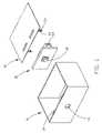
- FIG. 1is an exploded, isometric view of a computer enclosure of a preferred embodiment of the present invention, the computer enclosure including a chassis, a side panel, and a locking device;
- FIG. 2is an exploded, enlarged, isometric view of the locking device of FIG. 1 , the locking device including a body, a driving member, a pair of sliding members, and a pair of springs;
- FIG. 3is similar to FIG. 2 , but viewed from another aspect
- FIG. 4is a cutaway view of the locking device of FIG. 2 ;
- FIG. 5is an assembled, isometric view of the locking device of FIG. 2 ;
- FIG. 6is a top, cutaway view of the body and the driving member taken along line F-F of FIG. 3 showing the sliding members and the springs assembled in the body, and showing the locking device in a unlocked position;
- FIG. 7is similar to FIG. 6 , but showing the locking device in a locked position.
- an enclosure of an electronic device like a computerincludes a chassis 10 , a side panel 20 , and a locking device 30 .
- a through hole 12is defined in the chassis 10 .
- a pair of resilient clips 14is formed on a top edge of the chassis 10 .
- a pair of standing clips 22is bent down from the side panel 20 .
- a securing hole 24is defined in a distal end of each standing clip 22 .
- the locking deviceincludes a body 31 , a driving member 40 , a pair of sliding members 50 , 60 and a pair of resilient members, such as springs 80 .
- the body 31includes a front panel 32 , and a holding wall 34 extending from the front panel 32 .
- a square-shaped through opening 322is defined in the central portion of the front panel 32 , for holding the driving member 40 .
- a sliding way 36is formed in the holding wall 34 , for receiving the sliding members 50 , 60 .
- a columniform sheath 342protrudes from the holding wall 34 in the through opening 322 of the front panel 32 .
- a holding flange 3424extends inward from an edge of the sheath 342 .
- An X-shaped split 3422is defined in the sheath 342 thereby dividing the end of the sheath 342 into four resilient portions 3426 .
- a pair of columniform blocks 344is formed at opposite sides of the sheath 342 .
- a pair of locking holes 346is defined in a back portion of the holding wall 34 .
- the driving member 40includes a button 42 and a frame 44 .
- the button 42protrudes from the frame 44 and corresponds to the through hole 12 of the chassis 10 .
- a post 46extends from a back portion of the button 42 corresponding to the sheath 342 of the body 31 .
- a head 462is formed at a top portion of the post 46 for securing with the holding flange 3424 .
- the frame 44is slidingly received in the through hole 322 of the body 31 .
- a pair of slanting pushing portions 48is formed in the frame 44 .
- the sliding members 50 , 60are cuboid-shaped.
- a pair of cuneiform portions 52 , 62is respectively formed on the sliding members 50 , 60 corresponding to the pushing portions 48 in the frame 44 of the driving member 40 .
- Two contacting surfaces 522 , 622are respectively formed in the cuneiform portions 52 , 62 .
- a pair of wedge-shaped protrusions 54 , 64respectively protrudes from each end of the sliding members 50 , 60 corresponding to the securing holes 22 of the side panel 20 .
- a pair of channels 56 , 66is defined in a back portion of the sliding members 50 , 60 for holding the springs 80 .
- a pair of resilient hooks 58 , 68is formed on a back end of the sliding members 50 , 60 corresponding to the locking holes 346 of the body 31 .
- the springs 80are respectively put into the channels 56 , 66 of the sliding members 50 , 60 . Then the pair of sliding members 50 , 60 is respectively slid into the sliding way 36 from both sides thereof until the hooks 58 , 68 of the sliding members 50 , 60 are engaged into the locking holes 346 of the body 31 , the sliding members 50 , 60 are thereby secured into the body 31 .
- the post 46 of the driving member 40is engaged into the sheath 342 of the body 31 .
- the head 462is blocked by the holding flange 3424 of the sheath 342 .
- the frame 44 of the driving member 40is secured into the through opening 322 of the body 31 .
- the pushing portions 48 of the driving member 40are in contact with the contacting surfaces 522 , 622 of the sliding members 50 , 60 .
- the button 32 of the locking device 30protrudes from the through hole 12 of the chassis 10 .
- the locking device 30is secured to the chassis 10 .
- the side panel 20is positioned on top of the chassis 10 .
- the standing clips 22are pushed down to the chassis 10 toward the protrusions 54 , 64 of the sliding members 50 , 60 .
- the distal ends of the standing clips 22abut the protrusions 54 , 64 of the sliding members 50 , 60 respectively, thereby the sliding members 50 , 60 are pushed inward to slide in the sliding way 36 of the body 31 along direction B and B′ respectively.
- the springs 80 in the channels 56 , 66 of the sliding members 50 , 60are compressed.
- the sliding members 50 , 60slide back along direction B′ and B respectively due to rebounding of the springs 80 , until the sliding members 50 , 60 are stopped by way of the resilient hooks 58 , 68 of the sliding members 50 , 60 engaging in the locking holes 346 of the body 31 .
- the protrusions 54 , 64 of the sliding members 50 , 60engage in corresponding securing holes 24 of the side panel 20 , thereby securing the side panel 20 to the chassis 10 .
- the button 32 of the locking device 30is pushed in along direction A.
- the pushing portions 48 of the driving member 40abut the cuneiform portions 52 , 62 of the sliding members 50 , 60 .
- the cuneiform portions 52 , 62 of the sliding members 50 , 60are pushed in, thereby the sliding members 50 , 60 slide in the sliding way 36 of the body 31 along direction B and B′ respectively.
- the protrusions 54 , 64 of the sliding members 50 , 60are disengaged from the corresponding securing holes 24 of the side panel 20 , the side panel 20 is pushed up by the resilient clips 14 of the chassis 10 , and the side panel 20 is thereby disengaged from the chassis 10 .
Landscapes
- Engineering & Computer Science (AREA)
- Mechanical Engineering (AREA)
- Theoretical Computer Science (AREA)
- Computer Hardware Design (AREA)
- Power Engineering (AREA)
- Human Computer Interaction (AREA)
- Physics & Mathematics (AREA)
- General Engineering & Computer Science (AREA)
- General Physics & Mathematics (AREA)
- Casings For Electric Apparatus (AREA)
- Clamps And Clips (AREA)
Abstract
Description
1. Field of the Invention
The present invention relates to computer enclosures, and more particularly to a computer enclosure with a locking device for convenient attachment and removal of a side panel.
2. General Background
A conventional computer enclosure includes a chassis, and a side panel. The side panel is usually secured to the chassis with screws.
Another kind of computer enclosure is provided with a latch mechanism for assembling a housing on the chassis. The computer housing has a front panel, a side panel, and the chassis. A mechanism for latching and releasing the side panel from the chassis includes an opening defined in a side of the front panel, a latch member, a spring, and a locking hole defined in the chassis. The latch member has an arm extending towards the chassis terminating in a hooked portion to engage in the locking hole. The latch member and the spring are received in the opening and are movable between a locked position, where the arm is locked in the locking hole, and a released position, where the arm is disengaged from the locking hole. The spring urges against the base to retain the latch member in the locked position.
However, the latch is assembled to only one side of the chassis for releasing the side panel. When a pair of latches is assembled to the both sides of the chassis, two hands are needed to release the latches. It is inconvenient to disassemble the side panel from the computer enclosure.
What is needed, therefore, is a computer enclosure having a locking device, which allows the convenient assembly and removal of a side panel to/from the computer chassis.
A computer enclosure includes a chassis, a side panel, and a locking device. The side panel defines a securing hole. The locking device is attached to the chassis for locking the side panel to the chassis. The locking device includes a sliding member, a resilient member, and a driving member. The sliding member includes a cuneiform portion and a protrusion. The protrusion is engaged in the securing hole of the side panel. The resilient member is used for urging the sliding member. The driving member has a pushing portion corresponding to the cuneiform portion of the sliding member, for disengaging the protrusion of the sliding member from the securing hole of the side panel.
Other advantages and novel features will be drawn from the following detailed description of a preferred embodiment with attached drawings, in which:
Referring toFIG. 1 , an enclosure of an electronic device like a computer includes achassis 10, aside panel 20, and alocking device 30.
A throughhole 12 is defined in thechassis 10. A pair ofresilient clips 14 is formed on a top edge of thechassis 10. A pair of standingclips 22 is bent down from theside panel 20. Asecuring hole 24 is defined in a distal end of each standingclip 22.
Referring also toFIGS. 2 to 4 , the locking device includes abody 31, adriving member 40, a pair of slidingmembers springs 80.
Thebody 31 includes afront panel 32, and aholding wall 34 extending from thefront panel 32. A square-shaped throughopening 322 is defined in the central portion of thefront panel 32, for holding thedriving member 40. A slidingway 36 is formed in theholding wall 34, for receiving the slidingmembers columniform sheath 342 protrudes from theholding wall 34 in the through opening322 of thefront panel 32. Aholding flange 3424 extends inward from an edge of thesheath 342. AnX-shaped split 3422 is defined in thesheath 342 thereby dividing the end of thesheath 342 into fourresilient portions 3426. A pair ofcolumniform blocks 344 is formed at opposite sides of thesheath 342. A pair oflocking holes 346 is defined in a back portion of theholding wall 34.
Thedriving member 40 includes abutton 42 and aframe 44. Thebutton 42 protrudes from theframe 44 and corresponds to the throughhole 12 of thechassis 10. Apost 46 extends from a back portion of thebutton 42 corresponding to thesheath 342 of thebody 31. Ahead 462 is formed at a top portion of thepost 46 for securing with theholding flange 3424. Theframe 44 is slidingly received in the throughhole 322 of thebody 31. A pair of slanting pushingportions 48 is formed in theframe 44.
The slidingmembers cuneiform portions members portions 48 in theframe 44 of thedriving member 40. Two contactingsurfaces cuneiform portions shaped protrusions members holes 22 of theside panel 20. A pair ofchannels members springs 80. A pair ofresilient hooks members locking holes 346 of thebody 31.
Referring also toFIG. 5 , in assembling thelocking device 30, thesprings 80 are respectively put into thechannels members members way 36 from both sides thereof until thehooks members locking holes 346 of thebody 31, the slidingmembers body 31. Thepost 46 of the drivingmember 40 is engaged into thesheath 342 of thebody 31. Thehead 462 is blocked by the holdingflange 3424 of thesheath 342. Theframe 44 of the drivingmember 40 is secured into the throughopening 322 of thebody 31. The pushingportions 48 of the drivingmember 40 are in contact with the contactingsurfaces members
Referring also toFIGS. 6 and 7 , in assembling theside panel 20 to thechassis 10, thebutton 32 of thelocking device 30 protrudes from the throughhole 12 of thechassis 10. The lockingdevice 30 is secured to thechassis 10. Theside panel 20 is positioned on top of thechassis 10. The standing clips22 are pushed down to thechassis 10 toward theprotrusions members protrusions members members way 36 of thebody 31 along direction B and B′ respectively. Thesprings 80 in thechannels members protrusions locking device 30 are engaged in the securing holes24 of theside panel 20, the slidingmembers springs 80, until the slidingmembers resilient hooks members body 31. Then theprotrusions members holes 24 of theside panel 20, thereby securing theside panel 20 to thechassis 10.
In disassembling theside panel 20 from thechassis 10, thebutton 32 of thelocking device 30 is pushed in along direction A. The pushingportions 48 of the drivingmember 40 abut thecuneiform portions members cuneiform portions members members way 36 of thebody 31 along direction B and B′ respectively. When theprotrusions members holes 24 of theside panel 20, theside panel 20 is pushed up by theresilient clips 14 of thechassis 10, and theside panel 20 is thereby disengaged from thechassis 10. When thebutton 32 of the drivingmember 30 is released, the slidingmembers springs 80. The pushingportions member 40 are pushed back along direction A′ by thecuneiform portions member 50.
It is to be understood, however, that even though numerous characteristics and advantages have been set forth in the foregoing description of a preferred embodiment, together with details of the structure and function of the preferred embodiment, the disclosure is illustrative only, and changes may be made in detail, especially in matters of shape, size, and arrangement of parts within the principles of the invention to the full extent indicated by the broad general meaning of the terms in which the appended claims are expressed.
Claims (17)
1. A computer enclosure, comprising:
a chassis;
a side panel defining a securing hole; and
a locking device attached to the chassis for locking the side panel onto the chassis, the locking device comprising:
a body;
a sliding member received in the body, and comprising a cuneiform portion and a protrusion, the protrusion engaging in the securing hole of the side panel;
a resilient member for urging the sliding member into an original position; and
a driving member having a pushing portion corresponding to the cuneiform portion of the sliding member, for disengaging the protrusion of the sliding member from the securing hole of the side panel, wherein a sheath protrudes from the body, a post protrudes from the driving member corresponding to the sheath, and the post is received by the sheath and slidable therein, wherein a holding flange is extended inward from an edge of the sheath, and a head is formed on an end portion of the post, and the head can be stopped by the flange of the sheath.
2. The computer enclosure as described inclaim 1 , wherein the sliding member is cuboid-shaped, and the cuneiform portion and the protrusion are respectively positioned on ends of the sliding member.
3. The computer enclosure as described inclaim 1 , wherein a resilient hook is formed on the sliding member for restricting the range of movement of the sliding member, and a locking hole is defined in the body corresponding to the resilient hook.
4. The computer enclosure as described inclaim 1 , wherein a channel is formed in the sliding member for holding the resilient member, and a block protrudes from the body corresponding to the resilient member.
5. The computer enclosure as described inclaim 1 , wherein the body comprises a front panel, and a holding wall extends from the front panel, and a sliding way is formed in the holding wall for slidingly receiving the sliding member.
6. The computer enclosure as described inclaim 1 , wherein a standing clip is formed on the side panel, and the standing clip defines the securing hole therein.
7. A computer enclosure, comprising:
a chassis;
a side panel; and
a locking device attached to the chassis for locking the side panel onto the chassis, the locking device comprising:
a body defining a sliding way in a first direction;
a pair of sliding members engaged with the side panel, the pair of sliding members being slideably received in the body;
a resilient member positioned in the body for urging each sliding member to return to an original position, wherein a channel is formed in the each sliding member for holding the resilient member, and a block protrudes from the body corresponding to each resilient member; and
a driving member, a pushing portion formed on the driving member corresponding to the pair of the sliding members, wherein when the driving member is pushed in a second direction, the pushing portion urges the two sliding members to slide along the sliding way oppositely and disengage from the side panel.
8. The computer enclosure as described inclaim 7 , wherein the each sliding member comprises a cuneiform portion and a protrusion, and the cuneiform portion and the protrusion are respectively positioned on either end of the each sliding member.
9. The computer enclosure as described inclaim 7 , wherein a resilient hook is formed on the each sliding member for restricting the range of motion of the sliding member, and a locking hole is defined in the body corresponding to the resilient hook.
10. The computer enclosure as described inclaim 7 , wherein the first direction is perpendicular to the second direction.
11. The computer enclosure as described inclaim 7 , wherein the body comprises a front panel, and a holding wall extends from the front panel, and the sliding way is formed in the body.
12. The computer enclosure as described inclaim 11 , wherein a sheath protrudes from the holding wall of the body, a post protrudes from the driving member corresponding to the sheath, and the post can engage into the sheath and slide therein.
13. The computer enclosure as described inclaim 12 , wherein a holding flange extends inward from an edge of the sheath, a head is formed on an end portion of the post, and the head can be stopped by the flange of the sheath.
14. An electronic device comprising:
a chassis of said electronic device providing inner space therein for installation of components of said electronic device;
a side panel removably attachable to a side of said chassis so as to enclose said inner space together with said chassis;
a locking device installable to one of said chassis and said panel, said locking device comprising a body and a pair of sliding members received in said body, at least one protrusion formed in each of said pair of sliding members capable of engaging with the other of said chassis and said panel along a first direction to secure said panel onto said chassis, wherein a sheath protrudes from said body of said locking device, a post protrudes from said driving member corresponding to said sheath, and said post engages in said sheath and slide therein; and
a driving member held in said body, and movable along a second direction different from said first direction so as to controllably urge each of said at least one protrusion to be restorably movable for disabling engagement thereof with said other of said chassis and said panel.
15. The electronic device as described inclaim 14 , wherein said first direction and said second direction are parallel to said attached panel to said chassis and perpendicular to each other.
16. The electronic device as described inclaim 14 , wherein restoration of said engagement of said at least two protrusions with said other of said chassis and said panel is capable of urging movement of said driving member along a reverse direction to said second direction.
17. The electronic device as described inclaim 14 , wherein a holding flange extends inward from an edge of said sheath, a head is formed on an end portion of the post, and said head can be stopped by said flange of said sheath.
Applications Claiming Priority (2)
| Application Number | Priority Date | Filing Date | Title |
|---|---|---|---|
| CN200520061139.3 | 2005-07-02 | ||
| CNU2005200611393UCN2821662Y (en) | 2005-07-02 | 2005-07-02 | Casing locking device |
Publications (2)
| Publication Number | Publication Date |
|---|---|
| US20070001559A1 US20070001559A1 (en) | 2007-01-04 |
| US7410194B2true US7410194B2 (en) | 2008-08-12 |
Family
ID=37018216
Family Applications (1)
| Application Number | Title | Priority Date | Filing Date |
|---|---|---|---|
| US11/316,762Expired - Fee RelatedUS7410194B2 (en) | 2005-07-02 | 2005-12-22 | Computer enclosure with locking device |
Country Status (2)
| Country | Link |
|---|---|
| US (1) | US7410194B2 (en) |
| CN (1) | CN2821662Y (en) |
Cited By (45)
| Publication number | Priority date | Publication date | Assignee | Title |
|---|---|---|---|---|
| US20070201938A1 (en)* | 2006-02-28 | 2007-08-30 | Alps Electric Co., Ltd. | Locking mechanism for cover |
| US20070271735A1 (en)* | 2004-01-26 | 2007-11-29 | Dieter Ramsauer | Clip Fixing Element for the Assembly of Fixture Devices Such as Locks, Hinge Parts and Handles in Openings in a Thin Wall |
| US20080008572A1 (en)* | 2005-04-11 | 2008-01-10 | Ruhlander Gregory P | Tailgate lift-and-secure cable and latch assembly |
| US20080078217A1 (en)* | 2005-04-15 | 2008-04-03 | Fujitsu Limited | Lock unit for foldable housing and electronic apparatus having the same |
| US20080136197A1 (en)* | 2006-11-20 | 2008-06-12 | Jung-Hong Lin | Magnet latch |
| US20080170927A1 (en)* | 2006-10-02 | 2008-07-17 | International Business Machines Corporation | Snap together push button latch mechanism |
| US20090108593A1 (en)* | 2007-10-31 | 2009-04-30 | Hon Hai Precision Industry Co., Ltd. | Latch mechanism |
| US20090184525A1 (en)* | 2008-01-18 | 2009-07-23 | Quanta Computer Inc. | Electronic device and latch structure thereof |
| US20090213540A1 (en)* | 2008-02-21 | 2009-08-27 | Hong Fu Jin Precision Industry (Shenzhen) Co., Ltd. | Fixing apparatus for functional module |
| US20090229390A1 (en)* | 2006-08-21 | 2009-09-17 | Johnson Control Technology Company | Locking and unlocking device |
| US20090236861A1 (en)* | 2008-03-18 | 2009-09-24 | Shenzhen Futaihong Precision Industry Co., Ltd. | Battery cover latch mechanism and portable electronic device using same |
| US20090303668A1 (en)* | 2008-06-04 | 2009-12-10 | Shenzhen Futaihong Precision Industry Co., Ltd. | Battery cover latch mechanism and portable electronic device using same |
| US20100001538A1 (en)* | 2008-07-07 | 2010-01-07 | Kim Kyoungsu | Case locking device |
| US20100244465A1 (en)* | 2009-03-31 | 2010-09-30 | De Mola Manuel Loret | Two assembly parts latch system |
| US20110025074A1 (en)* | 2009-07-28 | 2011-02-03 | Jason Reznar | Dual pawl glove box latch assembly |
| US20110095547A1 (en)* | 2009-10-22 | 2011-04-28 | Shenzhen Futaihong Precision Industry Co., Ltd. | Battery cover latching mechanism |
| US20120175891A1 (en)* | 2011-01-11 | 2012-07-12 | Honda Motor Co., Ltd. | Push button assembly for opening and closing a glovebox for a vehicle |
| US8226131B1 (en)* | 2007-09-04 | 2012-07-24 | Augmentix Corporation | System, method and apparatus for door latching using a spring latch |
| US20120247023A1 (en)* | 2011-04-01 | 2012-10-04 | Hon Hai Precision Industry Co., Ltd. | Panel door and panerl using the same |
| US20140084771A1 (en)* | 2012-09-25 | 2014-03-27 | Inventec Corporation | Electronic device and movable fixing strucutre thereof |
| US20140091686A1 (en)* | 2012-10-02 | 2014-04-03 | Research In Motion Limited | Magnetic fastener apparatus and related methods |
| US20140150275A1 (en)* | 2010-12-27 | 2014-06-05 | Can Sar | Dryer comprising a dismountable member |
| US8789858B2 (en) | 2009-03-31 | 2014-07-29 | The Young Engineers, Inc. | Two assembly parts latch system |
| US20150123408A1 (en)* | 2013-11-06 | 2015-05-07 | GM Global Technology Operations LLC | Pushbutton latch mechanism for a vehicle |
| US20150135782A1 (en)* | 2013-11-04 | 2015-05-21 | Hansen International, Inc. | Push button lock |
| US20150252595A1 (en)* | 2014-03-04 | 2015-09-10 | Amesbury Group, Inc. | Deadbolt-activated supplemental lock |
| US9822561B2 (en)* | 2014-05-30 | 2017-11-21 | Pegatron Corporation | Fixing apparatus and computer apparatus using the same |
| US9957657B2 (en)* | 2015-01-30 | 2018-05-01 | Emz-Hanauer Gmbh & Co. Kgaa | Appliance lock |
| US20180232017A1 (en)* | 2017-02-16 | 2018-08-16 | Lite-On Electronics (Guangzhou) Limited | Chassis structure |
| US20190128030A1 (en)* | 2017-10-30 | 2019-05-02 | Bauer Products, Inc. | Door latch assembly |
| US10662675B2 (en) | 2017-04-18 | 2020-05-26 | Amesbury Group, Inc. | Modular electronic deadbolt systems |
| US10808424B2 (en) | 2017-05-01 | 2020-10-20 | Amesbury Group, Inc. | Modular multi-point lock |
| US10851567B2 (en)* | 2017-05-08 | 2020-12-01 | Snap-On Incorporated | Front pull latch |
| US10908656B2 (en) | 2016-06-13 | 2021-02-02 | Hewlett-Packard Development Company, L.P. | Computing devices |
| US10968661B2 (en) | 2016-08-17 | 2021-04-06 | Amesbury Group, Inc. | Locking system having an electronic deadbolt |
| US11066850B2 (en) | 2017-07-25 | 2021-07-20 | Amesbury Group, Inc | Access handle for sliding doors |
| US11241087B2 (en)* | 2019-08-29 | 2022-02-08 | Inno-Sports Co., Ltd. | Adjustment mechanism and structure having same |
| US11291297B2 (en) | 2019-10-09 | 2022-04-05 | Inno-Sports Co., Ltd. | Portable and adjustable picnic table |
| US11299920B2 (en)* | 2018-08-01 | 2022-04-12 | Ningbo Eudemon Child Protective Equipment Co., Ltd. | Locking device and refrigerator using the same |
| US11382417B2 (en) | 2020-03-05 | 2022-07-12 | Inno-Sports Co., Ltd. | Multi-foldable picnic table |
| US11441333B2 (en) | 2018-03-12 | 2022-09-13 | Amesbury Group, Inc. | Electronic deadbolt systems |
| US20220324365A1 (en)* | 2021-04-12 | 2022-10-13 | Nifco America Corp. | Modular latching system |
| US11661771B2 (en) | 2018-11-13 | 2023-05-30 | Amesbury Group, Inc. | Electronic drive for door locks |
| US11834866B2 (en) | 2018-11-06 | 2023-12-05 | Amesbury Group, Inc. | Flexible coupling for electronic deadbolt systems |
| US11918105B2 (en) | 2021-02-03 | 2024-03-05 | Inno-Sports Co., Ltd. | Picnic table with detachable table and bench |
Families Citing this family (14)
| Publication number | Priority date | Publication date | Assignee | Title |
|---|---|---|---|---|
| JP2009124292A (en)* | 2007-11-13 | 2009-06-04 | Sanyo Electric Co Ltd | Radio receiver |
| TWM351586U (en)* | 2008-08-07 | 2009-02-21 | Wistron Corp | Fixing mechanism for fixing a removable module of an electronic device |
| TWM351386U (en)* | 2008-08-26 | 2009-02-21 | Aopen Inc | Panel for computer enclosure |
| CN102053676B (en)* | 2009-10-30 | 2014-11-12 | 鸿富锦精密工业(深圳)有限公司 | Computer chassis |
| CN102566707B (en)* | 2010-12-31 | 2013-12-11 | 光宝电子(广州)有限公司 | Enclosure |
| CN103375054B (en)* | 2012-04-20 | 2015-07-01 | 纬创资通股份有限公司 | Latch mechanism suitable for electronic device and electronic device |
| US9268357B2 (en)* | 2012-11-07 | 2016-02-23 | Dell Products L.P. | Systems and methods for insertion and removal of an information handling resource |
| TWI675286B (en)* | 2018-02-09 | 2019-10-21 | 緯創資通股份有限公司 | Server unit and server |
| US10470561B2 (en)* | 2018-03-30 | 2019-11-12 | Lifetime Products, Inc. | Height adjustment mechanism |
| CN110505780A (en)* | 2018-05-18 | 2019-11-26 | 沅圣科技股份有限公司 | Shell waterproof buckle structure and doorbell device with shell waterproof buckle structure |
| CN109542178B (en)* | 2018-11-21 | 2020-11-24 | 英业达科技有限公司 | Computer casing |
| CN110868836B (en)* | 2019-10-31 | 2021-03-12 | 苏州浪潮智能科技有限公司 | One-key automatic unlocking device |
| TWI708884B (en)* | 2019-12-19 | 2020-11-01 | 簡文豐 | Push-and-pull latch device |
| CN118148995A (en)* | 2022-12-06 | 2024-06-07 | 手持产品公司 | Latch assembly and method of coupling and decoupling a latch assembly to a device |
Citations (10)
| Publication number | Priority date | Publication date | Assignee | Title |
|---|---|---|---|---|
| US2905493A (en)* | 1955-03-28 | 1959-09-22 | Tocchetto Virgil Dante | Twin latch mechanism |
| US3919866A (en)* | 1972-10-20 | 1975-11-18 | Des Brevets Neiman Soc D Expl | Lock with push-button operated bolt |
| US6296334B1 (en)* | 1999-08-10 | 2001-10-02 | Hon Hai Precision Ind. Co., Ltd. | Latch mechanism for a housing |
| US6471263B1 (en)* | 1999-12-10 | 2002-10-29 | Hyundai Motor Company | Glass release button assembly of automotive tailgate |
| US6575503B1 (en)* | 1998-03-09 | 2003-06-10 | Southco, Inc. | Latch |
| US6699243B2 (en)* | 2001-09-19 | 2004-03-02 | Curon Medical, Inc. | Devices, systems and methods for treating tissue regions of the body |
| US20040075282A1 (en)* | 2002-10-19 | 2004-04-22 | Ira Silverman | Computer quick release latch |
| US6926315B2 (en)* | 2003-01-29 | 2005-08-09 | Hardware Specialties, Inc. | Push pull latch bolt mechanism |
| US20050286217A1 (en)* | 2004-06-28 | 2005-12-29 | Samsung Electronics Co., Ltd. | Computer with a detachable main casing cover and a method of assembling same |
| US7152443B2 (en)* | 2005-01-10 | 2006-12-26 | Universal Scientific Industrial Co., Ltd. | Lockable case |
- 2005
- 2005-07-02CNCNU2005200611393Upatent/CN2821662Y/ennot_activeExpired - Fee Related
- 2005-12-22USUS11/316,762patent/US7410194B2/ennot_activeExpired - Fee Related
Patent Citations (10)
| Publication number | Priority date | Publication date | Assignee | Title |
|---|---|---|---|---|
| US2905493A (en)* | 1955-03-28 | 1959-09-22 | Tocchetto Virgil Dante | Twin latch mechanism |
| US3919866A (en)* | 1972-10-20 | 1975-11-18 | Des Brevets Neiman Soc D Expl | Lock with push-button operated bolt |
| US6575503B1 (en)* | 1998-03-09 | 2003-06-10 | Southco, Inc. | Latch |
| US6296334B1 (en)* | 1999-08-10 | 2001-10-02 | Hon Hai Precision Ind. Co., Ltd. | Latch mechanism for a housing |
| US6471263B1 (en)* | 1999-12-10 | 2002-10-29 | Hyundai Motor Company | Glass release button assembly of automotive tailgate |
| US6699243B2 (en)* | 2001-09-19 | 2004-03-02 | Curon Medical, Inc. | Devices, systems and methods for treating tissue regions of the body |
| US20040075282A1 (en)* | 2002-10-19 | 2004-04-22 | Ira Silverman | Computer quick release latch |
| US6926315B2 (en)* | 2003-01-29 | 2005-08-09 | Hardware Specialties, Inc. | Push pull latch bolt mechanism |
| US20050286217A1 (en)* | 2004-06-28 | 2005-12-29 | Samsung Electronics Co., Ltd. | Computer with a detachable main casing cover and a method of assembling same |
| US7152443B2 (en)* | 2005-01-10 | 2006-12-26 | Universal Scientific Industrial Co., Ltd. | Lockable case |
Cited By (65)
| Publication number | Priority date | Publication date | Assignee | Title |
|---|---|---|---|---|
| US20070271735A1 (en)* | 2004-01-26 | 2007-11-29 | Dieter Ramsauer | Clip Fixing Element for the Assembly of Fixture Devices Such as Locks, Hinge Parts and Handles in Openings in a Thin Wall |
| US9617754B2 (en)* | 2004-01-26 | 2017-04-11 | Dieter Ramsauer | Clip fixing element for the assembly of fixture devices such as locks, hinge parts and handles in openings in a thin wall |
| US20080008572A1 (en)* | 2005-04-11 | 2008-01-10 | Ruhlander Gregory P | Tailgate lift-and-secure cable and latch assembly |
| US7637552B2 (en)* | 2005-04-11 | 2009-12-29 | Dura Global Technologies, Inc. | Tailgate lift-and-secure cable and latch assembly |
| US7889488B2 (en) | 2005-04-15 | 2011-02-15 | Fujitsu Limited | Electronic apparatus having lock unit |
| US20080078217A1 (en)* | 2005-04-15 | 2008-04-03 | Fujitsu Limited | Lock unit for foldable housing and electronic apparatus having the same |
| US20100172074A1 (en)* | 2005-04-15 | 2010-07-08 | Fujitsu Limited | Electronic apparatus having lock unit |
| US7665774B2 (en)* | 2005-04-15 | 2010-02-23 | Fujitsu Limited | Lock unit for foldable housing and electronic apparatus having the same |
| US20070201938A1 (en)* | 2006-02-28 | 2007-08-30 | Alps Electric Co., Ltd. | Locking mechanism for cover |
| US20090229390A1 (en)* | 2006-08-21 | 2009-09-17 | Johnson Control Technology Company | Locking and unlocking device |
| US20080170927A1 (en)* | 2006-10-02 | 2008-07-17 | International Business Machines Corporation | Snap together push button latch mechanism |
| US20080136197A1 (en)* | 2006-11-20 | 2008-06-12 | Jung-Hong Lin | Magnet latch |
| US7543862B2 (en)* | 2006-11-20 | 2009-06-09 | Inventec Corporation | Magnet latch |
| US8757674B2 (en) | 2007-09-04 | 2014-06-24 | Dell Products, Lp | System, method and apparatus for door latching using a spring latch |
| US8226131B1 (en)* | 2007-09-04 | 2012-07-24 | Augmentix Corporation | System, method and apparatus for door latching using a spring latch |
| US20090108593A1 (en)* | 2007-10-31 | 2009-04-30 | Hon Hai Precision Industry Co., Ltd. | Latch mechanism |
| US20090184525A1 (en)* | 2008-01-18 | 2009-07-23 | Quanta Computer Inc. | Electronic device and latch structure thereof |
| US20090213540A1 (en)* | 2008-02-21 | 2009-08-27 | Hong Fu Jin Precision Industry (Shenzhen) Co., Ltd. | Fixing apparatus for functional module |
| US7789438B2 (en)* | 2008-03-18 | 2010-09-07 | Shenzhen Futaihong Precision Industry Co., Ltd. | Battery cover latch mechanism and portable electronic device using same |
| US20090236861A1 (en)* | 2008-03-18 | 2009-09-24 | Shenzhen Futaihong Precision Industry Co., Ltd. | Battery cover latch mechanism and portable electronic device using same |
| US7789439B2 (en)* | 2008-06-04 | 2010-09-07 | Shenzhen Futaihong Precision Industry Co., Ltd. | Battery cover latch mechanism and portable electronic device using same |
| US20090303668A1 (en)* | 2008-06-04 | 2009-12-10 | Shenzhen Futaihong Precision Industry Co., Ltd. | Battery cover latch mechanism and portable electronic device using same |
| US20100001538A1 (en)* | 2008-07-07 | 2010-01-07 | Kim Kyoungsu | Case locking device |
| US8419085B2 (en)* | 2008-07-07 | 2013-04-16 | Humax Co., Ltd. | Case locking device |
| US8757675B2 (en)* | 2009-03-31 | 2014-06-24 | The Young Engineers, Inc. | Two assembly parts latch system |
| US8534718B2 (en) | 2009-03-31 | 2013-09-17 | The Young Engineers, Inc. | Two assembly parts latch system |
| US20100244465A1 (en)* | 2009-03-31 | 2010-09-30 | De Mola Manuel Loret | Two assembly parts latch system |
| US8789858B2 (en) | 2009-03-31 | 2014-07-29 | The Young Engineers, Inc. | Two assembly parts latch system |
| US20110025074A1 (en)* | 2009-07-28 | 2011-02-03 | Jason Reznar | Dual pawl glove box latch assembly |
| US20110095547A1 (en)* | 2009-10-22 | 2011-04-28 | Shenzhen Futaihong Precision Industry Co., Ltd. | Battery cover latching mechanism |
| US9745686B2 (en)* | 2010-12-27 | 2017-08-29 | Arcelik Anonim Sirketi | Dryer comprising a dismountable member |
| US20140150275A1 (en)* | 2010-12-27 | 2014-06-05 | Can Sar | Dryer comprising a dismountable member |
| US8740262B2 (en)* | 2011-01-11 | 2014-06-03 | Honda Motor Co., Ltd. | Push button assembly for opening and closing a glovebox for a vehicle |
| US20120175891A1 (en)* | 2011-01-11 | 2012-07-12 | Honda Motor Co., Ltd. | Push button assembly for opening and closing a glovebox for a vehicle |
| US20120247023A1 (en)* | 2011-04-01 | 2012-10-04 | Hon Hai Precision Industry Co., Ltd. | Panel door and panerl using the same |
| US8840200B2 (en)* | 2012-09-25 | 2014-09-23 | Inventec (Pudong) Technology Corporation | Electronic device and movable fixing structure thereof |
| US20140084771A1 (en)* | 2012-09-25 | 2014-03-27 | Inventec Corporation | Electronic device and movable fixing strucutre thereof |
| US20140091686A1 (en)* | 2012-10-02 | 2014-04-03 | Research In Motion Limited | Magnetic fastener apparatus and related methods |
| US20150135782A1 (en)* | 2013-11-04 | 2015-05-21 | Hansen International, Inc. | Push button lock |
| US20150123408A1 (en)* | 2013-11-06 | 2015-05-07 | GM Global Technology Operations LLC | Pushbutton latch mechanism for a vehicle |
| US20150252595A1 (en)* | 2014-03-04 | 2015-09-10 | Amesbury Group, Inc. | Deadbolt-activated supplemental lock |
| US9822561B2 (en)* | 2014-05-30 | 2017-11-21 | Pegatron Corporation | Fixing apparatus and computer apparatus using the same |
| US9957657B2 (en)* | 2015-01-30 | 2018-05-01 | Emz-Hanauer Gmbh & Co. Kgaa | Appliance lock |
| US10908656B2 (en) | 2016-06-13 | 2021-02-02 | Hewlett-Packard Development Company, L.P. | Computing devices |
| US10968661B2 (en) | 2016-08-17 | 2021-04-06 | Amesbury Group, Inc. | Locking system having an electronic deadbolt |
| US10386895B2 (en)* | 2017-02-16 | 2019-08-20 | Lite-On Electronics (Guangzhou) Limited | Chassis structure |
| US20180232017A1 (en)* | 2017-02-16 | 2018-08-16 | Lite-On Electronics (Guangzhou) Limited | Chassis structure |
| US11634931B2 (en) | 2017-04-18 | 2023-04-25 | Amesbury Group, Inc. | Modular electronic deadbolt systems |
| US10662675B2 (en) | 2017-04-18 | 2020-05-26 | Amesbury Group, Inc. | Modular electronic deadbolt systems |
| US10808424B2 (en) | 2017-05-01 | 2020-10-20 | Amesbury Group, Inc. | Modular multi-point lock |
| US10851567B2 (en)* | 2017-05-08 | 2020-12-01 | Snap-On Incorporated | Front pull latch |
| US11066850B2 (en) | 2017-07-25 | 2021-07-20 | Amesbury Group, Inc | Access handle for sliding doors |
| US20190128030A1 (en)* | 2017-10-30 | 2019-05-02 | Bauer Products, Inc. | Door latch assembly |
| US10988963B2 (en)* | 2017-10-30 | 2021-04-27 | Bauer Products, Inc. | Door latch assembly |
| US11441333B2 (en) | 2018-03-12 | 2022-09-13 | Amesbury Group, Inc. | Electronic deadbolt systems |
| US11299920B2 (en)* | 2018-08-01 | 2022-04-12 | Ningbo Eudemon Child Protective Equipment Co., Ltd. | Locking device and refrigerator using the same |
| US11834866B2 (en) | 2018-11-06 | 2023-12-05 | Amesbury Group, Inc. | Flexible coupling for electronic deadbolt systems |
| US11661771B2 (en) | 2018-11-13 | 2023-05-30 | Amesbury Group, Inc. | Electronic drive for door locks |
| US11241087B2 (en)* | 2019-08-29 | 2022-02-08 | Inno-Sports Co., Ltd. | Adjustment mechanism and structure having same |
| US11291297B2 (en) | 2019-10-09 | 2022-04-05 | Inno-Sports Co., Ltd. | Portable and adjustable picnic table |
| US11382417B2 (en) | 2020-03-05 | 2022-07-12 | Inno-Sports Co., Ltd. | Multi-foldable picnic table |
| US11918105B2 (en) | 2021-02-03 | 2024-03-05 | Inno-Sports Co., Ltd. | Picnic table with detachable table and bench |
| US11918106B2 (en) | 2021-02-03 | 2024-03-05 | Inno-Sports Co., Ltd. | Picnic table with detachable table and bench |
| US20220324365A1 (en)* | 2021-04-12 | 2022-10-13 | Nifco America Corp. | Modular latching system |
| US11999282B2 (en)* | 2021-04-12 | 2024-06-04 | Nifco America Corp. | Modular latching system |
Also Published As
| Publication number | Publication date |
|---|---|
| CN2821662Y (en) | 2006-09-27 |
| US20070001559A1 (en) | 2007-01-04 |
Similar Documents
| Publication | Publication Date | Title |
|---|---|---|
| US7410194B2 (en) | Computer enclosure with locking device | |
| US7265987B2 (en) | Mounting assembly for data storage device | |
| US6751093B1 (en) | Mounting device assembly for data storage device | |
| US7447013B2 (en) | Mounting apparatus for storage device | |
| US7489502B2 (en) | Latching mechanism for a foldable electronic device | |
| US8009424B2 (en) | Latching device and electronic device using the same | |
| JP3749503B2 (en) | Computer casing | |
| US8411429B2 (en) | Mounting apparatus for disk drive | |
| US8009416B2 (en) | Retaining apparatus for data storage device | |
| US20080239647A1 (en) | Latching mechanism | |
| US7480132B2 (en) | Portable computer having improved latch mechanism | |
| US7261383B2 (en) | Computer enclosure with latch device | |
| US7974092B2 (en) | Computer enclosure with cover mounting apparatus | |
| US8220756B2 (en) | Mounting apparatus for data storage device | |
| US20040214077A1 (en) | Battery locking apparatus for electronic device | |
| US20070247791A1 (en) | Latch mechanism | |
| US20090134636A1 (en) | Latch mechanism | |
| US8899700B2 (en) | Housing having a carrier device | |
| US20090108593A1 (en) | Latch mechanism | |
| US7679904B2 (en) | Housing of foldable electronic device | |
| US20060221567A1 (en) | Latch mechanism for portable computer | |
| US7408768B2 (en) | Mounting apparatus for data storage device | |
| US7204469B2 (en) | Mounting apparatus for securing storage device | |
| US20130163208A1 (en) | Electronic device with lock mechanism | |
| US20120169197A1 (en) | Chassis assembly |
Legal Events
| Date | Code | Title | Description |
|---|---|---|---|
| AS | Assignment | Owner name:HON HAI PRECISION INDUSTRY CO., LTD., TAIWAN Free format text:ASSIGNMENT OF ASSIGNORS INTEREST;ASSIGNORS:CHEN, YUN-LUNG;XIAO, YU-MING;REEL/FRAME:017415/0059 Effective date:20051205 | |
| AS | Assignment | Owner name:HONG FU JIN PRECISION INDUSTRY (SHENZHEN) CO., LTD Free format text:ASSIGNMENT OF ASSIGNORS INTEREST;ASSIGNOR:HON HAI PRECISION INDUSTRY CO., LTD.;REEL/FRAME:021074/0528 Effective date:20080515 Owner name:HON HAI PRECISION INDUSTRY CO., LTD., TAIWAN Free format text:ASSIGNMENT OF ASSIGNORS INTEREST;ASSIGNOR:HON HAI PRECISION INDUSTRY CO., LTD.;REEL/FRAME:021074/0528 Effective date:20080515 | |
| REMI | Maintenance fee reminder mailed | ||
| LAPS | Lapse for failure to pay maintenance fees | ||
| STCH | Information on status: patent discontinuation | Free format text:PATENT EXPIRED DUE TO NONPAYMENT OF MAINTENANCE FEES UNDER 37 CFR 1.362 | |
| FP | Lapsed due to failure to pay maintenance fee | Effective date:20120812 |