US7408582B2 - Methods for configuring a digital camera and for display digital images - Google Patents
Methods for configuring a digital camera and for display digital imagesDownload PDFInfo
- Publication number
- US7408582B2 US7408582B2US10/850,145US85014504AUS7408582B2US 7408582 B2US7408582 B2US 7408582B2US 85014504 AUS85014504 AUS 85014504AUS 7408582 B2US7408582 B2US 7408582B2
- Authority
- US
- United States
- Prior art keywords
- digital
- camera
- digital camera
- user
- images
- Prior art date
- Legal status (The legal status is an assumption and is not a legal conclusion. Google has not performed a legal analysis and makes no representation as to the accuracy of the status listed.)
- Expired - Lifetime, expires
Links
Images


Classifications
- G—PHYSICS
- G06—COMPUTING OR CALCULATING; COUNTING
- G06F—ELECTRIC DIGITAL DATA PROCESSING
- G06F8/00—Arrangements for software engineering
- G06F8/60—Software deployment
- H—ELECTRICITY
- H04—ELECTRIC COMMUNICATION TECHNIQUE
- H04N—PICTORIAL COMMUNICATION, e.g. TELEVISION
- H04N1/00—Scanning, transmission or reproduction of documents or the like, e.g. facsimile transmission; Details thereof
- H04N1/00127—Connection or combination of a still picture apparatus with another apparatus, e.g. for storage, processing or transmission of still picture signals or of information associated with a still picture
- H04N1/00132—Connection or combination of a still picture apparatus with another apparatus, e.g. for storage, processing or transmission of still picture signals or of information associated with a still picture in a digital photofinishing system, i.e. a system where digital photographic images undergo typical photofinishing processing, e.g. printing ordering
- H—ELECTRICITY
- H04—ELECTRIC COMMUNICATION TECHNIQUE
- H04N—PICTORIAL COMMUNICATION, e.g. TELEVISION
- H04N1/00—Scanning, transmission or reproduction of documents or the like, e.g. facsimile transmission; Details thereof
- H04N1/00127—Connection or combination of a still picture apparatus with another apparatus, e.g. for storage, processing or transmission of still picture signals or of information associated with a still picture
- H04N1/00204—Connection or combination of a still picture apparatus with another apparatus, e.g. for storage, processing or transmission of still picture signals or of information associated with a still picture with a digital computer or a digital computer system, e.g. an internet server
- H04N1/00244—Connection or combination of a still picture apparatus with another apparatus, e.g. for storage, processing or transmission of still picture signals or of information associated with a still picture with a digital computer or a digital computer system, e.g. an internet server with a server, e.g. an internet server
- H—ELECTRICITY
- H04—ELECTRIC COMMUNICATION TECHNIQUE
- H04N—PICTORIAL COMMUNICATION, e.g. TELEVISION
- H04N1/00—Scanning, transmission or reproduction of documents or the like, e.g. facsimile transmission; Details thereof
- H04N1/0035—User-machine interface; Control console
- H04N1/00501—Tailoring a user interface [UI] to specific requirements
- H04N1/00503—Customising to a particular machine or model, machine function or application
- H—ELECTRICITY
- H04—ELECTRIC COMMUNICATION TECHNIQUE
- H04N—PICTORIAL COMMUNICATION, e.g. TELEVISION
- H04N1/00—Scanning, transmission or reproduction of documents or the like, e.g. facsimile transmission; Details thereof
- H04N1/0035—User-machine interface; Control console
- H04N1/00501—Tailoring a user interface [UI] to specific requirements
- H04N1/00509—Personalising for a particular user or group of users, e.g. a workgroup or company
- H—ELECTRICITY
- H04—ELECTRIC COMMUNICATION TECHNIQUE
- H04N—PICTORIAL COMMUNICATION, e.g. TELEVISION
- H04N1/00—Scanning, transmission or reproduction of documents or the like, e.g. facsimile transmission; Details thereof
- H04N1/00962—Input arrangements for operating instructions or parameters, e.g. updating internal software
- H04N1/0097—Storage of instructions or parameters, e.g. customised instructions or different parameters for different user IDs
- H—ELECTRICITY
- H04—ELECTRIC COMMUNICATION TECHNIQUE
- H04N—PICTORIAL COMMUNICATION, e.g. TELEVISION
- H04N1/00—Scanning, transmission or reproduction of documents or the like, e.g. facsimile transmission; Details thereof
- H04N1/00962—Input arrangements for operating instructions or parameters, e.g. updating internal software
- H04N1/00973—Input arrangements for operating instructions or parameters, e.g. updating internal software from a remote device, e.g. receiving via the internet instructions input to a computer terminal
- H—ELECTRICITY
- H04—ELECTRIC COMMUNICATION TECHNIQUE
- H04N—PICTORIAL COMMUNICATION, e.g. TELEVISION
- H04N1/00—Scanning, transmission or reproduction of documents or the like, e.g. facsimile transmission; Details thereof
- H04N1/21—Intermediate information storage
- H04N1/2104—Intermediate information storage for one or a few pictures
- H04N1/2112—Intermediate information storage for one or a few pictures using still video cameras
- H—ELECTRICITY
- H04—ELECTRIC COMMUNICATION TECHNIQUE
- H04N—PICTORIAL COMMUNICATION, e.g. TELEVISION
- H04N1/00—Scanning, transmission or reproduction of documents or the like, e.g. facsimile transmission; Details thereof
- H04N1/21—Intermediate information storage
- H04N1/2104—Intermediate information storage for one or a few pictures
- H04N1/2158—Intermediate information storage for one or a few pictures using a detachable storage unit
- H—ELECTRICITY
- H04—ELECTRIC COMMUNICATION TECHNIQUE
- H04N—PICTORIAL COMMUNICATION, e.g. TELEVISION
- H04N1/00—Scanning, transmission or reproduction of documents or the like, e.g. facsimile transmission; Details thereof
- H04N1/32—Circuits or arrangements for control or supervision between transmitter and receiver or between image input and image output device, e.g. between a still-image camera and its memory or between a still-image camera and a printer device
- H04N1/32101—Display, printing, storage or transmission of additional information, e.g. ID code, date and time or title
- H04N1/32106—Display, printing, storage or transmission of additional information, e.g. ID code, date and time or title separate from the image data, e.g. in a different computer file
- H04N1/32122—Display, printing, storage or transmission of additional information, e.g. ID code, date and time or title separate from the image data, e.g. in a different computer file in a separate device, e.g. in a memory or on a display separate from image data
- H—ELECTRICITY
- H04—ELECTRIC COMMUNICATION TECHNIQUE
- H04N—PICTORIAL COMMUNICATION, e.g. TELEVISION
- H04N23/00—Cameras or camera modules comprising electronic image sensors; Control thereof
- H04N23/60—Control of cameras or camera modules
- H04N23/617—Upgrading or updating of programs or applications for camera control
- H—ELECTRICITY
- H04—ELECTRIC COMMUNICATION TECHNIQUE
- H04N—PICTORIAL COMMUNICATION, e.g. TELEVISION
- H04N23/00—Cameras or camera modules comprising electronic image sensors; Control thereof
- H04N23/60—Control of cameras or camera modules
- H04N23/63—Control of cameras or camera modules by using electronic viewfinders
- H04N23/631—Graphical user interfaces [GUI] specially adapted for controlling image capture or setting capture parameters
- H—ELECTRICITY
- H04—ELECTRIC COMMUNICATION TECHNIQUE
- H04N—PICTORIAL COMMUNICATION, e.g. TELEVISION
- H04N2101/00—Still video cameras
- H—ELECTRICITY
- H04—ELECTRIC COMMUNICATION TECHNIQUE
- H04N—PICTORIAL COMMUNICATION, e.g. TELEVISION
- H04N2201/00—Indexing scheme relating to scanning, transmission or reproduction of documents or the like, and to details thereof
- H04N2201/0008—Connection or combination of a still picture apparatus with another apparatus
- H04N2201/0074—Arrangements for the control of a still picture apparatus by the connected apparatus
- H—ELECTRICITY
- H04—ELECTRIC COMMUNICATION TECHNIQUE
- H04N—PICTORIAL COMMUNICATION, e.g. TELEVISION
- H04N2201/00—Indexing scheme relating to scanning, transmission or reproduction of documents or the like, and to details thereof
- H04N2201/0077—Types of the still picture apparatus
- H04N2201/0084—Digital still camera
Definitions
- This inventionrelates generally to the field of digital cameras, and in particular, to customizing digital cameras for particular users.
- Digital camerassuch as the Kodak DC260 TM digital camera, sold by the Eastman Kodak Company, enable images to be utilized on a home personal computer (PC), printed locally or remotely, and incorporated into e-mail documents and personal World-Wide-Web home pages which can be accessed via the Internet.
- the camera's graphic user interfaceenables many different features to be selected, but it is complicated, and thus, very difficult for a first-time user to understand.
- the cameraprovides a fixed set of features to the end user. These features can be controlled by Digital Scripts specified by Flashpoint, Inc.
- Digital Scriptsare ASCII text files created with a text editor on a host computer. Such Scripts may be invoked to select particular camera features and to perform a defined sequence of camera operations. For example, a Script may capture an exposure series of still pictures using different exposure settings.
- the firmware in the DC260TM digital cameracan be replaced via a memory card, as described in commonly-assigned U.S. Pat. No. 5,477,264, entitled “Electronic Imaging System Using A Removable Software-Enhanced Storage Device,” the disclosure of which is herein incorporated by reference. Images can be assigned to albums, as described in commonly-assigned U.S. Pat. No. 5,633,678, entitled “Electronic Still Camera For Capturing And Categorizing Images,” the disclosure of which is herein incorporated by reference.
- a method for customizing a digital camera for at least one particular userincluding a reprogrammable memory for storing firmware which controls the operation of the digital camera and a camera graphical user interface responsive to the firmware stored in the reprogrammable memory, the firmware including at least one firmware component, the method comprising the steps of:
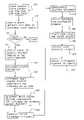
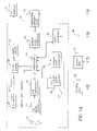
- FIGS. 1A and 1Btaken together, are a block diagram of a digital imaging system in accordance with the present invention for providing a user customizable digital camera 10 ;
- FIG. 2is a flow diagram depicting the steps used in customizing the digital camera 10 of FIG. 1A .
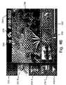
- FIG. 3illustrates a graphical screen displayed on the display monitor 52 of FIG. 1B in the process of customizing the digital camera 10 of FIG. 1A ;
- FIGS. 4A and 4Billustrate two different camera graphical user interface screens displayed on the color image display 22 of the digital camera 10 of FIG. 1A for two different users;
- FIG. 4Cis a rear view of the digital camera 10 including the color image display 22 ;
- FIG. 5illustrates an additional graphical screen displayed on the display monitor 52 of FIG. 1B in the process of customizing the digital camera 10 of FIG. 1A , which includes a depiction of the camera graphical user interface of the digital camera 10 of FIG. 1A ;
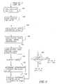
- FIG. 6illustrates an alternative embodiment of several steps of the process depicted in FIG. 2 ;
- FIG. 7depicts several graphical screens used in the process of FIG. 6 ;
- FIG. 8is a flow diagram depicting image processing operations performed within the digital camera 10 of FIG. 1A ;
- FIG. 9depicts three tone correction curves that can be used in block 530 of FIG. 8 ;
- FIG. 10depicts three Coring look-up tables that can be used in block 540 of FIG. 8 .
- FIG. 1is a block diagram of a digital imaging system in accordance with the present invention, which enables users to easily customize the interface and features of their digital camera prior to taking pictures.
- the digital imaging systemincludes a digital camera 10 which is supplied along with camera customization software provided on a compact disc CD-ROM 32 , a floppy disk 34 , or other digital media.
- the digital imaging systemalso includes a host computer 40 , such as a Dell Dimension XPS M200, and a Network Service Provider 70 .
- camera customization softwareis executed external to the digital camera 10 , and is typically executed on the host computer 40 .
- the camera customization softwareaccesses software code which permits firmware in the digital camera 10 to be customized by a user.
- the software codecan be source code which is compiled by the camera customization software to create executable firmware.
- the software codecan be compiled firmware components or firmware settings which are accessed by the camera customization software.
- the camera customization softwarecan modify or combine firmware components in order to provide firmware which customizes the digital camera 10 .
- the camera customization softwarealso includes one or more applications that provide a series of interactive dialogues with the user so that the user may learn about available camera features and select features of interest.
- the digital camera 10produces digital images that are stored on a removable memory card 30 .
- the digital camera 10includes an optical viewfinder 11 . (shown in FIG. 4C ) for composing a scene (not shown), a 3:1 zoom lens 12 controlled by a zoom switch 13 (shown in FIG. 4C ) having telephoto (T) and wide angle (W) positions and having zoom and focus motor drives (not shown), and an adjustable aperture and shutter (not shown) for focusing light from a scene on an image sensor 14 .
- the image sensor 14can be, for example, a single-chip color charge-coupled device (CCD), using the well-known Bayer color filter pattern.
- a shutter button 15shown in FIG.
- the analog output signal from the image sensor 14is converted to digital data by an analog-to-digital (A/D) converter 16 .
- the digital datais processed by a processor 18 controlled by firmware stored in a reprogrammable memory, such as a Flash EPROM 28 .
- the processed digital image fileis provided to a memory card interface 20 which stores the digital image file on the removable memory card 30 or on another type of digital memory device, such as a floppy disk or magnetic hard drive.
- the removable memory card 30which is well-known to those skilled in the art, can include, for example, a memory card adapted to the PCMCIA card interface standard, as described in the PC Card Standard, Release 2.0, published by the Personal Computer Memory Card international Association, Sunnyvale, Calif, Sep. 1991.
- the removable memory card 30can also be adapted to the Compact Flash interface standard, such as described in the Compact Flash Specification Version 1.3, published by the Compact Flash Association, Palo Alto, Calif, Aug. 5, 1998, or to other memory devices such as the well-known SSFDC (Solid State Floppy Disc Card) or Memory Stick formats.
- SSFDCSolid State Floppy Disc Card
- the processor 18performs color interpolation followed by color and tone correction, in order to produce rendered sRGB image data. This processing is described later with reference to FIG. 8 .
- the processor 18can include internal buffer memory to store a portion of the image, or to store one or more images. Alternatively, the processor 18 can use a separate external memory (not shown), such as DRAM memory.
- the rendered sRGB image datais then JPEG compressed and stored as a JPEG image file on the removable memory card 30 .
- the processor 18also provides a lower resolution or “thumbnail” size image data to a color image display 22 , such as a color liquid crystal display (LCD), which displays the captured image for the user to review.
- a color image display 22such as a color liquid crystal display (LCD)
- a camera user interface 24including a series of user buttons 80 , 81 , 82 , 83 , and 84 (shown in FIG. 4C ) and a capture/review mode switch 86 (shown in FIG. 4C ), is used to control the digital camera 10 .
- the camera user interface 24together with text and icons displayed on the image display 22 (shown also in FIG. 4C ), forms the camera graphical user interface (GUI). This GUI is controlled by the user interface portion of the firmware stored in the Flash EPROM 28 .
- the digital camera 10can also include a digital-to-analog (D/A) converter 27 and a miniature speaker 29 (also shown in FIG.
- D/Adigital-to-analog
- the digital camera 10can also include a video output driver 23 which connects to a TV display 31 , such as an NTSC format home television, for displaying the captured images on the TV display 31 .
- the digital camera 10further includes a strobe flash unit (not shown) for illuminating the subject when the ambient illumination level is low.
- the removable memory card 30can be inserted into a memory card reader 48 in the host computer 40 .
- an interface cable 36can be used to connect between a host interface 26 in the digital camera 10 and a camera interface 46 in the host computer 40 .
- the interface cable 36may conform to, for example, the well-know universal serial bus (USB) interface specification.
- the captured images from the digital camera 10can be downloaded to the host computer 40 and stored on a hard drive 56 under the control of a central processing unit (CPU) 50 .
- the CPU 50is coupled to a display monitor 52 , which is used to view the images, and a keyboard 54 .
- a mouse 55permits the user to readily communicate with the CPU 50 .
- the CPU 50communicates with a 25 local printer 58 , such as an Epson Stylus Photo 700 printer, which produces hard copy prints of the images captured by the digital camera 10 .
- the digital camera 10 that is supplied to a userincludes firmware stored in the Flash EPROM 28 which provides normal camera features. Users can customize the look and feel, and the functions offered by the digital camera 10 , using the camera customization software provided with the digital camera 10 .
- This camera customization softwareis provided on the CD-ROM disc 32 , which is loaded into the host computer 40 via the CD-ROM drive 42 , or provided on the floppy disk 34 , which is loaded into the host computer 40 via the floppy disk drive 44 .
- the CD-ROM disc 32 or the floppy disk 34can also include digital image application software, such as the Picture EasyTM version 3.1 software developed by the Eastman Kodak Company.
- all of the camera customization softwarecould be downloaded from the Network Service Provider 70 via a modem 60 .
- the modem 60communicates with a modem 72 at the Network Service Provider 70 , which is connected to a computer 74 , a camera firmware database 76 , and a billing system 78 which can charge the user (e.g., via a credit card) for downloading the camera customization software.
- the CPU 50uses the camera customization software in accordance with the present invention to provide custom firmware code which is downloaded under the control of processor 18 of the digital camera 10 via the removable memory card 30 , and stored in the Flash EPROM 28 , as described in commonly-assigned U.S. Pat. No.
- FIG. 2is a flow diagram depicting the steps used in customizing the digital camera 10 of FIG. 1 in accordance with a preferred embodiment of the present invention.
- the camera customization softwareis automatically launched (block 100 ) and executed by the CPU 50 .
- the useris informed, via the display monitor 52 , of the user's ability to enhance the capability of his/her newly purchased digital camera 10 and asked if the user wishes to do so at the present time (block 110 ). If the user responds “yes” (block 120 ), the user is asked to connect his/her digital camera 10 to the host computer 40 via the interface cable 36 (block 125 .
- the camera customization softwaredetermines the capabilities of the digital camera 10 and an inventory of the features currently provided by the Flash EPROM 28 .
- the capabilities of the digital camera 10can be determined either by determining the camera model number or by determining the types of hardware features that the digital camera 10 can support and by the size of the memory of the Flash EPROM 28 .
- the camera customization softwaredetermines which feature firmware components are available for this particular model camera via the software provided on the CD-ROM disc 32 .
- the camera customization softwareuses the modem 60 to determine whether the firmware components which provide the new features not stored on the CD-ROM disc 32 are available within the camera firmware database 76 at the Network Service Provider 70 .
- the response from the Network Service Provider 70received by the host computer 40 , might include some firmware components that are available to the user at no charge, and other firmware components for which the user will be charged.
- the Network Service Provider 70can track whether the user has previously purchased firmware components so that they can be downloaded again at no charge if the firmware component was lost by the user, or is otherwise unavailable. Further, the Network Service Provider 70 could offer discounts to the user based on previous purchases.
- the features provided by the available firmware componentsare displayed to the user on the display monitor 52 through an on-screen listing of these features.
- An example screen 53 listing available featuresis shown in FIG. 3 .
- the screen 53lists the available camera firmware memory in a window 305 , and the features that the user can select in a product option window 310 .
- a scroll bar 312 having an up arrow 314 and a down arrow 316permits the user to scroll through a long list of available options.
- the product option window 310also lists the amount of camera firmware memory needed to store the firmware component that provides the option, and the cost of the option.
- a description window 340provides a brief description of the option in this example, the option is a package of features designed for the Halloween season that includes the ability to add custom borders and special digital picture overlays with a Halloween theme. It includes two different vampire border templates, and the ability to selectively paint “blood” on pictures of faces captured by the digital camera 10 .
- the appropriate firmwarewill be added to the Flash EPROM memory 28 of the digital camera 10 in block 210 to control the processor 18 to enable the user, via the camera user interface 24 , to selectively add the vampire border templates to specific images and to paint “blood drops” in appropriate areas of the images they have captured using the digital camera 10 , as the image is displayed on the color image display 22 .
- the product option window 310can display many different types of optional features and functions, which will be described later. Some of these are listed in the product option window 310 shown in FIG. 3 ,
- the optionsinclude a “compression adjust” feature which provides compression algorithm settings appropriate for taking pictures of documents, rather than of real-world scenes.
- the optionsalso include a “red-eye elimination” option that eliminates red-eye pictures due to night flash.
- This optioncan be a flash add-on, meaning it adds a camera pre-flash mode to reduce the subject's pupil diameter or alternatively, can digitally process the captured picture using the processor 18 to identify and eliminate red-eye.
- the optionsalso include an “album” option that enables the user to upload, from the host computer 40 to the digital camera 10 , particularly memorable personal images from various sources that are stored in the Flash EPROM memory 28 , and for display on the color image display 22 or the TV display 31 .
- These “album” imagesare compressed and stored as appropriate resolution images, typically having a greatly reduced number of pixels (and therefore a much smaller file size) than the images captured by the digital camera 10 and stored in the removable memory 30 .
- the optionsfurther include a web-page generator that automatically generates an html file using the captured images, as well as one or more of the stored album images.
- This featuremay be customized by the user as part of the process depicted in FIG. 2 to produce a web page that has a customized background color or image, customized header text, customized image date format or titles, and customized image sizes.
- the usercan select a demo of one or more features that he or she would like to see demonstrated. For example, in FIG. 3 , after selecting the “Beastly Vampires” feature by clicking on line 318 , the user can select the “demo” button 322 .
- the demonstration softwareis provided from the same location which provides the corresponding firmware component (e.g., the CD-ROM 32 or Network Service Provider 70 ) in the form of a QuickTime movie, Macromedia director presentation, or another multi-media presentation that provides more information on the use and value of the particular feature.
- the userselects a “view” selector 320 .
- the userselects the feature(s) that the user wants to be included in his/her digital camera 10 . This is done by highlighting the desired options in the product option window 310 and then chooses a “select” selector 342 .
- the usercan start with a previous camera selection by selecting a “restore” selector 332 , which permits the user to select and restore a camera feature set that was previously backed up, and use that as the starting point for a new feature set.
- the purchaserselects a “purchase” selector 324 which provides a series of order menus (e.g., HTML web pages) generated by the Network Service Provider 70 and communicated to the computer 40 via the modem 60 .
- the userpays for the firmware component(s) corresponding to the selected feature(s) by providing a payment identifier into a secured electronic commerce link which specifies a particular account which is to be charged or debited.
- the payment identifiercan be a credit card number that specifies a particular credit card account. As used in this specification, a credit card will also include a debit card.
- the number of features that can be selecteddepends on the size of the firmware component(s) needed to implement the features, and the size of the firmware memory in the camera's Flash EPROM 28 .
- the useris provided with the ability to select one of a plurality of icon schemes for the camera Graphical User Interface (GUI) 25 displayed on the color image display 22 of the digital camera 10 , shown in FIG. 4C .
- GUIGraphical User Interface
- This selectionoccurs after the user selects a “next” selector 344 shown in FIG. 3 .
- Two different exemplary types of icon schemesare shown in FIGS. 4A and 48 .
- the icon schemescan use different colors, text fonts, icon styles (e.g., classic, whimsical, business), and background colors or patterns.
- the icon schemescan also include themes, such as a “Winnie the Pooh” or a “Pokemon” theme for a child, or an “X-files” or particular football team (e.g., the Green Bay Packers) theme for an adult, and the appropriate set of icons, having the appropriate text style, colors, and backgrounds will be used. Icons are provided for both the review mode features, enabled when the capture/review mode switch 86 (shown in FIG. 4C ) is set in the review position, and for capture mode features, enabled when the capture/review mode switch 86 is set in the capture position.
- FIGS. 4A and 4Bdemonstrate two different graphic user interface (GUI) screens that can be displayed on the image display 22 of the digital camera 10 .
- GUIgraphic user interface
- Each GUI screendisplays a main image 240 and provides the same basic camera functions through a scrollable list of icons 250 .
- Both icons 252 A and 252 Bcontrol the same function, but have a different appearance on the image display 22 to appeal to different types of users.
- the second icon 254 Adepict different styles of trash cans which enable the user to delete the selected picture.
- the third icon 256 A(shown in FIG. 4A ) or 256 B (shown in FIG. 4B ) enables the user to lock the image so that it cannot be inadvertently deleted by the user.
- the fourth icon 258 A(shown in FIG. 4A ) or 258 B (shown in FIG. 4B ) depict different styles of arrows which enable the user to scroll down to view additional icons which provide additional functions.
- the ability to scroll through this list of featuresprovides the user the ability to view either a large or small number of camera functions.
- the length of this list of iconsis modified as additional functions are added to or taken out of the camera firmware.
- FIGS. 4A and 4BA representation of a film strip 260 at the bottom of the GUI screens including three small images (i.e., thumbnails), and a memory bar 262 is shown in FIGS. 4A and 4B . These enable the user to easily scroll through and review the images that are stored on the removable memory card 30 of the digital camera 10 .
- An image number 264is shown in the upper right portion of each GUI screen.
- FIG. 4Bshows two additional icons 266 and 268 at the top of the GUI screen which represent features that are enabled for the current image.
- the presence of icon 266indicates that the date is overlaid on the picture and the presence of icon 268 indicates that the image is locked so that it cannot be deleted.
- FIG. 4Adoes not display cons 266 and 268 to provide a less informational screen design. Because the user can select an appropriate GUI for his/her digital camera 10 , the digital camera 10 displays only that information critical to the user.
- the useris provided the ability to configure the layout of the camera GUI 25 for the selected camera feature(s).
- Certain featuressuch as adding or deleting flash modes (e.g., fill flash, red-eye reduction mode, auto mode) have preferred locations in the camera GUI 25 displayed on the color image display 22 .
- Other featuressuch as the ability to group images into different albums, may not have predefined places in the camera GUI 25 .
- the CPU 50controls the display monitor 52 to provide the display shown in FIG. 5 .
- This simulation window 300includes a series of icons 362 , 364 , and 366 that the user can “drag and drop” in order to set their preferred icon order for the camera GUI 25 to be displayed on the color image display 22 of the digital camera 10 (shown in FIG. 1 ).
- a scroll bar 372having an up arrow 374 and a down arrow 376 enables the user to scroll through the icons 362 , 364 , and 366 .
- the userarranges the icons 362 , 364 and 366 displayed in the simulation window 300 that are used for the review mode by first selecting a “review” button 380 , and then arranges another set of icons (not shown) that are displayed in the simulation window 300 for the capture mode by selecting a “capture” button 382 .
- the usercan return to an earlier step in the process (e.g., block 160 of FIG. 2 ) if he or she wants to review other features.
- the usercan also demo the various firmware-enabled camera options by selecting the product in a product window 360 , and then selecting the “demo” selector 322 .
- the useralso has some other options. For example, the user can backup the customized camera firmware to be stored in the Flash EPROM 28 to a file on the host computer 40 by selecting a “backup” selector 350 , or restore an earlier configuration from a file on the host computer 40 to override the current configuration by selecting a “restore” selector 354 .
- FIG. 5also includes an “install” selector 330 .
- thisinstructs the camera customization software to configure the firmware components and upload them to the firmware stored in the Flash EPROM 28 in the digital camera 10 in order to customize the camera features and the camera user interface 24 .
- Thiscan be done by first erasing some of the firmware installed in Flash EPROM 28 , and then uploading the new firmware components.
- the camera customization software provided on the CD-ROM 32 or the Floppy disk 34can include camera source code that must be compiled by a firmware compiler (not shown) designed to produce firmware capable of being executed by the processor 18 , before being downloaded to the digital camera 10 .
- the camera customization softwarealso includes the necessary compiler software, which is executed when the user selects a “build camera” selector 356 shown on the screen 53 in FIG. 5 which is displayed on the display monitor 52 shown in FIG. 1 .
- Thisenables the camera firmware to be. “built” (e.g., compiled) to create a firmware component that provides all of the user selected features.
- the “install” selector 330is used to initiate the downloading of the compiled firmware component to the digital camera 10 . If the user is unhappy with the features provided by the newly installed firmware, the user can re-install an older firmware component by using the “restore” selector 354 followed by the “install” selector 330 .
- FIG. 6is a flow chart depicting the steps of another embodiment of the present invention.
- the camera customization softwarecan, in accordance with the responses provided by the user to a series of questions provided as part of the camera customization software, selectively enable or remove various firmware from the digital camera 10 , to customize the digital imaging system so that the digital camera 10 provides only those features that are of interest to the user.
- Block 162 in FIG. 6follows block 150 of FIG. 2 .
- the useranswers a number of questions displayed on the display monitor 52 using the keyboard 54 or the mouse 55 .
- FIG. 7depicts an example of an interface screen, displayed on the display monitor 52 , for entering the answers to these questions using groups of “radio buttons” 418 , 428 , 430 , 440 , and 450 .
- a camera GUI stylefrom a group of possible style choices 410 , for example, a classic style 412 , a whimsical style 414 , and a business style 416 (shown in FIG. 7 ).
- a classic style 412for example, a classic style 412
- a whimsical style 414for example, a famous style 414
- a business style 416shown in FIG. 7 .
- the userhas selected the business style 416 .
- a camera GUI color setfrom a group of possible color sets choices 420 , for example, a white/blue/red color set 422 , a gray/mauve/violet color set 424 , or a gray/blue/pink color set 426 .
- the userhas selected the gray/mauve/violet color set 424 .
- the userby clicking the appropriate radio buttons 440 , the user enters his or her picture taking preferences. This provides information on the types of pictures the user expects to take quite often, and those the user does not expect to take very often.
- the userhas indicated that he or she expects to “often” take portraits of faces and close-up equipment, “sometimes” take pictures of groups of people, “seldom” take pictures of far-away scenery, and never take pictures of fast-moving sports.
- the userby clicking the appropriate radio buttons 450 , the user enters his or her expectations of how the user will use the pictures he or she plans to take with the digital camera 10 .
- the userhas indicated that he or she expects to “often” use his or her pictures for web pages, “sometimes” use his or her pictures for electronic documents, “seldom” use his or her pictures for color photo prints, and “never” use his or her camera for photo enlargements.
- the camera customization software executed by the CPU 50classifies the user in an appropriate category based on the user responses in blocks 162 through 172 .
- the answers provided in the example shown in FIG. 7indicate a business user who is not familiar with photography but is very familiar with computers.
- the useris interested primarily in taking pictures of faces and close-up objects for use in creating web pages and electronic documents.
- the camera customization software executed by the CPU 50determines the appropriate camera features for the user class determined in block 174 and creates an appropriate camera GUI 25 to enable the user to access these features.
- the ability to store many relatively low resolution images in the digital camera 10 , and special modes for portraits and close-up photography,would be emphasized by including the appropriate firmware components and organizing the camera GUI 25 to make these features most prominent, so they could be easily accessed by the user when using the digital camera 10 .
- a firmware component that automatically arranges the digital pictures in a web pagecould be included, since the user often wishes to use his or her pictures for web pages. Camera features that are not appropriate for this class of user would not be included.
- firmware componentsthat provide a fast moving “sports photography” mode, or enable a direct connection between the digital camera 10 and a home printer 58 via the host interface 36 , to print images without using the host computer 40 , would not be included, since the user has little interest in these features.
- the customized camera GUI 25 and featuresare displayed to the user, for example, using the screen 53 depicted in FIG. 5 , which is displayed on the display monitor 52 of FIG. 1 .
- the screen 53includes a simulation window 300 of the color image display 22 of the camera GUI 25 of the digital camera 10 .
- block 182the user can approve the GUI and features, for example, by selecting the “install” selector 330 . In this case, block 210 of FIG. 2 is then completed in order to install the customized firmware in the digital camera 10 .
- the usercan then modify the GUI or features by demonstrating and selecting alternative features, icon styles, or GUI arrangements using blocks 160 through 200 of FIG. 2 .
- the process depicted in the flow chart of FIG. 6 in accordance with the present inventionenables the camera customization software executed by the CPU 50 to create a customized camera GUI 25 for a particular user.
- the camera customization softwarecan provide a “novice user” with a very simple set of features by “hiding” the advanced features.
- the camera customization softwarecan enable the user to select the output size of the image, as well as the type of output (e.g., a web page, 4 ⁇ 6 inch inkjet color photo print, or an 8 ⁇ 12 inch thermal print photo enlargement), and have the digital camera 10 automatically select the resolution and compression settings.
- the camera customization softwarecan also enable the user to select particular “photo situations” (e.g., portrait printing, web page creation), and have the digital camera 10 automatically set many camera parameters including, for example, the color matrix values and the amount of sharpening, rather than have the user deal with many complex controls.
- photo situationse.g., portrait printing, web page creation
- the camera customization software executed by the CPU 50can provide the user with the ability to select from many different features that may be provided by the firmware executed by the processor 18 in the digital camera 10 .
- additional featurescan include:
- firmware componentswhich provide special effects features, such as posterization or “coloring book” creative effects, monochrome or 20 sepia effects, and special effects filters (e.g., star, defocus corners);
- Flash EPROM 28Configuring the firmware stored in the Flash EPROM 28 in the digital camera 10 to support various image resolution or compression levels, compression algorithms, or image tile formats, or to provide the ability to modify captured images as they are processed, such as by digital zooming and cropping, tone or color adjustments, or sharpness adjustments;
- Such personalization informationcan include personal digital data, for example, ASCII text providing the name, mailing address, phone number, or e-mail address of the user.
- the personalization informationcan also include names of people or events to be used to categorize images, and an address book of e-mail addresses to be displayed on the color image display 22 .
- the personalization informationcan also include one or more border templates selected by the user.
- the camera customization softwareis uploaded to the digital camera 10 by storing the camera customization software on the removable memory card 30 using the memory card reader 48 , inserting the removable memory card 30 into memory card interface 20 of the digital camera 10 , and uploading the camera customization software from the removable memory card 30 to the Flash EPROM 28 as described in commonly-assigned U.S. Pat. No. 5,477,264, entitled “Electronic Imaging System Using a Removable Software-Enhanced Storage Device” to Sarbadhikari et al., the disclosure of which is herein incorporated by reference.
- the firmware memoryis provided as a Read Only Memory (ROM) that stores firmware which implements a plurality of different camera features.
- the digital camera 10also includes a programmable memory (not shown) which stores camera settings.
- the processor 18uses the stored camera settings to determine which camera features to implement, from the plurality of camera features provided by the firmware.
- the camera customization softwaredisplays the selectable camera features to the user. The user selects desired features, and the camera customization software determines the associated camera setting(s). The settings are then communicated to the digital camera 10 using the host interface 36 or the removable memory card 30 , and are then stored in the camera programmable memory.
- the camera customization softwareprovides the user with sets of digital images, for example, three images at a time, and asks the user to choose which of the three images is preferred out of each set.
- the imageshave noticeable differences in flesh tones, sharpness, contrast, and other image attributes.
- the camera customization softwarecustomizes the firmware in the Flash EPROM 28 to provide the type of images preferred by the use. For example, a first user may prefer more vibrant colors, and sharper, more contrasty images. A second user may prefer softer looking images. Based on the user's selections, the edge enhancement setting, color correction matrix, and tone correction lookup tables may be modified.
- the digital cameracan include a programmable memory (not shown) which stores the camera settings.
- the programmable memorycan store one or more edge enhancement settings, color correction settings and/or tone correction settings.
- the camera customization softwaredetermines the associated camera setting(s), and the programmable memory stores the associated camera setting(s).
- the camera customization softwarecan be executed external to the digital camera 10 (e.g., by the CPU 50 of FIG. 1 ), or alternatively, can be executed by the processor 18 in the digital camera 10 . In the latter case, the sets of digital images are displayed on the image display 22 of the digital camera 10 so that the camera customization process can be performed using only the digital camera 10 without the use of the host computer 40 .
- the customizationis done in a retail establishment which sells the digital camera 10 .
- the camera firmware stored in the Flash EPROM 28is customized at the time of purchase, either by a clerk operating a computer and selecting features at the request of the user, or by a customer-operated kiosk.
- the camera customization softwarepermits two or more different users to customize the feature set and GUI 25 of the digital camera 10 and to store the corresponding firmware components or firmware settings in the Flash EPROM 28 .
- a list 20 of usersis displayed on the image display 22 and the user selects their name using the camera user interface 24 .
- the processor 18uses the appropriate firmware components or firmware settings stored in the Flash EPROM 28 to provide the customized camera GUI and feature set for that particular user.
- the settings for the last usercan be employed, and a camera preferences menu can be used to select a different user.
- FIG. 8is a flow diagram depicting image processing operations that can be performed by the processor 18 in the digital camera 10 in order to process the images from the image sensor 14 provided by the A/D converter 16 .
- the processing performed by the digital camera 10 to process a particular imageis determined by user settings, for example, User A settings 580 or User B settings 582 , shown in FIG. 8 .
- the User A settings 580include a resolution setting 514 , a color correction setting 524 , a tone correction setting 534 , a sharpness setting 544 , and a compression setting 554 .
- the User B settings 582include a resolution setting 516 , a color correction setting 526 , a tone correction setting 536 , a sharpness setting 546 , and a compression setting 556 .
- the Bayer pattern color filter array data (block 500 ) which has been digitally converted by the A/D converter 16is interpolated in block 510 to provide red, green and blue (ROB) image data values at each pixel location.
- the color filter array interpolation in block 510can use the luminance CFA interpolation method described in commonly-assigned U.S. Pat. No. 5,652,621, entitled “Adaptive color plane interpolation in single sensor color electronic camera” to Adams et. al., the disclosure of which is herein incorporated by reference.
- the color filter array interpolation in block 510can also use the chrominance CFA interpolation method described in commonly-assigned U.S. Pat. No. 4,642,678, entitled “Signal processing method and apparatus for producing interpolated chrominance values in a sampled color image signal”, to Cok, the disclosure of which is herein incorporated by reference.
- the color filter array 20 interpolation in block 510can use the method described in commonly-assigned U.S. Pat. No. 5,493,335, entitled “Single sensor color camera with user selectable image record size”, to Parulski et. al., the disclosure of which is herein incorporated by reference.
- the resolution mode provided in block 512is either the full or reduced resolution, corresponding to the current user setting, which can be either User A resolution setting 514 or User B resolution setting 516 shown in FIG. 8 .
- the RGB image datais color corrected in block 520 using, for example, the 3 ⁇ 3 linear space color correction matrix 20 depicted in FIG. 3 of commonly-assigned U.S. Pat. No. 5,189,511, entitled “Method and apparatus for improving the color rendition of hardcopy images from electronic cameras” to Parulski et al., the disclosure of which is incorporated herein by reference.
- the color correction matrix coefficients which are stored in the flash EPROM 28 in the digital camera 10can include the following:
- the color matrix coefficients provided in block 522include the four settings listed above.
- the coefficients used in color correction block 520 for a particular pictureare determined by the current user setting, which can be either the User A color correction setting 524 or the User B color correction setting 526 .
- the current user settingcan be either the User A color correction setting 524 or the User B color correction setting 526 .
- User Amay have selected Setting 1 (normal color reproduction) and User B may have selected Setting 4 (monochrome). Therefore, Setting 1 is used if User A is the current user of the digital camera 10 , and Setting 4 is used if User B is the current user of the digital camera 10 .
- the color corrected image datais tone corrected in block 530 .
- This tone correction 530can use, for example, the lookup table corresponding to FIG. 2 of U.S. Pat. No. 5,189,511 cited above.
- a plurality of tone correction Lookup tablesis provided in block 532 . These can include lookup tables corresponding to the three curves depicted in FIG. 9 , which include a “normal” tone correction curve 600 , a “high contrast” tone correction curve 602 , and a “low contrast” tone correction curve 604 . These three lookup tables are stored in the flash EPROM 28 in the digital camera 10 .
- the tone correction lookup table used in tone correction block 530 for a particular imageis determined by the current user setting, which can be either the User A tone correction setting 534 or the User B tone correction setting 536 .
- the image sharpening provided in block 540 of FIG. 8can utilize the method described in commonly-assigned U.S. Pat. No. 4,962,419 ('419 patent), entitled “Detail processing method and apparatus providing uniform processing of horizontal and vertical detail components” to Hibbard et. al., the disclosure of which is incorporated herein by reference.
- the coring lookup table depicted in FIG. 4 of the '419 patentis selected from a plurality of coring lookup tables that correspond to the curves depicted in FIG. 10 .
- lookup tablesinclude a “normal” sharpening level curve 610 , an “extra sharp” curve 612 , and a “less sharp” curve 608 . These three lookup tables are stored in the flash EPROM 28 in the digital camera 10 .
- the coring lookup tables provided in block 542 of FIG. 8include tables corresponding to the three curves 610 , 612 , and 614 depicted in FIG. 10 .
- the lookup table used in image sharpening block 540 for a particular imageis determined by the current user setting, which can be either the User A sharpness setting 544 or the User B sharpness setting 546 .
- the image compression provided in block 550 of FIG. 8can use the method described in commonly-assigned U.S. Pat. No. 4,774,574 (the '574 patent), entitled “Adaptive block transform image coding method and apparatus” to Daly et. al., the disclosure of which is incorporated herein by reference.
- the compression quantization tables provided in block 552include a plurality of quantization tables, for example, three different tables, for the quantize block 26 in FIG. 1 of the '574 patent. These tables provide different quality levels and average file sizes for the compressed image file 560 provided to the removable memory card 30 by the digital camera 10 . These three quantization tables are stored in the flash EPROM 28 in the digital camera 10 .
- the quantization table used in image compression block 550 of FIG. 8 for a particular imageis determined by the current user setting, which can be either by the User A compression setting 554 or the User B compression setting 556 shown in FIG. 8 .
- the User A settings 580 and the User B settings 582 shown in FIG. 8can be determined as part of the camera customization process depicted in FIG. 2 .
- the settings 580 and 582are downloaded from the host computer 40 to the digital camera 10 .
- the settings 580 and 582are used to select particular matrix coefficients (block 522 ), tone correction lookup tables (block 532 ), coring lookup tables (block 542 ), and compression quantization tables (block 552 ) stored in the flash EPROM 28 of the digital camera 10 (shown in FIG. 1 ).
- the matrix coefficients (block 522 ), tone correction lookup tables (block 532 ), coring lookup tables (block 542 ), and compression quantization tables (block 552 )can be stored in a ROM (not shown), and only the camera settings 580 and 582 can be stored in a reprogrammable memory, such as the flash EPROM 28 .
- only the particular matrix coefficients (block 522 ), tone correction lookup tables (block 532 ), coring lookup tables (block 542 ), and compression quantization tables (block 552 ) selected by Users A and Bcan be downloaded from the host computer 40 to the digital camera 10 and stored in the flash EPROM 28 .
- the user selectioncan be performed using the camera GUI 25 .
- the matrix coefficients (block 522 ), tone correction lookup tables (block 532 ), coring lookup tables (block 542 ), and compression quantization tables (block 552 )are stored in the flash EPROM 28 or in the ROM (not shown), and the user settings 580 and 582 are stored in a reprogrammable memory, such as the flash EPROM 28 .
- Computer program productssuch as readable storage medium, can be used to store the customization software, and also the desired firmware components in accordance with the present invention.
- the readable storage mediumcan be a magnetic storage media, such as a magnetic disk (such as a floppy disk) or magnetic tape; optical storage media, such as an optical disk, an optical tape, or a machine readable bar code; solid state electronic storage devices, such as a random access memory (RAM) or a read only memory (ROM); or any other physical device or medium employed to store computer programs.
Landscapes
- Engineering & Computer Science (AREA)
- Multimedia (AREA)
- Signal Processing (AREA)
- General Engineering & Computer Science (AREA)
- Human Computer Interaction (AREA)
- Software Systems (AREA)
- Computing Systems (AREA)
- Theoretical Computer Science (AREA)
- General Physics & Mathematics (AREA)
- Physics & Mathematics (AREA)
- Studio Devices (AREA)
- Television Signal Processing For Recording (AREA)
- Indication In Cameras, And Counting Of Exposures (AREA)
- Cameras In General (AREA)
Abstract
Description
- Rout=1.50 Rin−0.30 Gin−0.20 Bin
- Gout=−0.40 Rin+1.80 Gin−0.40 Bin
- Bout=−0.20 Rin−0.20 Gin+1.40 Bin
Setting 2 (saturated color reproduction) - Rout=2.00 Rin-0.60 Gin-0.40 Bin
- Gout=−0.80 Rin+2.60 Gin-0.80 Bin
- Bout=−0.40 Rin-0.40 Gin+1.80 Bin
Setting 3 (desaturated color reproduction) - Rout=1.25 Rin-0.15 Gin-0.10 Bin
- Gout=−0.20 Rin+1.40 Gin-0.20 Bin
- Bout=−0.10 Rin-0.10 Gin+1.20 Bin
Setting 4 (monochrome) - Rout=0.30 Rin+0.60 Gin+0.10 Bin
- Gout=0.30 Rin+0.60 Gin+0.10 Bin
- Bout=0.30 Rin+0.60 Gin+0.10 Bin
- 10 digital camera
- 11 optical viewfinder
- 12 lens
- 13 zoom switch
- 14 image sensor
- 15 shutter button
- 16 analog-to-digital converter
- 18 processor
- 20 memory card interface
- 22 image display
- 23 video output driver
- 24 camera user interface
- 25 camera graphical user interface
- 26 host interface
- 27 digital-to-analog converter
- 28 Flash EPROM
- 29 miniature speaker
- 30 removable memory card
- 31 TV display
- 32 CD-ROM disc
- 34 Floppy disk
- 36 interface cable
- 40 host computer
- 42 CD-ROM drive
- 44 Floppy disk drive
- 46 interface
- 48 memory card reader
- 50 central processing unit
- 52 display monitor
- 53 screen
- 54 keyboard
- 55 mouse
- 56 hard drive
- 58 home printer
- 60 modem
- 70 Network Service Provider
- 72 modem
- 74 computer
- 76 camera firmware database
- 78 billing system
- 80 user button
- 81 user button
- 82 user button
- 83 user button
- 84 user button
- 86 capture/review mode switch
- 240 main image
- 250 list of icons
- 252A,252B first icon
- 254A,254B second icon
- 256A,256B third icon
- 258A,258B fourth icon
- 260 filmstrip
- 262 memory bar
- 264 image number
- 266 icon
- 268 icon
- 300 simulation window
- 305 window
- 310 product option window
- 312 scroll bar
- 314 up arrow
- 316 down arrow
- 318 “Beastly Vampires” line
- 320 “view” selector
- 322 “demo” selector
- 324 “purchase” selector
- 330 “install” selector
- 332 “restore features” selector
- 340 description window
- 342 “select” selector
- 344 “next” selector
- 350 “backup” selector
- 352 “auto configure” selector
- 354 “restore” selector
- 356 “build camera” selector
- 360 product window
- 362 icon
- 364 icon
- 366 icon
- 372 scroll bar
- 374 up arrow
- 376 down arrow
- 380 “review” button
- 382 “capture” button
- 410 style choices
- 412 classic style
- 414 whimsical style
- 416 business style
- 418 radio button
- 420 color set choices
- 422 white/blue/red color set
- 424 gray/mauve/violet color set
- 426 gray/blue/pink color set
- 428 radio button
- 430 radio button
- 440 radio button
- 450 radio button
- 514 resolution setting
- 516 resolution setting
- 524 User A color correction setting
- 526 User B color correction setting
- 534 User A tone correction setting
- 536 User B tone correction setting
- 544 User A sharpness setting
- 546
User 13 sharpness setting - 554 User A compression setting
- 556 User B compression setting
- 580 User A settings
- 582 User B settings
- 600 “normal” tone correction curve
- 602 “high contrast” tone correction curve
- 604 “low contrast” tone correction curve
- 608 “less sharp” curve
- 610 “normal” sharpening level curve
- 612 “extra sharp” curve
Claims (19)
Priority Applications (4)
| Application Number | Priority Date | Filing Date | Title |
|---|---|---|---|
| US10/850,145US7408582B2 (en) | 1999-06-02 | 2004-05-20 | Methods for configuring a digital camera and for display digital images |
| US11/564,988US7586532B2 (en) | 1999-06-02 | 2006-11-30 | Customizing a digital camera using firmware components provided by a service provider over a network |
| US11/565,749US20070132860A1 (en) | 2000-04-14 | 2006-12-01 | Method for customizing a digital camera using queries to determine the user's experience level |
| US11/566,316US20070132854A1 (en) | 1999-06-02 | 2006-12-04 | Configuring a digital camera for particular photo situations |
Applications Claiming Priority (4)
| Application Number | Priority Date | Filing Date | Title |
|---|---|---|---|
| US13707899P | 1999-06-02 | 1999-06-02 | |
| US13709499P | 1999-06-02 | 1999-06-02 | |
| US09/549,356US7019778B1 (en) | 1999-06-02 | 2000-04-14 | Customizing a digital camera |
| US10/850,145US7408582B2 (en) | 1999-06-02 | 2004-05-20 | Methods for configuring a digital camera and for display digital images |
Related Parent Applications (1)
| Application Number | Title | Priority Date | Filing Date |
|---|---|---|---|
| US09/549,356ContinuationUS7019778B1 (en) | 1999-06-02 | 2000-04-14 | Customizing a digital camera |
Related Child Applications (3)
| Application Number | Title | Priority Date | Filing Date |
|---|---|---|---|
| US11/564,988ContinuationUS7586532B2 (en) | 1999-06-02 | 2006-11-30 | Customizing a digital camera using firmware components provided by a service provider over a network |
| US11/565,749ContinuationUS20070132860A1 (en) | 2000-04-14 | 2006-12-01 | Method for customizing a digital camera using queries to determine the user's experience level |
| US11/566,316ContinuationUS20070132854A1 (en) | 1999-06-02 | 2006-12-04 | Configuring a digital camera for particular photo situations |
Publications (2)
| Publication Number | Publication Date |
|---|---|
| US20040212700A1 US20040212700A1 (en) | 2004-10-28 |
| US7408582B2true US7408582B2 (en) | 2008-08-05 |
Family
ID=26834906
Family Applications (6)
| Application Number | Title | Priority Date | Filing Date |
|---|---|---|---|
| US09/549,356Expired - LifetimeUS7019778B1 (en) | 1999-06-02 | 2000-04-14 | Customizing a digital camera |
| US09/732,558Expired - LifetimeUS7024051B2 (en) | 1999-06-02 | 2000-12-08 | Customizing a digital imaging device using preferred images |
| US09/736,050Expired - LifetimeUS6903762B2 (en) | 1999-06-02 | 2000-12-13 | Customizing a digital camera for a plurality of users |
| US10/850,145Expired - LifetimeUS7408582B2 (en) | 1999-06-02 | 2004-05-20 | Methods for configuring a digital camera and for display digital images |
| US11/564,988Expired - Fee RelatedUS7586532B2 (en) | 1999-06-02 | 2006-11-30 | Customizing a digital camera using firmware components provided by a service provider over a network |
| US11/566,316AbandonedUS20070132854A1 (en) | 1999-06-02 | 2006-12-04 | Configuring a digital camera for particular photo situations |
Family Applications Before (3)
| Application Number | Title | Priority Date | Filing Date |
|---|---|---|---|
| US09/549,356Expired - LifetimeUS7019778B1 (en) | 1999-06-02 | 2000-04-14 | Customizing a digital camera |
| US09/732,558Expired - LifetimeUS7024051B2 (en) | 1999-06-02 | 2000-12-08 | Customizing a digital imaging device using preferred images |
| US09/736,050Expired - LifetimeUS6903762B2 (en) | 1999-06-02 | 2000-12-13 | Customizing a digital camera for a plurality of users |
Family Applications After (2)
| Application Number | Title | Priority Date | Filing Date |
|---|---|---|---|
| US11/564,988Expired - Fee RelatedUS7586532B2 (en) | 1999-06-02 | 2006-11-30 | Customizing a digital camera using firmware components provided by a service provider over a network |
| US11/566,316AbandonedUS20070132854A1 (en) | 1999-06-02 | 2006-12-04 | Configuring a digital camera for particular photo situations |
Country Status (3)
| Country | Link |
|---|---|
| US (6) | US7019778B1 (en) |
| EP (1) | EP1058450A1 (en) |
| JP (2) | JP4808301B2 (en) |
Cited By (5)
| Publication number | Priority date | Publication date | Assignee | Title |
|---|---|---|---|---|
| US20060103753A1 (en)* | 2004-11-18 | 2006-05-18 | Samsung Techwin Co., Ltd. | Method and apparatus for displaying images using duplex thumbnail mode |
| US20060139474A1 (en)* | 2000-05-11 | 2006-06-29 | Endsley Jay A | System and camera for transferring digital images to a service provider |
| US20070124509A1 (en)* | 2005-10-14 | 2007-05-31 | Oqo, Inc. | Service processor for controlling a user interface |
| USD604316S1 (en)* | 2008-06-27 | 2009-11-17 | Microsoft Corporation | User interface for a portion of a display screen |
| US9117483B2 (en) | 2011-06-03 | 2015-08-25 | Michael Edward Zaletel | Method and apparatus for dynamically recording, editing and combining multiple live video clips and still photographs into a finished composition |
Families Citing this family (214)
| Publication number | Priority date | Publication date | Assignee | Title |
|---|---|---|---|---|
| US5973734A (en) | 1997-07-09 | 1999-10-26 | Flashpoint Technology, Inc. | Method and apparatus for correcting aspect ratio in a camera graphical user interface |
| US7630006B2 (en) | 1997-10-09 | 2009-12-08 | Fotonation Ireland Limited | Detecting red eye filter and apparatus using meta-data |
| US7042505B1 (en) | 1997-10-09 | 2006-05-09 | Fotonation Ireland Ltd. | Red-eye filter method and apparatus |
| US7738015B2 (en) | 1997-10-09 | 2010-06-15 | Fotonation Vision Limited | Red-eye filter method and apparatus |
| US6317141B1 (en) | 1998-12-31 | 2001-11-13 | Flashpoint Technology, Inc. | Method and apparatus for editing heterogeneous media objects in a digital imaging device |
| JP4557331B2 (en)* | 1999-05-20 | 2010-10-06 | キヤノン株式会社 | Information processing apparatus, information processing system, operation control method, and computer-readable recording medium |
| US7111317B1 (en)* | 2000-03-24 | 2006-09-19 | Eastman Kodak Company | Method for providing image goods and/or services to a customer |
| US8046270B2 (en)* | 2000-05-19 | 2011-10-25 | Eastman Kodak Company | System and method for providing image products and/or services |
| JP2001096833A (en)* | 1999-09-30 | 2001-04-10 | Canon Inc | Information processing apparatus and method, computer readable memory |
| US7113919B1 (en)* | 2000-02-29 | 2006-09-26 | Chemdomain, Inc. | System and method for configuring products over a communications network |
| JP4124402B2 (en)* | 2000-03-31 | 2008-07-23 | 株式会社リコー | Image input device |
| US20010029471A1 (en)* | 2000-04-05 | 2001-10-11 | Olympus Optical Co. , Ltd.; | Product specifications modifying method and product specifications modifying system |
| IT1320382B1 (en)* | 2000-05-29 | 2003-11-26 | Olivetti Lexikon Spa | DEVICE AND METHOD FOR PRINTING IMAGES FROM VIDEO. |
| US7058356B2 (en)* | 2000-06-15 | 2006-06-06 | Benjamin Slotznick | Telephone device with enhanced audio-visual features for interacting with nearby displays and display screens |
| US7093161B1 (en)* | 2002-08-16 | 2006-08-15 | Onspec Electronic, Inc. | Software recovery method for flash media with defective formatting |
| US7295443B2 (en) | 2000-07-06 | 2007-11-13 | Onspec Electronic, Inc. | Smartconnect universal flash media card adapters |
| US6438638B1 (en) | 2000-07-06 | 2002-08-20 | Onspec Electronic, Inc. | Flashtoaster for reading several types of flash-memory cards with or without a PC |
| JP4140181B2 (en)* | 2000-09-08 | 2008-08-27 | 富士フイルム株式会社 | Electronic camera |
| WO2002022005A1 (en)* | 2000-09-11 | 2002-03-21 | Kowa Kabushiki Kaisha | To-be-tested eye photographing device |
| JP2002111942A (en)* | 2000-09-29 | 2002-04-12 | Matsushita Electric Ind Co Ltd | Image processing device |
| JP4499276B2 (en)* | 2000-12-19 | 2010-07-07 | オリンパス株式会社 | Electronic camera system and electronic camera |
| US20020130959A1 (en)* | 2001-01-12 | 2002-09-19 | Mcgarvey James E. | Venue customizable white balance digital camera system |
| US20020103860A1 (en)* | 2001-01-31 | 2002-08-01 | Masahiro Terada | Particular-information displaying method and menu service method and system |
| US20020184306A1 (en)* | 2001-06-04 | 2002-12-05 | Simpson Shell S. | System and method for preparing imaging data for printing to a requested web service |
| JP3614120B2 (en) | 2001-06-27 | 2005-01-26 | ソニー株式会社 | Imaging device |
| JP2003015619A (en)* | 2001-06-28 | 2003-01-17 | Pioneer Electronic Corp | Image processing apparatus, image processing method, and computer-readable recording medium |
| JP4518716B2 (en)* | 2001-09-25 | 2010-08-04 | 三洋電機株式会社 | Digital camera |
| US20040218065A1 (en)* | 2001-09-25 | 2004-11-04 | Schinner Charles E. | Personality modes in a handheld electronic device |
| JP2003108471A (en)* | 2001-09-28 | 2003-04-11 | Canon Inc | INFORMATION PROVIDING DEVICE, ITS CONTROL METHOD, CONTROL PROGRAM, AND STORAGE MEDIUM |
| US7430002B2 (en)* | 2001-10-03 | 2008-09-30 | Micron Technology, Inc. | Digital imaging system and method for adjusting image-capturing parameters using image comparisons |
| JP3814514B2 (en)* | 2001-10-23 | 2006-08-30 | キヤノン株式会社 | Image display apparatus, image processing method, and program |
| US7320126B2 (en)* | 2001-11-06 | 2008-01-15 | Sandisk Corporation | Implementation of in system programming to update firmware on memory cards |
| US7471310B2 (en)* | 2001-12-28 | 2008-12-30 | Karl Storz Imaging, Inc. | Intelligent camera head |
| JP2003204506A (en)* | 2001-12-28 | 2003-07-18 | Ricoh Co Ltd | Image input device |
| US20030160822A1 (en)* | 2002-02-22 | 2003-08-28 | Eastman Kodak Company | System and method for creating graphical user interfaces |
| US7821536B2 (en)* | 2002-03-12 | 2010-10-26 | Canon Kabushiki Kaisha | Information processing apparatus, data storage device, data transfer system and data transfer method, program and recording medium |
| JP2003274272A (en)* | 2002-03-18 | 2003-09-26 | Ricoh Co Ltd | Digital camera image transfer device |
| US8369607B2 (en)* | 2002-03-27 | 2013-02-05 | Sanyo Electric Co., Ltd. | Method and apparatus for processing three-dimensional images |
| EP1491037A1 (en)* | 2002-03-27 | 2004-12-29 | Koninklijke Philips Electronics N.V. | Electronic camera with digital effect filter |
| US7425986B2 (en)* | 2002-03-29 | 2008-09-16 | Canon Kabushiki Kaisha | Conversion apparatus for image data delivery |
| JP2003308150A (en)* | 2002-04-15 | 2003-10-31 | Canon Inc | Electronic device and icon changing method |
| KR100781374B1 (en)* | 2002-04-16 | 2007-11-30 | 삼성전자주식회사 | Image recorder that can update driving program by using portable storage media |
| US8947543B2 (en)* | 2002-05-08 | 2015-02-03 | Hewlett-Packard Development Company, L.P. | System and method of personalizing a user interface of a portable electronic device |
| US20030210331A1 (en)* | 2002-05-08 | 2003-11-13 | Battles Amy E. | System for and method of personalizing a user interface of a portable electronic device |
| JP4105893B2 (en)* | 2002-05-14 | 2008-06-25 | 富士フイルム株式会社 | Shooting processing mode setting system |
| US7777784B2 (en)* | 2002-06-25 | 2010-08-17 | Hewlett-Packard Development Company, L.P. | Apparatus and method for generating multiple images from a single image |
| US7450747B2 (en)* | 2002-07-12 | 2008-11-11 | Ge Medical Systems Global Technology Company, Llc | System and method for efficiently customizing an imaging system |
| KR100861510B1 (en)* | 2002-07-13 | 2008-10-02 | 삼성테크윈 주식회사 | Digital camera with flash memory for setting start-up signal and its control method |
| US6900835B2 (en)* | 2002-08-23 | 2005-05-31 | Hewlett-Packard Development Company, L.P. | Method and apparatus for prioritizing menu items of an electronic device |
| JP3888456B2 (en)* | 2002-09-10 | 2007-03-07 | ソニー株式会社 | Digital still camera |
| US7333141B2 (en)* | 2002-10-22 | 2008-02-19 | Texas Instruments Incorporated | Resampling methods for digital images |
| JP2004206679A (en)* | 2002-12-12 | 2004-07-22 | Sony Corp | Information processing device and method, recording medium and program |
| US20040174434A1 (en)* | 2002-12-18 | 2004-09-09 | Walker Jay S. | Systems and methods for suggesting meta-information to a camera user |
| JP2004208028A (en)* | 2002-12-25 | 2004-07-22 | Minolta Co Ltd | Imaging device |
| US20040128260A1 (en)* | 2002-12-30 | 2004-07-01 | Nokia, Inc. | Method and system for protecting against unauthorized modification of products |
| JP2004222067A (en)* | 2003-01-16 | 2004-08-05 | Olympus Corp | Recorder |
| KR100929390B1 (en)* | 2003-02-10 | 2009-12-02 | 삼성디지털이미징 주식회사 | Adaptive menu control method of digital camera and device therefor |
| US20040175194A1 (en)* | 2003-03-04 | 2004-09-09 | Huffman John W. | Imaging devices, imaging systems, imaging methods, and real estate advertising methods |
| US20050275729A1 (en)* | 2003-03-13 | 2005-12-15 | Logitech Europe S.A. | User interface for image processing device |
| JP4346938B2 (en)* | 2003-04-09 | 2009-10-21 | キヤノン株式会社 | Image processing apparatus, method, program, and storage medium |
| JP2004312508A (en)* | 2003-04-09 | 2004-11-04 | Matsushita Electric Ind Co Ltd | Digital camera and image processing method thereof |
| US7369164B2 (en)* | 2003-04-11 | 2008-05-06 | Eastman Kodak Company | Using favorite digital images to organize and identify electronic albums |
| US7349010B2 (en)* | 2003-04-11 | 2008-03-25 | Eastman Kodak Company | Digital camera including an on-line sales mode |
| FI115364B (en)* | 2003-04-30 | 2005-04-15 | Nokia Corp | Imaging profile for digital imaging |
| JP2004350130A (en)* | 2003-05-23 | 2004-12-09 | Fuji Photo Film Co Ltd | Digital camera |
| US7587085B2 (en)* | 2004-10-28 | 2009-09-08 | Fotonation Vision Limited | Method and apparatus for red-eye detection in an acquired digital image |
| US7970182B2 (en) | 2005-11-18 | 2011-06-28 | Tessera Technologies Ireland Limited | Two stage detection for photographic eye artifacts |
| US8036458B2 (en) | 2007-11-08 | 2011-10-11 | DigitalOptics Corporation Europe Limited | Detecting redeye defects in digital images |
| US7574016B2 (en) | 2003-06-26 | 2009-08-11 | Fotonation Vision Limited | Digital image processing using face detection information |
| US8254674B2 (en)* | 2004-10-28 | 2012-08-28 | DigitalOptics Corporation Europe Limited | Analyzing partial face regions for red-eye detection in acquired digital images |
| US7536036B2 (en)* | 2004-10-28 | 2009-05-19 | Fotonation Vision Limited | Method and apparatus for red-eye detection in an acquired digital image |
| US8170294B2 (en)* | 2006-11-10 | 2012-05-01 | DigitalOptics Corporation Europe Limited | Method of detecting redeye in a digital image |
| US7792970B2 (en) | 2005-06-17 | 2010-09-07 | Fotonation Vision Limited | Method for establishing a paired connection between media devices |
| US20040263658A1 (en)* | 2003-06-26 | 2004-12-30 | Cozier Robert P | Display system and method having a customizable menu using levels of abstraction |
| US7920723B2 (en)* | 2005-11-18 | 2011-04-05 | Tessera Technologies Ireland Limited | Two stage detection for photographic eye artifacts |
| US7689009B2 (en)* | 2005-11-18 | 2010-03-30 | Fotonation Vision Ltd. | Two stage detection for photographic eye artifacts |
| JP2005033405A (en)* | 2003-07-10 | 2005-02-03 | Canon Inc | Imaging device |
| JP2005039465A (en)* | 2003-07-18 | 2005-02-10 | Ricoh Co Ltd | Digital camera |
| US20050028102A1 (en)* | 2003-07-29 | 2005-02-03 | Schinner Charles Edward | Systems and methods for resuming a mode of display device operation |
| US7280705B1 (en)* | 2003-08-04 | 2007-10-09 | Pixim, Inc. | Tone correction method using a blending mask |
| US20050140801A1 (en)* | 2003-08-05 | 2005-06-30 | Yury Prilutsky | Optimized performance and performance for red-eye filter method and apparatus |
| US9412007B2 (en) | 2003-08-05 | 2016-08-09 | Fotonation Limited | Partial face detector red-eye filter method and apparatus |
| US8520093B2 (en) | 2003-08-05 | 2013-08-27 | DigitalOptics Corporation Europe Limited | Face tracker and partial face tracker for red-eye filter method and apparatus |
| US20050041110A1 (en)* | 2003-08-21 | 2005-02-24 | Frank Liebenow | Digital camera user interface and method |
| US20050083411A1 (en)* | 2003-10-16 | 2005-04-21 | Cozier Robert P. | Device driven share system and method |
| JP2005130297A (en)* | 2003-10-24 | 2005-05-19 | Olympus Corp | System, method and program of signal processing |
| US20050097046A1 (en) | 2003-10-30 | 2005-05-05 | Singfield Joy S. | Wireless electronic check deposit scanning and cashing machine with web-based online account cash management computer application system |
| US7731360B2 (en)* | 2003-11-07 | 2010-06-08 | Neuro Kinetics | Portable video oculography system |
| US7492375B2 (en)* | 2003-11-14 | 2009-02-17 | Microsoft Corporation | High dynamic range image viewing on low dynamic range displays |
| US7983920B2 (en)* | 2003-11-18 | 2011-07-19 | Microsoft Corporation | Adaptive computing environment |
| US7432990B2 (en)* | 2004-01-06 | 2008-10-07 | Sharp Laboratories Of America, Inc. | Open aquos remote control unique buttons/features |
| US20050172219A1 (en)* | 2004-01-29 | 2005-08-04 | International Business Machines Corporation | Multi-image file apparatus and method |
| US20050203872A1 (en)* | 2004-03-05 | 2005-09-15 | Kwong Kwan John M. | Method and apparatus making, operating and using media parsers to mark, read, and unmark instances of media formats supporting one, two and multi-dimensional instances and data streams |
| US7576772B2 (en)* | 2004-03-31 | 2009-08-18 | Fotomedia Technologies, Llc | Method for specifying image handling for images on a portable device |
| US7659915B2 (en)* | 2004-04-02 | 2010-02-09 | K-Nfb Reading Technology, Inc. | Portable reading device with mode processing |
| US9008055B2 (en) | 2004-04-28 | 2015-04-14 | Kdl Scan Designs Llc | Automatic remote services provided by a home relationship between a device and a server |
| US8972576B2 (en) | 2004-04-28 | 2015-03-03 | Kdl Scan Designs Llc | Establishing a home relationship between a wireless device and a server in a wireless network |
| US20050242168A1 (en)* | 2004-04-29 | 2005-11-03 | Eastman Kodak Company | Network scanner interface |
| US20050275731A1 (en)* | 2004-06-09 | 2005-12-15 | Premier Image Technology Corporation | Method and apparatus for generating frames and sound effects for digital cameras by using computer-compatible files |
| US7809155B2 (en)* | 2004-06-30 | 2010-10-05 | Intel Corporation | Computing a higher resolution image from multiple lower resolution images using model-base, robust Bayesian estimation |
| US7447382B2 (en)* | 2004-06-30 | 2008-11-04 | Intel Corporation | Computing a higher resolution image from multiple lower resolution images using model-based, robust Bayesian estimation |
| US7403225B2 (en)* | 2004-07-12 | 2008-07-22 | Scenera Technologies, Llc | System and method for automatically annotating images in an image-capture device |
| TWI242126B (en)* | 2004-08-10 | 2005-10-21 | High Tech Comp Corp | Method of acquiring multimedia data and apparatus thereof |
| US7463792B2 (en)* | 2004-08-17 | 2008-12-09 | Peterschmidt Eric T | System and method of archiving family history |
| JP2006086952A (en)* | 2004-09-17 | 2006-03-30 | Casio Comput Co Ltd | Digital camera and program |
| US7738011B2 (en)* | 2004-09-21 | 2010-06-15 | Hitachi Kokusai Electric Inc. | Camera control system |
| JP4478155B2 (en)* | 2004-09-30 | 2010-06-09 | 富士フイルム株式会社 | Image correction apparatus and method, and image correction program |
| KR101058011B1 (en)* | 2004-10-01 | 2011-08-19 | 삼성전자주식회사 | How to Operate Digital Camera Using Touch Screen |
| KR100750117B1 (en)* | 2005-01-19 | 2007-08-21 | 삼성전자주식회사 | Method and device for setting class of USB device |
| US7266383B2 (en) | 2005-02-14 | 2007-09-04 | Scenera Technologies, Llc | Group interaction modes for mobile devices |
| TWI299463B (en)* | 2005-04-13 | 2008-08-01 | Via Tech Inc | Method and device for dynamically displaying image by virtual plane coordinate conversion |
| US20060288310A1 (en)* | 2005-06-17 | 2006-12-21 | Ming-Tsung Chiang | System and method of dynamically displaying a function icon set in a handheld data processing device |
| US8106956B2 (en)* | 2005-06-27 | 2012-01-31 | Nokia Corporation | Digital camera devices and methods for implementing digital zoom in digital camera devices and corresponding program products |
| US7593023B2 (en)* | 2005-07-27 | 2009-09-22 | Hewlett-Packard Development Company, L.P. | Method and apparatus for the creation of randomized custom image effects |
| JP4600209B2 (en)* | 2005-08-18 | 2010-12-15 | ソニー株式会社 | Image processing method, image processing apparatus, program, and recording medium |
| EP1768411A1 (en)* | 2005-09-21 | 2007-03-28 | THOMSON Licensing | Television camera system and respective configuring method |
| US7779034B2 (en)* | 2005-10-07 | 2010-08-17 | Citrix Systems, Inc. | Method and system for accessing a remote file in a directory structure associated with an application program executing locally |
| GB2432235A (en)* | 2005-11-09 | 2007-05-16 | Siemens Plc | Method of reducing the apparent complexity of a device by only making apparent to the user a pre-selected reduced set of the operational functions |
| US7599577B2 (en) | 2005-11-18 | 2009-10-06 | Fotonation Vision Limited | Method and apparatus of correcting hybrid flash artifacts in digital images |
| EP1987475A4 (en) | 2006-02-14 | 2009-04-22 | Fotonation Vision Ltd | Automatic detection and correction of non-red eye flash defects |
| EP1985115A4 (en) | 2006-02-15 | 2012-11-07 | Thomson Licensing | NONLINEAR DIGITAL TURNING TESTS |
| JP2007235506A (en)* | 2006-03-01 | 2007-09-13 | Pioneer Electronic Corp | Image adjusting apparatus and image adjusting method |
| JP4396654B2 (en)* | 2006-03-03 | 2010-01-13 | ソニー株式会社 | Imaging apparatus, exposure control method, and computer program |
| US7693341B2 (en)* | 2006-04-21 | 2010-04-06 | Apple Inc. | Workflows for color correcting images |
| US8022964B2 (en) | 2006-04-21 | 2011-09-20 | Apple Inc. | 3D histogram and other user interface elements for color correcting images |
| US20070247647A1 (en)* | 2006-04-21 | 2007-10-25 | Daniel Pettigrew | 3D lut techniques for color correcting images |
| US20080005418A1 (en)* | 2006-05-09 | 2008-01-03 | Jorge Julian | Interactive interface for electronic devices |
| JP2007312008A (en)* | 2006-05-17 | 2007-11-29 | Sony Corp | Imaging apparatus, image recording medium, and photographing image quality setting method |
| EP2033142B1 (en) | 2006-06-12 | 2011-01-26 | Tessera Technologies Ireland Limited | Advances in extending the aam techniques from grayscale to color images |
| US8089516B2 (en)* | 2006-06-20 | 2012-01-03 | Hewlett-Packard Development Company, L.P. | Event management for camera systems |
| US20080022202A1 (en)* | 2006-07-19 | 2008-01-24 | Craig Murray D | Image inversion |
| US20080036894A1 (en)* | 2006-08-10 | 2008-02-14 | Mohammed Alsaud | Comparison apparatus and method for obtaining photographic effects |
| US7990427B2 (en)* | 2006-08-21 | 2011-08-02 | Micron Technology, Inc. | Method and apparatus for applying tonal correction to images |
| US9224145B1 (en) | 2006-08-30 | 2015-12-29 | Qurio Holdings, Inc. | Venue based digital rights using capture device with digital watermarking capability |
| JP4245019B2 (en)* | 2006-09-04 | 2009-03-25 | ソニー株式会社 | Viewfinder, imaging device, and display signal generation circuit |
| JP4870503B2 (en)* | 2006-09-20 | 2012-02-08 | オリンパスイメージング株式会社 | Camera and blog management system |
| US7679602B2 (en)* | 2006-09-22 | 2010-03-16 | Aptina Imaging Corporation | Graphical user interface based control of imaging parameters including scene illumination parameters |
| US7701616B2 (en)* | 2006-09-29 | 2010-04-20 | Konica Minolta Systems Laboratory, Inc. | Systems, methods, and user-interfaces for secure document scanning |
| US20080100720A1 (en)* | 2006-10-30 | 2008-05-01 | Brokish Kevin M | Cutout Effect For Digital Photographs |
| US8708227B1 (en) | 2006-10-31 | 2014-04-29 | United Services Automobile Association (Usaa) | Systems and methods for remote deposit of checks |
| US7873200B1 (en) | 2006-10-31 | 2011-01-18 | United Services Automobile Association (Usaa) | Systems and methods for remote deposit of checks |
| WO2008087627A2 (en)* | 2007-01-16 | 2008-07-24 | D-Blur Technologies | Passing embedded data through a digital image processor |
| US8055067B2 (en) | 2007-01-18 | 2011-11-08 | DigitalOptics Corporation Europe Limited | Color segmentation |
| KR101371414B1 (en)* | 2007-01-31 | 2014-03-10 | 삼성전자주식회사 | Combination A/V apparatus with multi function and method for providing UI |
| US20080212888A1 (en)* | 2007-03-01 | 2008-09-04 | Barinder Singh Rai | Frame Region Filters |
| JP2010520567A (en)* | 2007-03-05 | 2010-06-10 | フォトネーション ビジョン リミテッド | Red-eye false detection filtering using face position and orientation |
| US7886138B2 (en)* | 2007-03-16 | 2011-02-08 | Sharp Laboratories Of America, Inc. | Methods and systems for firmware access and modification |
| KR101196431B1 (en)* | 2007-03-27 | 2012-11-01 | 삼성전자주식회사 | An external storage apparatus and method for executing automatically an external storage apparatus |
| US8555160B2 (en)* | 2007-03-27 | 2013-10-08 | Canon Kabushiki Kaisha | Apparatus and methods for creating and/or editing color-image processing files |
| JP5063338B2 (en)* | 2007-03-27 | 2012-10-31 | キヤノン株式会社 | File editing apparatus, file editing apparatus control method, program, and storage medium |
| ITUD20070076A1 (en) | 2007-04-26 | 2008-10-27 | Eurotech S P A | INTERACTIVE DISPLAY DEVICE AND CONFIGURATION PROCEDURE WITH CALCULATION UNIT |
| US20090016565A1 (en)* | 2007-07-11 | 2009-01-15 | Sriram Kulumani | Image analysis |
| US20090073186A1 (en)* | 2007-09-18 | 2009-03-19 | Roberto Caniglia | Automated generation of images |
| US8503818B2 (en) | 2007-09-25 | 2013-08-06 | DigitalOptics Corporation Europe Limited | Eye defect detection in international standards organization images |
| US9058512B1 (en) | 2007-09-28 | 2015-06-16 | United Services Automobile Association (Usaa) | Systems and methods for digital signature detection |
| CN101420573B (en)* | 2007-10-23 | 2010-06-02 | 佛山普立华科技有限公司 | System and method for document transmission by digital video taking apparatus |
| US9159101B1 (en) | 2007-10-23 | 2015-10-13 | United Services Automobile Association (Usaa) | Image processing |
| US7966588B1 (en) | 2008-01-26 | 2011-06-21 | National Semiconductor Corporation | Optimization of electrical circuits |
| US9087164B2 (en)* | 2008-01-26 | 2015-07-21 | National Semiconductor Corporation | Visualization of tradeoffs between circuit designs |
| CN101500082B (en)* | 2008-01-29 | 2011-08-24 | 鸿富锦精密工业(深圳)有限公司 | The Camera and Its Personalization Methods |
| US8212864B2 (en) | 2008-01-30 | 2012-07-03 | DigitalOptics Corporation Europe Limited | Methods and apparatuses for using image acquisition data to detect and correct image defects |
| US10380562B1 (en) | 2008-02-07 | 2019-08-13 | United Services Automobile Association (Usaa) | Systems and methods for mobile deposit of negotiable instruments |
| US9655515B2 (en)* | 2008-04-08 | 2017-05-23 | Neuro Kinetics | Method of precision eye-tracking through use of iris edge based landmarks in eye geometry |
| JP4508262B2 (en)* | 2008-04-24 | 2010-07-21 | 株式会社ニコン | Digital camera setting method and information processing apparatus |
| US20090310879A1 (en)* | 2008-06-12 | 2009-12-17 | Im Carl Jung | Methods, systems and computer readable mediums for use in improving an image |
| US8081254B2 (en)* | 2008-08-14 | 2011-12-20 | DigitalOptics Corporation Europe Limited | In-camera based method of detecting defect eye with high accuracy |
| US10504185B1 (en) | 2008-09-08 | 2019-12-10 | United Services Automobile Association (Usaa) | Systems and methods for live video financial deposit |
| US8661235B2 (en)* | 2008-10-08 | 2014-02-25 | Hewlett-Packard Development Company, L.P. | Firmware storage medium with customized image |
| CN101729735B (en)* | 2008-10-20 | 2012-08-22 | 深圳富泰宏精密工业有限公司 | Digital photo compositing system and method |
| US8452689B1 (en) | 2009-02-18 | 2013-05-28 | United Services Automobile Association (Usaa) | Systems and methods of check detection |
| US10956728B1 (en) | 2009-03-04 | 2021-03-23 | United Services Automobile Association (Usaa) | Systems and methods of check processing with background removal |
| US8111247B2 (en)* | 2009-03-27 | 2012-02-07 | Sony Ericsson Mobile Communications Ab | System and method for changing touch screen functionality |
| JP2011029924A (en)* | 2009-07-24 | 2011-02-10 | Canon Inc | Information processing apparatus, imaging apparatus, and shooting mode setting system |
| US8379130B2 (en)* | 2009-08-07 | 2013-02-19 | Qualcomm Incorporated | Apparatus and method of processing images based on an adjusted value of an image processing parameter |
| US9779392B1 (en) | 2009-08-19 | 2017-10-03 | United Services Automobile Association (Usaa) | Apparatuses, methods and systems for a publishing and subscribing platform of depositing negotiable instruments |
| US8977571B1 (en) | 2009-08-21 | 2015-03-10 | United Services Automobile Association (Usaa) | Systems and methods for image monitoring of check during mobile deposit |
| US8699779B1 (en) | 2009-08-28 | 2014-04-15 | United Services Automobile Association (Usaa) | Systems and methods for alignment of check during mobile deposit |
| WO2011052457A1 (en)* | 2009-10-27 | 2011-05-05 | 日本電気株式会社 | Image taking device and image taking method |
| US9129340B1 (en) | 2010-06-08 | 2015-09-08 | United Services Automobile Association (Usaa) | Apparatuses, methods and systems for remote deposit capture with enhanced image detection |
| US8712741B2 (en) | 2010-06-28 | 2014-04-29 | National Semiconductor Corporation | Power supply architecture system designer |
| US8788944B1 (en)* | 2011-03-09 | 2014-07-22 | Amazon Technologies, Inc. | Personalized mobile device application presentation using photograph-based capability detection |
| US20120236173A1 (en)* | 2011-03-17 | 2012-09-20 | Telek Michael J | Digital camera user interface which adapts to environmental conditions |
| US8713269B2 (en) | 2011-07-14 | 2014-04-29 | Intellectual Ventures Fund 83 Llc | Distributed image acquisition, storage, and backup system |
| US9055276B2 (en) | 2011-07-29 | 2015-06-09 | Apple Inc. | Camera having processing customized for identified persons |
| US10380565B1 (en) | 2012-01-05 | 2019-08-13 | United Services Automobile Association (Usaa) | System and method for storefront bank deposits |
| US9176751B2 (en)* | 2012-04-04 | 2015-11-03 | Xerox Corporation | Tools and methods for customizing multi-function devices |
| US8698915B2 (en) | 2012-04-20 | 2014-04-15 | Hewlett-Packard Development Company, L.P. | Configuring an image capturing device based on a configuration image |
| US8917330B1 (en)* | 2012-06-01 | 2014-12-23 | Gopro, Inc. | Cinematic image blur in digital cameras based on exposure timing manipulation |
| KR101977703B1 (en)* | 2012-08-17 | 2019-05-13 | 삼성전자 주식회사 | Method for controlling photographing in terminal and terminal thereof |
| JP6435276B2 (en) | 2013-01-28 | 2018-12-05 | サンダーリング・マネージメント・リミテッドSanderling Management Limited | Dynamic promotion layout management and distribution rules |
| US9258436B2 (en)* | 2013-04-03 | 2016-02-09 | Arcsoft (Hangzhou) Multimedia Technology Co., Ltd. | Method of easily configuring a network camera |
| US9286514B1 (en) | 2013-10-17 | 2016-03-15 | United Services Automobile Association (Usaa) | Character count determination for a digital image |
| US10114532B2 (en)* | 2013-12-06 | 2018-10-30 | Google Llc | Editing options for image regions |
| JP6335563B2 (en)* | 2014-03-18 | 2018-05-30 | キヤノン株式会社 | Imaging apparatus and control method thereof |
| JP6472253B2 (en) | 2014-03-25 | 2019-02-20 | キヤノン株式会社 | Image processing apparatus and control method thereof |
| CN106796576B (en)* | 2014-07-29 | 2020-11-03 | 惠普发展公司,有限责任合伙企业 | Default calibrated sensor module settings |
| US10552888B1 (en)* | 2014-09-30 | 2020-02-04 | Amazon Technologies, Inc. | System for determining resources from image data |
| DE102014117905A1 (en)* | 2014-12-04 | 2016-06-09 | Endress + Hauser Gmbh + Co. Kg | Method for overwriting a non-volatile memory of a field device |
| US9674396B1 (en) | 2014-12-17 | 2017-06-06 | Evernote Corporation | Matrix capture of large scanned documents |
| US10506281B1 (en) | 2015-12-22 | 2019-12-10 | United Services Automobile Association (Usaa) | System and method for capturing audio or video data |
| GB2546249A (en)* | 2016-01-05 | 2017-07-19 | Oclu Ltd | Video recording device |
| US10057439B2 (en)* | 2016-05-11 | 2018-08-21 | Kabushiki Kaisha Toshiba | System and method for device customization and interface deployment in multifunction peripherals |
| US10742866B2 (en) | 2016-09-30 | 2020-08-11 | Microsoft Technology Licensing, Llc | Universal serial bus (USB) video extension |
| US20210297562A1 (en)* | 2017-07-19 | 2021-09-23 | Hewlett-Packard Development Company, L.P. | Sensing positions of moveable cameras of computing devices |
| KR20190017303A (en)* | 2017-08-10 | 2019-02-20 | 엘지전자 주식회사 | Mobile terminal |
| US11030752B1 (en) | 2018-04-27 | 2021-06-08 | United Services Automobile Association (Usaa) | System, computing device, and method for document detection |
| EP3864528A1 (en)* | 2018-10-08 | 2021-08-18 | Google LLC | Systems and methods for displaying media files |
| CN111405143A (en)* | 2020-03-31 | 2020-07-10 | 深圳市奥拓电子股份有限公司 | Video backup device, method and system and electronic equipment thereof |
| CN111541839B (en)* | 2020-05-20 | 2021-10-01 | 无锡睿勤科技有限公司 | Multifunctional mainboard, camera module and assembly method |
| US11900755B1 (en) | 2020-11-30 | 2024-02-13 | United Services Automobile Association (Usaa) | System, computing device, and method for document detection and deposit processing |
| CN113949921B (en)* | 2021-08-31 | 2024-06-18 | 上海二三四五网络科技有限公司 | Control method and control device for short video cache cleaning |
| US11889196B2 (en)* | 2021-12-06 | 2024-01-30 | Qualcomm Incorporated | Systems and methods for determining image capture settings |
| EP4583523A1 (en)* | 2022-10-21 | 2025-07-09 | Samsung Electronics Co., Ltd. | Electronic device, method, and non-transitory computer-readable storage medium for changing setting of camera |
| US12211095B1 (en) | 2024-03-01 | 2025-01-28 | United Services Automobile Association (Usaa) | System and method for mobile check deposit enabling auto-capture functionality via video frame processing |
Citations (22)
| Publication number | Priority date | Publication date | Assignee | Title |
|---|---|---|---|---|
| US4642678A (en) | 1984-09-10 | 1987-02-10 | Eastman Kodak Company | Signal processing method and apparatus for producing interpolated chrominance values in a sampled color image signal |
| US4774574A (en) | 1987-06-02 | 1988-09-27 | Eastman Kodak Company | Adaptive block transform image coding method and apparatus |
| US4962419A (en) | 1989-02-13 | 1990-10-09 | Eastman Kodak Company | Detail processing method and apparatus providing uniform processing of horizontal and vertical detail components |
| US5189511A (en) | 1990-03-19 | 1993-02-23 | Eastman Kodak Company | Method and apparatus for improving the color rendition of hardcopy images from electronic cameras |
| EP0552543A1 (en) | 1992-01-21 | 1993-07-28 | Nikon Corporation | Data exchange system between camera and terminal device |
| US5477264A (en) | 1994-03-29 | 1995-12-19 | Eastman Kodak Company | Electronic imaging system using a removable software-enhanced storage device |
| US5493335A (en) | 1993-06-30 | 1996-02-20 | Eastman Kodak Company | Single sensor color camera with user selectable image record size |
| US5541656A (en)* | 1994-07-29 | 1996-07-30 | Logitech, Inc. | Digital camera with separate function and option icons and control switches |
| US5633678A (en) | 1995-12-20 | 1997-05-27 | Eastman Kodak Company | Electronic still camera for capturing and categorizing images |
| US5734425A (en) | 1994-02-15 | 1998-03-31 | Eastman Kodak Company | Electronic still camera with replaceable digital processing program |
| US5914748A (en) | 1996-08-30 | 1999-06-22 | Eastman Kodak Company | Method and apparatus for generating a composite image using the difference of two images |
| US6006039A (en) | 1996-02-13 | 1999-12-21 | Fotonation, Inc. | Method and apparatus for configuring a camera through external means |
| EP0998140A1 (en) | 1997-04-09 | 2000-05-03 | Seiko Epson Corporation | Method for adding digital camera function and digital camera |
| US6104430A (en)* | 1994-09-28 | 2000-08-15 | Ricoh Company, Ltd. | Digital electronic still camera which receives an input/output control program through a detachable communication interface card |
| US6154210A (en) | 1998-11-25 | 2000-11-28 | Flashpoint Technology, Inc. | Method and system for implementing button interface compatibility in touch-screen equipped digital imaging device |
| US6223190B1 (en) | 1998-04-13 | 2001-04-24 | Flashpoint Technology, Inc. | Method and system for producing an internet page description file on a digital imaging device |
| US6275225B1 (en) | 1997-10-24 | 2001-08-14 | Sun Microsystems, Inc. | Method, apparatus, system and computer program product for a user-configurable graphical user interface |
| US6317141B1 (en) | 1998-12-31 | 2001-11-13 | Flashpoint Technology, Inc. | Method and apparatus for editing heterogeneous media objects in a digital imaging device |
| US20020126147A1 (en) | 1997-10-06 | 2002-09-12 | Laurence A. Lavendel | User interface for image acquisition devices |
| US6507363B1 (en)* | 1997-01-08 | 2003-01-14 | Flashpoint Technology, Inc. | Method and system for automatically generating a plurality of folders for multiple devices and multiple sessions in a digital camera |
| US6512919B2 (en) | 1998-12-14 | 2003-01-28 | Fujitsu Limited | Electronic shopping system utilizing a program downloadable wireless videophone |
| US6954229B1 (en)* | 1998-05-01 | 2005-10-11 | Canon Kabushiki Kaisha | Storing image data to digital cameras |
Family Cites Families (35)
| Publication number | Priority date | Publication date | Assignee | Title |
|---|---|---|---|---|
| JPS58182375A (en)* | 1982-04-20 | 1983-10-25 | Sony Corp | Image pickup device |
| US4642670A (en) | 1983-12-02 | 1987-02-10 | At&T Bell Laboratories | Chip carrier package |
| US5440401A (en)* | 1990-09-14 | 1995-08-08 | Eastman Kodak Company | Image database incorporating low resolution index image data |
| US5138459A (en)* | 1990-11-20 | 1992-08-11 | Personal Computer Cameras, Inc. | Electronic still video camera with direct personal computer (pc) compatible digital format output |
| US5410326A (en)* | 1992-12-04 | 1995-04-25 | Goldstein; Steven W. | Programmable remote control device for interacting with a plurality of remotely controlled devices |
| US5426594A (en)* | 1993-04-02 | 1995-06-20 | Motorola, Inc. | Electronic greeting card store and communication system |
| US5300974A (en) | 1993-07-08 | 1994-04-05 | Eastman Kodak Company | System and apparatus for accomodating user preferences in reproduced images |
| JPH07131746A (en)* | 1993-10-29 | 1995-05-19 | Canon Inc | Electronic camera |
| US5604860A (en)* | 1994-10-27 | 1997-02-18 | Xerox Corporation | Feature library and stored customized control interfaces |
| JP3971465B2 (en)* | 1995-06-08 | 2007-09-05 | ソニー株式会社 | Camera setup method and system |
| US5805213A (en)* | 1995-12-08 | 1998-09-08 | Eastman Kodak Company | Method and apparatus for color-correcting multi-channel signals of a digital camera |
| US6433818B1 (en)* | 1998-11-06 | 2002-08-13 | Fotonation, Inc. | Digital camera with biometric security |
| US5652621A (en) | 1996-02-23 | 1997-07-29 | Eastman Kodak Company | Adaptive color plane interpolation in single sensor color electronic camera |
| WO1998001982A2 (en)* | 1996-07-08 | 1998-01-15 | Motorola Inc. | Method and apparatus for providing user-programmable icons in a communication device |
| JP4272714B2 (en)* | 1996-07-19 | 2009-06-03 | キヤノン株式会社 | Image recording apparatus and image recording method |
| JPH1042278A (en)* | 1996-07-22 | 1998-02-13 | Canon Inc | Image input system, image input control device and method |
| JP3750830B2 (en)* | 1996-08-30 | 2006-03-01 | ソニー株式会社 | Color correction apparatus in imaging apparatus |
| US5926624A (en)* | 1996-09-12 | 1999-07-20 | Audible, Inc. | Digital information library and delivery system with logic for generating files targeted to the playback device |
| US5903309A (en)* | 1996-09-19 | 1999-05-11 | Flashpoint Technology, Inc. | Method and system for displaying images and associated multimedia types in the interface of a digital camera |
| US5986701A (en)* | 1996-09-26 | 1999-11-16 | Flashpoint Technology, Inc. | Method and system of grouping related images captured with a digital image capture device |
| US5828769A (en)* | 1996-10-23 | 1998-10-27 | Autodesk, Inc. | Method and apparatus for recognition of objects via position and orientation consensus of local image encoding |
| JPH10200798A (en)* | 1997-01-09 | 1998-07-31 | Nikon Corp | Electronic camera |
| US6441854B2 (en)* | 1997-02-20 | 2002-08-27 | Eastman Kodak Company | Electronic camera with quick review of last captured image |
| US5845166A (en)* | 1997-02-20 | 1998-12-01 | Eastman Kodak Company | Hybrid camera with identification matching of film and electronic images |
| US6134606A (en)* | 1997-07-25 | 2000-10-17 | Flashpoint Technology, Inc. | System/method for controlling parameters in hand-held digital camera with selectable parameter scripts, and with command for retrieving camera capabilities and associated permissible parameter values |
| US6122003A (en)* | 1997-08-22 | 2000-09-19 | Flashpoint Technology, Inc. | Method and apparatus for changing operating modes of an image capture device |
| US6407777B1 (en)* | 1997-10-09 | 2002-06-18 | Deluca Michael Joseph | Red-eye filter method and apparatus |
| US6185491B1 (en)* | 1998-07-31 | 2001-02-06 | Sun Microsystems, Inc. | Networked vehicle controlling attached devices using JavaBeans™ |
| US6643398B2 (en)* | 1998-08-05 | 2003-11-04 | Minolta Co., Ltd. | Image correction device, image correction method and computer program product in memory for image correction |
| US6608650B1 (en)* | 1998-12-01 | 2003-08-19 | Flashpoint Technology, Inc. | Interactive assistant process for aiding a user in camera setup and operation |
| US6445460B1 (en)* | 1999-04-13 | 2002-09-03 | Flashpoint Technology, Inc. | Method and system for providing and utilizing file attributes with digital images |
| US6564282B1 (en)* | 1999-05-05 | 2003-05-13 | Flashpoint Technology, Inc. | Method and system for increasing storage capacity in a digital image capture device |
| US7266761B2 (en)* | 1999-06-15 | 2007-09-04 | Microsoft Corporation | Special API interface for interfacing an application with a TWAIN module, negotiating and presenting a user interface for inserting an image into a document |
| US6233190B1 (en)* | 1999-08-30 | 2001-05-15 | Micron Technology, Inc. | Method of storing a temperature threshold in an integrated circuit, method of modifying operation of dynamic random access memory in response to temperature, programmable temperature sensing circuit and memory integrated circuit |
| US6629104B1 (en)* | 2000-11-22 | 2003-09-30 | Eastman Kodak Company | Method for adding personalized metadata to a collection of digital images |
- 2000
- 2000-04-14USUS09/549,356patent/US7019778B1/ennot_activeExpired - Lifetime
- 2000-05-22EPEP00201797Apatent/EP1058450A1/ennot_activeWithdrawn
- 2000-06-02JPJP2000165662Apatent/JP4808301B2/ennot_activeExpired - Lifetime
- 2000-12-08USUS09/732,558patent/US7024051B2/ennot_activeExpired - Lifetime
- 2000-12-13USUS09/736,050patent/US6903762B2/ennot_activeExpired - Lifetime
- 2004
- 2004-05-20USUS10/850,145patent/US7408582B2/ennot_activeExpired - Lifetime
- 2006
- 2006-11-30USUS11/564,988patent/US7586532B2/ennot_activeExpired - Fee Related
- 2006-12-04USUS11/566,316patent/US20070132854A1/ennot_activeAbandoned
- 2009
- 2009-08-17JPJP2009188339Apatent/JP5036774B2/ennot_activeExpired - Lifetime
Patent Citations (23)
| Publication number | Priority date | Publication date | Assignee | Title |
|---|---|---|---|---|
| US4642678A (en) | 1984-09-10 | 1987-02-10 | Eastman Kodak Company | Signal processing method and apparatus for producing interpolated chrominance values in a sampled color image signal |
| US4774574A (en) | 1987-06-02 | 1988-09-27 | Eastman Kodak Company | Adaptive block transform image coding method and apparatus |
| US4962419A (en) | 1989-02-13 | 1990-10-09 | Eastman Kodak Company | Detail processing method and apparatus providing uniform processing of horizontal and vertical detail components |
| US5189511A (en) | 1990-03-19 | 1993-02-23 | Eastman Kodak Company | Method and apparatus for improving the color rendition of hardcopy images from electronic cameras |
| EP0552543A1 (en) | 1992-01-21 | 1993-07-28 | Nikon Corporation | Data exchange system between camera and terminal device |
| US5493335A (en) | 1993-06-30 | 1996-02-20 | Eastman Kodak Company | Single sensor color camera with user selectable image record size |
| US5734425A (en) | 1994-02-15 | 1998-03-31 | Eastman Kodak Company | Electronic still camera with replaceable digital processing program |
| US5477264A (en) | 1994-03-29 | 1995-12-19 | Eastman Kodak Company | Electronic imaging system using a removable software-enhanced storage device |
| US5541656A (en)* | 1994-07-29 | 1996-07-30 | Logitech, Inc. | Digital camera with separate function and option icons and control switches |
| US6362851B1 (en) | 1994-07-29 | 2002-03-26 | Logitech Europe, S.A. | Digital camera with separate function and option icons and control switches |
| US6104430A (en)* | 1994-09-28 | 2000-08-15 | Ricoh Company, Ltd. | Digital electronic still camera which receives an input/output control program through a detachable communication interface card |
| US5633678A (en) | 1995-12-20 | 1997-05-27 | Eastman Kodak Company | Electronic still camera for capturing and categorizing images |
| US6006039A (en) | 1996-02-13 | 1999-12-21 | Fotonation, Inc. | Method and apparatus for configuring a camera through external means |
| US5914748A (en) | 1996-08-30 | 1999-06-22 | Eastman Kodak Company | Method and apparatus for generating a composite image using the difference of two images |
| US6507363B1 (en)* | 1997-01-08 | 2003-01-14 | Flashpoint Technology, Inc. | Method and system for automatically generating a plurality of folders for multiple devices and multiple sessions in a digital camera |
| EP0998140A1 (en) | 1997-04-09 | 2000-05-03 | Seiko Epson Corporation | Method for adding digital camera function and digital camera |
| US20020126147A1 (en) | 1997-10-06 | 2002-09-12 | Laurence A. Lavendel | User interface for image acquisition devices |
| US6275225B1 (en) | 1997-10-24 | 2001-08-14 | Sun Microsystems, Inc. | Method, apparatus, system and computer program product for a user-configurable graphical user interface |
| US6223190B1 (en) | 1998-04-13 | 2001-04-24 | Flashpoint Technology, Inc. | Method and system for producing an internet page description file on a digital imaging device |
| US6954229B1 (en)* | 1998-05-01 | 2005-10-11 | Canon Kabushiki Kaisha | Storing image data to digital cameras |
| US6154210A (en) | 1998-11-25 | 2000-11-28 | Flashpoint Technology, Inc. | Method and system for implementing button interface compatibility in touch-screen equipped digital imaging device |
| US6512919B2 (en) | 1998-12-14 | 2003-01-28 | Fujitsu Limited | Electronic shopping system utilizing a program downloadable wireless videophone |
| US6317141B1 (en) | 1998-12-31 | 2001-11-13 | Flashpoint Technology, Inc. | Method and apparatus for editing heterogeneous media objects in a digital imaging device |
Non-Patent Citations (2)
| Title |
|---|
| CompactFlash Specification Version 1.3, published by the CompactFlash Association, Palo Alto, California, Aug. 5, 1998. |
| PC Card Standard, Release 2.0 published by the Personal Computer Memory Card International Association, Sunnyvale, California, Sep. 1991. |
Cited By (8)
| Publication number | Priority date | Publication date | Assignee | Title |
|---|---|---|---|---|
| US20060139474A1 (en)* | 2000-05-11 | 2006-06-29 | Endsley Jay A | System and camera for transferring digital images to a service provider |
| US7965310B2 (en)* | 2000-05-11 | 2011-06-21 | Eastman Kodak Company | System and camera for transferring digital images to a service provider |
| US20060103753A1 (en)* | 2004-11-18 | 2006-05-18 | Samsung Techwin Co., Ltd. | Method and apparatus for displaying images using duplex thumbnail mode |
| US7545413B2 (en)* | 2004-11-18 | 2009-06-09 | Samsung Techwin Co., Ltd. | Method and apparatus for displaying images using duplex thumbnail mode |
| US20070124509A1 (en)* | 2005-10-14 | 2007-05-31 | Oqo, Inc. | Service processor for controlling a user interface |
| US8405603B2 (en)* | 2005-10-14 | 2013-03-26 | Google Inc. | Service processor for controlling a user interface |
| USD604316S1 (en)* | 2008-06-27 | 2009-11-17 | Microsoft Corporation | User interface for a portion of a display screen |
| US9117483B2 (en) | 2011-06-03 | 2015-08-25 | Michael Edward Zaletel | Method and apparatus for dynamically recording, editing and combining multiple live video clips and still photographs into a finished composition |
Also Published As
| Publication number | Publication date |
|---|---|
| US7024051B2 (en) | 2006-04-04 |
| US20050185055A1 (en) | 2005-08-25 |
| US7586532B2 (en) | 2009-09-08 |
| JP4808301B2 (en) | 2011-11-02 |
| JP5036774B2 (en) | 2012-09-26 |
| US20040212700A1 (en) | 2004-10-28 |
| US20010030695A1 (en) | 2001-10-18 |
| EP1058450A1 (en) | 2000-12-06 |
| JP2001024938A (en) | 2001-01-26 |
| JP2009296634A (en) | 2009-12-17 |
| US20070132854A1 (en) | 2007-06-14 |
| US20070103557A1 (en) | 2007-05-10 |
| US7019778B1 (en) | 2006-03-28 |
| US6903762B2 (en) | 2005-06-07 |
Similar Documents
| Publication | Publication Date | Title |
|---|---|---|
| US7408582B2 (en) | Methods for configuring a digital camera and for display digital images | |
| US20070132860A1 (en) | Method for customizing a digital camera using queries to determine the user's experience level | |
| US7304677B2 (en) | Customizing a digital camera based on demographic factors | |
| US7286256B2 (en) | Image application software providing a list of user selectable tasks | |
| US6011547A (en) | Method and apparatus for reproducing image from data obtained by digital camera and digital camera used therefor | |
| US7027172B1 (en) | Color digital printer having a graphical user interface for displaying and selecting images for local and remote printing | |
| JP4673461B2 (en) | Digital color correction print made from color film | |
| US6657658B2 (en) | Method of and system for image processing, method of and system for image reproduction and image confirmation system for use in the methods | |
| US7038714B1 (en) | Printing system and method having a digital printer that uses a digital camera image display | |
| US7580148B2 (en) | Systems and methods for producing portraits | |
| JP2009503644A (en) | DPOF file generation suitable for one or more printer functions using printer function profiles | |
| JP2009507419A (en) | System and method for forming border prints | |
| JP2003299025A (en) | User selectable image preprocessing system for digital camera | |
| US20040260572A1 (en) | Digital photofinishing system and method offering operator-defined packages of prints | |
| JPH10232946A (en) | Image processing apparatus and method | |
| US20050036158A1 (en) | Method for displaying multiple versions of a digital image |
Legal Events
| Date | Code | Title | Description |
|---|---|---|---|
| STCF | Information on status: patent grant | Free format text:PATENTED CASE | |
| CC | Certificate of correction | ||
| FPAY | Fee payment | Year of fee payment:4 | |
| AS | Assignment | Owner name:CITICORP NORTH AMERICA, INC., AS AGENT, NEW YORK Free format text:SECURITY INTEREST;ASSIGNORS:EASTMAN KODAK COMPANY;PAKON, INC.;REEL/FRAME:028201/0420 Effective date:20120215 | |
| AS | Assignment | Owner name:KODAK IMAGING NETWORK, INC., CALIFORNIA Free format text:PATENT RELEASE;ASSIGNORS:CITICORP NORTH AMERICA, INC.;WILMINGTON TRUST, NATIONAL ASSOCIATION;REEL/FRAME:029913/0001 Effective date:20130201 Owner name:KODAK PORTUGUESA LIMITED, NEW YORK Free format text:PATENT RELEASE;ASSIGNORS:CITICORP NORTH AMERICA, INC.;WILMINGTON TRUST, NATIONAL ASSOCIATION;REEL/FRAME:029913/0001 Effective date:20130201 Owner name:LASER-PACIFIC MEDIA CORPORATION, NEW YORK Free format text:PATENT RELEASE;ASSIGNORS:CITICORP NORTH AMERICA, INC.;WILMINGTON TRUST, NATIONAL ASSOCIATION;REEL/FRAME:029913/0001 Effective date:20130201 Owner name:FPC INC., CALIFORNIA Free format text:PATENT RELEASE;ASSIGNORS:CITICORP NORTH AMERICA, INC.;WILMINGTON TRUST, NATIONAL ASSOCIATION;REEL/FRAME:029913/0001 Effective date:20130201 Owner name:PAKON, INC., INDIANA Free format text:PATENT RELEASE;ASSIGNORS:CITICORP NORTH AMERICA, INC.;WILMINGTON TRUST, NATIONAL ASSOCIATION;REEL/FRAME:029913/0001 Effective date:20130201 Owner name:NPEC INC., NEW YORK Free format text:PATENT RELEASE;ASSIGNORS:CITICORP NORTH AMERICA, INC.;WILMINGTON TRUST, NATIONAL ASSOCIATION;REEL/FRAME:029913/0001 Effective date:20130201 Owner name:FAR EAST DEVELOPMENT LTD., NEW YORK Free format text:PATENT RELEASE;ASSIGNORS:CITICORP NORTH AMERICA, INC.;WILMINGTON TRUST, NATIONAL ASSOCIATION;REEL/FRAME:029913/0001 Effective date:20130201 Owner name:CREO MANUFACTURING AMERICA LLC, WYOMING Free format text:PATENT RELEASE;ASSIGNORS:CITICORP NORTH AMERICA, INC.;WILMINGTON TRUST, NATIONAL ASSOCIATION;REEL/FRAME:029913/0001 Effective date:20130201 Owner name:QUALEX INC., NORTH CAROLINA Free format text:PATENT RELEASE;ASSIGNORS:CITICORP NORTH AMERICA, INC.;WILMINGTON TRUST, NATIONAL ASSOCIATION;REEL/FRAME:029913/0001 Effective date:20130201 Owner name:EASTMAN KODAK COMPANY, NEW YORK Free format text:PATENT RELEASE;ASSIGNORS:CITICORP NORTH AMERICA, INC.;WILMINGTON TRUST, NATIONAL ASSOCIATION;REEL/FRAME:029913/0001 Effective date:20130201 Owner name:EASTMAN KODAK INTERNATIONAL CAPITAL COMPANY, INC., Free format text:PATENT RELEASE;ASSIGNORS:CITICORP NORTH AMERICA, INC.;WILMINGTON TRUST, NATIONAL ASSOCIATION;REEL/FRAME:029913/0001 Effective date:20130201 Owner name:KODAK AMERICAS, LTD., NEW YORK Free format text:PATENT RELEASE;ASSIGNORS:CITICORP NORTH AMERICA, INC.;WILMINGTON TRUST, NATIONAL ASSOCIATION;REEL/FRAME:029913/0001 Effective date:20130201 Owner name:KODAK REALTY, INC., NEW YORK Free format text:PATENT RELEASE;ASSIGNORS:CITICORP NORTH AMERICA, INC.;WILMINGTON TRUST, NATIONAL ASSOCIATION;REEL/FRAME:029913/0001 Effective date:20130201 Owner name:KODAK PHILIPPINES, LTD., NEW YORK Free format text:PATENT RELEASE;ASSIGNORS:CITICORP NORTH AMERICA, INC.;WILMINGTON TRUST, NATIONAL ASSOCIATION;REEL/FRAME:029913/0001 Effective date:20130201 Owner name:KODAK AVIATION LEASING LLC, NEW YORK Free format text:PATENT RELEASE;ASSIGNORS:CITICORP NORTH AMERICA, INC.;WILMINGTON TRUST, NATIONAL ASSOCIATION;REEL/FRAME:029913/0001 Effective date:20130201 Owner name:KODAK (NEAR EAST), INC., NEW YORK Free format text:PATENT RELEASE;ASSIGNORS:CITICORP NORTH AMERICA, INC.;WILMINGTON TRUST, NATIONAL ASSOCIATION;REEL/FRAME:029913/0001 Effective date:20130201 | |
| AS | Assignment | Owner name:INTELLECTUAL VENTURES FUND 83 LLC, NEVADA Free format text:ASSIGNMENT OF ASSIGNORS INTEREST;ASSIGNOR:EASTMAN KODAK COMPANY;REEL/FRAME:030275/0247 Effective date:20130201 | |
| FPAY | Fee payment | Year of fee payment:8 | |
| AS | Assignment | Owner name:MONUMENT PEAK VENTURES, LLC, TEXAS Free format text:ASSIGNMENT OF ASSIGNORS INTEREST;ASSIGNOR:INTELLECTUAL VENTURES FUND 83 LLC;REEL/FRAME:041941/0079 Effective date:20170215 | |
| MAFP | Maintenance fee payment | Free format text:PAYMENT OF MAINTENANCE FEE, 12TH YEAR, LARGE ENTITY (ORIGINAL EVENT CODE: M1553); ENTITY STATUS OF PATENT OWNER: LARGE ENTITY Year of fee payment:12 | |
| AS | Assignment | Owner name:MONUMENT PEAK VENTURES, LLC, TEXAS Free format text:RELEASE BY SECURED PARTY;ASSIGNOR:INTELLECTUAL VENTURES FUND 83 LLC;REEL/FRAME:064599/0304 Effective date:20230728 |