US7408517B1 - Tunable capacitively-loaded magnetic dipole antenna - Google Patents
Tunable capacitively-loaded magnetic dipole antennaDownload PDFInfo
- Publication number
- US7408517B1 US7408517B1US11/339,926US33992606AUS7408517B1US 7408517 B1US7408517 B1US 7408517B1US 33992606 AUS33992606 AUS 33992606AUS 7408517 B1US7408517 B1US 7408517B1
- Authority
- US
- United States
- Prior art keywords
- loop
- antenna
- capacitively
- magnetic dipole
- tunable
- Prior art date
- Legal status (The legal status is an assumption and is not a legal conclusion. Google has not performed a legal analysis and makes no representation as to the accuracy of the status listed.)
- Expired - Fee Related, expires
Links
- 230000005684electric fieldEffects0.000claimsabstractdescription49
- 239000003990capacitorSubstances0.000claimsabstractdescription24
- 239000004065semiconductorSubstances0.000claimsabstractdescription6
- 238000004891communicationMethods0.000claimsdescription14
- 238000000034methodMethods0.000claimsdescription9
- 230000005855radiationEffects0.000description5
- 230000003993interactionEffects0.000description3
- 230000001413cellular effectEffects0.000description2
- 238000010586diagramMethods0.000description2
- 230000000694effectsEffects0.000description2
- IRLPACMLTUPBCL-KQYNXXCUSA-N5'-adenylyl sulfateChemical compoundC1=NC=2C(N)=NC=NC=2N1[C@@H]1O[C@H](COP(O)(=O)OS(O)(=O)=O)[C@@H](O)[C@H]1OIRLPACMLTUPBCL-KQYNXXCUSA-N0.000description1
- 238000010521absorption reactionMethods0.000description1
- 238000013459approachMethods0.000description1
- 230000000903blocking effectEffects0.000description1
- 230000008878couplingEffects0.000description1
- 238000010168coupling processMethods0.000description1
- 238000005859coupling reactionMethods0.000description1
- 230000001419dependent effectEffects0.000description1
- 230000001627detrimental effectEffects0.000description1
- 239000003989dielectric materialSubstances0.000description1
- 238000005516engineering processMethods0.000description1
- 230000001939inductive effectEffects0.000description1
- 238000010295mobile communicationMethods0.000description1
- 230000005404monopoleEffects0.000description1
- 238000004806packaging method and processMethods0.000description1
- 230000035945sensitivityEffects0.000description1
Images


Classifications
- H—ELECTRICITY
- H01—ELECTRIC ELEMENTS
- H01Q—ANTENNAS, i.e. RADIO AERIALS
- H01Q1/00—Details of, or arrangements associated with, antennas
- H01Q1/12—Supports; Mounting means
- H01Q1/22—Supports; Mounting means by structural association with other equipment or articles
- H01Q1/24—Supports; Mounting means by structural association with other equipment or articles with receiving set
- H01Q1/241—Supports; Mounting means by structural association with other equipment or articles with receiving set used in mobile communications, e.g. GSM
- H—ELECTRICITY
- H01—ELECTRIC ELEMENTS
- H01Q—ANTENNAS, i.e. RADIO AERIALS
- H01Q7/00—Loop antennas with a substantially uniform current distribution around the loop and having a directional radiation pattern in a plane perpendicular to the plane of the loop
- H01Q7/005—Loop antennas with a substantially uniform current distribution around the loop and having a directional radiation pattern in a plane perpendicular to the plane of the loop with variable reactance for tuning the antenna
- H—ELECTRICITY
- H01—ELECTRIC ELEMENTS
- H01Q—ANTENNAS, i.e. RADIO AERIALS
- H01Q9/00—Electrically-short antennas having dimensions not more than twice the operating wavelength and consisting of conductive active radiating elements
- H01Q9/04—Resonant antennas
- H01Q9/06—Details
- H01Q9/14—Length of element or elements adjustable
- H01Q9/145—Length of element or elements adjustable by varying the electrical length
Definitions
- This inventiongenerally relates to wireless communications and, more particularly, to a tunable capacitively-loaded magnetic dipole antenna.
- the size of portable wireless communications devicescontinues to shrink, even as more functionality is added. As a result, the designers must increase the performance of components or device subsystems and reduce their size, while packaging these components in inconvenient locations.
- One such critical componentis the wireless communications antenna. This antenna may be connected to a telephone transceiver, for example, or a global positioning system (GPS) receiver.
- GPSglobal positioning system
- AMPScellular band
- PCSPersonal Communication System
- Other communication bandsinclude the PCN (Personal Communication Network) and DCS at approximately 1800 MHz, the GSM system (Groupe Speciale Mobile) at approximately 900 MHz, and the JDC (Japanese Digital Cellular) at approximately 800 and 1500 MHz.
- Other bands of interestare GPS signals at approximately 1575 MHz, Bluetooth at approximately 2400 MHz, and wideband code division multiple access (WCDMA) at 1850 to 2200 MHz.
- WCDMAwideband code division multiple access
- Wireless communications devicesare known to use simple cylindrical coil or whip antennas as either the primary or secondary communication antennas.
- Inverted-F antennasare also popular.
- the resonance frequency of an antennais responsive to its electrical length, which forms a portion of the operating frequency wavelength.
- the electrical length of a wireless device antennais often at multiples of a quarter-wavelength, such as 5 ⁇ /4, 3 ⁇ /4, ⁇ /2, or ⁇ /4, where ⁇ is the wavelength of the operating frequency, and the effective wavelength is responsive to the physical length of the antenna radiator and the proximate dielectric constant.
- a monopole or single-radiator designwith an unbalanced signal feed.
- This type of designis dependent upon the wireless telephone printed circuit boards groundplane and chassis to act as the counterpoise.
- a single-radiator designacts to reduce the overall form factor of the antenna.
- the counterpoiseis susceptible to changes in the design and location of proximate circuitry, and interaction with proximate objects when in use, i.e., a nearby wall or the manner in which the telephone is held. As a result of the susceptibility of the counterpoise, the radiation patterns and communications efficiency can be detrimentally impacted.
- a frequency-tunable capacitively-loaded magnetic dipole radiator antennais disclosed.
- the antennais balanced, to minimize the susceptibility of the counterpoise to detuning effects that degrade the far-field electromagnetic patterns.
- a balanced antennawhen used in a balanced RF system, is less susceptible to RF noise. Both feeds are likely to pick up the same noise and, thus, be cancelled. Further, the use of balanced circuitry reduces the amount of current circulating in the groundplane, minimizing receiver desensitivity issues.
- the balanced antennaalso acts to reduce the amount of radiation-associated current in the groundplane, thus improving receiver sensitivity.
- the antenna loopis a capacitively-loaded magnetic dipole, to confine the electric field and so reduce the overall size (length) of the radiating elements. Further, the antenna's radiator is tunable, to as to be optimally efficient at a plurality of channels inside a frequency band, or to be optimal efficient in different frequency bands.
- a frequency-tunable capacitively-loaded magnetic dipole antennaincludes a transformer loop having a balanced feed interface, and a capacitively-loaded magnetic dipole radiator with a tunable effective electrical length. More specifically, the capacitively-loaded magnetic dipole radiator includes a tunable electric field bridge.
- the capacitively-loaded magnetic dipole radiatormay comprise a quasi loop with a first end and a second end, with the tunable electric field bridge interposed between the quasi loop first and second ends.
- the electric field bridgemay be an element such as a ferroelectric (FE) tunable capacitor or a microelectromechanical system (MEMS) capacitor, to name a couple of examples. In this manner, the electric field is tuned in response to adjusting the capacitance of the FE or MEMS capacitor.
- FEferroelectric
- MEMSmicroelectromechanical system
- the capacitively-loaded magnetic dipole radiatorincludes a quasi loop with a loop perimeter.
- the effective electrical length of the radiatoris changed by adjusting the perimeter, using an element such as a MEMS switch or a semiconductor switch.
- a MEMS switchcan be used to connect in different lengths of perimeter.
- auxiliary loop sectionscan be switch in to modify the quasi loop perimeter.
- the effective electrical lengthcan be changed using a combination of quasi loop perimeter and electric field bridge adjustments.
- FIG. 1is a plan view of a frequency-tunable capacitively-loaded magnetic dipole antenna.
- FIG. 2is a plan view of a capacitively-loaded magnetic dipole antenna, where an FE capacitor is used as the tunable electric field bridge.
- FIGS. 3A and 3Bare plan views of capacitively-loaded magnetic dipole antennas with an adjustable quasi loop perimeters.
- FIGS. 4A and 4Bare plan views showing a first variation of a capacitively-loaded magnetic dipole antenna with an adjustable quasi loop perimeter.
- FIG. 5is a plan view showing a second variation of a capacitively-loaded magnetic dipole antenna with an adjustable quasi loop perimeter.
- FIG. 6is a plan view showing a third variation of a capacitively-loaded magnetic dipole antenna with an adjustable quasi loop perimeter.
- FIG. 7is a plan view showing a fourth variation of a capacitively-loaded magnetic dipole antenna with an adjustable quasi loop perimeter.
- FIG. 8is a schematic block diagram of a wireless telephone communications device with a frequency-tunable capacitively-loaded magnetic dipole antenna.
- FIG. 9is a flowchart illustrating a method for frequency tuning a capacitively-coupled magnetic dipole antenna.
- FIG. 1is a plan view of a frequency-tunable capacitively-loaded magnetic dipole antenna.
- the antenna 100comprises a transformer loop 102 having a balanced feed interface 104 .
- the balanced feed interface 104accepts a positive signal on line 106 and a negative signal (considered with respect to the positive signal) on line 108 .
- the signal on line 108is 180 degrees out of phase with the signal on line 106 .
- the antenna 100also comprises a capacitively-loaded magnetic dipole radiator 110 , having a tunable (variable) effective electrical length.
- the effective electrical lengthis related to the physical length of the radiator 110 , and subject to the influence of the adjacent dielectric through which the magnetic radiation propagates.
- the capacitively-loaded magnetic dipole radiator 110comprises an electric field bridge 112 . If enabled as a dielectric gap, or lumped element capacitor for example, the electric field across the bridge 112 remains fixed. However, the electric field bridge 112 can be made tunable, thus affecting the effective electrical length and ultimately, the frequency at which the radiator 110 is tuned.
- the capacitively-loaded magnetic dipole radiator 110comprises a quasi loop 114 with a first end 116 and a second end 118 .
- the tunable electric field bridge 112is interposed between the quasi loop first end 116 and the second end 118 .
- the bridge 112can be an element such as a varactor diode, ferroelectric (FE) capacitor, PN Junction diode, MOS transistor, or a microelectromechanical system (MEMS) capacitor. Any one of the above-mentioned elements can vary capacitance sufficiently to permit the antenna 100 to be tuned between relatively narrow channels within a larger overall frequency band.
- the antenna 100 of FIG. 1can be understood as a confined electric field magnetic dipole antenna. That is, the antenna can be considered as comprising a quasi loop 114 acting as an inductive element, and a bridge 112 that confines an electric field between the quasi loop first and second end sections 116 / 118 .
- the magnetic dipole radiator 110can be a balanced radiator, or quasi-balanced. For simplicity, quasi-balanced antennas are described herein that use an electric field bridge to couple between the quasi loop sections. Balanced radiators are described in the parent applications from which the instant application continues, and they are incorporated herein by reference.
- a capacitively-loaded magnetic dipoleoperates by generating a magnetic field (H-field) through the quasi loop 114 .
- the bridge 112or confined electric field section, couples or conducts substantially all the electric field between first and second end sections 116 / 118 .
- “confining the electric field”means that the near-field radiated by the antenna is mostly magnetic.
- the magnetic field that is generatedhas less of an interaction with the surroundings or proximate objects. The reduced interaction can positively impact the overall antenna efficiency.
- the transformer loop 102has a radiator interface 120 .
- the quasi loop 114has a transformer interface 122 coupled to the transformer loop radiator interface 120 .
- the interfaces 120is a first side of the transformer loop 102
- the quasi loop 114has a perimeter that shares the first side 120 with the transformer loop 102 . That is, interfaces 120 and 122 are a shared perimeter portion from both the transformer loop 102 and the quasi loop 114 .
- the transformer loop 102 and quasi loop 114are not limited to any particular shape.
- the transformer loop 102 and quasi loop 114may be substantially circular, oval, shaped with multiple straight sections (i.e., a pentagon shape).
- the transformer loop 102 and quasi loop 114need not necessary be formed in the same shape. Even if the transformer loop 102 and the quasi loop 110 are formed in substantially the same shape, the perimeters or areas surrounded by the perimeters need not necessarily be the same.
- the transformer loop 102 and quasi loop 114are shown as coplanar for simplicity, it should be understood that non-coplanar variations of the antennas described herein can be enabled.
- FIG. 2is a plan view of a capacitively-loaded magnetic dipole antenna, where an FE capacitor is used as the tunable electric field bridge 112 .
- the antenna 200 of FIG. 2also comprises a tunable balun 201 .
- the balun 201accepts an unbalanced signal on line 202 , referenced to a dc voltage such as ground 204 .
- the balun 201“converts” the unbalanced signal on line 202 to a balanced signal on lines 106 and 108 .
- the balun 201is comprised of FE capacitors 206 and 208 , as well as inductors 210 and 212 , which permit the balun impedance to be controlled.
- Blocking capacitors 214 and 216permits the bridge capacitor 112 to be biased with a dc voltage on line 218 , while the balun capacitors 206 / 208 are biased via line 220 .
- a tunable balun 201is desirable, since the input impedance between lines 106 and 108 varies in response to changing the effective electrical length of the radiator 110 .
- a tunable balun 201acts as a variable impedance transformer, which optimally matches between the antenna impedance and the impedance on line 202 .
- FIGS. 3A and 3Bare plan views of capacitively-loaded magnetic dipole antennas with an adjustable quasi loop perimeters.
- the quasi loop 114has an adjustable loop perimeter.
- the perimeter of the quasi loop 114can be shortened by switching element 302 to disconnect line quasi loop perimeter segment 304 from the quasi loop 114 .
- the perimetercan be lengthened by switching element 302 to connect segment 304 .
- Element 302may be a MEMS switch or a semiconductor switch.
- a MEMS switchis represented by reference designator 302 .
- a MOSFET sourceis connected to line end 304 and the drain is connected to line end 306 .
- the MOSFET gatecan be used to control the impedance between source and drain.
- the electric field bridge 112is an air or dielectric gap capacitor.
- the transformer loop 102 and radiator 110may be conductive microstrip traces on a printer circuit board (PCB), in which case the dielectric material is primarily the PCB dielectric.
- an electric field bridge 112is interposed between quasi loop first ends 116 and second end 118 .
- the position of second endcan be one of two different positions: 118 a or 118 b , depending on the switch position.
- the electric field bridge 112is not generally tunable, except to the extent that the switched line segment 304 causes a change in capacitance across the electric field bridge 112 .
- the electric field bridge 112can be a fixed-tuned element such as an interdigital gap capacitor, a lumped element capacitor, or a surface-mounted capacitor, to name a few possible examples, which may make the field across the bridge 112 less susceptible to changes in perimeter length.
- this antennacan be interfaced to a tunable balun, as described in the explanation of FIG. 2 .
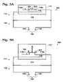
- FIGS. 4A and 4Bare plan views showing a first variation of a capacitively-loaded magnetic dipole antenna 400 with an adjustable quasi loop perimeter.
- the quasi loop 114has a first end 401 , a selectable second end 402 , and a selectable third end 404 .
- MEMS switch 406is a single-pole double-throw (SPDT) switch that either connects the quasi loop second end 402 in a first switch position, or connects the quasi loop third end 404 in a second switch position.
- the quasi loop 114has a longer length (perimeter) when connected in the first position to line 402 , than it does when connected to line end 404 .
- line segments 408 and 410are both aligned above line segment 412 .
- connectable line segments 408 and 410are shown respectively aligned “below” and “above” line segment 412 .
- the antennais not limited to merely double throw switches. Although not specifically shown, this antenna can be interfaced to a tunable balun, as described in the explanation of FIG. 2 .
- FIG. 5is a plan view showing a second variation of a capacitively-loaded magnetic dipole antenna with an adjustable quasi loop perimeter.
- the electric field bridge 112can be made tunable, as the bridges described in the explanation of FIGS. 1 and 2 .
- Large changes in the effective electric length of antenna 500can be enabled by changing the length of the quasi loop perimeter with elements 502 .
- the perimeter lengthis changed by creating a bridge between sections of the quasi loop 114 , using 502 a and 502 b to shorten the overall perimeter length. Note, when element 502 a is closed, element 502 b is closed. Likewise, when element 502 a is open, element 502 b is open.
- the perimeter lengthcan be changed using one of the approaches shown in FIG. 3A , 3 B, 4 A, or 4 B. Smaller adjustments in effective electric length can be obtained by tuning the electric field bridge 112 . Again, it should be understood that there are numerous arrangements of line segments alignments, switch positions, and bridge positions are possible. Further, although SPDT switches have been shown, the antenna 500 is not limited to merely double throw switches. Although not specifically shown, this antenna can be interfaced to a tunable balun, as described in the explanation of FIG. 2 .
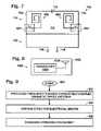
- FIG. 6is a plan view showing a third variation of a capacitively-loaded magnetic dipole antenna 600 with a selectable quasi loop perimeter.
- the capacitively-loaded magnetic dipole radiator 110includes a first (large) quasi loop 114 a , which is formed by closing switches 603 .
- Bridge 112 ais used when quasi loop 114 a is selected.
- a second (smaller) quasi loop 114 bis formed by opening switches 603 .
- bridge 112 bis used.
- Two SPDT switcheseither connect to the large loop or to a smaller loop.
- the small loophas the same general characteristics as the large loop. Regardless of which quasi loop is selected, the design remains quasi symmetrical.
- the electric field bridges 112 a and 112 bcan either be a fixed value or tunable as described in the explanation of FIGS. 1 and 2 .
- this antennacan be interfaced to a tunable balun, as described in the explanation of FIG. 2 .
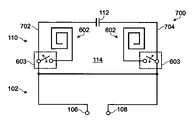
- FIG. 7is a plan view showing a fourth variation of a capacitively-loaded magnetic dipole antenna 700 with an adjustable quasi loop perimeter.
- the capacitively-loaded magnetic dipole radiator 110includes a quasi loop 114 with a plurality of selectable connectable auxiliary loop sections 600 . As shown, there are two auxiliary loop sections 602 selectively connectable using switch elements 603 .
- auxiliary loop sections 602can be placed either inside (as shown) or outside the quasi loop 114 , or both inside and outside.
- the auxiliary loop section 602may also be connected to other sides of the quasi loop 114 , besides the sides 702 and 704 shown in the figure.
- the electric field bridge 112can either be a fixed value or tunable as described in the explanation of FIGS. 1 and 2 .
- the auxiliary loop sections 602can be connected with MEMS or semiconductor switches, although the antenna is not limited to any particular switch technology. Although not specifically shown, this antenna can be interfaced to a tunable balun, as described in the explanation of FIG. 2 .
- FIG. 8is a schematic block diagram of a wireless telephone communications device with a frequency-tunable capacitively-loaded magnetic dipole antenna.
- the device 1000comprises a housing 1002 and a telephone transceiver 1004 embedded in the housing 1002 .
- a balanced feed capacitively-loaded magnetic dipole antenna 1006is embedded in the housing 1002 , and has a radiator with tunable effective electrical length.
- the effective electrical length of the radiatorcan be varied by using a tunable electric field bridge, an adjustable quasi loop perimeter, or an adjustable electric field bridge in combination with an adjustable perimeter.
- the capacitively-loaded magnetic dipole antenna 1006has a radiation efficiency that is insensitive to the proximity of the placement of a user's hand on the housing 1002 .
- the inventionis not limited to any particular communication format, i.e., the format may be Code Division Multiple Access (CDMA), Global System for Mobile Communications (GSM), or Universal Mobile Telecommunications System (UMTS). Neither is the device 1000 limited to any particular range of frequencies. Details of antenna variations are provided in the explanations of FIGS. 1 through 7 , above, and will not be repeated in the interests of brevity. Note, the invention is also applicable to other portable wireless devices, such as two-way radios, GPS receivers, Wireless Local Area Network (WLAN) transceivers, to name a few of examples.
- WLANWireless Local Area Network
- Balanced antennasdo not make use of the ground plane in order to radiate. This means that a balanced antenna can be located in a very thin wireless device, without detrimental affecting radiation performance. In fact, the antenna can be located within about 2 to 3 mm of a groundplane with no noticeable effect upon performance. The antenna is also less sensitive to currents on the ground plane, such as noise currents, or currents that are related to Specific Absorption Rate (SAR). Since the antenna can be made coplanar, it can be realized on a flex film, for example, at a very low cost.
- SARSpecific Absorption Rate
- FIG. 9is a flowchart illustrating a method for frequency tuning a capacitively-coupled magnetic dipole antenna. Although the method is depicted as a sequence of numbered steps for clarity, no order need be inferred from the numbering. It should be understood that some of these steps may be performed in parallel, or performed without the requirement of maintaining a strict order of sequence.
- the methodstarts at Step 900 .
- Step 902provides a capacitively-loaded magnetic dipole antenna with a transformer loop having a balanced feed interface, and a capacitively-loaded magnetic dipole radiator connected to the transformer loop, having an effective electrical length (see FIGS. 1-7 , and their explanations above).
- Step 904varies the effective electrical length of the radiator.
- Step 906changes the antenna operating frequency in response to varying the effective electrical length of the radiator.
- Step 902provides a capacitively-loaded magnetic dipole radiator with an electric field bridge. Then, Step 904 varies the effective electrical length of the radiator by varying the electric field across the electric field bridge. In another aspect, Step 902 provides a capacitively-loaded magnetic dipole radiator having a quasi loop with an adjustable perimeter. Then, Step 904 varies the effective electrical length of the radiator by varying the quasi loop perimeter. In certain embodiments, Step 904 varies the effective electric length is response to both varying the quasi loop perimeter and the field across the electric field bridge.
- a balanced feed, frequency-tunable capacitively-loaded magnetic dipole antennahas been provided.
- Some specific examples of loop shapes, loop orientations, bridge and quasi loop sections, physical implementations, and useshave been given to clarify the invention. However, the invention is not limited to merely these examples. Other variations and embodiments of the invention will occur to those skilled in the art.
Landscapes
- Engineering & Computer Science (AREA)
- Computer Networks & Wireless Communication (AREA)
- Details Of Aerials (AREA)
- Support Of Aerials (AREA)
Abstract
Description
Claims (20)
Priority Applications (2)
| Application Number | Priority Date | Filing Date | Title |
|---|---|---|---|
| US11/339,926US7408517B1 (en) | 2004-09-14 | 2006-01-25 | Tunable capacitively-loaded magnetic dipole antenna |
| US11/686,720US7876270B2 (en) | 2004-09-14 | 2007-03-15 | Modem card with balanced antenna |
Applications Claiming Priority (2)
| Application Number | Priority Date | Filing Date | Title |
|---|---|---|---|
| US10/940,935US7239290B2 (en) | 2004-09-14 | 2004-09-14 | Systems and methods for a capacitively-loaded loop antenna |
| US11/339,926US7408517B1 (en) | 2004-09-14 | 2006-01-25 | Tunable capacitively-loaded magnetic dipole antenna |
Related Parent Applications (1)
| Application Number | Title | Priority Date | Filing Date |
|---|---|---|---|
| US10/940,935Continuation-In-PartUS7239290B2 (en) | 2004-09-14 | 2004-09-14 | Systems and methods for a capacitively-loaded loop antenna |
Related Child Applications (2)
| Application Number | Title | Priority Date | Filing Date |
|---|---|---|---|
| US10/940,935Continuation-In-PartUS7239290B2 (en) | 2004-09-14 | 2004-09-14 | Systems and methods for a capacitively-loaded loop antenna |
| US11/686,720Continuation-In-PartUS7876270B2 (en) | 2004-09-14 | 2007-03-15 | Modem card with balanced antenna |
Publications (1)
| Publication Number | Publication Date |
|---|---|
| US7408517B1true US7408517B1 (en) | 2008-08-05 |
Family
ID=39670780
Family Applications (1)
| Application Number | Title | Priority Date | Filing Date |
|---|---|---|---|
| US11/339,926Expired - Fee RelatedUS7408517B1 (en) | 2004-09-14 | 2006-01-25 | Tunable capacitively-loaded magnetic dipole antenna |
Country Status (1)
| Country | Link |
|---|---|
| US (1) | US7408517B1 (en) |
Cited By (21)
| Publication number | Priority date | Publication date | Assignee | Title |
|---|---|---|---|---|
| US20060084395A1 (en)* | 2004-10-18 | 2006-04-20 | Research In Motion Limited | Method of controlling a plurality of internal antennas in a mobile communication device |
| US20070152891A1 (en)* | 2004-09-14 | 2007-07-05 | Jorge Fabrega-Sanchez | Modem card with balanced antenna |
| US20080024381A1 (en)* | 2006-07-26 | 2008-01-31 | Lg Electronics Inc. | Antenna and mobile terminal |
| US20080158092A1 (en)* | 2006-12-27 | 2008-07-03 | Semiconductor Energy Laboratory Co., Ltd. | Antenna and semiconductor device having the same |
| US20090231220A1 (en)* | 2008-03-14 | 2009-09-17 | Qualcomm Incorporated | Adaptive tunable antennas for wireless devices |
| US20100103061A1 (en)* | 2008-10-23 | 2010-04-29 | City University Of Hong Kong | Unidirectional antenna comprising a dipole and a loop |
| US20110205028A1 (en)* | 2010-02-25 | 2011-08-25 | Stmicroelectronics S.R.L. | Electronic communications device with antenna and electromagnetic shield |
| WO2012006152A1 (en)* | 2010-07-06 | 2012-01-12 | Apple Inc. | Tunable antenna systems |
| WO2012092198A1 (en)* | 2010-12-28 | 2012-07-05 | Lockheed Martin Corporation | Safe area voltage and current interface |
| US20120217820A1 (en)* | 2009-07-06 | 2012-08-30 | Young Tack Hong | Wireless power transmission system and resonator for the system |
| US20120250199A1 (en)* | 2006-01-17 | 2012-10-04 | Broadcom Corporation | Power over ethernet electrostatic discharge protection circuit |
| US20130194139A1 (en)* | 2012-02-01 | 2013-08-01 | Joshua G. Nickel | Electronic device with calibrated tunable antenna |
| US8525745B2 (en) | 2010-10-25 | 2013-09-03 | Sensor Systems, Inc. | Fast, digital frequency tuning, winglet dipole antenna system |
| US20140015723A1 (en)* | 2012-07-10 | 2014-01-16 | Samsung Electronics Co., Ltd | Broadband variable antenna device and portable terminal having the same |
| WO2015089017A1 (en)* | 2013-12-09 | 2015-06-18 | Shure Acquisition Holdings, Inc. | Adaptive self-tunable antenna system and method |
| US9166279B2 (en) | 2011-03-07 | 2015-10-20 | Apple Inc. | Tunable antenna system with receiver diversity |
| US9190712B2 (en) | 2012-02-03 | 2015-11-17 | Apple Inc. | Tunable antenna system |
| US9246221B2 (en) | 2011-03-07 | 2016-01-26 | Apple Inc. | Tunable loop antennas |
| US9350069B2 (en) | 2012-01-04 | 2016-05-24 | Apple Inc. | Antenna with switchable inductor low-band tuning |
| CN113471671A (en)* | 2021-07-05 | 2021-10-01 | 安徽安努奇科技有限公司 | Antenna structure and communication equipment with adjustable electric length |
| US11404786B2 (en)* | 2019-07-03 | 2022-08-02 | City University Of Hong Kong | Planar complementary antenna and related antenna array |
Citations (22)
| Publication number | Priority date | Publication date | Assignee | Title |
|---|---|---|---|---|
| US3882506A (en) | 1974-02-20 | 1975-05-06 | Taiyo Musen Co Ltd | Antenna for direction finders with mast isolation |
| DE8814993U1 (en) | 1988-01-04 | 1989-03-02 | Oppermann, Richard, 7762 Ludwigshafen | Antenna unit consisting of antenna loop, capacitor and coupling |
| USH1571H (en) | 1994-06-29 | 1996-08-06 | Hansen; Peder M. | Dual-feed, dual-mode antenna for mono-directional pattern |
| US6144346A (en) | 1996-09-20 | 2000-11-07 | Robert Bosch Gmbh | Antenna arrangement |
| US6204817B1 (en) | 1998-09-28 | 2001-03-20 | Allgon Ab | Radio communication device and an antenna system |
| EP1134840A2 (en) | 2000-03-06 | 2001-09-19 | Horst Prof. Dr. Ziegler | Antenna |
| EP1217685A2 (en) | 2000-12-12 | 2002-06-26 | Matsushita Electric Industrial Co., Ltd. | Ring resonator and antenna |
| WO2002071536A1 (en) | 2001-03-02 | 2002-09-12 | Motorola, Inc., A Corporation Of The State Of Delaware | Parasitic antenna element and wireless communication device incorporating the same |
| US6456243B1 (en) | 2001-06-26 | 2002-09-24 | Ethertronics, Inc. | Multi frequency magnetic dipole antenna structures and methods of reusing the volume of an antenna |
| US6486848B1 (en) | 2001-08-24 | 2002-11-26 | Gregory Poilasne | Circular polarization antennas and methods |
| US6573867B1 (en) | 2002-02-15 | 2003-06-03 | Ethertronics, Inc. | Small embedded multi frequency antenna for portable wireless communications |
| US6593886B2 (en)* | 2001-01-02 | 2003-07-15 | Time Domain Corporation | Planar loop antenna |
| US6600450B1 (en) | 2002-03-05 | 2003-07-29 | Motorola, Inc. | Balanced multi-band antenna system |
| US6624795B2 (en)* | 2000-12-16 | 2003-09-23 | Koninklijke Philips Electronics N.V. | Antenna arrangement |
| US6675461B1 (en) | 2001-06-26 | 2004-01-13 | Ethertronics, Inc. | Method for manufacturing a magnetic dipole antenna |
| US6693599B1 (en) | 1999-04-16 | 2004-02-17 | National University Of Singapore | RF transponder |
| US6697025B2 (en) | 2000-07-19 | 2004-02-24 | Matsushita Electric Industrial Co., Ltd. | Antenna apparatus |
| US6765846B2 (en) | 2000-01-28 | 2004-07-20 | Matsushita Electric Industrial Co., Ltd. | Antenna apparatus and wristwatch radio communication device using same |
| US6958735B2 (en)* | 2003-07-08 | 2005-10-25 | Handelsman Dan G | Compact and efficient three dimensional antennas |
| US20060038730A1 (en) | 2004-08-19 | 2006-02-23 | Harris Corporation | Litzendraht loop antenna and associated methods |
| US20060079177A1 (en)* | 2002-12-26 | 2006-04-13 | Akihiko Okubora | Wireless communicatin antenna and wireless communication device |
| US7187332B2 (en)* | 2005-02-28 | 2007-03-06 | Research In Motion Limited | Mobile wireless communications device with human interface diversity antenna and related methods |
- 2006
- 2006-01-25USUS11/339,926patent/US7408517B1/ennot_activeExpired - Fee Related
Patent Citations (22)
| Publication number | Priority date | Publication date | Assignee | Title |
|---|---|---|---|---|
| US3882506A (en) | 1974-02-20 | 1975-05-06 | Taiyo Musen Co Ltd | Antenna for direction finders with mast isolation |
| DE8814993U1 (en) | 1988-01-04 | 1989-03-02 | Oppermann, Richard, 7762 Ludwigshafen | Antenna unit consisting of antenna loop, capacitor and coupling |
| USH1571H (en) | 1994-06-29 | 1996-08-06 | Hansen; Peder M. | Dual-feed, dual-mode antenna for mono-directional pattern |
| US6144346A (en) | 1996-09-20 | 2000-11-07 | Robert Bosch Gmbh | Antenna arrangement |
| US6204817B1 (en) | 1998-09-28 | 2001-03-20 | Allgon Ab | Radio communication device and an antenna system |
| US6693599B1 (en) | 1999-04-16 | 2004-02-17 | National University Of Singapore | RF transponder |
| US6765846B2 (en) | 2000-01-28 | 2004-07-20 | Matsushita Electric Industrial Co., Ltd. | Antenna apparatus and wristwatch radio communication device using same |
| EP1134840A2 (en) | 2000-03-06 | 2001-09-19 | Horst Prof. Dr. Ziegler | Antenna |
| US6697025B2 (en) | 2000-07-19 | 2004-02-24 | Matsushita Electric Industrial Co., Ltd. | Antenna apparatus |
| EP1217685A2 (en) | 2000-12-12 | 2002-06-26 | Matsushita Electric Industrial Co., Ltd. | Ring resonator and antenna |
| US6624795B2 (en)* | 2000-12-16 | 2003-09-23 | Koninklijke Philips Electronics N.V. | Antenna arrangement |
| US6593886B2 (en)* | 2001-01-02 | 2003-07-15 | Time Domain Corporation | Planar loop antenna |
| WO2002071536A1 (en) | 2001-03-02 | 2002-09-12 | Motorola, Inc., A Corporation Of The State Of Delaware | Parasitic antenna element and wireless communication device incorporating the same |
| US6456243B1 (en) | 2001-06-26 | 2002-09-24 | Ethertronics, Inc. | Multi frequency magnetic dipole antenna structures and methods of reusing the volume of an antenna |
| US6675461B1 (en) | 2001-06-26 | 2004-01-13 | Ethertronics, Inc. | Method for manufacturing a magnetic dipole antenna |
| US6486848B1 (en) | 2001-08-24 | 2002-11-26 | Gregory Poilasne | Circular polarization antennas and methods |
| US6573867B1 (en) | 2002-02-15 | 2003-06-03 | Ethertronics, Inc. | Small embedded multi frequency antenna for portable wireless communications |
| US6600450B1 (en) | 2002-03-05 | 2003-07-29 | Motorola, Inc. | Balanced multi-band antenna system |
| US20060079177A1 (en)* | 2002-12-26 | 2006-04-13 | Akihiko Okubora | Wireless communicatin antenna and wireless communication device |
| US6958735B2 (en)* | 2003-07-08 | 2005-10-25 | Handelsman Dan G | Compact and efficient three dimensional antennas |
| US20060038730A1 (en) | 2004-08-19 | 2006-02-23 | Harris Corporation | Litzendraht loop antenna and associated methods |
| US7187332B2 (en)* | 2005-02-28 | 2007-03-06 | Research In Motion Limited | Mobile wireless communications device with human interface diversity antenna and related methods |
Cited By (41)
| Publication number | Priority date | Publication date | Assignee | Title |
|---|---|---|---|---|
| US7876270B2 (en)* | 2004-09-14 | 2011-01-25 | Kyocera Corporation | Modem card with balanced antenna |
| US20070152891A1 (en)* | 2004-09-14 | 2007-07-05 | Jorge Fabrega-Sanchez | Modem card with balanced antenna |
| US20070222698A1 (en)* | 2004-09-14 | 2007-09-27 | Gregory Poilasne | Systems and methods for a capacitively-loaded loop antenna |
| US7760151B2 (en)* | 2004-09-14 | 2010-07-20 | Kyocera Corporation | Systems and methods for a capacitively-loaded loop antenna |
| US20060084395A1 (en)* | 2004-10-18 | 2006-04-20 | Research In Motion Limited | Method of controlling a plurality of internal antennas in a mobile communication device |
| US7627296B2 (en)* | 2004-10-18 | 2009-12-01 | Research In Motion Limited | Method of controlling a plurality of internal antennas in a mobile communication device |
| US20120250199A1 (en)* | 2006-01-17 | 2012-10-04 | Broadcom Corporation | Power over ethernet electrostatic discharge protection circuit |
| US20080024381A1 (en)* | 2006-07-26 | 2008-01-31 | Lg Electronics Inc. | Antenna and mobile terminal |
| US7868836B2 (en)* | 2006-07-26 | 2011-01-11 | Lg Electronics Inc. | Antenna and mobile terminal |
| US20080158092A1 (en)* | 2006-12-27 | 2008-07-03 | Semiconductor Energy Laboratory Co., Ltd. | Antenna and semiconductor device having the same |
| US8610632B2 (en) | 2008-03-14 | 2013-12-17 | Qualcomm Incorporated | Adaptive tunable antennas for wireless devices |
| US8614646B2 (en)* | 2008-03-14 | 2013-12-24 | Qualcomm Incorporated | Adaptive tunable antennas for wireless devices |
| US20090231220A1 (en)* | 2008-03-14 | 2009-09-17 | Qualcomm Incorporated | Adaptive tunable antennas for wireless devices |
| US8410982B2 (en)* | 2008-10-23 | 2013-04-02 | City University Of Hong Kong | Unidirectional antenna comprising a dipole and a loop |
| US20100103061A1 (en)* | 2008-10-23 | 2010-04-29 | City University Of Hong Kong | Unidirectional antenna comprising a dipole and a loop |
| US20120217820A1 (en)* | 2009-07-06 | 2012-08-30 | Young Tack Hong | Wireless power transmission system and resonator for the system |
| US9728837B2 (en) | 2010-02-25 | 2017-08-08 | Stmicroelectronics S.R.L. | Method and apparatus for tuning a resonant circuit using a laser |
| US20110205028A1 (en)* | 2010-02-25 | 2011-08-25 | Stmicroelectronics S.R.L. | Electronic communications device with antenna and electromagnetic shield |
| US9112263B2 (en) | 2010-02-25 | 2015-08-18 | Stmicroelectronics S.R.L. | Electronic communications device with antenna and electromagnetic shield |
| US10171125B2 (en) | 2010-07-06 | 2019-01-01 | Apple Inc. | Tunable antenna systems |
| WO2012006152A1 (en)* | 2010-07-06 | 2012-01-12 | Apple Inc. | Tunable antenna systems |
| US9893755B2 (en) | 2010-07-06 | 2018-02-13 | Apple Inc. | Tunable antenna systems |
| US9070969B2 (en) | 2010-07-06 | 2015-06-30 | Apple Inc. | Tunable antenna systems |
| US8525745B2 (en) | 2010-10-25 | 2013-09-03 | Sensor Systems, Inc. | Fast, digital frequency tuning, winglet dipole antenna system |
| US8351879B2 (en) | 2010-12-28 | 2013-01-08 | Lockheed Martin Corporation | Safe area voltage and current interface |
| WO2012092198A1 (en)* | 2010-12-28 | 2012-07-05 | Lockheed Martin Corporation | Safe area voltage and current interface |
| US9166279B2 (en) | 2011-03-07 | 2015-10-20 | Apple Inc. | Tunable antenna system with receiver diversity |
| US9246221B2 (en) | 2011-03-07 | 2016-01-26 | Apple Inc. | Tunable loop antennas |
| US9350069B2 (en) | 2012-01-04 | 2016-05-24 | Apple Inc. | Antenna with switchable inductor low-band tuning |
| US9270012B2 (en)* | 2012-02-01 | 2016-02-23 | Apple Inc. | Electronic device with calibrated tunable antenna |
| US20130194139A1 (en)* | 2012-02-01 | 2013-08-01 | Joshua G. Nickel | Electronic device with calibrated tunable antenna |
| US9190712B2 (en) | 2012-02-03 | 2015-11-17 | Apple Inc. | Tunable antenna system |
| US9640871B2 (en)* | 2012-07-10 | 2017-05-02 | Samsung Electronics Co., Ltd. | Broadband variable antenna device and portable terminal having the same |
| US20140015723A1 (en)* | 2012-07-10 | 2014-01-16 | Samsung Electronics Co., Ltd | Broadband variable antenna device and portable terminal having the same |
| WO2015089017A1 (en)* | 2013-12-09 | 2015-06-18 | Shure Acquisition Holdings, Inc. | Adaptive self-tunable antenna system and method |
| US9893715B2 (en) | 2013-12-09 | 2018-02-13 | Shure Acquisition Holdings, Inc. | Adaptive self-tunable antenna system and method |
| US10348272B2 (en) | 2013-12-09 | 2019-07-09 | Shure Acquisition Holdings, Inc. | Adaptive self-tunable antenna system and method |
| US11469740B2 (en) | 2013-12-09 | 2022-10-11 | Shure Acquisition Holdings, Inc. | Adaptive self-tunable antenna system and method |
| US11404786B2 (en)* | 2019-07-03 | 2022-08-02 | City University Of Hong Kong | Planar complementary antenna and related antenna array |
| CN113471671A (en)* | 2021-07-05 | 2021-10-01 | 安徽安努奇科技有限公司 | Antenna structure and communication equipment with adjustable electric length |
| CN113471671B (en)* | 2021-07-05 | 2023-08-25 | 安徽安努奇科技有限公司 | Antenna structure with adjustable electric length and communication equipment |
Similar Documents
| Publication | Publication Date | Title |
|---|---|---|
| US7408517B1 (en) | Tunable capacitively-loaded magnetic dipole antenna | |
| US6166694A (en) | Printed twin spiral dual band antenna | |
| US7760151B2 (en) | Systems and methods for a capacitively-loaded loop antenna | |
| US6980154B2 (en) | Planar inverted F antennas including current nulls between feed and ground couplings and related communications devices | |
| KR100612798B1 (en) | Miniature Printed Spiral Antenna for Mobile Terminal | |
| US7345634B2 (en) | Planar inverted “F” antenna and method of tuning same | |
| US6515625B1 (en) | Antenna | |
| US9793597B2 (en) | Antenna with active elements | |
| KR100993439B1 (en) | Antenna device and radio communication device | |
| US7834813B2 (en) | Methods and apparatuses for adaptively controlling antenna parameters to enhance efficiency and maintain antenna size compactness | |
| US6765536B2 (en) | Antenna with variably tuned parasitic element | |
| US20020126052A1 (en) | Antenna arrangement | |
| US20060132360A1 (en) | Method and apparatus for adaptively controlling antenna parameters to enhance efficiency and maintain antenna size compactness | |
| US20140015719A1 (en) | Switched antenna apparatus and methods | |
| JPH10284919A (en) | Antenna system | |
| US7427965B2 (en) | Multiple band capacitively-loaded loop antenna | |
| KR20070052292A (en) | Antenna device and portable wireless communication device including such antenna device | |
| US7274338B2 (en) | Meander line capacitively-loaded magnetic dipole antenna | |
| US7928914B2 (en) | Multi-frequency conductive-strip antenna system | |
| US8421695B2 (en) | Multi-frequency, noise optimized active antenna | |
| KR20070051292A (en) | Antenna device and portable wireless communication device including such antenna device |
Legal Events
| Date | Code | Title | Description |
|---|---|---|---|
| AS | Assignment | Owner name:KYOCERA WIRELESS CORP., CALIFORNIA Free format text:ASSIGNMENT OF ASSIGNORS INTEREST;ASSIGNORS:POILASNE, GREGORY;FABREGA, JORDI;HWANG, HUAN-SHENG;AND OTHERS;REEL/FRAME:017516/0216;SIGNING DATES FROM 20060123 TO 20060124 | |
| STCF | Information on status: patent grant | Free format text:PATENTED CASE | |
| FEPP | Fee payment procedure | Free format text:PAYOR NUMBER ASSIGNED (ORIGINAL EVENT CODE: ASPN); ENTITY STATUS OF PATENT OWNER: LARGE ENTITY | |
| AS | Assignment | Owner name:KYOCERA CORPORATION,JAPAN Free format text:ASSIGNMENT OF ASSIGNORS INTEREST;ASSIGNOR:KYOCERA WIRELESS CORP.;REEL/FRAME:024170/0005 Effective date:20100326 Owner name:KYOCERA CORPORATION, JAPAN Free format text:ASSIGNMENT OF ASSIGNORS INTEREST;ASSIGNOR:KYOCERA WIRELESS CORP.;REEL/FRAME:024170/0005 Effective date:20100326 | |
| FEPP | Fee payment procedure | Free format text:PAYER NUMBER DE-ASSIGNED (ORIGINAL EVENT CODE: RMPN); ENTITY STATUS OF PATENT OWNER: LARGE ENTITY Free format text:PAYOR NUMBER ASSIGNED (ORIGINAL EVENT CODE: ASPN); ENTITY STATUS OF PATENT OWNER: LARGE ENTITY | |
| FPAY | Fee payment | Year of fee payment:4 | |
| FPAY | Fee payment | Year of fee payment:8 | |
| FEPP | Fee payment procedure | Free format text:MAINTENANCE FEE REMINDER MAILED (ORIGINAL EVENT CODE: REM.); ENTITY STATUS OF PATENT OWNER: LARGE ENTITY | |
| LAPS | Lapse for failure to pay maintenance fees | Free format text:PATENT EXPIRED FOR FAILURE TO PAY MAINTENANCE FEES (ORIGINAL EVENT CODE: EXP.); ENTITY STATUS OF PATENT OWNER: LARGE ENTITY | |
| STCH | Information on status: patent discontinuation | Free format text:PATENT EXPIRED DUE TO NONPAYMENT OF MAINTENANCE FEES UNDER 37 CFR 1.362 | |
| FP | Lapsed due to failure to pay maintenance fee | Effective date:20200805 |