US7407494B2 - Device for delivering medicament - Google Patents
Device for delivering medicamentDownload PDFInfo
- Publication number
- US7407494B2 US7407494B2US11/045,379US4537905AUS7407494B2US 7407494 B2US7407494 B2US 7407494B2US 4537905 AUS4537905 AUS 4537905AUS 7407494 B2US7407494 B2US 7407494B2
- Authority
- US
- United States
- Prior art keywords
- piston
- distance
- holding
- activator
- dose
- Prior art date
- Legal status (The legal status is an assumption and is not a legal conclusion. Google has not performed a legal analysis and makes no representation as to the accuracy of the status listed.)
- Expired - Lifetime, expires
Links
Images


Classifications
- A—HUMAN NECESSITIES
- A61—MEDICAL OR VETERINARY SCIENCE; HYGIENE
- A61M—DEVICES FOR INTRODUCING MEDIA INTO, OR ONTO, THE BODY; DEVICES FOR TRANSDUCING BODY MEDIA OR FOR TAKING MEDIA FROM THE BODY; DEVICES FOR PRODUCING OR ENDING SLEEP OR STUPOR
- A61M5/00—Devices for bringing media into the body in a subcutaneous, intra-vascular or intramuscular way; Accessories therefor, e.g. filling or cleaning devices, arm-rests
- A61M5/178—Syringes
- A61M5/31—Details
- A61M5/315—Pistons; Piston-rods; Guiding, blocking or restricting the movement of the rod or piston; Appliances on the rod for facilitating dosing ; Dosing mechanisms
- A61M5/31501—Means for blocking or restricting the movement of the rod or piston
- A—HUMAN NECESSITIES
- A61—MEDICAL OR VETERINARY SCIENCE; HYGIENE
- A61M—DEVICES FOR INTRODUCING MEDIA INTO, OR ONTO, THE BODY; DEVICES FOR TRANSDUCING BODY MEDIA OR FOR TAKING MEDIA FROM THE BODY; DEVICES FOR PRODUCING OR ENDING SLEEP OR STUPOR
- A61M5/00—Devices for bringing media into the body in a subcutaneous, intra-vascular or intramuscular way; Accessories therefor, e.g. filling or cleaning devices, arm-rests
- A61M5/178—Syringes
- A61M5/20—Automatic syringes, e.g. with automatically actuated piston rod, with automatic needle injection, filling automatically
- A61M5/2066—Automatic syringes, e.g. with automatically actuated piston rod, with automatic needle injection, filling automatically comprising means for injection of two or more media, e.g. by mixing
- A—HUMAN NECESSITIES
- A61—MEDICAL OR VETERINARY SCIENCE; HYGIENE
- A61M—DEVICES FOR INTRODUCING MEDIA INTO, OR ONTO, THE BODY; DEVICES FOR TRANSDUCING BODY MEDIA OR FOR TAKING MEDIA FROM THE BODY; DEVICES FOR PRODUCING OR ENDING SLEEP OR STUPOR
- A61M5/00—Devices for bringing media into the body in a subcutaneous, intra-vascular or intramuscular way; Accessories therefor, e.g. filling or cleaning devices, arm-rests
- A61M5/178—Syringes
- A61M5/20—Automatic syringes, e.g. with automatically actuated piston rod, with automatic needle injection, filling automatically
- A61M2005/2006—Having specific accessories
- A61M2005/2013—Having specific accessories triggering of discharging means by contact of injector with patient body
- A—HUMAN NECESSITIES
- A61—MEDICAL OR VETERINARY SCIENCE; HYGIENE
- A61M—DEVICES FOR INTRODUCING MEDIA INTO, OR ONTO, THE BODY; DEVICES FOR TRANSDUCING BODY MEDIA OR FOR TAKING MEDIA FROM THE BODY; DEVICES FOR PRODUCING OR ENDING SLEEP OR STUPOR
- A61M5/00—Devices for bringing media into the body in a subcutaneous, intra-vascular or intramuscular way; Accessories therefor, e.g. filling or cleaning devices, arm-rests
- A61M5/178—Syringes
- A61M5/20—Automatic syringes, e.g. with automatically actuated piston rod, with automatic needle injection, filling automatically
- A61M5/2033—Spring-loaded one-shot injectors with or without automatic needle insertion
- A—HUMAN NECESSITIES
- A61—MEDICAL OR VETERINARY SCIENCE; HYGIENE
- A61M—DEVICES FOR INTRODUCING MEDIA INTO, OR ONTO, THE BODY; DEVICES FOR TRANSDUCING BODY MEDIA OR FOR TAKING MEDIA FROM THE BODY; DEVICES FOR PRODUCING OR ENDING SLEEP OR STUPOR
- A61M5/00—Devices for bringing media into the body in a subcutaneous, intra-vascular or intramuscular way; Accessories therefor, e.g. filling or cleaning devices, arm-rests
- A61M5/178—Syringes
- A61M5/24—Ampoule syringes, i.e. syringes with needle for use in combination with replaceable ampoules or carpules, e.g. automatic
- A61M5/2448—Ampoule syringes, i.e. syringes with needle for use in combination with replaceable ampoules or carpules, e.g. automatic comprising means for injection of two or more media, e.g. by mixing
- A—HUMAN NECESSITIES
- A61—MEDICAL OR VETERINARY SCIENCE; HYGIENE
- A61M—DEVICES FOR INTRODUCING MEDIA INTO, OR ONTO, THE BODY; DEVICES FOR TRANSDUCING BODY MEDIA OR FOR TAKING MEDIA FROM THE BODY; DEVICES FOR PRODUCING OR ENDING SLEEP OR STUPOR
- A61M5/00—Devices for bringing media into the body in a subcutaneous, intra-vascular or intramuscular way; Accessories therefor, e.g. filling or cleaning devices, arm-rests
- A61M5/178—Syringes
- A61M5/31—Details
- A61M5/3146—Priming, e.g. purging, reducing backlash or clearance
- A—HUMAN NECESSITIES
- A61—MEDICAL OR VETERINARY SCIENCE; HYGIENE
- A61M—DEVICES FOR INTRODUCING MEDIA INTO, OR ONTO, THE BODY; DEVICES FOR TRANSDUCING BODY MEDIA OR FOR TAKING MEDIA FROM THE BODY; DEVICES FOR PRODUCING OR ENDING SLEEP OR STUPOR
- A61M5/00—Devices for bringing media into the body in a subcutaneous, intra-vascular or intramuscular way; Accessories therefor, e.g. filling or cleaning devices, arm-rests
- A61M5/178—Syringes
- A61M5/31—Details
- A61M5/315—Pistons; Piston-rods; Guiding, blocking or restricting the movement of the rod or piston; Appliances on the rod for facilitating dosing ; Dosing mechanisms
- A61M5/31533—Dosing mechanisms, i.e. setting a dose
- A61M5/31535—Means improving security or handling thereof, e.g. blocking means, means preventing insufficient dosing, means allowing correction of overset dose
- A61M5/31536—Blocking means to immobilize a selected dose, e.g. to administer equal doses
- A61M5/31538—Permanent blocking, e.g. by medical personnel
Definitions
- the present inventionrelates to a device for delivering medicament to a patient and in particular in connection with medicament that needs to be pre-treated, mixed, before delivery.
- the medicamentmost types are packaged in cartridges, ampoules or syringes containing a ready-to-use liquid-state medicament, where the medicament is dissolved or suspended with the liquid, where they could be stored for a long time before use.
- some types of medicamentcannot be pre-mixed because the medicament becomes degraded and looses its effect rather quickly when mixed with the liquid. Solutions can also have a limited effective time span.
- the user, patient or nurse/physicianhas to perform the mixing within a limited time prior to the delivery. In the case of injecting the medicament, this is usually done such that the medicament in powder or liquid form is arranged in a container, often a small vial.
- cartridges, ampoules or syringeswhich contain two chambers, each containing a part of the medicament solution, which, when mixed, forms the medicament to be delivered.
- the two chambersare sealed off when stored in order that the medicament solution does not become degraded.
- passagesare opened between the chambers, usually by depressing the stopper and in turn the divider of the syringe somewhat. The passages allow the mixing of the parts and the medicament is ready for delivery.
- these dual chamber cartridges, syringes or ampouleshave only been used with ordinary type, manually handled devices. For certain applications and medicaments however, it would be advantageous to use a device in combination with these dual chamber solutions in an easy and user-friendly way in order to obtain the mixing before delivery.
- the aim of the present inventionis to provide a medicament delivery device which facilitates the use of plurality-chamber cartridges, syringes, ampoules and other containers.
- a devicecomprising a main housing, a container including at least two compartments, wherein each compartment contains at least one component of the medicament solution to be injected, and arranged to be connected to a patient delivery means, a longitudinally movable piston and a spring arrangement acting on said piston and capable of exerting a force on said components, a holding means arranged and capable of holding said piston in a force-loaded state, and at least one activator means capable of releasing said piston, characterised in that it further comprises stop means capable of stopping the movement of said piston when it has moved a certain first distance after one activation of the at least one activator means, wherein the force from the piston/spring arrangement and the movement causes the compartments to communicate with each other and the components to mix, and wherein, upon a subsequent activation of said at least one activator means, the piston moves a certain second distance, wherein the force from the piston/spring arrangement and the movement causes the mixed components to be ejected through the patient delivery means.
- itcomprises means for adjusting the second distance in order to adjust the second and subsequent distance in order for doses to be delivered.
- the advantages with the present inventionare several compared to the state of the art. Because the device is capable of stopping the piston acting on the stopper of the container or syringe with two or more chambers, the mixing can be performed in a very simple and yet reliable way and without the need of reloading the device for subsequent injections.
- the piston/spring arrangementhas such a force and travel that both the mixing movement and the subsequent injections movements can be obtained.
- the locking of the piston after the mixingmay be obtained in many suitable ways and the release of the piston after the mixing procedure may be performed manually by pressing a button or the like or be performed automatically when, in the case of injectors, pressing the injector against the delivery site.
- the device of the present inventionis very easy to handle due to the dose adjusting capabilities presented.
- the patientmerely sets the device to deliver the proper dose. It is of course possible with the present device to have a fixed dose that cannot be altered, which may be advantageous if for example children are to use it, or if it is desired to have a very easy-to-use functionality.
- the injectorWhen used as an injector, the injector preferably is provided with a needle shield that is capable of covering the needle after use, which needle shield is locked in that position. This prevents accidental needle-sticks on contaminated needles from occurring.
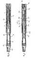
- FIG. 1 ais a longitudinal cross-sectional view of a first embodiment according to the invention in a state when it is delivered to the patient,
- FIGS. 1 b - 1 dare detailed views of certain components of the device of FIG. 1 a
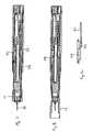
- FIG. 2is a view corresponding to FIG. 1 where a mixing has been performed
- FIG. 3is a view corresponding to FIG. 1 where a priming has been performed
- FIG. 4is a view corresponding to FIG. 1 where a needle cover is removed and a tool is applied for activating the device
- FIG. 5is a view corresponding to FIG. 1 where the dose is activated and a needle cover has been pushed forward
- FIG. 6is a view corresponding to FIG. 1 where a dose has been set
- FIG. 7is a view corresponding to FIG. 1 where the injection is activated
- FIG. 8is a view corresponding to FIG. 1 after completed injection and withdrawal of the device
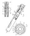
- FIG. 9 ais a somewhat modified design of the embodiment according to FIGS. 1-8 .
- FIG. 9 bis a detailed view taken along the plane IXb-IXb in FIG. 9 a,
- FIG. 9 cis a cross-sectional view taken along the line IXc-IXc in FIG. 9 b,
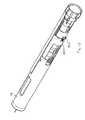
- FIGS. 10-15show the embodiment according to FIG. 9 a , in different modes of operation
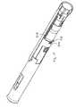
- FIGS. 16 a - eare side-views of a second embodiment of the present invention in different steps of operation
- FIG. 17is a side-view of the second embodiment of the invention.
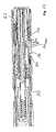
- FIG. 18is a partial view in cross-section of the upper end of the auto-injector according to the invention with actuating means in a non-activated mixing position
- FIG. 19is a view corresponding to FIG. 18 where mixing has been performed but an activation button is still depressed
- FIG. 20is a view corresponding to FIG. 18 with a dose set
- FIG. 21is a view corresponding to FIG. 18 during injection.
- FIG. 22is a view when the injector is withdrawn and the needle cover is pushed out around the needle and locked.
- the injectorcomprises a main rear generally tubular housing 10 and a main front tubular housing 12 .
- the front housingis surrounded by a generally tubular needle shield 14 slidable in relation to the front housing but held in a fixed rotational position by longitudinal ridges on the inner surface of the needle shield and corresponding grooves 16 on the outer surface of the front housing, FIG. 1 b .
- the needle shieldis further provided with windows 18 .
- a syringe or cartridge 20 with two chambers 22 , 24is arranged inside the lower housing.
- a neck portion 26is attached with two tongues 28 , one shown with broken lines in FIG. 1 b , extending into the front housing 12 , which tongues are arranged with outwardly directed protrusions 30 , which in turn fit into recesses 32 arranged along a certain sector of the inner circumference of the lower housing.
- the neck portion 26further comprises a plate 34 where the outer edge of the plate fits into a groove arranged on the ridges of the inner surface of the needle shield 14 and where the edge of the plate is arranged with cut-outs 36 corresponding in size to the grooves on the outer surface of the front main housing.
- a needle 38can be attached to the neck portion in a manner which will be described below.
- the rear part of the front main housingis arranged with a wall 40 arranged with a central circular opening 42 having two opposite cut-outs 44 , FIG. 1 c .
- the upper part of the needle shieldis arranged with openings 46 .
- a generally tubular guide sleeve 48is slidably arranged and is provided with outwardly directed protrusions 50 , that are engaging the openings 46 of the needle shield 14 so as to form a fixed connection between the two parts.
- dose setting sleeveInside the guide sleeve a further sleeve 52 , hereafter named dose setting sleeve, is arranged. At its front end the dose setting sleeve is arranged with longitudinal grooves 54 , FIG. 1 d . At its upper end the sleeve is attached to, or made in one piece with, a dose setting knob 56 , which knob extends out of the main rear housing 10 , and is preferably provided with a grip means like grooves or protrusions as well as dose indication means, which will be explained later.
- a piston 58is arranged which extends through the central opening 42 of the wall 40 .
- the pistonis attached to the dose setting knob 56 .
- the pistonis arranged with external, double helix threads, ie. one left-handed thread and one right-handed thread.
- the pistonis further arranged with longitudinally extending ribs 60 , FIG. 1 c .
- Two nuts 62 , 64are threaded onto the piston 58 , hereafter named front nut 62 and rear nut 64 , where one nut has right-handed threads and one nut has left-handed threads.
- the nutsare arranged inside the dose setting sleeve 52 such that they are prevented from rotating by the longitudinal grooves 54 of the dose setting sleeve 52 and ledges 66 on the outer surfaces of the nuts 62 , 64 that fit into the grooves.
- a spring(not shown) is arranged between an end wall 68 of the piston and an abutment wall 70 of the dose setting knob 56 .
- a guide rod 72 for the springis attached to the dose adjusting knob.
- the device according to the first embodimentis intended to function as follows.
- the deviceis delivered to the patient as seen in FIG. 1 .
- the two nuts 62 , 64have been threaded onto the piston 58 with a certain distance D from the wall 40 .
- the nutsare held in that position by the ledges 66 of the nuts fitting into the longitudinal grooves 54 of the dose adjusting sleeve, wherein the piston rests against the rear end of the medicament cartridge 16 and the spring is tensioned.
- the pistonis prevented from moving forward in that the front end of the longitudinal ribs 60 is abutting the wall 40 .
- the patientturns the dose setting knob 56 to a position “Mix” indicated on the outside of the upper main housing 10 .
- the turningcauses the piston 58 attached to the dose setting knob to be turned until its longitudinal ribs 60 are in register with the cut-outs 44 of the wall 40 whereby the piston moves forward due to the force of the spring, FIG. 2 .
- Thiscauses the stopper and divider of the cartridge 20 to move forward whereby passages are opened between the two compartments 22 , 24 and the medicament component or components form is mixed with the liquid.
- the mixingcan be viewed through the windows 18 . Due to the built up pressure of the mixed medicament and gas or air the piston is prevented from moving further.
- the initial position of the nuts on the piston and the length of the pistonare chosen such that after the mixing the nuts are positioned a certain distance C from the wall 40 , FIG. 2 and also to obtain a proper mixing of the medicament.
- a needle 38 with a needle cover 80which needle cover preferably comprises an outer needle cover 80 a and an inner needle cover 80 b is attached onto the neck portion 26 of the main front housing, FIG. 3 , whereby the rear end of the needle penetrates an elastic seal at the front end of the cartridge. Due to the pressure of the medicament in the cartridge, gas or air and a small amount of liquid is ejected from the compartment, and is collected and seen in the outer needle cover 80 a , causing a priming of the device and resetting of the system in that the ejection of the medicament causes the piston 58 to move forward until the front nut 62 abuts the wall 40 and the rear nut 64 to be in contact with the front nut.
- the length of the dose setting sleeve 52is such that when the front nut 62 is in contact with the wall 40 the ledges 66 of the front nut have moved out of the longitudinal grooves 54 of the dose setting sleeve 52 .
- the deviceis now calibrated and reset in that the cartridge is ready for injection and the nuts are pushed together by the full force of the spring, thereby eliminating all play and other mechanical deficiencies of the mechanism.
- the outer needle cover 80 ais now removed.
- a tool 74having a generally tubular end form designed to fit into the end of the needle shield 14 , and further having protrusions at its end surface fitting into corresponding recesses in the plate 34 of the neck portion 26 , is inserted into the end of the needle shield and turned, FIG. 11 .
- Thiscauses the plate 34 of the neck portion to be turned until its cut-outs 36 are in register with the groove 16 of the front housing, releasing the needle shield 14 and bringing it forward, surrounding the needle 38 , by a spring (not shown), FIG. 5 .
- the toolWhen the tool is removed, it brings with it the inner needle cover.
- the dosecan now be set by turning the dose setting knob so that a dose quantity indication for the chosen dose on the outside of the main upper housing is in register with an indication mark on the knob.
- the turning of the knobcauses the dose setting sleeve also to turn.
- the inner end of the dose setting sleeve 52does not reach all the way to the wall 40 thereby creating a distance E, between the wall 40 and the end of the sleeve, which distance is somewhat larger than the width of the front nut 62 , so that the front nut is no longer held by the sleeve.
- the front nutis prevented from rotation by inwardly extending protrusions on the rear part of the needle shield.
- the turning of the knob 56 and the sleeve 52causes the rear nut 64 to turn because of its ledges positioned in the groove and to move along the piston due to its threads in engagement with the threads of the piston. This creates a distance F between the nuts, FIG. 6 .
- the deviceis now ready for injection.
- the needle shield 14is pressed against the injection site and the needle 38 is pushed into the patient, FIG. 7 .
- the inwardly directed protrusions of the rear end of the needle shield 14are moved out of engagement with the ledges of the front nut 62 , which thus is released and will rotate due to the contact with the wall 40 and due to the force on the threaded piston 58 from the spring, whereby the piston will move into the cartridge and inject the medicament through the needle.
- the movement of the pistonis stopped when the rear nut comes in contact with the front nut and the injection is completed. It is then to be understood that the distance F corresponds to a certain volume of medicament that is to be injected.
- the devicecan now be removed from the injection site, FIG. 8 , whereby the needle shield 14 and the guide sleeve 48 are pushed forward by a spring (not shown) in order to cover the needle and locks in that position by resilient arms 82 arranged at the rear end of the guide sleeve 48 that pass the front end of the dose setting sleeve 52 when the needle shield has reached its most extended position, whereby the arms will move inwards and rest on the front end of the dose setting sleeve, FIG. 8 a.
- FIGS. 9-22A variant of the design according to FIGS. 1-8 is shown in FIGS. 9-22 .
- a sleeve 200is arranged and attached to the dose setting knob 56 , having a particular configuration, FIG. 9 .
- inwardly gripping hooks 204 arranged on the inner upper surface of a shield link member 206are in contact with an upper ledge 203 , FIG. 11 , arranged on the outer surface of the sleeve, thereby preventing any axial movement between the sleeve and the shield link member.
- the knob 56is turned so that a mix position is indicated, FIG. 11 .
- the turning of the knobcauses the piston 58 attached to the dose setting knob to be turned until its longitudinal ribs 60 are in register with the cut-outs 44 of the wall 40 whereby the piston moves forward due to the force of the spring and the mixing is performed, in the same manner as with the previous embodiment.
- the turning of the dose setting knobcauses the dose setting sleeve 52 , attached to the dose setting knob, to be turned.
- the turning of the dose setting sleeveturns the nuts 62 , 64 because of their connection via the ledges 66 fitting into the grooves 54 of the dose setting sleeve.
- the front nut 62is arranged with Y-shaped fork-like protrusions 203 that are in contact with ribs 205 arranged on the inner surface of the sleeve 200 , which connection causes the sleeve 200 to be turned so that longitudinal grooves 202 on the outer surface of the sleeve is aligned with the hooks 204 .
- the step of attaching the needle and priming and resetting the deviceis also performed in the above described manner.
- the outer needle cover 80 ais now removed and the tool 74 is inserted into the end of the needle shield and turned as described above for preparing the device for injecting a dose.
- the inner shieldis also removed.
- the dose setting knob 56is turned again, FIG. 12 , whereby the nuts are separated in the same manner as in the previous embodiment because the dose setting sleeve will rotate the rear nut so that a certain distance is created between them.
- the front end of the injectoris pressed against the injection site whereby the needle penetrates the skin.
- the needle shield 14is pushed back, FIG. 13 , whereby the hooks 204 of the needle shield link slide back in the grooves 202 until they are in their almost rearward position. At this position the grooves have terminated, FIG. 13 .
- the injectoris removed from the injection site, FIG. 15 , whereby the needle shield spring 210 forces the needle shield forward, whereby the hooks 204 of the needle shield link to slide on the outer surface of the sleeve 200 until the needle shield is in its foremost position. In that position the hooks are placed in a front groove 212 arranged on the outside of the sleeve 200 , whereby the rear surfaces of the hooks engage with the rear surface of the front groove, which in turn locks the needle shield from moving backwards.
- FIGS. 16 to 22A second embodiment of the present invention will now be described in connection with FIGS. 16 to 22 . It includes a main rear generally tubular housing 110 and a main front generally tubular housing 112 .
- the main front housingis surrounded by a generally tubular needle shield 114 arranged to be slidable along the lower housing.
- the needle shieldis arranged with windows 115 .
- a syringe or cartridge 116Inside the main front housing a syringe or cartridge 116 with two chambers, 118 , 120 , is arranged. In the non-affected state the chambers each contain a component of the medicament solution to be injected, and the chambers are sealed off from each other.
- the front end of the front main housingis arranged with a neck portion 121 , onto which a needle may be attached.
- a needle shield holder 122 in the form of a generally tubular shapeis arranged inside the rear main housing 110 . It is connected to the needle shield holder 122 by protrusions 124 fitting into recesses 126 in the rear part of the needle shield, to the right in the figures.
- the rear part, also to the right, of the needle shield holderis arranged with inwardly directed protrusions 128 .
- a spring 129is arranged between a ledge 131 arranged on the inside of the main upper housing 110 and the upper end surface of the needle shield holder.
- a piston 130extends through the centre of the rear main housing with one end abutting the inner end of the syringe 116 .
- the pistonis on its outer surface arranged with protrusions 132 , 134 at certain locations along the piston.
- a dose actuation spring 136is arranged, which is guided by a guide rod 138 at the upper end of the rear main housing.
- a guide sleeve 140Surrounding the piston/spring assembly is a guide sleeve 140 having an elongated groove in which a stop ledge 142 arranged at the upper end of the piston 130 can slide, the function of which will be explained below.
- An activator means 144is arranged at the rear main housing comprising an activation button 146 located at the rear end of the device.
- the activator meansfurther includes a sleeve-like part 148 surrounding the piston/spring assembly and the guide sleeve 140 .
- the activator sleeveis also arranged with a groove in the same manner as the guide sleeve 140 .
- a holding means 150is arranged abutting a dividing wall 152 in the front main housing at its upper end.
- the dividing wallis arranged with a through-hole, through which the piston 130 protrudes.
- the holding meansincludes a number of resiliently flexing tongues 154 which are pressed inwards, and contact the outer surface of the piston due to their inherent resilient properties.
- the activator meansfurther includes a deflecting means 156 arranged with to the left pointing protrusions 158 with inclined surfaces, where the lower part of the inclined surfaces are in contact with the outer ends of the resilient tongues 154 .
- a dosage adjusting means 160is arranged outside the actuator sleeve. It comprises an upper (to the right) adjusting part 162 which protrudes outside the upper end of the rear main housing 110 and has grip ribs or the like as well as indications for different adjusting positions, such as locked position, mixing, dose quantity and the like, as will be explained.
- the outer surface adjacent the adjusting partis provided with an indication, like an arrow, to function in conjunction with the adjusting indications.
- the dosage adjusting meansfurther comprises a front part 164 extending inside the upper main housing and surrounding the actuator means.
- the front part 164is further provided with a outwardly projecting ledge 168 extending a certain distance along its periphery, on which ledge the protrusion 128 of the needle shield holder 122 is resting against the force of the needle shield spring 129 .
- the device according to the second embodimentis arranged to function as follows.
- a delivery stateFIG. 16 a
- the injectoris delivered without a needle and with the needle shield in a retracted position.
- the dosage adjusting meansis in the “LOCK”-position wherein the device and the actuator button is locked.
- the piston 130is held in position by the resilient tongues 154 resting against front protrusions 132 of the piston.
- the resilient tongues 154are prevented from moving outwards by the position of the front part 64 of the dose adjusting means 160 , FIG. 10 .
- the dose adjusting meansWhen a dose is to be delivered the dose adjusting means is firstly put in “MIX”-position by rotating the adjusting part 162 , FIGS. 16 b and 17 , where the resilient tongues 154 are free to move but non-affected and the ledge corresponding to the mixing 166 MIX is facing the groove of the guide sleeve 140 and actuator sleeve 148 , FIG. 18 .
- the actuator button 146is depressed, FIG.
- the front part 148 of the actuating meanspresses on the deflecting means 156 whereby the inclined surfaces of the protrusions 158 press the resilient tongues radially outward and out of contact with the front protrusions 132 of the piston 130 , whereby this is moved to the left in the figures due to the spring 136 , FIG. 19 .
- This movement of the pistoncauses the plunger of the syringe 116 to be pressed inwards whereby a passage is opened between the two chambers of the syringe. Because of the passage the component in the rear compartment 120 is forced into the forward compartment 118 and the two components are mixed to a solution ready to inject. The patient can see the mixed solution through the window 115 of the needle shield 114 .
- the pistonis stopped after a certain distance, in which position the stop ledge 142 of the piston is at a short distance from the mixing protrusion 166 MIX .
- the upper protrusions 34are adjacent the resilient tongues 154 , which means that the distance X between the lower and upper protrusions of the piston is substantially equal to the distance Y between the stop ledge of the piston before activation and the mixing protrusion 166 MIX when in position.
- the actuator buttonis released the resilient tongues will move into contact with the piston again.
- the next stepis to attach a needle, FIG. 16 b .
- a needle/needle cover assemblyis attached to the neck 121 of the device, eg. by threading it onto the neck or by some other suitable means, preferably holding the device vertically with the needle pointing upwards.
- the pistonis moved a short distance whereby the stop ledge 142 is in contact with the protrusion 166 MIX and the resilient tongues 154 are resting against the rear protrusions 134 , thereby preventing the piston from further movement, FIG. 19 .
- the patientadjusts the dosage means to the dose quantity recommended by the physician. This is done by rotating the dose adjusting part 162 , FIG. 20 , so that the recommended quantity displayed on the outer surface of the dose adjusting part is aligned with the arrow on the main rear housing 110 .
- the turning of the dose adjusting partcould be guided by a tactile stop and release means between the turning components so that there are distinct positions for the dose adjusting part when a certain dose is set.
- the rotation of the dose adjusting part, and thus the lower adjusting means 148causes its ledge 168 to move out of contact with the projection 128 of the needle shield holder, whereby it and thus the needle shield 114 is pushed forward, to the left in the figures, by the needle shield spring 129 .
- the movement of the needle shieldcauses the needle cover 125 to be pushed off the needle, FIG. 16 c .
- the needle shield 114is moved forward such a distance as to cover the needle from view.
- the needle shieldis however not locked in this position.
- the rotation of the doses adjusting partcauses an inwardly directed protrusion 166 DOSE corresponding to the desired dose to be positioned facing the groove of the guide sleeve 140 and actuator sleeve 148 .
- FIG. 20This also provides a distance Z, dose distance between the protrusion 166 DOSE and the stop ledge 142 .
- the patientthen penetrates the skin with the needle at the injection site whereby the needle shield is moved inwards against the force of the needle shield spring, FIG. 16 d .
- This forcealso causes a stretching of the skin at the injection site.
- the patientdepresses the activator button 146 whereby the front part of the actuating means presses on the deflecting means 156 whereby the inclined surfaces of the protrusions 158 press the resilient tongues radially outward and out of contact with the rear protrusions 134 of the piston 30 , FIG. 21 .
- the force of the springurges the plunger rod to move the stopper and divider of the syringe to move, whereby the medicament is injected into the patient.
- the movement of the pistonis stopped when the stop ledge 142 of the piston is abutting the dose protrusion 166 DOSE .
- the injectionis now completed and the patient can withdraw the needle.
- the needle shieldis pushed forward by the spring 129 , thereby covering the needle from view, FIG. 16 e .
- the needle shieldhas reached its forward most position it is locked in that the protrusions 128 of the needle shield holder fits into a space between the lower end of the lower part 148 of the dose adjusting means and the deflecting means 150 , FIG. 22 . This prevents unintentional needle sticks in that the needle shield is locked from movement.
- the injectormay now be discarded.
- embodiments of the present inventioncould comprise means for enabling the above described devices to be capable of delivering more than one injection dose. Even though the medicament, when mixed and ready to use, degrades with time and looses its properties, many of the solutions do not degrade so rapidly and may be used over a number of days. Preferably the device should then be able to deliver a number of doses and when appropriate of different quantities.
- the first described embodimentcould for example be designed such that the second nut could be turned again after the first dose has been delivered, and after replacement of the needle, so that a distance is created between the nuts, which distance corresponds to the subsequent travel of the piston when released and thus the required and adjusted dose quantity.
- the present inventionmay be applied to other types of devices where the medicament has to be pre-mixed before administration, such as needle-less injectors, inhalers, nebulizers and the like.
Landscapes
- Health & Medical Sciences (AREA)
- Vascular Medicine (AREA)
- Engineering & Computer Science (AREA)
- Anesthesiology (AREA)
- Biomedical Technology (AREA)
- Heart & Thoracic Surgery (AREA)
- Hematology (AREA)
- Life Sciences & Earth Sciences (AREA)
- Animal Behavior & Ethology (AREA)
- General Health & Medical Sciences (AREA)
- Public Health (AREA)
- Veterinary Medicine (AREA)
- Infusion, Injection, And Reservoir Apparatuses (AREA)
- Pharmaceuticals Containing Other Organic And Inorganic Compounds (AREA)
- Control Of Multiple Motors (AREA)
Abstract
Description
Claims (9)
Priority Applications (6)
| Application Number | Priority Date | Filing Date | Title |
|---|---|---|---|
| US11/045,379US7407494B2 (en) | 2005-01-31 | 2005-01-31 | Device for delivering medicament |
| DE602006017168TDE602006017168D1 (en) | 2005-01-31 | 2006-01-31 | DEVICE FOR DISPOSING MEDICAMENTS |
| DK06701584.2TDK1843808T3 (en) | 2005-01-31 | 2006-01-31 | Device for administering drug |
| AT06701584TATE482735T1 (en) | 2005-01-31 | 2006-01-31 | DEVICE FOR DISPENSING MEDICATIONS |
| EP06701584AEP1843808B1 (en) | 2005-01-31 | 2006-01-31 | Device for delivering medicament |
| PCT/SE2006/000135WO2006080893A1 (en) | 2005-01-31 | 2006-01-31 | Device for delivering medicament |
Applications Claiming Priority (1)
| Application Number | Priority Date | Filing Date | Title |
|---|---|---|---|
| US11/045,379US7407494B2 (en) | 2005-01-31 | 2005-01-31 | Device for delivering medicament |
Publications (2)
| Publication Number | Publication Date |
|---|---|
| US20060178630A1 US20060178630A1 (en) | 2006-08-10 |
| US7407494B2true US7407494B2 (en) | 2008-08-05 |
Family
ID=36740812
Family Applications (1)
| Application Number | Title | Priority Date | Filing Date |
|---|---|---|---|
| US11/045,379Expired - LifetimeUS7407494B2 (en) | 2005-01-31 | 2005-01-31 | Device for delivering medicament |
Country Status (6)
| Country | Link |
|---|---|
| US (1) | US7407494B2 (en) |
| EP (1) | EP1843808B1 (en) |
| AT (1) | ATE482735T1 (en) |
| DE (1) | DE602006017168D1 (en) |
| DK (1) | DK1843808T3 (en) |
| WO (1) | WO2006080893A1 (en) |
Cited By (18)
| Publication number | Priority date | Publication date | Assignee | Title |
|---|---|---|---|---|
| US20060111666A1 (en)* | 2004-09-02 | 2006-05-25 | Edgar Hommann | Auto-pen for a two-chamber ampoule |
| US20060184117A1 (en)* | 2005-01-18 | 2006-08-17 | Barry Knight | Pen shaped medication injection devices |
| US20080210229A1 (en)* | 2007-03-02 | 2008-09-04 | Corbco, Inc. | Manually operated monodose nasal sprayer |
| US20120041366A1 (en)* | 2008-09-18 | 2012-02-16 | Becton, Dickinson And Company | Medical injector with dose knob activation for automated reconstitution |
| US8500682B2 (en) | 2008-09-18 | 2013-08-06 | Becton, Dickinson And Company | Medical injector with post-autoreconstitution dose setting and autoplunger drive |
| US20130310744A1 (en)* | 2011-02-18 | 2013-11-21 | Sanofi-Aventis Deutschland Gmbh | Detent mechanism |
| US20160008543A1 (en)* | 2006-05-03 | 2016-01-14 | Antares Pharma, Inc. | Injector with adjustable dosing |
| US9623181B2 (en) | 2011-02-18 | 2017-04-18 | Sanofi-Aventis Deutschland Gmbh | Auto-injector |
| US9789255B2 (en) | 2011-02-18 | 2017-10-17 | Sanofi-Aventis Deutschland Gmbh | Auto-injector |
| US9925344B2 (en) | 2011-02-18 | 2018-03-27 | Sanofi-Aventis Deutschland Gmbh | Auto-injector |
| US9931471B2 (en) | 2010-06-28 | 2018-04-03 | Sanofi-Aventis Deutschland Gmbh | Auto-injector |
| US9950123B2 (en) | 2011-02-18 | 2018-04-24 | Sanofi-Aventis Deutschland Gmbh | Detent mechanism |
| US10384016B2 (en) | 2011-02-18 | 2019-08-20 | Sanofi-Aventis Deutschland Gmbh | Auto-injector |
| US10413668B2 (en) | 2011-02-18 | 2019-09-17 | Sanofi-Aventis Deutschland Gmbh | Auto-injector |
| US10518041B2 (en) | 2011-02-18 | 2019-12-31 | Sanofi-Aventis Deutschland Gmbh | Injection device |
| US10556064B2 (en) | 2011-02-18 | 2020-02-11 | Sanofi-Aventis Deutschland Gmbh | Auto-injector |
| US11433186B2 (en) | 2017-12-13 | 2022-09-06 | Regeneron Pharmaceuticals, Inc. | Devices and methods for precision dose delivery |
| US11439758B2 (en) | 2019-06-05 | 2022-09-13 | Regeneron Pharmaceuticals, Inc. | Devices and methods for precision dose delivery |
Families Citing this family (42)
| Publication number | Priority date | Publication date | Assignee | Title |
|---|---|---|---|---|
| US9486581B2 (en)* | 2002-09-11 | 2016-11-08 | Becton, Dickinson And Company | Injector device with force lock-out and injection rate limiting mechanisms |
| GB2414402B (en) | 2004-05-28 | 2009-04-22 | Cilag Ag Int | Injection device |
| GB2414775B (en) | 2004-05-28 | 2008-05-21 | Cilag Ag Int | Releasable coupling and injection device |
| GB2414400B (en) | 2004-05-28 | 2009-01-14 | Cilag Ag Int | Injection device |
| GB2425062B (en) | 2005-04-06 | 2010-07-21 | Cilag Ag Int | Injection device |
| GB2424836B (en) | 2005-04-06 | 2010-09-22 | Cilag Ag Int | Injection device (bayonet cap removal) |
| US20110098656A1 (en) | 2005-09-27 | 2011-04-28 | Burnell Rosie L | Auto-injection device with needle protecting cap having outer and inner sleeves |
| GB2438591B (en) | 2006-06-01 | 2011-07-13 | Cilag Gmbh Int | Injection device |
| WO2008087071A1 (en)* | 2007-01-17 | 2008-07-24 | Shl Group Ab | Device for delivering medicament |
| DE102007034871A1 (en)* | 2007-07-24 | 2009-01-29 | Lts Lohmann Therapie-Systeme Ag | Disposable injector with manually operated piston |
| WO2009040602A1 (en)* | 2007-09-25 | 2009-04-02 | Becton Dickinson France | Autoinject0r with deactivating means moveable by a safety shield |
| DK2296732T3 (en)* | 2008-06-11 | 2014-04-07 | Shl Group Ab | DRUG DELIVERY DEVICES |
| GB2461085B (en) | 2008-06-19 | 2012-08-29 | Cilag Gmbh Int | Injection device |
| US8926558B2 (en) | 2008-07-04 | 2015-01-06 | Shl Group Ab | Medicament delivery device with mixing mechanism |
| GB0900930D0 (en) | 2009-01-20 | 2009-03-04 | Future Injection Technologies Ltd | Injection device |
| AU2010234284B2 (en)* | 2009-04-03 | 2013-06-06 | Shl Group Ab | Medicament delivery device |
| TWI391154B (en)* | 2009-04-27 | 2013-04-01 | Shl Group Ab | Medicament delivery device |
| US9238106B2 (en)* | 2009-06-01 | 2016-01-19 | Sanofi-Aventis Deutschland Gmbh | Dose setting mechanism for priming a drug delivery device |
| EP2482901B1 (en)* | 2009-09-30 | 2019-10-23 | Sanofi-Aventis Deutschland GmbH | Injection device |
| EP2490734B1 (en)* | 2009-10-23 | 2020-03-25 | Medicom Innovation Partner a/s | Auto injector with automatic needle shielding |
| US11957885B2 (en) | 2010-02-09 | 2024-04-16 | Shl Medical Ag | Medicament delivery device |
| US8986245B2 (en) | 2010-02-09 | 2015-03-24 | Shl Group Ab | Medicament delivery device |
| US9962490B2 (en) | 2012-08-14 | 2018-05-08 | Shl Group Ab | Medicament delivery device |
| CN102869399B (en)* | 2010-03-09 | 2015-06-24 | Shl集团有限责任公司 | Medicament delivery device |
| US8747286B1 (en)* | 2011-03-16 | 2014-06-10 | Mark H. Simon | Exercise apparatus |
| JP6240183B2 (en)* | 2012-06-29 | 2017-11-29 | ノボ・ノルデイスク・エー/エス | Shield lock for spring driven injection device |
| WO2014005807A1 (en)* | 2012-07-06 | 2014-01-09 | Carebay Europe Ltd | Medicament delivery device |
| JP2015536730A (en)* | 2012-11-29 | 2015-12-24 | ノボ・ノルデイスク・エー/エス | Injection device with integral needle shield |
| WO2014139939A1 (en)* | 2013-03-12 | 2014-09-18 | Carebay Europe Ltd | Medicament delivery device and method of assembling the same |
| GB2517896B (en) | 2013-06-11 | 2015-07-08 | Cilag Gmbh Int | Injection device |
| GB2515041B (en)* | 2013-06-11 | 2015-04-22 | Cilag Gmbh Int | Injection Device |
| GB2515038A (en) | 2013-06-11 | 2014-12-17 | Cilag Gmbh Int | Injection device |
| GB2515039B (en) | 2013-06-11 | 2015-05-27 | Cilag Gmbh Int | Injection Device |
| GB2515032A (en) | 2013-06-11 | 2014-12-17 | Cilag Gmbh Int | Guide for an injection device |
| EP3337540B1 (en)* | 2015-08-19 | 2019-10-16 | SHL Medical AG | Medicament delivery device |
| HUE071013T2 (en) | 2015-12-30 | 2025-07-28 | Ascendis Pharma As | Auto injector with adaptable air-shot mechanism |
| CA3006627A1 (en) | 2015-12-30 | 2017-07-06 | Ascendis Pharma A/S | Auto injector with detection of plunger resistance |
| EP3397317B1 (en)* | 2015-12-30 | 2024-10-09 | Ascendis Pharma A/S | Front loaded auto injector for administering a medicament |
| PL3397319T3 (en) | 2015-12-30 | 2025-03-24 | Ascendis Pharma A/S | AUTOMATIC INJECTOR WITH CARTRIDGE LOCKING SYSTEM |
| HUE070209T2 (en) | 2015-12-30 | 2025-05-28 | Ascendis Pharma As | Auto injector with charger safety |
| JP7146816B2 (en) | 2017-05-23 | 2022-10-04 | アセンディス ファーマ エー/エス | Auto-injector with variable plunger force |
| CA3064056A1 (en)* | 2017-06-29 | 2019-01-03 | Steen Jensen | Auto injector with reconstitution handling support |
Citations (4)
| Publication number | Priority date | Publication date | Assignee | Title |
|---|---|---|---|---|
| US4689042A (en)* | 1985-05-20 | 1987-08-25 | Survival Technology, Inc. | Automatic medicament ingredient mixing and injecting apparatus |
| US6793646B1 (en)* | 1999-04-16 | 2004-09-21 | Becton Dickinson And Company | Pen style injector with automated substance combining feature |
| US20040210199A1 (en)* | 2001-05-16 | 2004-10-21 | Atterbury William Goodwin | Medication injector apparatus with drive assembly that facilitates reset |
| US20060173408A1 (en)* | 2004-12-06 | 2006-08-03 | Wyrick Ronald E | Medicine injection devices and methods |
Family Cites Families (6)
| Publication number | Priority date | Publication date | Assignee | Title |
|---|---|---|---|---|
| GB9223183D0 (en)* | 1992-11-05 | 1992-12-16 | Medimech Int Ltd | Improvements related to auto injectors |
| US6290679B1 (en)* | 1999-05-14 | 2001-09-18 | Disetronic Licensing Ag | Device for metered administration of an injectable product |
| SE9901366D0 (en)* | 1999-04-16 | 1999-04-16 | Pharmacia & Upjohn Ab | Injector device and method for its operation |
| FR2815543B1 (en)* | 2000-10-19 | 2003-10-24 | Sedat | SELF-INJECTION SYRINGE OF AN EXTEMPORANEOUS MIXTURE |
| US6387078B1 (en)* | 2000-12-21 | 2002-05-14 | Gillespie, Iii Richard D. | Automatic mixing and injecting apparatus |
| EP3610909A1 (en)* | 2002-07-02 | 2020-02-19 | PHC Holdings Corporation | Automatic administration instrument for medical use |
- 2005
- 2005-01-31USUS11/045,379patent/US7407494B2/ennot_activeExpired - Lifetime
- 2006
- 2006-01-31WOPCT/SE2006/000135patent/WO2006080893A1/enactiveApplication Filing
- 2006-01-31DEDE602006017168Tpatent/DE602006017168D1/enactiveActive
- 2006-01-31DKDK06701584.2Tpatent/DK1843808T3/enactive
- 2006-01-31EPEP06701584Apatent/EP1843808B1/ennot_activeNot-in-force
- 2006-01-31ATAT06701584Tpatent/ATE482735T1/ennot_activeIP Right Cessation
Patent Citations (4)
| Publication number | Priority date | Publication date | Assignee | Title |
|---|---|---|---|---|
| US4689042A (en)* | 1985-05-20 | 1987-08-25 | Survival Technology, Inc. | Automatic medicament ingredient mixing and injecting apparatus |
| US6793646B1 (en)* | 1999-04-16 | 2004-09-21 | Becton Dickinson And Company | Pen style injector with automated substance combining feature |
| US20040210199A1 (en)* | 2001-05-16 | 2004-10-21 | Atterbury William Goodwin | Medication injector apparatus with drive assembly that facilitates reset |
| US20060173408A1 (en)* | 2004-12-06 | 2006-08-03 | Wyrick Ronald E | Medicine injection devices and methods |
Cited By (64)
| Publication number | Priority date | Publication date | Assignee | Title |
|---|---|---|---|---|
| US7815598B2 (en)* | 2004-09-02 | 2010-10-19 | Tecpharma Licensing Ag | Auto-pen for a two-chamber ampoule |
| US20060111666A1 (en)* | 2004-09-02 | 2006-05-25 | Edgar Hommann | Auto-pen for a two-chamber ampoule |
| US20060184117A1 (en)* | 2005-01-18 | 2006-08-17 | Barry Knight | Pen shaped medication injection devices |
| US7771398B2 (en)* | 2005-01-18 | 2010-08-10 | Wockhardt Ltd. | Pen shaped medication injection devices |
| US12121704B2 (en) | 2006-05-03 | 2024-10-22 | Antares Pharma, Inc. | Injector with adjustable dosing |
| US20160008543A1 (en)* | 2006-05-03 | 2016-01-14 | Antares Pharma, Inc. | Injector with adjustable dosing |
| US11471600B2 (en) | 2006-05-03 | 2022-10-18 | Antares Pharma, Inc. | Injector with adjustable dosing |
| US10543316B2 (en)* | 2006-05-03 | 2020-01-28 | Antares Pharma, Inc. | Injector with adjustable dosing |
| US8210167B2 (en)* | 2007-03-02 | 2012-07-03 | Corbco, Inc. | Manually operated monodose nasal sprayer |
| US20080210229A1 (en)* | 2007-03-02 | 2008-09-04 | Corbco, Inc. | Manually operated monodose nasal sprayer |
| US20120041366A1 (en)* | 2008-09-18 | 2012-02-16 | Becton, Dickinson And Company | Medical injector with dose knob activation for automated reconstitution |
| US8403883B2 (en)* | 2008-09-18 | 2013-03-26 | Becton, Dickinson And Company | Medical injector with dose knob activation for automated reconstitution |
| US8500682B2 (en) | 2008-09-18 | 2013-08-06 | Becton, Dickinson And Company | Medical injector with post-autoreconstitution dose setting and autoplunger drive |
| US10034980B2 (en) | 2008-09-18 | 2018-07-31 | Becton, Dickinson And Company | Medical injector with post-autoreconstitution dose setting and autoplunger drive |
| US11504475B2 (en) | 2010-06-28 | 2022-11-22 | Sanofi-Aventis Deutschland Gmbh | Auto-injector |
| US9931471B2 (en) | 2010-06-28 | 2018-04-03 | Sanofi-Aventis Deutschland Gmbh | Auto-injector |
| US12329937B2 (en) | 2010-06-28 | 2025-06-17 | Sanofi-Aventis Deutschland Gmbh | Auto-injector |
| US12329935B2 (en) | 2010-06-28 | 2025-06-17 | Sanofi-Aventis Deutschland Gmbh | Auto-injector |
| US12324902B2 (en) | 2010-06-28 | 2025-06-10 | Sanofi-Aventis Deutschland Gmbh | Auto-injector |
| US12318584B2 (en) | 2010-06-28 | 2025-06-03 | Sanofi-Aventis Deutschland Gmbh | Auto-injector |
| US12318583B2 (en) | 2010-06-28 | 2025-06-03 | Sanofi-Aventis Deutschland Gmbh | Auto-injector |
| US12318585B2 (en) | 2010-06-28 | 2025-06-03 | Sanofi-Aventis Deutschland Gmbh | Auto-injector |
| US12311148B2 (en) | 2010-06-28 | 2025-05-27 | Sanofi-Aventis Deutschland Gmbh | Auto-injector |
| US11813436B2 (en) | 2010-06-28 | 2023-11-14 | Sanofi-Aventis Deutschland Gmbh | Auto-injector |
| US11311671B2 (en) | 2010-06-28 | 2022-04-26 | Sanofi-Aventis Deutschland Gmbh | Auto-injector |
| US10603436B2 (en) | 2010-06-28 | 2020-03-31 | Sanofi-Aventis Deutschland Gmbh | Auto-injector |
| US10960142B2 (en) | 2011-02-18 | 2021-03-30 | Sanofi-Aventis Deutschland Gmbh | Autoinjector |
| US12220564B2 (en) | 2011-02-18 | 2025-02-11 | Sanofi-Aventis Deutschland Gmbh | Auto-injector |
| US10556064B2 (en) | 2011-02-18 | 2020-02-11 | Sanofi-Aventis Deutschland Gmbh | Auto-injector |
| US12434003B2 (en) | 2011-02-18 | 2025-10-07 | Sanofi-Aventis Deutschland Gmbh | Auto-injector |
| US12420019B2 (en) | 2011-02-18 | 2025-09-23 | Sanofi-Aventis Deutschland Gmbh | Plunger rod for an auto-injector |
| US9687607B2 (en)* | 2011-02-18 | 2017-06-27 | Sanofi-Aventis Deutschland Gmbh | Detent mechanism |
| US11484655B2 (en) | 2011-02-18 | 2022-11-01 | Sanofi-Aventis Deutschland Gmbh | Auto-injector |
| US9623181B2 (en) | 2011-02-18 | 2017-04-18 | Sanofi-Aventis Deutschland Gmbh | Auto-injector |
| US11559630B2 (en) | 2011-02-18 | 2023-01-24 | Sanofi-Aventis Deutschland Gmbh | Auto-Injector |
| US9789255B2 (en) | 2011-02-18 | 2017-10-17 | Sanofi-Aventis Deutschland Gmbh | Auto-injector |
| US11819670B2 (en) | 2011-02-18 | 2023-11-21 | Sanofi-Aventis Deutschland Gmbh | Auto-injector |
| US20130310744A1 (en)* | 2011-02-18 | 2013-11-21 | Sanofi-Aventis Deutschland Gmbh | Detent mechanism |
| US12208248B2 (en) | 2011-02-18 | 2025-01-28 | Sanofi-Aventis Deutschland Gmbh | Auto-injector |
| US12208247B2 (en) | 2011-02-18 | 2025-01-28 | Sanofi-Aventis Deutschland Gmbh | Auto-injector |
| US12214176B2 (en) | 2011-02-18 | 2025-02-04 | Sanofi-Aventis Deutschland Gmbh | Auto-injector |
| US12214170B2 (en) | 2011-02-18 | 2025-02-04 | Sanofi-Aventis Deutschland Gmbh | Auto-injector |
| US12214172B2 (en) | 2011-02-18 | 2025-02-04 | Sanofi-Aventis Deutschland Gmbh | Auto-injector |
| US12214171B2 (en) | 2011-02-18 | 2025-02-04 | Sanofi-Aventis Deutschland Gmbh | Auto-injector |
| US12220567B2 (en) | 2011-02-18 | 2025-02-11 | Sanofi-Aventis Deutschland Gmbh | Auto-injector |
| US10894132B2 (en) | 2011-02-18 | 2021-01-19 | Sanofi-Aventis Deutschland Gmbh | Auto-injector |
| US12220563B2 (en) | 2011-02-18 | 2025-02-11 | Sanofi-Aventis Deutschland Gmbh | Auto-injector |
| US10518041B2 (en) | 2011-02-18 | 2019-12-31 | Sanofi-Aventis Deutschland Gmbh | Injection device |
| US10471210B2 (en) | 2011-02-18 | 2019-11-12 | Sanofi-Aventis Deutschland Gmbh | Auto-injector |
| US10413668B2 (en) | 2011-02-18 | 2019-09-17 | Sanofi-Aventis Deutschland Gmbh | Auto-injector |
| US10384016B2 (en) | 2011-02-18 | 2019-08-20 | Sanofi-Aventis Deutschland Gmbh | Auto-injector |
| US10376642B2 (en) | 2011-02-18 | 2019-08-13 | Sanofi-Aventis Deutschland Gmbh | Auto-injector |
| US9925344B2 (en) | 2011-02-18 | 2018-03-27 | Sanofi-Aventis Deutschland Gmbh | Auto-injector |
| US9950123B2 (en) | 2011-02-18 | 2018-04-24 | Sanofi-Aventis Deutschland Gmbh | Detent mechanism |
| US12364821B2 (en) | 2011-02-18 | 2025-07-22 | Sanofi-Aventis Deutschland Gmbh | Plunger rod for an auto-injector |
| US12364820B2 (en) | 2011-02-18 | 2025-07-22 | Sanofi-Aventis Deutschland Gmbh | Plunger rod for an auto-injector |
| US12370315B2 (en) | 2011-02-18 | 2025-07-29 | Sanofi-Aventis Deutschland Gmbh | Plunger rod for an auto-injector |
| US12370316B2 (en) | 2011-02-18 | 2025-07-29 | Sanofi-Aventis Deutschland Gmbh | Auto-injector methods |
| US12370314B2 (en) | 2011-02-18 | 2025-07-29 | Sanofi-Aventis Deutschland Gmbh | Auto-injector methods |
| US12377223B2 (en) | 2011-02-18 | 2025-08-05 | Sanofi-Aventis Deutschland Gmbh | Auto-injector methods |
| US12415041B2 (en) | 2011-02-18 | 2025-09-16 | Sanofi-Aventis Deutschland Gmbh | Auto-injector methods |
| US12415040B2 (en) | 2011-02-18 | 2025-09-16 | Sanofi-Aventis Deutschland Gmbh | Auto-injector methods |
| US11433186B2 (en) | 2017-12-13 | 2022-09-06 | Regeneron Pharmaceuticals, Inc. | Devices and methods for precision dose delivery |
| US11439758B2 (en) | 2019-06-05 | 2022-09-13 | Regeneron Pharmaceuticals, Inc. | Devices and methods for precision dose delivery |
Also Published As
| Publication number | Publication date |
|---|---|
| DE602006017168D1 (en) | 2010-11-11 |
| EP1843808A1 (en) | 2007-10-17 |
| EP1843808B1 (en) | 2010-09-29 |
| WO2006080893A1 (en) | 2006-08-03 |
| US20060178630A1 (en) | 2006-08-10 |
| ATE482735T1 (en) | 2010-10-15 |
| DK1843808T3 (en) | 2010-12-06 |
Similar Documents
| Publication | Publication Date | Title |
|---|---|---|
| US7407494B2 (en) | Device for delivering medicament | |
| EP2303366B1 (en) | Medicament delivery device | |
| KR101543931B1 (en) | Medicament delivery device | |
| US8986245B2 (en) | Medicament delivery device | |
| US8251947B2 (en) | Two-stage reconstituting injector | |
| CN104684604B (en) | Injection equipment with dosing control | |
| US9901681B2 (en) | Medical injector with slidable sleeve activation | |
| US9011375B2 (en) | Medicament delivery device | |
| US11173252B2 (en) | Medicament delivery device | |
| US12329941B2 (en) | Medicament delivery device | |
| CN104780958A (en) | drug delivery device | |
| US11957885B2 (en) | Medicament delivery device | |
| US20210338934A1 (en) | Medicament delivery device |
Legal Events
| Date | Code | Title | Description |
|---|---|---|---|
| AS | Assignment | Owner name:SHL MEDICAL AB, SWEDEN Free format text:ASSIGNMENT OF ASSIGNORS INTEREST;ASSIGNORS:BOSTROM, ANDERS;LOOF, STEFAN;REEL/FRAME:016248/0150 Effective date:20050215 | |
| FEPP | Fee payment procedure | Free format text:PAYOR NUMBER ASSIGNED (ORIGINAL EVENT CODE: ASPN); ENTITY STATUS OF PATENT OWNER: LARGE ENTITY | |
| STCF | Information on status: patent grant | Free format text:PATENTED CASE | |
| AS | Assignment | Owner name:SHL GROUP AB, SWEDEN Free format text:CHANGE OF NAME;ASSIGNOR:SHL MEDICAL AB;REEL/FRAME:021398/0674 Effective date:20070507 Owner name:SHL GROUP AB,SWEDEN Free format text:CHANGE OF NAME;ASSIGNOR:SHL MEDICAL AB;REEL/FRAME:021398/0674 Effective date:20070507 | |
| FPAY | Fee payment | Year of fee payment:4 | |
| FPAY | Fee payment | Year of fee payment:8 | |
| AS | Assignment | Owner name:SHL MEDICAL AG, SWITZERLAND Free format text:ASSIGNMENT OF ASSIGNORS INTEREST;ASSIGNOR:SHL GROUP AB;REEL/FRAME:048211/0719 Effective date:20181101 | |
| MAFP | Maintenance fee payment | Free format text:PAYMENT OF MAINTENANCE FEE, 12TH YEAR, LARGE ENTITY (ORIGINAL EVENT CODE: M1553); ENTITY STATUS OF PATENT OWNER: LARGE ENTITY Year of fee payment:12 |