US7407387B2 - Modular mezzanine connector - Google Patents
Modular mezzanine connectorDownload PDFInfo
- Publication number
- US7407387B2 US7407387B2US10/940,329US94032904AUS7407387B2US 7407387 B2US7407387 B2US 7407387B2US 94032904 AUS94032904 AUS 94032904AUS 7407387 B2US7407387 B2US 7407387B2
- Authority
- US
- United States
- Prior art keywords
- base
- plug
- receptacle
- contact
- assembly
- Prior art date
- Legal status (The legal status is an assumption and is not a legal conclusion. Google has not performed a legal analysis and makes no representation as to the accuracy of the status listed.)
- Expired - Lifetime
Links
- 125000006850spacer groupChemical group0.000claimsabstractdescription77
- 229910000679solderInorganic materials0.000claimsabstractdescription34
- 230000013011matingEffects0.000claimsabstractdescription16
- 230000000712assemblyEffects0.000claimsdescription49
- 238000000429assemblyMethods0.000claimsdescription49
- 229910003460diamondInorganic materials0.000abstractdescription14
- 239000010432diamondSubstances0.000abstractdescription14
- 239000004033plasticSubstances0.000description14
- 238000004519manufacturing processMethods0.000description11
- 238000010276constructionMethods0.000description10
- 239000000463materialSubstances0.000description8
- 238000009736wettingMethods0.000description5
- 238000010586diagramMethods0.000description4
- PCHJSUWPFVWCPO-UHFFFAOYSA-NgoldChemical compound[Au]PCHJSUWPFVWCPO-UHFFFAOYSA-N0.000description4
- 239000010931goldSubstances0.000description4
- 229910052737goldInorganic materials0.000description4
- 238000013459approachMethods0.000description3
- 230000009286beneficial effectEffects0.000description3
- 239000000969carrierSubstances0.000description3
- 238000003780insertionMethods0.000description3
- 230000037431insertionEffects0.000description3
- PXHVJJICTQNCMI-UHFFFAOYSA-NNickelChemical compound[Ni]PXHVJJICTQNCMI-UHFFFAOYSA-N0.000description2
- 239000000853adhesiveSubstances0.000description2
- 230000001070adhesive effectEffects0.000description2
- 239000000758substrateSubstances0.000description2
- 239000000919ceramicSubstances0.000description1
- 238000001816coolingMethods0.000description1
- 230000014759maintenance of locationEffects0.000description1
- 239000002991molded plasticSubstances0.000description1
- 238000000465mouldingMethods0.000description1
- 229910052759nickelInorganic materials0.000description1
- 238000012856packingMethods0.000description1
- 238000005192partitionMethods0.000description1
- 229920000642polymerPolymers0.000description1
- 230000035882stressEffects0.000description1
- 230000008646thermal stressEffects0.000description1
Images


Classifications
- H—ELECTRICITY
- H01—ELECTRIC ELEMENTS
- H01R—ELECTRICALLY-CONDUCTIVE CONNECTIONS; STRUCTURAL ASSOCIATIONS OF A PLURALITY OF MUTUALLY-INSULATED ELECTRICAL CONNECTING ELEMENTS; COUPLING DEVICES; CURRENT COLLECTORS
- H01R33/00—Coupling devices specially adapted for supporting apparatus and having one part acting as a holder providing support and electrical connection via a counterpart which is structurally associated with the apparatus, e.g. lamp holders; Separate parts thereof
- H01R33/74—Devices having four or more poles, e.g. holders for compact fluorescent lamps
- H01R33/76—Holders with sockets, clips, or analogous contacts adapted for axially-sliding engagement with parallely-arranged pins, blades, or analogous contacts on counterpart, e.g. electronic tube socket
- H01R33/7671—Holders with sockets, clips, or analogous contacts adapted for axially-sliding engagement with parallely-arranged pins, blades, or analogous contacts on counterpart, e.g. electronic tube socket having multiple positions or sockets, e.g. stacked sockets while mounting
- H—ELECTRICITY
- H01—ELECTRIC ELEMENTS
- H01R—ELECTRICALLY-CONDUCTIVE CONNECTIONS; STRUCTURAL ASSOCIATIONS OF A PLURALITY OF MUTUALLY-INSULATED ELECTRICAL CONNECTING ELEMENTS; COUPLING DEVICES; CURRENT COLLECTORS
- H01R12/00—Structural associations of a plurality of mutually-insulated electrical connecting elements, specially adapted for printed circuits, e.g. printed circuit boards [PCB], flat or ribbon cables, or like generally planar structures, e.g. terminal strips, terminal blocks; Coupling devices specially adapted for printed circuits, flat or ribbon cables, or like generally planar structures; Terminals specially adapted for contact with, or insertion into, printed circuits, flat or ribbon cables, or like generally planar structures
- H01R12/70—Coupling devices
- H01R12/71—Coupling devices for rigid printing circuits or like structures
- H01R12/712—Coupling devices for rigid printing circuits or like structures co-operating with the surface of the printed circuit or with a coupling device exclusively provided on the surface of the printed circuit
- H01R12/716—Coupling device provided on the PCB
- H—ELECTRICITY
- H01—ELECTRIC ELEMENTS
- H01R—ELECTRICALLY-CONDUCTIVE CONNECTIONS; STRUCTURAL ASSOCIATIONS OF A PLURALITY OF MUTUALLY-INSULATED ELECTRICAL CONNECTING ELEMENTS; COUPLING DEVICES; CURRENT COLLECTORS
- H01R13/00—Details of coupling devices of the kinds covered by groups H01R12/70 or H01R24/00 - H01R33/00
- H01R13/46—Bases; Cases
- H01R13/502—Bases; Cases composed of different pieces
- H01R13/506—Bases; Cases composed of different pieces assembled by snap action of the parts
- H—ELECTRICITY
- H01—ELECTRIC ELEMENTS
- H01R—ELECTRICALLY-CONDUCTIVE CONNECTIONS; STRUCTURAL ASSOCIATIONS OF A PLURALITY OF MUTUALLY-INSULATED ELECTRICAL CONNECTING ELEMENTS; COUPLING DEVICES; CURRENT COLLECTORS
- H01R12/00—Structural associations of a plurality of mutually-insulated electrical connecting elements, specially adapted for printed circuits, e.g. printed circuit boards [PCB], flat or ribbon cables, or like generally planar structures, e.g. terminal strips, terminal blocks; Coupling devices specially adapted for printed circuits, flat or ribbon cables, or like generally planar structures; Terminals specially adapted for contact with, or insertion into, printed circuits, flat or ribbon cables, or like generally planar structures
- H01R12/70—Coupling devices
- H01R12/7005—Guiding, mounting, polarizing or locking means; Extractors
- H01R12/7011—Locking or fixing a connector to a PCB
- H01R12/707—Soldering or welding
Definitions
- This inventionrelates to a modular board to board mezzanine style connector.
- Ball grid array (BGA) connectorsare generally known in the art and a general discussion of such connectors can be found in U.S. Pat. No. 5,730,606.
- a ball grid arraywhich generally includes spherical solder balls that are positioned on electrical contact pads of a circuit substrate.
- These types of connectorscan be mounted to an integrated circuit without using external leads extending from the integrated circuit.
- advantages of ball grid array connectorsare smaller package sizes, good electrical performance and lower profiles.
- This inventionincludes a modular mezzanine style board to board connector that can be made to a selected stack height by choosing from a variety of common components that can mixed or matched to provide a desired stack height. Regardless of the stack height, the plug and the receptacle can be made using at least some of the same components. If a larger stack height is needed, additional components can be added.
- This inventionincludes a modular mezzanine connector that has a plug assembly and a receptacle assembly each of which have a common base.
- the plug assembly and the receptacle assemblycan mate with each other to form a modular connector for connecting a variety of electrical components including printed circuit boards. Because the plug and the receptacle assemblies each have a common base, only one base needs to be mass produced in order to make both assemblies. This is advantageous because it simplifies manufacturing and reduces manufacturing costs.
- the common base of the plug and receptacle assembliesmay have a plurality of recesses and a plurality of diamond pockets disposed in an interstitial configuration.
- the plurality of recessesare preferably substantially rectangular in shape so that a contact extending through the recess and into the diamond pocket can receive a fusible element, such as solder, around a periphery of a portion of the contact extending into the pocket.
- the plug assemblymay also include a plug cover and a plurality of plug contact assemblies.
- the plug covermay be attached to the base by any suitable means including snaps.
- the plug contact assembliesmay each have a plurality of ground and signal contacts which are molded to a plastic carrier. In order to hold the plug contact assemblies in the plug assembly, the plastic carrier is inserted into slots within the base.
- the plug covermay have a plurality of slots through which one end of each of the plug contacts of the plug contact assemblies extend.
- the other end of the plug contactsextends through the recess in the base into a pocket, and a solder ball is formed around the end of the contact in the pocket.
- the receptacle assemblymay also have a receptacle cover and a plurality of receptacle contact assemblies. Attached to the base may be the receptacle cover. Similar to the plug contact assemblies, the receptacle contact assemblies are preferably soldered at one end within a base pocket. Also similar to the plug contact assemblies, the receptacle contact assemblies preferably include a plurality of contacts which are molded to a plastic carrier. The plastic carrier can be inserted into the slots of the base.
- the receptacle coverpreferably has a plurality of slots with a receptacle contact disposed beneath each slot.
- the receptacle assembly and the plug assemblyare coupled together by mating the receptacle cover and the plug cover. Preferably, they can be coupled with a sliding fit.
- a plug contactextends through each of the slots in the receptacle cover and mates with a corresponding receptacle contact.
- Both the plug and the receptacle assembliescan employ a common spacer for greater stack heights.
- the spacercan be attached to the base of either assembly and the respective plug or receptacle cover can be attached to the spacer. Any suitable means can be used to attach the components including snaps.
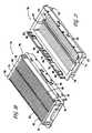
- FIG. 1is a top isometric view of a plug assembly according to a preferred embodiment of this invention
- FIG. 2is a bottom isometric view of a plug assembly according to a preferred embodiment of this invention.
- FIG. 3is an assembly drawing of the plug assembly of FIG. 1 with the plug cover removed;
- FIG. 4is a top perspective view of a preferred embodiment of a common base for the plug assembly of FIGS. 1 and 2 and the receptacle assembly of FIGS. 17 and 18 ;
- FIG. 5is a bottom perspective view of a preferred embodiment of a common base for the plug assembly of FIGS. 1 and 2 and the receptacle assembly of FIGS. 17 and 18 ;
- FIG. 6is a perspective view of a portion of the top of the common base of FIG. 4 ;
- FIG. 7is a perspective view of a portion of the bottom of the common base of FIG. 5 ;
- FIG. 8is a cross-section taken along line 8 — 8 of FIG. 1 ;
- FIG. 9is a cross-section taken along line 9 — 9 of FIG. 1 ;
- FIG. 10is a perspective top view of a plug cover of the plug assembly of FIG. 1 according to the preferred embodiment of the invention.
- FIG. 11is a perspective bottom view of a plug cover of the plug assembly of FIG. 1 according to the preferred embodiment of the invention.
- FIG. 12is a cross-section taken along line 12 — 12 of FIG. 10 ;
- FIG. 13is a cross-section taken along line 13 — 13 of FIG. 10 ;
- FIG. 14is a perspective top view of a spacer according to a preferred embodiment of this invention.
- FIG. 15is a perspective bottom view of a spacer according to a preferred embodiment of this invention.
- FIG. 16is a perspective view of a plug contact assembly before being singulated
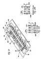
- FIG. 17is a top perspective view of a receptacle assembly according to a preferred embodiment of this invention.
- FIG. 18is a bottom perspective view of a receptacle assembly according to a preferred embodiment of this invention.
- FIG. 19is an assembly drawing of the receptacle assembly of FIGS. 17 and 18 with the receptacle cover removed;
- FIG. 20is a perspective top view of a receptacle cover of the receptacle assembly of FIGS. 17 and 18 according to a preferred embodiment of this invention.
- FIG. 21is a perspective bottom view of a receptacle cover of the receptacle assembly of FIGS. 17 and 18 according to a preferred embodiment of this invention.
- FIG. 22is a cross-section taken along line 22 - 22 of FIG. 17 ;
- FIG. 23is a cross-section taken along line 23 - 23 of FIG. 17 ;
- FIG. 24is a perspective view of a receptacle contact assembly before being singulated
- FIG. 24Ais a schematic diagram of a preferred ground and signal contact configuration
- FIG. 24Bis a schematic diagram of a second preferred signal and ground contact configuration
- FIG. 25is a perspective view of a portion of a second preferred embodiment of a plug assembly
- FIG. 26is a perspective view of a portion of a second preferred embodiment of a receptacle assembly
- FIG. 27is a perspective top view of a second preferred embodiment of a common base for the plug and receptacle assemblies of FIGS. 25 and 26 ;
- FIG. 28is a perspective bottom view of a second preferred embodiment of a common base for the plug and receptacle assemblies of FIGS. 25 and 26 ;
- FIG. 29is a perspective view of a second preferred embodiment of a receptacle contact assembly
- FIG. 30is a side view of a portion of the receptacle contact assembly of FIG. 29 ;
- FIG. 31is a perspective view of a preferred embodiment of an adapter.
- FIG. 32is a schematic diagram of a preferred ground plane and signal contact configuration for the second preferred embodiment.
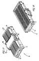
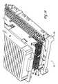
- the electrical connectormay be a board to board mezzanine ball grid array (BGA) connector which includes a mated assembly having a plug assembly 12 , a preferred embodiment of which is shown in FIGS. 1 and 2 , and a receptacle assembly 13 , a preferred embodiment of which is shown in FIGS. 17 and 18 .
- the plug assembly 12mates with the receptacle assembly 13 to form a connector.
- the plug assembly 12 and the receptacle assembly 13have a common base 14 .
- the manufacturing of the plug assembly 12 and the receptacle assembly 13is simplified because the plug assembly 12 and the receptacle assembly 13 can be made from a common base 14 . This is also beneficial because it reduces manufacturing costs.
- FIGS. 1 and 2Top and bottom perspective views of the plug assembly 12 according to a preferred embodiment of this invention are respectively shown in FIGS. 1 and 2 .
- the plug assembly 12preferably includes the common base 14 , a plurality of contact assemblies 16 and a plug cover 18 .
- the plug assembly 12may depending upon the contact height include a spacer 20 , which is depicted in FIGS. 14 and 15 .
- the plug cover 18is preferably mechanically coupled to the spacer 20 by any suitable means, including but not limited to the use of mechanical connections and adhesives.
- the spacer 20is mounted to the base 14 . This construction is also understood with reference to FIG. 3 which depicts a portion of the plug assembly 12 with the plug cover 18 detached from the spacer 20 . ( FIG.
- FIG. 3depicts only a portion of the plug contact assemblies 16 installed, but it will be appreciated that the plug assembly 12 is filled with a plurality of such plug contact assemblies).
- the plug cover 18can be mounted directly to the base 14 , and a spacer 20 need not be used.
- the plug assembly 12is depicted in FIG. 1 and the receptacle assembly 13 is depicted in FIG. 17 as each having a cap 12 a and 13 a , it will be appreciated that these caps 12 a , 13 a (which can be the same cap) are used for manufacturing purposes and do not form part of the connector described herein.
- These caps 12 a , 13 aare for lifting the assemblies during handling and manufacturing.
- the assemblies 12 , 13can be vacuum lifted by applying a suction to the caps 12 a , 13 a ).
- FIGS. 4 and 5A preferred embodiment of the common base 14 for the plug assembly 12 and the receptacle assembly 13 is depicted in FIGS. 4 and 5 .
- This base 14is a common component that can be used to form both the plug and the receptacle.
- FIG. 4is top perspective view of the top 14 a of the base 14
- FIG. 5is a bottom perspective view of the bottom 14 b of the base 14 .
- the base 14may be constructed from any suitable material and is preferably a polymeric material.
- the basecan be constructed in a single piece as shown in the preferred embodiment, which is a single piece of molded plastic, or any number of pieces.
- the top 14 a of the base 14includes a plurality of recesses 22 .
- a closer view of a preferred embodiment of the recesses 22is shown in the perspective view of FIG. 6 .
- Each of the recesses 22are preferably defined by two pairs of opposing angled walls 24 , 26 .
- the angled walls 24 , 26approach each other but do not touch so that they in part define a recess 22 .
- one end of a plug contact of a plug contact assembly 16fits within each recess 22 if the base is to be used as part of a plug assembly.
- a receptacle of a receptacle contact assemblycan be inserted into the recess 22 .
- the construction of the contact plug assemblies 16is further described below.
- FIG. 5depicts the bottom view of the perspective view of the base 14
- FIG. 7depicts an enlarged view of a portion of the bottom 14 b of the base 14
- the recesses 22are defined so that they are preferably substantially rectangular shaped.
- the bottom 14 b of the base 14has a plurality of pockets 25 which are defined by walls 27 .
- the walls 27are preferably configured to define the pockets in a diamond shape, as shown in FIG. 7 .
- a ball grid array connectorwhich is preferably a fusible element and even more preferably solder, can be disposed within each pocket 25 so that each fusible element is in electrical contact with a contact that extends through the recess 22 .
- the fusible elementis a solder ball.
- the term ballis not meant to be limiting as to a particular geometric configuration of the solder.
- the solder balls 29are disposed in the pockets 25 and the plug contacts extend through the base recesses 22 into the pockets 25 . Each plug is wetted to a solder ball 29 in the respective pocket 25 .
- the base 14can be mated to an electrical component in order to form an electrical connection between the solder balls 29 and a circuit.
- the base 14can be mated to a board having an integrated circuit to form electrical connections between the solder balls and the circuit.
- the pockets 25are generally disposed in a pattern of alternating rows such that the centerline of each pocket 25 is aligned with a centerline of another pocket 25 that is two rows away from that pocket 25 .
- the pockets 25are preferably disposed in an interstitial diamond shaped pattern. This diamond shaped interstitial pattern permits the contacts to be more closely packed while maintaining standard commercial pocket dimensions and using standard BGA solder balls. This diamond orientation also provides for additional clearance for the contacts.
- the recess 22 and the pocket 25were both rectangular shaped and the contact if not centered could push against the walls which define the recess or pocket.
- the plug and the receptacle assemblies 12 , 13will undergo power and thermal cycles, which induce thermal stresses upon the contact and the solder. Having solder around the entire perimeter of the end of the contact is beneficial because areas of a contact end which do not have solder wetting (solder attached to the contact) are more susceptible to these stresses. Therefore, having solder around the entire perimeter of the contact can enhance ball retention and T-cycle life.
- the base 14may also have a plurality of tabs 28 extending from opposing sides. These tabs 28 as explained further below fit with channels 38 disposed within the plug cover 18 (shown in FIGS. 10 , 11 ), channels 43 in the spacer 20 (shown in FIGS. 14 and 15 ) or channels 80 in the receptacle cover 70 (which is described below and shown in FIGS. 20 and 21 ) in order to attach the base 14 to either the plug cover 18 , the spacer 20 or the receptacle cover 70 .
- tabs 28 and channels 38 , 43 , 80are used as a connection means in the preferred embodiment, any suitable attachment means can be used. For instance, other connection means can be used including but not limited to fasteners and adhesives.
- Slots 30may also be disposed within the base 14 . Slots 30 are constructed to receive a contact assembly either a plug contact assembly 16 or a receptacle contact assembly 72 (which is discussed in more detail below and shown in FIGS. 19 and 24 ) so that a contact assembly 16 , 72 can be mounted within the base 14 . Attachment of the contact assemblies, both base and receptacle assemblies, are described in further detail below.
- FIGS. 10 and 11An embodiment of the plug cover 18 is depicted in FIGS. 10 and 11 .
- FIG. 10depicts an isometric top view of the plug cover 18
- FIG. 11depicts an isometric bottom view.
- the plug cover 18is preferably a single molded piece, but alternatively may be constructed from a variety of pieces.
- the plug cover 18can be constructed from any suitable material, but preferably a polymeric type material is used.
- the plug cover 18may have a plurality of slots 32 which can each receive a plug contact as best understood with reference to FIGS. 1 and 3 .
- FIG. 1depicts the plug contacts extended up through the slots 32
- FIG. 3depicts slots 32 being inserted over the plug contacts 59 , 61 .
- the slots 32are arranged in rows and there are ten tines 35 per row. There can be, however, any number of slots 32 and the tines 35 can be arranged in numerous other configurations.
- FIG. 12is a cross-section taken along line 12 — 12 of FIG. 10 through a few of the slots 32 .
- the slots 32are in the preferred embodiment defined by a pair of opposed sides 31 which are preferably angled away from each other in order to facilitate the insertion of a contact through them. Walls 33 also define a substantially vertically section of the slots 32 .
- the slots 32may further be defined by tines 35 which extend, as shown in FIGS. 10 and 12 , above the outer surface 36 . These tines 35 provide additional support for the plug contacts and further narrow the slots 32 , as is also shown in FIG. 9 .
- a support member 33 awhich is in the preferred embodiment integrally formed with the plug cover 18 as shown in FIGS. 11 and 13 , extends longitudinally across the middle of the plug cover 18 to provide alignment for the plug contact assembly.
- Extending from opposing sides of the plug cover 18may be members 37 that define channels 38 .
- the tabs 28 of the base 14fit into the channels 38 in order to snap fit the base 14 to the plug cover 18 .
- tabs 44 on the spacer 20as explained below fit into the channels 38 in order to attach the plug cover 18 to a spacer 20 .
- This constructionis shown in the preferred embodiment of FIG. 1 .
- there are eight channels 38 on each member 37 that mate with the eight tabs 28 of either the base 14 or the spacer 20but any suitable number may be used.
- Alternative meansmay be used to attach the plug cover 18 to either the base 14 or the spacer 20 .
- the plug cover 18has walls 39 which are preferably sized and shaped to define an interior 40 for receiving a receptacle assembly.
- the receptacle assembly 13fits snugly within the interior 40 so that a sliding fit is created.
- the corners 42 of the walls 39are preferably sized and shaped so that the corners of the receptacle assembly discussed below will snugly fit within the walls 39 .
- the plug 12 and the receptacle 13can fit together with numerous other constructions, and this is one example of a preferred way to attach the two assemblies 12 , 13 .
- One or more corners of the plug assemblycan be sized or shaped so that those corners mate with only a specific corner of a correspondingly sized or shaped corner of the receptacle cover. This ensures that the covers are mated in the proper orientation.
- FIGS. 14 and 15depict perspective views of a preferred embodiment of a spacer 20 .
- FIGS. 14 and 15are respectively top and bottom perspective views.
- the spacer 20is a single molded piece.
- the spacer 20can be constructed from a plurality of pieces.
- the spacer 20may be a polymeric material, but any suitable material may be used.
- Spacers 20 of different heightscan be used with either the plug assembly 12 or the receptacle assembly 13 in order to achieve a connector of the desired stack height. For greater stack heights, taller or more spacers are used and for lesser stack heights smaller or less spacers are employed.
- a single spacer 20is used in the plug assembly 12 and is connected to the base 14 and the plug cover 18 as shown in FIG. 1 .
- the spacer 20preferably has any suitable means for connecting the spacer 20 to a base 14 or a plug cover 18 .
- the connecting meansis a mechanical type connection means and includes the channels 43 , which can be mated with tabs 28 of the base 14 .
- the spacermay also have tabs 44 to snap fit the spacer to the channels 38 of the plug cover 18 .
- the spacer 20has channels 43 and tabs 44 on two opposing sides of the spacer 20 . Although only one side is shown in FIG. 15 , it will be appreciated that the other side is similarly constructed.
- the spacer 20Disposed within the spacer 20 may be a series of grooves 45 for receiving a contact assembly.
- the grooves 45are preferably defined by a plurality of inwardly extending partitions 47 which support the lateral ends of a contact assembly.
- the spacer 20may also have a plurality of legs 49 extending downward. These legs 49 rest on the upper surface 51 of the base 14 when the spacer is disposed on the base 14 , as shown in FIGS. 1 and 3 , and as also understood by comparing FIGS. 14 and 4 .
- the spacer 20has surfaces 53 which create windows 55 when mated with the base 14 , as best understood in FIG. 3 . These windows 55 serve to reduce the weight of the spacer 20 and provides a flow path for air into the plug assembly for cooling.
- the windows 55are also preferably asymmetric with respect to the centerline. This assists in manufacturing the plug assembly and in orienting the spacer 20 in a vibratory feed system.
- FIG. 16depicts preferred embodiment of a plug contact assembly 16 for use with the plug assembly of FIG. 1 before the contact assembly 16 is singulated to remove portions 57 .
- the plug contact assembly 16includes a plurality of alternating ground 59 and signal contacts 61 . Any number of such contacts can be used to create a plug contact assembly. In a preferred embodiment, ten ground 59 and eight signal contacts 61 are employed.
- the contacts 59 , 61need not be but may be gold striped at their ends 63 which are connected to the solder balls as shown in FIGS. 8 and 9 , to improve wetting of the contacts 59 , 61 .
- the mating ends of the contacts 59 , 61can also be gold striped to provide high reliability and relatively low mating forces.
- the remaining portion of the contacts 59 , 61can be nickel plated to prevent the solder from traveling up the contacts 59 , 61 .
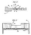
- FIG. 8is a cross-section depicting a plug contact assembly 16 inserted into the plug assembly 12 and shows the ends 63 of the signal contacts connected to a solder ball 29 in a ball pocket 25 of the base 14 .
- the ends of the ground contacts 59 of the contact assembly shownare in a different plane but are likewise wetted to a solder ball in a ball pocket of the base 14 .
- the ends 63 of the contactsextend through the recesses 22 in the base 14 and to the diamond pockets 25 where solder 29 is used to create a solder ball for electrical connection to another electrical component.
- FIG. 9depicts a longitudinal cross section through the plug assembly 12 .
- each contact 59is wetted to the solder 29 in a pocket 25 of the base 14 .
- the contacts 59 , 61can be stamped and then molded to a plastic carrier 65 an embodiment of which is shown in FIG. 16 .
- the ends 67 of the carrier 65are preferably sized and shaped so that they can fit relatively snugly within the slots 30 of the base 14 and the grooves 45 of the spacer 20 .
- FIG. 3which shows a plurality of contact assemblies 16 inserted into the grooves 45 of the spacer 20
- FIG. 8which is a cross-section depicting the plug contact assembly 16 inserted into the slots 30 of the base 14 and the groove 45 of the spacer 20 .
- the assembly of the plug assembly 12can best be understood by starting with a base 14 , as shown in FIGS. 4 and 5 .
- a spacer 20if used, can be snap fit to the base 14 by snapping the tabs 28 of the base 14 into the channels 43 of the spacer 20 as shown in FIG. 15 .
- the contact assemblies 16can then be inserted into each of the slots 30 in the base 14 and grooves 45 of the spacer 20 .
- a plug cover 18can be snap fit to the spacer 20 with tabs 44 and channels 38 .
- Soldercan then be inserted in each pocket around the contact end 63 of the contacts 59 , 61 to create the solder ball connections.
- the diamond shape construction of the pockets 25ensures wetting around the perimeter of the contacts as described above.
- the spacer 20may not be required. In that event, the plug cover 18 can be attached directly to the base 14 with the base tabs 28 and the plug cover channels 38 .
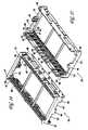
- FIGS. 17 and 18A preferred embodiment of the receptacle assembly 13 to which the plug assembly 12 can be mated is shown in FIGS. 17 and 18 .
- FIG. 17is a perspective view of the top of the receptacle assembly 12
- FIG. 18is a perspective view of the bottom or underside of the receptacle assembly 12 .
- the receptacle assembly 13generally includes a base 14 , a receptacle cover 70 and a receptacle contact assembly 72 , a plurality of which are depicted in FIG. 19 .
- a spacer 20if needed based on contact height could be used between the base 14 and the cover 70 .
- FIG. 19shows the construction of the receptacle assembly 13 with a plurality of receptacle contact assemblies 72 inserted into the base 14 , and the receptacle cover 70 being coupled to the base 14 .
- the base 14 of the receptacle assembly 13is preferably the same base that is used in the plug assembly 12 and which is depicted in FIGS. 4-7 .
- the construction of the receptacle base 14can be understood by referring to the discussion above.
- manufacturingis simpler and less costly in comparison to having to produce two different bases for the plug and the receptacle assemblies.
- FIGS. 20 and 21depict a preferred embodiment of the receptacle cover 70 which interfaces with the plug cover 18 .
- FIG. 20is a top isometric view of the receptacle cover 70
- FIG. 21is a bottom isometric view.
- the receptacle cover 70is preferably a single molded piece, but the receptacle cover 70 may be constructed from a multitude of pieces. Any suitable material but preferably a polymer can be used to manufacture the receptacle cover 70 .
- the receptacle cover 70preferably has a first portion 74 that is shaped so as to correspond to the interior 40 of the plug cover 18 so that the receptacle cover 70 slide fits into the interior 40 of the plug cover 18 as best understood with reference to FIGS.
- the plug cover 18 of the plug assembly 12can fit over the receptacle cover 70 to connect the two assemblies and form a connector.
- the corners 76 of the receptacle cover 70may be keyed or sized and shaped so as to slidingly engage the corners 42 of the plug assembly 12 , so that the two assemblies slide together in an relatively snug sliding fit.
- the receptacle cap 70has laterally extending portions 78 that each comprise a plurality of channels 80 for receiving tabs 28 of base 14 . In a preferred embodiment, there are eight channels 80 in each laterally extending portion 78 .
- the receptacle cover 70snap fits to the tabs 28 of the base 14 to form the receptacle assembly 13 shown in FIGS. 17 and 18 .
- the top of the receptacle cap 70preferably has a plurality of laterally extending slots 82 . These slots 82 are for receiving the plug contacts 59 , 61 . As will be appreciated by viewing FIGS. 1 and 17 , the plug contacts can extend down through the slots 82 and mate with a corresponding receptacle contact 84 shown in FIG. 19 .
- FIG. 22also depicts the receptacle contacts 84 which are disposed beneath a slot 82 .
- the slots 82are preferably defined in part by opposing walls 88 which are angled toward each to direct the plug contacts 59 , 61 to a corresponding receptacle contact 84 , 86 .
- the support member 90Extending longitudinally along the underside of the receptacle cover 70 is preferably a support member 90 .
- the support member 90preferably has a plurality of ridges 92 and grooves 94 for receiving a receptacle contact assembly member 96 , as shown in the cross-section of FIG. 23 .
- FIG. 24depicts a perspective view of a preferred embodiment of a receptacle contact assembly 72 that can be used with this invention before it has been singulated to remove portions 98 .
- the receptacle contact assembly 72includes alternating ground 84 and signal 86 contacts and a plastic carrier 100 . Although the contacts differ in construction, the general construction of the receptacle contact assembly 72 can be understood with reference to the discussion regarding the plug contact assembly 16 .
- the receptacle contactsare preferably stamped and then molded to a plastic carrier 100 . They are then singulated to remove unwanted portions 98 .
- the ends 102 of the receptacle contactscan be but need not be gold striped to ensure wetting with solder 29 when disposed in a base pocket 25 as shown in FIGS.
- the mating ends of the contactscan also be gold striped for high reliability and to reduce mating forces.
- the ends 104 of the plastic carrier 100are preferably sized and shaped so that they can be inserted into the slots 30 of the base 14 , as shown in FIG. 19 .
- the receptacle contact assembly 72can also have support member 96 which as shown in the cross-section of FIG. 23 fits relatively snugly within a groove 94 defined by two of the ridges 92 in the support member 90 of the receptacle cover 70 . This provides stability for the receptacle contact assembly 13 .
- one end of the receptacle contact 106has groups of opposing forks 108 that define a space 110 for receiving a plug type contact 59 , 61 .
- a plug contact 59 , 61can fit between the forked end 108 of a receptacle contact 84 , 86 in order to provide an electrical connection.
- the receptacle assembly 13can be constructed by inserting a plurality of receptacle contact assemblies 72 into the slots 30 of the base 14 , as best understood with reference to FIG. 19 .
- the ends 104 of the plastic carrier 100are sized and shaped so as to fit relatively snugly within the slots 30 .
- the receptacle cover 70snap fits over the base 14 by snapping the tabs 28 of the base 14 into the channels 80 of the receptacle cover 70 , as shown in FIG. 19 .
- the support members 96 of the receptacle contact assemblies 72fit within the grooves 94 of the receptacle cover support member 90 .
- the plug and receptacle assemblies 12 , 13are mated by inserting the receptacle cover 70 into the interior 40 of the plug cover 18 .
- the receptacle corners 76 of the receptacle cover 70fit relatively snugly into the corners 42 of the plug cover 18 to form a sliding and keyed fit.
- the plug contacts 59 , 61 shown in FIG. 3extend through the slots 82 of the receptacle cover 70 and mate with a corresponding receptacle contact 84 , 86 to create an electrical connection between each contact.
- the connectorcan be mated to other electrical components such as printed circuit boards which have circuits that can be placed in electrical contact with the plug 59 , 61 and receptacle contacts 84 , 86 and the solder balls 29 which surround them.
- FIG. 24Ais a schematic diagram of the arrangement of the signal and ground contacts in the first preferred embodiment.
- the signal and ground contactsare oriented in what is referred to as an “in-line stripline” configuration.
- individual ground contacts 59 , 84are disposed on either side of the signal contacts 61 , 86 to provide an electrical ground reference for the signal contacts and to provide the electrical stripline configuration.
- the geometric relationship between the signal and ground contacts, including the gap H, the thickness t, the width w and pitch p,can be varied to achieve the desired connector impedance and electrical performance.
- the in-line stripline configurationhas several advantages (relative to the I-Beam approach described below) including advantages in terms of costs and manufacturing.
- the same contactcan be used in all locations, and the contacts can be continuously stamped, which produces relatively consistent contact gaps (H). This is beneficial in achieving the desired optimum electrical performance.
- all connector contactscan be used for either differential or single ended signals or any combination of these. Molding of the carrier 104 shown in FIG. 24 is also easier because the contacts can be molded in a vertical row with contacts oriented so that the thin width is in the direction of mold closing.
- Another advantageis that because ground planes are not used, the connector mass (including its thermal mass) is lower which results in easier application to customers' printed circuit boards (PCB).
- FIG. 24Bdepicts a mezzanine in line stripline configuration in which the signal contacts are surrounded by ground contacts. This configuration is advantageous in reducing cross-talk.
- plug assembly and the receptacle assembly set forth abovecan be made without departing from the spirit of the inventions set forth herein. Examples of such variations include but are not limited to ways to connect the plug and receptacle assemblies and their components, the arrangement of contacts within the assemblies, the configuration of the contact assemblies, the support for the contacts, and the shape and size of the assemblies.
- FIG. 25depicts an embodiment of plug cover 518 attached to a spacer 520 which can be used to form a plug assembly 512 .
- a plurality of plug contact assembliesare installed within the plug cover 518 and the spacer 520 .
- FIG. 26illustrates a receptacle cover 570 detached from a spacer 520 and a plurality of receptacle contact assemblies 572 installed within the spacer 520 .
- the receptacle cover 570 and the plug cover 518can be snap fit to the spacer 520 .
- FIGS. 25 and 26depict spacers 520 being used in the plug and receptacle assemblies, it will be understood that either assembly could be made with or without a spacer 520 . Spacers 520 are used if the contact height dictates their use.
- FIGS. 27 and 28respectively illustrate a top and bottom perspective view of an embodiment of a common base 514 that can be used with both the plug assembly shown in FIG. 25 and the receptacle assembly shown in FIG. 26 .
- the common base 514can attach to the spacer 520 used in either assembly.
- the tabs 528 of the base 514are snap fit to channels (not shown) in the spacers 520 .
- the common base 514has slots 530 for receiving either a plug or a receptacle contact assembly 516 , 572 .
- recesses 522are disposed in the top 514 a of the base 514 similar to those described in the first embodiment.
- a pair of opposing angled walls 524 , 526create each recess 522 and narrow the recess 522 to facilitate the insertion of a contact end through the recess 522 .
- Diamond shaped pockets 525are disposed on the bottom 514 b of the base 514 beneath each recess 522 .
- the diamond shaped pockets 525are configured as in the first embodiment, so that the end of the contact extending through the recess 522 will have clearance to receive solder 529 around its periphery.
- FIGS. 29 and 30depict an embodiment of a receptacle contact assembly 572 .
- the receptacle contact assembly 572has a plurality of receptacle contacts 584 , a pair of ground plates 606 and a pair of plastic carriers 608 .
- the receptacle contactscan be formed by stamping and then being molded to the plastic carriers 608 .
- the plastic carriers 608may have protrusions 610 extending laterally for insertion into a corresponding hole 612 in a ground plate 606 , as shown in FIG. 29 .
- FIGS. 29 and 30depict a receptacle contact assembly 572
- plug type contactscould be substituted for the receptacle contacts and the plug contact assembly 516 would otherwise be the same as that depicted in FIGS. 29 and 30 .
- the contact assemblies 516 , 572are mounted within the plug 512 and the receptacle 513 by fitting either end of the ground plates 606 of the contact assembly 516 , 572 in the slots 530 of the base 514 and the grooves (not shown) of the spacer 520 . This is best understood with reference to FIG. 26 .
- the plug and the receptacle of this second embodimentcan be mated together by inserting the receptacle cover 570 into the interior of the plug cover 518 .
- the receptacle and plug covers 518 , 570are sized and shaped so as to from a relatively snug slide fit. When mated, the plug contacts extend through the slots in the receptacle covers to create electrical connections between the contacts.
- FIG. 32is a schematic description of the configuration of the contacts in the second embodiment.
- This arrangementis referred to as a stripline I-Beam configuration.
- ground plates 606provide the electrical ground reference for the signal contacts. This is in contrast to the in line stripline approach described above which uses individual ground contacts.
- the geometric relationship including the pitch p, the thickness t, and the gap h, and the width wcan be controlled to obtain the desired connector impedance and electrical performance.
- the in-line stripline configurationhas some advantages, which are noted above, it will be understood, that either the in-line stripline or I-Beam stripline configuration can be used to obtain the desired electrical performance.
- FIG. 31depicts an embodiment of an adaptor 610 that can be used to form a plug to adaptor to plug assembly.
- the adaptor 610can be manufactured from plastic or any suitable material.
- the adapter 610is constructed so as to mate with two plugs 512 when longer connections are needed than just the plug 512 to the receptacle 513 .
- the adapter 610can be attached at one of its ends 612 to the plug 512 and at the other end 614 to another plug 512 .
- the adapter 610can be constructed from a receptacle cover 570 at either end for mating with a plug assembly 512 .
- the adaptor 610can also have none or one or more spacers 520 depending upon the length of the connection needed.
- a plurality of contactscan be installed within the adapter that have ends for mating with plug contacts.
- the embodiment adapter 610 shownis for use with the second embodiment, it will be appreciated that the adapter 610 can have other embodiments including one for mating with the first embodiment shown.
- a plug to plug adaptor 610has been described, it will be appreciated that a receptacle to receptacle adaptor could be formed, as well as various other combinations of plug and receptacle adaptors.
- a modular connector assemblycan be formed that accommodates a selected stack height. After selecting a stack height, the proper contact height and contact assembly for both the plug 12 and the receptacle 13 can be selected. The plug and the receptacle contact assemblies 16 , 72 of the selected stack height can be inserted into and coupled to the base 14 of the respective plug 12 and the receptacle 13 . If needed for the stack height, one or more spacers 20 can be connected to either or both the receptacle base 14 and the plug base 14 . For the plug, the plug cover 18 can then be coupled to the base 14 .
- one or more spacers 20can be attached to the plug base 14 , and the plug cover 18 can be mounted to the top spacer 20 .
- a receptacle cover 70can be coupled to the base 14 .
- one or more spacers 20can be attached to the receptacle base 14 , and the receptacle cover 70 can then be attached to the top most spacer 20 . Then the plug 12 and the receptacle 13 can be mated by attaching the plug cover 18 to the receptacle cover 70 .
- an adaptor 110can be attached to the receptacle 13 and the plug 12 or to two plugs or two receptacles instead of attaching the receptacle directly to the plug 12 .
- the plug base 14can then be attached to a board or other electrical component, and the receptacle base 13 can likewise be attached to a board or another electrical component.
- a modular connectorcan be constructed to accommodate a selected stack height.
- the modular connectorneed only include those components needed for the given stack height. This is advantageous because a modular connector can be built with the given components to any desired stack height. A new type of connector need not be designed for each stack height. This simplifies the manufacturing process because a variety of components can be manufactured to make a variety of connectors instead of dedicated components for connectors of different heights.
- a common base 14is used for both the plug and the receptacle assemblies 12 , 13 .
- an adapter 110can be used with common components including a receptacle cover and a plug cover, and each assembly can use a common spacer.
- connectorshaving a stack height between the range of about 10-35 mm. and contact quality of about 100 to 400 signal contacts per connector.
- One advantage of the connectors of this inventionis the interstitial diamond pattern of pockets 25 in the base 14 . This provides for closely packing the contacts to maintain the size of the connector relatively small while maintaining a good signal and low cross talk.
- the diamond shape pockets 25also ensure good contact wetting or solder attached around the entire periphery of the contact ends. This as described above ensures good electrical performance.
Landscapes
- Coupling Device And Connection With Printed Circuit (AREA)
- Connector Housings Or Holding Contact Members (AREA)
- Manufacturing Of Electrical Connectors (AREA)
- Details Of Connecting Devices For Male And Female Coupling (AREA)
Abstract
Description
Claims (18)
Priority Applications (1)
| Application Number | Priority Date | Filing Date | Title |
|---|---|---|---|
| US10/940,329US7407387B2 (en) | 2001-07-31 | 2004-09-14 | Modular mezzanine connector |
Applications Claiming Priority (2)
| Application Number | Priority Date | Filing Date | Title |
|---|---|---|---|
| US09/919,321US6869292B2 (en) | 2001-07-31 | 2001-07-31 | Modular mezzanine connector |
| US10/940,329US7407387B2 (en) | 2001-07-31 | 2004-09-14 | Modular mezzanine connector |
Related Parent Applications (1)
| Application Number | Title | Priority Date | Filing Date |
|---|---|---|---|
| US09/919,321ContinuationUS6869292B2 (en) | 2001-07-31 | 2001-07-31 | Modular mezzanine connector |
Publications (2)
| Publication Number | Publication Date |
|---|---|
| US20050032437A1 US20050032437A1 (en) | 2005-02-10 |
| US7407387B2true US7407387B2 (en) | 2008-08-05 |
Family
ID=25441886
Family Applications (3)
| Application Number | Title | Priority Date | Filing Date |
|---|---|---|---|
| US09/919,321Expired - LifetimeUS6869292B2 (en) | 2001-07-31 | 2001-07-31 | Modular mezzanine connector |
| US10/779,172Expired - LifetimeUS7429176B2 (en) | 2001-07-31 | 2004-02-11 | Modular mezzanine connector |
| US10/940,329Expired - LifetimeUS7407387B2 (en) | 2001-07-31 | 2004-09-14 | Modular mezzanine connector |
Family Applications Before (2)
| Application Number | Title | Priority Date | Filing Date |
|---|---|---|---|
| US09/919,321Expired - LifetimeUS6869292B2 (en) | 2001-07-31 | 2001-07-31 | Modular mezzanine connector |
| US10/779,172Expired - LifetimeUS7429176B2 (en) | 2001-07-31 | 2004-02-11 | Modular mezzanine connector |
Country Status (12)
| Country | Link |
|---|---|
| US (3) | US6869292B2 (en) |
| EP (2) | EP1494320B1 (en) |
| JP (1) | JP4142367B2 (en) |
| CN (2) | CN1244184C (en) |
| AT (1) | ATE305176T1 (en) |
| CA (1) | CA2394432A1 (en) |
| DE (1) | DE60206228T2 (en) |
| ES (1) | ES2246364T3 (en) |
| HU (2) | HU227144B1 (en) |
| MY (1) | MY142558A (en) |
| SG (1) | SG118146A1 (en) |
| TW (1) | TW571470B (en) |
Cited By (23)
| Publication number | Priority date | Publication date | Assignee | Title |
|---|---|---|---|---|
| US20090130912A1 (en)* | 2007-11-15 | 2009-05-21 | Fci Americas Technology, Inc. | Electrical connector mating guide |
| US20100055988A1 (en)* | 2007-08-30 | 2010-03-04 | Shuey Joseph B | Mezzanine-type electrical connectors |
| US20100075516A1 (en)* | 2008-09-25 | 2010-03-25 | Horchler David C | Hermaphroditic Electrical Connector |
| US7762843B2 (en) | 2006-12-19 | 2010-07-27 | Fci Americas Technology, Inc. | Shieldless, high-speed, low-cross-talk electrical connector |
| US8267721B2 (en) | 2009-10-28 | 2012-09-18 | Fci Americas Technology Llc | Electrical connector having ground plates and ground coupling bar |
| US8425236B2 (en) | 2011-05-16 | 2013-04-23 | International Business Machines Corporation | Tall mezzanine connector |
| US8485831B2 (en) | 2011-01-06 | 2013-07-16 | International Business Machines Corporation | Tall mezzanine connector |
| US8616919B2 (en) | 2009-11-13 | 2013-12-31 | Fci Americas Technology Llc | Attachment system for electrical connector |
| US8764464B2 (en) | 2008-02-29 | 2014-07-01 | Fci Americas Technology Llc | Cross talk reduction for high speed electrical connectors |
| USD718253S1 (en) | 2012-04-13 | 2014-11-25 | Fci Americas Technology Llc | Electrical cable connector |
| US8905651B2 (en) | 2012-01-31 | 2014-12-09 | Fci | Dismountable optical coupling device |
| USD720698S1 (en) | 2013-03-15 | 2015-01-06 | Fci Americas Technology Llc | Electrical cable connector |
| US8944831B2 (en) | 2012-04-13 | 2015-02-03 | Fci Americas Technology Llc | Electrical connector having ribbed ground plate with engagement members |
| USD727268S1 (en) | 2012-04-13 | 2015-04-21 | Fci Americas Technology Llc | Vertical electrical connector |
| USD727852S1 (en) | 2012-04-13 | 2015-04-28 | Fci Americas Technology Llc | Ground shield for a right angle electrical connector |
| US9048583B2 (en) | 2009-03-19 | 2015-06-02 | Fci Americas Technology Llc | Electrical connector having ribbed ground plate |
| USD733662S1 (en) | 2013-01-25 | 2015-07-07 | Fci Americas Technology Llc | Connector housing for electrical connector |
| USD746236S1 (en) | 2012-07-11 | 2015-12-29 | Fci Americas Technology Llc | Electrical connector housing |
| US9257778B2 (en) | 2012-04-13 | 2016-02-09 | Fci Americas Technology | High speed electrical connector |
| US9277649B2 (en) | 2009-02-26 | 2016-03-01 | Fci Americas Technology Llc | Cross talk reduction for high-speed electrical connectors |
| US9362638B2 (en)* | 2014-09-03 | 2016-06-07 | Amphenol Corporation | Overmolded contact wafer and connector |
| US9543703B2 (en) | 2012-07-11 | 2017-01-10 | Fci Americas Technology Llc | Electrical connector with reduced stack height |
| US10297966B1 (en)* | 2018-01-15 | 2019-05-21 | Te Connectivity Corporation | Mating adapter for an electrical connector assembly |
Families Citing this family (87)
| Publication number | Priority date | Publication date | Assignee | Title |
|---|---|---|---|---|
| US6869292B2 (en)* | 2001-07-31 | 2005-03-22 | Fci Americas Technology, Inc. | Modular mezzanine connector |
| US6981883B2 (en)* | 2001-11-14 | 2006-01-03 | Fci Americas Technology, Inc. | Impedance control in electrical connectors |
| US20050196987A1 (en)* | 2001-11-14 | 2005-09-08 | Shuey Joseph B. | High density, low noise, high speed mezzanine connector |
| US20050170700A1 (en)* | 2001-11-14 | 2005-08-04 | Shuey Joseph B. | High speed electrical connector without ground contacts |
| US6994569B2 (en)* | 2001-11-14 | 2006-02-07 | Fci America Technology, Inc. | Electrical connectors having contacts that may be selectively designated as either signal or ground contacts |
| CN100483886C (en)* | 2001-11-14 | 2009-04-29 | Fci公司 | Crosstalk reduction for electrical connectors |
| US7390200B2 (en)* | 2001-11-14 | 2008-06-24 | Fci Americas Technology, Inc. | High speed differential transmission structures without grounds |
| TW558134U (en)* | 2003-03-07 | 2003-10-11 | Hon Hai Prec Ind Co Ltd | A pick up cap for a CPU socket |
| US7077702B2 (en)* | 2003-08-05 | 2006-07-18 | Tyco Electronics Corporation | Terminal position assurance with forward interlocking face keying |
| US7524209B2 (en)* | 2003-09-26 | 2009-04-28 | Fci Americas Technology, Inc. | Impedance mating interface for electrical connectors |
| US7137832B2 (en)* | 2004-06-10 | 2006-11-21 | Samtec Incorporated | Array connector having improved electrical characteristics and increased signal pins with decreased ground pins |
| US7322855B2 (en)* | 2004-06-10 | 2008-01-29 | Samtec, Inc. | Array connector having improved electrical characteristics and increased signal pins with decreased ground pins |
| US7281950B2 (en)* | 2004-09-29 | 2007-10-16 | Fci Americas Technology, Inc. | High speed connectors that minimize signal skew and crosstalk |
| US7104808B2 (en)* | 2005-01-20 | 2006-09-12 | Hon Hai Precision Ind. Co., Ltd. | Mating extender for electrically connecting with two electrical connectors |
| US20060228912A1 (en)* | 2005-04-07 | 2006-10-12 | Fci Americas Technology, Inc. | Orthogonal backplane connector |
| US7371129B2 (en)* | 2005-04-27 | 2008-05-13 | Samtec, Inc. | Elevated height electrical connector |
| US20060245137A1 (en)* | 2005-04-29 | 2006-11-02 | Fci Americas Technology, Inc. | Backplane connectors |
| US7097465B1 (en)* | 2005-10-14 | 2006-08-29 | Hon Hai Precision Ind. Co., Ltd. | High density connector with enhanced structure |
| US7264488B2 (en)* | 2006-01-03 | 2007-09-04 | Fci Americas Technology, Inc. | Pickup cap for electrical connector |
| US7553182B2 (en)* | 2006-06-09 | 2009-06-30 | Fci Americas Technology, Inc. | Electrical connectors with alignment guides |
| US7462924B2 (en)* | 2006-06-27 | 2008-12-09 | Fci Americas Technology, Inc. | Electrical connector with elongated ground contacts |
| US7320609B1 (en) | 2006-07-31 | 2008-01-22 | Fci Americas Technology, Inc. | Backplane connector |
| US7500871B2 (en)* | 2006-08-21 | 2009-03-10 | Fci Americas Technology, Inc. | Electrical connector system with jogged contact tails |
| US7713088B2 (en)* | 2006-10-05 | 2010-05-11 | Fci | Broadside-coupled signal pair configurations for electrical connectors |
| US7708569B2 (en)* | 2006-10-30 | 2010-05-04 | Fci Americas Technology, Inc. | Broadside-coupled signal pair configurations for electrical connectors |
| US7637784B2 (en)* | 2007-01-29 | 2009-12-29 | Fci Americas Technology, Inc. | Disk drive interposer |
| US7811100B2 (en)* | 2007-07-13 | 2010-10-12 | Fci Americas Technology, Inc. | Electrical connector system having a continuous ground at the mating interface thereof |
| JP4514064B2 (en)* | 2007-09-10 | 2010-07-28 | ヒロセ電機株式会社 | Circuit board electrical connector |
| US7867032B2 (en) | 2008-10-13 | 2011-01-11 | Tyco Electronics Corporation | Connector assembly having signal and coaxial contacts |
| US7896698B2 (en)* | 2008-10-13 | 2011-03-01 | Tyco Electronics Corporation | Connector assembly having multiple contact arrangements |
| US7740489B2 (en)* | 2008-10-13 | 2010-06-22 | Tyco Electronics Corporation | Connector assembly having a compressive coupling member |
| US7637777B1 (en) | 2008-10-13 | 2009-12-29 | Tyco Electronics Corporation | Connector assembly having a noise-reducing contact pattern |
| US7736183B2 (en)* | 2008-10-13 | 2010-06-15 | Tyco Electronics Corporation | Connector assembly with variable stack heights having power and signal contacts |
| JP5405582B2 (en) | 2008-11-14 | 2014-02-05 | モレックス インコーポレイテド | Resonance change connector |
| MY155071A (en) | 2008-12-12 | 2015-08-28 | Molex Inc | Resonance modifying connector |
| US7976326B2 (en)* | 2008-12-31 | 2011-07-12 | Fci Americas Technology Llc | Gender-neutral electrical connector |
| JP5250450B2 (en)* | 2009-02-27 | 2013-07-31 | 第一電子工業株式会社 | Electrical connector |
| US8113851B2 (en) | 2009-04-23 | 2012-02-14 | Tyco Electronics Corporation | Connector assemblies and systems including flexible circuits |
| US8036500B2 (en)* | 2009-05-29 | 2011-10-11 | Avago Technologies Fiber Ip (Singapore) Pte. Ltd | Mid-plane mounted optical communications system and method for providing high-density mid-plane mounting of parallel optical communications modules |
| US8608510B2 (en)* | 2009-07-24 | 2013-12-17 | Fci Americas Technology Llc | Dual impedance electrical connector |
| CN102725919B (en)* | 2009-12-30 | 2015-07-08 | Fci公司 | Electrical connector with impedance tuning ribs |
| US7918683B1 (en) | 2010-03-24 | 2011-04-05 | Tyco Electronics Corporation | Connector assemblies and daughter card assemblies configured to engage each other along a side interface |
| US20110250767A1 (en)* | 2010-04-08 | 2011-10-13 | Alan Crighton | Electrical connector system having transition assembly |
| CN107069274B (en) | 2010-05-07 | 2020-08-18 | 安费诺有限公司 | High performance cable connector |
| US9136634B2 (en) | 2010-09-03 | 2015-09-15 | Fci Americas Technology Llc | Low-cross-talk electrical connector |
| CN103563179B (en)* | 2011-03-17 | 2016-09-07 | 莫列斯有限公司 | Connector and connector system |
| US8845351B2 (en) | 2011-04-08 | 2014-09-30 | Fci Americas Technology Llc | Connector housing with alignment guidance feature |
| SG185162A1 (en)* | 2011-04-28 | 2012-11-29 | 3M Innovative Properties Co | An electrical connector |
| US8657616B2 (en) | 2011-05-24 | 2014-02-25 | Fci Americas Technology Llc | Electrical contact normal force increase |
| US9231325B2 (en) | 2011-05-26 | 2016-01-05 | Fci Americas Technology Llc | Electrical contact with male termination end having an enlarged cross-sectional dimension |
| CN102420375B (en)* | 2011-06-01 | 2013-11-27 | 吴江嘉美电子有限公司 | Board end high-frequency connector shielding device |
| USD718243S1 (en) | 2012-04-16 | 2014-11-25 | Fci Americas Technology Llc | Vertical electrical connector |
| USD718244S1 (en)* | 2012-05-03 | 2014-11-25 | Fci Americas Technology Llc | Vertical electrical connector |
| JP5863041B2 (en)* | 2012-06-01 | 2016-02-16 | アルプス電気株式会社 | Socket for electronic parts |
| US9240644B2 (en) | 2012-08-22 | 2016-01-19 | Amphenol Corporation | High-frequency electrical connector |
| US8979551B2 (en) | 2012-11-29 | 2015-03-17 | Samtec, Inc. | Low-profile mezzanine connector |
| USD718248S1 (en) | 2012-12-11 | 2014-11-25 | Fci Americas Technology Llc | Vertical electrical connector |
| USD718250S1 (en) | 2012-12-11 | 2014-11-25 | Fci Americas Technology Llc | Vertical electrical connector |
| USD718249S1 (en) | 2012-12-11 | 2014-11-25 | Fci Americas Technology Llc | Vertical electrical connector |
| CN104078780B (en) | 2013-03-25 | 2019-07-19 | 安费诺富加宜(亚洲)私人有限公司 | Cable connector assembly and electrical connector system including cable connector assembly |
| CN115411547A (en) | 2014-01-22 | 2022-11-29 | 安费诺有限公司 | Electrical connector, subassembly, module, cable assembly, electrical assembly and circuit board |
| DE102014102171B4 (en)* | 2014-02-20 | 2015-10-29 | Harting Electric Gmbh & Co. Kg | contact support |
| US10396481B2 (en) | 2014-10-23 | 2019-08-27 | Fci Usa Llc | Mezzanine electrical connector |
| CN108701922B (en) | 2015-07-07 | 2020-02-14 | Afci亚洲私人有限公司 | Electrical connector |
| US9911565B2 (en)* | 2015-10-01 | 2018-03-06 | Littelfuse, Inc. | Sealed modular power distribution apparatus |
| CN112151987B (en) | 2016-08-23 | 2022-12-30 | 安费诺有限公司 | Configurable high performance connector |
| US11239639B2 (en) | 2016-09-30 | 2022-02-01 | TE Connectivity Services Gmbh | Assembly and method for sealing a bundle of wires |
| US10103458B2 (en) | 2017-02-07 | 2018-10-16 | Te Connectivity Corporation | System and method for sealing electrical terminals |
| US10109947B2 (en) | 2017-02-07 | 2018-10-23 | Te Connectivity Corporation | System and method for sealing electrical terminals |
| US10483661B2 (en) | 2017-02-07 | 2019-11-19 | Te Connectivity Corporation | System and method for sealing electrical terminals |
| US10404014B2 (en) | 2017-02-17 | 2019-09-03 | Fci Usa Llc | Stacking electrical connector with reduced crosstalk |
| CN110800172B (en)* | 2017-04-28 | 2021-06-04 | 富加宜(美国)有限责任公司 | High frequency BGA connector |
| US9947634B1 (en)* | 2017-06-13 | 2018-04-17 | Northrop Grumman Systems Corporation | Robust mezzanine BGA connector |
| CN108054563B (en)* | 2018-01-09 | 2024-06-07 | 富加宜连接器(东莞)有限公司 | Double-plastic-seat combined connector |
| US10297946B1 (en) | 2018-04-19 | 2019-05-21 | Te Connectivity Corporation | Apparatus and methods for sealing electrical connections |
| US10470313B1 (en) | 2018-07-02 | 2019-11-05 | Te Connectivity Corporation | Solder ball module for contact assembly of an electrical connector |
| US11257612B2 (en) | 2018-07-26 | 2022-02-22 | TE Connectivity Services Gmbh | Assembly and method for sealing a bundle of wires |
| CN208862209U (en) | 2018-09-26 | 2019-05-14 | 安费诺东亚电子科技(深圳)有限公司 | A connector and its applied PCB board |
| CN111585098B (en) | 2019-02-19 | 2025-08-19 | 安费诺有限公司 | High-speed connector |
| TWI887339B (en) | 2020-01-27 | 2025-06-21 | 美商Fci美國有限責任公司 | High speed, high density direct mate orthogonal connector |
| WO2021154702A1 (en) | 2020-01-27 | 2021-08-05 | Fci Usa Llc | High speed connector |
| US11569618B2 (en)* | 2020-06-02 | 2023-01-31 | Yamaichi Electronics Co., Ltd. | Socket for high-speed transmission |
| CN215816516U (en) | 2020-09-22 | 2022-02-11 | 安费诺商用电子产品(成都)有限公司 | Electrical connector |
| CN213636403U (en) | 2020-09-25 | 2021-07-06 | 安费诺商用电子产品(成都)有限公司 | Electrical connector |
| CN215266741U (en) | 2021-08-13 | 2021-12-21 | 安费诺商用电子产品(成都)有限公司 | High-performance card connector meeting high-bandwidth transmission |
| KR102395626B1 (en)* | 2021-11-11 | 2022-05-11 | 주식회사 위드웨이브 | Pin array assembly and connector for high speed signal transmission with using the same |
| KR102395625B1 (en)* | 2021-11-11 | 2022-05-11 | 주식회사 위드웨이브 | Connector for high speed signal transmission with have rigid alignment function |
Citations (24)
| Publication number | Priority date | Publication date | Assignee | Title |
|---|---|---|---|---|
| US4045105A (en) | 1974-09-23 | 1977-08-30 | Advanced Memory Systems, Inc. | Interconnected leadless package receptacle |
| US4148543A (en)* | 1978-04-28 | 1979-04-10 | General Dynamics Corporation | Suppressor for electromagnetic interference |
| US5098311A (en) | 1989-06-12 | 1992-03-24 | Ohio Associated Enterprises, Inc. | Hermaphroditic interconnect system |
| US5334029A (en) | 1993-05-11 | 1994-08-02 | At&T Bell Laboratories | High density connector for stacked circuit boards |
| US5387139A (en) | 1993-04-30 | 1995-02-07 | The Whitaker Corporation | Method of making a pin grid array and terminal for use therein |
| US5527189A (en) | 1992-09-28 | 1996-06-18 | Berg Technology, Inc. | Socket for multi-lead integrated circuit packages |
| GB2299465A (en) | 1995-03-29 | 1996-10-02 | Whitaker Corp | Electrical connector housing assembly with readily removable insert |
| US5562442A (en) | 1994-12-27 | 1996-10-08 | Eisenmann Corporation | Regenerative thermal oxidizer |
| US5573409A (en) | 1991-10-17 | 1996-11-12 | Itt Corporation | Interconnector |
| US5664968A (en) | 1996-03-29 | 1997-09-09 | The Whitaker Corporation | Connector assembly with shielded modules |
| GB2312566A (en) | 1996-04-25 | 1997-10-29 | Motorola Israel Ltd | An adapter |
| US5730606A (en) | 1996-04-02 | 1998-03-24 | Aries Electronics, Inc. | Universal production ball grid array socket |
| US5782656A (en) | 1994-04-14 | 1998-07-21 | Siemens Aktiengesellschaft | Plug-type connector for backplate wirings |
| US5795191A (en) | 1996-09-11 | 1998-08-18 | Preputnick; George | Connector assembly with shielded modules and method of making same |
| US5904594A (en) | 1994-12-22 | 1999-05-18 | Siemens Aktiengesellschaft | Electrical connector with shielding |
| USRE36217E (en) | 1995-02-06 | 1999-06-01 | Minnesota Mining And Manufacturing Company | Top load socket for ball grid array devices |
| US5975921A (en)* | 1997-10-10 | 1999-11-02 | Berg Technology, Inc. | High density connector system |
| US6024584A (en) | 1996-10-10 | 2000-02-15 | Berg Technology, Inc. | High density connector |
| GB2345807A (en) | 1999-01-18 | 2000-07-19 | Tat Kwong Cheung | An electrical connector adaptor |
| US6097609A (en) | 1998-12-30 | 2000-08-01 | Intel Corporation | Direct BGA socket |
| US6146208A (en) | 1997-06-17 | 2000-11-14 | Commscope | Field connector adaptor |
| US6409543B1 (en)* | 2001-01-25 | 2002-06-25 | Teradyne, Inc. | Connector molding method and shielded waferized connector made therefrom |
| US6443750B1 (en)* | 1999-08-04 | 2002-09-03 | Fci Americas Technology, Inc. | Electrical connector |
| US6517360B1 (en)* | 2000-02-03 | 2003-02-11 | Teradyne, Inc. | High speed pressure mount connector |
Family Cites Families (142)
| Publication number | Priority date | Publication date | Assignee | Title |
|---|---|---|---|---|
| US3011143A (en)* | 1959-02-10 | 1961-11-28 | Cannon Electric Co | Electrical connector |
| US3286220A (en) | 1964-06-10 | 1966-11-15 | Amp Inc | Electrical connector means |
| US3390369A (en)* | 1966-01-05 | 1968-06-25 | Killark Electric Mfg Company | Electric plug or receptacle assembly with interchangeable parts |
| US3538486A (en) | 1967-05-25 | 1970-11-03 | Amp Inc | Connector device with clamping contact means |
| US3669054A (en) | 1970-03-23 | 1972-06-13 | Amp Inc | Method of manufacturing electrical terminals |
| US3748633A (en) | 1972-01-24 | 1973-07-24 | Amp Inc | Square post connector |
| US4076362A (en) | 1976-02-20 | 1978-02-28 | Japan Aviation Electronics Industry Ltd. | Contact driver |
| US4159861A (en) | 1977-12-30 | 1979-07-03 | International Telephone And Telegraph Corporation | Zero insertion force connector |
| US4288139A (en) | 1979-03-06 | 1981-09-08 | Amp Incorporated | Trifurcated card edge terminal |
| US4260212A (en) | 1979-03-20 | 1981-04-07 | Amp Incorporated | Method of producing insulated terminals |
| NL8003228A (en) | 1980-06-03 | 1982-01-04 | Du Pont Nederland | BRIDGE CONTACT FOR THE ELECTRICAL CONNECTION OF TWO PINS. |
| US4402563A (en) | 1981-05-26 | 1983-09-06 | Aries Electronics, Inc. | Zero insertion force connector |
| US4482937A (en)* | 1982-09-30 | 1984-11-13 | Control Data Corporation | Board to board interconnect structure |
| US4560222A (en) | 1984-05-17 | 1985-12-24 | Molex Incorporated | Drawer connector |
| JPS62177875A (en)* | 1986-01-31 | 1987-08-04 | ケル株式会社 | Flat cable connector |
| US4717360A (en) | 1986-03-17 | 1988-01-05 | Zenith Electronics Corporation | Modular electrical connector |
| US4776803A (en) | 1986-11-26 | 1988-10-11 | Minnesota Mining And Manufacturing Company | Integrally molded card edge cable termination assembly, contact, machine and method |
| CA1285036C (en) | 1986-12-26 | 1991-06-18 | Kyoichiro Kawano | Electrical connector |
| KR910001862B1 (en) | 1987-02-24 | 1991-03-28 | 가부시끼가이샤 도시바 | Connector |
| US4907990A (en) | 1988-10-07 | 1990-03-13 | Molex Incorporated | Elastically supported dual cantilever beam pin-receiving electrical contact |
| US4913664A (en) | 1988-11-25 | 1990-04-03 | Molex Incorporated | Miniature circular DIN connector |
| JPH02199780A (en) | 1989-01-30 | 1990-08-08 | Yazaki Corp | Low insertion force terminal |
| US5077893A (en) | 1989-09-26 | 1992-01-07 | Molex Incorporated | Method for forming electrical terminal |
| ES2070283T3 (en) | 1989-10-10 | 1995-06-01 | Whitaker Corp | CONTRAPLANE CONNECTOR WITH ADAPTED IMPEDANCES. |
| JPH07114958B2 (en) | 1990-01-19 | 1995-12-13 | 住友金属鉱山株式会社 | High temperature combustion catalyst carrier |
| US5167528A (en) | 1990-04-20 | 1992-12-01 | Matsushita Electric Works, Ltd. | Method of manufacturing an electrical connector |
| US5192231A (en) | 1990-06-19 | 1993-03-09 | Echelon Corporation | Power line communications coupler |
| JP2739608B2 (en) | 1990-11-15 | 1998-04-15 | 日本エー・エム・ピー株式会社 | Multi-contact type connector for signal transmission |
| JP2583839B2 (en) | 1991-07-24 | 1997-02-19 | ヒロセ電機株式会社 | High speed transmission electrical connector |
| US5163849A (en) | 1991-08-27 | 1992-11-17 | Amp Incorporated | Lead frame and electrical connector |
| FR2685556B1 (en) | 1991-12-23 | 1994-03-25 | Souriau & Cie | MODULAR ELEMENT FOR ELECTRICAL CONNECTION. |
| FR2685554B1 (en) | 1991-12-23 | 1994-03-25 | Souriau & Cie | MODULAR ELEMENT FOR ELECTRICAL CONNECTION. |
| GB9205088D0 (en) | 1992-03-09 | 1992-04-22 | Amp Holland | Shielded back plane connector |
| GB9205087D0 (en) | 1992-03-09 | 1992-04-22 | Amp Holland | Sheilded back plane connector |
| US5254012A (en) | 1992-08-21 | 1993-10-19 | Industrial Technology Research Institute | Zero insertion force socket |
| US5357050A (en) | 1992-11-20 | 1994-10-18 | Ast Research, Inc. | Apparatus and method to reduce electromagnetic emissions in a multi-layer circuit board |
| JP3161642B2 (en) | 1992-12-18 | 2001-04-25 | 富士通株式会社 | Connector and method of assembling the same |
| JP2684502B2 (en) | 1993-01-12 | 1997-12-03 | 日本航空電子工業株式会社 | socket |
| US5302135A (en) | 1993-02-09 | 1994-04-12 | Lee Feng Jui | Electrical plug |
| US5274918A (en) | 1993-04-15 | 1994-01-04 | The Whitaker Corporation | Method for producing contact shorting bar insert for modular jack assembly |
| US5356300A (en) | 1993-09-16 | 1994-10-18 | The Whitaker Corporation | Blind mating guides with ground contacts |
| WO1995022182A1 (en) | 1994-02-08 | 1995-08-17 | Berg Technology, Inc. | Electrical connector |
| US5431578A (en) | 1994-03-02 | 1995-07-11 | Abrams Electronics, Inc. | Compression mating electrical connector |
| US5609502A (en) | 1995-03-31 | 1997-03-11 | The Whitaker Corporation | Contact retention system |
| US5967844A (en) | 1995-04-04 | 1999-10-19 | Berg Technology, Inc. | Electrically enhanced modular connector for printed wiring board |
| US5580257A (en) | 1995-04-28 | 1996-12-03 | Molex Incorporated | High performance card edge connector |
| US5586914A (en) | 1995-05-19 | 1996-12-24 | The Whitaker Corporation | Electrical connector and an associated method for compensating for crosstalk between a plurality of conductors |
| US5817973A (en) | 1995-06-12 | 1998-10-06 | Berg Technology, Inc. | Low cross talk and impedance controlled electrical cable assembly |
| TW267265B (en) | 1995-06-12 | 1996-01-01 | Connector Systems Tech Nv | Low cross talk and impedance controlled electrical connector |
| AU6174196A (en)* | 1995-06-12 | 1997-01-09 | Berg Technology, Inc. | Low cross talk and impedance controlled electrical connector and electrical cable assembly |
| US5590463A (en) | 1995-07-18 | 1997-01-07 | Elco Corporation | Circuit board connectors |
| US5558542A (en) | 1995-09-08 | 1996-09-24 | Molex Incorporated | Electrical connector with improved terminal-receiving passage means |
| US5971817A (en) | 1995-09-27 | 1999-10-26 | Siemens Aktiengesellschaft | Contact spring for a plug-in connector |
| WO1997018905A1 (en) | 1995-11-20 | 1997-05-29 | Berg Technology, Inc. | Method of providing corrosion protection |
| US5741161A (en) | 1996-01-04 | 1998-04-21 | Pcd Inc. | Electrical connection system with discrete wire interconnections |
| US6056590A (en) | 1996-06-25 | 2000-05-02 | Fujitsu Takamisawa Component Limited | Connector having internal switch and fabrication method thereof |
| US5925274A (en) | 1996-07-11 | 1999-07-20 | Mckinney; Duane M. | Electrical range power override timer unit |
| US6135781A (en) | 1996-07-17 | 2000-10-24 | Minnesota Mining And Manufacturing Company | Electrical interconnection system and device |
| EP1016170B1 (en) | 1996-08-20 | 2003-02-05 | Fci | High speed modular electrical connector |
| US6042389A (en)* | 1996-10-10 | 2000-03-28 | Berg Technology, Inc. | Low profile connector |
| US6139336A (en) | 1996-11-14 | 2000-10-31 | Berg Technology, Inc. | High density connector having a ball type of contact surface |
| JP3509444B2 (en) | 1997-01-13 | 2004-03-22 | 住友電装株式会社 | Insert molding connector |
| US5980321A (en) | 1997-02-07 | 1999-11-09 | Teradyne, Inc. | High speed, high density electrical connector |
| US5993259A (en) | 1997-02-07 | 1999-11-30 | Teradyne, Inc. | High speed, high density electrical connector |
| US6068520A (en) | 1997-03-13 | 2000-05-30 | Berg Technology, Inc. | Low profile double deck connector with improved cross talk isolation |
| US6485330B1 (en) | 1998-05-15 | 2002-11-26 | Fci Americas Technology, Inc. | Shroud retention wafer |
| JP3379747B2 (en) | 1997-05-20 | 2003-02-24 | 矢崎総業株式会社 | Low insertion force terminal |
| US6146157A (en) | 1997-07-08 | 2000-11-14 | Framatome Connectors International | Connector assembly for printed circuit boards |
| US5908333A (en) | 1997-07-21 | 1999-06-01 | Rambus, Inc. | Connector with integral transmission line bus |
| WO1999009616A1 (en) | 1997-08-20 | 1999-02-25 | Berg Technology, Inc. | High speed modular electrical connector and receptacle for use therein |
| JP3269436B2 (en) | 1997-09-19 | 2002-03-25 | 株式会社村田製作所 | Manufacturing method of insert resin molded product |
| US6494734B1 (en) | 1997-09-30 | 2002-12-17 | Fci Americas Technology, Inc. | High density electrical connector assembly |
| US6227882B1 (en) | 1997-10-01 | 2001-05-08 | Berg Technology, Inc. | Connector for electrical isolation in a condensed area |
| US6129592A (en) | 1997-11-04 | 2000-10-10 | The Whitaker Corporation | Connector assembly having terminal modules |
| US5961355A (en) | 1997-12-17 | 1999-10-05 | Berg Technology, Inc. | High density interstitial connector system |
| DE19829467C2 (en) | 1998-07-01 | 2003-06-18 | Amphenol Tuchel Elect | Contact carrier especially for a thin smart card connector |
| EP0939455B1 (en) | 1998-02-27 | 2002-08-14 | Lucent Technologies Inc. | Low cross talk connector configuration |
| US6319075B1 (en) | 1998-04-17 | 2001-11-20 | Fci Americas Technology, Inc. | Power connector |
| US6099332A (en)* | 1998-05-26 | 2000-08-08 | The Whitaker Corp. | Connector with adaptable insert |
| JP2000003744A (en) | 1998-06-15 | 2000-01-07 | Honda Tsushin Kogyo Co Ltd | Printed circuit board connector |
| JP2000003745A (en) | 1998-06-15 | 2000-01-07 | Honda Tsushin Kogyo Co Ltd | Printed circuit board connector |
| JP3755989B2 (en) | 1998-06-15 | 2006-03-15 | 本多通信工業株式会社 | PCB connector |
| JP2000003746A (en) | 1998-06-15 | 2000-01-07 | Honda Tsushin Kogyo Co Ltd | Printed circuit board connector |
| US6530790B1 (en) | 1998-11-24 | 2003-03-11 | Teradyne, Inc. | Electrical connector |
| TW393812B (en) | 1998-12-24 | 2000-06-11 | Hon Hai Prec Ind Co Ltd | A manufacturing method of high-density electrical connector and its product |
| US6171149B1 (en) | 1998-12-28 | 2001-01-09 | Berg Technology, Inc. | High speed connector and method of making same |
| TW445679B (en) | 1998-12-31 | 2001-07-11 | Hon Hai Prec Ind Co Ltd | Method for manufacturing modular terminals of electrical connector |
| US6116926A (en) | 1999-04-21 | 2000-09-12 | Berg Technology, Inc. | Connector for electrical isolation in a condensed area |
| US6527587B1 (en) | 1999-04-29 | 2003-03-04 | Fci Americas Technology, Inc. | Header assembly for mounting to a circuit substrate and having ground shields therewithin |
| US6220896B1 (en) | 1999-05-13 | 2001-04-24 | Berg Technology, Inc. | Shielded header |
| US6123554A (en) | 1999-05-28 | 2000-09-26 | Berg Technology, Inc. | Connector cover with board stiffener |
| JP3397303B2 (en) | 1999-06-17 | 2003-04-14 | エヌイーシートーキン株式会社 | Connector and manufacturing method thereof |
| JP2001006771A (en) | 1999-06-18 | 2001-01-12 | Nec Corp | Connector |
| ATE278257T1 (en) | 1999-07-16 | 2004-10-15 | Molex Inc | IMPEDANCE MATCHED CONNECTOR |
| US6280209B1 (en) | 1999-07-16 | 2001-08-28 | Molex Incorporated | Connector with improved performance characteristics |
| JP2001102131A (en) | 1999-10-01 | 2001-04-13 | Sumitomo Wiring Syst Ltd | Connector |
| DE50015050D1 (en) | 1999-10-18 | 2008-04-30 | Erni Electronics Gmbh | CONNECTOR WITH SHIELD |
| US6805278B1 (en) | 1999-10-19 | 2004-10-19 | Fci America Technology, Inc. | Self-centering connector with hold down |
| US6358061B1 (en) | 1999-11-09 | 2002-03-19 | Molex Incorporated | High-speed connector with shorting capability |
| DE69943384D1 (en) | 1999-11-24 | 2011-06-01 | Amphenol Corp | Electrical connector for differential signals |
| US6824391B2 (en) | 2000-02-03 | 2004-11-30 | Tyco Electronics Corporation | Electrical connector having customizable circuit board wafers |
| US6171115B1 (en) | 2000-02-03 | 2001-01-09 | Tyco Electronics Corporation | Electrical connector having circuit boards and keying for different types of circuit boards |
| US6293827B1 (en) | 2000-02-03 | 2001-09-25 | Teradyne, Inc. | Differential signal electrical connector |
| US6267604B1 (en) | 2000-02-03 | 2001-07-31 | Tyco Electronics Corporation | Electrical connector including a housing that holds parallel circuit boards |
| US6371773B1 (en) | 2000-03-23 | 2002-04-16 | Ohio Associated Enterprises, Inc. | High density interconnect system and method |
| US6364710B1 (en) | 2000-03-29 | 2002-04-02 | Berg Technology, Inc. | Electrical connector with grounding system |
| DE10027125A1 (en) | 2000-05-31 | 2001-12-06 | Wabco Gmbh & Co Ohg | Electrical plug contact |
| US6350134B1 (en) | 2000-07-25 | 2002-02-26 | Tyco Electronics Corporation | Electrical connector having triad contact groups arranged in an alternating inverted sequence |
| US6461202B2 (en) | 2001-01-30 | 2002-10-08 | Tyco Electronics Corporation | Terminal module having open side for enhanced electrical performance |
| DE10105042C1 (en) | 2001-02-05 | 2002-08-22 | Harting Kgaa | Contact module for a connector, especially for a card edge connector |
| US6482038B2 (en) | 2001-02-23 | 2002-11-19 | Fci Americas Technology, Inc. | Header assembly for mounting to a circuit substrate |
| US6386914B1 (en) | 2001-03-26 | 2002-05-14 | Amphenol Corporation | Electrical connector having mixed grounded and non-grounded contacts |
| DE50205323D1 (en) | 2001-05-25 | 2006-01-26 | Erni Elektroapp | Ninety degree rotatable connector |
| US6506081B2 (en) | 2001-05-31 | 2003-01-14 | Tyco Electronics Corporation | Floatable connector assembly with a staggered overlapping contact pattern |
| US6431914B1 (en) | 2001-06-04 | 2002-08-13 | Hon Hai Precision Ind. Co., Ltd. | Grounding scheme for a high speed backplane connector system |
| EP1396051B1 (en) | 2001-06-13 | 2006-08-30 | Molex Incorporated | High-speed mezzanine connector |
| US6435914B1 (en) | 2001-06-27 | 2002-08-20 | Hon Hai Precision Ind. Co., Ltd. | Electrical connector having improved shielding means |
| US6869292B2 (en) | 2001-07-31 | 2005-03-22 | Fci Americas Technology, Inc. | Modular mezzanine connector |
| US6695627B2 (en) | 2001-08-02 | 2004-02-24 | Fci Americas Technnology, Inc. | Profiled header ground pin |
| US6547066B2 (en) | 2001-08-31 | 2003-04-15 | Labelwhiz.Com, Inc. | Compact disk storage systems |
| US6540559B1 (en) | 2001-09-28 | 2003-04-01 | Tyco Electronics Corporation | Connector with staggered contact pattern |
| US6848944B2 (en) | 2001-11-12 | 2005-02-01 | Fci Americas Technology, Inc. | Connector for high-speed communications |
| US6981883B2 (en) | 2001-11-14 | 2006-01-03 | Fci Americas Technology, Inc. | Impedance control in electrical connectors |
| US6994569B2 (en) | 2001-11-14 | 2006-02-07 | Fci America Technology, Inc. | Electrical connectors having contacts that may be selectively designated as either signal or ground contacts |
| US6692272B2 (en) | 2001-11-14 | 2004-02-17 | Fci Americas Technology, Inc. | High speed electrical connector |
| CN100483886C (en) | 2001-11-14 | 2009-04-29 | Fci公司 | Crosstalk reduction for electrical connectors |
| US6652318B1 (en) | 2002-05-24 | 2003-11-25 | Fci Americas Technology, Inc. | Cross-talk canceling technique for high speed electrical connectors |
| US6520803B1 (en) | 2002-01-22 | 2003-02-18 | Fci Americas Technology, Inc. | Connection of shields in an electrical connector |
| US6899566B2 (en) | 2002-01-28 | 2005-05-31 | Erni Elektroapparate Gmbh | Connector assembly interface for L-shaped ground shields and differential contact pairs |
| US6572410B1 (en) | 2002-02-20 | 2003-06-03 | Fci Americas Technology, Inc. | Connection header and shield |
| DE10318638A1 (en) | 2002-04-26 | 2003-11-13 | Honda Tsushin Kogyo | Electrical HF connector without earth connections |
| US6808420B2 (en) | 2002-05-22 | 2004-10-26 | Tyco Electronics Corporation | High speed electrical connector |
| US6953351B2 (en) | 2002-06-21 | 2005-10-11 | Molex Incorporated | High-density, impedance-tuned connector having modular construction |
| US6890214B2 (en) | 2002-08-21 | 2005-05-10 | Tyco Electronics Corporation | Multi-sequenced contacts from single lead frame |
| JP3661149B2 (en) | 2002-10-15 | 2005-06-15 | 日本航空電子工業株式会社 | Contact module |
| US6808399B2 (en) | 2002-12-02 | 2004-10-26 | Tyco Electronics Corporation | Electrical connector with wafers having split ground planes |
| US7087506B2 (en) | 2003-06-26 | 2006-08-08 | International Business Machines Corporation | Method of forming freestanding semiconductor layer |
| TWM249237U (en) | 2003-07-11 | 2004-11-01 | Hon Hai Prec Ind Co Ltd | Electrical connector |
| US6932649B1 (en) | 2004-03-19 | 2005-08-23 | Tyco Electronics Corporation | Active wafer for improved gigabit signal recovery, in a serial point-to-point architecture |
| US7044794B2 (en) | 2004-07-14 | 2006-05-16 | Tyco Electronics Corporation | Electrical connector with ESD protection |
| US7278856B2 (en) | 2004-08-31 | 2007-10-09 | Fci Americas Technology, Inc. | Contact protector for electrical connectors |
| US7131870B2 (en) | 2005-02-07 | 2006-11-07 | Tyco Electronics Corporation | Electrical connector |
- 2001
- 2001-07-31USUS09/919,321patent/US6869292B2/ennot_activeExpired - Lifetime
- 2002
- 2002-07-05SGSG200204121Apatent/SG118146A1/enunknown
- 2002-07-10TWTW091115332Apatent/TW571470B/ennot_activeIP Right Cessation
- 2002-07-15HUHU0202292Apatent/HU227144B1/ennot_activeIP Right Cessation
- 2002-07-15HUHU0900349Apatent/HU230526B1/ennot_activeIP Right Cessation
- 2002-07-19CACA002394432Apatent/CA2394432A1/ennot_activeAbandoned
- 2002-07-25DEDE60206228Tpatent/DE60206228T2/ennot_activeExpired - Lifetime
- 2002-07-25ESES02016345Tpatent/ES2246364T3/ennot_activeExpired - Lifetime
- 2002-07-25EPEP04022596.3Apatent/EP1494320B1/ennot_activeExpired - Lifetime
- 2002-07-25ATAT02016345Tpatent/ATE305176T1/ennot_activeIP Right Cessation
- 2002-07-25EPEP02016345Apatent/EP1283559B1/ennot_activeExpired - Lifetime
- 2002-07-29MYMYPI20022847Apatent/MY142558A/enunknown
- 2002-07-31CNCNB021273006Apatent/CN1244184C/ennot_activeExpired - Lifetime
- 2002-07-31JPJP2002223197Apatent/JP4142367B2/ennot_activeExpired - Lifetime
- 2002-07-31CNCNA2005100882489Apatent/CN1738099A/enactivePending
- 2004
- 2004-02-11USUS10/779,172patent/US7429176B2/ennot_activeExpired - Lifetime
- 2004-09-14USUS10/940,329patent/US7407387B2/ennot_activeExpired - Lifetime
Patent Citations (26)
| Publication number | Priority date | Publication date | Assignee | Title |
|---|---|---|---|---|
| US4045105A (en) | 1974-09-23 | 1977-08-30 | Advanced Memory Systems, Inc. | Interconnected leadless package receptacle |
| US4148543A (en)* | 1978-04-28 | 1979-04-10 | General Dynamics Corporation | Suppressor for electromagnetic interference |
| US5098311A (en) | 1989-06-12 | 1992-03-24 | Ohio Associated Enterprises, Inc. | Hermaphroditic interconnect system |
| US5573409A (en) | 1991-10-17 | 1996-11-12 | Itt Corporation | Interconnector |
| US5527189A (en) | 1992-09-28 | 1996-06-18 | Berg Technology, Inc. | Socket for multi-lead integrated circuit packages |
| US5387139A (en) | 1993-04-30 | 1995-02-07 | The Whitaker Corporation | Method of making a pin grid array and terminal for use therein |
| US5334029A (en) | 1993-05-11 | 1994-08-02 | At&T Bell Laboratories | High density connector for stacked circuit boards |
| US5782656A (en) | 1994-04-14 | 1998-07-21 | Siemens Aktiengesellschaft | Plug-type connector for backplate wirings |
| US5904594A (en) | 1994-12-22 | 1999-05-18 | Siemens Aktiengesellschaft | Electrical connector with shielding |
| US5562442A (en) | 1994-12-27 | 1996-10-08 | Eisenmann Corporation | Regenerative thermal oxidizer |
| USRE36217E (en) | 1995-02-06 | 1999-06-01 | Minnesota Mining And Manufacturing Company | Top load socket for ball grid array devices |
| GB2299465A (en) | 1995-03-29 | 1996-10-02 | Whitaker Corp | Electrical connector housing assembly with readily removable insert |
| US5664968A (en) | 1996-03-29 | 1997-09-09 | The Whitaker Corporation | Connector assembly with shielded modules |
| US5730606A (en) | 1996-04-02 | 1998-03-24 | Aries Electronics, Inc. | Universal production ball grid array socket |
| GB2312566A (en) | 1996-04-25 | 1997-10-29 | Motorola Israel Ltd | An adapter |
| US5795191A (en) | 1996-09-11 | 1998-08-18 | Preputnick; George | Connector assembly with shielded modules and method of making same |
| US6079991A (en)* | 1996-10-10 | 2000-06-27 | Berg Technology, Inc. | Method for placing contact on electrical connector |
| US6024584A (en) | 1996-10-10 | 2000-02-15 | Berg Technology, Inc. | High density connector |
| US6164983A (en) | 1996-10-10 | 2000-12-26 | Berg Technology, Inc. | High density connector |
| US6146208A (en) | 1997-06-17 | 2000-11-14 | Commscope | Field connector adaptor |
| US5975921A (en)* | 1997-10-10 | 1999-11-02 | Berg Technology, Inc. | High density connector system |
| US6097609A (en) | 1998-12-30 | 2000-08-01 | Intel Corporation | Direct BGA socket |
| GB2345807A (en) | 1999-01-18 | 2000-07-19 | Tat Kwong Cheung | An electrical connector adaptor |
| US6443750B1 (en)* | 1999-08-04 | 2002-09-03 | Fci Americas Technology, Inc. | Electrical connector |
| US6517360B1 (en)* | 2000-02-03 | 2003-02-11 | Teradyne, Inc. | High speed pressure mount connector |
| US6409543B1 (en)* | 2001-01-25 | 2002-06-25 | Teradyne, Inc. | Connector molding method and shielded waferized connector made therefrom |
Cited By (43)
| Publication number | Priority date | Publication date | Assignee | Title |
|---|---|---|---|---|
| US8678860B2 (en) | 2006-12-19 | 2014-03-25 | Fci Americas Technology Llc | Shieldless, high-speed, low-cross-talk electrical connector |
| US7762843B2 (en) | 2006-12-19 | 2010-07-27 | Fci Americas Technology, Inc. | Shieldless, high-speed, low-cross-talk electrical connector |
| US8096832B2 (en) | 2006-12-19 | 2012-01-17 | Fci Americas Technology Llc | Shieldless, high-speed, low-cross-talk electrical connector |
| US8382521B2 (en) | 2006-12-19 | 2013-02-26 | Fci Americas Technology Llc | Shieldless, high-speed, low-cross-talk electrical connector |
| US20100055988A1 (en)* | 2007-08-30 | 2010-03-04 | Shuey Joseph B | Mezzanine-type electrical connectors |
| US8147268B2 (en) | 2007-08-30 | 2012-04-03 | Fci Americas Technology Llc | Mezzanine-type electrical connectors |
| US8147254B2 (en) | 2007-11-15 | 2012-04-03 | Fci Americas Technology Llc | Electrical connector mating guide |
| US20090130912A1 (en)* | 2007-11-15 | 2009-05-21 | Fci Americas Technology, Inc. | Electrical connector mating guide |
| US8764464B2 (en) | 2008-02-29 | 2014-07-01 | Fci Americas Technology Llc | Cross talk reduction for high speed electrical connectors |
| US20100075516A1 (en)* | 2008-09-25 | 2010-03-25 | Horchler David C | Hermaphroditic Electrical Connector |
| US8277241B2 (en) | 2008-09-25 | 2012-10-02 | Fci Americas Technology Llc | Hermaphroditic electrical connector |
| US9277649B2 (en) | 2009-02-26 | 2016-03-01 | Fci Americas Technology Llc | Cross talk reduction for high-speed electrical connectors |
| US10720721B2 (en) | 2009-03-19 | 2020-07-21 | Fci Usa Llc | Electrical connector having ribbed ground plate |
| US9048583B2 (en) | 2009-03-19 | 2015-06-02 | Fci Americas Technology Llc | Electrical connector having ribbed ground plate |
| US10096921B2 (en) | 2009-03-19 | 2018-10-09 | Fci Usa Llc | Electrical connector having ribbed ground plate |
| US9461410B2 (en) | 2009-03-19 | 2016-10-04 | Fci Americas Technology Llc | Electrical connector having ribbed ground plate |
| US8267721B2 (en) | 2009-10-28 | 2012-09-18 | Fci Americas Technology Llc | Electrical connector having ground plates and ground coupling bar |
| US8616919B2 (en) | 2009-11-13 | 2013-12-31 | Fci Americas Technology Llc | Attachment system for electrical connector |
| US8485831B2 (en) | 2011-01-06 | 2013-07-16 | International Business Machines Corporation | Tall mezzanine connector |
| US8425236B2 (en) | 2011-05-16 | 2013-04-23 | International Business Machines Corporation | Tall mezzanine connector |
| US8905651B2 (en) | 2012-01-31 | 2014-12-09 | Fci | Dismountable optical coupling device |
| USD727852S1 (en) | 2012-04-13 | 2015-04-28 | Fci Americas Technology Llc | Ground shield for a right angle electrical connector |
| US9831605B2 (en) | 2012-04-13 | 2017-11-28 | Fci Americas Technology Llc | High speed electrical connector |
| USD718253S1 (en) | 2012-04-13 | 2014-11-25 | Fci Americas Technology Llc | Electrical cable connector |
| USD816044S1 (en) | 2012-04-13 | 2018-04-24 | Fci Americas Technology Llc | Electrical cable connector |
| USD748063S1 (en) | 2012-04-13 | 2016-01-26 | Fci Americas Technology Llc | Electrical ground shield |
| US9257778B2 (en) | 2012-04-13 | 2016-02-09 | Fci Americas Technology | High speed electrical connector |
| USD750030S1 (en) | 2012-04-13 | 2016-02-23 | Fci Americas Technology Llc | Electrical cable connector |
| USD750025S1 (en) | 2012-04-13 | 2016-02-23 | Fci Americas Technology Llc | Vertical electrical connector |
| USD727268S1 (en) | 2012-04-13 | 2015-04-21 | Fci Americas Technology Llc | Vertical electrical connector |
| USD790471S1 (en) | 2012-04-13 | 2017-06-27 | Fci Americas Technology Llc | Vertical electrical connector |
| US8944831B2 (en) | 2012-04-13 | 2015-02-03 | Fci Americas Technology Llc | Electrical connector having ribbed ground plate with engagement members |
| US9543703B2 (en) | 2012-07-11 | 2017-01-10 | Fci Americas Technology Llc | Electrical connector with reduced stack height |
| USD751507S1 (en) | 2012-07-11 | 2016-03-15 | Fci Americas Technology Llc | Electrical connector |
| US9871323B2 (en) | 2012-07-11 | 2018-01-16 | Fci Americas Technology Llc | Electrical connector with reduced stack height |
| USD746236S1 (en) | 2012-07-11 | 2015-12-29 | Fci Americas Technology Llc | Electrical connector housing |
| USD766832S1 (en) | 2013-01-25 | 2016-09-20 | Fci Americas Technology Llc | Electrical connector |
| USD772168S1 (en) | 2013-01-25 | 2016-11-22 | Fci Americas Technology Llc | Connector housing for electrical connector |
| USD733662S1 (en) | 2013-01-25 | 2015-07-07 | Fci Americas Technology Llc | Connector housing for electrical connector |
| USD745852S1 (en) | 2013-01-25 | 2015-12-22 | Fci Americas Technology Llc | Electrical connector |
| USD720698S1 (en) | 2013-03-15 | 2015-01-06 | Fci Americas Technology Llc | Electrical cable connector |
| US9362638B2 (en)* | 2014-09-03 | 2016-06-07 | Amphenol Corporation | Overmolded contact wafer and connector |
| US10297966B1 (en)* | 2018-01-15 | 2019-05-21 | Te Connectivity Corporation | Mating adapter for an electrical connector assembly |
Also Published As
| Publication number | Publication date |
|---|---|
| CN1244184C (en) | 2006-03-01 |
| HUP0202292A2 (en) | 2003-05-28 |
| US20030027439A1 (en) | 2003-02-06 |
| US20050032437A1 (en) | 2005-02-10 |
| HUP0900349A2 (en) | 2003-05-28 |
| EP1283559A2 (en) | 2003-02-12 |
| DE60206228T2 (en) | 2006-06-29 |
| EP1494320B1 (en) | 2015-09-09 |
| TW571470B (en) | 2004-01-11 |
| SG118146A1 (en) | 2006-01-27 |
| HU0202292D0 (en) | 2002-09-28 |
| EP1283559A3 (en) | 2003-10-22 |
| DE60206228D1 (en) | 2006-02-02 |
| HU227144B1 (en) | 2010-08-30 |
| EP1283559B1 (en) | 2005-09-21 |
| CN1738099A (en) | 2006-02-22 |
| JP4142367B2 (en) | 2008-09-03 |
| EP1494320A1 (en) | 2005-01-05 |
| US7429176B2 (en) | 2008-09-30 |
| MY142558A (en) | 2010-12-15 |
| CN1400688A (en) | 2003-03-05 |
| HUP0202292A3 (en) | 2004-03-29 |
| JP2003132992A (en) | 2003-05-09 |
| US20040161954A1 (en) | 2004-08-19 |
| CA2394432A1 (en) | 2003-01-31 |
| ES2246364T3 (en) | 2006-02-16 |
| ATE305176T1 (en) | 2005-10-15 |
| US6869292B2 (en) | 2005-03-22 |
| HU230526B1 (en) | 2016-11-28 |
Similar Documents
| Publication | Publication Date | Title |
|---|---|---|
| US7407387B2 (en) | Modular mezzanine connector | |
| US4552422A (en) | Modular receptacle pin grid array | |
| EP1105940B1 (en) | Connector apparatus | |
| US6371813B2 (en) | Connector apparatus | |
| US20030224628A1 (en) | Electrical system having means for accommodating various distances between pc boards thereof mounting the means | |
| US6015299A (en) | Card edge connector with symmetrical board contacts | |
| US7828559B2 (en) | Board-to board connector assembly | |
| EP0795929A2 (en) | Electric connector assembly with improved retention characteristics | |
| US6908313B2 (en) | Electrical socket having terminals with elongated mating beams | |
| US20020098727A1 (en) | Electrical connector | |
| US4018494A (en) | Interconnection for electrically connecting two vertically stacked electronic packages | |
| US20110076894A1 (en) | Lower profile electrical socket configured with wafers | |
| US20010049206A1 (en) | Electrical connector with compression contacts | |
| US7909617B2 (en) | Electrical connector having contact aligned in predetermined arrangement | |
| US6692266B2 (en) | Surface-mountable connector with structure permitting to easily check flatness of contact terminals by use of a gauge and the gauge | |
| CA1282131C (en) | Plug and socket connector of the miniature type | |
| US7371075B2 (en) | Electrical connector with dual-function housing protrusions | |
| US7371077B1 (en) | Electrical connector assembly | |
| US20220085554A1 (en) | High density communication system | |
| US3624586A (en) | Integrated circuit connector system | |
| CN112397921A (en) | CPU socket connector | |
| US20250015520A1 (en) | Female connector and connector assembly |
Legal Events
| Date | Code | Title | Description |
|---|---|---|---|
| AS | Assignment | Owner name:FCI AMERICAS TECHNOLOGY, INC., NEVADA Free format text:ASSIGNMENT OF ASSIGNORS INTEREST;ASSIGNORS:JOHNESCU, DOUGLAS MICHAEL;CLEWELL, CRAIG W.;JOHNSON, LEWIS R.;REEL/FRAME:015681/0611 Effective date:20020424 | |
| AS | Assignment | Owner name:BANC OF AMERICA SECURITIES LIMITED, AS SECURITY AG Free format text:SECURITY AGREEMENT;ASSIGNOR:FCI AMERICAS TECHNOLOGY, INC.;REEL/FRAME:017400/0192 Effective date:20060331 | |
| FEPP | Fee payment procedure | Free format text:PAYOR NUMBER ASSIGNED (ORIGINAL EVENT CODE: ASPN); ENTITY STATUS OF PATENT OWNER: LARGE ENTITY | |
| STCF | Information on status: patent grant | Free format text:PATENTED CASE | |
| CC | Certificate of correction | ||
| AS | Assignment | Owner name:FCI AMERICAS TECHNOLOGY LLC, NEVADA Free format text:CONVERSION TO LLC;ASSIGNOR:FCI AMERICAS TECHNOLOGY, INC.;REEL/FRAME:025957/0432 Effective date:20090930 | |
| FPAY | Fee payment | Year of fee payment:4 | |
| AS | Assignment | Owner name:FCI AMERICAS TECHNOLOGY LLC (F/K/A FCI AMERICAS TE Free format text:RELEASE OF PATENT SECURITY INTEREST AT REEL/FRAME NO. 17400/0192;ASSIGNOR:BANC OF AMERICA SECURITIES LIMITED;REEL/FRAME:029377/0632 Effective date:20121026 | |
| AS | Assignment | Owner name:WILMINGTON TRUST (LONDON) LIMITED, UNITED KINGDOM Free format text:SECURITY AGREEMENT;ASSIGNOR:FCI AMERICAS TECHNOLOGY LLC;REEL/FRAME:031896/0696 Effective date:20131227 | |
| AS | Assignment | Owner name:FCI AMERICAS TECHNOLOGY LLC, NEVADA Free format text:RELEASE BY SECURED PARTY;ASSIGNOR:WILMINGTON TRUST (LONDON) LIMITED;REEL/FRAME:037484/0169 Effective date:20160108 | |
| FPAY | Fee payment | Year of fee payment:8 | |
| MAFP | Maintenance fee payment | Free format text:PAYMENT OF MAINTENANCE FEE, 12TH YEAR, LARGE ENTITY (ORIGINAL EVENT CODE: M1553); ENTITY STATUS OF PATENT OWNER: LARGE ENTITY Year of fee payment:12 |