US7406775B2 - Implantable orthopedic device component selection instrument and methods - Google Patents
Implantable orthopedic device component selection instrument and methodsDownload PDFInfo
- Publication number
- US7406775B2 US7406775B2US11/236,323US23632305AUS7406775B2US 7406775 B2US7406775 B2US 7406775B2US 23632305 AUS23632305 AUS 23632305AUS 7406775 B2US7406775 B2US 7406775B2
- Authority
- US
- United States
- Prior art keywords
- component selection
- stem
- facet joint
- selection tool
- measurement
- Prior art date
- Legal status (The legal status is an assumption and is not a legal conclusion. Google has not performed a legal analysis and makes no representation as to the accuracy of the status listed.)
- Expired - Lifetime, expires
Links
- 238000000034methodMethods0.000titleabstractdescription52
- 230000000399orthopedic effectEffects0.000titledescription4
- 239000003550markerSubstances0.000claimsdescription71
- 239000000463materialSubstances0.000claimsdescription27
- 238000005259measurementMethods0.000abstractdescription199
- 210000002517zygapophyseal jointAnatomy0.000abstractdescription194
- 238000002513implantationMethods0.000abstractdescription28
- 210000003484anatomyAnatomy0.000description36
- 230000008569processEffects0.000description20
- 230000033001locomotionEffects0.000description19
- 210000000988bone and boneAnatomy0.000description17
- 238000007373indentationMethods0.000description11
- 239000004696Poly ether ether ketoneSubstances0.000description10
- 239000007943implantSubstances0.000description10
- 229920002530polyetherether ketonePolymers0.000description10
- 238000001356surgical procedureMethods0.000description9
- 238000003384imaging methodMethods0.000description8
- 230000007246mechanismEffects0.000description7
- 229920000642polymerPolymers0.000description7
- 230000006378damageEffects0.000description5
- 238000013461designMethods0.000description5
- 230000007170pathologyEffects0.000description5
- 230000006641stabilisationEffects0.000description5
- 238000011105stabilizationMethods0.000description5
- 208000027418Wounds and injuryDiseases0.000description4
- 210000004705lumbosacral regionAnatomy0.000description4
- 238000004513sizingMethods0.000description4
- 229920001169thermoplasticPolymers0.000description4
- 239000004416thermosoftening plasticSubstances0.000description4
- 238000012800visualizationMethods0.000description4
- 208000008035Back PainDiseases0.000description3
- 208000002193PainDiseases0.000description3
- 206010052428WoundDiseases0.000description3
- 238000002591computed tomographyMethods0.000description3
- 201000010099diseaseDiseases0.000description3
- 208000037265diseases, disorders, signs and symptomsDiseases0.000description3
- 230000000694effectsEffects0.000description3
- 238000002594fluoroscopyMethods0.000description3
- 230000006870functionEffects0.000description3
- 230000004927fusionEffects0.000description3
- 239000011521glassSubstances0.000description3
- 238000003780insertionMethods0.000description3
- 230000037431insertionEffects0.000description3
- 210000003041ligamentAnatomy0.000description3
- 238000002595magnetic resonance imagingMethods0.000description3
- 210000005036nerveAnatomy0.000description3
- 230000007704transitionEffects0.000description3
- 230000000007visual effectEffects0.000description3
- OKTJSMMVPCPJKN-UHFFFAOYSA-NCarbonChemical compound[C]OKTJSMMVPCPJKN-UHFFFAOYSA-N0.000description2
- 229910000831SteelInorganic materials0.000description2
- 229920004695VICTREX™ PEEKPolymers0.000description2
- 238000005299abrasionMethods0.000description2
- 239000000853adhesiveSubstances0.000description2
- 230000001070adhesive effectEffects0.000description2
- 238000004873anchoringMethods0.000description2
- 238000013459approachMethods0.000description2
- 230000008901benefitEffects0.000description2
- 239000002775capsuleSubstances0.000description2
- 229910052799carbonInorganic materials0.000description2
- 210000000845cartilageAnatomy0.000description2
- 230000008859changeEffects0.000description2
- 238000012512characterization methodMethods0.000description2
- 239000004020conductorSubstances0.000description2
- 210000002808connective tissueAnatomy0.000description2
- 238000005516engineering processMethods0.000description2
- 238000011065in-situ storageMethods0.000description2
- 208000014674injuryDiseases0.000description2
- 210000003205muscleAnatomy0.000description2
- 230000000278osteoconductive effectEffects0.000description2
- 230000002138osteoinductive effectEffects0.000description2
- 230000035515penetrationEffects0.000description2
- 229920001652poly(etherketoneketone)Polymers0.000description2
- -1polyethylenePolymers0.000description2
- 210000000954sacrococcygeal regionAnatomy0.000description2
- 229910001220stainless steelInorganic materials0.000description2
- 239000010959steelSubstances0.000description2
- 210000000115thoracic cavityAnatomy0.000description2
- 210000001519tissueAnatomy0.000description2
- 229910000684Cobalt-chromeInorganic materials0.000description1
- 208000003618Intervertebral Disc DisplacementDiseases0.000description1
- 206010050296Intervertebral disc protrusionDiseases0.000description1
- 208000007623LordosisDiseases0.000description1
- 208000008930Low Back PainDiseases0.000description1
- 206010029174Nerve compressionDiseases0.000description1
- 229920008285Poly(ether ketone) PEKPolymers0.000description1
- 239000004697PolyetherimideSubstances0.000description1
- 239000004698PolyethyleneSubstances0.000description1
- 229920003295Radel®Polymers0.000description1
- 208000007103SpondylolisthesisDiseases0.000description1
- 201000006490SpondylolysisDiseases0.000description1
- 208000002847Surgical WoundDiseases0.000description1
- 229910001362Ta alloysInorganic materials0.000description1
- 229910001069Ti alloyInorganic materials0.000description1
- RTAQQCXQSZGOHL-UHFFFAOYSA-NTitaniumChemical compound[Ti]RTAQQCXQSZGOHL-UHFFFAOYSA-N0.000description1
- 229920004738ULTEM®Polymers0.000description1
- 238000002441X-ray diffractionMethods0.000description1
- WAIPAZQMEIHHTJ-UHFFFAOYSA-N[Cr].[Co]Chemical compound[Cr].[Co]WAIPAZQMEIHHTJ-UHFFFAOYSA-N0.000description1
- 238000010521absorption reactionMethods0.000description1
- 229910052782aluminiumInorganic materials0.000description1
- XAGFODPZIPBFFR-UHFFFAOYSA-NaluminiumChemical compound[Al]XAGFODPZIPBFFR-UHFFFAOYSA-N0.000description1
- 238000004458analytical methodMethods0.000description1
- 230000003466anti-cipated effectEffects0.000description1
- 208000037873arthrodesisDiseases0.000description1
- 210000001188articular cartilageAnatomy0.000description1
- 238000005452bendingMethods0.000description1
- 229920000249biocompatible polymerPolymers0.000description1
- 230000015572biosynthetic processEffects0.000description1
- 239000002639bone cementSubstances0.000description1
- 239000000919ceramicSubstances0.000description1
- 210000000080chela (arthropods)Anatomy0.000description1
- 238000003486chemical etchingMethods0.000description1
- 239000010952cobalt-chromeSubstances0.000description1
- 238000000748compression mouldingMethods0.000description1
- 238000010276constructionMethods0.000description1
- 230000001276controlling effectEffects0.000description1
- 238000007796conventional methodMethods0.000description1
- 238000005520cutting processMethods0.000description1
- 230000003412degenerative effectEffects0.000description1
- 230000001687destabilizationEffects0.000description1
- 238000003745diagnosisMethods0.000description1
- 238000006073displacement reactionMethods0.000description1
- 238000005553drillingMethods0.000description1
- 238000001125extrusionMethods0.000description1
- 229920006158high molecular weight polymerPolymers0.000description1
- 238000010348incorporationMethods0.000description1
- 238000002347injectionMethods0.000description1
- 239000007924injectionSubstances0.000description1
- 238000009434installationMethods0.000description1
- 238000003754machiningMethods0.000description1
- 229910052751metalInorganic materials0.000description1
- 239000002184metalSubstances0.000description1
- 150000002739metalsChemical class0.000description1
- 238000012014optical coherence tomographyMethods0.000description1
- 201000008482osteoarthritisDiseases0.000description1
- 230000001590oxidative effectEffects0.000description1
- 229920001692polycarbonate urethanePolymers0.000description1
- 229920001601polyetherimidePolymers0.000description1
- 229920000573polyethylenePolymers0.000description1
- 229920001470polyketonePolymers0.000description1
- 238000002600positron emission tomographyMethods0.000description1
- 238000002360preparation methodMethods0.000description1
- 238000012545processingMethods0.000description1
- 230000001737promoting effectEffects0.000description1
- 230000005855radiationEffects0.000description1
- 238000002601radiographyMethods0.000description1
- 230000009467reductionEffects0.000description1
- 230000001105regulatory effectEffects0.000description1
- 238000002271resectionMethods0.000description1
- 239000011347resinSubstances0.000description1
- 229920005989resinPolymers0.000description1
- 206010039073rheumatoid arthritisDiseases0.000description1
- 230000000630rising effectEffects0.000description1
- 238000002603single-photon emission computed tomographyMethods0.000description1
- 238000005245sinteringMethods0.000description1
- 210000004872soft tissueAnatomy0.000description1
- 239000007787solidSubstances0.000description1
- 239000000243solutionSubstances0.000description1
- 125000006850spacer groupChemical group0.000description1
- 239000010935stainless steelSubstances0.000description1
- 230000000153supplemental effectEffects0.000description1
- 239000012815thermoplastic materialSubstances0.000description1
- 229910052719titaniumInorganic materials0.000description1
- 239000010936titaniumSubstances0.000description1
- 238000003325tomographyMethods0.000description1
- 239000012780transparent materialSubstances0.000description1
- 230000008736traumatic injuryEffects0.000description1
- 238000002604ultrasonographyMethods0.000description1
- 238000012795verificationMethods0.000description1
- 238000007794visualization techniqueMethods0.000description1
Images


Classifications
- A—HUMAN NECESSITIES
- A61—MEDICAL OR VETERINARY SCIENCE; HYGIENE
- A61F—FILTERS IMPLANTABLE INTO BLOOD VESSELS; PROSTHESES; DEVICES PROVIDING PATENCY TO, OR PREVENTING COLLAPSING OF, TUBULAR STRUCTURES OF THE BODY, e.g. STENTS; ORTHOPAEDIC, NURSING OR CONTRACEPTIVE DEVICES; FOMENTATION; TREATMENT OR PROTECTION OF EYES OR EARS; BANDAGES, DRESSINGS OR ABSORBENT PADS; FIRST-AID KITS
- A61F2/00—Filters implantable into blood vessels; Prostheses, i.e. artificial substitutes or replacements for parts of the body; Appliances for connecting them with the body; Devices providing patency to, or preventing collapsing of, tubular structures of the body, e.g. stents
- A61F2/02—Prostheses implantable into the body
- A61F2/30—Joints
- A61F2/46—Special tools for implanting artificial joints
- A61F2/4657—Measuring instruments used for implanting artificial joints
- A—HUMAN NECESSITIES
- A61—MEDICAL OR VETERINARY SCIENCE; HYGIENE
- A61B—DIAGNOSIS; SURGERY; IDENTIFICATION
- A61B17/00—Surgical instruments, devices or methods
- A61B17/56—Surgical instruments or methods for treatment of bones or joints; Devices specially adapted therefor
- A61B17/58—Surgical instruments or methods for treatment of bones or joints; Devices specially adapted therefor for osteosynthesis, e.g. bone plates, screws or setting implements
- A61B17/68—Internal fixation devices, including fasteners and spinal fixators, even if a part thereof projects from the skin
- A61B17/70—Spinal positioners or stabilisers, e.g. stabilisers comprising fluid filler in an implant
- A61B17/7062—Devices acting on, attached to, or simulating the effect of, vertebral processes, vertebral facets or ribs ; Tools for such devices
- A61B17/7064—Devices acting on, attached to, or simulating the effect of, vertebral facets; Tools therefor
- A—HUMAN NECESSITIES
- A61—MEDICAL OR VETERINARY SCIENCE; HYGIENE
- A61F—FILTERS IMPLANTABLE INTO BLOOD VESSELS; PROSTHESES; DEVICES PROVIDING PATENCY TO, OR PREVENTING COLLAPSING OF, TUBULAR STRUCTURES OF THE BODY, e.g. STENTS; ORTHOPAEDIC, NURSING OR CONTRACEPTIVE DEVICES; FOMENTATION; TREATMENT OR PROTECTION OF EYES OR EARS; BANDAGES, DRESSINGS OR ABSORBENT PADS; FIRST-AID KITS
- A61F2/00—Filters implantable into blood vessels; Prostheses, i.e. artificial substitutes or replacements for parts of the body; Appliances for connecting them with the body; Devices providing patency to, or preventing collapsing of, tubular structures of the body, e.g. stents
- A61F2/02—Prostheses implantable into the body
- A61F2/30—Joints
- A61F2/44—Joints for the spine, e.g. vertebrae, spinal discs
- A61F2/4405—Joints for the spine, e.g. vertebrae, spinal discs for apophyseal or facet joints, i.e. between adjacent spinous or transverse processes
- A—HUMAN NECESSITIES
- A61—MEDICAL OR VETERINARY SCIENCE; HYGIENE
- A61B—DIAGNOSIS; SURGERY; IDENTIFICATION
- A61B17/00—Surgical instruments, devices or methods
- A61B17/56—Surgical instruments or methods for treatment of bones or joints; Devices specially adapted therefor
- A61B17/58—Surgical instruments or methods for treatment of bones or joints; Devices specially adapted therefor for osteosynthesis, e.g. bone plates, screws or setting implements
- A61B17/68—Internal fixation devices, including fasteners and spinal fixators, even if a part thereof projects from the skin
- A61B17/70—Spinal positioners or stabilisers, e.g. stabilisers comprising fluid filler in an implant
- A61B17/7001—Screws or hooks combined with longitudinal elements which do not contact vertebrae
- A61B17/7032—Screws or hooks with U-shaped head or back through which longitudinal rods pass
- A—HUMAN NECESSITIES
- A61—MEDICAL OR VETERINARY SCIENCE; HYGIENE
- A61F—FILTERS IMPLANTABLE INTO BLOOD VESSELS; PROSTHESES; DEVICES PROVIDING PATENCY TO, OR PREVENTING COLLAPSING OF, TUBULAR STRUCTURES OF THE BODY, e.g. STENTS; ORTHOPAEDIC, NURSING OR CONTRACEPTIVE DEVICES; FOMENTATION; TREATMENT OR PROTECTION OF EYES OR EARS; BANDAGES, DRESSINGS OR ABSORBENT PADS; FIRST-AID KITS
- A61F2/00—Filters implantable into blood vessels; Prostheses, i.e. artificial substitutes or replacements for parts of the body; Appliances for connecting them with the body; Devices providing patency to, or preventing collapsing of, tubular structures of the body, e.g. stents
- A61F2/02—Prostheses implantable into the body
- A61F2/30—Joints
- A61F2/46—Special tools for implanting artificial joints
- A61F2/4684—Trial or dummy prostheses
- A—HUMAN NECESSITIES
- A61—MEDICAL OR VETERINARY SCIENCE; HYGIENE
- A61F—FILTERS IMPLANTABLE INTO BLOOD VESSELS; PROSTHESES; DEVICES PROVIDING PATENCY TO, OR PREVENTING COLLAPSING OF, TUBULAR STRUCTURES OF THE BODY, e.g. STENTS; ORTHOPAEDIC, NURSING OR CONTRACEPTIVE DEVICES; FOMENTATION; TREATMENT OR PROTECTION OF EYES OR EARS; BANDAGES, DRESSINGS OR ABSORBENT PADS; FIRST-AID KITS
- A61F2/00—Filters implantable into blood vessels; Prostheses, i.e. artificial substitutes or replacements for parts of the body; Appliances for connecting them with the body; Devices providing patency to, or preventing collapsing of, tubular structures of the body, e.g. stents
- A61F2/02—Prostheses implantable into the body
- A61F2/30—Joints
- A61F2002/30001—Additional features of subject-matter classified in A61F2/28, A61F2/30 and subgroups thereof
- A61F2002/30003—Material related properties of the prosthesis or of a coating on the prosthesis
- A61F2002/3006—Properties of materials and coating materials
- A61F2002/3008—Properties of materials and coating materials radio-opaque, e.g. radio-opaque markers
- A—HUMAN NECESSITIES
- A61—MEDICAL OR VETERINARY SCIENCE; HYGIENE
- A61F—FILTERS IMPLANTABLE INTO BLOOD VESSELS; PROSTHESES; DEVICES PROVIDING PATENCY TO, OR PREVENTING COLLAPSING OF, TUBULAR STRUCTURES OF THE BODY, e.g. STENTS; ORTHOPAEDIC, NURSING OR CONTRACEPTIVE DEVICES; FOMENTATION; TREATMENT OR PROTECTION OF EYES OR EARS; BANDAGES, DRESSINGS OR ABSORBENT PADS; FIRST-AID KITS
- A61F2/00—Filters implantable into blood vessels; Prostheses, i.e. artificial substitutes or replacements for parts of the body; Appliances for connecting them with the body; Devices providing patency to, or preventing collapsing of, tubular structures of the body, e.g. stents
- A61F2/02—Prostheses implantable into the body
- A61F2/30—Joints
- A61F2002/30001—Additional features of subject-matter classified in A61F2/28, A61F2/30 and subgroups thereof
- A61F2002/30108—Shapes
- A61F2002/30199—Three-dimensional shapes
- A61F2002/30205—Three-dimensional shapes conical
- A61F2002/3021—Three-dimensional shapes conical frustoconical
- A—HUMAN NECESSITIES
- A61—MEDICAL OR VETERINARY SCIENCE; HYGIENE
- A61F—FILTERS IMPLANTABLE INTO BLOOD VESSELS; PROSTHESES; DEVICES PROVIDING PATENCY TO, OR PREVENTING COLLAPSING OF, TUBULAR STRUCTURES OF THE BODY, e.g. STENTS; ORTHOPAEDIC, NURSING OR CONTRACEPTIVE DEVICES; FOMENTATION; TREATMENT OR PROTECTION OF EYES OR EARS; BANDAGES, DRESSINGS OR ABSORBENT PADS; FIRST-AID KITS
- A61F2/00—Filters implantable into blood vessels; Prostheses, i.e. artificial substitutes or replacements for parts of the body; Appliances for connecting them with the body; Devices providing patency to, or preventing collapsing of, tubular structures of the body, e.g. stents
- A61F2/02—Prostheses implantable into the body
- A61F2/30—Joints
- A61F2002/30001—Additional features of subject-matter classified in A61F2/28, A61F2/30 and subgroups thereof
- A61F2002/30316—The prosthesis having different structural features at different locations within the same prosthesis; Connections between prosthetic parts; Special structural features of bone or joint prostheses not otherwise provided for
- A61F2002/30329—Connections or couplings between prosthetic parts, e.g. between modular parts; Connecting elements
- A61F2002/30405—Connections or couplings between prosthetic parts, e.g. between modular parts; Connecting elements made by screwing complementary threads machined on the parts themselves
- A—HUMAN NECESSITIES
- A61—MEDICAL OR VETERINARY SCIENCE; HYGIENE
- A61F—FILTERS IMPLANTABLE INTO BLOOD VESSELS; PROSTHESES; DEVICES PROVIDING PATENCY TO, OR PREVENTING COLLAPSING OF, TUBULAR STRUCTURES OF THE BODY, e.g. STENTS; ORTHOPAEDIC, NURSING OR CONTRACEPTIVE DEVICES; FOMENTATION; TREATMENT OR PROTECTION OF EYES OR EARS; BANDAGES, DRESSINGS OR ABSORBENT PADS; FIRST-AID KITS
- A61F2/00—Filters implantable into blood vessels; Prostheses, i.e. artificial substitutes or replacements for parts of the body; Appliances for connecting them with the body; Devices providing patency to, or preventing collapsing of, tubular structures of the body, e.g. stents
- A61F2/02—Prostheses implantable into the body
- A61F2/30—Joints
- A61F2002/30001—Additional features of subject-matter classified in A61F2/28, A61F2/30 and subgroups thereof
- A61F2002/30316—The prosthesis having different structural features at different locations within the same prosthesis; Connections between prosthetic parts; Special structural features of bone or joint prostheses not otherwise provided for
- A61F2002/30535—Special structural features of bone or joint prostheses not otherwise provided for
- A61F2002/30601—Special structural features of bone or joint prostheses not otherwise provided for telescopic
- A—HUMAN NECESSITIES
- A61—MEDICAL OR VETERINARY SCIENCE; HYGIENE
- A61F—FILTERS IMPLANTABLE INTO BLOOD VESSELS; PROSTHESES; DEVICES PROVIDING PATENCY TO, OR PREVENTING COLLAPSING OF, TUBULAR STRUCTURES OF THE BODY, e.g. STENTS; ORTHOPAEDIC, NURSING OR CONTRACEPTIVE DEVICES; FOMENTATION; TREATMENT OR PROTECTION OF EYES OR EARS; BANDAGES, DRESSINGS OR ABSORBENT PADS; FIRST-AID KITS
- A61F2/00—Filters implantable into blood vessels; Prostheses, i.e. artificial substitutes or replacements for parts of the body; Appliances for connecting them with the body; Devices providing patency to, or preventing collapsing of, tubular structures of the body, e.g. stents
- A61F2/02—Prostheses implantable into the body
- A61F2/30—Joints
- A61F2/46—Special tools for implanting artificial joints
- A61F2/4657—Measuring instruments used for implanting artificial joints
- A61F2002/4658—Measuring instruments used for implanting artificial joints for measuring dimensions, e.g. length
- A—HUMAN NECESSITIES
- A61—MEDICAL OR VETERINARY SCIENCE; HYGIENE
- A61F—FILTERS IMPLANTABLE INTO BLOOD VESSELS; PROSTHESES; DEVICES PROVIDING PATENCY TO, OR PREVENTING COLLAPSING OF, TUBULAR STRUCTURES OF THE BODY, e.g. STENTS; ORTHOPAEDIC, NURSING OR CONTRACEPTIVE DEVICES; FOMENTATION; TREATMENT OR PROTECTION OF EYES OR EARS; BANDAGES, DRESSINGS OR ABSORBENT PADS; FIRST-AID KITS
- A61F2/00—Filters implantable into blood vessels; Prostheses, i.e. artificial substitutes or replacements for parts of the body; Appliances for connecting them with the body; Devices providing patency to, or preventing collapsing of, tubular structures of the body, e.g. stents
- A61F2/02—Prostheses implantable into the body
- A61F2/30—Joints
- A61F2/46—Special tools for implanting artificial joints
- A61F2/4657—Measuring instruments used for implanting artificial joints
- A61F2002/4662—Measuring instruments used for implanting artificial joints for measuring penetration depth
- A—HUMAN NECESSITIES
- A61—MEDICAL OR VETERINARY SCIENCE; HYGIENE
- A61F—FILTERS IMPLANTABLE INTO BLOOD VESSELS; PROSTHESES; DEVICES PROVIDING PATENCY TO, OR PREVENTING COLLAPSING OF, TUBULAR STRUCTURES OF THE BODY, e.g. STENTS; ORTHOPAEDIC, NURSING OR CONTRACEPTIVE DEVICES; FOMENTATION; TREATMENT OR PROTECTION OF EYES OR EARS; BANDAGES, DRESSINGS OR ABSORBENT PADS; FIRST-AID KITS
- A61F2/00—Filters implantable into blood vessels; Prostheses, i.e. artificial substitutes or replacements for parts of the body; Appliances for connecting them with the body; Devices providing patency to, or preventing collapsing of, tubular structures of the body, e.g. stents
- A61F2/02—Prostheses implantable into the body
- A61F2/30—Joints
- A61F2/46—Special tools for implanting artificial joints
- A61F2/4657—Measuring instruments used for implanting artificial joints
- A61F2002/4668—Measuring instruments used for implanting artificial joints for measuring angles
- A—HUMAN NECESSITIES
- A61—MEDICAL OR VETERINARY SCIENCE; HYGIENE
- A61F—FILTERS IMPLANTABLE INTO BLOOD VESSELS; PROSTHESES; DEVICES PROVIDING PATENCY TO, OR PREVENTING COLLAPSING OF, TUBULAR STRUCTURES OF THE BODY, e.g. STENTS; ORTHOPAEDIC, NURSING OR CONTRACEPTIVE DEVICES; FOMENTATION; TREATMENT OR PROTECTION OF EYES OR EARS; BANDAGES, DRESSINGS OR ABSORBENT PADS; FIRST-AID KITS
- A61F2220/00—Fixations or connections for prostheses classified in groups A61F2/00 - A61F2/26 or A61F2/82 or A61F9/00 or A61F11/00 or subgroups thereof
- A61F2220/0025—Connections or couplings between prosthetic parts, e.g. between modular parts; Connecting elements
- A—HUMAN NECESSITIES
- A61—MEDICAL OR VETERINARY SCIENCE; HYGIENE
- A61F—FILTERS IMPLANTABLE INTO BLOOD VESSELS; PROSTHESES; DEVICES PROVIDING PATENCY TO, OR PREVENTING COLLAPSING OF, TUBULAR STRUCTURES OF THE BODY, e.g. STENTS; ORTHOPAEDIC, NURSING OR CONTRACEPTIVE DEVICES; FOMENTATION; TREATMENT OR PROTECTION OF EYES OR EARS; BANDAGES, DRESSINGS OR ABSORBENT PADS; FIRST-AID KITS
- A61F2230/00—Geometry of prostheses classified in groups A61F2/00 - A61F2/26 or A61F2/82 or A61F9/00 or A61F11/00 or subgroups thereof
- A61F2230/0063—Three-dimensional shapes
- A61F2230/0067—Three-dimensional shapes conical
- A—HUMAN NECESSITIES
- A61—MEDICAL OR VETERINARY SCIENCE; HYGIENE
- A61F—FILTERS IMPLANTABLE INTO BLOOD VESSELS; PROSTHESES; DEVICES PROVIDING PATENCY TO, OR PREVENTING COLLAPSING OF, TUBULAR STRUCTURES OF THE BODY, e.g. STENTS; ORTHOPAEDIC, NURSING OR CONTRACEPTIVE DEVICES; FOMENTATION; TREATMENT OR PROTECTION OF EYES OR EARS; BANDAGES, DRESSINGS OR ABSORBENT PADS; FIRST-AID KITS
- A61F2250/00—Special features of prostheses classified in groups A61F2/00 - A61F2/26 or A61F2/82 or A61F9/00 or A61F11/00 or subgroups thereof
- A61F2250/0058—Additional features; Implant or prostheses properties not otherwise provided for
- A61F2250/0096—Markers and sensors for detecting a position or changes of a position of an implant, e.g. RF sensors, ultrasound markers
- A61F2250/0098—Markers and sensors for detecting a position or changes of a position of an implant, e.g. RF sensors, ultrasound markers radio-opaque, e.g. radio-opaque markers
Definitions
- This inventionrelates to implantable spinal devices, systems, and methods for treating various types of spinal pathologies.
- the inventionrelates in particular to the sizing and attachment of implantable devices to spinal vertebrae using component selection tools and methods.
- Back painparticularly in the small of the back, or lumbosacral region (L4-S1) of the spine, is a common ailment. In many cases, the pain severely limits a person's functional ability and quality of life. Back pain interferes with work, routine daily activities, and recreation. It is estimated that Americans spend $50 billion each year on low back pain alone. It is the most common cause of job-related disability and a leading contributor to missed work.
- the laminae, spinous process, articular processes, facets and/or facet capsule(s) of one or more vertebral bodies along with one or more intervertebral discscan become damaged which can result in a loss of proper alignment or loss of proper articulation of the vertebra.
- This damagecan result in anatomical changes, loss of mobility, and pain or discomfort.
- the vertebral facet jointscan be damaged by traumatic injury or as a result of disease.
- Diseases damaging the spine and/or facetsinclude osteoarthritis where the cartilage of joint is gradually worn away and the adjacent bone is remodeled, ankylosing spondylolysis (or rheumatoid arthritis) of the spine which can lead to spinal rigidity, and degenerative spondylolisthesis which results in a forward displacement of the lumbar vertebra on the sacrum. Damage to facet joints of the vertebral body often can also results in pressure on nerves, commonly referred to as “pinched” nerves, or nerve compression or impingement. The result is pain, misaligned anatomy, and a corresponding loss of mobility. Pressure on nerves can also occur without facet joint pathology, e.g., a herniated disc.
- Intervertebral stabilizationdesirably controls, prevents or limits relative motion between the vertebrae, through the use of spinal hardware, removal of some or all of the intervertebral disc, fixation of the facet joints, bone graft/osteo-inductive/osteo-conductive material (with or without concurrent insertion of fusion cages) positioned between the vertebral bodies, and/or some combination thereof, resulting in the fixation of (or limiting the motion of) any number of adjacent vertebrae to stabilize and prevent/limit/control relative movement between those treated vertebrae.
- Stabilization of vertebral bodiescan range from the insertion of motion limiting devices (such as intervertebral spacers, artificial ligaments and/or dynamic stabilization devices), through devices promoting arthrodesis (rod and screw systems, cable fixation systems, fusion cages, etc.), up to and including complete removal of some or all of a vertebral body from the spinal column (which may be due to extensive bone damage and/or tumorous growth inside the bone) and insertion of a vertebral body replacement (generally anchored into the adjacent upper and lower vertebral bodies).
- Various devicesare known for fixing the spine and/or sacral bone adjacent the vertebra, as well as attaching devices used for fixation, including: U.S. Pat. Nos.
- the present inventionprovides tools and methods designed to aid in the placement of implantable facet joints at virtually all spinal levels including, but not limited to, L1-L2, L2-L3, L3-L4, L4-L5, L5-S1, T11-T12, and T12-L1.
- an implantable spinal device suitable for implantation into a patientwill desirably be configured or tailored to be patient specific in order to accommodate the specific features of that patient's spinal anatomy.
- the size, spacing and orientation of the pedicles, lamina and associated spinal anatomy, as well as the size, spacing and orientation of the individual facet joints to be replacedcan vary widely depending upon the level and/or patient to be treated.
- a configurable and/or modular implantable device system(comprising multiple configurable and/or interchangeable components of varying shapes and/or sizes) may be used to tailor the implantable device to the varying anatomical demands of a given patient.
- the implantable devicecan be assembled and/or configured from components chosen by the physician based on anatomical measurements of the treatment site during the surgery.
- the disclosed inventiondesirably facilitates such measurements of the treated anatomy.
- the present inventionprovides a measurement tool for configuring and installing a cephalad facet joint implantable device including a fixation measurement element and a support arm element.
- This measurement toolassists in the selection of a cephalad facet joint implantable device for implantation in a patient.
- the measurement toolcan be used in the determination of the dimensions of a cephalad facet joint implantable device. Particularly, this measurement tool can be used to determine the length of the fixation element and support arm element of the cephalad facet joint implantable device.
- connection between the fixation measurement element and support arm elementis a polyaxially adjustable connection.
- the fixation measurement elementhas indentations which control the vertical movement of the support arm element. The indentations on the fixation measurement element can also permit the determination of the length of the fixation element of a cephalad facet joint implantable device.
- the support arm elementsupports a trial facet joint bearing surface.
- the bearing surfaceis intended to predict the location of the facet joint bearing surface of an actual implantable device intended for implantation in a patient.
- the fixation measurement elementin one embodiment is adapted and configured to permit measurements for determination of the length of the fixation element of a cephalad facet joint implantable device for implantation in a patient.
- the fixation measurement elementincludes markings to assist in the determination of the length of the fixation element of a cephalad facet joint implantable device.
- the present inventionprovides a caudad facet joint implantable device measurement system including a stem element and a trial caudad bearing surface element connected to each other by a fastener or fastening mechanism.
- This measurement toolassists in the selection of a caudad facet joint implantable device for implantation in a patient.
- the measurement toolcan be used in the determination of the dimensions of a caudad facet joint implantable device. Particularly, this measurement tool can be used to determine the length of the fixation element of the caudad facet joint implantable device to be implanted in a patient. Also, this tool can be used to determine the angle between the artificial facet joint element and fixation element of the caudad facet joint implantable device. If desired, the mechanism can permit motion between the elements for alignment purposes and also allow locking of the chosen configuration/orientation once determined.
- the fastener used in the caudad facet joint implantable device measurement toolis a screw.
- suitable fastenerscould include stems, posts, threads, polyaxial mechanisms, splines, tapers, press fits, bayonet, cap screws, ball detents, friction fits, cams, collets and/or clamps.
- the fastenerpermits vertical movement of the trial caudad bearing surface element along the stem element.
- the fastenerpermits rotation of the trial caudad bearing surface element in different planes with respect to the stem element. These planes can include movement along the axial and median planes.
- the stem elementis adapted and configured to permit measurement of the length of a fixation element of a caudad facet joint implantable device to be implanted in a patient.
- the stem element of the measurement toolincludes markings to permit the measurement of the length of the fixation element.
- the measurement tool for the caudad facet joint implantable deviceis adapted and configured to permit measurement of the angle between the artificial facet joint element and fixation element of a caudad facet joint implantable device to be implanted in a patient.
- the angle measurementscan include measurements in the median, horizontal and frontal planes (such measurements could also include measurements relative to the coronal, sagittal and/or axial planes, if desired).
- the trial caudad bearing surface elementis adapted and configured to interact with a measurement tool holder.
- the inventionis a measurement tool holder including a measurement surface connected to a holder element. This tool holder assists in determining the angle measurements obtained with the caudad facet joint. implantable device measurement tool.
- the caudad facet joint implantable device measurement toolcan be placed in the tool holder and the angle between the artificial facet joint element and fixation element of a caudad facet joint implantable device can be determined.
- the measurement tool holderis adapted and configured to hold the measurement tool for the caudad facet joint implantable device.
- the measurement surface of the tool holderincludes two plates at right angles to each other. The plates can include markings to permit determination of the angle measurements, preferably in the horizontal and median planes.
- Another aspect of the inventionprovides a method for determining the dimensions of a cephalad facet joint implantable device to be implanted in a patient.
- the methodincludes the steps of forming a hole at a location in the vertebra and placing a fixation measurement element of a cephalad facet joint implantable device measurement tool into the hole. Further optional steps include the steps of obtaining a first length measurement to determine length of a fixation element of a cephalad facet joint implantable device to be implanted in a patient; and obtaining a second length measurement for determining the length of a support arm element of the cephalad facet joint implantable device.
- the measurement toolcan be used in conjunction with a caudad implantable device or other implanted device, or can be used in conjunction with the caudad joint surface or other natural anatomical landmark.
- Yet another aspect of the inventionprovides a method for determining the dimensions of a caudad facet joint implantable device to be implanted in a patient.
- the methodincludes the steps of forming a hole at a location in the vertebra and placing a caudad facet joint implantable device measurement tool into the hole. Further optional steps include the steps of obtaining a length measurement which indicates the length of a fixation element of a caudad facet joint implantable device to be implanted in a patient; and obtaining an angle measurement which indicates the angle between an artificial facet joint element and a fixation element of the caudad facet joint implantable device.
- the external surfaces of the measurement toolcould incorporate calibrated markings allowing angle measurements to be determined without an associated measurement fixture.
- a component selection instrumentthat facilitates the less-invasive, minimally-invasive and/or non-invasive measurement of the anatomical characteristics of the drill channel created in the pedicle in anticipation of implantation of a facet joint implantable device.
- the components of the component selection instrumentcan be visualized using non-invasive visualization (such as fluoroscopy, etc.) to determine the various appropriate components of a modular facet replacement system without requiring actual trialing of the components prior to permanent implantation.
- the inventionalso includes a component selection tool adapted and configured for use in a spinal column comprising: a stem; a head; and a first marker having a first two dimensional geometric profile at a first location within the component selection tool and a second marker having a second two-dimensional geometric profile at a second location within the component selection tool.
- the stem and head of the component selection toolare integrally formed.
- the stem and headare component parts and the stem is adapted and configured to engage the head.
- at least one of the stem and the headare formed from radiolucent material.
- the first markercan be configured as a radiopaque ball.
- the second radiopaque markercan be configured as a cylindrical rod or tube with a shaped exterior surface.
- Suitable exterior shapes for the rodinclude smooth, turned, notched, and etched.
- a plurality of second radiopaque markerscan be provided to provide additional reference markings.
- each of the markerscan have the same or different shapes which are selected from smooth, turned and notched.
- the plurality of second radiopaque markerscan be configured to lie within a single plane within the component selection tool and can further be configured to be parallel one another within the plane.
- the second radiopaque marker(s)are located within the head of the component selection tool.
- Other embodiments of the inventioncan be configured to provide a third radiopaque marker.
- the third radiopaque markercan be positioned in a plane that is perpendicular to the plane in which the second radiopaque markers lie. As with the second radiopaque markers, more than one third radiopaque marker can be provided, each or any of which can have an exterior shape that is smooth, turned or notched. Additionally, the third radiopaque marker(s) can be positioned within the head of the component selection tool. Where second and third radiopaque markers are used, the second markers can be configured with a first exterior shape and the third markers can be configured with a second exterior shape to assist in assessing the position of the component selection instrument relative to the anatomy. The third radiopaque markers can also lie parallel one another within the plane or be positioned non-parallel.
- the stem of the component selection toolcan be configured to be telescoping, and can be configured to have a first diameter at a distal end and a second diameter at a proximal end.
- the first radiopaque markercan be positioned within the stem either integrally or located within a hollow shaft of the stem
- the inventionalso includes a pair of component selection tools adapted and configured for use in a right and left side of a vertebral body of a spinal column or a first and second vertebral body, each component selection tool comprising: a stem; a head; and a first marker having a first two dimensional geometric profile at a first location within the component selection tool and a second marker having a second two-dimensional geometric profile at a second location within the component selection tool wherein the second marker in a first component selection tool has a first shape and the second marker in a second component selection tool has a second shape different than the first shape of the first component selector tool markers.
- the shape of the first and second, second radiopaque markerscan have the same or different shapes which are selected from smooth, turned, notched and etched.
- the stem and head of the component selection toolare integrally formed.
- the stem and headare component parts and the stem is adapted and configured to engage the head.
- at least one of the stem and the headare formed from radiolucent material.
- the plurality of second radiopaque markers of either of the first or second component selection toolcan be configured to lie within a single plane within the component selection tool and can further be configured to be parallel one another within the plane.
- the second radiopaque marker(s) of either of the first or second component selection toolsare located within the head of the component selection tool.
- Other embodiments of the inventioncan be configured to provide a third radiopaque marker.
- the third radiopaque marker for each of the component selection instrumentscan be positioned in a plane that is perpendicular to the plane in which the second radiopaque markers lie.
- more than one third radiopaque markercan be provided, each or any of which can have an exterior shape that is smooth, turned or notched.
- the third radiopaque marker(s)can be positioned within the head of the component selection tool.
- the third radiopaque markerscan also lie parallel one another within the plane or be positioned non-parallel.
- the stem of the component selection toolcan be configured to be telescoping, and can be configured to have a first diameter at a distal end and a second diameter at a proximal end.
- the first radiopaque markercan be positioned within the stem either integrally or located within a hollow shaft of the stem.
- Embodiments of the inventionalso include methods of using a component selection tool comprising: accessing a target anatomy; creating a pilot hole within a portion of the target anatomy; inserting a stem of a component selection tool within the pilot hole; taking a first image of the target anatomy having the component selection tool; analyzing the image of the target anatomy with the component selection tool to determine position of a first marker and a second marker; and selecting a component for implantation into the target anatomy. Templates can be used in combination with the image to analyze the image of the target anatomy with the component selection tool. Further, the pilot hole can be revised to achieve a larger diameter. Thereafter the component selection tool can be placed within the revised pilot hole before taking a second image of the component selection tool in the revised pilot hole.
- Embodiments of the inventionalso include the use of kits, such as a kit comprising a first component selection instrument having a first marker and at least one second marker and a second component selection instrument having a first marker and at least one second marker, wherein the geometric profile of the second marker in the first component selection instrument is not the same as the geometric profile of the second marker in the second component selection instrument.
- Embodiments of the inventionalso include methods, such as a method of using a component selection tool comprising: accessing a target anatomy; creating a pilot hole within a portion of the target anatomy; inserting a stem of a component selection tool within the pilot hole; taking a first image of the target anatomy having the component selection tool; analyzing the image of the target anatomy with the component selection tool to determine position of a first marker and a second marker; and selecting a component for implantation into the target anatomy.
- a method of using a component selection toolcomprising: accessing a target anatomy; creating a pilot hole within a portion of the target anatomy; inserting a stem of a component selection tool within the pilot hole; taking a first image of the target anatomy having the component selection tool; analyzing the image of the target anatomy with the component selection tool to determine position of a first marker and a second marker; and selecting a component for implantation into the target anatomy.
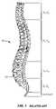
- FIG. 1is a lateral view of a normal human spinal column
- FIG. 2is a superior view of a normal human lumbar vertebra
- FIG. 3is a lateral view of a functional spinal unit
- FIG. 4is a postero-lateral oblique view of a vertebrae
- FIG. 5is a perspective view of the anatomical planes of the human body
- FIG. 6is a perspective view of a cephalad facet joint implantable device suitable for replacing the inferior half of a natural facet joint on a superior vertebral body;
- FIG. 7A-Bare views of one embodiment of a measurement tool for installing a cephalad facet joint
- FIGS. 8A , 8 B and 8 Care views of one embodiment of an installed measurement tool for an artificial cephalad facet joint
- FIG. 9is a perspective view of one embodiment of a caudad implantable device for replacing the superior half of a natural facet joint on an inferior vertebral body;
- FIGS. 10A and 10Bare views of one embodiment of a measurement tool for implanting an artificial caudad facet joint
- FIGS. 11A-Dare views of one embodiment of a measurement tool holder for holding a measurement tool for a caudad cephalad facet joint;
- FIGS. 12A and 12Bare views of one embodiment of an installed measurement tool for a caudad cephalad facet joint
- FIGS. 13A-Bare views of another embodiment of a measurement tool for a caudad facet joint
- FIGS. 14A-Care views of a measurement tool for a caudad facet joint
- FIGS. 15A-Dare views of a measurement tool illustrating the interior component of a measurement tool for a caudad facet joint
- FIGS. 16is an exploded view of an alternative embodiment of a measurement tool according to the invention.
- FIGS. 17A-Care views of a tool for implanting the measurement tool of the invention.
- FIGS. 18A-Dillustrate a measurement tool of the invention along with guides used with the measuring tool to assess the size and angle of the device to be implanted;
- FIGS. 19Aillustrates an image taken of a section of spine with the measurement tool incorporated therein to provide radiopaque markers
- FIGS. 19Billustrates a spine having two measurement tools associated therewith
- FIGS. 20Aillustrates a radiological image of a caudad selection tool in combination with a sizing template
- FIGS. 20Billustrates a portion of the spine with the measurement tools extending therefrom
- FIGS. 21illustrates a superior view of a vertebral body with a measurement tool associated therewith and a radiological image of the measurement tool within the spine;
- FIGS. 22illustrates a side view of vertebral body with two measurement tools associated therewith and a radiological image of the tool within the spine;
- FIG. 23is a flow chart illustrating method steps for determining the size of an artificial facet joint using the tools of the invention.
- the inventionrelates to tools for use with implantable devices, including implantable prosthesis suitable for implantation within the body to restore and/or augment connective tissue such as bone, and systems and methods for treating spinal pathologies that incorporate use of the tools.
- the inventionrelates generally to implantable devices and tools for use with implantable devices and apparatuses or mechanisms that are suitable for implantation within a human body to restore, augment, and/or replace soft tissue and connective tissue, including bone and cartilage, and systems for treating spinal pathologies.
- the implantable devices used with the toolscan include devices designed to replace missing, removed or resected body parts or structure.
- the implantable devices, tools, apparatus or mechanismsare configured such that the devices or tools can be formed from parts, elements or components which alone, or in combination, comprise the device or tools.
- the toolscan be configured to work with implantable devices formed from parts, elements or components.
- the implantable devicescan also be configured such that one or more elements or components are formed integrally to achieve a desired physiological, operational or functional result such that the components complete the device.
- toolscan be configured such that one or more elements or components are formed integrally to achieve a desired physiological, operational or functional result such that the components complete the tool.
- Functional resultscan include the surgical restoration and functional power of a joint, controlling, limiting or altering the functional power of a joint, and/or eliminating the functional power of a joint by preventing joint motion.
- Portions of the devicecan be configured to replace or augment existing anatomy and/or implanted devices, and/or be used in combination with resection or removal of existing anatomical structure.
- the tools of the inventionare designed to interact with the human spinal column 10 , as shown in FIG. 1 , which is comprised of a series of thirty-three stacked vertebrae 12 divided into five regions.
- the cervical regionincludes seven vertebrae, known as C1-C7.
- the thoracic regionincludes twelve vertebrae, known as T1-T12.
- the lumbar regioncontains five vertebrae, known as L1-L5.
- the sacral regionis comprised of five fused vertebrae, known as S1-S5, while the coccygeal region contains four fused vertebrae, known as Co1-Co4.
- FIG. 2depicts a superior plan view of a normal human lumbar vertebra 12 .
- human lumbar vertebraevary somewhat according to location, the vertebrae share many common features.
- Each vertebra 12includes a vertebral body 14 .
- Two short boney protrusions, the pedicles 16 , 16 ′,extend dorsally from each side of the vertebral body 14 to form a vertebral arch 18 which defines the vertebral foramen.
- each pedicle 16At the posterior end of each pedicle 16 , the vertebral arch 18 flares out into broad plates of bone known as the laminae 20 .
- the laminae 20fuse with each other to form a spinous process 22 .
- the spinous process 22provides for muscle and ligamentous attachment.
- a smooth transition from the pedicles 16 to the laminae 20is interrupted by the formation of a series of processes.
- Two transverse processes 24 , 24 ′thrust out laterally, one on each side, from the junction of the pedicle 16 with the lamina 20 .
- the transverse processes 24 , 24 ′serve as levers for the attachment of muscles to the vertebrae 12 .
- the superior articular processes 26 , 26 ′are sharp oval plates of bone rising upward on each side of the vertebrae, while the inferior processes 28 , 28 ′ are oval plates of bone that jut downward on each side. See also FIG. 4 .
- the superior and inferior articular processes 26 and 28each have a natural bony structure known as a facet.
- the superior articular facet 30faces medially upward, while the inferior articular facet 31 (see FIG. 3 ) faces laterally downward.
- the facets 30 and 31capped with a smooth articular cartilage and encapsulated by ligaments, interlock to form a facet joint 32 .
- the facet jointsare apophyseal joints that have a loose capsule and a synovial lining.
- the facet joint 32is composed of a superior facet 30 and an inferior facet 31 (shown in FIG. 4 ).
- the superior facetis formed by the vertebral level below the joint 32
- the inferior facetis formed in the vertebral level above the joint 32 .
- the superior facet of the joint 32is formed by bony structure on the L5 vertebra (i.e., a superior articular surface and supporting bone 26 on the L5 vertebra)
- the inferior facet of the joint 32is formed by bony structure on the L 4 vertebra (i.e., an inferior articular surface and supporting bone 28 on the L4 vertebra).
- the angle formed by a facet joint located between a superior facet and an inferior facetchanges with respect to the midline of the spine depending upon the location of the vertebral body along the spine.
- the facet jointsdo not, in and of themselves, substantially support axial loads unless the spine is in an extension posture (lordosis).
- the orientation of the facet joint for a particular pair of vertebral bodieschanges significantly from the thoracic to the lumbar spine to accommodate a joint's ability to resist flexion-extension, lateral bending, and rotation.
- FIG. 4illustrates a posterolateral oblique view of a vertebrae 12 , further illustrating the curved surface of the superior articular facet 30 and the protruding structure of the inferior facet 31 adapted to mate with the opposing superior articular facet.
- the position of the inferior facet 31 and superior facet 30varies on a particular vertebral body to achieve the desired biomechanical behavior of a region of the spine.
- the overall spinecomprises a series of functional spinal units that are a motion segment consisting of two adjacent vertebral bodies, the intervertebral disc, associated ligaments, and facet joints.
- functional spinal unitsthat are a motion segment consisting of two adjacent vertebral bodies, the intervertebral disc, associated ligaments, and facet joints.
- a natural facet jointsuch as facet joint 32 ( FIG. 3 ) has a superior facet 30 and an inferior facet 31 .
- the superior facet of the jointis formed by the vertebral level below the joint, which can thus be called the “caudad” portion of the facet joint because it is anatomically closer to the tail bone or feet of the person.
- the inferior facet of the facet jointis formed by the vertebral level above the joint, which can be called the “cephalad” portion of the facet joint because it is anatomically closer to the head of the person.
- a device that, in use, replaces the caudad portion of a natural facet jointi.e., the superior facet 30
- a device that, in use, replaces the cephalad portion of a natural facet jointi.e., the inferior facet 31
- a cephalad devicea device that, in use, replaces the cephalad portion of a natural facet joint.
- embodiments of the spinal devices of the present inventioninclude modular designs that are either or both configurable and adaptable.
- the various embodiments disclosed hereinmay also be formed into a kit or system of modular tools that can be assembled in situ to create a patient specific tool.
- imaging technologyimproves, and mechanisms for interpreting the images (e.g., software tools) improve, patient specific designs employing these concepts may be configured or manufactured prior to the surgery.
- patient specific deviceswith integrally formed components that are pre-configured.
- the practice of the present inventionemploys, unless otherwise indicated, conventional methods of x-ray imaging and processing, x-ray tomosynthesis, ultrasound including A-scan, B-scan and C-scan, computed tomography (CT scan), magnetic resonance imaging (MRI), optical coherence tomography, single photon emission tomography (SPECT) and positron emission tomography (PET) within the skill of the art.
- CT scancomputed tomography
- MRImagnetic resonance imaging
- SPECTsingle photon emission tomography
- PETpositron emission tomography
- a configurable modular device designallows for individual components to be selected from a range of different sizes and utilized within a modular device.
- sizeis to provide caudad and cephalad stems of various lengths.
- a modular implantable device designallows for individual components to be selected for different functional characteristics as well.
- One example of functionis to provide stems having different surface features and/or textures to provide anti-rotation capability.
- Other examples of the configurability of modular implantable device of the present inventionas described in greater detail below.
- Implantable devicescan be configurable such that the resulting implantable spinal device is selected and positioned to conform to a specific anatomy or desired surgical outcome.
- the adaptable aspect of devicesprovide the surgeon with customization options during the implantation or revision procedure. It is the adaptability of the device systems that also provides adjustment of the components during the implantation procedure to ensure optimal conformity to the desired anatomical orientation or surgical outcome.
- An adaptable modular deviceallows for the adjustment of various component-to-component relationships.
- One example of a component-to-component relationshipis the rotational angular relationship between a crossbar mount and a crossbar in an implantable device. Configurability may be thought of as the selection of a particular size of component that together with other component size selections results in a custom fit implantable device.
- Adaptabilitythen can refer to the implantation and adjustment of the individual components within a range of positions in such a way as to fine tune the “custom fit” devices for an individual patient.
- the net resultis that embodiments of the modular, configurable, adaptable spinal device and systems of the present invention allow the surgeon to alter the size, orientation, and relationship between the various components of the device to fit the particular needs of a patient during the actual surgical procedure.
- Tools that are configurable and adaptable in a manner similar to the devicesare contemplated by the invention to achieve optimal device selection for a patent.
- anatomical references of the body 50with respect to which the position and operation of the devices, and components thereof, are described.
- devices, tools, and the operation of devices and toolsare better understood with respect to the caudad 60 direction and/or the cephalad direction 62 .
- Devices positioned within the bodycan be positioned dorsally 70 (or posteriorly) such that the placement or operation of the tools or device is toward the back or rear of the body.
- devicescan be positioned ventrally 72 (or anteriorly) such that the placement or operation of the tool or device is toward the front of the body.
- Various embodiments of the spinal devices, tools and systems of the present inventionmay be configurable and variable with respect to a single anatomical plane or with respect to two or more anatomical planes.
- a component or toolmay be described as lying within and/or having adaptability or operability in relation to a single plane.
- a stemmay be positioned in a desired location relative to an axial plane and may be moveable between a number of adaptable positions or within a range of positions.
- the various componentscan incorporate differing sizes and/or shapes in order to accommodate differing patient sizes and/or anticipated loads.
- FIG. 6shows an artificial cephalad facet joint 40 configured to replace the inferior articulating process of a facet joint 31 , such as after the surgical removal of the articulating process.
- the cephalad facet joint 40is attached to a vertebra, the artificial facet joint element 44 articulates with the superior half of the facet joint 32 .
- artificial facet joint 40includes an artificial facet joint element 44 connected to a fixation element 52 via a polyaxial connection 41 that permits facet joint element 44 and fixation element 52 to be rotated with respect to each other around more than one axis.
- a fixing nut 48is threadably engaged with the outer periphery of base 42 above the artificial facet joint element 44 .
- a set screw 46is threadably engaged with the inner periphery of base 42 above the artificial facet joint element 44 .
- the artificial facet joint element 44includes a support arm 72 and a facet joint bearing surface 74 . In alternative embodiments, other convex or concave shapes may be used for the facet joint bearing surface 74 .
- Bearing surface 74may be formed from biocompatible metals (such as cobalt chromium steel, surgical steels, titanium, titanium alloys, tantalum alloys, aluminum, etc.), ceramics, polyethylene, biocompatible polymers, and other materials known in the orthopedic arts.
- Fixation element 52may be a screw, stem, corkscrew, wire, staple, adhesive, bone, and other materials known in the orthopedic arts.
- a measurement tool 400 suitable for use in installing and configuring the artificial facet joint 40 of FIG. 6includes a support arm element 401 and a fixation measurement element 402 via a polyaxial connection element 403 .
- the polyaxial connection element 403permits movement of the support arm element 401 along the fixation measurement element 402 in multiple axes.
- the connection 403permits vertical movement of the support arm element 401 along the fixation measurement element 402 (or fixation element) and also permits horizontal movement of the support arm element 401 relative to the fixation measurement element 402 .
- the measurement toolcontains aspects of the actual artificial facet joint 40 . Measurement tools optimized to aid in the implantation of other implantable spinal devices may have other features containing aspects of those devices.
- the fixation measurement element 402is adapted and configured to permit measurement of the length of a fixation element of an artificial cephalad facet joint to be installed in a patient.
- markings 407are present on the fixation measurement element 402 which permit the determination of this length measurement.
- a hole or cavityis formed in the vertebra of the patient at a location wherein the artificial cephalad facet joint 40 is intended to be installed and the measurement tool 400 is placed in this hole.
- the tool 400is adjusted to a position similar to that of the artificial cephalad facet joint, and then the penetration depth of the fixation measurement element 402 into the hole is determined. This penetration depth assists the user in choosing the length of the fixation element required to attach the artificial cephalad facet joint to the vertebra.
- the fixation measurement element 402includes indentations 411 such as those depicted in FIG. 7A .
- the indentations 409provide stops for the vertical movement of the support arm 401 along the fixation measurement element 402 , e.g., by engaging a ridge 411 in a support arm 401 .
- the indentations 409can also permit the determination of the length of the fixation element 52 of an artificial cephalad facet joint 40 to be installed in a patient.
- the indentations 409may be formed at intervals corresponding to various fixation stems or screw lengths contained in a modular component kit.
- another length measurementcan be obtained using the support arm element 401 .
- the support arm 401is positioned into a location wherein the artificial facet joint element 44 of the artificial cephalad facet joint 40 would be located.
- the distance between the fixation measurement element 402 and the putative location of facet joint bearing surface 74 of the artificial cephalad facet joint 40is measured along the support arm element 401 .
- This measurementis used to select the length of the support arm 72 of the cephalad facet joint 40 to be implanted in a patient.
- the measurementcould correspond to a color coding or number/letter designation that is used to determine the appropriate correspondingly-identified artificial facet joint.
- a trial facet joint bearing surface 404can be attached to the support arm element 401 .
- the trial facet joint bearing surface 404may be placed in the location that the actual artificial cephalad facet joint 40 would be placed and then the length measurement can be obtained which can be used to select the length of the support arm 72 of the artificial cephalad facet joint 40 .
- the relationship between the measurement tool's fixation measurement element, support arm element and trial facet joint bearing surfacecorresponds to aspects of the actual facet joint whose implant the tool is assisting.
- Other measurement tools and methods having aspects corresponding to other spine implant featuresare within the scope of this invention.
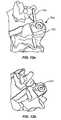
- FIG. 8shows different views of a measurement tool 400 placed into a vertebra 12 .
- the cephalad measurement tool 400can be placed in one vertebra and a caudad facet joint 600 can be placed in the inferior adjoining vertebra, as depicted in FIG. 8A .
- the artificial caudad facet jointcan be a trial device or the actual artificial facet joint.
- the support arm element 401When the measurement tool 400 is used with an artificial caudad facet joint, it is preferred that the support arm element 401 have a trial facet joint bearing surface 404 .
- a holeis formed in the location on the spine where the actual artificial cephalad facet joint 40 (not shown) is to be placed.
- the tool 400is placed in the hole formed in the spine at a depth that is similar to the depth at which actual artificial cephalad facet joint 40 is to be placed.
- the support arm 401is moved horizontally and/or vertically with respect to the fixation measurement element 402 and placed at about the same location that the artificial facet joint element 44 would be placed.
- the measurement tool 400includes a trial cephalad facet joint bearing surface 404 and is used in combination with an artificial caudad facet joint 600 , the trial facet joint bearing surface 404 is placed in the bearing surface of the caudad facet joint prior to taking the measurements.
- a window on the trial facet joint bearing surface 404can be used to read the length from the support arm element 401 .
- the length of the fixation element 52can be determined from the fixation measurement element 402 .
- Markings 407 and/or indentations 409 on the fixation measurement element 402can be used to determine the required length of the fixation element 52 .
- Markings 407are positioned to correspond with indentations on the fixation measurement element 402 such that when the polyaxial connection element 403 is engaged with the measurement element 402 , e.g., by engaging the indentation 405 in the fixation measurement element 402 with a ridge 402 a protrusion on the polyaxial connection element 403 , a measurement is ascertainable by the user.
- FIG. 9shows an artificial caudad facet joint 100 configured to replace the superior portion of a natural facet joint 30 , such as after the surgical removal of the articulating process forming the superior portion of the facet joint.
- Artificial caudad facet 100includes an artificial facet joint element 104 connected to a fixation element 116 via a polyaxial connection 115 that permits facet joint element 104 and fixation element 116 to be rotated with respect to each other around more than one axis.
- the polyaxial connection 115 of artificial caudad facet joint 100includes a base 112 connected to a support arm 102 of facet joint element 104 .
- the artificial facet joint element 104includes a bearing surface 118 .
- a fixing nut 108is threadably engaged with the outer periphery of base 112 above the artificial facet joint element 104 .
- a set screw 106is threadably engaged with the inner periphery of base 112 above the artificial facet joint element 104 .
- FIGS. 10-12depict one embodiment of a measurement tool for installing an artificial caudad facet joint 100 .
- the measurement toolcan be used to assist in the installation of artificial caudad facet joint such as those described in U.S. Patent Pub. US 2005/0131406 A1 (Reiley, et al.) or other caudad facet joint.
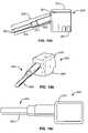
- Measurement tool 700suitable for use with the artificial caudad facet joint shown in FIG. 9 is shown in FIGS. 10A and 10B .
- Measurement tool 700includes a stem element 701 connected to a trial caudad bearing surface 702 via a fastener 703 .
- measurement tool 700contains aspects of the artificial caudad facet joint 100 whose implant the tool is assisting.
- the fastener 703is a set screw.
- other suitable fastenerscan be employed, including, but not limited to, stems, posts, threads, polyaxial mechanisms, splines, cap screws, ball detents, friction fits, tapers, press fits, bayonet, cams, collets and/or clamps.
- the stem element 701is adapted and configured to obtain length measurements which would correspond to the length of the fixation element 116 of the artificial caudad facet joint 100 .
- the stem element 701can include markings and/or indentations such as those depicted with respect to the cephalad tool 400 shown in FIG. 8 to assist in obtaining the measurements. If desired, multiple stem elements of varying diameters and lengths can be utilized in a similar fashion to size and/or determine the diameter and dimensions of the hole or cavity.
- the trial caudad bearing surface 702helps determine the relative positions of, and the angle between, the artificial facet joint's fixation element and its bearing surface.
- the trial caudad bearing surface 702is capable of movement along multiple planes and can rotate relative to the stem element 701 via a lockable ball-joint or other suitable joint configuration. If desired, an alternate embodiment of the bearing surface 702 can move vertically (not shown) along the stem element 701 , to permit sizing of the stem element 701 . Other planes of movement can include the median, horizontal and frontal planes as well as the sagittal, coronal, and axial shown in FIG. 5 . In another embodiment, the caudad bearing surface 702 is connected to a handle 704 .
- the handle 704allows the user to move the caudad bearing surface 702 into the desired location and also position it in the right plane. Typically, the handle 704 permits movement of the caudad bearing surface 702 in various planes for alignment. Also, the handle 704 can permit the user to place the stem 701 of the tool 700 into the hole drilled in the vertebra.
- the handle 704can comprise a radiopaque material with the handle 704 used for fluoroscopic alignment of the caudad bearing surface 702 .
- a physiciancan see the instrument when radiologic imaging techniques are used.
- the handle 704 and upper end plate of the caudad vertebral body(not shown) can be examined in a medial-lateral image (using non-invasive and/or fluoroscopic imagine apparatus) of the surgical area.
- a comparison of the orientation of the handle 704 and the orientation of the upper end platecan be made to determine the desired alignment and positioning of the caudad bearing surface.
- the orientation of the handle and the upper end platecan be parallel or nearly parallel.
- FIGS. 11A-DAnother aspect of the invention is a measurement tool holder for use with the caudad measurement tool 700 described above or another measurement tool.
- the measurement tool holder 800includes a measurement surface 801 and a holder element 802 .
- the measurement surface 801includes two plates attached to each other at a right angle, as illustrated in FIG. 11C-D .
- the measurement surface 801is adapted and configured to measure the angle between the caudad bearing surface 702 and stem 701 . This angle measurement is typically used by a user to select, assemble and/or configure an artificial caudad facet joint 100 for implantation into a patient, such as artificial caudad facet joint 100 of FIG. 9 .
- the selected artificial caudad facet joint 100may have an angle measurement between its bearing surface 118 and its fixation element 116 similar to the angle measurement obtained from the caudad measurement tool 700 and measurement tool holder 800 .
- the artificial caudad facet jointmay be configurable to orient its fixation element 116 and its bearing surface 118 to match the measured angle.
- the tool holder's 800 measurement surface 801includes markings 803 to assist in obtaining the desired angle measurements.
- the top surface of the measurement surface 801may have a holder element 802 attached thereto.
- the holder element 802can be, for example, a square or rectangular block with a portion of the block cut-out to fit the caudad bearing surface 702 of the caudad measurement tool 700 .
- the blockcan be configured to engage the measurement tool 700 the portion of the holder element 802 that holds the caudad bearing surface 702 is cut-out in a shape that is suitable for holding the caudad bearing surface 702 .
- the shape of the cut-out portion of the holder element 802will vary depending on the shape of the caudad bearing surface 702 to be used with the measurement holder 800 .
- One aspect of the inventionis a method for using the caudad measurement tool 700 in combination with, for example, the measurement tool holder 800 described above or with the cephalad measurement tool 400 described above.
- a holeis formed at a suitable location in the vertebra (such as by drilling) wherein an artificial caudad facet joint 100 is intended to be placed. This location typically is the best location for the placement of the artificial caudad facet joint based on the condition of the bone, easy access to the location, etc.
- the caudad measurement tool 700is placed in a manner as shown in FIGS. 12A and 12B .
- the caudad measurement tool 700may be placed into the hole using the handle 704 .
- the handle 704 and the set screw 703are used to place the measurement tool at the required depth and also to place the caudad bearing surface 702 at the required angle.
- the fastener 703is loosened and the caudad bearing surface 702 is positioned at the appropriate angle.
- the fastener 703is tightened to maintain the angle for measurement purposes.
- the caudad measurement tool 700is used in combination with an artificial cephalad facet joint (such as artificial cephalad facet joint 40 described above) or a cephalad measurement tool (such as tool 400 described above).
- an artificial cephalad facet joint or a cephalad measurement toolWhen used in combination with an artificial cephalad facet joint or a cephalad measurement tool, the caudad bearing surface 702 is placed in contact with the facet joint bearing surface of the artificial cephalad facet joint or the trial facet joint bearing surface. Then, the position of the caudad bearing surface 702 is adjusted by manipulating the fastener 703 (as described above) to get good articulation with the facet joint bearing surface or the trial facet joint bearing surface.
- the length and angle measurementsare obtained.
- the caudad measurement tool 700is removed from the hole to take the measurements.
- One of the measurements that can be obtained with the caudad measurement tool 700is the fixation length measurement. This measurement is obtained from the stem element 701 and indicates the length of the fixation element 116 of the artificial caudad facet joint to be implanted in a patient.
- the caudad measurement tool 700can be used to obtain an angle measurement between the caudad bearing surface 702 (or alignment fixation measurement) and stem element 701 . This measurement may be obtained by placing the caudad measurement tool 700 into a measurement tool holder (such as holder 800 described above) and reading the angle, such as from a measuring surface 801 .
- this angle measurementis used to determine the angle between the artificial facet joint element 104 and fixation element 116 of the artificial caudad 100 .
- the caudad bearing surfaceis positioned and secured to the vertebral body first, and then the cephalad bearing surface is positioned and secured relative to the caudad bearing surface.
- One aspect of the inventionis a method for selecting suitable caudad and/or cephalad artificial joints from a set of artificial joints for implantation into a patient.
- the cephalad measurement tool 400is used to obtain the two length measurements from the fixation measurement 402 and support arm 401 .
- a useruses these measurements to select a suitable artificial cephalad facet joint 40 for implantation in a patient.
- the selected artificial facet jointpreferably has a fixation element 52 length and support arm 72 length that are similar to the support arm 401 and fixation measurement 402 length measurements, respectively, obtained from the cephalad measurement tool 400 .
- similarincludes lengths that have values that correspond to each other but are not necessarily identical.
- the caudad measurement tool 700is used to obtain length and angle measurements and a user uses these measurements to select a suitable artificial cephalad facet joint for implantation in a patient.
- the selected artificial facet jointpreferably has a stem 701 length similar to the length measurement from the caudad tool 700 and has an angle between the artificial facet joint element and fixation element similar to the angle measurement obtained from the tool.
- FIGS. 13A-BYet another alternate device and method for determining the proper size and orientation of the artificial facet joint is illustrated in FIGS. 13A-B .
- a toolsuch as a component selection instrument 1300 is illustrated that is useful for determining the proper combination of caudad anchor stem, as well as the caudad cup best suited for a targeted anatomy.
- a component selection instrument 1300comprises a handle 1310 , a body 1320 and a stem 1330 , each of these preferably comprising a radiolucent material.
- radiopaque markers 1350 , 1360 and 1370are positioned, such that, when the stem 1340 is inserted into a pilot hole (not shown) of a targeted vertebral body in a spine, upon radiographic visualization of the vertebral body, the radiopaque markers align to indicate the proper combination of components for the targeted region, while the radiolucent instrument allows the physician to view the markers relative to the patient's anatomy.
- a component selection instrument 1300incorporates a distal radiopaque marker 1350 positioned within the distal tip 1340 of the stem 1330 .
- a series of stem selection radiopaque markers 1360are positioned within the housing. As will be appreciated by those skilled in the art, more or fewer markers can be used.
- a series of cup selection radiopaque markers 1370are also positioned within the housing.
- the component selection instrument 1300can be optimized for single-sided use (for measurement of only the left or right pedicle) or for dual-sided use (for example, the component selection instrument could be adapted and configured to incorporate symmetrical radiopaque markers that provide the proper measurements depending upon the orientation of the instrument. Additionally, as discussed more fully below, the markers can be given exterior dimensions that present different profiles during radiography in order to facilitate an ease in determining which set of markers is being viewed.
- the interior edge 1380 of the housing 1320(the edge nearest the centerline or midline of the spine in the body (see FIG. 5 )) is visually aligned with the spinous process 22 of the vertebral body (see FIGS. 1-4 ).
- radiologic techniques known in the artcan be used to obtain a view of the target anatomy along with the component selection instrument, such as an anterior/posterior (A/P) view of the spine and component selection instrument 1300 using a fluoroscope.
- A/Panterior/posterior
- the distal radiopaque marker 1350will line-up with (or will appear closest to) one of the stem selection radiopaque markers 1360 , each of which correspond to a different stem angle.
- the physiciancan then take a lateral view of the spine and component selection instrument 1300 . From the lateral view, the physician can then align the cephalad endplate of the caudad vertebral body (not shown) with the most appropriate cup selection radiopaque marker, which gives the proper cup size for implantation. (See, FIG. 23 ).
- a lateral viewcan be taken first, or only one of the A/P or lateral view can be taken and analyzed.
- the caudad stemmay be secured directly into the vertebral body, or can be attached and/or “fixed” using a supplemental fixation material such as bone cement, allograft tissue, autograft tissue, adhesives, osteo-conductive materials, osteo-inductive materials and/or bone scaffolding materials.
- the first fixation elementcan be enhanced with a bony in-growth surface, such as surfaces created using sintering processes or chemical etching (Tecomet Corporation of Woburn, Mass.) which can help fix the fixation element within a vertebra.
- the bony in-growth surfacecan cover all or a portion of the caudad fixation element.
- the final orientation of the caudad cups of-the caudad facet joint 600( FIGS. 8B and 9 ) will be parallel (relative to the lateral walls 159 of the caudad cup) and coplanar (with respect to the upper bottom surfaces 153 ).
- FIG. 14Adepicts a top plan view of an alternate embodiment of a component selection instrument 900 constructed in accordance with various teachings of the present invention.
- the component selection instrument 900comprises a stem 905 and a head 910 , both of which, in this embodiment, are desirably (but not necessarily) constructed of radio-lucent materials (or alternative materials useful in conjunction with the present invention, including those that desirably facilitate the use of non-direct visualization such as fluoroscopy, real-time CT scanning and/or real-time MRI).
- the stemcomprises a distal section 950 (distal from the block) having a distal end 951 , a central section 955 , and a proximal section 960 .
- the stem 905is configured to engage the head 910 at its proximal end 961 .
- the stem 950can be positioned such that it extends from the head 910 at an angle other than 90° in at least one direction.
- the head 910is positioned on a first geometric plane, while the stem 905 extends from the head 910 such that the stem 905 crosses, or could cross if the stem had sufficient length, the geometric plane on which the head 910 is positioned.
- FIG. 14 aa side view of the component selection instrument 900
- the head 910is positioned on a first geometric plane, while the stem 905 extends from the head 910 such that the stem 905 crosses, or could cross if the stem had sufficient length, the geometric plane on which the head 910 is positioned.
- FIG. 14Ca view of the instrument 900 taken from a top view, the stem 905 extends from the head 910 such that it appears from this two-dimensional perspective that the stem 905 and the head 910 lie within the same plane.
- FIG. 14Billustrates a perspective view of the instrument 900 .
- the head 910can be configured with an indentation, slot or keyway 990 which is adapted to engage a tool, such as the tool shown in FIG. 17 .
- one or more radiopaque markersare contained within the stem 905 and head 910 . These markers are desirably positioned such that, when the component selection instrument 900 is secured to the targeted vertebral body, one or more non-direct visualization methods can be used to compare the visible anatomical landmarks to the various markers incorporated in the component selection instrument (as well as the various inter-relationships between markers and/or the anatomical features themselves) to determine the anatomical characteristics of the components of the targeted vertebral body, as well as the relationship therebetween.
- This inventionallows the physician employ minimally invasive techniques to select the optimal implantable artificial joint components to accommodate the targeted patient anatomy.
- the unique orientation and positioning of the radiopaque markers within the stem 905 and head 910can obviate the need for an “adjustable,” or articulating, facet measurement devices, thereby significantly simplifying the construction and/or use of the device.
- the component selection instrument 900incorporates a radiopaque marker 915 positioned within the stem 905 .
- the radiopaque marker 915can be in a variety of suitable configurations, such as a ball, as depicted which would present a circular image in a two dimensional image, such as an x-ray.
- the radiopaque ball 915 and various marker elements in the head 910are arranged to allow determination of the orientation of the stem 905 relative to a given anatomical feature and/or arbitrary reference plane.
- a first marker 920can be positioned within the head 910 .
- this first marker 920can be used to determine the angle of the stem 905 relative to a cephalad endplate (not shown) of the vertebral body in which the component selection instrument is placed.
- One or more second markers 935 , 940 and 945(which may be parallel to each other and/or within the same plane) can also be positioned within the head 910 , and are desirably used, in conjunction with the ball 905 .
- first and second markerscan be used without departing from the scope of the invention.
- the first set of markerscan be in a first orientation, e.g.
- the second set of markerscan be in a second orientation that is different than that of the first set of markers, e.g. vertical, where horizontal and vertical can be in relation to a defined plane in the body or an arbitrary plane used to describe the location of one set of markers with respect to the second set of markers, given that the actual location of the component selection instrument within a human body can change depending upon the location in the spine where the instrument is used.
- Either or both sets of markersis useful for determining the orientation of the stem 905 in relation to a sagittal plane passing vertically through a targeted vertebral body (see, FIG. 5 ).
- the stem 905is configured to engage the head 910 by, for example, threadably engaging the proximal end of the stem 905 .
- the proximal end of the stem 905has a plurality of threads 906 that engage grooves 908 located within the head 910 .
- the stem 910can be configured such that it has a hollow aperture 912 through a portion thereof.
- the hollow aperturecan be used to house the distal end 950 of the stem 910 .
- a first pilot holecan be drilled into the vertebral body of a first diameter.
- the telescoping stem 910can then be inserted into the pilot hole a distance corresponding to the length of the distal end 950 of the stem 910 which has a diameter that is sized to engage the first pilot hole.
- a second pilot holecan be drilled which enlarges or revises the diameter of the first pilot hole and uses the first pilot hole as a basis.
- the stem 910can be reinserted into the pilot hole.
- the telescoping distal end 950can be retracted into the lumen of the proximal end of the stem enabling the larger diametered distal end to be inserted into the pilot hole.
- the pilot holecan be of sufficient depth to enable it to accommodate the entire length of the stem 910 , which the upper region of the pilot hole having a diameter sized to engage the larger diameter of the proximal end of the stem 910 .
- the stem 910is telescoping
- the stemcould be configured such that when extended, the distal end of the stem is maintained in an extended configuration by, for example, twisting the distal end relative to the proximal end to engage a latch (similar to a child-proof cap configuration).
- the distal end of the stemcould engage one or more detents which engage the distal end in an extended or retracted position.
- Other solutionswould be apparent to those of skill in the art without departing from the scope of the invention.
- the interior of the stem 910can be configured from a material that has a radiopacity that is different than the rest of the device (either more radiopaque, or less), thus providing additional visual markers for the physician upon taking an image, such as an x-ray (see, FIG. 15B ).
- the hardness of a first materiale.g. the interior material
- a component selection instrument 900can comprise an approximately 0.8′′ by 0.5′′ block of radio-lucent polymer, having an approximately 4.5 cm long stem extending outward from the block.
- the stem 905can be configured such that it is stepped by having sections along its lengths of different diameters (see, e.g. FIG. 15 ).
- the stem 905can gradually change from a first diameter at a first end to a second diameter at a second end by, for example, use of a slope or slant along the length of the stem.
- the polymer or thermoplastic used to make any of the components of the instrument 900can comprise virtually any non-radiopaque polymer well known to those skilled in the art including, but not limited to, polyether-etherketone (PEEK), polyphenylsolfone (Radel®), or polyetherimide resin (Ultem®).
- the polymermay also comprise a translucent or transparent material, or a combination of materials where a first material has a first radiopacity and the second material has a second radiopacity.
- Suitable PEEKcan include an unfilled PEEK approved for medical implantation such as that available from Victrex of Lancashire, Great Britain.
- the instruments and toolscan be formed by extrusion, injection, compression molding and/or machining techniques, as would be appreciated by those skilled in the art.
- Other polymersthat may be suitable for use in some embodiments, for example other grades of PEEK, such as 30% glass-filled or 30% carbon filled, provided such materials are cleared for use in implantable devices by the FDA, or other regulatory body.
- the use of glass filled PEEKwould be desirable where there was a need to reduce the expansion rate and increase the flexural modulus of PEEK for the instrument.
- Glass-filled PEEKis known to be ideal for improved strength, stiffness, or stability while carbon filled PEEK is known to enhance the compressive strength and stiffness of PEEK and lower its expansion rate.
- Still other suitable biocompatible thermoplastic or thermoplastic polycondensate materialsmabe be suitable, including materials that have good memory, are flexible, and/or deflectable have very low moisture absorption, and good weae and/or abrasion resistance, can be used without departing from the scope of the invention.
- Theseinclude polyetherketoneketone (PEKK), polyetherketone (PEK), polyetherketoneetherketoneketone (PEKEKK), and polyetheretherketoneketone (PEEKK), and generally a polyaryletheretherketone.
- thermoplastic materialssuch as Bionate®, polycarbonate urethane, available from the Polymer Technology Group, Berkeley, Calif., may also be appropriate because of the good oxidative stability, biocompatibility, mechanical strength and abrasion resistance.
- Other thermoplastic materials and other high molecular weight polymerscan be used as well for portions of the instrument that are desired to be radiolucent.
- the stem 905comprises a 2.25 cm long distal section having a 4.5 mm diameter, which transitions to a 0.75 cm long central section having a 5.75 mm diameter, and then transitions to a 2.0 cm long proximal section having a 6.5 mm diameter.
- Other configurationsare possible, including configurations having other lengths, diameters, as well as fewer or more stepped sections.
- the radiopaque ball 915(which could comprise, for example, a 2 mm diameter stainless steel ball) is desirably secured inside the central section 955 of the stem.
- the various first and second set of radiopaque markers 920 , 935 , 940 and 945can comprise, for example, 1.5 mm diameter sections of 1 cm long stainless steel wire having a smooth outer surface.
- the component selection instrumentcan be configured to present a first set of radiopaque markers 920 at a first orientation and a second set of radiopaque markers 935 , 940 , 945 at a second orientation.
- the first set of radiopaque markers 920lie in a first plane and are positioned parallel one another; while the second set of radiopaque markers 935 , 940 , 945 lie in a second plane that is orientated perpendicular to the first plane.
- FIG. 15Cis a top view of the component selection instrument 900 where the first set of radiopaque markers 920 appear as circles due to the orientation, while the second set of radiopaque markers 935 , 940 , 945 appear as rods or lengths of wire.
- FIG. 15Cis a top view of the component selection instrument 900 where the first set of radiopaque markers 920 appear as circles due to the orientation, while the second set of radiopaque markers 935 , 940 , 945 appear as rods or lengths of wire.
- the first set of radiopaque markers 920are configured such that the markers are not parallel one another, while the second set of radiopaque markers are parallel such that in this orientation and from the perspective shown it appears as though there is only one marker although, in fact, more than one marker may be present, but may not be readily apparent because the markers are stacked in two dimensions.
- the various stem diametersdesirably facilitate and accommodate measurement and verification of proper component sizes during the various stages of facet replacement surgery.
- the surgeonmay drill a first pilot hole, e.g. a 4.5 mm passage, into and/or through the pedicle.
- This small diameter passagewhich may be too small to properly accommodate the anchoring device of an artificial facet joint (depending on the diameter and type of anchoring device), is well suited for implantation of a standard commercially-available pedicle screw fusion system (such as the UCR Pedicle Screw System from SeaSpine (information available at http://www.seaspine.com/ UCR_Pedicle_Screw_System.html)).
- the 4.5 mm distal portion of the stem 910 of the component selection instrument 900will fit into the 4.5 mm passage drilled into the pedicle, and if the measurement obtained using the component selection instrument indicates that the passage through the vertebral anatomy cannot be accommodated by the components of the artificial facet joint, the surgeon can then choose to (1) redrill or revise the passage and remeasure the passage (e.g., by boring out the original pilot hole with a larger diameter passage and then inserting the component selection instrument into the revised pilot hole), (2) implant the components of the artificial facet joint most closely approximating the anatomy, and/or (3) choose to fuse the targeted spinal level and implant a pedicle screw and rod system.
- the present measurement systemallows the physician to discontinue the facet joint replacement procedure where the anatomy and/or available artificial facet joint components cannot accommodate the targeted spinal level.
- the component selection instrumentcan be removed, the passage can then be redrilled (if desired) to a larger diameter (in this embodiment, either 5.75 mm or 6.5 mm), and remeasured (if desired) using the larger diameter section of the stem to secure the component selection instrument within the newly drilled passage to ensure proper choice in artificial facet joint components.
- the artificial facet jointcan then be implanted.
- FIG. 16illustrates yet another embodiment wherein the component selection instrument is exploded and markers (e.g., first set of radiopaque markers 920 or second set of radiopaque markers 935 , 940 , 945 ) are configured such that the exterior of the radiopaque marker does not present a smooth surface (e.g. markers illustrated previously appear as either a smooth wire or bar (defined by two parallel lines when sitting longitudinally in a first plane as captured by an image) or a circle (representing the diameter of the marker as it appears in a plane 90° offset from the first plane).
- markerse.g., first set of radiopaque markers 920 or second set of radiopaque markers 935 , 940 , 945
- markerse.g., first set of radiopaque markers 920 or second set of radiopaque markers 935 , 940 , 945
- markerse.g., first set of radiopaque markers 920 or second set of radiopaque markers 935 , 940 , 9
- a single first marker 920is employed with three second markers 935 , 940 , 945 oriented in a plane perpendicular, or substantially perpendicular to the first marker 920 . While the alternate configuration of marker could be used, it would also be advantageous to mix the marker profiles within a single component selection instrument such that the markers in a first orientation were, for example, smooth wire, while the markers in a second orientation are turned, e.g.
- the orientation of the component selection instrument relative to the anatomywould be easily determinable based on the appearance of smooth lines or turned, notched or etched surfaces along the length of a marker.
- the distal end of the stemis solid while the proximal end of the stem has an aperture 962 that is sized to receive the marker 915 and a tube 964 which fits within the aperture 962 and is sized to retain the marker within the stem 910 .
- the markers 920 , 935 , 940 , 945can be configured such that the markers in the first component selection tool have a first geometric profile, such as smooth lines, or turned, notched or etched surfaces along the length. While the markers 920 , 935 , 940 , 945 of the second component selection tool have a geometric profile that is not the same as the geometric profile of the markers 920 , 935 , 940 , 945 of the first component selection tool.
- markers 920 , 935 , 940 , 945 of the first component selection toolcould be smooth wire while markers 920 , 935 , 940 , 945 of the second component selection tool could be turned wire.
- a usercould assess by looking at a single image the desired size and configuration of a device for first and second target joint locations by knowing that type of markers in the first component selection tool and its location within the body and the type of markers in the second component selection tool and its location within the body.
- the component selection instrumentscould be positioned in a right and left half of a single vertebral body, or could be positioned within adjacent vertebral bodies.
- FIG. 17the component selection tool 900 of FIG. 15 is combined with a delivery tool 1000 such as a pair of forceps with a configured distal end for engaging the component selection tool 900 .
- a delivery tool 1000such as a pair of forceps with a configured distal end for engaging the component selection tool 900 .
- any instrument resembling a pair of pincers or tongs, used for grasping, manipulating, or extracting, that is adapted at an end to engage the component selection instrumentwould be suitable.
- Adapted forcepsare depicted for purposes of illustration.
- FIG. 17 aillustrates a perspective view of the forceps 1000 engaging the component selection instrument 900 .
- FIG. 17 billustrates the forceps 1000 engaging the component selection instrument 900 from a first planar view, while FIG.
- 17 cillustrates the forceps 1000 engaging the component selection instrument 900 from a second planar view.
- FIG. 18Aillustrates a perspective view of a component selection tool 1100 .
- the component selection tool 1100has a head 910 and a stem 905 configured differently than the component selection tool 900 of FIG. 14 .
- a variety of radiopaque markers 1102 , 1104 , 1106 , 1108are provided as shown in FIG. 18B .
- FIG. 18 cillustrates a gauge 1800 for use in determining cephalad arm length from an A/P view.
- the gauge 1800is calibrated to provide an indication of a known distance 1802 of the markers in the component selection instrument. From that point, a small region 1804 , medium region 1806 , and large region 1808 is also marked.
- the calibration gauge 1800can also be used in a similar manner with other joints.
- FIG. 18Danother gauge 1810 is provided.
- a first line 1812is oriented along a component selection instrument cephalad stem orientation line. From that point, the angle of the stem can be determined, e.g. 75°, 85
- FIG. 19Adepicts an A/P radiographic image 2000 of one embodiment of a component selection instrument 2010 positioned within a pedicle of a targeted vertebral body.
- the ball 2015is positioned between two radiopaque markers 2030 , 2035 nearest marker 2035 .
- FIG. 19Bis an image of a spinal column with two component selection instruments 2010 , 2010 ′ placed therein.
- FIG. 20Ais a lateral radiographic image 2100 of a spine with a component selection instrument 2110 associated therewith.
- a caudal selector lateral templateis used in conjunction with the image to assess the optimal orientation of the caudad selector. Values from ⁇ 9 to +11 are indicated 2112 . This assists in denoting the desired implant component (corresponding to that anatomical orientation of the vertebral body) which accommodates an axial angle (relative to the sagittal plane).
- a single A/P viewcan be utilized to characterize the pedicle of a single targeted vertebral body.
- a single A/P viewcan be utilized to characterize both pedicles of a single targeted vertebral body, each pedicle of which will incorporate a single component selector instrument.
- a single A/P viewcan be utilized to characterize the pedicles of multiple targeted vertebral bodies (adjacent or non-adjacent), with the pedicles of the vertebral bodies each incorporating a single component selector instrument.
- additional views from the same or different perspectivescan also be used without departing from the scope of the invention, including slices taken using an MRI.
- FIG. 20Billustrates an image of a portion of a spine model having a component selection instrument 2110 associated therewith.
- FIG. 21an image of a vertebral body from a superior position 2200 is illustrated having a midline 2202 .
- Three possible orientations 2206 of a stem 2204are illustrated at, e.g., 10°, 20° and 30°.
- a radiological image 2210 from a posterior viewillustrates the lines and circles of the markers corresponding to, in this instance a location of the circular marker between the innermost two marker lines which indicates a 30° angle to the midline 2202 .
- two component selection instrumentsare positioned within the vertebral body for selecting the caudad facet joint. The axial plane angles are measured for selecting a caudad facet joint.
- the physicianlocates the ball shaped marker 2215 , 2215 ′ of the component selection instrument. Due to the orientation of the marker 2215 , 2215 ′ to a second set of markers 2230 , 2235 , 2240 , which appear as vertical lines in the image, in the two dimensional plane the marker 2215 appears to be located between the lines formed by markers 2230 , 2235 , 2240 .
- Each of the markers 2230 , 2235 , 2240corresponds to an angle such that identifying the angle using the component selection instrument enables the physician to select an implant, such as a caudad facet joint, having an angled orientation that best matches the anatomy of the patient. As shown in FIG.
- the image depictedhas two component selection instruments 2201 , 2201 ′.
- the first component selection instrument 2201has marker 2215 between two markers positioned nearest the midline of the spine.
- the marker nearest the midline of the spinecorresponds to a 30° angle, thus the facet joint selected for the joint measured by component selection instrument 2201 is a 30° facet joint device.
- the second component selection instrument 2201 ′has marker 2215 positioned partially over the middle vertical marker.
- the middle vertical markercorresponds to a 20° angle, thus the facet joint selected for the joint measured by component selection instrument 2201 ′ is a 20° facet joint device.
- FIG. 22illustrates another image of a vertebral body from a side view 2300 .
- the spinous process 22is apparent as well as the superior facet joint 32 .
- the imageindicates that the size component would correspond to 11°.
- the ball marker 2315appears as a ball near the spine 12 in the image.
- the component selection instrument 2301 of this devicetwo different types of markers have been used as described above, smooth profiled wire, and turned wire with a curved profile.
- the first marker 2311 of the first component selection instrumentis a smooth wire
- the second marker 2311 ′ of the second component selection instrumentis a turned marker.
- a templateis lined up with the posterior wire 2320 and the distal face of the head 2310 at an axis 2313 .
- a series of linescan be measured to correspond to the appropriate angle of the device to be implanted. Three angle lines are depicted, +1, +6, +11. In selecting the angle, the line that corresponds to the top surface of the vertebral body associated with the component selection instrument is selected. In the image provided, the selection corresponds to the +11.
- the implantable spinal componentscan be selected from a group of modular components having dimensions and sizes which directly correspond to the various measurements determined from the component selection instrument (or can be marked with similar markings on the component and component selection/template).
- the vertical radiopaque markers on the component selection instrumentcould be marked 10°, 20° and 30° (which would desirably be visible on the radiographic image), and similar markings (10°, 20° and 30°) could appear on the corresponding modular components (in this embodiment, the modular stems) of the artificial facet joints.
- the templatecould incorporate markings for ⁇ 4°, ⁇ 9°, 1°, 6° and 11°, and similar markings ( ⁇ 4°, ⁇ 9°, 1°, 6° and 11°) could appear on the corresponding modular components (in this embodiment, the modular caudad cups) of the artificial facet joints.
- a single lateral imagecan desirably be utilized to determine the necessary characteristics of the targeted vertebral body(ies) as well.
- the component selection instrumentincorporates a single horizontal marker, which can be seen on the radiographic image.
- a clear or translucent templatesuch as described above with respect to FIG. 22 , can be placed over the radiographic image (or against the monitor screen, in the case of real-time fluoroscopy), and the angle between the upper endplate (or other desired anatomical feature) and the marker can be assessed visually with the template.
- the physiciancan then choose the implant component which corresponds to that measurement.
- a single lateral viewcan be utilized to characterize the pedicle of a single targeted vertebral body.
- a single lateral viewcan be utilized to characterize both pedicles of a single targeted vertebral body, each pedicle of which will incorporate a single component selection instrument.
- a single lateral viewcan be utilized to characterize the pedicles of multiple targeted vertebral bodies (adjacent or non-adjacent), with the pedicles of the vertebral bodies each incorporating a single component selection instrument.
- the component selector instrument(s)will, when properly positioned, allow the physician to take a single lateral radiographic image, and/or a single anterior/posterior (A/P) image, and determine the necessary characteristics of the targeted vertebral body(ies) to accurately choose components and construct a facet replacement construct with minimal time, effort and radiation exposure to the patient.
- A/Panterior/posterior
- the entirety of the component selection instrumentis contained within the wound, and desirably does not extend out of the wound opening, the disclosed measurement system significantly reduces the opportunity for the radiographic imaging apparatus to contact objects in the sterile field.
- one or more component selection instrumentscould be implanted, and then the surgical wound covered and/or closed, and imaging to occur, with no reduction in the ability of the apparatus to measure the anatomical characteristics of the surgical site.
- the disclosed anatomical measurement systemdetermines the anatomical measurements through comparisons of angular relationships and/or known distances, the disclosed system is desirably immune to the effects of magnification and/or distortion of the radiographic images (which can include unknown magnification of the radiographic images, varying monitor and/or print-out size, and/or inaccurate and/or out-of-date calibration of the imaging equipment itself).
- a physiciancan perform a surgical procedure (including surgical procedures that result in destabilization and/or damage to the spinal column and/or facet joints), and then prepare the surgical site for implantation of a facet joint replacement device.
- the surgeonwill drill a hole into each pedicle of the targeted vertebral body(ies), and then insert a component selection instrument into the hole.
- each component selection instrumentdesirably incorporates a reduced-width gripping section, which facilitates gripping and manipulation of the component selection instrument using a pair of surgical clamps or forceps, but allows the clamp to be removed during visualization, if desired, (as well as to reduce the size and “footprint” of the component selection instrument within the wound).
- the surgeonwill visually align the component selection instrument (using, for example, the lateral edge of the body, etc.) with the spinous process of the targeted vertebral body, or other desired anatomical landmark.
- the component selection instrumentscan be removed and implantation of the desired facet joint replacement components can be accomplished.
- a similar component selection instrumentcan be utilized.
- a component selection instrument best suited for measurement and characterization of cephalad componentsmay measure significantly different anatomical characteristics of the cephalad and/or caudad vertebral bodies.
- the radiolucent tool with radiopaque markersallows a surgeon to determine which angles are appropriate for the artificial orthopedic devices being inserted, such as the artificial caudad facet joint and the artificial cephalad facet joint described above.
- the surgeoncan determine the appropriate angle of device to use to achieve optimal results for the patient.
- the devicecan also be adjusted in situ to reference anatomical landmarks through direct visual means, or to allow the user to determine the most appropriate angle for viewing.
- FIG. 23illustrates a flow chart of a method for using the component selection tool.
- target anatomyis accessed, preferably in a minimally invasive fashion.
- a pilot holeis drilled 2400 , e.g. in the target vertebral body.
- the stem of the component selection instrumentis then inserted into the pilot hole 2402 .
- the depth to which the component selection tool may be inserted into the pilot holemay be effected, as discussed above.
- the depth at which the component selection tool is insertedcan be adjusted 2404 , if desired. Once sufficient depth is obtained 2406 , a radiologic image is taken of the patient 2408 using known techniques.
- the imageis then analyzed 2410 to determine the location of the markers in the component selection instrument relative to the target anatomy.
- the pilot holecan be revised 2411 to provide a pilot hole with a larger diameter after which another image can be taken (thus repeating step 2408 ).
- a suitable artificial jointcan be selected 2412 for the target anatomy.
Landscapes
- Health & Medical Sciences (AREA)
- Orthopedic Medicine & Surgery (AREA)
- Life Sciences & Earth Sciences (AREA)
- Biomedical Technology (AREA)
- Engineering & Computer Science (AREA)
- Neurology (AREA)
- Surgery (AREA)
- Heart & Thoracic Surgery (AREA)
- Animal Behavior & Ethology (AREA)
- General Health & Medical Sciences (AREA)
- Public Health (AREA)
- Veterinary Medicine (AREA)
- Transplantation (AREA)
- Nuclear Medicine, Radiotherapy & Molecular Imaging (AREA)
- Vascular Medicine (AREA)
- Oral & Maxillofacial Surgery (AREA)
- Cardiology (AREA)
- Molecular Biology (AREA)
- Medical Informatics (AREA)
- Physical Education & Sports Medicine (AREA)
- Biophysics (AREA)
- Surgical Instruments (AREA)
- Prostheses (AREA)
Abstract
Description
Claims (25)
Priority Applications (9)
| Application Number | Priority Date | Filing Date | Title |
|---|---|---|---|
| US11/236,323US7406775B2 (en) | 2004-04-22 | 2005-09-26 | Implantable orthopedic device component selection instrument and methods |
| EP06815178AEP1928366A1 (en) | 2005-09-26 | 2006-09-22 | Implantable orthopedic device component selection instrument and methods |
| AU2006294610AAU2006294610A1 (en) | 2005-09-26 | 2006-09-22 | Implantable orthopedic device component selection instrument and methods |
| PCT/US2006/036969WO2007038261A1 (en) | 2005-09-26 | 2006-09-22 | Implantable orthopedic device component selection instrument and methods |
| CA002623896ACA2623896A1 (en) | 2005-09-26 | 2006-09-22 | Implantable orthopedic device component selection instrument and methods |
| US12/099,068US20080287959A1 (en) | 2005-09-26 | 2008-04-07 | Measurement and trialing system and methods for orthopedic device component selection |
| US12/186,461US8675930B2 (en) | 2004-04-22 | 2008-08-05 | Implantable orthopedic device component selection instrument and methods |
| US14/165,122US9498260B2 (en) | 2004-04-22 | 2014-01-27 | Implantable orthopedic device component selection instrument and methods |
| US15/266,107US10064743B2 (en) | 2004-04-22 | 2016-09-15 | Implantable orthopedic device component selection instrument and methods |
Applications Claiming Priority (4)
| Application Number | Priority Date | Filing Date | Title |
|---|---|---|---|
| US10/831,651US7051451B2 (en) | 2004-04-22 | 2004-04-22 | Facet joint prosthesis measurement and implant tools |
| US64232105P | 2005-01-07 | 2005-01-07 | |
| US11/071,541US7674293B2 (en) | 2004-04-22 | 2005-03-02 | Crossbar spinal prosthesis having a modular design and related implantation methods |
| US11/236,323US7406775B2 (en) | 2004-04-22 | 2005-09-26 | Implantable orthopedic device component selection instrument and methods |
Related Parent Applications (2)
| Application Number | Title | Priority Date | Filing Date |
|---|---|---|---|
| US10/831,651Continuation-In-PartUS7051451B2 (en) | 2004-04-22 | 2004-04-22 | Facet joint prosthesis measurement and implant tools |
| US11/071,541Continuation-In-PartUS7674293B2 (en) | 1999-10-22 | 2005-03-02 | Crossbar spinal prosthesis having a modular design and related implantation methods |
Related Child Applications (2)
| Application Number | Title | Priority Date | Filing Date |
|---|---|---|---|
| US12/099,068Continuation-In-PartUS20080287959A1 (en) | 2005-09-26 | 2008-04-07 | Measurement and trialing system and methods for orthopedic device component selection |
| US12/186,461DivisionUS8675930B2 (en) | 2004-04-22 | 2008-08-05 | Implantable orthopedic device component selection instrument and methods |
Publications (2)
| Publication Number | Publication Date |
|---|---|
| US20060085072A1 US20060085072A1 (en) | 2006-04-20 |
| US7406775B2true US7406775B2 (en) | 2008-08-05 |
Family
ID=37681689
Family Applications (4)
| Application Number | Title | Priority Date | Filing Date |
|---|---|---|---|
| US11/236,323Expired - LifetimeUS7406775B2 (en) | 2004-04-22 | 2005-09-26 | Implantable orthopedic device component selection instrument and methods |
| US12/186,461Active2026-10-28US8675930B2 (en) | 2004-04-22 | 2008-08-05 | Implantable orthopedic device component selection instrument and methods |
| US14/165,122Expired - LifetimeUS9498260B2 (en) | 2004-04-22 | 2014-01-27 | Implantable orthopedic device component selection instrument and methods |
| US15/266,107Expired - LifetimeUS10064743B2 (en) | 2004-04-22 | 2016-09-15 | Implantable orthopedic device component selection instrument and methods |
Family Applications After (3)
| Application Number | Title | Priority Date | Filing Date |
|---|---|---|---|
| US12/186,461Active2026-10-28US8675930B2 (en) | 2004-04-22 | 2008-08-05 | Implantable orthopedic device component selection instrument and methods |
| US14/165,122Expired - LifetimeUS9498260B2 (en) | 2004-04-22 | 2014-01-27 | Implantable orthopedic device component selection instrument and methods |
| US15/266,107Expired - LifetimeUS10064743B2 (en) | 2004-04-22 | 2016-09-15 | Implantable orthopedic device component selection instrument and methods |
Country Status (5)
| Country | Link |
|---|---|
| US (4) | US7406775B2 (en) |
| EP (1) | EP1928366A1 (en) |
| AU (1) | AU2006294610A1 (en) |
| CA (1) | CA2623896A1 (en) |
| WO (1) | WO2007038261A1 (en) |
Cited By (106)
| Publication number | Priority date | Publication date | Assignee | Title |
|---|---|---|---|---|
| US20070100341A1 (en)* | 2004-10-20 | 2007-05-03 | Reglos Joey C | Systems and methods for stabilization of bone structures |
| US20070173853A1 (en)* | 2006-01-11 | 2007-07-26 | University Of Florida Research Foundation, Inc. | System and Method for Centering Surgical Cutting Tools About the Spinous Process or Other Bone Structure |
| US20070203610A1 (en)* | 2006-02-28 | 2007-08-30 | Nidek Co., Ltd. | Eyeglass lens processing apparatus |
| US20090222011A1 (en)* | 2008-02-28 | 2009-09-03 | Warsaw Orthopedic, Inc. | Targeting surgical instrument for use in spinal disc replacement and methods for use in spinal disc replacement |
| US7815648B2 (en) | 2004-06-02 | 2010-10-19 | Facet Solutions, Inc | Surgical measurement systems and methods |
| US7914560B2 (en) | 2004-02-17 | 2011-03-29 | Gmedelaware 2 Llc | Spinal facet implant with spherical implant apposition surface and bone bed and methods of use |
| US7998175B2 (en) | 2004-10-20 | 2011-08-16 | The Board Of Trustees Of The Leland Stanford Junior University | Systems and methods for posterior dynamic stabilization of the spine |
| US8025680B2 (en) | 2004-10-20 | 2011-09-27 | Exactech, Inc. | Systems and methods for posterior dynamic stabilization of the spine |
| US8088163B1 (en) | 2008-02-06 | 2012-01-03 | Kleiner Jeffrey B | Tools and methods for spinal fusion |
| US8096996B2 (en) | 2007-03-20 | 2012-01-17 | Exactech, Inc. | Rod reducer |
| US20120022662A1 (en)* | 2010-06-08 | 2012-01-26 | Smith & Nephew, Inc. | Implant components and methods |
| US8114158B2 (en) | 2004-08-03 | 2012-02-14 | Kspine, Inc. | Facet device and method |
| USD656610S1 (en) | 2009-02-06 | 2012-03-27 | Kleiner Jeffrey B | Spinal distraction instrument |
| WO2012040152A1 (en) | 2010-09-20 | 2012-03-29 | Jeffrey Kleiner | Fusion cage with combined biological delivery system |
| US20120150242A1 (en)* | 2010-12-14 | 2012-06-14 | Richard Mannion | Method for placing spinal implants |
| US8206418B2 (en) | 2007-01-10 | 2012-06-26 | Gmedelaware 2 Llc | System and method for facet joint replacement with detachable coupler |
| US8226690B2 (en) | 2005-07-22 | 2012-07-24 | The Board Of Trustees Of The Leland Stanford Junior University | Systems and methods for stabilization of bone structures |
| US8267969B2 (en) | 2004-10-20 | 2012-09-18 | Exactech, Inc. | Screw systems and methods for use in stabilization of bone structures |
| WO2012145048A1 (en) | 2011-04-20 | 2012-10-26 | Spinewindow Llc | Method and apparatus for performing retro peritoneal dissection |
| WO2012162600A2 (en) | 2011-05-26 | 2012-11-29 | Strauch Eric | Surgical drape with separable elements |
| US8357182B2 (en) | 2009-03-26 | 2013-01-22 | Kspine, Inc. | Alignment system with longitudinal support features |
| US8366748B2 (en) | 2008-12-05 | 2013-02-05 | Kleiner Jeffrey | Apparatus and method of spinal implant and fusion |
| US8480712B1 (en) | 2004-01-06 | 2013-07-09 | Nuvasive, Inc. | System and method for performing spinal fixation |
| US8523865B2 (en) | 2005-07-22 | 2013-09-03 | Exactech, Inc. | Tissue splitter |
| US8685031B2 (en) | 2009-09-18 | 2014-04-01 | Spinal Surgical Strategies, Llc | Bone graft delivery system |
| US8696708B2 (en) | 2008-03-06 | 2014-04-15 | DePuy Synthes Products, LLC | Facet interference screw |
| US8721651B2 (en) | 2011-04-27 | 2014-05-13 | Warsaw Orthopedic, Inc. | Templates and methods |
| US8777994B2 (en) | 2004-06-02 | 2014-07-15 | Gmedelaware 2 Llc | System and method for multiple level facet joint arthroplasty and fusion |
| US8828058B2 (en) | 2008-11-11 | 2014-09-09 | Kspine, Inc. | Growth directed vertebral fixation system with distractible connector(s) and apical control |
| US8906028B2 (en) | 2009-09-18 | 2014-12-09 | Spinal Surgical Strategies, Llc | Bone graft delivery device and method of using the same |
| US8920472B2 (en) | 2011-11-16 | 2014-12-30 | Kspine, Inc. | Spinal correction and secondary stabilization |
| USD723682S1 (en) | 2013-05-03 | 2015-03-03 | Spinal Surgical Strategies, Llc | Bone graft delivery tool |
| US8986355B2 (en) | 2010-07-09 | 2015-03-24 | DePuy Synthes Products, LLC | Facet fusion implant |
| US9060813B1 (en) | 2008-02-29 | 2015-06-23 | Nuvasive, Inc. | Surgical fixation system and related methods |
| US9060877B2 (en) | 2009-09-18 | 2015-06-23 | Spinal Surgical Strategies, Llc | Fusion cage with combined biological delivery system |
| US9168071B2 (en) | 2009-09-15 | 2015-10-27 | K2M, Inc. | Growth modulation system |
| US9173694B2 (en) | 2009-09-18 | 2015-11-03 | Spinal Surgical Strategies, Llc | Fusion cage with combined biological delivery system |
| US9186193B2 (en) | 2009-09-18 | 2015-11-17 | Spinal Surgical Strategies, Llc | Fusion cage with combined biological delivery system |
| US9198696B1 (en) | 2010-05-27 | 2015-12-01 | Nuvasive, Inc. | Cross-connector and related methods |
| WO2015187397A1 (en) | 2013-06-07 | 2015-12-10 | George Frey | Patient-matched apparatus and methods for performing surgical procedures |
| US9247943B1 (en) | 2009-02-06 | 2016-02-02 | Kleiner Intellectual Property, Llc | Devices and methods for preparing an intervertebral workspace |
| US9247964B1 (en) | 2011-03-01 | 2016-02-02 | Nuasive, Inc. | Spinal Cross-connector |
| USD750249S1 (en) | 2014-10-20 | 2016-02-23 | Spinal Surgical Strategies, Llc | Expandable fusion cage |
| US9333009B2 (en) | 2011-06-03 | 2016-05-10 | K2M, Inc. | Spinal correction system actuators |
| US9339309B1 (en) | 2012-10-11 | 2016-05-17 | Nuvasive, Inc. | Systems and methods for inserting cross-connectors |
| US9387013B1 (en) | 2011-03-01 | 2016-07-12 | Nuvasive, Inc. | Posterior cervical fixation system |
| US9451987B2 (en) | 2011-11-16 | 2016-09-27 | K2M, Inc. | System and method for spinal correction |
| US9451990B2 (en)* | 2004-02-17 | 2016-09-27 | Globus Medical, Inc. | Facet joint replacement instruments and methods |
| US9468469B2 (en) | 2011-11-16 | 2016-10-18 | K2M, Inc. | Transverse coupler adjuster spinal correction systems and methods |
| US9468468B2 (en) | 2011-11-16 | 2016-10-18 | K2M, Inc. | Transverse connector for spinal stabilization system |
| US9468471B2 (en) | 2013-09-17 | 2016-10-18 | K2M, Inc. | Transverse coupler adjuster spinal correction systems and methods |
| US9629729B2 (en) | 2009-09-18 | 2017-04-25 | Spinal Surgical Strategies, Llc | Biological delivery system with adaptable fusion cage interface |
| US20170135827A1 (en)* | 2011-03-22 | 2017-05-18 | DePuy Synthes Products, Inc. | Universal Trial for Lateral Cages |
| US9717403B2 (en) | 2008-12-05 | 2017-08-01 | Jeffrey B. Kleiner | Method and apparatus for performing retro peritoneal dissection |
| USD797290S1 (en) | 2015-10-19 | 2017-09-12 | Spinal Surgical Strategies, Llc | Bone graft delivery tool |
| US9987024B2 (en) | 2010-06-29 | 2018-06-05 | Mighty Oak Medical, Inc. | Patient-matched apparatus and methods for performing surgical procedures |
| EP3357459A1 (en) | 2017-02-03 | 2018-08-08 | Spinal Surgical Strategies, LLC | Bone graft delivery device with positioning handle |
| US10245159B1 (en) | 2009-09-18 | 2019-04-02 | Spinal Surgical Strategies, Llc | Bone graft delivery system and method for using same |
| USD853560S1 (en) | 2008-10-09 | 2019-07-09 | Nuvasive, Inc. | Spinal implant insertion device |
| US10363108B2 (en) | 2010-06-07 | 2019-07-30 | Creative Surgical Solutions, Llc | Surgical drape with separable elements |
| USD857893S1 (en) | 2017-10-26 | 2019-08-27 | Mighty Oak Medical, Inc. | Cortical surgical guide |
| USD858765S1 (en) | 2017-10-26 | 2019-09-03 | Mighty Oak Medical, Inc. | Cortical surgical guide |
| US10646350B2 (en) | 2010-06-24 | 2020-05-12 | DePuy Synthes Products, Inc. | Multi-segment lateral cages adapted to flex substantially in the coronal plane |
| US10653454B2 (en) | 2007-07-13 | 2020-05-19 | Mighty Oak Medical, Inc. | Spinal fixation systems |
| US10702311B2 (en) | 2011-11-16 | 2020-07-07 | K2M, Inc. | Spinal correction and secondary stabilization |
| US10743890B2 (en) | 2016-08-11 | 2020-08-18 | Mighty Oak Medical, Inc. | Drill apparatus and surgical fixation devices and methods for using the same |
| USD895111S1 (en) | 2018-06-04 | 2020-09-01 | Mighty Oak Medical, Inc. | Sacro-iliac guide |
| US10973656B2 (en) | 2009-09-18 | 2021-04-13 | Spinal Surgical Strategies, Inc. | Bone graft delivery system and method for using same |
| US11039889B2 (en) | 2010-06-29 | 2021-06-22 | Mighty Oak Medical, Inc. | Patient-matched apparatus and methods for performing surgical procedures |
| US11071576B2 (en)* | 2015-10-27 | 2021-07-27 | Spinal Simplicity, Llc | Flexible guide wire with tantalum marker |
| US20210259803A1 (en)* | 2020-02-25 | 2021-08-26 | Amit R. Patel | Drill for surgical screw insertion with reoriented torque |
| US11185382B2 (en) | 2017-08-31 | 2021-11-30 | Creative Surgical Solutions, Llc | Separable sterile drape with z-shaped folds |
| US11234768B1 (en) | 2015-10-15 | 2022-02-01 | Dartmouth-Hitchcock Clinic | Screen-mounted trajectory and aiming guide for use with fluoroscopy |
| USD948717S1 (en) | 2018-06-04 | 2022-04-12 | Mighty Oak Medical, Inc. | Sacro-iliac guide |
| US11331125B1 (en) | 2021-10-07 | 2022-05-17 | Ortho Inventions, Llc | Low profile rod-to-rod coupler |
| US11337818B2 (en) | 2018-05-25 | 2022-05-24 | Ortho Solutions Inc. | Systems and methods for fusion of anatomical joints |
| US11344424B2 (en) | 2017-06-14 | 2022-05-31 | Medos International Sarl | Expandable intervertebral implant and related methods |
| US11376073B2 (en) | 2010-06-29 | 2022-07-05 | Mighty Oak Medical Inc. | Patient-matched apparatus and methods for performing surgical procedures |
| US11432942B2 (en) | 2006-12-07 | 2022-09-06 | DePuy Synthes Products, Inc. | Intervertebral implant |
| US11446156B2 (en) | 2018-10-25 | 2022-09-20 | Medos International Sarl | Expandable intervertebral implant, inserter instrument, and related methods |
| US11446155B2 (en) | 2017-05-08 | 2022-09-20 | Medos International Sarl | Expandable cage |
| US11452607B2 (en) | 2010-10-11 | 2022-09-27 | DePuy Synthes Products, Inc. | Expandable interspinous process spacer implant |
| US11497619B2 (en) | 2013-03-07 | 2022-11-15 | DePuy Synthes Products, Inc. | Intervertebral implant |
| US11510788B2 (en) | 2016-06-28 | 2022-11-29 | Eit Emerging Implant Technologies Gmbh | Expandable, angularly adjustable intervertebral cages |
| US11596523B2 (en) | 2016-06-28 | 2023-03-07 | Eit Emerging Implant Technologies Gmbh | Expandable and angularly adjustable articulating intervertebral cages |
| US11607321B2 (en) | 2009-12-10 | 2023-03-21 | DePuy Synthes Products, Inc. | Bellows-like expandable interbody fusion cage |
| US11612491B2 (en) | 2009-03-30 | 2023-03-28 | DePuy Synthes Products, Inc. | Zero profile spinal fusion cage |
| US11617655B2 (en) | 2008-04-05 | 2023-04-04 | DePuy Synthes Products, Inc. | Expandable intervertebral implant |
| US11622868B2 (en) | 2007-06-26 | 2023-04-11 | DePuy Synthes Products, Inc. | Highly lordosed fusion cage |
| US11633254B2 (en) | 2018-06-04 | 2023-04-25 | Mighty Oak Medical, Inc. | Patient-matched apparatus for use in augmented reality assisted surgical procedures and methods for using the same |
| US11654033B2 (en) | 2010-06-29 | 2023-05-23 | DePuy Synthes Products, Inc. | Distractible intervertebral implant |
| US11666455B2 (en) | 2009-09-18 | 2023-06-06 | Spinal Surgical Strategies, Inc., A Nevada Corporation | Bone graft delivery devices, systems and kits |
| US11737881B2 (en) | 2008-01-17 | 2023-08-29 | DePuy Synthes Products, Inc. | Expandable intervertebral implant and associated method of manufacturing the same |
| US11752009B2 (en) | 2021-04-06 | 2023-09-12 | Medos International Sarl | Expandable intervertebral fusion cage |
| US11806197B2 (en) | 2010-06-29 | 2023-11-07 | Mighty Oak Medical, Inc. | Patient-matched apparatus for use in spine related surgical procedures and methods for using the same |
| US11806245B2 (en) | 2020-03-06 | 2023-11-07 | Eit Emerging Implant Technologies Gmbh | Expandable intervertebral implant |
| US11813034B2 (en) | 2010-06-07 | 2023-11-14 | Creative Surgical Solutions, Llc | Surgical drape with separable elements |
| US11850160B2 (en) | 2021-03-26 | 2023-12-26 | Medos International Sarl | Expandable lordotic intervertebral fusion cage |
| US11872139B2 (en) | 2010-06-24 | 2024-01-16 | DePuy Synthes Products, Inc. | Enhanced cage insertion assembly |
| US20240050129A1 (en)* | 2022-08-12 | 2024-02-15 | Stryker European Operations Limited | External Fixation Frame Reference Bodies and Methods of Use |
| US12016573B2 (en) | 2016-08-11 | 2024-06-25 | Mighty Oak Medical, Inc. | Drill apparatus and surgical fixation devices and methods for using the same |
| US12090064B2 (en) | 2022-03-01 | 2024-09-17 | Medos International Sarl | Stabilization members for expandable intervertebral implants, and related systems and methods |
| US12279972B2 (en) | 2008-05-22 | 2025-04-22 | Spinal Surgical Strategies, Inc. | Spinal fusion cage system with inserter |
| US12357413B2 (en) | 2010-06-29 | 2025-07-15 | Mighty Oak Medical, Inc. | Patient-matched apparatus for use in spine related surgical procedures and methods for using the same |
| US12370006B2 (en) | 2020-10-04 | 2025-07-29 | Creative Surgical Solutions, Llc | Surgical drape with separable elements |
| US12440276B2 (en) | 2024-03-14 | 2025-10-14 | Mighty Oak Medical, Inc. | Systems and methods for presurgical planning |
Families Citing this family (81)
| Publication number | Priority date | Publication date | Assignee | Title |
|---|---|---|---|---|
| US7674293B2 (en) | 2004-04-22 | 2010-03-09 | Facet Solutions, Inc. | Crossbar spinal prosthesis having a modular design and related implantation methods |
| US7691145B2 (en) | 1999-10-22 | 2010-04-06 | Facet Solutions, Inc. | Prostheses, systems and methods for replacement of natural facet joints with artificial facet joint surfaces |
| ATE285207T1 (en)* | 1999-10-22 | 2005-01-15 | Archus Orthopedics Inc | FACET ARTHROPLASTY DEVICES |
| US6811567B2 (en)* | 1999-10-22 | 2004-11-02 | Archus Orthopedics Inc. | Facet arthroplasty devices and methods |
| US6974478B2 (en)* | 1999-10-22 | 2005-12-13 | Archus Orthopedics, Inc. | Prostheses, systems and methods for replacement of natural facet joints with artificial facet joint surfaces |
| US8187303B2 (en)* | 2004-04-22 | 2012-05-29 | Gmedelaware 2 Llc | Anti-rotation fixation element for spinal prostheses |
| US7608104B2 (en) | 2003-05-14 | 2009-10-27 | Archus Orthopedics, Inc. | Prostheses, tools and methods for replacement of natural facet joints with artifical facet joint surfaces |
| US20040230304A1 (en) | 2003-05-14 | 2004-11-18 | Archus Orthopedics Inc. | Prostheses, tools and methods for replacement of natural facet joints with artifical facet joint surfaces |
| US7359539B2 (en)* | 2003-06-11 | 2008-04-15 | Chung Yuan Christian University | Method for herniated inter-vertebral disc diagnosis based on image analysis of transverse sections |
| US7074238B2 (en) | 2003-07-08 | 2006-07-11 | Archus Orthopedics, Inc. | Prostheses, tools and methods for replacement of natural facet joints with artificial facet joint surfaces |
| US20050131406A1 (en) | 2003-12-15 | 2005-06-16 | Archus Orthopedics, Inc. | Polyaxial adjustment of facet joint prostheses |
| US7846183B2 (en) | 2004-02-06 | 2010-12-07 | Spinal Elements, Inc. | Vertebral facet joint prosthesis and method of fixation |
| US7051451B2 (en)* | 2004-04-22 | 2006-05-30 | Archus Orthopedics, Inc. | Facet joint prosthesis measurement and implant tools |
| US7406775B2 (en) | 2004-04-22 | 2008-08-05 | Archus Orthopedics, Inc. | Implantable orthopedic device component selection instrument and methods |
| WO2006055186A2 (en) | 2004-10-25 | 2006-05-26 | Archus Orthopedics, Inc. | Spinal prosthesis having a modular design |
| US7914556B2 (en) | 2005-03-02 | 2011-03-29 | Gmedelaware 2 Llc | Arthroplasty revision system and method |
| US9504583B2 (en) | 2004-06-10 | 2016-11-29 | Spinal Elements, Inc. | Implant and method for facet immobilization |
| AU2005277363A1 (en) | 2004-08-18 | 2006-03-02 | Fsi Acquisition Sub, Llc | Adjacent level facet arthroplasty devices, spine stabilization systems, and methods |
| US7481815B2 (en) | 2004-09-23 | 2009-01-27 | Synthes (U.S.A.) | Coplanar X-ray guided aiming arm for locking of intramedullary nails |
| US7691129B2 (en)* | 2004-10-27 | 2010-04-06 | Felix Brent A | Spinal stabilizing system |
| US8496686B2 (en)* | 2005-03-22 | 2013-07-30 | Gmedelaware 2 Llc | Minimally invasive spine restoration systems, devices, methods and kits |
| JP4613867B2 (en)* | 2005-05-26 | 2011-01-19 | ソニー株式会社 | Content processing apparatus, content processing method, and computer program |
| US8623088B1 (en) | 2005-07-15 | 2014-01-07 | Nuvasive, Inc. | Spinal fusion implant and related methods |
| US7815682B1 (en) | 2005-09-24 | 2010-10-19 | Nuvasive, Inc. | Spinal fusion implant and related methods |
| USD741488S1 (en) | 2006-07-17 | 2015-10-20 | Nuvasive, Inc. | Spinal fusion implant |
| US8702755B2 (en) | 2006-08-11 | 2014-04-22 | Gmedelaware 2 Llc | Angled washer polyaxial connection for dynamic spine prosthesis |
| US8016862B2 (en) | 2006-09-27 | 2011-09-13 | Innovasis, Inc. | Spinal stabilizing system |
| EP1959391A1 (en)* | 2007-02-13 | 2008-08-20 | BrainLAB AG | Determination of the three dimensional contour path of an anatomical structure |
| US8992533B2 (en)* | 2007-02-22 | 2015-03-31 | Spinal Elements, Inc. | Vertebral facet joint drill and method of use |
| EP2813190B1 (en) | 2007-02-22 | 2017-04-26 | Spinal Elements, Inc. | Vertebral facet joint drill |
| US8147558B2 (en) | 2007-03-30 | 2012-04-03 | Depuy Products, Inc. | Mobile bearing assembly having multiple articulation interfaces |
| US8142510B2 (en) | 2007-03-30 | 2012-03-27 | Depuy Products, Inc. | Mobile bearing assembly having a non-planar interface |
| US8147557B2 (en) | 2007-03-30 | 2012-04-03 | Depuy Products, Inc. | Mobile bearing insert having offset dwell point |
| US8328874B2 (en) | 2007-03-30 | 2012-12-11 | Depuy Products, Inc. | Mobile bearing assembly |
| US8764841B2 (en) | 2007-03-30 | 2014-07-01 | DePuy Synthes Products, LLC | Mobile bearing assembly having a closed track |
| US8092503B2 (en) | 2008-05-15 | 2012-01-10 | Innovasis, Inc. | Polyaxial screw system |
| US9408649B2 (en)* | 2008-09-11 | 2016-08-09 | Innovasis, Inc. | Radiolucent screw with radiopaque marker |
| US10045860B2 (en) | 2008-12-19 | 2018-08-14 | Amicus Design Group, Llc | Interbody vertebral prosthetic device with self-deploying screws |
| US9433439B2 (en)* | 2009-09-10 | 2016-09-06 | Innovasis, Inc. | Radiolucent stabilizing rod with radiopaque marker |
| USD731063S1 (en) | 2009-10-13 | 2015-06-02 | Nuvasive, Inc. | Spinal fusion implant |
| US8801712B2 (en)* | 2010-03-08 | 2014-08-12 | Innovasis, Inc. | Radiolucent bone plate with radiopaque marker |
| USD724733S1 (en) | 2011-02-24 | 2015-03-17 | Spinal Elements, Inc. | Interbody bone implant |
| US9271765B2 (en) | 2011-02-24 | 2016-03-01 | Spinal Elements, Inc. | Vertebral facet joint fusion implant and method for fusion |
| US8740949B2 (en) | 2011-02-24 | 2014-06-03 | Spinal Elements, Inc. | Methods and apparatus for stabilizing bone |
| USD739935S1 (en) | 2011-10-26 | 2015-09-29 | Spinal Elements, Inc. | Interbody bone implant |
| ES2770824T3 (en) | 2012-03-19 | 2020-07-03 | Amicus Design Group Llc | Intervertebral fusion prosthetic and orthopedic device with self-deploying anchors |
| US9566165B2 (en) | 2012-03-19 | 2017-02-14 | Amicus Design Group, Llc | Interbody vertebral prosthetic and orthopedic fusion device with self-deploying anchors |
| US9241742B2 (en) | 2013-03-14 | 2016-01-26 | DePuy Synthes Products, Inc. | Methods and devices for polyaxial screw alignment |
| US9421044B2 (en) | 2013-03-14 | 2016-08-23 | Spinal Elements, Inc. | Apparatus for bone stabilization and distraction and methods of use |
| USD765853S1 (en) | 2013-03-14 | 2016-09-06 | Spinal Elements, Inc. | Flexible elongate member with a portion configured to receive a bone anchor |
| US9820784B2 (en) | 2013-03-14 | 2017-11-21 | Spinal Elements, Inc. | Apparatus for spinal fixation and methods of use |
| FR3010628B1 (en) | 2013-09-18 | 2015-10-16 | Medicrea International | METHOD FOR REALIZING THE IDEAL CURVATURE OF A ROD OF A VERTEBRAL OSTEOSYNTHESIS EQUIPMENT FOR STRENGTHENING THE VERTEBRAL COLUMN OF A PATIENT |
| US9839450B2 (en) | 2013-09-27 | 2017-12-12 | Spinal Elements, Inc. | Device and method for reinforcement of a facet |
| US9456855B2 (en) | 2013-09-27 | 2016-10-04 | Spinal Elements, Inc. | Method of placing an implant between bone portions |
| FR3012030B1 (en) | 2013-10-18 | 2015-12-25 | Medicrea International | METHOD FOR REALIZING THE IDEAL CURVATURE OF A ROD OF A VERTEBRAL OSTEOSYNTHESIS EQUIPMENT FOR STRENGTHENING THE VERTEBRAL COLUMN OF A PATIENT |
| US10687845B2 (en)* | 2014-05-23 | 2020-06-23 | Integrity Implants Inc. | Trajectory guidance device and system for surgical instruments |
| US10524723B2 (en)* | 2014-07-23 | 2020-01-07 | Alphatec Spine, Inc. | Method for measuring the displacements of a vertebral column |
| US9993177B2 (en) | 2014-08-28 | 2018-06-12 | DePuy Synthes Products, Inc. | Systems and methods for intraoperatively measuring anatomical orientation |
| US11478275B2 (en) | 2014-09-17 | 2022-10-25 | Spinal Elements, Inc. | Flexible fastening band connector |
| AU2016212009C1 (en) | 2015-01-27 | 2021-02-25 | Spinal Elements, Inc. | Facet joint implant |
| US10456211B2 (en) | 2015-11-04 | 2019-10-29 | Medicrea International | Methods and apparatus for spinal reconstructive surgery and measuring spinal length and intervertebral spacing, tension and rotation |
| US9554411B1 (en) | 2015-12-30 | 2017-01-24 | DePuy Synthes Products, Inc. | Systems and methods for wirelessly powering or communicating with sterile-packed devices |
| US10335241B2 (en) | 2015-12-30 | 2019-07-02 | DePuy Synthes Products, Inc. | Method and apparatus for intraoperative measurements of anatomical orientation |
| WO2017139556A1 (en) | 2016-02-12 | 2017-08-17 | Medos International Sarl | Systems and methods for intraoperatively measuring anatomical orientation |
| US10820835B2 (en) | 2016-09-12 | 2020-11-03 | Medos International Sarl | Systems and methods for anatomical alignment |
| WO2018109556A1 (en) | 2016-12-12 | 2018-06-21 | Medicrea International | Systems and methods for patient-specific spinal implants |
| US11364077B2 (en)* | 2017-03-24 | 2022-06-21 | The Spectranetics Corporation | Laser energy delivery devices including distal tip orientation indicators |
| US11089975B2 (en) | 2017-03-31 | 2021-08-17 | DePuy Synthes Products, Inc. | Systems, devices and methods for enhancing operative accuracy using inertial measurement units |
| EP3612122B1 (en) | 2017-04-21 | 2023-12-20 | Medicrea International | A system for developing one or more patient-specific spinal implants |
| US10918422B2 (en) | 2017-12-01 | 2021-02-16 | Medicrea International | Method and apparatus for inhibiting proximal junctional failure |
| US11259880B1 (en) | 2018-01-25 | 2022-03-01 | Integrity Implants Inc. | Guiding the trajectory of a second surgical device |
| US11877801B2 (en) | 2019-04-02 | 2024-01-23 | Medicrea International | Systems, methods, and devices for developing patient-specific spinal implants, treatments, operations, and/or procedures |
| US11925417B2 (en) | 2019-04-02 | 2024-03-12 | Medicrea International | Systems, methods, and devices for developing patient-specific spinal implants, treatments, operations, and/or procedures |
| US11944385B2 (en) | 2019-04-02 | 2024-04-02 | Medicrea International | Systems and methods for medical image analysis |
| BR112021022695A2 (en) | 2019-05-22 | 2021-12-28 | Spinal Elements Inc | Bone tethering and bone tethering inserter |
| US11457959B2 (en) | 2019-05-22 | 2022-10-04 | Spinal Elements, Inc. | Bone tie and bone tie inserter |
| US11769251B2 (en) | 2019-12-26 | 2023-09-26 | Medicrea International | Systems and methods for medical image analysis |
| WO2021163313A1 (en) | 2020-02-14 | 2021-08-19 | Spinal Elements, Inc. | Bone tie methods |
| US11357642B2 (en)* | 2020-05-08 | 2022-06-14 | Warsaw Orthopedic, Inc. | Spinal implant system and method |
| US12318144B2 (en) | 2021-06-23 | 2025-06-03 | Medicrea International SA | Systems and methods for planning a patient-specific spinal correction |
| US12369952B2 (en) | 2021-12-10 | 2025-07-29 | Spinal Elements, Inc. | Bone tie and portal |
Citations (291)
| Publication number | Priority date | Publication date | Assignee | Title |
|---|---|---|---|---|
| US1308451A (en) | 1917-06-08 | 1919-07-01 | Slocum Avram & Slocum Lab | Sine-bar. |
| US2930133A (en) | 1957-07-08 | 1960-03-29 | Thompson Joseph Clay | Apparatus to aid in determining abnormal positions of spinal vertebrae |
| US2959861A (en) | 1958-04-17 | 1960-11-15 | Martin G Stromquist | Bevel protractor |
| US3596656A (en) | 1969-01-21 | 1971-08-03 | Bernd B Kaute | Fracture fixation device |
| US3867728A (en) | 1971-12-30 | 1975-02-25 | Cutter Lab | Prosthesis for spinal repair |
| US3875595A (en) | 1974-04-15 | 1975-04-08 | Edward C Froning | Intervertebral disc prosthesis and instruments for locating same |
| US3941127A (en)* | 1974-10-03 | 1976-03-02 | Froning Edward C | Apparatus and method for stereotaxic lateral extradural disc puncture |
| US4040130A (en) | 1976-10-12 | 1977-08-09 | Laure Prosthetics, Inc. | Wrist joint prosthesis |
| US4123848A (en) | 1977-05-31 | 1978-11-07 | Fansteel Inc. | Block profile gauge |
| US4156296A (en) | 1977-04-08 | 1979-05-29 | Bio-Dynamics, Inc. | Great (large) toe prosthesis and method of implanting |
| US4210317A (en) | 1979-05-01 | 1980-07-01 | Dorothy Sherry | Apparatus for supporting and positioning the arm and shoulder |
| US4231121A (en) | 1979-07-05 | 1980-11-04 | Wright Dow Corning | Metacarpal-phalangeal prosthesis |
| US4271836A (en) | 1976-06-28 | 1981-06-09 | Wyzsza Szkola Inzynierska Im. Jurija Gagarina | Appliance for correction of spinal curvatures |
| US4349921A (en) | 1980-06-13 | 1982-09-21 | Kuntz J David | Intervertebral disc prosthesis |
| US4394370A (en) | 1981-09-21 | 1983-07-19 | Jefferies Steven R | Bone graft material for osseous defects and method of making same |
| JPS5910807A (en) | 1981-10-30 | 1984-01-20 | Hisao Ando | Simple seismometer in common use as electroacoustic level |
| US4472840A (en) | 1981-09-21 | 1984-09-25 | Jefferies Steven R | Method of inducing osseous formation by implanting bone graft material |
| US4611581A (en) | 1983-12-16 | 1986-09-16 | Acromed Corporation | Apparatus for straightening spinal columns |
| US4693722A (en) | 1983-08-19 | 1987-09-15 | Wall William H | Prosthetic temporomanibular condyle utilizing a prosthetic meniscus |
| US4710075A (en) | 1986-10-01 | 1987-12-01 | Boehringer Mannheim Corporation | Adjustable drill gauge |
| US4759769A (en) | 1987-02-12 | 1988-07-26 | Health & Research Services Inc. | Artificial spinal disc |
| US4772287A (en) | 1987-08-20 | 1988-09-20 | Cedar Surgical, Inc. | Prosthetic disc and method of implanting |
| US4778472A (en) | 1985-04-30 | 1988-10-18 | Vitek, Inc. | Implant for reconstruction of temporomanibular joint |
| US4796637A (en)* | 1987-06-17 | 1989-01-10 | Victory Engineering Company | Radiopaque marker for stereotaxic catheter |
| US4803976A (en)* | 1985-10-03 | 1989-02-14 | Synthes | Sighting instrument |
| US4805602A (en) | 1986-11-03 | 1989-02-21 | Danninger Medical Technology | Transpedicular screw and rod system |
| US4863477A (en) | 1987-05-12 | 1989-09-05 | Monson Gary L | Synthetic intervertebral disc prosthesis |
| US4911718A (en) | 1988-06-10 | 1990-03-27 | University Of Medicine & Dentistry Of N.J. | Functional and biocompatible intervertebral disc spacer |
| US4917701A (en) | 1988-09-12 | 1990-04-17 | Morgan Douglas H | Temporomandibular joint prostheses |
| US4950270A (en) | 1989-02-03 | 1990-08-21 | Boehringer Mannheim Corporation | Cannulated self-tapping bone screw |
| US4955916A (en) | 1989-05-01 | 1990-09-11 | Techmedica, Inc. | Thumb joint prosthesis |
| US4987904A (en) | 1990-03-22 | 1991-01-29 | Wilson James T | Method and apparatus for bone size gauging |
| US5000165A (en) | 1989-05-15 | 1991-03-19 | Watanabe Robert S | Lumbar spine rod fixation system |
| US5015255A (en) | 1989-05-10 | 1991-05-14 | Spine-Tech, Inc. | Spinal stabilization method |
| US5019081A (en) | 1986-12-10 | 1991-05-28 | Watanabe Robert S | Laminectomy surgical process |
| US5047055A (en) | 1990-12-21 | 1991-09-10 | Pfizer Hospital Products Group, Inc. | Hydrogel intervertebral disc nucleus |
| US5070623A (en) | 1990-05-02 | 1991-12-10 | Zimmer, Inc. | Prosthetic gauge |
| US5071437A (en) | 1989-02-15 | 1991-12-10 | Acromed Corporation | Artificial disc |
| US5092866A (en) | 1989-02-03 | 1992-03-03 | Breard Francis H | Flexible inter-vertebral stabilizer as well as process and apparatus for determining or verifying its tension before installation on the spinal column |
| US5108399A (en) | 1988-09-17 | 1992-04-28 | Boehringer Ingelheim Gmbh | Device for osteosynthesis and process for producing it |
| US5129900A (en) | 1990-07-24 | 1992-07-14 | Acromed Corporation | Spinal column retaining method and apparatus |
| US5147404A (en) | 1987-12-07 | 1992-09-15 | Downey Ernest L | Vertebra prosthesis |
| US5171280A (en) | 1990-04-20 | 1992-12-15 | Sulzer Brothers Limited | Intervertebral prosthesis |
| US5192326A (en) | 1990-12-21 | 1993-03-09 | Pfizer Hospital Products Group, Inc. | Hydrogel bead intervertebral disc nucleus |
| US5258031A (en) | 1992-01-06 | 1993-11-02 | Danek Medical | Intervertebral disk arthroplasty |
| US5284655A (en) | 1989-09-21 | 1994-02-08 | Osteotech, Inc. | Swollen demineralized bone particles, flowable osteogenic composition containing same and use of the composition in the repair of osseous defects |
| US5300073A (en) | 1990-10-05 | 1994-04-05 | Salut, Ltd. | Sacral implant system |
| US5303480A (en) | 1992-11-27 | 1994-04-19 | Chek Paul W | Cranio-cervical sagittal-alignment caliper and universal measurement system |
| US5306309A (en) | 1992-05-04 | 1994-04-26 | Calcitek, Inc. | Spinal disk implant and implantation kit |
| US5306308A (en) | 1989-10-23 | 1994-04-26 | Ulrich Gross | Intervertebral implant |
| US5312409A (en) | 1992-06-01 | 1994-05-17 | Mclaughlin Robert E | Drill alignment guide |
| US5314492A (en) | 1992-05-11 | 1994-05-24 | Johnson & Johnson Orthopaedics, Inc. | Composite prosthesis |
| US5314486A (en) | 1991-06-25 | 1994-05-24 | Microaire Surgical Instruments, Inc. | Non-constrained total joint system |
| US5314476A (en) | 1992-02-04 | 1994-05-24 | Osteotech, Inc. | Demineralized bone particles and flowable osteogenic composition containing same |
| US5314429A (en) | 1990-09-07 | 1994-05-24 | Marlowe Goble E | Method for forming a tunnel intersecting a straight cruciate ligament tunnel |
| US5329933A (en) | 1991-09-24 | 1994-07-19 | Henry Graf | Device for measuring the angle of movement of two vertebrae |
| US5348026A (en) | 1992-09-29 | 1994-09-20 | Smith & Nephew Richards Inc. | Osteoinductive bone screw |
| US5350380A (en) | 1993-01-15 | 1994-09-27 | Depuy Inc. | Method for securing a ligament replacement in a bone |
| US5370697A (en) | 1992-04-21 | 1994-12-06 | Sulzer Medizinaltechnik Ag | Artificial intervertebral disk member |
| WO1995005783A1 (en) | 1993-08-27 | 1995-03-02 | Fairant, Paulette | Dynamic implanted vertebral orthesis |
| US5401269A (en) | 1992-03-13 | 1995-03-28 | Waldemar Link Gmbh & Co. | Intervertebral disc endoprosthesis |
| US5405390A (en) | 1989-11-09 | 1995-04-11 | Osteotech, Inc. | Osteogenic composition and implant containing same |
| US5415661A (en) | 1993-03-24 | 1995-05-16 | University Of Miami | Implantable spinal assist device |
| US5425773A (en) | 1992-01-06 | 1995-06-20 | Danek Medical, Inc. | Intervertebral disk arthroplasty device |
| US5437672A (en) | 1992-11-12 | 1995-08-01 | Alleyne; Neville | Spinal cord protection device |
| US5445639A (en) | 1989-05-10 | 1995-08-29 | Spine-Tech, Inc. | Intervertebral reamer construction |
| US5458641A (en) | 1993-09-08 | 1995-10-17 | Ramirez Jimenez; Juan J. | Vertebral body prosthesis |
| US5458643A (en) | 1991-03-29 | 1995-10-17 | Kyocera Corporation | Artificial intervertebral disc |
| US5458642A (en) | 1994-01-18 | 1995-10-17 | Beer; John C. | Synthetic intervertebral disc |
| US5474551A (en) | 1994-11-18 | 1995-12-12 | Smith & Nephew Richards, Inc. | Universal coupler for spinal fixation |
| US5474555A (en) | 1990-04-26 | 1995-12-12 | Cross Medical Products | Spinal implant system |
| WO1996000049A1 (en) | 1994-06-24 | 1996-01-04 | Fairant, Paulette | Vertebral articular facet prostheses |
| US5491882A (en) | 1993-12-28 | 1996-02-20 | Walston; D. Kenneth | Method of making joint prosthesis having PTFE cushion |
| US5501684A (en) | 1992-06-25 | 1996-03-26 | Synthes (U.S.A.) | Osteosynthetic fixation device |
| US5514180A (en) | 1994-01-14 | 1996-05-07 | Heggeness; Michael H. | Prosthetic intervertebral devices |
| US5527312A (en) | 1994-08-19 | 1996-06-18 | Salut, Ltd. | Facet screw anchor |
| US5534030A (en) | 1993-02-09 | 1996-07-09 | Acromed Corporation | Spine disc |
| US5534028A (en) | 1993-04-20 | 1996-07-09 | Howmedica, Inc. | Hydrogel intervertebral disc nucleus with diminished lateral bulging |
| US5545229A (en) | 1988-08-18 | 1996-08-13 | University Of Medicine And Dentistry Of Nj | Functional and biocompatible intervertebral disc spacer containing elastomeric material of varying hardness |
| US5556431A (en) | 1992-03-13 | 1996-09-17 | B+E,Uml U+Ee Ttner-Janz; Karin | Intervertebral disc endoprosthesis |
| US5569247A (en) | 1995-03-27 | 1996-10-29 | Smith & Nephew Richards, Inc. | Enhanced variable angle bone bolt |
| US5571191A (en) | 1995-03-16 | 1996-11-05 | Fitz; William R. | Artificial facet joint |
| US5571189A (en) | 1994-05-20 | 1996-11-05 | Kuslich; Stephen D. | Expandable fabric implant for stabilizing the spinal motion segment |
| US5575792A (en) | 1995-07-14 | 1996-11-19 | Fastenetix, L.L.C. | Extending hook and polyaxial coupling element device for use with top loading rod fixation devices |
| US5577995A (en) | 1991-06-13 | 1996-11-26 | Grace L. Walker | Spinal and soft tissue mobilizer |
| US5587695A (en) | 1991-12-13 | 1996-12-24 | Zellweger Luwa Ag | Measuring transformer for solid-state electricity meters |
| US5603713A (en) | 1991-09-24 | 1997-02-18 | Aust; Gilbert M. | Anterior lumbar/cervical bicortical compression plate |
| US5609641A (en) | 1995-01-31 | 1997-03-11 | Smith & Nephew Richards Inc. | Tibial prosthesis |
| US5643263A (en) | 1995-08-14 | 1997-07-01 | Simonson; Peter Melott | Spinal implant connection assembly |
| US5645597A (en) | 1995-12-29 | 1997-07-08 | Krapiva; Pavel I. | Disc replacement method and apparatus |
| US5649930A (en) | 1996-01-26 | 1997-07-22 | Kertzner; Richard I. | Orthopedic centering tool |
| US5653762A (en) | 1994-03-18 | 1997-08-05 | Pisharodi; Madhavan | Method of stabilizing adjacent vertebrae with rotating, lockable, middle-expanded intervertebral disk stabilizer |
| US5658338A (en) | 1995-09-29 | 1997-08-19 | Tullos; Hugh S. | Prosthetic modular bone fixation mantle and implant system |
| US5662651A (en) | 1994-09-15 | 1997-09-02 | Tornier S.A. | External or internal fixator for repairing fractures or arthroplasties of the skeleton |
| US5674295A (en) | 1994-10-17 | 1997-10-07 | Raymedica, Inc. | Prosthetic spinal disc nucleus |
| US5674296A (en) | 1994-11-14 | 1997-10-07 | Spinal Dynamics Corporation | Human spinal disc prosthesis |
| US5676701A (en) | 1993-01-14 | 1997-10-14 | Smith & Nephew, Inc. | Low wear artificial spinal disc |
| US5678317A (en) | 1996-05-16 | 1997-10-21 | Stefanakos; Karlene | Method for measuring labial/facial flaccidity |
| US5683466A (en) | 1996-03-26 | 1997-11-04 | Vitale; Glenn C. | Joint surface replacement system |
| US5683392A (en) | 1995-10-17 | 1997-11-04 | Wright Medical Technology, Inc. | Multi-planar locking mechanism for bone fixation |
| US5683391A (en) | 1995-06-07 | 1997-11-04 | Danek Medical, Inc. | Anterior spinal instrumentation and method for implantation and revision |
| US5688274A (en) | 1995-10-23 | 1997-11-18 | Fastenetix Llc. | Spinal implant device having a single central rod and claw hooks |
| US5690630A (en) | 1995-04-13 | 1997-11-25 | Fastenetix, Llc | Polyaxial pedicle screw |
| US5700268A (en) | 1997-01-06 | 1997-12-23 | Zimmer, Inc. | Device for measuring leg length and off-set for a total hip replacement |
| US5702450A (en) | 1993-06-28 | 1997-12-30 | Bisserie; Michel | Intervertebral disk prosthesis |
| US5704941A (en) | 1995-11-03 | 1998-01-06 | Osteonics Corp. | Tibial preparation apparatus and method |
| US5716415A (en) | 1993-10-01 | 1998-02-10 | Acromed Corporation | Spinal implant |
| US5725527A (en) | 1992-09-10 | 1998-03-10 | Biedermann Motech Gmbh | Anchoring member |
| US5728128A (en)* | 1997-02-11 | 1998-03-17 | Wright Medical Technology, Inc. | Femoral neck anteversion guide |
| JPH1082605A (en) | 1996-09-09 | 1998-03-31 | Mitsubishi Plastics Ind Ltd | Angle measuring jig for pipe connection |
| US5738585A (en) | 1994-10-12 | 1998-04-14 | Hoyt, Iii; Raymond Earl | Compact flexible couplings with inside diameter belt support and lock-on features |
| US5741255A (en) | 1996-06-05 | 1998-04-21 | Acromed Corporation | Spinal column retaining apparatus |
| US5741261A (en) | 1996-06-25 | 1998-04-21 | Sdgi Holdings, Inc. | Minimally invasive spinal surgical methods and instruments |
| FR2726459B1 (en) | 1994-11-07 | 1998-05-07 | Desauge Jean Pierre | VERTEBRAL FIXATION SYSTEM |
| IES970323A2 (en) | 1997-04-30 | 1998-06-03 | Eskina Developments Limited | Spinal osteosynthesis device for mechanically interconnecting two adjacent vertebrae, in particular lumbar vertebrae |
| US5766253A (en) | 1996-01-16 | 1998-06-16 | Surgical Dynamics, Inc. | Spinal fusion device |
| JPH10179622A (en) | 1996-12-20 | 1998-07-07 | Mizuho Ika Kogyo Kk | Vertebral implant |
| US5776135A (en) | 1996-12-23 | 1998-07-07 | Third Millennium Engineering, Llc | Side mounted polyaxial pedicle screw |
| US5782833A (en) | 1996-12-20 | 1998-07-21 | Haider; Thomas T. | Pedicle screw system for osteosynthesis |
| US5792146A (en)* | 1990-10-09 | 1998-08-11 | Cosman; Eric R. | Rectilinear linac phantom pointer system |
| US5797911A (en) | 1996-09-24 | 1998-08-25 | Sdgi Holdings, Inc. | Multi-axial bone screw assembly |
| US5800433A (en) | 1996-05-31 | 1998-09-01 | Acromed Corporation | Spinal column retaining apparatus |
| US5824093A (en) | 1994-10-17 | 1998-10-20 | Raymedica, Inc. | Prosthetic spinal disc nucleus |
| US5824094A (en) | 1997-10-17 | 1998-10-20 | Acromed Corporation | Spinal disc |
| US5827289A (en) | 1994-01-26 | 1998-10-27 | Reiley; Mark A. | Inflatable device for use in surgical protocols relating to treatment of fractured or diseased bones |
| US5836948A (en) | 1997-01-02 | 1998-11-17 | Saint Francis Medical Technologies, Llc | Spine distraction implant and method |
| WO1998056301A1 (en) | 1997-06-09 | 1998-12-17 | Kyphon Inc. | Systems for treating fractured or diseased bone using expandable bodies |
| US5860977A (en) | 1997-01-02 | 1999-01-19 | Saint Francis Medical Technologies, Llc | Spine distraction implant and method |
| US5863293A (en) | 1996-10-18 | 1999-01-26 | Spinal Innovations | Spinal implant fixation assembly |
| US5866113A (en) | 1996-05-31 | 1999-02-02 | Medtronic, Inc. | Medical device with biomolecule-coated surface graft matrix |
| US5868745A (en) | 1992-11-12 | 1999-02-09 | Alleyne; Neville | Spinal protection device |
| WO1999005995A1 (en) | 1997-08-04 | 1999-02-11 | Gordon, Maya, Roberts & Thomas Number 1 Llc | Multiple axis intervertebral prosthesis |
| US5879350A (en) | 1996-09-24 | 1999-03-09 | Sdgi Holdings, Inc. | Multi-axial bone screw assembly |
| US5879396A (en) | 1993-12-28 | 1999-03-09 | Walston; D. Kenneth | Joint prosthesis having PTFE cushion |
| US5885286A (en) | 1996-09-24 | 1999-03-23 | Sdgi Holdings, Inc. | Multi-axial bone screw assembly |
| US5891145A (en) | 1997-07-14 | 1999-04-06 | Sdgi Holdings, Inc. | Multi-axial screw |
| US5893889A (en) | 1997-06-20 | 1999-04-13 | Harrington; Michael | Artificial disc |
| WO1999023963A1 (en) | 1997-11-10 | 1999-05-20 | Dimso (Distribution Medicale Du Sud-Ouest) | Vertebra implant |
| USRE36221E (en) | 1989-02-03 | 1999-06-01 | Breard; Francis Henri | Flexible inter-vertebral stabilizer as well as process and apparatus for determining or verifying its tension before installation on the spinal column |
| US5947893A (en) | 1994-04-27 | 1999-09-07 | Board Of Regents, The University Of Texas System | Method of making a porous prothesis with biodegradable coatings |
| US5951475A (en)* | 1997-09-25 | 1999-09-14 | International Business Machines Corporation | Methods and apparatus for registering CT-scan data to multiple fluoroscopic images |
| FR2749155B1 (en) | 1996-05-29 | 1999-10-01 | Alby Albert P | INTERVERTEBRAL LINK DEVICE |
| US5964760A (en) | 1996-10-18 | 1999-10-12 | Spinal Innovations | Spinal implant fixation assembly |
| WO1999060957A1 (en) | 1998-05-27 | 1999-12-02 | Nuvasive, Inc. | Methods and apparatus for separating and stabilizing adjacent vertebrae |
| WO1999065412A1 (en) | 1998-06-18 | 1999-12-23 | Pioneer Laboratories, Inc. | Spinal fixation system |
| US6010503A (en) | 1998-04-03 | 2000-01-04 | Spinal Innovations, Llc | Locking mechanism |
| US6014588A (en) | 1998-04-07 | 2000-01-11 | Fitz; William R. | Facet joint pain relief method and apparatus |
| US6019792A (en) | 1998-04-23 | 2000-02-01 | Cauthen Research Group, Inc. | Articulating spinal implant |
| US6019759A (en) | 1996-07-29 | 2000-02-01 | Rogozinski; Chaim | Multi-Directional fasteners or attachment devices for spinal implant elements |
| US6022350A (en) | 1996-05-13 | 2000-02-08 | Stryker France S.A. | Bone fixing device, in particular for fixing to the sacrum during osteosynthesis of the backbone |
| US6036696A (en)* | 1997-12-19 | 2000-03-14 | Stryker Technologies Corporation | Guide-pin placement device and method of use |
| US6039763A (en) | 1998-10-27 | 2000-03-21 | Disc Replacement Technologies, Inc. | Articulating spinal disc prosthesis |
| US6048342A (en) | 1997-01-02 | 2000-04-11 | St. Francis Medical Technologies, Inc. | Spine distraction implant |
| US6050997A (en) | 1999-01-25 | 2000-04-18 | Mullane; Thomas S. | Spinal fixation system |
| US6063121A (en) | 1998-07-29 | 2000-05-16 | Xavier; Ravi | Vertebral body prosthesis |
| US6066325A (en) | 1996-08-27 | 2000-05-23 | Fusion Medical Technologies, Inc. | Fragmented polymeric compositions and methods for their use |
| US6068630A (en) | 1997-01-02 | 2000-05-30 | St. Francis Medical Technologies, Inc. | Spine distraction implant |
| US6074391A (en) | 1997-06-16 | 2000-06-13 | Howmedica Gmbh | Receiving part for a retaining component of a vertebral column implant |
| US6077262A (en) | 1993-06-04 | 2000-06-20 | Synthes (U.S.A.) | Posterior spinal implant |
| US6080157A (en) | 1995-09-12 | 2000-06-27 | Cg Surgical Limited | Device to stabilize the lamina |
| WO2000038582A1 (en) | 1998-12-23 | 2000-07-06 | Nuvasive, Inc. | Bony tissue resector |
| US6086590A (en) | 1999-02-02 | 2000-07-11 | Pioneer Laboratories, Inc. | Cable connector for orthopaedic rod |
| US6090111A (en) | 1998-06-17 | 2000-07-18 | Surgical Dynamics, Inc. | Device for securing spinal rods |
| US6113637A (en) | 1998-10-22 | 2000-09-05 | Sofamor Danek Holdings, Inc. | Artificial intervertebral joint permitting translational and rotational motion |
| US6120510A (en) | 1995-05-17 | 2000-09-19 | Astra Aktiebolag | Cutting guide instrument |
| US6132430A (en) | 1996-10-24 | 2000-10-17 | Spinal Concepts, Inc. | Spinal fixation system |
| US6132465A (en) | 1998-06-04 | 2000-10-17 | Raymedica, Inc. | Tapered prosthetic spinal disc nucleus |
| WO2000062684A1 (en) | 1999-04-16 | 2000-10-26 | Nuvasive, Inc. | Systems for securing facet joints together |
| US6165177A (en) | 1998-12-24 | 2000-12-26 | Depuy Orthopaedics, Inc. | Alignment guide for insertion of stem prosthesis |
| WO2001006939A1 (en) | 1999-07-23 | 2001-02-01 | Eurosurgical | Multiaxial connector for spinal implant |
| US6193758B1 (en) | 1998-03-17 | 2001-02-27 | Acumed, Inc. | Shoulder prosthesis |
| US6193724B1 (en) | 1998-11-25 | 2001-02-27 | Kwan-Ho Chan | Apparatus and method for determining the relative position of bones during surgery |
| US6200322B1 (en) | 1999-08-13 | 2001-03-13 | Sdgi Holdings, Inc. | Minimal exposure posterior spinal interbody instrumentation and technique |
| US6214012B1 (en) | 1998-11-13 | 2001-04-10 | Harrington Arthritis Research Center | Method and apparatus for delivering material to a desired location |
| WO2001028442A1 (en) | 1999-10-15 | 2001-04-26 | Spine Next | Intervertebral implant |
| WO2001030248A1 (en) | 1999-10-22 | 2001-05-03 | Reiley Mark A | Facet arthroplasty devices and methods |
| US6231575B1 (en) | 1998-08-27 | 2001-05-15 | Martin H. Krag | Spinal column retainer |
| US6248105B1 (en) | 1997-05-17 | 2001-06-19 | Synthes (U.S.A.) | Device for connecting a longitudinal support with a pedicle screw |
| US20010012938A1 (en) | 1997-01-02 | 2001-08-09 | Zucherman James F. | Spine distraction implant |
| US6280443B1 (en) | 1999-01-30 | 2001-08-28 | Ja-Kyo Gu | Spinal fixation system |
| US20010020170A1 (en) | 1997-01-02 | 2001-09-06 | Zucherman James F. | Spinal implants, insertion instruments, and methods of use |
| WO2001067972A2 (en) | 2000-03-15 | 2001-09-20 | Sdgi Holdings, Inc. | Spinal implant connection assembly |
| US6293949B1 (en) | 2000-03-01 | 2001-09-25 | Sdgi Holdings, Inc. | Superelastic spinal stabilization system and method |
| US6302890B1 (en) | 2000-03-16 | 2001-10-16 | Leone Innovations Corporation | Pelvic alignment assembly |
| US6309391B1 (en) | 2000-03-15 | 2001-10-30 | Sdgi Holding, Inc. | Multidirectional pivoting bone screw and fixation system |
| WO2001097721A2 (en) | 2000-06-20 | 2001-12-27 | Kyphon Inc. | Systems and methods for treating vertebral bodies |
| WO2002000270A1 (en) | 2000-06-24 | 2002-01-03 | Victrex Manufacturing Limited | Bio-compatible polymeric materials |
| WO2002000275A1 (en) | 2000-06-24 | 2002-01-03 | Victrex Manufacturing Limited | Bio-compatible polymeric materials |
| WO2002002158A1 (en) | 2000-06-24 | 2002-01-10 | Victrex Manufacturing Limited | Bio-compatible polymeric materials |
| WO2002002024A1 (en) | 1999-06-30 | 2002-01-10 | Surgival Co., S.A. | Polyaxial vertebral fixing system |
| US6340361B1 (en) | 1997-04-23 | 2002-01-22 | Karl H. Kraus | External fixator clamp and system |
| US6340477B1 (en) | 2000-04-27 | 2002-01-22 | Lifenet | Bone matrix composition and methods for making and using same |
| US6342054B1 (en) | 1998-12-29 | 2002-01-29 | Stryker Trauma Sa | Positioning and locking device |
| US20020013585A1 (en) | 2000-06-30 | 2002-01-31 | Jose Gournay | Spinal implant for an osteosynthesis device |
| US20020013588A1 (en) | 2000-01-06 | 2002-01-31 | Spinal Concepts, Inc. | Instrument and method for implanting an interbody fusion device |
| US20020029039A1 (en) | 1997-01-02 | 2002-03-07 | Zucherman James F. | Supplemental spine fixation device and methods |
| US6361506B1 (en) | 2000-07-20 | 2002-03-26 | Sulzer Orthopedics Inc. | Incremental varus/valgus and flexion/extension measuring instrument |
| WO2002024149A2 (en) | 2000-09-22 | 2002-03-28 | Duke University | Immunogen comprising ligand bound hiv envelpe protein |
| US6368320B1 (en) | 1997-12-09 | 2002-04-09 | (Dimso) Distribution Medicale Du Sud-Ouest | Connector for backbone osteosynthesis device |
| US6371959B1 (en)* | 2000-04-05 | 2002-04-16 | Michael E. Trice | Radiolucent position locating device and drill guide |
| US20020049446A1 (en) | 2000-08-08 | 2002-04-25 | Harkey Haynes Louis | Orthopaedic rod/plate locking mechanisms and surgical methods |
| WO2002034150A2 (en) | 2000-10-23 | 2002-05-02 | Sdgi Holdings, Inc. | Spinal implant connection assembly |
| EP1205152A1 (en) | 2000-11-10 | 2002-05-15 | Lafitt, S.A. | Spinal column deformity correction procedure and device for putting it into practice |
| US20020065557A1 (en) | 2000-11-29 | 2002-05-30 | Goble E. Marlowe | Facet joint replacement |
| WO2002043603A1 (en) | 2000-12-01 | 2002-06-06 | Sdgi Holdings Inc. | Intervertebral stabilising device |
| US20020082601A1 (en) | 2000-12-27 | 2002-06-27 | Yoshiaki Toyama | Vertebra correcting and fixing device |
| US6419703B1 (en) | 2001-03-01 | 2002-07-16 | T. Wade Fallin | Prosthesis for the replacement of a posterior element of a vertebra |
| US20020120272A1 (en) | 1998-06-17 | 2002-08-29 | Hansen Yuan | Device for securing spinal rods |
| US20020123806A1 (en) | 1999-10-22 | 2002-09-05 | Total Facet Technologies, Inc. | Facet arthroplasty devices and methods |
| US6451021B1 (en) | 2001-02-15 | 2002-09-17 | Third Millennium Engineering, Llc | Polyaxial pedicle screw having a rotating locking element |
| WO2002071960A1 (en) | 2001-03-13 | 2002-09-19 | Spine Next | Self locking fixable intervertebral implant |
| US20020151895A1 (en) | 2001-02-16 | 2002-10-17 | Soboleski Donald A. | Method and device for treating scoliosis |
| US6471705B1 (en) | 1999-08-02 | 2002-10-29 | Lutz Biedermann | Bone screw |
| EP1254639A1 (en) | 2000-02-10 | 2002-11-06 | Industrias Quirurgicas De Levante, S.L. | Dorsolumbar and lumbosacral vertebrae fixing system |
| WO2002089712A1 (en) | 2001-05-03 | 2002-11-14 | David Gerber | Intervertebral implant for transforaminal posterior lumbar interbody fusion procedure |
| US20030004572A1 (en) | 2001-03-02 | 2003-01-02 | Goble E. Marlowe | Method and apparatus for spine joint replacement |
| US6514253B1 (en) | 2000-11-22 | 2003-02-04 | Meei-Huei Yao | Apparatus for locating interlocking intramedullary nails |
| US20030028250A1 (en) | 1999-10-22 | 2003-02-06 | Archus Orthopedics, Inc. | Prostheses, systems and methods for replacement of natural facet joints with artifical facet joint surfaces |
| US6520963B1 (en) | 2001-08-13 | 2003-02-18 | Mckinley Lawrence M. | Vertebral alignment and fixation assembly |
| DE10135771A1 (en) | 2001-07-23 | 2003-02-20 | Aesculap Ag & Co Kg | Vertebral facet joint implant comprises at least one fixing element with surfaces which are in full areal contact with at least one facet |
| WO2003020143A1 (en) | 2001-02-28 | 2003-03-13 | Synthes (U.S.A.) | Bilateral laminoplasty implants |
| US6540749B2 (en) | 2001-02-17 | 2003-04-01 | Bernd Schäfer | Bone screw |
| US6554843B1 (en) | 2001-10-15 | 2003-04-29 | Universal Optical Co., Ltd. | Cataract instrument |
| US6565605B2 (en) | 2000-12-13 | 2003-05-20 | Medicinelodge, Inc. | Multiple facet joint replacement |
| WO2003041618A2 (en) | 2001-11-15 | 2003-05-22 | Louis Rene | Posterior vertebral joint prosthesis |
| US6585769B1 (en) | 1999-04-05 | 2003-07-01 | Howmedica Osteonics Corp. | Artificial spinal ligament |
| US20030125740A1 (en) | 2002-01-03 | 2003-07-03 | Khanna Rohit Kumar | Laminoplasty fixation system |
| WO2003075805A1 (en) | 2002-03-08 | 2003-09-18 | Chin Kingsley R M D | Apparatus and method for replacing vertebral elements |
| US6623485B2 (en) | 2001-10-17 | 2003-09-23 | Hammill Manufacturing Company | Split ring bone screw for a spinal fixation system |
| US20030181914A1 (en) | 2002-03-22 | 2003-09-25 | Depuy Acromed, Inc. | Coupling system and method for extending spinal instrumentation |
| US6638321B1 (en) | 1997-07-16 | 2003-10-28 | L'oreal | Cationic oxidation bases, their use for oxidation dyeing of keratin fibres, dyeing compositions and dyeing methods |
| US6638281B2 (en) | 2002-03-21 | 2003-10-28 | Spinecore, Inc. | Gravity dependent pedicle screw tap hole guide |
| US6645214B2 (en) | 2001-11-12 | 2003-11-11 | Depuy Orthopaedics, Inc. | Apparatus and method for bone positioning |
| US6648891B2 (en) | 2001-09-14 | 2003-11-18 | The Regents Of The University Of California | System and method for fusing spinal vertebrae |
| US20040015173A1 (en)* | 2002-01-25 | 2004-01-22 | Irving John F. | Extramedullary fluoroscopic alignment guide |
| US20040059429A1 (en) | 2002-09-20 | 2004-03-25 | Uri Amin | Mechanically attached elastomeric cover for prosthesis |
| US6712849B2 (en) | 2001-10-01 | 2004-03-30 | Scandius Biomedical, Inc. | Apparatus and method for reconstructing a ligament |
| US6712818B1 (en) | 1997-02-11 | 2004-03-30 | Gary K. Michelson | Method for connecting adjacent vertebral bodies of a human spine with a plating system |
| US6749361B2 (en) | 1997-10-06 | 2004-06-15 | Werner Hermann | Shackle element for clamping a fixation rod, a method for making a shackle element, a hook with a shackle element and a rode connector with a shackle element |
| US20040127989A1 (en) | 2002-12-31 | 2004-07-01 | Andrew Dooris | Prosthetic facet joint ligament |
| US20040143264A1 (en) | 2002-08-23 | 2004-07-22 | Mcafee Paul C. | Metal-backed UHMWPE rod sleeve system preserving spinal motion |
| US6770095B2 (en) | 2002-06-18 | 2004-08-03 | Depuy Acroned, Inc. | Intervertebral disc |
| WO2004071358A1 (en) | 2003-02-06 | 2004-08-26 | Archus Orthopedics Inc. | Facet arthroplasty devices and methods |
| US20040167533A1 (en)* | 2000-05-25 | 2004-08-26 | Synthes (Usa) | Radiolucent aiming guide |
| US6783527B2 (en) | 2001-10-30 | 2004-08-31 | Sdgi Holdings, Inc. | Flexible spinal stabilization system and method |
| US6793678B2 (en) | 2002-06-27 | 2004-09-21 | Depuy Acromed, Inc. | Prosthetic intervertebral motion disc having dampening |
| US20040220567A1 (en)* | 2003-02-12 | 2004-11-04 | Sdgi Holdings, Inc. | Instruments and methods for aligning implants for insertion |
| US20040230201A1 (en) | 2003-05-14 | 2004-11-18 | Archus Orthopedics Inc. | Prostheses, tools and methods for replacement of natural facet joints with artifical facet joint surfaces |
| US20040230304A1 (en) | 2003-05-14 | 2004-11-18 | Archus Orthopedics Inc. | Prostheses, tools and methods for replacement of natural facet joints with artifical facet joint surfaces |
| US20040260305A1 (en)* | 2003-06-20 | 2004-12-23 | Bogomir Gorensek | Device for delivering an implant through an annular defect in an intervertebral disc |
| US20050010291A1 (en) | 2003-07-08 | 2005-01-13 | Archus Orthopedics Inc. | Prostheses, tools and methods for replacement of natural facet joints with artificial facet joint surfaces |
| US20050027361A1 (en) | 1999-10-22 | 2005-02-03 | Reiley Mark A. | Facet arthroplasty devices and methods |
| US20050033434A1 (en) | 2003-08-06 | 2005-02-10 | Sdgi Holdings, Inc. | Posterior elements motion restoring device |
| US20050049705A1 (en) | 2003-08-29 | 2005-03-03 | Hale Horace Winston | Facet implant |
| US20050055096A1 (en) | 2002-12-31 | 2005-03-10 | Depuy Spine, Inc. | Functional spinal unit prosthetic |
| US20050080428A1 (en) | 2003-09-03 | 2005-04-14 | White Ralph Richard | Extracapsular surgical procedure for repair of anterior cruciate ligament rupture and surgical referencing instrument therefor |
| US20050085912A1 (en) | 2003-10-20 | 2005-04-21 | Uri Arnin | Facet prosthesis |
| US20050102028A1 (en) | 2003-11-07 | 2005-05-12 | Uri Arnin | Spinal prostheses |
| US20050119748A1 (en) | 1999-10-22 | 2005-06-02 | Reiley Mark A. | Prostheses, systems and methods for replacement of natural facet joints with artificial facet joint surfaces |
| US20050131406A1 (en) | 2003-12-15 | 2005-06-16 | Archus Orthopedics, Inc. | Polyaxial adjustment of facet joint prostheses |
| US20050143818A1 (en) | 2003-05-14 | 2005-06-30 | Hansen Yuan | Prostheses, tools and methods for replacement of natural facet joints with artifical facet joint surfaces |
| US20050165484A1 (en) | 2004-01-22 | 2005-07-28 | Ferree Bret A. | Artificial disc replacement (ADR) fixation methods and apparatus |
| FR2844180B1 (en) | 2002-09-11 | 2005-08-05 | Spinevision | CONNECTING ELEMENT FOR THE DYNAMIC STABILIZATION OF A SPINAL FIXING SYSTEM AND SPINAL FASTENING SYSTEM COMPRISING SUCH A MEMBER |
| US20050177240A1 (en) | 2004-02-06 | 2005-08-11 | Jason Blain | Vertebral facet joint prosthesis and method of fixation |
| US20050177175A1 (en)* | 2002-04-27 | 2005-08-11 | Johnstone Alan J. | Apparatus and method for aligning and positioning implants in a body |
| US20050187560A1 (en) | 2004-01-29 | 2005-08-25 | Dietzel Steven E. | Apparatus and method for sizing a distal femur |
| US20050192589A1 (en) | 2004-02-06 | 2005-09-01 | Douglas Raymond | Devices and methods for inserting a spinal fixation element |
| US20050203532A1 (en) | 2004-03-12 | 2005-09-15 | Sdgi Holdings, Inc. | Technique and instrumentation for intervertebral prosthesis implantation using independent landmarks |
| US20050235508A1 (en) | 2004-04-22 | 2005-10-27 | Archus Orthopedics, Inc. | Facet joint prosthesis measurement and implant tools |
| US20050240265A1 (en) | 2004-04-22 | 2005-10-27 | Kuiper Mark K | Crossbar spinal prosthesis having a modular design and related implantation methods |
| US20050240266A1 (en) | 2004-04-22 | 2005-10-27 | Kuiper Mark K | Crossbar spinal prosthesis having a modular design and related implantation methods |
| US20050261770A1 (en) | 2004-04-22 | 2005-11-24 | Kuiper Mark K | Crossbar spinal prosthesis having a modular design and related implantation methods |
| US6979299B2 (en) | 2002-02-05 | 2005-12-27 | Zimmer Austin, Inc. | Measuring guide for use in orthopedic procedure |
| US20060029186A1 (en)* | 2003-01-31 | 2006-02-09 | Spinalmotion, Inc. | Spinal midline indicator |
| US20060041311A1 (en) | 2004-08-18 | 2006-02-23 | Mcleer Thomas J | Devices and methods for treating facet joints |
| US20060052785A1 (en) | 2004-08-18 | 2006-03-09 | Augostino Teena M | Adjacent level facet arthroplasty devices, spine stabilization systems, and methods |
| US7011658B2 (en) | 2002-03-04 | 2006-03-14 | Sdgi Holdings, Inc. | Devices and methods for spinal compression and distraction |
| US20060064106A1 (en)* | 2004-09-23 | 2006-03-23 | Fernandez Alberto A | Coplanar X-ray guided aiming arm for locking of intramedullary nails |
| US20060079895A1 (en) | 2004-09-30 | 2006-04-13 | Mcleer Thomas J | Methods and devices for improved bonding of devices to bone |
| US20060085075A1 (en) | 2004-10-04 | 2006-04-20 | Archus Orthopedics, Inc. | Polymeric joint complex and methods of use |
| US20060085068A1 (en)* | 2004-10-18 | 2006-04-20 | Barry Richard J | Spine microsurgery techniques, training aids and implants |
| US20060084986A1 (en)* | 2004-09-30 | 2006-04-20 | Depuy Spine, Inc. | Instrument and method for the insertion and alignment of an intervertebral implant |
| US20060106398A1 (en)* | 2004-11-18 | 2006-05-18 | Carl Lauryssen | Cervical bone preparation tool and implant guide systems |
| EP1103226B1 (en) | 1999-11-29 | 2007-01-17 | DePuy Spine Sàrl | Transverse connector |
| US20070088358A1 (en) | 2005-03-22 | 2007-04-19 | Hansen Yuan | Minimally Invasive Spine Restoration Systems, Devices, Methods and Kits |
| US20070239159A1 (en)* | 2005-07-22 | 2007-10-11 | Vertiflex, Inc. | Systems and methods for stabilization of bone structures |
| US7294127B2 (en)* | 2002-03-05 | 2007-11-13 | Baylis Medical Company Inc. | Electrosurgical tissue treatment method |
| US7302288B1 (en)* | 1996-11-25 | 2007-11-27 | Z-Kat, Inc. | Tool position indicator |
| US20070276370A1 (en)* | 2004-10-20 | 2007-11-29 | Vertiflex, Inc. | Minimally invasive tooling for delivery of interspinous spacer |
| US20070282344A1 (en)* | 2006-06-01 | 2007-12-06 | Yedlicka Joseph W | Bone drill and methods of use |
| US20080039866A1 (en)* | 2006-08-11 | 2008-02-14 | Medtronic, Inc. | Locating guide |
Family Cites Families (104)
| Publication number | Priority date | Publication date | Assignee | Title |
|---|---|---|---|---|
| US2502902A (en) | 1946-01-25 | 1950-04-04 | Benjamin F Tofflemire | Intraoral fracture and orthodontic appliance |
| US3726279A (en) | 1970-10-08 | 1973-04-10 | Carolina Medical Electronics I | Hemostatic vascular cuff |
| US3710789A (en)* | 1970-12-04 | 1973-01-16 | Univ Minnesota | Method of repairing bone fractures with expanded metal |
| US4502161A (en)* | 1981-09-21 | 1985-03-05 | Wall W H | Prosthetic meniscus for the repair of joints |
| DE3405518A1 (en)* | 1983-02-25 | 1984-08-30 | Smiths Industries Public Ltd. Co., London | GYROSCOPE |
| US4554914A (en) | 1983-10-04 | 1985-11-26 | Kapp John P | Prosthetic vertebral body |
| FR2553993B1 (en) | 1983-10-28 | 1986-02-07 | Peze William | METHOD AND APPARATUS FOR DYNAMIC CORRECTION OF SPINAL DEFORMATIONS |
| US4795469A (en)* | 1986-07-23 | 1989-01-03 | Indong Oh | Threaded acetabular cup and method |
| DE3711091A1 (en) | 1987-04-02 | 1988-10-13 | Kluger Patrick | DEVICE FOR SETTING UP A SPINE WITH A DAMAGED SPINE |
| US4932975A (en)* | 1989-10-16 | 1990-06-12 | Vanderbilt University | Vertebral prosthesis |
| US5098434A (en)* | 1990-11-28 | 1992-03-24 | Boehringer Mannheim Corporation | Porous coated bone screw |
| GR1002517B (en) | 1991-09-30 | 1997-01-23 | Johnson & Johnson Orthopaedics Inc. | Hip prosthesis. |
| US5360448A (en) | 1991-10-07 | 1994-11-01 | Thramann Jeffrey J | Porous-coated bone screw for securing prosthesis |
| US5261910A (en) | 1992-02-19 | 1993-11-16 | Acromed Corporation | Apparatus for maintaining spinal elements in a desired spatial relationship |
| US5334203A (en)* | 1992-09-30 | 1994-08-02 | Amei Technologies Inc. | Spinal fixation system and methods |
| US5947965A (en) | 1992-12-31 | 1999-09-07 | Bryan; Donald W. | Spinal fixation apparatus and method |
| US5496318A (en)* | 1993-01-08 | 1996-03-05 | Advanced Spine Fixation Systems, Inc. | Interspinous segmental spine fixation device |
| US5413576A (en) | 1993-02-10 | 1995-05-09 | Rivard; Charles-Hilaire | Apparatus for treating spinal disorder |
| US5470333A (en) | 1993-03-11 | 1995-11-28 | Danek Medical, Inc. | System for stabilizing the cervical and the lumbar region of the spine |
| DE4313192C1 (en)* | 1993-04-22 | 1994-09-15 | Kirsch Axel | Cuff for accelerating healing of bone defects |
| US5437669A (en)* | 1993-08-12 | 1995-08-01 | Amei Technologies Inc. | Spinal fixation systems with bifurcated connectors |
| FR2709247B1 (en)* | 1993-08-27 | 1995-09-29 | Martin Jean Raymond | Device for anchoring spinal instrumentation on a vertebra. |
| US5415659A (en) | 1993-12-01 | 1995-05-16 | Amei Technologies Inc. | Spinal fixation system and pedicle clamp |
| US5509902A (en)* | 1994-07-25 | 1996-04-23 | Raulerson; J. Daniel | Subcutaneous catheter stabilizing devices and methods for securing a catheter using the same |
| FR2722980B1 (en)* | 1994-07-26 | 1996-09-27 | Samani Jacques | INTERTEPINOUS VERTEBRAL IMPLANT |
| WO1996039090A1 (en) | 1995-06-06 | 1996-12-12 | Sdgi Holdings, Inc. | Device for linking adjacent rods in spinal instrumentation |
| US6132462A (en) | 1995-12-22 | 2000-10-17 | Santen Pharmaceutical Co., Ltd. | Copolymers formed from three components and intraocular lenses made thereof |
| US6004353A (en) | 1997-07-30 | 1999-12-21 | Medidea, Llc | Modular acetabular reconstruction plate |
| FR2774581B1 (en) | 1998-02-10 | 2000-08-11 | Dimso Sa | INTEREPINOUS STABILIZER TO BE ATTACHED TO SPINOUS APOPHYSIS OF TWO VERTEBRES |
| US5984926A (en) | 1998-02-24 | 1999-11-16 | Jones; A. Alexander M. | Bone screw shimming and bone graft containment system and method |
| CA2352185C (en)* | 1998-11-26 | 2008-04-15 | Synthes (U.S.A.) | Bone screw having a constant diameter thread |
| US20030069603A1 (en) | 2001-10-10 | 2003-04-10 | Little James S. | Medical tack with a variable effective length |
| DE60037352T2 (en)* | 1999-03-30 | 2008-11-13 | Howmedica Osteonics Corp. | Apparatus for stabilizing the spine |
| US6607530B1 (en) | 1999-05-10 | 2003-08-19 | Highgate Orthopedics, Inc. | Systems and methods for spinal fixation |
| DE59906133D1 (en) | 1999-08-14 | 2003-07-31 | Aesculap Ag & Co Kg | BONE SCREW |
| US6224602B1 (en) | 1999-10-11 | 2001-05-01 | Interpore Cross International | Bone stabilization plate with a secured-locking mechanism for cervical fixation |
| ES2270888T3 (en) | 1999-12-01 | 2007-04-16 | Henry Graf | INTERVERTEBRAL STABILIZATION DEVICE. |
| US6558390B2 (en) | 2000-02-16 | 2003-05-06 | Axiamed, Inc. | Methods and apparatus for performing therapeutic procedures in the spine |
| US7717958B2 (en)* | 2000-02-16 | 2010-05-18 | Trans1, Inc. | Prosthetic nucleus apparatus |
| US6565572B2 (en)* | 2000-04-10 | 2003-05-20 | Sdgi Holdings, Inc. | Fenestrated surgical screw and method |
| US6312431B1 (en) | 2000-04-24 | 2001-11-06 | Wilson T. Asfora | Vertebrae linking system |
| DE60119732T2 (en)* | 2000-05-31 | 2007-02-22 | Vese, Silvana | FASTENING DEVICE FOR BONE PLATE |
| US6749614B2 (en)* | 2000-06-23 | 2004-06-15 | Vertelink Corporation | Formable orthopedic fixation system with cross linking |
| US6761698B2 (en)* | 2000-07-28 | 2004-07-13 | Olympus Corporation | Ultrasonic operation system |
| US20080177310A1 (en)* | 2000-10-20 | 2008-07-24 | Archus Orthopedics, Inc. | Facet arthroplasty devices and methods |
| US6669698B1 (en) | 2000-10-24 | 2003-12-30 | Sdgi Holdings, Inc. | Vertebrae fastener placement guide |
| US20050080486A1 (en) | 2000-11-29 | 2005-04-14 | Fallin T. Wade | Facet joint replacement |
| DE10060219B4 (en) | 2000-12-04 | 2004-12-02 | Hegenscheidt-Mfd Gmbh & Co. Kg | Quick change system for probe assembly |
| US6989032B2 (en)* | 2001-07-16 | 2006-01-24 | Spinecore, Inc. | Artificial intervertebral disc |
| US6929647B2 (en)* | 2001-02-21 | 2005-08-16 | Howmedica Osteonics Corp. | Instrumentation and method for implant insertion |
| US7220262B1 (en)* | 2001-03-16 | 2007-05-22 | Sdgi Holdings, Inc. | Spinal fixation system and related methods |
| US6802844B2 (en) | 2001-03-26 | 2004-10-12 | Nuvasive, Inc | Spinal alignment apparatus and methods |
| US6511481B2 (en)* | 2001-03-30 | 2003-01-28 | Triage Medical, Inc. | Method and apparatus for fixation of proximal femoral fractures |
| US6443954B1 (en) | 2001-04-24 | 2002-09-03 | Dale G. Bramlet | Femoral nail intramedullary system |
| EP2055267B1 (en) | 2001-05-01 | 2013-04-17 | Amedica Corporation | Radiolucent bone graft |
| US6736815B2 (en)* | 2001-09-06 | 2004-05-18 | Core Medical, Inc. | Apparatus and methods for treating spinal discs |
| US6626909B2 (en) | 2002-02-27 | 2003-09-30 | Kingsley Richard Chin | Apparatus and method for spine fixation |
| DE10312755B4 (en) | 2002-03-23 | 2007-11-29 | Bruno Kohler | Caliper, especially for the cervical spine |
| US20030195631A1 (en) | 2002-04-12 | 2003-10-16 | Ferree Bret A. | Shape-memory spacers for artificial disc replacements |
| US20030233148A1 (en) | 2002-04-23 | 2003-12-18 | Ferree Bret A. | Modular components to improve the fit of artificial disc replacements |
| US7179294B2 (en) | 2002-04-25 | 2007-02-20 | Warsaw Orthopedic, Inc. | Articular disc prosthesis and method for implanting the same |
| US7331967B2 (en)* | 2002-09-09 | 2008-02-19 | Hansen Medical, Inc. | Surgical instrument coupling mechanism |
| AU2002347119B2 (en)* | 2002-12-17 | 2007-01-25 | Synthes Gmbh | Intervertebral implant |
| US7559946B2 (en) | 2003-03-18 | 2009-07-14 | The Cleveland Clinic Foundation | Apparatus for insertion into a body lumen |
| US7416553B2 (en) | 2003-04-09 | 2008-08-26 | Depuy Acromed, Inc. | Drill guide and plate inserter |
| DE50301185D1 (en) | 2003-04-24 | 2005-10-20 | Zimmer Gmbh Winterthur | Distance measuring device for pedicle screws |
| WO2004112587A2 (en)* | 2003-06-20 | 2004-12-29 | Acumed Llc | Bone plates with intraoperatively tapped apertures |
| US7022138B2 (en)* | 2003-07-31 | 2006-04-04 | Mashburn M Laine | Spinal interbody fusion device and method |
| US7153325B2 (en) | 2003-08-01 | 2006-12-26 | Ultra-Kinetics, Inc. | Prosthetic intervertebral disc and methods for using the same |
| US7909869B2 (en)* | 2003-08-05 | 2011-03-22 | Flexuspine, Inc. | Artificial spinal unit assemblies |
| US7204853B2 (en)* | 2003-08-05 | 2007-04-17 | Flexuspine, Inc. | Artificial functional spinal unit assemblies |
| US7316714B2 (en)* | 2003-08-05 | 2008-01-08 | Flexuspine, Inc. | Artificial functional spinal unit assemblies |
| US8070785B2 (en)* | 2003-09-16 | 2011-12-06 | Spineco, Inc. | Bone anchor prosthesis and system |
| US7455685B2 (en) | 2003-09-29 | 2008-11-25 | Warsaw Orthopedic, Inc. | Instruments and methods for securing a connecting element along a bony segment |
| US7131974B2 (en)* | 2003-10-14 | 2006-11-07 | Keyer Thomas R | Surgical drill guide |
| US7083622B2 (en)* | 2003-11-10 | 2006-08-01 | Simonson Peter M | Artificial facet joint and method |
| US7588590B2 (en)* | 2003-12-10 | 2009-09-15 | Facet Solutions, Inc | Spinal facet implant with spherical implant apposition surface and bone bed and methods of use |
| US20050159746A1 (en)* | 2004-01-21 | 2005-07-21 | Dieter Grob | Cervical facet resurfacing implant |
| US9451990B2 (en)* | 2004-02-17 | 2016-09-27 | Globus Medical, Inc. | Facet joint replacement instruments and methods |
| WO2005079711A1 (en) | 2004-02-18 | 2005-09-01 | Boehm Frank H Jr | Facet joint prosthesis and method of replacing a facet joint |
| CN101816588A (en)* | 2004-02-20 | 2010-09-01 | 赫克托·O·帕切科 | Adjustable awl for punching |
| US20050203533A1 (en) | 2004-03-12 | 2005-09-15 | Sdgi Holdings, Inc. | Technique and instrumentation for intervertebral prosthesis implantation |
| US7163542B2 (en)* | 2004-03-30 | 2007-01-16 | Synthes (U.S.A.) | Adjustable depth drill bit |
| KR20070012658A (en) | 2004-03-30 | 2007-01-26 | 올림푸스 가부시키가이샤 | Ultrasound treatment apparatus and method for assembling, disassembling, and ultrasonic treatment system |
| US20050222683A1 (en) | 2004-03-31 | 2005-10-06 | Sdgi Holdings | Shape memory alloy disc replacement device |
| US20080082171A1 (en) | 2004-04-22 | 2008-04-03 | Kuiper Mark K | Crossbar spinal prosthesis having a modular design and systems for treating spinal pathologies |
| WO2006055186A2 (en) | 2004-10-25 | 2006-05-26 | Archus Orthopedics, Inc. | Spinal prosthesis having a modular design |
| US7914556B2 (en) | 2005-03-02 | 2011-03-29 | Gmedelaware 2 Llc | Arthroplasty revision system and method |
| US7406775B2 (en) | 2004-04-22 | 2008-08-05 | Archus Orthopedics, Inc. | Implantable orthopedic device component selection instrument and methods |
| US20070093833A1 (en) | 2004-05-03 | 2007-04-26 | Kuiper Mark K | Crossbar spinal prosthesis having a modular design and related implantation methods |
| US7507242B2 (en) | 2004-06-02 | 2009-03-24 | Facet Solutions | Surgical measurement and resection framework |
| US8858599B2 (en) | 2004-06-09 | 2014-10-14 | Warsaw Orthopedic, Inc. | Systems and methods for flexible spinal stabilization |
| US7591836B2 (en)* | 2004-07-30 | 2009-09-22 | Zimmer Spine, Inc. | Surgical devices and methods for vertebral shifting utilizing spinal fixation systems |
| US7658753B2 (en)* | 2004-08-03 | 2010-02-09 | K Spine, Inc. | Device and method for correcting a spinal deformity |
| WO2006017641A2 (en)* | 2004-08-03 | 2006-02-16 | Vertech Innovations, L.L.C. | Spinous process reinforcement device and method |
| US8182491B2 (en)* | 2004-08-06 | 2012-05-22 | Depuy Spine, Inc. | Rigidly guided implant placement |
| US20060041314A1 (en)* | 2004-08-20 | 2006-02-23 | Thierry Millard | Artificial disc prosthesis |
| US20060085010A1 (en) | 2004-09-29 | 2006-04-20 | The Cleveland Clinic Foundation | Minimally invasive method and apparatus for placing facet screws and fusing adjacent vertebrae |
| US8496686B2 (en)* | 2005-03-22 | 2013-07-30 | Gmedelaware 2 Llc | Minimally invasive spine restoration systems, devices, methods and kits |
| BRPI0520561A2 (en)* | 2005-09-21 | 2010-03-23 | Sintea Biotech S P A | intervertebral stabilization device, medical kit for intervertebral stabilization, intervertebral stabilization method |
| US20080287959A1 (en)* | 2005-09-26 | 2008-11-20 | Archus Orthopedics, Inc. | Measurement and trialing system and methods for orthopedic device component selection |
| US20070233256A1 (en) | 2006-03-15 | 2007-10-04 | Ohrt John A | Facet and disc arthroplasty system and method |
| US8702755B2 (en)* | 2006-08-11 | 2014-04-22 | Gmedelaware 2 Llc | Angled washer polyaxial connection for dynamic spine prosthesis |
| US20080119845A1 (en)* | 2006-09-25 | 2008-05-22 | Archus Orthopedics, Inc. | Facet replacement device removal and revision systems and methods |
- 2005
- 2005-09-26USUS11/236,323patent/US7406775B2/ennot_activeExpired - Lifetime
- 2006
- 2006-09-22CACA002623896Apatent/CA2623896A1/ennot_activeAbandoned
- 2006-09-22AUAU2006294610Apatent/AU2006294610A1/ennot_activeAbandoned
- 2006-09-22EPEP06815178Apatent/EP1928366A1/ennot_activeWithdrawn
- 2006-09-22WOPCT/US2006/036969patent/WO2007038261A1/enactiveApplication Filing
- 2008
- 2008-08-05USUS12/186,461patent/US8675930B2/enactiveActive
- 2014
- 2014-01-27USUS14/165,122patent/US9498260B2/ennot_activeExpired - Lifetime
- 2016
- 2016-09-15USUS15/266,107patent/US10064743B2/ennot_activeExpired - Lifetime
Patent Citations (361)
| Publication number | Priority date | Publication date | Assignee | Title |
|---|---|---|---|---|
| US1308451A (en) | 1917-06-08 | 1919-07-01 | Slocum Avram & Slocum Lab | Sine-bar. |
| US2930133A (en) | 1957-07-08 | 1960-03-29 | Thompson Joseph Clay | Apparatus to aid in determining abnormal positions of spinal vertebrae |
| US2959861A (en) | 1958-04-17 | 1960-11-15 | Martin G Stromquist | Bevel protractor |
| US3596656A (en) | 1969-01-21 | 1971-08-03 | Bernd B Kaute | Fracture fixation device |
| US3867728A (en) | 1971-12-30 | 1975-02-25 | Cutter Lab | Prosthesis for spinal repair |
| US3875595A (en) | 1974-04-15 | 1975-04-08 | Edward C Froning | Intervertebral disc prosthesis and instruments for locating same |
| US3941127A (en)* | 1974-10-03 | 1976-03-02 | Froning Edward C | Apparatus and method for stereotaxic lateral extradural disc puncture |
| US4271836A (en) | 1976-06-28 | 1981-06-09 | Wyzsza Szkola Inzynierska Im. Jurija Gagarina | Appliance for correction of spinal curvatures |
| US4040130A (en) | 1976-10-12 | 1977-08-09 | Laure Prosthetics, Inc. | Wrist joint prosthesis |
| US4156296A (en) | 1977-04-08 | 1979-05-29 | Bio-Dynamics, Inc. | Great (large) toe prosthesis and method of implanting |
| US4123848A (en) | 1977-05-31 | 1978-11-07 | Fansteel Inc. | Block profile gauge |
| US4210317A (en) | 1979-05-01 | 1980-07-01 | Dorothy Sherry | Apparatus for supporting and positioning the arm and shoulder |
| US4231121A (en) | 1979-07-05 | 1980-11-04 | Wright Dow Corning | Metacarpal-phalangeal prosthesis |
| US4349921A (en) | 1980-06-13 | 1982-09-21 | Kuntz J David | Intervertebral disc prosthesis |
| US4472840A (en) | 1981-09-21 | 1984-09-25 | Jefferies Steven R | Method of inducing osseous formation by implanting bone graft material |
| US4394370A (en) | 1981-09-21 | 1983-07-19 | Jefferies Steven R | Bone graft material for osseous defects and method of making same |
| JPS5910807A (en) | 1981-10-30 | 1984-01-20 | Hisao Ando | Simple seismometer in common use as electroacoustic level |
| US4693722A (en) | 1983-08-19 | 1987-09-15 | Wall William H | Prosthetic temporomanibular condyle utilizing a prosthetic meniscus |
| US4611581A (en) | 1983-12-16 | 1986-09-16 | Acromed Corporation | Apparatus for straightening spinal columns |
| US4778472A (en) | 1985-04-30 | 1988-10-18 | Vitek, Inc. | Implant for reconstruction of temporomanibular joint |
| US4803976A (en)* | 1985-10-03 | 1989-02-14 | Synthes | Sighting instrument |
| US4710075A (en) | 1986-10-01 | 1987-12-01 | Boehringer Mannheim Corporation | Adjustable drill gauge |
| US4805602A (en) | 1986-11-03 | 1989-02-21 | Danninger Medical Technology | Transpedicular screw and rod system |
| US5019081A (en) | 1986-12-10 | 1991-05-28 | Watanabe Robert S | Laminectomy surgical process |
| US4759769A (en) | 1987-02-12 | 1988-07-26 | Health & Research Services Inc. | Artificial spinal disc |
| US4863477A (en) | 1987-05-12 | 1989-09-05 | Monson Gary L | Synthetic intervertebral disc prosthesis |
| US4796637A (en)* | 1987-06-17 | 1989-01-10 | Victory Engineering Company | Radiopaque marker for stereotaxic catheter |
| US4904260A (en) | 1987-08-20 | 1990-02-27 | Cedar Surgical, Inc. | Prosthetic disc containing therapeutic material |
| US4772287A (en) | 1987-08-20 | 1988-09-20 | Cedar Surgical, Inc. | Prosthetic disc and method of implanting |
| US5147404A (en) | 1987-12-07 | 1992-09-15 | Downey Ernest L | Vertebra prosthesis |
| US4911718A (en) | 1988-06-10 | 1990-03-27 | University Of Medicine & Dentistry Of N.J. | Functional and biocompatible intervertebral disc spacer |
| US5545229A (en) | 1988-08-18 | 1996-08-13 | University Of Medicine And Dentistry Of Nj | Functional and biocompatible intervertebral disc spacer containing elastomeric material of varying hardness |
| US4917701A (en) | 1988-09-12 | 1990-04-17 | Morgan Douglas H | Temporomandibular joint prostheses |
| US5108399A (en) | 1988-09-17 | 1992-04-28 | Boehringer Ingelheim Gmbh | Device for osteosynthesis and process for producing it |
| US4950270A (en) | 1989-02-03 | 1990-08-21 | Boehringer Mannheim Corporation | Cannulated self-tapping bone screw |
| US5092866A (en) | 1989-02-03 | 1992-03-03 | Breard Francis H | Flexible inter-vertebral stabilizer as well as process and apparatus for determining or verifying its tension before installation on the spinal column |
| USRE36221E (en) | 1989-02-03 | 1999-06-01 | Breard; Francis Henri | Flexible inter-vertebral stabilizer as well as process and apparatus for determining or verifying its tension before installation on the spinal column |
| US5071437A (en) | 1989-02-15 | 1991-12-10 | Acromed Corporation | Artificial disc |
| US4955916A (en) | 1989-05-01 | 1990-09-11 | Techmedica, Inc. | Thumb joint prosthesis |
| US5445639A (en) | 1989-05-10 | 1995-08-29 | Spine-Tech, Inc. | Intervertebral reamer construction |
| US5062845A (en) | 1989-05-10 | 1991-11-05 | Spine-Tech, Inc. | Method of making an intervertebral reamer |
| US5015255A (en) | 1989-05-10 | 1991-05-14 | Spine-Tech, Inc. | Spinal stabilization method |
| US5000165A (en) | 1989-05-15 | 1991-03-19 | Watanabe Robert S | Lumbar spine rod fixation system |
| US5284655A (en) | 1989-09-21 | 1994-02-08 | Osteotech, Inc. | Swollen demineralized bone particles, flowable osteogenic composition containing same and use of the composition in the repair of osseous defects |
| US5306308A (en) | 1989-10-23 | 1994-04-26 | Ulrich Gross | Intervertebral implant |
| US5405390A (en) | 1989-11-09 | 1995-04-11 | Osteotech, Inc. | Osteogenic composition and implant containing same |
| US4987904A (en) | 1990-03-22 | 1991-01-29 | Wilson James T | Method and apparatus for bone size gauging |
| US5171280A (en) | 1990-04-20 | 1992-12-15 | Sulzer Brothers Limited | Intervertebral prosthesis |
| US5474555A (en) | 1990-04-26 | 1995-12-12 | Cross Medical Products | Spinal implant system |
| US5070623A (en) | 1990-05-02 | 1991-12-10 | Zimmer, Inc. | Prosthetic gauge |
| US5129900A (en) | 1990-07-24 | 1992-07-14 | Acromed Corporation | Spinal column retaining method and apparatus |
| US5129900B1 (en) | 1990-07-24 | 1998-12-29 | Acromed Corp | Spinal column retaining method and apparatus |
| US5314429A (en) | 1990-09-07 | 1994-05-24 | Marlowe Goble E | Method for forming a tunnel intersecting a straight cruciate ligament tunnel |
| US5300073A (en) | 1990-10-05 | 1994-04-05 | Salut, Ltd. | Sacral implant system |
| US5792146A (en)* | 1990-10-09 | 1998-08-11 | Cosman; Eric R. | Rectilinear linac phantom pointer system |
| US5192326A (en) | 1990-12-21 | 1993-03-09 | Pfizer Hospital Products Group, Inc. | Hydrogel bead intervertebral disc nucleus |
| US5047055A (en) | 1990-12-21 | 1991-09-10 | Pfizer Hospital Products Group, Inc. | Hydrogel intervertebral disc nucleus |
| US5458643A (en) | 1991-03-29 | 1995-10-17 | Kyocera Corporation | Artificial intervertebral disc |
| US5577995A (en) | 1991-06-13 | 1996-11-26 | Grace L. Walker | Spinal and soft tissue mobilizer |
| US5314486A (en) | 1991-06-25 | 1994-05-24 | Microaire Surgical Instruments, Inc. | Non-constrained total joint system |
| US5329933A (en) | 1991-09-24 | 1994-07-19 | Henry Graf | Device for measuring the angle of movement of two vertebrae |
| US5603713A (en) | 1991-09-24 | 1997-02-18 | Aust; Gilbert M. | Anterior lumbar/cervical bicortical compression plate |
| US5587695A (en) | 1991-12-13 | 1996-12-24 | Zellweger Luwa Ag | Measuring transformer for solid-state electricity meters |
| US5562738A (en) | 1992-01-06 | 1996-10-08 | Danek Medical, Inc. | Intervertebral disk arthroplasty device |
| US5258031A (en) | 1992-01-06 | 1993-11-02 | Danek Medical | Intervertebral disk arthroplasty |
| US5425773A (en) | 1992-01-06 | 1995-06-20 | Danek Medical, Inc. | Intervertebral disk arthroplasty device |
| US5314476A (en) | 1992-02-04 | 1994-05-24 | Osteotech, Inc. | Demineralized bone particles and flowable osteogenic composition containing same |
| US5510396A (en) | 1992-02-04 | 1996-04-23 | Osteotech, Inc. | Process for producing flowable osteogenic composition containing demineralized bone particles |
| US5556431A (en) | 1992-03-13 | 1996-09-17 | B+E,Uml U+Ee Ttner-Janz; Karin | Intervertebral disc endoprosthesis |
| US5401269A (en) | 1992-03-13 | 1995-03-28 | Waldemar Link Gmbh & Co. | Intervertebral disc endoprosthesis |
| US5370697A (en) | 1992-04-21 | 1994-12-06 | Sulzer Medizinaltechnik Ag | Artificial intervertebral disk member |
| US5306309A (en) | 1992-05-04 | 1994-04-26 | Calcitek, Inc. | Spinal disk implant and implantation kit |
| US5683464A (en) | 1992-05-04 | 1997-11-04 | Sulzer Calcitek Inc. | Spinal disk implantation kit |
| US5314492A (en) | 1992-05-11 | 1994-05-24 | Johnson & Johnson Orthopaedics, Inc. | Composite prosthesis |
| US5312409A (en) | 1992-06-01 | 1994-05-17 | Mclaughlin Robert E | Drill alignment guide |
| US5501684A (en) | 1992-06-25 | 1996-03-26 | Synthes (U.S.A.) | Osteosynthetic fixation device |
| US5725527A (en) | 1992-09-10 | 1998-03-10 | Biedermann Motech Gmbh | Anchoring member |
| US5348026A (en) | 1992-09-29 | 1994-09-20 | Smith & Nephew Richards Inc. | Osteoinductive bone screw |
| US5437672A (en) | 1992-11-12 | 1995-08-01 | Alleyne; Neville | Spinal cord protection device |
| US5868745A (en) | 1992-11-12 | 1999-02-09 | Alleyne; Neville | Spinal protection device |
| US5303480A (en) | 1992-11-27 | 1994-04-19 | Chek Paul W | Cranio-cervical sagittal-alignment caliper and universal measurement system |
| US5676701A (en) | 1993-01-14 | 1997-10-14 | Smith & Nephew, Inc. | Low wear artificial spinal disc |
| US5350380A (en) | 1993-01-15 | 1994-09-27 | Depuy Inc. | Method for securing a ligament replacement in a bone |
| US5534030A (en) | 1993-02-09 | 1996-07-09 | Acromed Corporation | Spine disc |
| US5415661A (en) | 1993-03-24 | 1995-05-16 | University Of Miami | Implantable spinal assist device |
| US5534028A (en) | 1993-04-20 | 1996-07-09 | Howmedica, Inc. | Hydrogel intervertebral disc nucleus with diminished lateral bulging |
| US6077262A (en) | 1993-06-04 | 2000-06-20 | Synthes (U.S.A.) | Posterior spinal implant |
| US5702450A (en) | 1993-06-28 | 1997-12-30 | Bisserie; Michel | Intervertebral disk prosthesis |
| WO1995005783A1 (en) | 1993-08-27 | 1995-03-02 | Fairant, Paulette | Dynamic implanted vertebral orthesis |
| US5458641A (en) | 1993-09-08 | 1995-10-17 | Ramirez Jimenez; Juan J. | Vertebral body prosthesis |
| US5716415A (en) | 1993-10-01 | 1998-02-10 | Acromed Corporation | Spinal implant |
| US5507823A (en) | 1993-12-28 | 1996-04-16 | Walston; D. Kenneth | Joint prosthesis having PTFE cushion |
| US5491882A (en) | 1993-12-28 | 1996-02-20 | Walston; D. Kenneth | Method of making joint prosthesis having PTFE cushion |
| US5879396A (en) | 1993-12-28 | 1999-03-09 | Walston; D. Kenneth | Joint prosthesis having PTFE cushion |
| US5514180A (en) | 1994-01-14 | 1996-05-07 | Heggeness; Michael H. | Prosthetic intervertebral devices |
| US5458642A (en) | 1994-01-18 | 1995-10-17 | Beer; John C. | Synthetic intervertebral disc |
| US5827289A (en) | 1994-01-26 | 1998-10-27 | Reiley; Mark A. | Inflatable device for use in surgical protocols relating to treatment of fractured or diseased bones |
| US5653762A (en) | 1994-03-18 | 1997-08-05 | Pisharodi; Madhavan | Method of stabilizing adjacent vertebrae with rotating, lockable, middle-expanded intervertebral disk stabilizer |
| US5947893A (en) | 1994-04-27 | 1999-09-07 | Board Of Regents, The University Of Texas System | Method of making a porous prothesis with biodegradable coatings |
| US5571189A (en) | 1994-05-20 | 1996-11-05 | Kuslich; Stephen D. | Expandable fabric implant for stabilizing the spinal motion segment |
| WO1996000049A1 (en) | 1994-06-24 | 1996-01-04 | Fairant, Paulette | Vertebral articular facet prostheses |
| US6132464A (en) | 1994-06-24 | 2000-10-17 | Paulette Fairant | Vertebral joint facets prostheses |
| US5527312A (en) | 1994-08-19 | 1996-06-18 | Salut, Ltd. | Facet screw anchor |
| US5662651A (en) | 1994-09-15 | 1997-09-02 | Tornier S.A. | External or internal fixator for repairing fractures or arthroplasties of the skeleton |
| US5738585A (en) | 1994-10-12 | 1998-04-14 | Hoyt, Iii; Raymond Earl | Compact flexible couplings with inside diameter belt support and lock-on features |
| US5674295A (en) | 1994-10-17 | 1997-10-07 | Raymedica, Inc. | Prosthetic spinal disc nucleus |
| US5824093A (en) | 1994-10-17 | 1998-10-20 | Raymedica, Inc. | Prosthetic spinal disc nucleus |
| FR2726459B1 (en) | 1994-11-07 | 1998-05-07 | Desauge Jean Pierre | VERTEBRAL FIXATION SYSTEM |
| US5865846A (en) | 1994-11-14 | 1999-02-02 | Bryan; Vincent | Human spinal disc prosthesis |
| US6001130A (en) | 1994-11-14 | 1999-12-14 | Bryan; Vincent | Human spinal disc prosthesis with hinges |
| US5674296A (en) | 1994-11-14 | 1997-10-07 | Spinal Dynamics Corporation | Human spinal disc prosthesis |
| US5474551A (en) | 1994-11-18 | 1995-12-12 | Smith & Nephew Richards, Inc. | Universal coupler for spinal fixation |
| US5609641A (en) | 1995-01-31 | 1997-03-11 | Smith & Nephew Richards Inc. | Tibial prosthesis |
| USRE36758E (en) | 1995-03-16 | 2000-06-27 | Fitz; William R. | Artificial facet joint |
| US5571191A (en) | 1995-03-16 | 1996-11-05 | Fitz; William R. | Artificial facet joint |
| US5569247A (en) | 1995-03-27 | 1996-10-29 | Smith & Nephew Richards, Inc. | Enhanced variable angle bone bolt |
| US5690630A (en) | 1995-04-13 | 1997-11-25 | Fastenetix, Llc | Polyaxial pedicle screw |
| US6120510A (en) | 1995-05-17 | 2000-09-19 | Astra Aktiebolag | Cutting guide instrument |
| US5683391A (en) | 1995-06-07 | 1997-11-04 | Danek Medical, Inc. | Anterior spinal instrumentation and method for implantation and revision |
| US6190388B1 (en) | 1995-06-07 | 2001-02-20 | Gary K. Michelson | Anterior spinal instrumentation and method for implantation and revision |
| US5575792A (en) | 1995-07-14 | 1996-11-19 | Fastenetix, L.L.C. | Extending hook and polyaxial coupling element device for use with top loading rod fixation devices |
| US5643263A (en) | 1995-08-14 | 1997-07-01 | Simonson; Peter Melott | Spinal implant connection assembly |
| US5885285A (en) | 1995-08-14 | 1999-03-23 | Simonson; Peter Melott | Spinal implant connection assembly |
| US6080157A (en) | 1995-09-12 | 2000-06-27 | Cg Surgical Limited | Device to stabilize the lamina |
| US5658338A (en) | 1995-09-29 | 1997-08-19 | Tullos; Hugh S. | Prosthetic modular bone fixation mantle and implant system |
| US5683392A (en) | 1995-10-17 | 1997-11-04 | Wright Medical Technology, Inc. | Multi-planar locking mechanism for bone fixation |
| US5688274A (en) | 1995-10-23 | 1997-11-18 | Fastenetix Llc. | Spinal implant device having a single central rod and claw hooks |
| US5704941A (en) | 1995-11-03 | 1998-01-06 | Osteonics Corp. | Tibial preparation apparatus and method |
| US5645597A (en) | 1995-12-29 | 1997-07-08 | Krapiva; Pavel I. | Disc replacement method and apparatus |
| US5766253A (en) | 1996-01-16 | 1998-06-16 | Surgical Dynamics, Inc. | Spinal fusion device |
| US5649930A (en) | 1996-01-26 | 1997-07-22 | Kertzner; Richard I. | Orthopedic centering tool |
| US5683466A (en) | 1996-03-26 | 1997-11-04 | Vitale; Glenn C. | Joint surface replacement system |
| US6290703B1 (en) | 1996-05-13 | 2001-09-18 | Stryker France S.A. | Device for fixing the sacral bone to adjacent vertebrae during osteosynthesis of the backbone |
| US6022350A (en) | 1996-05-13 | 2000-02-08 | Stryker France S.A. | Bone fixing device, in particular for fixing to the sacrum during osteosynthesis of the backbone |
| US5678317A (en) | 1996-05-16 | 1997-10-21 | Stefanakos; Karlene | Method for measuring labial/facial flaccidity |
| FR2749155B1 (en) | 1996-05-29 | 1999-10-01 | Alby Albert P | INTERVERTEBRAL LINK DEVICE |
| US5866113A (en) | 1996-05-31 | 1999-02-02 | Medtronic, Inc. | Medical device with biomolecule-coated surface graft matrix |
| US5800433A (en) | 1996-05-31 | 1998-09-01 | Acromed Corporation | Spinal column retaining apparatus |
| US5741255A (en) | 1996-06-05 | 1998-04-21 | Acromed Corporation | Spinal column retaining apparatus |
| US5741261A (en) | 1996-06-25 | 1998-04-21 | Sdgi Holdings, Inc. | Minimally invasive spinal surgical methods and instruments |
| US6019759A (en) | 1996-07-29 | 2000-02-01 | Rogozinski; Chaim | Multi-Directional fasteners or attachment devices for spinal implant elements |
| US6066325A (en) | 1996-08-27 | 2000-05-23 | Fusion Medical Technologies, Inc. | Fragmented polymeric compositions and methods for their use |
| JPH1082605A (en) | 1996-09-09 | 1998-03-31 | Mitsubishi Plastics Ind Ltd | Angle measuring jig for pipe connection |
| US6053917A (en) | 1996-09-24 | 2000-04-25 | Sdgi Holdings, Inc. | Multi-axial bone screw assembly |
| US5797911A (en) | 1996-09-24 | 1998-08-25 | Sdgi Holdings, Inc. | Multi-axial bone screw assembly |
| US5885286A (en) | 1996-09-24 | 1999-03-23 | Sdgi Holdings, Inc. | Multi-axial bone screw assembly |
| US5879350A (en) | 1996-09-24 | 1999-03-09 | Sdgi Holdings, Inc. | Multi-axial bone screw assembly |
| US5863293A (en) | 1996-10-18 | 1999-01-26 | Spinal Innovations | Spinal implant fixation assembly |
| US5964760A (en) | 1996-10-18 | 1999-10-12 | Spinal Innovations | Spinal implant fixation assembly |
| US6132430A (en) | 1996-10-24 | 2000-10-17 | Spinal Concepts, Inc. | Spinal fixation system |
| US7302288B1 (en)* | 1996-11-25 | 2007-11-27 | Z-Kat, Inc. | Tool position indicator |
| US5782833A (en) | 1996-12-20 | 1998-07-21 | Haider; Thomas T. | Pedicle screw system for osteosynthesis |
| JPH10179622A (en) | 1996-12-20 | 1998-07-07 | Mizuho Ika Kogyo Kk | Vertebral implant |
| US5776135A (en) | 1996-12-23 | 1998-07-07 | Third Millennium Engineering, Llc | Side mounted polyaxial pedicle screw |
| US20020029039A1 (en) | 1997-01-02 | 2002-03-07 | Zucherman James F. | Supplemental spine fixation device and methods |
| US20010020170A1 (en) | 1997-01-02 | 2001-09-06 | Zucherman James F. | Spinal implants, insertion instruments, and methods of use |
| US6048342A (en) | 1997-01-02 | 2000-04-11 | St. Francis Medical Technologies, Inc. | Spine distraction implant |
| US6068630A (en) | 1997-01-02 | 2000-05-30 | St. Francis Medical Technologies, Inc. | Spine distraction implant |
| US5836948A (en) | 1997-01-02 | 1998-11-17 | Saint Francis Medical Technologies, Llc | Spine distraction implant and method |
| US5860977A (en) | 1997-01-02 | 1999-01-19 | Saint Francis Medical Technologies, Llc | Spine distraction implant and method |
| US20010012938A1 (en) | 1997-01-02 | 2001-08-09 | Zucherman James F. | Spine distraction implant |
| US5700268A (en) | 1997-01-06 | 1997-12-23 | Zimmer, Inc. | Device for measuring leg length and off-set for a total hip replacement |
| US6712818B1 (en) | 1997-02-11 | 2004-03-30 | Gary K. Michelson | Method for connecting adjacent vertebral bodies of a human spine with a plating system |
| US5728128A (en)* | 1997-02-11 | 1998-03-17 | Wright Medical Technology, Inc. | Femoral neck anteversion guide |
| US6340361B1 (en) | 1997-04-23 | 2002-01-22 | Karl H. Kraus | External fixator clamp and system |
| WO1998048717A1 (en) | 1997-04-30 | 1998-11-05 | Jean Taylor | Apparatus for interlocking two contiguous, in particular lumbar, vertebrae |
| IES970323A2 (en) | 1997-04-30 | 1998-06-03 | Eskina Developments Limited | Spinal osteosynthesis device for mechanically interconnecting two adjacent vertebrae, in particular lumbar vertebrae |
| US6248105B1 (en) | 1997-05-17 | 2001-06-19 | Synthes (U.S.A.) | Device for connecting a longitudinal support with a pedicle screw |
| WO1998056301A1 (en) | 1997-06-09 | 1998-12-17 | Kyphon Inc. | Systems for treating fractured or diseased bone using expandable bodies |
| US6074391A (en) | 1997-06-16 | 2000-06-13 | Howmedica Gmbh | Receiving part for a retaining component of a vertebral column implant |
| US5893889A (en) | 1997-06-20 | 1999-04-13 | Harrington; Michael | Artificial disc |
| US5891145A (en) | 1997-07-14 | 1999-04-06 | Sdgi Holdings, Inc. | Multi-axial screw |
| US6638321B1 (en) | 1997-07-16 | 2003-10-28 | L'oreal | Cationic oxidation bases, their use for oxidation dyeing of keratin fibres, dyeing compositions and dyeing methods |
| WO1999005995A1 (en) | 1997-08-04 | 1999-02-11 | Gordon, Maya, Roberts & Thomas Number 1 Llc | Multiple axis intervertebral prosthesis |
| US5951475A (en)* | 1997-09-25 | 1999-09-14 | International Business Machines Corporation | Methods and apparatus for registering CT-scan data to multiple fluoroscopic images |
| US6749361B2 (en) | 1997-10-06 | 2004-06-15 | Werner Hermann | Shackle element for clamping a fixation rod, a method for making a shackle element, a hook with a shackle element and a rode connector with a shackle element |
| US5824094A (en) | 1997-10-17 | 1998-10-20 | Acromed Corporation | Spinal disc |
| WO1999023963A1 (en) | 1997-11-10 | 1999-05-20 | Dimso (Distribution Medicale Du Sud-Ouest) | Vertebra implant |
| US6572617B1 (en) | 1997-11-10 | 2003-06-03 | Stryker Spine | Vertebra implant |
| US6368320B1 (en) | 1997-12-09 | 2002-04-09 | (Dimso) Distribution Medicale Du Sud-Ouest | Connector for backbone osteosynthesis device |
| US6036696A (en)* | 1997-12-19 | 2000-03-14 | Stryker Technologies Corporation | Guide-pin placement device and method of use |
| US6193758B1 (en) | 1998-03-17 | 2001-02-27 | Acumed, Inc. | Shoulder prosthesis |
| US6010503A (en) | 1998-04-03 | 2000-01-04 | Spinal Innovations, Llc | Locking mechanism |
| US6014588A (en) | 1998-04-07 | 2000-01-11 | Fitz; William R. | Facet joint pain relief method and apparatus |
| WO2001015638A1 (en) | 1998-04-23 | 2001-03-08 | Sdgi Holdings, Inc. | Articulating spinal implant |
| US6019792A (en) | 1998-04-23 | 2000-02-01 | Cauthen Research Group, Inc. | Articulating spinal implant |
| WO1999060957A1 (en) | 1998-05-27 | 1999-12-02 | Nuvasive, Inc. | Methods and apparatus for separating and stabilizing adjacent vertebrae |
| US6132465A (en) | 1998-06-04 | 2000-10-17 | Raymedica, Inc. | Tapered prosthetic spinal disc nucleus |
| US6090111A (en) | 1998-06-17 | 2000-07-18 | Surgical Dynamics, Inc. | Device for securing spinal rods |
| US6565565B1 (en) | 1998-06-17 | 2003-05-20 | Howmedica Osteonics Corp. | Device for securing spinal rods |
| US20020120272A1 (en) | 1998-06-17 | 2002-08-29 | Hansen Yuan | Device for securing spinal rods |
| WO1999065412A1 (en) | 1998-06-18 | 1999-12-23 | Pioneer Laboratories, Inc. | Spinal fixation system |
| US6063121A (en) | 1998-07-29 | 2000-05-16 | Xavier; Ravi | Vertebral body prosthesis |
| US6231575B1 (en) | 1998-08-27 | 2001-05-15 | Martin H. Krag | Spinal column retainer |
| US6113637A (en) | 1998-10-22 | 2000-09-05 | Sofamor Danek Holdings, Inc. | Artificial intervertebral joint permitting translational and rotational motion |
| US6039763A (en) | 1998-10-27 | 2000-03-21 | Disc Replacement Technologies, Inc. | Articulating spinal disc prosthesis |
| US6214012B1 (en) | 1998-11-13 | 2001-04-10 | Harrington Arthritis Research Center | Method and apparatus for delivering material to a desired location |
| US6193724B1 (en) | 1998-11-25 | 2001-02-27 | Kwan-Ho Chan | Apparatus and method for determining the relative position of bones during surgery |
| US6632226B2 (en) | 1998-11-25 | 2003-10-14 | Kwan-Ho Chan | Apparatus and method for determining the relative position of bones during surgery |
| WO2000038582A1 (en) | 1998-12-23 | 2000-07-06 | Nuvasive, Inc. | Bony tissue resector |
| US6165177A (en) | 1998-12-24 | 2000-12-26 | Depuy Orthopaedics, Inc. | Alignment guide for insertion of stem prosthesis |
| US6342054B1 (en) | 1998-12-29 | 2002-01-29 | Stryker Trauma Sa | Positioning and locking device |
| US20020042613A1 (en) | 1998-12-29 | 2002-04-11 | Jacques Mata | Positioning and locking device |
| US6050997A (en) | 1999-01-25 | 2000-04-18 | Mullane; Thomas S. | Spinal fixation system |
| US6280443B1 (en) | 1999-01-30 | 2001-08-28 | Ja-Kyo Gu | Spinal fixation system |
| US6086590A (en) | 1999-02-02 | 2000-07-11 | Pioneer Laboratories, Inc. | Cable connector for orthopaedic rod |
| US6585769B1 (en) | 1999-04-05 | 2003-07-01 | Howmedica Osteonics Corp. | Artificial spinal ligament |
| WO2000062684A1 (en) | 1999-04-16 | 2000-10-26 | Nuvasive, Inc. | Systems for securing facet joints together |
| WO2002002024A1 (en) | 1999-06-30 | 2002-01-10 | Surgival Co., S.A. | Polyaxial vertebral fixing system |
| WO2001006939A1 (en) | 1999-07-23 | 2001-02-01 | Eurosurgical | Multiaxial connector for spinal implant |
| US6471705B1 (en) | 1999-08-02 | 2002-10-29 | Lutz Biedermann | Bone screw |
| US6200322B1 (en) | 1999-08-13 | 2001-03-13 | Sdgi Holdings, Inc. | Minimal exposure posterior spinal interbody instrumentation and technique |
| US6761720B1 (en) | 1999-10-15 | 2004-07-13 | Spine Next | Intervertebral implant |
| WO2001028442A1 (en) | 1999-10-15 | 2001-04-26 | Spine Next | Intervertebral implant |
| US20030028250A1 (en) | 1999-10-22 | 2003-02-06 | Archus Orthopedics, Inc. | Prostheses, systems and methods for replacement of natural facet joints with artifical facet joint surfaces |
| US20040006391A1 (en) | 1999-10-22 | 2004-01-08 | Archus Orthopedics Inc. | Facet arthroplasty devices and methods |
| US20050267579A1 (en) | 1999-10-22 | 2005-12-01 | Reiley Mark A | Implantable device for facet joint replacement |
| US20050283238A1 (en) | 1999-10-22 | 2005-12-22 | Reiley Mark A | Facet arthroplasty devices and methods |
| US20050043799A1 (en) | 1999-10-22 | 2005-02-24 | Archus Orthopedics Inc. | Facet arthroplasty devices and methods |
| US20050119748A1 (en) | 1999-10-22 | 2005-06-02 | Reiley Mark A. | Prostheses, systems and methods for replacement of natural facet joints with artificial facet joint surfaces |
| US6811567B2 (en) | 1999-10-22 | 2004-11-02 | Archus Orthopedics Inc. | Facet arthroplasty devices and methods |
| US20050137706A1 (en) | 1999-10-22 | 2005-06-23 | Reiley Mark A. | Facet arthroplasty devices and methods |
| US20050137705A1 (en) | 1999-10-22 | 2005-06-23 | Reiley Mark A. | Facet arthroplasty devices and methods |
| US6974478B2 (en) | 1999-10-22 | 2005-12-13 | Archus Orthopedics, Inc. | Prostheses, systems and methods for replacement of natural facet joints with artificial facet joint surfaces |
| US20050149190A1 (en) | 1999-10-22 | 2005-07-07 | Reiley Mark A. | Facet arthroplasty devices and methods |
| WO2001030248A1 (en) | 1999-10-22 | 2001-05-03 | Reiley Mark A | Facet arthroplasty devices and methods |
| US20020123806A1 (en) | 1999-10-22 | 2002-09-05 | Total Facet Technologies, Inc. | Facet arthroplasty devices and methods |
| US20050251256A1 (en) | 1999-10-22 | 2005-11-10 | Archus Orthopedics, Inc. | Facet arthroplasty devices and methods |
| US20040111154A1 (en) | 1999-10-22 | 2004-06-10 | Archus Orthopedics, Inc. | Facet arthroplasty devices and methods |
| US20040049278A1 (en) | 1999-10-22 | 2004-03-11 | Archus Orthopedics, Inc. | Facet arthroplasty devices and methods |
| US20060009847A1 (en) | 1999-10-22 | 2006-01-12 | Reiley Mark A | Facet arthroplasty devices and methods |
| US20060009848A1 (en) | 1999-10-22 | 2006-01-12 | Reiley Mark A | Facet arthroplasty device and methods |
| US20040049274A1 (en) | 1999-10-22 | 2004-03-11 | Archus Orthopedics, Inc. | Facet arthroplasty devices and methods |
| US6949123B2 (en) | 1999-10-22 | 2005-09-27 | Archus Orthopedics Inc. | Facet arthroplasty devices and methods |
| US20040049277A1 (en) | 1999-10-22 | 2004-03-11 | Archus Orthopedics, Inc. | Facet arthroplasty devices and methods |
| US20050027361A1 (en) | 1999-10-22 | 2005-02-03 | Reiley Mark A. | Facet arthroplasty devices and methods |
| US6610091B1 (en) | 1999-10-22 | 2003-08-26 | Archus Orthopedics Inc. | Facet arthroplasty devices and methods |
| US20060100709A1 (en) | 1999-10-22 | 2006-05-11 | Reiley Mark A | Facet arthroplasty devices and methods |
| US20060009849A1 (en) | 1999-10-22 | 2006-01-12 | Reiley Mark A | Facet arthroplasty devices and methods |
| US20040049272A1 (en) | 1999-10-22 | 2004-03-11 | Archus Orthopedics, Inc. | Facet arthroplasty devices and methods |
| US20040049275A1 (en) | 1999-10-22 | 2004-03-11 | Archus Orthopedics, Inc. | Facet arthroplasty devices and methods |
| US20040049281A1 (en) | 1999-10-22 | 2004-03-11 | Archus Orthopedics, Inc. | Facet arthroplasty devices and methods |
| US20040049273A1 (en) | 1999-10-22 | 2004-03-11 | Archus Orthopedics, Inc. | Facet Arthroplasty devices and methods |
| US20040049276A1 (en) | 1999-10-22 | 2004-03-11 | Archus Orthopedics, Inc. | Facet arthroplasty devices and methods |
| US20050234552A1 (en) | 1999-10-22 | 2005-10-20 | Reiley Mark A | Facet arthroplasty devices and methods |
| EP1103226B1 (en) | 1999-11-29 | 2007-01-17 | DePuy Spine Sàrl | Transverse connector |
| US20020013588A1 (en) | 2000-01-06 | 2002-01-31 | Spinal Concepts, Inc. | Instrument and method for implanting an interbody fusion device |
| EP1254639A1 (en) | 2000-02-10 | 2002-11-06 | Industrias Quirurgicas De Levante, S.L. | Dorsolumbar and lumbosacral vertebrae fixing system |
| US6293949B1 (en) | 2000-03-01 | 2001-09-25 | Sdgi Holdings, Inc. | Superelastic spinal stabilization system and method |
| US6309391B1 (en) | 2000-03-15 | 2001-10-30 | Sdgi Holding, Inc. | Multidirectional pivoting bone screw and fixation system |
| WO2001067972A2 (en) | 2000-03-15 | 2001-09-20 | Sdgi Holdings, Inc. | Spinal implant connection assembly |
| US6302890B1 (en) | 2000-03-16 | 2001-10-16 | Leone Innovations Corporation | Pelvic alignment assembly |
| US6371959B1 (en)* | 2000-04-05 | 2002-04-16 | Michael E. Trice | Radiolucent position locating device and drill guide |
| US6340477B1 (en) | 2000-04-27 | 2002-01-22 | Lifenet | Bone matrix composition and methods for making and using same |
| US20040167533A1 (en)* | 2000-05-25 | 2004-08-26 | Synthes (Usa) | Radiolucent aiming guide |
| WO2001097721A2 (en) | 2000-06-20 | 2001-12-27 | Kyphon Inc. | Systems and methods for treating vertebral bodies |
| WO2002000275A1 (en) | 2000-06-24 | 2002-01-03 | Victrex Manufacturing Limited | Bio-compatible polymeric materials |
| WO2002000270A1 (en) | 2000-06-24 | 2002-01-03 | Victrex Manufacturing Limited | Bio-compatible polymeric materials |
| WO2002002158A1 (en) | 2000-06-24 | 2002-01-10 | Victrex Manufacturing Limited | Bio-compatible polymeric materials |
| US20020013585A1 (en) | 2000-06-30 | 2002-01-31 | Jose Gournay | Spinal implant for an osteosynthesis device |
| US6361506B1 (en) | 2000-07-20 | 2002-03-26 | Sulzer Orthopedics Inc. | Incremental varus/valgus and flexion/extension measuring instrument |
| US6524315B1 (en) | 2000-08-08 | 2003-02-25 | Depuy Acromed, Inc. | Orthopaedic rod/plate locking mechanism |
| US20020049446A1 (en) | 2000-08-08 | 2002-04-25 | Harkey Haynes Louis | Orthopaedic rod/plate locking mechanisms and surgical methods |
| US6547790B2 (en) | 2000-08-08 | 2003-04-15 | Depuy Acromed, Inc. | Orthopaedic rod/plate locking mechanisms and surgical methods |
| WO2002024149A2 (en) | 2000-09-22 | 2002-03-28 | Duke University | Immunogen comprising ligand bound hiv envelpe protein |
| WO2002034150A2 (en) | 2000-10-23 | 2002-05-02 | Sdgi Holdings, Inc. | Spinal implant connection assembly |
| EP1205152A1 (en) | 2000-11-10 | 2002-05-15 | Lafitt, S.A. | Spinal column deformity correction procedure and device for putting it into practice |
| US6514253B1 (en) | 2000-11-22 | 2003-02-04 | Meei-Huei Yao | Apparatus for locating interlocking intramedullary nails |
| US6579319B2 (en) | 2000-11-29 | 2003-06-17 | Medicinelodge, Inc. | Facet joint replacement |
| US20030191532A1 (en) | 2000-11-29 | 2003-10-09 | Goble E. Marlowe | Facet joint replacement |
| US20020065557A1 (en) | 2000-11-29 | 2002-05-30 | Goble E. Marlowe | Facet joint replacement |
| US20040116927A1 (en) | 2000-12-01 | 2004-06-17 | Henry Graf | Intervertebral stabilizing device |
| WO2002043603A1 (en) | 2000-12-01 | 2002-06-06 | Sdgi Holdings Inc. | Intervertebral stabilising device |
| US6565605B2 (en) | 2000-12-13 | 2003-05-20 | Medicinelodge, Inc. | Multiple facet joint replacement |
| US20030204259A1 (en) | 2000-12-13 | 2003-10-30 | Goble E. Marlowe | Multiple facet joint replacement |
| US20020082601A1 (en) | 2000-12-27 | 2002-06-27 | Yoshiaki Toyama | Vertebra correcting and fixing device |
| US6451021B1 (en) | 2001-02-15 | 2002-09-17 | Third Millennium Engineering, Llc | Polyaxial pedicle screw having a rotating locking element |
| US20020151895A1 (en) | 2001-02-16 | 2002-10-17 | Soboleski Donald A. | Method and device for treating scoliosis |
| US6540749B2 (en) | 2001-02-17 | 2003-04-01 | Bernd Schäfer | Bone screw |
| WO2003020143A1 (en) | 2001-02-28 | 2003-03-13 | Synthes (U.S.A.) | Bilateral laminoplasty implants |
| US6419703B1 (en) | 2001-03-01 | 2002-07-16 | T. Wade Fallin | Prosthesis for the replacement of a posterior element of a vertebra |
| US6902580B2 (en) | 2001-03-01 | 2005-06-07 | Facet Solutions, Inc. | Prosthesis for the replacement of a posterior element of a vertebra |
| US20030040797A1 (en) | 2001-03-01 | 2003-02-27 | Fallin T. Wade | Prosthesis for the replacement of a posterior element of a vertebra |
| US20030004572A1 (en) | 2001-03-02 | 2003-01-02 | Goble E. Marlowe | Method and apparatus for spine joint replacement |
| WO2002071960A1 (en) | 2001-03-13 | 2002-09-19 | Spine Next | Self locking fixable intervertebral implant |
| WO2002089712A1 (en) | 2001-05-03 | 2002-11-14 | David Gerber | Intervertebral implant for transforaminal posterior lumbar interbody fusion procedure |
| DE10135771A1 (en) | 2001-07-23 | 2003-02-20 | Aesculap Ag & Co Kg | Vertebral facet joint implant comprises at least one fixing element with surfaces which are in full areal contact with at least one facet |
| US6520963B1 (en) | 2001-08-13 | 2003-02-18 | Mckinley Lawrence M. | Vertebral alignment and fixation assembly |
| US6648891B2 (en) | 2001-09-14 | 2003-11-18 | The Regents Of The University Of California | System and method for fusing spinal vertebrae |
| US6712849B2 (en) | 2001-10-01 | 2004-03-30 | Scandius Biomedical, Inc. | Apparatus and method for reconstructing a ligament |
| US6554843B1 (en) | 2001-10-15 | 2003-04-29 | Universal Optical Co., Ltd. | Cataract instrument |
| US6623485B2 (en) | 2001-10-17 | 2003-09-23 | Hammill Manufacturing Company | Split ring bone screw for a spinal fixation system |
| US6783527B2 (en) | 2001-10-30 | 2004-08-31 | Sdgi Holdings, Inc. | Flexible spinal stabilization system and method |
| US6645214B2 (en) | 2001-11-12 | 2003-11-11 | Depuy Orthopaedics, Inc. | Apparatus and method for bone positioning |
| WO2003041618A2 (en) | 2001-11-15 | 2003-05-22 | Louis Rene | Posterior vertebral joint prosthesis |
| US20050015146A1 (en) | 2001-11-15 | 2005-01-20 | Rene Louis | Posterior vertebral joint prosthesis |
| US20030125740A1 (en) | 2002-01-03 | 2003-07-03 | Khanna Rohit Kumar | Laminoplasty fixation system |
| US20040015173A1 (en)* | 2002-01-25 | 2004-01-22 | Irving John F. | Extramedullary fluoroscopic alignment guide |
| US6979299B2 (en) | 2002-02-05 | 2005-12-27 | Zimmer Austin, Inc. | Measuring guide for use in orthopedic procedure |
| US7011658B2 (en) | 2002-03-04 | 2006-03-14 | Sdgi Holdings, Inc. | Devices and methods for spinal compression and distraction |
| US7294127B2 (en)* | 2002-03-05 | 2007-11-13 | Baylis Medical Company Inc. | Electrosurgical tissue treatment method |
| US6669729B2 (en) | 2002-03-08 | 2003-12-30 | Kingsley Richard Chin | Apparatus and method for the replacement of posterior vertebral elements |
| WO2003075805A1 (en) | 2002-03-08 | 2003-09-18 | Chin Kingsley R M D | Apparatus and method for replacing vertebral elements |
| US6638281B2 (en) | 2002-03-21 | 2003-10-28 | Spinecore, Inc. | Gravity dependent pedicle screw tap hole guide |
| US20030181914A1 (en) | 2002-03-22 | 2003-09-25 | Depuy Acromed, Inc. | Coupling system and method for extending spinal instrumentation |
| US20050177175A1 (en)* | 2002-04-27 | 2005-08-11 | Johnstone Alan J. | Apparatus and method for aligning and positioning implants in a body |
| WO2003101350A1 (en) | 2002-05-30 | 2003-12-11 | Archus Orthopedics Inc. | Prostheses, systems and methods for replacement of natural facet joints with artificial facet joint surfaces |
| US6770095B2 (en) | 2002-06-18 | 2004-08-03 | Depuy Acroned, Inc. | Intervertebral disc |
| US6793678B2 (en) | 2002-06-27 | 2004-09-21 | Depuy Acromed, Inc. | Prosthetic intervertebral motion disc having dampening |
| US20040143264A1 (en) | 2002-08-23 | 2004-07-22 | Mcafee Paul C. | Metal-backed UHMWPE rod sleeve system preserving spinal motion |
| FR2844180B1 (en) | 2002-09-11 | 2005-08-05 | Spinevision | CONNECTING ELEMENT FOR THE DYNAMIC STABILIZATION OF A SPINAL FIXING SYSTEM AND SPINAL FASTENING SYSTEM COMPRISING SUCH A MEMBER |
| US20040059429A1 (en) | 2002-09-20 | 2004-03-25 | Uri Amin | Mechanically attached elastomeric cover for prosthesis |
| US20040127989A1 (en) | 2002-12-31 | 2004-07-01 | Andrew Dooris | Prosthetic facet joint ligament |
| US20050055096A1 (en) | 2002-12-31 | 2005-03-10 | Depuy Spine, Inc. | Functional spinal unit prosthetic |
| US20060029186A1 (en)* | 2003-01-31 | 2006-02-09 | Spinalmotion, Inc. | Spinal midline indicator |
| WO2004071358A1 (en) | 2003-02-06 | 2004-08-26 | Archus Orthopedics Inc. | Facet arthroplasty devices and methods |
| US20040220567A1 (en)* | 2003-02-12 | 2004-11-04 | Sdgi Holdings, Inc. | Instruments and methods for aligning implants for insertion |
| US20040230304A1 (en) | 2003-05-14 | 2004-11-18 | Archus Orthopedics Inc. | Prostheses, tools and methods for replacement of natural facet joints with artifical facet joint surfaces |
| US20040230201A1 (en) | 2003-05-14 | 2004-11-18 | Archus Orthopedics Inc. | Prostheses, tools and methods for replacement of natural facet joints with artifical facet joint surfaces |
| US20060149375A1 (en) | 2003-05-14 | 2006-07-06 | Yuan Hansen A | Prostheses, Tools And Methods For Replacement Of Natural Facet Joints With Artificial Facet Joint Surfaces |
| WO2004103228A1 (en) | 2003-05-14 | 2004-12-02 | Archus Orthopedics, Inc. | Prostheses and tools for replacement of natural facet joints with artificial facet joint surfaces |
| WO2004103227A1 (en) | 2003-05-14 | 2004-12-02 | Archus Orthopedics, Inc. | Prostheses and tools for replacement of natural facet joints with artificial facet joint surfaces |
| US20050143818A1 (en) | 2003-05-14 | 2005-06-30 | Hansen Yuan | Prostheses, tools and methods for replacement of natural facet joints with artifical facet joint surfaces |
| US20040260305A1 (en)* | 2003-06-20 | 2004-12-23 | Bogomir Gorensek | Device for delivering an implant through an annular defect in an intervertebral disc |
| US20050010291A1 (en) | 2003-07-08 | 2005-01-13 | Archus Orthopedics Inc. | Prostheses, tools and methods for replacement of natural facet joints with artificial facet joint surfaces |
| US20060100707A1 (en) | 2003-07-08 | 2006-05-11 | David Stinson | Prostheses, tools and methods for replacement of natural facet joints with artificial facet joint surfaces |
| WO2005009301A1 (en) | 2003-07-08 | 2005-02-03 | Archus Orthopedics, Inc. | Prostheses and tools for replacement of natural facet joints |
| US20060265070A1 (en) | 2003-07-08 | 2006-11-23 | David Stinson | Prostheses and methods for replacement of natural facet joints with artificial facet joint surfaces |
| US20050033434A1 (en) | 2003-08-06 | 2005-02-10 | Sdgi Holdings, Inc. | Posterior elements motion restoring device |
| US20050049705A1 (en) | 2003-08-29 | 2005-03-03 | Hale Horace Winston | Facet implant |
| US20050080428A1 (en) | 2003-09-03 | 2005-04-14 | White Ralph Richard | Extracapsular surgical procedure for repair of anterior cruciate ligament rupture and surgical referencing instrument therefor |
| US20050085912A1 (en) | 2003-10-20 | 2005-04-21 | Uri Arnin | Facet prosthesis |
| US20050102028A1 (en) | 2003-11-07 | 2005-05-12 | Uri Arnin | Spinal prostheses |
| US20050131406A1 (en) | 2003-12-15 | 2005-06-16 | Archus Orthopedics, Inc. | Polyaxial adjustment of facet joint prostheses |
| US20050165484A1 (en) | 2004-01-22 | 2005-07-28 | Ferree Bret A. | Artificial disc replacement (ADR) fixation methods and apparatus |
| US20050187560A1 (en) | 2004-01-29 | 2005-08-25 | Dietzel Steven E. | Apparatus and method for sizing a distal femur |
| US20050192589A1 (en) | 2004-02-06 | 2005-09-01 | Douglas Raymond | Devices and methods for inserting a spinal fixation element |
| US20050177240A1 (en) | 2004-02-06 | 2005-08-11 | Jason Blain | Vertebral facet joint prosthesis and method of fixation |
| US20050203532A1 (en) | 2004-03-12 | 2005-09-15 | Sdgi Holdings, Inc. | Technique and instrumentation for intervertebral prosthesis implantation using independent landmarks |
| US20050240264A1 (en) | 2004-04-22 | 2005-10-27 | Archus Orthopedics, Inc. | Anti-rotation fixation element for spinal prostheses |
| US7051451B2 (en) | 2004-04-22 | 2006-05-30 | Archus Orthopedics, Inc. | Facet joint prosthesis measurement and implant tools |
| US20050235508A1 (en) | 2004-04-22 | 2005-10-27 | Archus Orthopedics, Inc. | Facet joint prosthesis measurement and implant tools |
| US20050240265A1 (en) | 2004-04-22 | 2005-10-27 | Kuiper Mark K | Crossbar spinal prosthesis having a modular design and related implantation methods |
| US20070079517A1 (en) | 2004-04-22 | 2007-04-12 | Augostino Teena M | Facet joint prosthesis measurement and implant tools |
| US20050240266A1 (en) | 2004-04-22 | 2005-10-27 | Kuiper Mark K | Crossbar spinal prosthesis having a modular design and related implantation methods |
| US20050261770A1 (en) | 2004-04-22 | 2005-11-24 | Kuiper Mark K | Crossbar spinal prosthesis having a modular design and related implantation methods |
| US20060184180A1 (en) | 2004-04-22 | 2006-08-17 | Augostino Teena M | Facet Joint Prosthesis Measurement and Implant Tools |
| US20060058791A1 (en) | 2004-08-18 | 2006-03-16 | Richard Broman | Implantable spinal device revision system |
| US20060041311A1 (en) | 2004-08-18 | 2006-02-23 | Mcleer Thomas J | Devices and methods for treating facet joints |
| US20060052785A1 (en) | 2004-08-18 | 2006-03-09 | Augostino Teena M | Adjacent level facet arthroplasty devices, spine stabilization systems, and methods |
| US20060064106A1 (en)* | 2004-09-23 | 2006-03-23 | Fernandez Alberto A | Coplanar X-ray guided aiming arm for locking of intramedullary nails |
| US20060079895A1 (en) | 2004-09-30 | 2006-04-13 | Mcleer Thomas J | Methods and devices for improved bonding of devices to bone |
| US20060084986A1 (en)* | 2004-09-30 | 2006-04-20 | Depuy Spine, Inc. | Instrument and method for the insertion and alignment of an intervertebral implant |
| US20060085075A1 (en) | 2004-10-04 | 2006-04-20 | Archus Orthopedics, Inc. | Polymeric joint complex and methods of use |
| US20060085068A1 (en)* | 2004-10-18 | 2006-04-20 | Barry Richard J | Spine microsurgery techniques, training aids and implants |
| US20070276370A1 (en)* | 2004-10-20 | 2007-11-29 | Vertiflex, Inc. | Minimally invasive tooling for delivery of interspinous spacer |
| US20060106398A1 (en)* | 2004-11-18 | 2006-05-18 | Carl Lauryssen | Cervical bone preparation tool and implant guide systems |
| US20070088358A1 (en) | 2005-03-22 | 2007-04-19 | Hansen Yuan | Minimally Invasive Spine Restoration Systems, Devices, Methods and Kits |
| US20070239159A1 (en)* | 2005-07-22 | 2007-10-11 | Vertiflex, Inc. | Systems and methods for stabilization of bone structures |
| US20070282344A1 (en)* | 2006-06-01 | 2007-12-06 | Yedlicka Joseph W | Bone drill and methods of use |
| US20080039866A1 (en)* | 2006-08-11 | 2008-02-14 | Medtronic, Inc. | Locating guide |
Non-Patent Citations (36)
| Title |
|---|
| Abraham, D.J. et al. Indications and Trends in Use in Cervical Spinal Fusions. Orthop Clin North Am. Oct. 1998; 29(4):731-44. |
| Broman et al; U.S. Appl. No. 11/642,417, entitled "Arthroplasty revision system and method" filed Dec. 20, 2006. |
| Eichholz, K.M. et al. Complications of Revision Spinal Surgery, Neurosurg Focus; (Sep. 15, 2003), 15(3): pp. 1-4. |
| Farfan, H.F. Effects Of Torsion On The Intervertebral Joints. The Canadian Journal of Surgery. Jul. 1969; 12(3):336-41. |
| Farfan, H.F. et al. The Relation Of Facet Orientation To Intervertebral Disc Failure. The Canadian Journal of Surgery. Apr. 1967; 10(2):179-85. |
| Farfan, H.F. The Pathological Anatomy Of Degenerative Spondylolisthesis. A Cadaver Study. Spine. Sep.-Oct. 1980; 5(5):412-8. |
| Goh, J.C. et al. Influence of PLIF cage size on lumbar spine stability. Spine. Jan. 2000, 25(1) Medline abstract (one page). |
| Guyer R. et al. Impliant: Motion Preservation through Total Posterior-Element Replacement. May 7, 2004; Presentation held at Hofburg Center, Vienna, Austria, (2 pages). |
| Head, W.C. Wagner surface replacement arthroplasty of the hip. Analysis of fourteen failures in forty-one hips. J Bone Joint Surg. Am. Mar. 1981, 63(3), Medline abstract (one page). |
| Khoo, L.T. et al. A biomechanical analysis of the effects of lumbar fusion on the adjacent vetebral motion segment. Proceedings of the 2000 Annual Meeting of the North American Spine Society, New Orleans, pp. 127-128. |
| Kirkaldy-Willis, W.H. et al. Pathology And Pathogenesis Of Lumbar Spondylosis And Stenosis. Spine. Dec. 1978; 3(4):319-28. |
| Kotani, Y. et al. The effects of spinal fixation and destabilization on the biomechanical and histologic properties of spinal ligaments. An in vivo study. Spine, Mar. 15, 1998; 23(6), Medline abstract (2 pages). |
| Kuiper et al; U.S. Appl. No. 11/635,853, entitled "Crossbar Spinal Prosthesis Having a Modular Design and Related Implantation Methods", filed Dec. 8, 2006. |
| Kulkarni, et al. Accelerated Spondylotic Changes Adjacent to the Fused Segment Following Central Cervical Corpectomy: Magnetic Resonance Imaging Study Evidence. J. Neurosurg (Spine 1). 2004; 100: 2-6. |
| Lemaire, J.P. et al. Intervertebral disc prosthesis: results and prospects for the year 2000, Clinical Orthopaedics and Related Research. 1997; No. 337, pp. 64-76. |
| Lombardi, J.S. et al. Treatment Of Degenerative Spondylolisthesis. Spine. 1985; 10(9): 821-7. |
| McMillin, C. R. et al. Artificial Spinal Discs with up to Five Years Follow-up. 20th Annual Meeting of the Society for Biomaterials (Abstract). 1994; p. 89. |
| Nagata, H. et al. The effects of immobilization of long segments of the spine on the adjacent and distal facet force and lumbrosacral motion. Spine. Dec. 1993; 18(16):2471-2479, (9 pages). |
| Nibu, K. et al. Multidirectional stabilizing potential of BAK interbody spinal fusion system for anterior surgery. J Spinal Discord. Aug. 1997; 10(4), Medline abstract (one page). |
| Ohrt et al; U.S. Appl. No. 11/724,927 entitled "Facet and disc arthroplasty system and method" filed Mar. 15, 2007. |
| Posner, I. et al. A Biomechanical Analysis of the Clinical Stability of the Lumbar and Lumbosacral Spine. Spine. 1982; 7(4): 374-389. |
| Ralph et al; U.S. Appl. No. 11/837,335 entitled "Angled Washer Polyaxial Connection for Dynamic Spine Prosthesis," filed Aug. 10, 2007. |
| Reiley et al; U.S. Appl. No. 11/746,027 entitled "Facet Arthroplasty Devices and Methods," filed May 8, 2007. |
| Reiley, Mark; U.S. Appl. No. 11/775,174 entitled "Facet arthroplasty devices and methods," filed Jul. 9, 2007. |
| Reiley, Mark; U.S. Appl. No. 11/824,012 entitled "Facet arthroplasty device and methods," filed Jun. 29, 2007. |
| Reiley, Mark; U.S. Appl. No. 11/831,870 entitled "Prostheses systems and methods for replacement of natural facet joints with artificial facet joint surfaces," filed Jul. 31, 2007. |
| Reiley, Mark; U.S. Appl. No. 11/839,434 entitled "Facet arthroplasty devices and methods", filed Aug. 15, 2007. |
| Rosenberg, N.J. Degenerative Spondylolisthesis. Predisposing Factors. J Bone Joint Surg Am. 1975; 57-A(4): 467-74. |
| Sacher, R. Impliant Brochure for presentation at MedTech Insight Conference (Oct. 31, 2003). Boston, MA. pp. 93-94. |
| Stone et al; U.S. Appl. No. 11/861,239 entitled "Facet Replacement Device Removal and Revision Systems and Methods" filed Sep. 25, 2007. |
| Szpalski, M. et al. Spine Arthroplasty: A Historical Review. Eur Spine J. 2002; 11(Suppl. 2): S65-S84. |
| Tsantrizos, A. et al. Segmental stability and compressive strength of posterior lumbar interbody fusion implants. Spine. Aug. 1, 2000; 25(15), Medline abstract (one page). |
| UCR Pedicle Screw System from SeaSpine (information available at http://www.seaspine.com/UCR<SUB>-</SUB>Pedicle<SUB>-</SUB>Screw<SUB>-</SUB>System.html). Accessed Dec. 5, 2005. |
| UCR Pedicle Screw System from SeaSpine (information available at http://www.seaspine.com/UCR—Pedicle—Screw—System.html). Accessed Dec. 5, 2005. |
| Victrex of Lancashire, Great Britain. (information on Victrex available at http://www.matweb.com). Accessed Dec. 5, 2005. |
| Yuan et al; U.S. Appl. No. 11/636,252 entitled "Prostheses, Tools, and Methods for Replacement of Natural Facet Joints with Artificial Facet Joint Surfaces" filed Dec. 8, 2006. |
Cited By (202)
| Publication number | Priority date | Publication date | Assignee | Title |
|---|---|---|---|---|
| US8480712B1 (en) | 2004-01-06 | 2013-07-09 | Nuvasive, Inc. | System and method for performing spinal fixation |
| US9451990B2 (en)* | 2004-02-17 | 2016-09-27 | Globus Medical, Inc. | Facet joint replacement instruments and methods |
| US7914560B2 (en) | 2004-02-17 | 2011-03-29 | Gmedelaware 2 Llc | Spinal facet implant with spherical implant apposition surface and bone bed and methods of use |
| US7998177B2 (en) | 2004-02-17 | 2011-08-16 | Gmedelaware 2 Llc | Linked bilateral spinal facet implants and methods of use |
| US7998178B2 (en) | 2004-02-17 | 2011-08-16 | Gmedelaware 2 Llc | Linked bilateral spinal facet implants and methods of use |
| US8906063B2 (en) | 2004-02-17 | 2014-12-09 | Gmedelaware 2 Llc | Spinal facet joint implant |
| US8777994B2 (en) | 2004-06-02 | 2014-07-15 | Gmedelaware 2 Llc | System and method for multiple level facet joint arthroplasty and fusion |
| US7815648B2 (en) | 2004-06-02 | 2010-10-19 | Facet Solutions, Inc | Surgical measurement systems and methods |
| US9451997B2 (en) | 2004-08-03 | 2016-09-27 | K2M, Inc. | Facet device and method |
| US9011491B2 (en) | 2004-08-03 | 2015-04-21 | K Spine, Inc. | Facet device and method |
| US8114158B2 (en) | 2004-08-03 | 2012-02-14 | Kspine, Inc. | Facet device and method |
| US7998175B2 (en) | 2004-10-20 | 2011-08-16 | The Board Of Trustees Of The Leland Stanford Junior University | Systems and methods for posterior dynamic stabilization of the spine |
| US8025680B2 (en) | 2004-10-20 | 2011-09-27 | Exactech, Inc. | Systems and methods for posterior dynamic stabilization of the spine |
| US7935134B2 (en) | 2004-10-20 | 2011-05-03 | Exactech, Inc. | Systems and methods for stabilization of bone structures |
| US8075595B2 (en) | 2004-10-20 | 2011-12-13 | The Board Of Trustees Of The Leland Stanford Junior University | Systems and methods for posterior dynamic stabilization of the spine |
| US8162985B2 (en) | 2004-10-20 | 2012-04-24 | The Board Of Trustees Of The Leland Stanford Junior University | Systems and methods for posterior dynamic stabilization of the spine |
| US8551142B2 (en) | 2004-10-20 | 2013-10-08 | Exactech, Inc. | Methods for stabilization of bone structures |
| US20070100341A1 (en)* | 2004-10-20 | 2007-05-03 | Reglos Joey C | Systems and methods for stabilization of bone structures |
| US8267969B2 (en) | 2004-10-20 | 2012-09-18 | Exactech, Inc. | Screw systems and methods for use in stabilization of bone structures |
| US8523865B2 (en) | 2005-07-22 | 2013-09-03 | Exactech, Inc. | Tissue splitter |
| US8226690B2 (en) | 2005-07-22 | 2012-07-24 | The Board Of Trustees Of The Leland Stanford Junior University | Systems and methods for stabilization of bone structures |
| US20070173853A1 (en)* | 2006-01-11 | 2007-07-26 | University Of Florida Research Foundation, Inc. | System and Method for Centering Surgical Cutting Tools About the Spinous Process or Other Bone Structure |
| US8260450B2 (en)* | 2006-02-28 | 2012-09-04 | Nidek Co., Ltd. | Eyeglass lens processing apparatus |
| US20070203610A1 (en)* | 2006-02-28 | 2007-08-30 | Nidek Co., Ltd. | Eyeglass lens processing apparatus |
| US11432942B2 (en) | 2006-12-07 | 2022-09-06 | DePuy Synthes Products, Inc. | Intervertebral implant |
| US11497618B2 (en) | 2006-12-07 | 2022-11-15 | DePuy Synthes Products, Inc. | Intervertebral implant |
| US11642229B2 (en) | 2006-12-07 | 2023-05-09 | DePuy Synthes Products, Inc. | Intervertebral implant |
| US11712345B2 (en) | 2006-12-07 | 2023-08-01 | DePuy Synthes Products, Inc. | Intervertebral implant |
| US11660206B2 (en) | 2006-12-07 | 2023-05-30 | DePuy Synthes Products, Inc. | Intervertebral implant |
| US8252027B2 (en) | 2007-01-10 | 2012-08-28 | Gmedelaware 2 Llc | System and method for facet joint replacement |
| US8211147B2 (en) | 2007-01-10 | 2012-07-03 | Gmedelaware 2 Llc | System and method for facet joint replacement |
| US8206418B2 (en) | 2007-01-10 | 2012-06-26 | Gmedelaware 2 Llc | System and method for facet joint replacement with detachable coupler |
| US8096996B2 (en) | 2007-03-20 | 2012-01-17 | Exactech, Inc. | Rod reducer |
| US9050144B2 (en) | 2007-04-17 | 2015-06-09 | Gmedelaware 2 Llc | System and method for implant anchorage with anti-rotation features |
| US8702759B2 (en) | 2007-04-17 | 2014-04-22 | Gmedelaware 2 Llc | System and method for bone anchorage |
| US11622868B2 (en) | 2007-06-26 | 2023-04-11 | DePuy Synthes Products, Inc. | Highly lordosed fusion cage |
| US10653454B2 (en) | 2007-07-13 | 2020-05-19 | Mighty Oak Medical, Inc. | Spinal fixation systems |
| US11737881B2 (en) | 2008-01-17 | 2023-08-29 | DePuy Synthes Products, Inc. | Expandable intervertebral implant and associated method of manufacturing the same |
| US9439782B2 (en) | 2008-02-06 | 2016-09-13 | Jeffrey B. Kleiner | Spinal fusion cage system with inserter |
| US8292960B2 (en) | 2008-02-06 | 2012-10-23 | Kleiner Intellectual Property, Llc | Spinal fusion cage with removable planar elements |
| US8277510B2 (en) | 2008-02-06 | 2012-10-02 | Kleiner Intellectual Property, Llc | Tools and methods for spinal fusion |
| USD700322S1 (en) | 2008-02-06 | 2014-02-25 | Jeffrey B. Kleiner | Intervertebral surgical tool |
| USD696399S1 (en) | 2008-02-06 | 2013-12-24 | Kleiner Intellectual Property, Llc | Spinal distraction instrument |
| US8715355B2 (en) | 2008-02-06 | 2014-05-06 | Nuvasive, Inc. | Spinal fusion cage with removable planar elements |
| US11129730B2 (en) | 2008-02-06 | 2021-09-28 | Spinal Surgical Strategies, Inc., a Nevada corpora | Spinal fusion cage system with inserter |
| US8088163B1 (en) | 2008-02-06 | 2012-01-03 | Kleiner Jeffrey B | Tools and methods for spinal fusion |
| US8808305B2 (en) | 2008-02-06 | 2014-08-19 | Jeffrey B. Kleiner | Spinal fusion cage system with inserter |
| US10179054B2 (en) | 2008-02-06 | 2019-01-15 | Jeffrey B. Kleiner | Spinal fusion cage system with inserter |
| US20090222011A1 (en)* | 2008-02-28 | 2009-09-03 | Warsaw Orthopedic, Inc. | Targeting surgical instrument for use in spinal disc replacement and methods for use in spinal disc replacement |
| US9060813B1 (en) | 2008-02-29 | 2015-06-23 | Nuvasive, Inc. | Surgical fixation system and related methods |
| US8696708B2 (en) | 2008-03-06 | 2014-04-15 | DePuy Synthes Products, LLC | Facet interference screw |
| US11701234B2 (en) | 2008-04-05 | 2023-07-18 | DePuy Synthes Products, Inc. | Expandable intervertebral implant |
| US11712341B2 (en) | 2008-04-05 | 2023-08-01 | DePuy Synthes Products, Inc. | Expandable intervertebral implant |
| US11617655B2 (en) | 2008-04-05 | 2023-04-04 | DePuy Synthes Products, Inc. | Expandable intervertebral implant |
| US11712342B2 (en) | 2008-04-05 | 2023-08-01 | DePuy Synthes Products, Inc. | Expandable intervertebral implant |
| US11707359B2 (en) | 2008-04-05 | 2023-07-25 | DePuy Synthes Products, Inc. | Expandable intervertebral implant |
| US12011361B2 (en) | 2008-04-05 | 2024-06-18 | DePuy Synthes Products, Inc. | Expandable intervertebral implant |
| US12279972B2 (en) | 2008-05-22 | 2025-04-22 | Spinal Surgical Strategies, Inc. | Spinal fusion cage system with inserter |
| USD853560S1 (en) | 2008-10-09 | 2019-07-09 | Nuvasive, Inc. | Spinal implant insertion device |
| US8828058B2 (en) | 2008-11-11 | 2014-09-09 | Kspine, Inc. | Growth directed vertebral fixation system with distractible connector(s) and apical control |
| US10842536B2 (en) | 2008-11-11 | 2020-11-24 | K2M, Inc. | Growth directed vertebral fixation system with distractible connector(s) and apical control |
| US9510865B2 (en) | 2008-11-11 | 2016-12-06 | K2M, Inc. | Growth directed vertebral fixation system with distractible connector(s) and apical control |
| US9427264B2 (en) | 2008-12-05 | 2016-08-30 | Jeffrey KLEINER | Apparatus and method of spinal implant and fusion |
| US9717403B2 (en) | 2008-12-05 | 2017-08-01 | Jeffrey B. Kleiner | Method and apparatus for performing retro peritoneal dissection |
| US10617293B2 (en) | 2008-12-05 | 2020-04-14 | Jeffrey B. Kleiner | Method and apparatus for performing retro peritoneal dissection |
| US8366748B2 (en) | 2008-12-05 | 2013-02-05 | Kleiner Jeffrey | Apparatus and method of spinal implant and fusion |
| US8870882B2 (en) | 2008-12-05 | 2014-10-28 | Jeffrey KLEINER | Apparatus and method of spinal implant and fusion |
| US9861496B2 (en) | 2008-12-05 | 2018-01-09 | Jeffrey B. Kleiner | Apparatus and method of spinal implant and fusion |
| US9826988B2 (en) | 2009-02-06 | 2017-11-28 | Kleiner Intellectual Property, Llc | Devices and methods for preparing an intervertebral workspace |
| US9247943B1 (en) | 2009-02-06 | 2016-02-02 | Kleiner Intellectual Property, Llc | Devices and methods for preparing an intervertebral workspace |
| US10201355B2 (en) | 2009-02-06 | 2019-02-12 | Kleiner Intellectual Property, Llc | Angled surgical tool for removing tissue from within an intervertebral space |
| USD656610S1 (en) | 2009-02-06 | 2012-03-27 | Kleiner Jeffrey B | Spinal distraction instrument |
| USD667542S1 (en) | 2009-02-06 | 2012-09-18 | Kleiner Jeffrey B | Spinal distraction instrument |
| US9173681B2 (en) | 2009-03-26 | 2015-11-03 | K2M, Inc. | Alignment system with longitudinal support features |
| US9358044B2 (en) | 2009-03-26 | 2016-06-07 | K2M, Inc. | Semi-constrained anchoring system |
| US12137943B2 (en) | 2009-03-26 | 2024-11-12 | K2M, Inc. | Semi-constrained anchoring system |
| US11154329B2 (en) | 2009-03-26 | 2021-10-26 | K2M, Inc. | Semi-constrained anchoring system |
| US8357182B2 (en) | 2009-03-26 | 2013-01-22 | Kspine, Inc. | Alignment system with longitudinal support features |
| US11612491B2 (en) | 2009-03-30 | 2023-03-28 | DePuy Synthes Products, Inc. | Zero profile spinal fusion cage |
| US12097124B2 (en) | 2009-03-30 | 2024-09-24 | DePuy Synthes Products, Inc. | Zero profile spinal fusion cage |
| US9168071B2 (en) | 2009-09-15 | 2015-10-27 | K2M, Inc. | Growth modulation system |
| US10736669B2 (en) | 2009-09-15 | 2020-08-11 | K2M, Inc. | Growth modulation system |
| US9827022B2 (en) | 2009-09-15 | 2017-11-28 | K2M, Llc | Growth modulation system |
| US11666455B2 (en) | 2009-09-18 | 2023-06-06 | Spinal Surgical Strategies, Inc., A Nevada Corporation | Bone graft delivery devices, systems and kits |
| US10245159B1 (en) | 2009-09-18 | 2019-04-02 | Spinal Surgical Strategies, Llc | Bone graft delivery system and method for using same |
| US9629729B2 (en) | 2009-09-18 | 2017-04-25 | Spinal Surgical Strategies, Llc | Biological delivery system with adaptable fusion cage interface |
| US12053393B2 (en) | 2009-09-18 | 2024-08-06 | Spinal Surgical Strategies, Inc. | Bone graft delivery system and method for use |
| US8906028B2 (en) | 2009-09-18 | 2014-12-09 | Spinal Surgical Strategies, Llc | Bone graft delivery device and method of using the same |
| US8709088B2 (en) | 2009-09-18 | 2014-04-29 | Spinal Surgical Strategies, Llc | Fusion cage with combined biological delivery system |
| US12167971B2 (en) | 2009-09-18 | 2024-12-17 | Spinal Surgical Strategies, Inc. | Bone graft delivery devices, systems and kits |
| US9186193B2 (en) | 2009-09-18 | 2015-11-17 | Spinal Surgical Strategies, Llc | Fusion cage with combined biological delivery system |
| US11660208B2 (en) | 2009-09-18 | 2023-05-30 | Spinal Surgical Strategies, Inc. | Bone graft delivery system and method for using same |
| US9173694B2 (en) | 2009-09-18 | 2015-11-03 | Spinal Surgical Strategies, Llc | Fusion cage with combined biological delivery system |
| US8685031B2 (en) | 2009-09-18 | 2014-04-01 | Spinal Surgical Strategies, Llc | Bone graft delivery system |
| US10973656B2 (en) | 2009-09-18 | 2021-04-13 | Spinal Surgical Strategies, Inc. | Bone graft delivery system and method for using same |
| US9060877B2 (en) | 2009-09-18 | 2015-06-23 | Spinal Surgical Strategies, Llc | Fusion cage with combined biological delivery system |
| US10195053B2 (en) | 2009-09-18 | 2019-02-05 | Spinal Surgical Strategies, Llc | Bone graft delivery system and method for using same |
| US11607321B2 (en) | 2009-12-10 | 2023-03-21 | DePuy Synthes Products, Inc. | Bellows-like expandable interbody fusion cage |
| US8864654B2 (en) | 2010-04-20 | 2014-10-21 | Jeffrey B. Kleiner | Method and apparatus for performing retro peritoneal dissection |
| US9198696B1 (en) | 2010-05-27 | 2015-12-01 | Nuvasive, Inc. | Cross-connector and related methods |
| US10363110B2 (en) | 2010-06-07 | 2019-07-30 | Creative Surgical Solutions, Llc | Surgical drape with separable elements |
| US10363108B2 (en) | 2010-06-07 | 2019-07-30 | Creative Surgical Solutions, Llc | Surgical drape with separable elements |
| US11813034B2 (en) | 2010-06-07 | 2023-11-14 | Creative Surgical Solutions, Llc | Surgical drape with separable elements |
| US8726907B2 (en) | 2010-06-07 | 2014-05-20 | Eric Strauch | Surgical drape with separable elements |
| US11185381B2 (en) | 2010-06-07 | 2021-11-30 | Creative Surgical Solutions, Llc | Surgical drape with separable elements |
| US8979926B2 (en) | 2010-06-08 | 2015-03-17 | Smith & Nephew, Inc. | Implant components |
| US8700198B2 (en)* | 2010-06-08 | 2014-04-15 | Smith & Nephew, Inc. | Implant components and methods |
| US20120022662A1 (en)* | 2010-06-08 | 2012-01-26 | Smith & Nephew, Inc. | Implant components and methods |
| US9707083B2 (en) | 2010-06-08 | 2017-07-18 | Smith & Nephew, Inc. | Implant components and methods |
| US10568741B2 (en) | 2010-06-08 | 2020-02-25 | Smith & Nephew, Inc. | Implant components and methods |
| US10646350B2 (en) | 2010-06-24 | 2020-05-12 | DePuy Synthes Products, Inc. | Multi-segment lateral cages adapted to flex substantially in the coronal plane |
| US11911287B2 (en) | 2010-06-24 | 2024-02-27 | DePuy Synthes Products, Inc. | Lateral spondylolisthesis reduction cage |
| US11872139B2 (en) | 2010-06-24 | 2024-01-16 | DePuy Synthes Products, Inc. | Enhanced cage insertion assembly |
| US12318304B2 (en) | 2010-06-24 | 2025-06-03 | DePuy Synthes Products, Inc. | Lateral spondylolisthesis reduction cage |
| US11376073B2 (en) | 2010-06-29 | 2022-07-05 | Mighty Oak Medical Inc. | Patient-matched apparatus and methods for performing surgical procedures |
| US12357413B2 (en) | 2010-06-29 | 2025-07-15 | Mighty Oak Medical, Inc. | Patient-matched apparatus for use in spine related surgical procedures and methods for using the same |
| US9987024B2 (en) | 2010-06-29 | 2018-06-05 | Mighty Oak Medical, Inc. | Patient-matched apparatus and methods for performing surgical procedures |
| US11654033B2 (en) | 2010-06-29 | 2023-05-23 | DePuy Synthes Products, Inc. | Distractible intervertebral implant |
| US11039889B2 (en) | 2010-06-29 | 2021-06-22 | Mighty Oak Medical, Inc. | Patient-matched apparatus and methods for performing surgical procedures |
| US11806197B2 (en) | 2010-06-29 | 2023-11-07 | Mighty Oak Medical, Inc. | Patient-matched apparatus for use in spine related surgical procedures and methods for using the same |
| US8986355B2 (en) | 2010-07-09 | 2015-03-24 | DePuy Synthes Products, LLC | Facet fusion implant |
| WO2012040152A1 (en) | 2010-09-20 | 2012-03-29 | Jeffrey Kleiner | Fusion cage with combined biological delivery system |
| US11452607B2 (en) | 2010-10-11 | 2022-09-27 | DePuy Synthes Products, Inc. | Expandable interspinous process spacer implant |
| US20120150242A1 (en)* | 2010-12-14 | 2012-06-14 | Richard Mannion | Method for placing spinal implants |
| US10136925B2 (en) | 2011-03-01 | 2018-11-27 | Nuvasive, Inc. | Spinal cross-connector |
| US9770269B1 (en) | 2011-03-01 | 2017-09-26 | Nuvasive, Inc. | Spinal Cross-connector |
| US10779865B2 (en) | 2011-03-01 | 2020-09-22 | Nuvasive, Inc. | Spinal cross connector |
| US10368918B2 (en) | 2011-03-01 | 2019-08-06 | Nuvasive, Inc. | Posterior cervical fixation system |
| US11478282B2 (en) | 2011-03-01 | 2022-10-25 | Nuvasive, Inc. | Spinal cross connector |
| US9387013B1 (en) | 2011-03-01 | 2016-07-12 | Nuvasive, Inc. | Posterior cervical fixation system |
| US9956009B1 (en) | 2011-03-01 | 2018-05-01 | Nuvasive, Inc. | Posterior cervical fixation system |
| US11123110B2 (en) | 2011-03-01 | 2021-09-21 | Nuvasive, Inc. | Posterior cervical fixation system |
| US9247964B1 (en) | 2011-03-01 | 2016-02-02 | Nuasive, Inc. | Spinal Cross-connector |
| US20170135827A1 (en)* | 2011-03-22 | 2017-05-18 | DePuy Synthes Products, Inc. | Universal Trial for Lateral Cages |
| US11369490B2 (en)* | 2011-03-22 | 2022-06-28 | DePuy Synthes Products, Inc. | Universal trial for lateral cages |
| WO2012145048A1 (en) | 2011-04-20 | 2012-10-26 | Spinewindow Llc | Method and apparatus for performing retro peritoneal dissection |
| US8721651B2 (en) | 2011-04-27 | 2014-05-13 | Warsaw Orthopedic, Inc. | Templates and methods |
| WO2012162600A2 (en) | 2011-05-26 | 2012-11-29 | Strauch Eric | Surgical drape with separable elements |
| US10675062B2 (en) | 2011-06-03 | 2020-06-09 | K2M, Inc. | Spinal correction system actuators |
| US9408638B2 (en) | 2011-06-03 | 2016-08-09 | K2M, Inc. | Spinal correction system actuators |
| US9333009B2 (en) | 2011-06-03 | 2016-05-10 | K2M, Inc. | Spinal correction system actuators |
| US9895168B2 (en) | 2011-06-03 | 2018-02-20 | K2M, Inc. | Spinal correction system actuators |
| US9827017B2 (en) | 2011-11-16 | 2017-11-28 | K2M, Inc. | Spinal correction and secondary stabilization |
| US9757157B2 (en) | 2011-11-16 | 2017-09-12 | K2M, Inc. | System and method for spinal correction |
| US10702311B2 (en) | 2011-11-16 | 2020-07-07 | K2M, Inc. | Spinal correction and secondary stabilization |
| US8920472B2 (en) | 2011-11-16 | 2014-12-30 | Kspine, Inc. | Spinal correction and secondary stabilization |
| US10342581B2 (en) | 2011-11-16 | 2019-07-09 | K2M, Inc. | System and method for spinal correction |
| US9113959B2 (en) | 2011-11-16 | 2015-08-25 | K2M, Inc. | Spinal correction and secondary stabilization |
| US9468468B2 (en) | 2011-11-16 | 2016-10-18 | K2M, Inc. | Transverse connector for spinal stabilization system |
| US11013538B2 (en) | 2011-11-16 | 2021-05-25 | K2M, Inc. | System and method for spinal correction |
| US9451987B2 (en) | 2011-11-16 | 2016-09-27 | K2M, Inc. | System and method for spinal correction |
| US9468469B2 (en) | 2011-11-16 | 2016-10-18 | K2M, Inc. | Transverse coupler adjuster spinal correction systems and methods |
| US9339309B1 (en) | 2012-10-11 | 2016-05-17 | Nuvasive, Inc. | Systems and methods for inserting cross-connectors |
| US11850164B2 (en) | 2013-03-07 | 2023-12-26 | DePuy Synthes Products, Inc. | Intervertebral implant |
| US11497619B2 (en) | 2013-03-07 | 2022-11-15 | DePuy Synthes Products, Inc. | Intervertebral implant |
| USD723682S1 (en) | 2013-05-03 | 2015-03-03 | Spinal Surgical Strategies, Llc | Bone graft delivery tool |
| EP3797716A1 (en) | 2013-06-07 | 2021-03-31 | Frey, George | Patient-matched apparatus |
| WO2015187397A1 (en) | 2013-06-07 | 2015-12-10 | George Frey | Patient-matched apparatus and methods for performing surgical procedures |
| US9468471B2 (en) | 2013-09-17 | 2016-10-18 | K2M, Inc. | Transverse coupler adjuster spinal correction systems and methods |
| USD750249S1 (en) | 2014-10-20 | 2016-02-23 | Spinal Surgical Strategies, Llc | Expandable fusion cage |
| US11771503B1 (en) | 2015-10-15 | 2023-10-03 | Dartmouth-Hitchcock Clinic | Screen-mounted trajectory and aiming guide for use with fluoroscopy |
| US11234768B1 (en) | 2015-10-15 | 2022-02-01 | Dartmouth-Hitchcock Clinic | Screen-mounted trajectory and aiming guide for use with fluoroscopy |
| US12279835B1 (en) | 2015-10-15 | 2025-04-22 | Dartmouth-Hitchcock Clinic | Screen-mounted trajectory and aiming guide for use with fluoroscopy |
| USD797290S1 (en) | 2015-10-19 | 2017-09-12 | Spinal Surgical Strategies, Llc | Bone graft delivery tool |
| US11071576B2 (en)* | 2015-10-27 | 2021-07-27 | Spinal Simplicity, Llc | Flexible guide wire with tantalum marker |
| US12433757B2 (en) | 2016-06-28 | 2025-10-07 | Eit Emerging Implant Technologies Gmbh | Expandable, angularly adjustable and articulating intervertebral cages |
| US12390343B2 (en) | 2016-06-28 | 2025-08-19 | Eit Emerging Implant Technologies Gmbh | Expandable, angularly adjustable intervertebral cages |
| US11596522B2 (en) | 2016-06-28 | 2023-03-07 | Eit Emerging Implant Technologies Gmbh | Expandable and angularly adjustable intervertebral cages with articulating joint |
| US11596523B2 (en) | 2016-06-28 | 2023-03-07 | Eit Emerging Implant Technologies Gmbh | Expandable and angularly adjustable articulating intervertebral cages |
| US11510788B2 (en) | 2016-06-28 | 2022-11-29 | Eit Emerging Implant Technologies Gmbh | Expandable, angularly adjustable intervertebral cages |
| US10758283B2 (en) | 2016-08-11 | 2020-09-01 | Mighty Oak Medical, Inc. | Fixation devices having fenestrations and methods for using the same |
| USD895837S1 (en) | 2016-08-11 | 2020-09-08 | Mighty Oak Medical, Inc. | Surgical guide tray |
| US12016573B2 (en) | 2016-08-11 | 2024-06-25 | Mighty Oak Medical, Inc. | Drill apparatus and surgical fixation devices and methods for using the same |
| US10743890B2 (en) | 2016-08-11 | 2020-08-18 | Mighty Oak Medical, Inc. | Drill apparatus and surgical fixation devices and methods for using the same |
| US11925400B2 (en) | 2016-08-11 | 2024-03-12 | Mighty Oak Medical, Inc. | Fixation devices having fenestrations and methods for using the same |
| US11376049B2 (en) | 2016-08-11 | 2022-07-05 | Mighty Oak Medical Inc. | Fixation devices having fenestrations and methods for using the same |
| EP3357459A1 (en) | 2017-02-03 | 2018-08-08 | Spinal Surgical Strategies, LLC | Bone graft delivery device with positioning handle |
| US12427031B2 (en) | 2017-05-08 | 2025-09-30 | Medos International Sarl | Expandable cage |
| US11446155B2 (en) | 2017-05-08 | 2022-09-20 | Medos International Sarl | Expandable cage |
| US11344424B2 (en) | 2017-06-14 | 2022-05-31 | Medos International Sarl | Expandable intervertebral implant and related methods |
| US11672623B2 (en) | 2017-08-31 | 2023-06-13 | Creative Surgical Solutions, Llc | Separable sterile drape with z-shaped folds |
| US11185382B2 (en) | 2017-08-31 | 2021-11-30 | Creative Surgical Solutions, Llc | Separable sterile drape with z-shaped folds |
| USD857893S1 (en) | 2017-10-26 | 2019-08-27 | Mighty Oak Medical, Inc. | Cortical surgical guide |
| USD858765S1 (en) | 2017-10-26 | 2019-09-03 | Mighty Oak Medical, Inc. | Cortical surgical guide |
| US11337818B2 (en) | 2018-05-25 | 2022-05-24 | Ortho Solutions Inc. | Systems and methods for fusion of anatomical joints |
| EP4434479A2 (en) | 2018-05-25 | 2024-09-25 | Ortho Solutions Inc. | Systems for fusion of anatomical joints |
| USD895111S1 (en) | 2018-06-04 | 2020-09-01 | Mighty Oak Medical, Inc. | Sacro-iliac guide |
| US12350111B2 (en) | 2018-06-04 | 2025-07-08 | Mighty Oak Medical, Inc. | Patient-matched apparatus for use in robotic assisted surgical procedures and methods for using the same |
| USD948717S1 (en) | 2018-06-04 | 2022-04-12 | Mighty Oak Medical, Inc. | Sacro-iliac guide |
| US11633254B2 (en) | 2018-06-04 | 2023-04-25 | Mighty Oak Medical, Inc. | Patient-matched apparatus for use in augmented reality assisted surgical procedures and methods for using the same |
| US11446156B2 (en) | 2018-10-25 | 2022-09-20 | Medos International Sarl | Expandable intervertebral implant, inserter instrument, and related methods |
| US11911233B2 (en)* | 2020-02-25 | 2024-02-27 | Amit R. Patel | Drill for surgical screw insertion with reoriented torque |
| US20210259803A1 (en)* | 2020-02-25 | 2021-08-26 | Amit R. Patel | Drill for surgical screw insertion with reoriented torque |
| US11806245B2 (en) | 2020-03-06 | 2023-11-07 | Eit Emerging Implant Technologies Gmbh | Expandable intervertebral implant |
| US12370006B2 (en) | 2020-10-04 | 2025-07-29 | Creative Surgical Solutions, Llc | Surgical drape with separable elements |
| US11850160B2 (en) | 2021-03-26 | 2023-12-26 | Medos International Sarl | Expandable lordotic intervertebral fusion cage |
| US11752009B2 (en) | 2021-04-06 | 2023-09-12 | Medos International Sarl | Expandable intervertebral fusion cage |
| US12023258B2 (en) | 2021-04-06 | 2024-07-02 | Medos International Sarl | Expandable intervertebral fusion cage |
| US11331125B1 (en) | 2021-10-07 | 2022-05-17 | Ortho Inventions, Llc | Low profile rod-to-rod coupler |
| US12090064B2 (en) | 2022-03-01 | 2024-09-17 | Medos International Sarl | Stabilization members for expandable intervertebral implants, and related systems and methods |
| US20240050129A1 (en)* | 2022-08-12 | 2024-02-15 | Stryker European Operations Limited | External Fixation Frame Reference Bodies and Methods of Use |
| US12440276B2 (en) | 2024-03-14 | 2025-10-14 | Mighty Oak Medical, Inc. | Systems and methods for presurgical planning |
Also Published As
| Publication number | Publication date |
|---|---|
| WO2007038261A1 (en) | 2007-04-05 |
| US8675930B2 (en) | 2014-03-18 |
| US9498260B2 (en) | 2016-11-22 |
| US20170056207A1 (en) | 2017-03-02 |
| US20060085072A1 (en) | 2006-04-20 |
| EP1928366A1 (en) | 2008-06-11 |
| CA2623896A1 (en) | 2007-04-05 |
| US10064743B2 (en) | 2018-09-04 |
| US20080292161A1 (en) | 2008-11-27 |
| US20150209088A1 (en) | 2015-07-30 |
| AU2006294610A1 (en) | 2007-04-05 |
Similar Documents
| Publication | Publication Date | Title |
|---|---|---|
| US10064743B2 (en) | Implantable orthopedic device component selection instrument and methods | |
| US20080287959A1 (en) | Measurement and trialing system and methods for orthopedic device component selection | |
| US11918486B2 (en) | Devices and methods for minimally invasive spinal stabilization and instrumentation | |
| US12279971B2 (en) | Angling inserter tool for expandable vertebral implant | |
| US20220323132A1 (en) | Fixation devices having fenestrations and methods for using the same | |
| US7290347B2 (en) | Facet joint prosthesis measurement and implant tools | |
| US7179262B2 (en) | Method and apparatus for stereotactic implantation | |
| US20140214164A1 (en) | Percutaneous arthrodesis method and system | |
| CN111297522A (en) | Spinal implant system and method | |
| CN113727676A (en) | Spinal Implant Systems and Methods | |
| CN113747862A (en) | Spinal implant system and method | |
| US20090088854A1 (en) | Spacing device and method |
Legal Events
| Date | Code | Title | Description |
|---|---|---|---|
| AS | Assignment | Owner name:ARCHUS ORTHOPEDICS, INC., WASHINGTON Free format text:ASSIGNMENT OF ASSIGNORS INTEREST;ASSIGNORS:FUNK, MICHAEL J.;MCLEER, THOMAS J.;AUGOSTINO, TEENA M.;AND OTHERS;REEL/FRAME:016905/0983;SIGNING DATES FROM 20051111 TO 20051114 | |
| STCF | Information on status: patent grant | Free format text:PATENTED CASE | |
| AS | Assignment | Owner name:GENERAL ELECTRIC CAPITAL CORPORATION, CONNECTICUT Free format text:INTELLECTUAL PROPERTY SECURITY AGREEMENT;ASSIGNOR:ARCHUS ORTHOPEDICS, INC.;REEL/FRAME:022460/0815 Effective date:20090330 | |
| AS | Assignment | Owner name:GENERAL ELECTRIC CAPITAL CORPORATION, AS AGENT, MA Free format text:SECURITY AGREEMENT;ASSIGNOR:FSI ACQUISITION SUB, LLC;REEL/FRAME:023471/0325 Effective date:20091105 Owner name:GENERAL ELECTRIC CAPITAL CORPORATION, AS AGENT,MAR Free format text:SECURITY AGREEMENT;ASSIGNOR:FSI ACQUISITION SUB, LLC;REEL/FRAME:023471/0325 Effective date:20091105 | |
| AS | Assignment | Owner name:FACET SOLUTIONS, INC., MASSACHUSETTS Free format text:ASSIGNMENT OF ASSIGNORS INTEREST;ASSIGNOR:ARCHUS ORTHOPEDICS, INC.;REEL/FRAME:023767/0857 Effective date:20091105 Owner name:FACET SOLUTIONS, INC.,MASSACHUSETTS Free format text:ASSIGNMENT OF ASSIGNORS INTEREST;ASSIGNOR:ARCHUS ORTHOPEDICS, INC.;REEL/FRAME:023767/0857 Effective date:20091105 | |
| AS | Assignment | Owner name:TRIPLEPOINT CAPITAL LLC,CALIFORNIA Free format text:SECURITY AGREEMENT;ASSIGNOR:FSI ACQUISITION SUB, LLC;REEL/FRAME:024329/0620 Effective date:20091105 Owner name:TRIPLEPOINT CAPITAL LLC, CALIFORNIA Free format text:SECURITY AGREEMENT;ASSIGNOR:FSI ACQUISITION SUB, LLC;REEL/FRAME:024329/0620 Effective date:20091105 | |
| AS | Assignment | Owner name:FSI ACQUISITION SUB LLC, MASSACHUSETTS Free format text:RELEASE BY SECURED PARTY;ASSIGNOR:TRIPLEPOINT CAPITAL LLC;REEL/FRAME:025662/0549 Effective date:20110118 | |
| AS | Assignment | Owner name:FSI ACQUISITION SUB, LLC, MASSACHUSETTS Free format text:RELEASE BY SECURED PARTY;ASSIGNOR:GENERAL ELECTRIC CAPITAL CORPORATION, AS AGENT;REEL/FRAME:025671/0863 Effective date:20110119 | |
| AS | Assignment | Owner name:GMEDELAWARE 2 LLC, DELAWARE Free format text:ASSIGNMENT OF ASSIGNORS INTEREST;ASSIGNORS:FACET SOLUTIONS, INC.;FSI ACQUISITION SUB, LLC;REEL/FRAME:025675/0193 Effective date:20110110 | |
| FPAY | Fee payment | Year of fee payment:4 | |
| FEPP | Fee payment procedure | Free format text:PAT HOLDER NO LONGER CLAIMS SMALL ENTITY STATUS, ENTITY STATUS SET TO UNDISCOUNTED (ORIGINAL EVENT CODE: STOL); ENTITY STATUS OF PATENT OWNER: LARGE ENTITY | |
| FPAY | Fee payment | Year of fee payment:8 | |
| AS | Assignment | Owner name:GLOBUS MEDICAL, INC., PENNSYLVANIA Free format text:ASSIGNMENT OF ASSIGNORS INTEREST;ASSIGNOR:GMEDELAWARE 2 LLC;REEL/FRAME:037311/0256 Effective date:20151130 | |
| MAFP | Maintenance fee payment | Free format text:PAYMENT OF MAINTENANCE FEE, 12TH YEAR, LARGE ENTITY (ORIGINAL EVENT CODE: M1553); ENTITY STATUS OF PATENT OWNER: LARGE ENTITY Year of fee payment:12 |