US7406628B2 - Simulated error injection system in target device for testing host system - Google Patents
Simulated error injection system in target device for testing host systemDownload PDFInfo
- Publication number
- US7406628B2 US7406628B2US10/823,225US82322504AUS7406628B2US 7406628 B2US7406628 B2US 7406628B2US 82322504 AUS82322504 AUS 82322504AUS 7406628 B2US7406628 B2US 7406628B2
- Authority
- US
- United States
- Prior art keywords
- sequencer
- command
- error
- data
- instructions
- Prior art date
- Legal status (The legal status is an assumption and is not a legal conclusion. Google has not performed a legal analysis and makes no representation as to the accuracy of the status listed.)
- Expired - Fee Related, expires
Links
Images


Classifications
- G—PHYSICS
- G06—COMPUTING OR CALCULATING; COUNTING
- G06F—ELECTRIC DIGITAL DATA PROCESSING
- G06F11/00—Error detection; Error correction; Monitoring
- G06F11/22—Detection or location of defective computer hardware by testing during standby operation or during idle time, e.g. start-up testing
- G06F11/2205—Detection or location of defective computer hardware by testing during standby operation or during idle time, e.g. start-up testing using arrangements specific to the hardware being tested
- G06F11/2215—Detection or location of defective computer hardware by testing during standby operation or during idle time, e.g. start-up testing using arrangements specific to the hardware being tested to test error correction or detection circuits
Definitions
- the present inventionrelates to generating false errors on a device.
- the present inventionrelates to generating false errors on a device that communicates over an interface bus.
- a devicewas designed by the Assignee of the present application that was able to generate false errors on a serial fiber-channel bus.
- the types of errors that could be generatedwere limited.
- the Fiber Channel devicewas able to simulate a command timeout error by ignoring a command, it was not able to perform part of a command and then timeout before finishing the command.
- data miscompare errorswhere the data that is returned during a read operation is corrupted could not be artificially produced on the Fiber Channel device.
- the Fiber Channel devicealso had a limited ability to return specific sense data that indicated details of an error because it did not allow the requester of the error to designate sense data from the full range of possible sense data that can be returned during normal operations.
- the design of the Fiber Channel devicewas specific to the Fiber Channel Interface and did not provide an implementation of false error generation on a device that communicates across a small computer system interface parallel bus.
- Embodiments of the present inventionprovide solutions to these and other problems, and offer other advantages over the prior art.
- a method and deviceare provided that use a sequencer in the device to control interactions on an interface bus.
- the sequenceris programmed to interrupt a co-processor before execution of a command. Based on the interrupt signal and a stored error mode page, a false error condition is initiated by further programming the sequencer to operate abnormally. After recovery from the error condition, the sequencer is reprogrammed to operate normally.
- FIG. 1is a flow chart of a method for generating false errors on a device connected to an interface bus, according to one embodiment of the present invention.
- FIG. 2is a block diagram of a device and a host system, according to one embodiment of the present invention.
- FIG. 3is a layout of an error injection mode page, according to one embodiment of the present invention.
- FIG. 4is a flow diagram of a method of implementing an indefinite drop off bus error under one embodiment of the present invention.
- FIG. 5is a flow diagram of a method of implementing a “hanging” error during a Data In or Data Out phase under one embodiment of the present invention.
- FIG. 6is a flow diagram of a method of returning a particular error value for a designated command without causing the error to actually occur under one embodiment of the present invention.
- FIG. 7is a flow diagram of a method of implementing a miscompare error under one embodiment of the present invention.
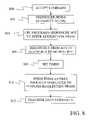
- FIG. 8is a flow diagram of a method of implementing a timeout error before a data transfer under one embodiment of the present invention.
- FIG. 9is a flow diagram of a method of implementing a timeout error after a data transfer under one embodiment of the present invention.
- FIG. 1is a flow chart of a method, according to one embodiment of the present invention, for generating errors in a Small Computer Systems Interface (SCSI) device to test the error handling capabilities of a host system.
- SCSISmall Computer Systems Interface
- the method of FIG. 1is described below with reference to the block diagram of FIG. 2 , which depicts a host system connected to a SCSI device.
- FIG. 2shows a host system connected to a SCSI data storage device.
- step 12an error injection mode page is received by data storage system 200 from a host computer system 295 .
- the error injection mode pageis transmitted from a host bus adapter 290 along SCSI parallel interface bus 262 to sequencer 256 in data storage system 200 .
- Sequencer 256uses buffer controller 254 to store the error mode page in command buffer 260 , which in one embodiment is a dynamic random access memory.
- Sequencer 256also sends an interrupt through an interface 259 to CPU 272 of firmware 270 , which acts as a co-processor with sequencer 256 .
- CPU 272transfers the error mode page to instruction store 276 in firmware 270 .
- FIG. 3depicts the layout of an error injection mode page 300 under one embodiment of the present invention.
- error injection mode page 300is a 24 byte data structure.
- Byte 0 of error injection mode page 300includes a Parameter Savable bit PS that indicates whether the page is savable on the data storage device and a page code field 302 that indicates that this is an error injection mode page.
- Byte 1indicates the length of the error injection mode page.
- Byte 2includes a reserved field 304 , a Repeat bit 306 and an Error Injection Enable bit 308 .
- Repeat bit 306indicates whether the error production sequence represented by the page should be repeated until a new error injection mode page is received.
- Error Injection Enable bit 308indicates whether the page stored in instruction store 276 should be executed. Error Injection Enable bit 308 is initially set to 1 to indicate that the error page should be executed. The bit is set to 0 after the error routine of the page has executed successfully, the drive power cycles, or the user changes the setting through a mode select.
- Byte 3is an Error Mode field that indicates the type of error to be produced. Examples of different possible error modes and how they are implemented under the present invention are discussed in more detail below.
- Byte 4contains a Command Op Code that indicates a target command that will trigger the production of the error when the command is received by sequencer 256 . Only commands that are consistent with the selected error mode set in the Error Mode field produce the error. If a command is included that is not allowed for an error mode, the device will reject the mode page as an illegal request.
- Bytes 5 , 6 and 7provide a sense key, a sense code, and a sense qualifier, respectively. When an Error Mode of zero is selected, the sense key, sense code and sense qualifier are returned as the error value.
- Bytes 8 - 11provide an Operations Until Event field that controls a number of operations a data storage system will count through, after receiving the simulated error mode communicated to it, before arming an error trigger.
- the operations until event numbermay be any number from zero to an arbitrarily high number.
- Bytes 12 and 13provide a Duration of Error field that applies only to certain error modes in this embodiment, and that is used in different ways in different error modes.
- the duration of error valueindicates the number of times the same error should be generated once the Operations Until Event counter has expired.
- the Duration of Error valueindicates the number of times an external recovery operation must be received to recover from an error. Once a number of recovery operations equal to the duration of error value have been received, the simulated error is resolved.
- the specific application of the duration of error value for each error modeis described further below, with reference to those specific error modes.
- Bytes 14 - 15provide a time-out field that contains a hang time that is used during error events in which the sequencer hangs in a particular state as described in further detail below.
- Bytes 16 - 23are reserved for later use.
- CPU 272Upon receiving the error injection mode page at step 12 , CPU 272 examines the page and uses the values in the fields to select a set of instructions for CPU 272 from instruction store 276 .
- CPU 272also sets the values of a collection of variables in a data store 274 that are used to execute the instructions. In particular, CPU 272 sets a command count, a trigger command, a duration error count, and a repeat count using the Operations Until Event field, the Command Op Code field, the Duration of Error field, and the repeat bit of the error injection mode page, respectively, at step 14 .
- CPU 272waits for sequencer 256 to receive a command at step 16 .
- sequencer 256stores the command in command buffer 260 using command buffer controller 254 .
- Sequencer 256also sends an interrupt to CPU 272 through an interface 259 to indicate that a new command has been received and stored in command buffer 260 .
- CPU 272evaluates the command count to determine if it is equal to zero. If the command count is greater than zero, CPU 272 instructs sequencer 256 to execute the command at step 20 . When the command finishes execution, CPU 272 reduces the command count by one at step 22 and returns to step 16 to wait for the next command.
- CPU 272determines if the command in command buffer 260 is the trigger command by accessing command buffer 260 through interface 259 and buffer controller 254 . If the command in buffer 260 is not the trigger command, the command is processed at step 20 and the process returns to step 16 to await the next command.
- CPU 272programs sequencer 256 at step 26 to execute a set of instructions to simulate the error listed in the error mode field of the error injection mode page. These instructions are stored in a sequencer instruction memory 258 through interface 259 . Examples of specific instructions are described below for the individual errors that can be set in the error mode field. Once the instructions are set in memory 258 , they are executed by sequencer 256 .
- CPU 272 and sequencer 256wait for an error recovery signal from host bus adapter 290 .
- error recovery signalsinclude bus resets, power cycles, Message Abort messages, Device Message Reset messages, and mode select commands.
- the appropriate error recovery signalis dependent on the particular error mode.
- CPU 272determines if the error mode and the duration of error field require more than one error recovery signal in order to recover from the error at step 30 . If more than one error recovery signal is required, the duration of error count is reduced at step 32 and the process returns to step 28 to wait for another recovery signal.
- CPU 272recovers from the error by resetting sequencer 256 so that it operates normally once again.
- CPU 272determines if the duration of error count is equal to zero at step 34 . If the duration of error count is not equal to zero, the duration of error count is reduced by one at step 36 and the process returns to step 16 to wait for the next command. Note that the command trigger continues to be active such that if the next command is the trigger command, an error simulation will be triggered at step 26 .
- the processexamines the repeat bit at step 38 . If the repeat bit is set, the command count and duration of error count are reset at step 40 and the process returns to step 16 to wait for a new command. Because the command count has been reset, the process will wait through the number of commands in the command count by cycling through steps 16 , 18 , 20 , and 22 before searching for the trigger command at step 24 .
- the repeat bit at step 38causes the error script set by the Operations Until Event field, the error mode and the Duration of Error field to be repeated until a new error injection mode page is received. If the repeat bit is not set at step 38 , the process ends at step 42 .
- FIG. 4depicts one illustrative embodiment of a method of a simulated error under the present invention.
- the method of FIG. 4simulates an error where sequencer 256 acts as if it is not responding to signals over the bus and is not currently using the bus. This is known as dropping off the bus.
- the method of FIG. 4begins at step 400 where sequencer 256 sends an interrupt to CPU 272 .
- any command received after the command count reaches zerowill act as a triggering command.
- CPU 272programs sequencer 256 to execute the pending command but to stop operations before entering the Status phase of communicating on the bus and to instead disconnect from the bus by entering the Bus Free phase.
- the sequencerexecutes the command and at step 404 goes Bus Free before entering the Status phase of the command.
- this error modewill persist until a selected number of bus reset commands has been communicated or the data storage system 200 has been put through a power cycle. Device message reset and Message Abort signals will not cause the drive to recover.
- the selected number of bus resetsis typically the duration of error number.
- CPU 272instructs sequencer 256 to go back on the Bus and to return to normal operations.
- the simulated error modeincludes causing the sequencer 256 to loop indefinitely in either a Data In phase or in a Data Out phase, until the data storage system is subjected to either a bus reset command or a power cycle. This is known as “hanging” on the bus during the Data In or Data Out phase.
- the error modeis triggered by a command that requires a Data In phase or a Data Out phase.
- sequencer 256sends an interrupt to CPU 272 at step 500 .
- CPU 272programs sequencer 256 at step 501 with a reduced transfer length for the data transfer, and arms sequencer 256 to loop indefinitely after transferring the data.
- sequencer 256sets the bus to indicate that it is in a Data In or Data Out state, depending on the command. Sequencer 256 then transfers the amount of data set in the reduced data length at step 504 .
- sequencer 256After the data has been transferred, sequencer 256 enters an indefinite loop at step 506 , during which it does not respond to signals on the bus. Note that because of the reduced transfer length, sequencer 256 has not transferred all of the data designated in the command. As a result, it appears to have “hung-up” in the middle of a data transfer. This error injection mode ends if the storage device is put through a power cycle or a bus reset is sent along the bus. Upon receiving the reset, CPU 272 reinitializes the sequencer 256 , which clears the reduced data length and the indefinite loop.
- FIG. 6provides a flow diagram of an additional error mode in which a particular error code designated in the error injection mode page is returned for a particular command set in the Command Op Code field of the mode page.
- the process of FIG. 6begins at step 600 where sequencer 256 sends an interrupt to CPU 272 to initiate the error process.
- CPU 272sets error code values to the values set in the sense key/code/qualifier fields in the mode page. Any of the sense key, sense code, or sense qualifier values that can be returned as an error may be designated in the sense key/code/qualifier field. This provides the ability to simulate more error types than was possible with the earlier Fiber Channel interface system described above.
- the commandis then examined at step 602 to determine if it is a write command.
- sequencer 256is instructed to begin executing the command at step 603 .
- CPU 272sets a timer 278 at step 604 .
- the timer periodis selected to allow sequencer 256 to transfer at least one block of data. Under one embodiment, a period of 100 ms is used.
- CPU 272posts a fake disc error to a disc error handler 280 , which is designed to receive disc errors from read-write channel 242 .
- disc error handler 280terminates the data transfer at step 608 and posts the error code provided in the sense key/code/qualifier fields of the mode page at step 610 .
- step 602If the command is not a write command at step 602 , the command in command buffer 260 is replaced by an illegal command by CPU 272 at step 614 .
- sequencer 256recognizes the command in the buffer as being illegal and sends the illegal command error code set in step 601 to host bus adapter 290 .
- the initial triggering commandis directed to a specific logical block address
- this errorwill only be re-triggered after recovery when the command is applied to the same logical block address.
- the initial triggering commandis a write command to logical block address A
- a write command to logical block address Bwill not re-trigger the error. Only another write command to logical block address A will re-trigger the error.
- FIG. 7provides a flow diagram of a method of injecting a data miscompare error, in which illegal data is returned during the execution of a read command.
- the method of FIG. 7starts at step 700 where CPU 272 programs sequencer 256 so that the sequencer will stop processing the read command just before it is ready to send the first block of data over the bus.
- the sequencerbegins execution of the read command by instructing the read channel 242 to read data from the designated logical block address.
- Read channel 242reads the data at step 704 using a recording and reading head 210 , which it positions over a physical position on a medium 204 based on the logical block address. This data read by head 210 is detected by read channel 242 , and is decoded into a storable format by a data formatter 252 before being stored in buffer 260 .
- sequencer 256halts the read operation before transferring data across the bus and sends an interrupt to CPU 272 .
- CPU 272modifies the first sector of data in buffer 260 so that the data includes a data miscompare error at step 708 .
- CPU 272then resets the code used by sequencer 256 at step 710 so that sequencer 256 can transfer the data normally at step 712 .
- FIG. 8provides a flow diagram for a method of injecting a time-out error before transferring data during a read or write command.
- the commandis accepted at step 800 and sequencer 256 sends an interrupt to CPU 272 at step 802 .
- CPU 272programs sequencer 256 to perform the command at step 804 but does not program sequencer 256 to perform the steps necessary to enter the reselection phase, which is used to establish a connection for transferring data. Because of this, sequencer 256 will not reconnect to the bus after it disconnects from the bus.
- sequencer 256disconnects from the bus. Such a disconnect step is common for read and write operations and frees the bus while the storage device is executing the command.
- a timer 278is set using the time-out value found in the error injection mode page. Because sequencer 256 has not been programmed to enter the reselection phase, it is prevented from connecting to the bus while the timer is counting down. When the timer expires at step 810 , the sequencer is programmed to perform the reselection phase and the sequencer transfers the data normally at step 812 .
- the method of FIG. 8is similar to the method of FIG. 4 except that in FIG. 8 , the sequencer disconnects from the bus before transferring data and only disconnects from the bus for a set period of time. In FIG. 4 , the sequencer disconnects from the bus until it receives a set number of resets.
- FIG. 9provides a flow diagram for a method of injecting a time-out error after transferring data during a read or write command.
- the commandis accepted and sequencer 256 sends an interrupt to CPU 272 at step 902 .
- CPU 272programs sequencer 256 at step 904 so that sequencer 256 will not enter the reselection phase after the transfer is complete and the bus has been released to make a status determination.
- sequencer 256disconnects from the bus in its normal fashion to execute the command.
- Sequencer 256prepares the data storage device for the transfer at step 908 and at step 910 enters the reselection phase to re-establish a connection to host bus adapter 290 . Once connected, the data transfer is performed at step 912 . Once the transfer is complete, sequencer 256 disconnects from the bus at step 914 as it would normally.
- a timeris set using the time-out value found in the error injection mode page. While the timer is counting down, sequencer 256 is prevented from entering the reselection phase and thus prevented from reconnecting to host bus adapter 290 . When the timer expires at step 918 , sequencer 256 is reprogrammed to enter the reselection phase to provide a connection to host bus adapter 290 . Once the connection is established at step 920 , sequencer 256 transfers a status to host bus adapter 290 .
- the data storage devicecan be reset through a power cycle, a single bus reset, a message abort or a device message reset.
- the present inventiontherefore includes unexpected and novel advantages as detailed herein and as can be further appreciated from the claims, figures, and description by those skilled in the art.
- particular embodimentsare described such as in reference to a disc drive, the present invention has various other embodiments with application to other methods and systems involving a great variety of contemplated embodiments, which lie within the metes and bounds of the claims.
- These embodimentsinclude optical, magnetic, magnetoresistive, giant magnetoresistive, and other types of disc drives, tape drives, volatile memory, arrays with a plurality of devices, and other specific examples.
- SCSISmall Computer System Interface
- the SCSI standardevolves over time and appears in different versions, and additional interfaces are contemplated that perform an equivalent function to the SCSI standard.
- the present inventionmay be used with other interfaces and interface standards, including those that have not yet risen to popularity but are within the contemplated scope of this invention.
- the error modes that produce data miscompares, timeouts, and that allow a sense key to be specified when requesting the error modecan be applied to any interface.
Landscapes
- Engineering & Computer Science (AREA)
- General Engineering & Computer Science (AREA)
- Theoretical Computer Science (AREA)
- Computer Hardware Design (AREA)
- Quality & Reliability (AREA)
- Physics & Mathematics (AREA)
- General Physics & Mathematics (AREA)
- Debugging And Monitoring (AREA)
Abstract
Description
Claims (20)
Priority Applications (1)
| Application Number | Priority Date | Filing Date | Title |
|---|---|---|---|
| US10/823,225US7406628B2 (en) | 2003-07-15 | 2004-04-13 | Simulated error injection system in target device for testing host system |
Applications Claiming Priority (2)
| Application Number | Priority Date | Filing Date | Title |
|---|---|---|---|
| US48780603P | 2003-07-15 | 2003-07-15 | |
| US10/823,225US7406628B2 (en) | 2003-07-15 | 2004-04-13 | Simulated error injection system in target device for testing host system |
Publications (2)
| Publication Number | Publication Date |
|---|---|
| US20050015679A1 US20050015679A1 (en) | 2005-01-20 |
| US7406628B2true US7406628B2 (en) | 2008-07-29 |
Family
ID=34068362
Family Applications (1)
| Application Number | Title | Priority Date | Filing Date |
|---|---|---|---|
| US10/823,225Expired - Fee RelatedUS7406628B2 (en) | 2003-07-15 | 2004-04-13 | Simulated error injection system in target device for testing host system |
Country Status (1)
| Country | Link |
|---|---|
| US (1) | US7406628B2 (en) |
Cited By (9)
| Publication number | Priority date | Publication date | Assignee | Title |
|---|---|---|---|---|
| US20070277070A1 (en)* | 2006-01-13 | 2007-11-29 | Infineon Technologies Ag | Apparatus and method for checking an error detection functionality of a data processor |
| US20090094389A1 (en)* | 2007-10-09 | 2009-04-09 | Seagate Technology, Llc | System and method of matching data rates |
| US20090313411A1 (en)* | 2008-06-12 | 2009-12-17 | Stenfort Ross J | Apparatus and methods crc error injection in a storage system |
| US8065410B1 (en) | 2004-03-31 | 2011-11-22 | Compuware Corporation | Methods and apparatus for collecting performance metrics from a web site |
| US20120110423A1 (en)* | 2010-11-02 | 2012-05-03 | Choung-Ki Song | Command control circuit, integrated circuit having the same, and command control method |
| US20130042152A1 (en)* | 2011-08-09 | 2013-02-14 | Lukás Fryc | Declarative testing using dependency injection |
| US8650447B1 (en) | 2011-07-14 | 2014-02-11 | Altera Corporation | Apparatus and methods for controlled error injection |
| US9626318B2 (en) | 2012-01-26 | 2017-04-18 | Avago Technologies General Ip (Singapore) Pte. Ltd. | Systems and methods for storage protocol compliance testing |
| US12339757B2 (en) | 2023-01-06 | 2025-06-24 | Dell Products L.P. | Method for error injection, electronic device, and computer program product |
Families Citing this family (4)
| Publication number | Priority date | Publication date | Assignee | Title |
|---|---|---|---|---|
| US7685273B1 (en)* | 2004-03-31 | 2010-03-23 | Compuware Corporation | Methods and apparatus for collecting and displaying performance metrics from a web site |
| US20080163005A1 (en)* | 2006-12-28 | 2008-07-03 | Sonksen Bradley S | Error injection in pci-express devices |
| US8296739B2 (en)* | 2008-03-31 | 2012-10-23 | International Business Machines Corporation | Testing soft error rate of an application program |
| JP5609986B2 (en)* | 2010-11-16 | 2014-10-22 | 富士通株式会社 | Information processing apparatus, transmission apparatus, and control method for information processing apparatus |
Citations (51)
| Publication number | Priority date | Publication date | Assignee | Title |
|---|---|---|---|---|
| JPS62259104A (en)* | 1986-05-06 | 1987-11-11 | Toshiba Corp | Sequencer |
| US4759019A (en)* | 1986-07-10 | 1988-07-19 | International Business Machines Corporation | Programmable fault injection tool |
| US4914657A (en)* | 1987-04-15 | 1990-04-03 | Allied-Signal Inc. | Operations controller for a fault tolerant multiple node processing system |
| US4999837A (en)* | 1989-03-20 | 1991-03-12 | International Business Machines Corporation | Programmable channel error injection |
| US5012465A (en)* | 1989-02-02 | 1991-04-30 | Alcatel Cit | Interconnection system for interconnecting connection units and a central switching facility |
| US5138617A (en)* | 1990-02-21 | 1992-08-11 | Honeywell Bull Inc. | Method for masking false bound faults in a central processing unit |
| US5210758A (en)* | 1988-06-13 | 1993-05-11 | Unisys Corporation | Means and method for detecting and correcting microinstruction errors |
| US5363379A (en)* | 1992-04-30 | 1994-11-08 | International Business Machines Corporation | FDDI network test adaptor error injection circuit |
| US5414713A (en)* | 1990-02-05 | 1995-05-09 | Synthesis Research, Inc. | Apparatus for testing digital electronic channels |
| US5428624A (en)* | 1993-10-12 | 1995-06-27 | Storage Technology Corporation | Fault injection using boundary scan |
| US5574855A (en)* | 1995-05-15 | 1996-11-12 | Emc Corporation | Method and apparatus for testing raid systems |
| US5671352A (en)* | 1995-07-07 | 1997-09-23 | Sun Microsystems, Inc. | Error injection to a behavioral model |
| US5796938A (en)* | 1996-12-11 | 1998-08-18 | International Business Machines Corporation | Diagnostic subsystem and method for SCSI Interface |
| US5872910A (en) | 1996-12-27 | 1999-02-16 | Unisys Corporation | Parity-error injection system for an instruction processor |
| US5938779A (en)* | 1997-02-27 | 1999-08-17 | Alcatel Alsthom Compagnie Generale D'electricite | Asic control and data retrieval method and apparatus having an internal collateral test interface function |
| US6134676A (en) | 1998-04-30 | 2000-10-17 | International Business Machines Corporation | Programmable hardware event monitoring method |
| US6182248B1 (en)* | 1998-04-07 | 2001-01-30 | International Business Machines Corporation | Method and tool for computer bus fault isolation and recovery design verification |
| US6304984B1 (en) | 1998-09-29 | 2001-10-16 | International Business Machines Corporation | Method and system for injecting errors to a device within a computer system |
| US6327676B1 (en)* | 1998-03-31 | 2001-12-04 | Emc Corporation | Test equipment |
| US6336088B1 (en)* | 1998-12-22 | 2002-01-01 | Unisys Corporation | Method and apparatus for synchronizing independently executing test lists for design verification |
| US20020083262A1 (en)* | 1999-04-05 | 2002-06-27 | Tomoya Fukuzumi | Memory device operable with a small-capacity buffer memory and having a flash memory |
| US20020095624A1 (en)* | 2000-12-04 | 2002-07-18 | International Business Machines Corporation | Method for testing a computer bus using a bridge chip having a freeze-on-error option |
| US6457147B1 (en)* | 1999-06-08 | 2002-09-24 | International Business Machines Corporation | Method and system for run-time logic verification of operations in digital systems in response to a plurality of parameters |
| US20020138510A1 (en)* | 2001-01-24 | 2002-09-26 | Sun Microsystems, Inc. | Method, system, and program for tracking quality assurance processes |
| US6484276B1 (en)* | 1999-10-25 | 2002-11-19 | Lucent Technologies Inc. | Method and apparatus for providing extensible object-oriented fault injection |
| US6484274B1 (en) | 1996-09-16 | 2002-11-19 | Advanced Micro Devices, Inc. | Method for identifying and correcting error in a central processing unit |
| US20030014580A1 (en)* | 1999-06-30 | 2003-01-16 | B. Arlen Young | A scsi phase status register for use in reducing instructions executed by an on-chip sequencer in asserting a scsi ackowledge signal and method |
| US6519718B1 (en)* | 2000-02-18 | 2003-02-11 | International Business Machines Corporation | Method and apparatus implementing error injection for PCI bridges |
| US6539503B1 (en) | 1999-11-23 | 2003-03-25 | Hewlett-Packard Company | Method and apparatus for testing error detection |
| US6546507B1 (en) | 1999-08-31 | 2003-04-08 | Sun Microsystems, Inc. | Method and apparatus for operational envelope testing of busses to identify halt limits |
| US6560720B1 (en)* | 1999-09-09 | 2003-05-06 | International Business Machines Corporation | Error injection apparatus and method |
| US6590929B1 (en)* | 1999-06-08 | 2003-07-08 | International Business Machines Corporation | Method and system for run-time logic verification of operations in digital systems |
| US6604211B1 (en) | 1999-08-31 | 2003-08-05 | Seagate Technology Llc | Tool for initiating and analyzing error recovery procedures in data storage devices |
| US6609221B1 (en) | 1999-08-31 | 2003-08-19 | Sun Microsystems, Inc. | Method and apparatus for inducing bus saturation during operational testing of busses using a pattern generator |
| US20030172321A1 (en)* | 2002-03-11 | 2003-09-11 | Wolin Dale Haddon | System and methods for fault path testing through automated error injection |
| US20030179712A1 (en)* | 1994-08-22 | 2003-09-25 | Yasusi Kobayashi | Connectionless communications system, its test method, and intra-station control system |
| US20030226062A1 (en)* | 2002-06-03 | 2003-12-04 | Gender Thomas K. | System and method for testing response to asynchronous system errors |
| US6701460B1 (en)* | 1999-10-21 | 2004-03-02 | Sun Microsystems, Inc. | Method and apparatus for testing a computer system through software fault injection |
| US6718413B1 (en)* | 1999-08-31 | 2004-04-06 | Adaptec, Inc. | Contention-based methods for generating reduced number of interrupts |
| US6751756B1 (en)* | 2000-12-01 | 2004-06-15 | Unisys Corporation | First level cache parity error inject |
| US20040199718A1 (en)* | 2003-03-10 | 2004-10-07 | Byers Larry L. | Method and system for embedded disk controllers |
| US6807581B1 (en)* | 2000-09-29 | 2004-10-19 | Alacritech, Inc. | Intelligent network storage interface system |
| US20040225932A1 (en)* | 2003-05-10 | 2004-11-11 | Hoda Sahir S. | Systems and methods for scripting data errors to facilitate verification of error detection or correction code functionality |
| US20040267516A1 (en)* | 2003-06-30 | 2004-12-30 | Jibbe Mahmoud K. | Method for controlling and emulating functional and logical behaviors of an array of storage devices for different protocols |
| US6886116B1 (en)* | 2001-07-26 | 2005-04-26 | Emc Corporation | Data storage system adapted to validate error detection logic used in such system |
| US6976189B1 (en)* | 2002-03-22 | 2005-12-13 | Network Appliance, Inc. | Persistent context-based behavior injection or testing of a computing system |
| US6981173B2 (en)* | 2001-09-28 | 2005-12-27 | Hewlett-Packard Development Company, L.P. | Redundant memory sequence and fault isolation |
| US7065677B1 (en)* | 2003-04-10 | 2006-06-20 | Microsoft Corporation | Method for testing operating system components |
| US7107490B2 (en)* | 2002-01-03 | 2006-09-12 | International Business Machines Corporation | IML-stream generated error insertion / FRU isolation |
| US7124205B2 (en)* | 1997-10-14 | 2006-10-17 | Alacritech, Inc. | Network interface device that fast-path processes solicited session layer read commands |
| US7343514B2 (en)* | 2002-08-28 | 2008-03-11 | Nec Corporation | Data copying system, relaying device, data transfer/reception system and program for copying of data in storage unit |
- 2004
- 2004-04-13USUS10/823,225patent/US7406628B2/ennot_activeExpired - Fee Related
Patent Citations (53)
| Publication number | Priority date | Publication date | Assignee | Title |
|---|---|---|---|---|
| JPS62259104A (en)* | 1986-05-06 | 1987-11-11 | Toshiba Corp | Sequencer |
| US4759019A (en)* | 1986-07-10 | 1988-07-19 | International Business Machines Corporation | Programmable fault injection tool |
| US4914657A (en)* | 1987-04-15 | 1990-04-03 | Allied-Signal Inc. | Operations controller for a fault tolerant multiple node processing system |
| US5210758A (en)* | 1988-06-13 | 1993-05-11 | Unisys Corporation | Means and method for detecting and correcting microinstruction errors |
| US5012465A (en)* | 1989-02-02 | 1991-04-30 | Alcatel Cit | Interconnection system for interconnecting connection units and a central switching facility |
| US4999837A (en)* | 1989-03-20 | 1991-03-12 | International Business Machines Corporation | Programmable channel error injection |
| US5414713A (en)* | 1990-02-05 | 1995-05-09 | Synthesis Research, Inc. | Apparatus for testing digital electronic channels |
| US5138617A (en)* | 1990-02-21 | 1992-08-11 | Honeywell Bull Inc. | Method for masking false bound faults in a central processing unit |
| US5363379A (en)* | 1992-04-30 | 1994-11-08 | International Business Machines Corporation | FDDI network test adaptor error injection circuit |
| US5428624A (en)* | 1993-10-12 | 1995-06-27 | Storage Technology Corporation | Fault injection using boundary scan |
| US20030179712A1 (en)* | 1994-08-22 | 2003-09-25 | Yasusi Kobayashi | Connectionless communications system, its test method, and intra-station control system |
| US5574855A (en)* | 1995-05-15 | 1996-11-12 | Emc Corporation | Method and apparatus for testing raid systems |
| US5671352A (en)* | 1995-07-07 | 1997-09-23 | Sun Microsystems, Inc. | Error injection to a behavioral model |
| US6484274B1 (en) | 1996-09-16 | 2002-11-19 | Advanced Micro Devices, Inc. | Method for identifying and correcting error in a central processing unit |
| US5796938A (en)* | 1996-12-11 | 1998-08-18 | International Business Machines Corporation | Diagnostic subsystem and method for SCSI Interface |
| US5872910A (en) | 1996-12-27 | 1999-02-16 | Unisys Corporation | Parity-error injection system for an instruction processor |
| US5938779A (en)* | 1997-02-27 | 1999-08-17 | Alcatel Alsthom Compagnie Generale D'electricite | Asic control and data retrieval method and apparatus having an internal collateral test interface function |
| US7124205B2 (en)* | 1997-10-14 | 2006-10-17 | Alacritech, Inc. | Network interface device that fast-path processes solicited session layer read commands |
| US6327676B1 (en)* | 1998-03-31 | 2001-12-04 | Emc Corporation | Test equipment |
| US6182248B1 (en)* | 1998-04-07 | 2001-01-30 | International Business Machines Corporation | Method and tool for computer bus fault isolation and recovery design verification |
| US6134676A (en) | 1998-04-30 | 2000-10-17 | International Business Machines Corporation | Programmable hardware event monitoring method |
| US6304984B1 (en) | 1998-09-29 | 2001-10-16 | International Business Machines Corporation | Method and system for injecting errors to a device within a computer system |
| US6336088B1 (en)* | 1998-12-22 | 2002-01-01 | Unisys Corporation | Method and apparatus for synchronizing independently executing test lists for design verification |
| US20020083262A1 (en)* | 1999-04-05 | 2002-06-27 | Tomoya Fukuzumi | Memory device operable with a small-capacity buffer memory and having a flash memory |
| US6457147B1 (en)* | 1999-06-08 | 2002-09-24 | International Business Machines Corporation | Method and system for run-time logic verification of operations in digital systems in response to a plurality of parameters |
| US6590929B1 (en)* | 1999-06-08 | 2003-07-08 | International Business Machines Corporation | Method and system for run-time logic verification of operations in digital systems |
| US20030014580A1 (en)* | 1999-06-30 | 2003-01-16 | B. Arlen Young | A scsi phase status register for use in reducing instructions executed by an on-chip sequencer in asserting a scsi ackowledge signal and method |
| US6535936B2 (en)* | 1999-06-30 | 2003-03-18 | Adaptec, Inc. | SCSI phase status register for use in reducing instructions executed by an on-chip sequencer in asserting a SCSI acknowledge signal and method |
| US6718413B1 (en)* | 1999-08-31 | 2004-04-06 | Adaptec, Inc. | Contention-based methods for generating reduced number of interrupts |
| US6609221B1 (en) | 1999-08-31 | 2003-08-19 | Sun Microsystems, Inc. | Method and apparatus for inducing bus saturation during operational testing of busses using a pattern generator |
| US6546507B1 (en) | 1999-08-31 | 2003-04-08 | Sun Microsystems, Inc. | Method and apparatus for operational envelope testing of busses to identify halt limits |
| US6604211B1 (en) | 1999-08-31 | 2003-08-05 | Seagate Technology Llc | Tool for initiating and analyzing error recovery procedures in data storage devices |
| US6560720B1 (en)* | 1999-09-09 | 2003-05-06 | International Business Machines Corporation | Error injection apparatus and method |
| US6701460B1 (en)* | 1999-10-21 | 2004-03-02 | Sun Microsystems, Inc. | Method and apparatus for testing a computer system through software fault injection |
| US6484276B1 (en)* | 1999-10-25 | 2002-11-19 | Lucent Technologies Inc. | Method and apparatus for providing extensible object-oriented fault injection |
| US6539503B1 (en) | 1999-11-23 | 2003-03-25 | Hewlett-Packard Company | Method and apparatus for testing error detection |
| US6519718B1 (en)* | 2000-02-18 | 2003-02-11 | International Business Machines Corporation | Method and apparatus implementing error injection for PCI bridges |
| US6807581B1 (en)* | 2000-09-29 | 2004-10-19 | Alacritech, Inc. | Intelligent network storage interface system |
| US6751756B1 (en)* | 2000-12-01 | 2004-06-15 | Unisys Corporation | First level cache parity error inject |
| US20020095624A1 (en)* | 2000-12-04 | 2002-07-18 | International Business Machines Corporation | Method for testing a computer bus using a bridge chip having a freeze-on-error option |
| US20020138510A1 (en)* | 2001-01-24 | 2002-09-26 | Sun Microsystems, Inc. | Method, system, and program for tracking quality assurance processes |
| US6886116B1 (en)* | 2001-07-26 | 2005-04-26 | Emc Corporation | Data storage system adapted to validate error detection logic used in such system |
| US6981173B2 (en)* | 2001-09-28 | 2005-12-27 | Hewlett-Packard Development Company, L.P. | Redundant memory sequence and fault isolation |
| US7107490B2 (en)* | 2002-01-03 | 2006-09-12 | International Business Machines Corporation | IML-stream generated error insertion / FRU isolation |
| US20030172321A1 (en)* | 2002-03-11 | 2003-09-11 | Wolin Dale Haddon | System and methods for fault path testing through automated error injection |
| US7020803B2 (en)* | 2002-03-11 | 2006-03-28 | Hewlett-Packard Development Company, Lp. | System and methods for fault path testing through automated error injection |
| US6976189B1 (en)* | 2002-03-22 | 2005-12-13 | Network Appliance, Inc. | Persistent context-based behavior injection or testing of a computing system |
| US20030226062A1 (en)* | 2002-06-03 | 2003-12-04 | Gender Thomas K. | System and method for testing response to asynchronous system errors |
| US7343514B2 (en)* | 2002-08-28 | 2008-03-11 | Nec Corporation | Data copying system, relaying device, data transfer/reception system and program for copying of data in storage unit |
| US20040199718A1 (en)* | 2003-03-10 | 2004-10-07 | Byers Larry L. | Method and system for embedded disk controllers |
| US7065677B1 (en)* | 2003-04-10 | 2006-06-20 | Microsoft Corporation | Method for testing operating system components |
| US20040225932A1 (en)* | 2003-05-10 | 2004-11-11 | Hoda Sahir S. | Systems and methods for scripting data errors to facilitate verification of error detection or correction code functionality |
| US20040267516A1 (en)* | 2003-06-30 | 2004-12-30 | Jibbe Mahmoud K. | Method for controlling and emulating functional and logical behaviors of an array of storage devices for different protocols |
Cited By (14)
| Publication number | Priority date | Publication date | Assignee | Title |
|---|---|---|---|---|
| US8065410B1 (en) | 2004-03-31 | 2011-11-22 | Compuware Corporation | Methods and apparatus for collecting performance metrics from a web site |
| US8918679B2 (en)* | 2006-01-13 | 2014-12-23 | Infineon Technologies Ag | Apparatus and method for checking an error detection functionality of a data processor |
| US20070277070A1 (en)* | 2006-01-13 | 2007-11-29 | Infineon Technologies Ag | Apparatus and method for checking an error detection functionality of a data processor |
| US20090094389A1 (en)* | 2007-10-09 | 2009-04-09 | Seagate Technology, Llc | System and method of matching data rates |
| US9201790B2 (en)* | 2007-10-09 | 2015-12-01 | Seagate Technology Llc | System and method of matching data rates |
| US20090313411A1 (en)* | 2008-06-12 | 2009-12-17 | Stenfort Ross J | Apparatus and methods crc error injection in a storage system |
| US8190983B2 (en)* | 2008-06-12 | 2012-05-29 | Lsi Corporation | Apparatus and methods for CRC error injection in a storage system |
| US20120110423A1 (en)* | 2010-11-02 | 2012-05-03 | Choung-Ki Song | Command control circuit, integrated circuit having the same, and command control method |
| US8566685B2 (en)* | 2010-11-02 | 2013-10-22 | Hynix Semiconductor Inc. | Command control circuit, integrated circuit having the same, and command control method |
| US8650447B1 (en) | 2011-07-14 | 2014-02-11 | Altera Corporation | Apparatus and methods for controlled error injection |
| US20130042152A1 (en)* | 2011-08-09 | 2013-02-14 | Lukás Fryc | Declarative testing using dependency injection |
| US9208064B2 (en)* | 2011-08-09 | 2015-12-08 | Red Hat, Inc. | Declarative testing using dependency injection |
| US9626318B2 (en) | 2012-01-26 | 2017-04-18 | Avago Technologies General Ip (Singapore) Pte. Ltd. | Systems and methods for storage protocol compliance testing |
| US12339757B2 (en) | 2023-01-06 | 2025-06-24 | Dell Products L.P. | Method for error injection, electronic device, and computer program product |
Also Published As
| Publication number | Publication date |
|---|---|
| US20050015679A1 (en) | 2005-01-20 |
Similar Documents
| Publication | Publication Date | Title |
|---|---|---|
| US7406628B2 (en) | Simulated error injection system in target device for testing host system | |
| US6983353B2 (en) | Method and apparatus for enhancing operations in disk array storage devices | |
| US4888691A (en) | Method for disk I/O transfer | |
| US6959399B2 (en) | Selective automated power cycling of faulty disk in intelligent disk array enclosure for error recovery | |
| EP2176772B1 (en) | Processing of data to monitor input/output operations | |
| EP0883843A4 (en) | METHOD AND APPARATUS FOR STARTING UP A COMPUTER WITH A DISK DRIVE FOR REMOVABLE MEDIA | |
| US7114112B2 (en) | Method, system, and program for simulating Input/Output (I/O) requests to test a system | |
| JP3777156B2 (en) | System and method for coordinating data storage device management operations in a data storage subsystem | |
| US20210065745A1 (en) | Multi-session concurrent testing for multi-actuator drive | |
| US5898859A (en) | Address shadow feature and methods of using the same | |
| US7366957B2 (en) | Method and apparatus for controlling SAS/fibre target behavior from a host | |
| US6760788B2 (en) | Domain validation process that is transparent to a device driver | |
| US8069364B2 (en) | Method to recover from logical path failures | |
| US20030023904A1 (en) | Pseudo I/O system and method | |
| JPH02186424A (en) | Disk control circuit | |
| TWI670721B (en) | Unusual power-off test method and device for storage device | |
| US7568121B2 (en) | Recovery from failure in data storage systems | |
| JP2807026B2 (en) | Execution reproduction method of parallel program | |
| CN107145420B (en) | OpenPower architecture-based automatic disk test method | |
| US12222856B2 (en) | Memory controller and method for controlling output of debug messages | |
| US7818627B2 (en) | Systems and methods for gathering debug information | |
| CN102163449B (en) | Method and system for testing burning tool, and embedded equipment | |
| TWI761915B (en) | Data storage device and parameter rewrite method thereof | |
| KR20240077035A (en) | Interworking Method between External Device and Storage Device | |
| CN120743649A (en) | Error injection method, system, program product and storage medium for protecting information |
Legal Events
| Date | Code | Title | Description |
|---|---|---|---|
| AS | Assignment | Owner name:SEAGATE TECHNOLOGY LLC, CALIFORNIA Free format text:ASSIGNMENT OF ASSIGNORS INTEREST;ASSIGNORS:EDGAR, BRIAN T.;LI, FENG;SCHMIDT, MARK A.;REEL/FRAME:015213/0817;SIGNING DATES FROM 20040331 TO 20040405 | |
| FEPP | Fee payment procedure | Free format text:PAYOR NUMBER ASSIGNED (ORIGINAL EVENT CODE: ASPN); ENTITY STATUS OF PATENT OWNER: LARGE ENTITY | |
| STCF | Information on status: patent grant | Free format text:PATENTED CASE | |
| AS | Assignment | Owner name:WELLS FARGO BANK, NATIONAL ASSOCIATION, AS COLLATERAL AGENT AND SECOND PRIORITY REPRESENTATIVE, CALIFORNIA Free format text:SECURITY AGREEMENT;ASSIGNORS:MAXTOR CORPORATION;SEAGATE TECHNOLOGY LLC;SEAGATE TECHNOLOGY INTERNATIONAL;REEL/FRAME:022757/0017 Effective date:20090507 Owner name:JPMORGAN CHASE BANK, N.A., AS ADMINISTRATIVE AGENT AND FIRST PRIORITY REPRESENTATIVE, NEW YORK Free format text:SECURITY AGREEMENT;ASSIGNORS:MAXTOR CORPORATION;SEAGATE TECHNOLOGY LLC;SEAGATE TECHNOLOGY INTERNATIONAL;REEL/FRAME:022757/0017 Effective date:20090507 Owner name:JPMORGAN CHASE BANK, N.A., AS ADMINISTRATIVE AGENT Free format text:SECURITY AGREEMENT;ASSIGNORS:MAXTOR CORPORATION;SEAGATE TECHNOLOGY LLC;SEAGATE TECHNOLOGY INTERNATIONAL;REEL/FRAME:022757/0017 Effective date:20090507 Owner name:WELLS FARGO BANK, NATIONAL ASSOCIATION, AS COLLATE Free format text:SECURITY AGREEMENT;ASSIGNORS:MAXTOR CORPORATION;SEAGATE TECHNOLOGY LLC;SEAGATE TECHNOLOGY INTERNATIONAL;REEL/FRAME:022757/0017 Effective date:20090507 | |
| AS | Assignment | Owner name:MAXTOR CORPORATION, CALIFORNIA Free format text:RELEASE;ASSIGNOR:JPMORGAN CHASE BANK, N.A., AS ADMINISTRATIVE AGENT;REEL/FRAME:025662/0001 Effective date:20110114 Owner name:SEAGATE TECHNOLOGY INTERNATIONAL, CALIFORNIA Free format text:RELEASE;ASSIGNOR:JPMORGAN CHASE BANK, N.A., AS ADMINISTRATIVE AGENT;REEL/FRAME:025662/0001 Effective date:20110114 Owner name:SEAGATE TECHNOLOGY LLC, CALIFORNIA Free format text:RELEASE;ASSIGNOR:JPMORGAN CHASE BANK, N.A., AS ADMINISTRATIVE AGENT;REEL/FRAME:025662/0001 Effective date:20110114 Owner name:SEAGATE TECHNOLOGY HDD HOLDINGS, CALIFORNIA Free format text:RELEASE;ASSIGNOR:JPMORGAN CHASE BANK, N.A., AS ADMINISTRATIVE AGENT;REEL/FRAME:025662/0001 Effective date:20110114 | |
| AS | Assignment | Owner name:THE BANK OF NOVA SCOTIA, AS ADMINISTRATIVE AGENT, CANADA Free format text:SECURITY AGREEMENT;ASSIGNOR:SEAGATE TECHNOLOGY LLC;REEL/FRAME:026010/0350 Effective date:20110118 Owner name:THE BANK OF NOVA SCOTIA, AS ADMINISTRATIVE AGENT, Free format text:SECURITY AGREEMENT;ASSIGNOR:SEAGATE TECHNOLOGY LLC;REEL/FRAME:026010/0350 Effective date:20110118 | |
| FPAY | Fee payment | Year of fee payment:4 | |
| AS | Assignment | Owner name:EVAULT INC. (F/K/A I365 INC.), CALIFORNIA Free format text:TERMINATION AND RELEASE OF SECURITY INTEREST IN PATENT RIGHTS;ASSIGNOR:WELLS FARGO BANK, NATIONAL ASSOCIATION, AS COLLATERAL AGENT AND SECOND PRIORITY REPRESENTATIVE;REEL/FRAME:030833/0001 Effective date:20130312 Owner name:SEAGATE TECHNOLOGY US HOLDINGS, INC., CALIFORNIA Free format text:TERMINATION AND RELEASE OF SECURITY INTEREST IN PATENT RIGHTS;ASSIGNOR:WELLS FARGO BANK, NATIONAL ASSOCIATION, AS COLLATERAL AGENT AND SECOND PRIORITY REPRESENTATIVE;REEL/FRAME:030833/0001 Effective date:20130312 Owner name:SEAGATE TECHNOLOGY INTERNATIONAL, CAYMAN ISLANDS Free format text:TERMINATION AND RELEASE OF SECURITY INTEREST IN PATENT RIGHTS;ASSIGNOR:WELLS FARGO BANK, NATIONAL ASSOCIATION, AS COLLATERAL AGENT AND SECOND PRIORITY REPRESENTATIVE;REEL/FRAME:030833/0001 Effective date:20130312 Owner name:SEAGATE TECHNOLOGY LLC, CALIFORNIA Free format text:TERMINATION AND RELEASE OF SECURITY INTEREST IN PATENT RIGHTS;ASSIGNOR:WELLS FARGO BANK, NATIONAL ASSOCIATION, AS COLLATERAL AGENT AND SECOND PRIORITY REPRESENTATIVE;REEL/FRAME:030833/0001 Effective date:20130312 | |
| FPAY | Fee payment | Year of fee payment:8 | |
| FEPP | Fee payment procedure | Free format text:MAINTENANCE FEE REMINDER MAILED (ORIGINAL EVENT CODE: REM.); ENTITY STATUS OF PATENT OWNER: LARGE ENTITY | |
| LAPS | Lapse for failure to pay maintenance fees | Free format text:PATENT EXPIRED FOR FAILURE TO PAY MAINTENANCE FEES (ORIGINAL EVENT CODE: EXP.); ENTITY STATUS OF PATENT OWNER: LARGE ENTITY | |
| STCH | Information on status: patent discontinuation | Free format text:PATENT EXPIRED DUE TO NONPAYMENT OF MAINTENANCE FEES UNDER 37 CFR 1.362 | |
| FP | Lapsed due to failure to pay maintenance fee | Effective date:20200729 | |
| AS | Assignment | Owner name:SEAGATE TECHNOLOGY PUBLIC LIMITED COMPANY, CALIFORNIA Free format text:RELEASE BY SECURED PARTY;ASSIGNOR:THE BANK OF NOVA SCOTIA;REEL/FRAME:072193/0001 Effective date:20250303 Owner name:SEAGATE TECHNOLOGY, CALIFORNIA Free format text:RELEASE BY SECURED PARTY;ASSIGNOR:THE BANK OF NOVA SCOTIA;REEL/FRAME:072193/0001 Effective date:20250303 Owner name:SEAGATE TECHNOLOGY HDD HOLDINGS, CALIFORNIA Free format text:RELEASE BY SECURED PARTY;ASSIGNOR:THE BANK OF NOVA SCOTIA;REEL/FRAME:072193/0001 Effective date:20250303 Owner name:I365 INC., CALIFORNIA Free format text:RELEASE BY SECURED PARTY;ASSIGNOR:THE BANK OF NOVA SCOTIA;REEL/FRAME:072193/0001 Effective date:20250303 Owner name:SEAGATE TECHNOLOGY LLC, CALIFORNIA Free format text:RELEASE BY SECURED PARTY;ASSIGNOR:THE BANK OF NOVA SCOTIA;REEL/FRAME:072193/0001 Effective date:20250303 Owner name:SEAGATE TECHNOLOGY INTERNATIONAL, CAYMAN ISLANDS Free format text:RELEASE BY SECURED PARTY;ASSIGNOR:THE BANK OF NOVA SCOTIA;REEL/FRAME:072193/0001 Effective date:20250303 Owner name:SEAGATE HDD CAYMAN, CAYMAN ISLANDS Free format text:RELEASE BY SECURED PARTY;ASSIGNOR:THE BANK OF NOVA SCOTIA;REEL/FRAME:072193/0001 Effective date:20250303 Owner name:SEAGATE TECHNOLOGY (US) HOLDINGS, INC., CALIFORNIA Free format text:RELEASE BY SECURED PARTY;ASSIGNOR:THE BANK OF NOVA SCOTIA;REEL/FRAME:072193/0001 Effective date:20250303 |