US7405530B2 - Method and apparatus for automatically establishing control values for a control device - Google Patents
Method and apparatus for automatically establishing control values for a control deviceDownload PDFInfo
- Publication number
- US7405530B2 US7405530B2US09/997,892US99789201AUS7405530B2US 7405530 B2US7405530 B2US 7405530B2US 99789201 AUS99789201 AUS 99789201AUS 7405530 B2US7405530 B2US 7405530B2
- Authority
- US
- United States
- Prior art keywords
- force control
- physical
- specific
- motor
- control value
- Prior art date
- Legal status (The legal status is an assumption and is not a legal conclusion. Google has not performed a legal analysis and makes no representation as to the accuracy of the status listed.)
- Expired - Lifetime, expires
Links
Images


Classifications
- G—PHYSICS
- G01—MEASURING; TESTING
- G01D—MEASURING NOT SPECIALLY ADAPTED FOR A SPECIFIC VARIABLE; ARRANGEMENTS FOR MEASURING TWO OR MORE VARIABLES NOT COVERED IN A SINGLE OTHER SUBCLASS; TARIFF METERING APPARATUS; MEASURING OR TESTING NOT OTHERWISE PROVIDED FOR
- G01D18/00—Testing or calibrating apparatus or arrangements provided for in groups G01D1/00 - G01D15/00
- G01D18/008—Testing or calibrating apparatus or arrangements provided for in groups G01D1/00 - G01D15/00 with calibration coefficients stored in memory
- E—FIXED CONSTRUCTIONS
- E05—LOCKS; KEYS; WINDOW OR DOOR FITTINGS; SAFES
- E05F—DEVICES FOR MOVING WINGS INTO OPEN OR CLOSED POSITION; CHECKS FOR WINGS; WING FITTINGS NOT OTHERWISE PROVIDED FOR, CONCERNED WITH THE FUNCTIONING OF THE WING
- E05F15/00—Power-operated mechanisms for wings
- E05F15/60—Power-operated mechanisms for wings using electrical actuators
- E05F15/603—Power-operated mechanisms for wings using electrical actuators using rotary electromotors
- E05F15/665—Power-operated mechanisms for wings using electrical actuators using rotary electromotors for vertically-sliding wings
- E05F15/668—Power-operated mechanisms for wings using electrical actuators using rotary electromotors for vertically-sliding wings for overhead wings
- E—FIXED CONSTRUCTIONS
- E05—LOCKS; KEYS; WINDOW OR DOOR FITTINGS; SAFES
- E05Y—INDEXING SCHEME ASSOCIATED WITH SUBCLASSES E05D AND E05F, RELATING TO CONSTRUCTION ELEMENTS, ELECTRIC CONTROL, POWER SUPPLY, POWER SIGNAL OR TRANSMISSION, USER INTERFACES, MOUNTING OR COUPLING, DETAILS, ACCESSORIES, AUXILIARY OPERATIONS NOT OTHERWISE PROVIDED FOR, APPLICATION THEREOF
- E05Y2400/00—Electronic control; Electrical power; Power supply; Power or signal transmission; User interfaces
- E05Y2400/10—Electronic control
- E05Y2400/30—Electronic control of motors
- E05Y2400/31—Force or torque control
- E05Y2400/315—Curve setting or adjusting
- E—FIXED CONSTRUCTIONS
- E05—LOCKS; KEYS; WINDOW OR DOOR FITTINGS; SAFES
- E05Y—INDEXING SCHEME ASSOCIATED WITH SUBCLASSES E05D AND E05F, RELATING TO CONSTRUCTION ELEMENTS, ELECTRIC CONTROL, POWER SUPPLY, POWER SIGNAL OR TRANSMISSION, USER INTERFACES, MOUNTING OR COUPLING, DETAILS, ACCESSORIES, AUXILIARY OPERATIONS NOT OTHERWISE PROVIDED FOR, APPLICATION THEREOF
- E05Y2400/00—Electronic control; Electrical power; Power supply; Power or signal transmission; User interfaces
- E05Y2400/10—Electronic control
- E05Y2400/52—Safety arrangements associated with the wing motor
- E05Y2400/53—Wing impact prevention or reduction
- E05Y2400/54—Obstruction or resistance detection
- E05Y2400/58—Sensitivity setting or adjustment
- E—FIXED CONSTRUCTIONS
- E05—LOCKS; KEYS; WINDOW OR DOOR FITTINGS; SAFES
- E05Y—INDEXING SCHEME ASSOCIATED WITH SUBCLASSES E05D AND E05F, RELATING TO CONSTRUCTION ELEMENTS, ELECTRIC CONTROL, POWER SUPPLY, POWER SIGNAL OR TRANSMISSION, USER INTERFACES, MOUNTING OR COUPLING, DETAILS, ACCESSORIES, AUXILIARY OPERATIONS NOT OTHERWISE PROVIDED FOR, APPLICATION THEREOF
- E05Y2800/00—Details, accessories and auxiliary operations not otherwise provided for
- E—FIXED CONSTRUCTIONS
- E05—LOCKS; KEYS; WINDOW OR DOOR FITTINGS; SAFES
- E05Y—INDEXING SCHEME ASSOCIATED WITH SUBCLASSES E05D AND E05F, RELATING TO CONSTRUCTION ELEMENTS, ELECTRIC CONTROL, POWER SUPPLY, POWER SIGNAL OR TRANSMISSION, USER INTERFACES, MOUNTING OR COUPLING, DETAILS, ACCESSORIES, AUXILIARY OPERATIONS NOT OTHERWISE PROVIDED FOR, APPLICATION THEREOF
- E05Y2900/00—Application of doors, windows, wings or fittings thereof
- E05Y2900/10—Application of doors, windows, wings or fittings thereof for buildings or parts thereof
- E05Y2900/106—Application of doors, windows, wings or fittings thereof for buildings or parts thereof for garages
Definitions
- This inventionrelates generally to control devices and more particularly to force controls as used with barrier controllers.
- Movable barrier controllersare known in the art. Such devices typically respond to an actuation signal by actuating a motor and causing a movable barrier to move (the movable barrier can be, for example, a garage door, a date, a shutter, and the like). These devices have become increasingly sophisticated. For example, such controllers are often able to sense resistance to barrier movement. Such information can be used in a variety of ways, including automatically reversing movement of the barrier upon detecting an obstacle in the moving barrier's path. Unfortunately, a universal setpoint does not exist that will work for all barrier controllers systems to facilitate, under all operating conditions, utterly reliable obstacle detection with zero false positives all the time. Consequently, many barrier controllers include a force control that can be adjusted for an individual controller in a particular setting to better ensure safe, reliable, and effective operation.
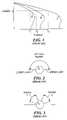
- FIG. 1Torque/speed curves are depicted for three motors A, B, and C. For a given speed S, motor A has a corresponding torque T 1 , motor B has a corresponding torque T 2 , and motor C has a corresponding torque T 3 . These torques can differ considerably from one another and should ordinarily be taken into account when selecting a force control settings that correspond to a particular speed.
- the force controltypically comprises a mechanical device having a corresponding mechanical setting range.
- a typical force controlcomprises a potentiometer having a user manipulative setting range that is bounded by a lower limit the and an upper limit.
- this setting rangeshould correspond to a useful setting range for a particular barrier controller system.
- Such correspondenceallows for greater useful resolution and granularity of control.
- For a given set of conditionsincluding a known motor and gear ratio
- operating conditionsoften change over the useful life of a given barrier controller system. By changing motors, as noted above, torque at a given speed can change considerably.
- a prior art force controlas designed to accommodate a variety of operating circumstances (including different motors and gear ratios) may have a relatively small useful range of settings for a first motor (as depicted by range 1 ) and a similar relatively small useful range of settings for a second motor (as depicted by range 2 ).
- this needshould be met in an economical and ergonomically sensitive manner. Further, minimized user responsibility to ensure such accommodation would be beneficial. Any such solution should also be relatively flexible and able to accommodate a relatively broad range of altered circumstances.
- FIG. 1comprises a prior art depiction of torque/speed curves for three motors
- FIG. 2comprises a generalized depiction of a prior art force control
- FIG. 3comprises a generalized depiction of a prior art force control
- FIG. 4comprises a block diagram depiction of a barrier controller system configured in accordance with an embodiment of the invention
- FIG. 5comprises a flow diagram configured in accordance with an embodiment of the invention
- FIG. 6comprises a detailed flow diagram configured in accordance with various embodiments of the invention.
- FIGS. 7 through 11comprise generalized depictions of force controls that illustrate various aspects and embodiments as configured in accordance with the invention.
- FIG. 12comprises a flow diagram configured in accordance with an embodiment of the invention.
- a deviceupon entering a learning mode, a device is automatically operated and at least one parameter that corresponds to operation of the device is automatically measured. That measured parameter is then used to establish a specific control value and that specific control value is then automatically assigned to a specific location within the mechanical setting range of a corresponding control device.
- a barrier controllercan operate its motor and measure at least one parameter that corresponds to operation of the motor. This measured parameter value is used to establish a specific force control value that is then assigned to a specific location within the user manipulative setting range for a force control.
- the setting range for a force controlcan be substantially optimized for a given set of operating conditions (including motor and gear ratio selection) as may occur over the installed life of the corresponding barrier controller system. This setting range optimization occurs substantially automatically.
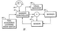
- a barrier controller system 40as configured in accordance with an embodiment of the invention includes a barrier controller 41 .
- Barrier controllersare well understood in the art and typically include a microprocessor or other computational platform that can be readily programmed in accordance with the teachings presented below.
- the system 40further includes a motor 42 that is controlled by the barrier controller 41 and that is appropriately coupled to a movable barrier 43 to effect movement of the barrier 43 between open and closed positions, all as well understood in the art.
- a sensor 47such as a Hall effect sensor, is positioned to sense a parameter that corresponds to operation of the motor 42 .
- the senor 47can be positioned to sense rotation of one or more magnets as are affixed to a gear, axle, or other surface that rotates as a function of the motor's 42 operation.
- the sensor 47can be positioned to sense direct movement of the barrier 43 .
- Other sensor types and locationscan be utilized as well so long as the sensor 47 can sense and respond to at least one parameter that corresponds to operation of the motor 42 .
- the system 40also includes a force control 44 such as a potentiometer that is operably coupled to the barrier controller 41 to provide a force sensitivity input that the barrier controller 41 utilizes, at a minimum, to establish obstacle detection and automatic reversing operation.
- a tool accessible learning mode switch 45is also provided to place the barrier controller 41 in a learning mode as described below.
- the learning mode switch 45can itself be a simple pushbutton that is manipulable by a user's finger, in which case access to the pushbutton should require a tool such as a screwdriver or other handheld implement.
- Other approachesare acceptable as well, including a switch that is recessed within a housing for the barrier controller 41 and that is screwdriver actuated by a screwdriver shaft that is inserted through a small hole in the housing as provided therefore.
- a visual indicator 46such as one or more light emitting diodes or other display platform is operably coupled to the barrier controller 41 to effect visual notifications in accordance with the teachings set forth below.
- the barrier controller 41is programmed such that upon entering 51 a learning mode the barrier controller 41 will operate 52 the motor 42 . The barrier controller 41 will then utilize the sensor 47 to measure 53 at least one parameter that corresponds to operation of the motor 42 to provide a parameter value. This parameter value is used to determine 54 a specific force control value, which value is then assigned 55 to a specific location of the user manipulable setting range for the force control 44 .
- a single assertion of this switch 45will initiate the learning mode 51 .
- the learning mode 51can only be initiated and/or maintained by asserting the switch 45 for either at least a predetermined period of time (such as, for example, five consecutive seconds) or for the entire duration of the learning cycle.
- a visual indicatorcan optionally be activated 61 to indicate to the user that the learning mode 51 has been initiated and/or is presently active. This visual indication can be provided by the visual indicator 46 described above.
- the learning mode 51will operate for a predetermined period of time.
- a timing functioncan be provided by a dedicated timer that provides timing information within and/or to the barrier controller 41 or by a software implemented timing function within the computational platform of the barrier controller 41 , all in accordance with well understood prior art technique.
- the learning mode 51can be rendered active for 30 seconds.
- the barrier controller 41then operates 52 the motor 42 .
- the motor 42is operated 52 in a substantially unloaded operating state. Operating 52 the motor 42 in this state will provide a reliable indication of the highest speed that the motor 42 is likely capable of.
- the motor 42is operated 52 in an ordinary loaded operating state. Operating 52 the motor 42 in this state will provide a reliable indication of the highest speed that the motor 42 is likely capable of under ordinary operating conditions. If desired, and as may be appropriate to a particular application, the motor 42 could be operated 52 under some other known predetermined operating condition, such as by operating the motor 42 while coupled to a specific known weight.
- the barrier controller 41measures 53 a parameter that corresponds to operation of the motor 42 .
- measurementcan be taken of a parameter that corresponds to speed of rotation of the motor's drive axle. This can be achieved, for example, by directly measuring speed of rotation of the drive axle, or by measuring speed of rotation of a rotating member that has a speed of rotation that varies with respect to speed of rotation of the drive axle of the motor 42 as a function of, for example, a gear ratio or pulley ratio.
- a parametercan be obtained by measuring a parameter that corresponds to speed of movement of the barrier 43 itself as the motor 42 operates.
- a sensor 47will provide electric pulses that corresponds to the sensed parameter.
- a gear platehas two magnets disposed on the plate and opposite from one another, two such electric pulses per revolution of the gear plate will be provided by the sensor 47 .
- two consecutive pulsescan be utilized to obtain a parameter value that corresponds to speed of rotation of the drive axle of the motor 42 .
- such pulsescan be counted over a predetermined period of time to obtain an average number of pulses per window of time. This average number can be utilized as the parameter value that corresponds to speed of rotation of the drive axle of the motor 42 .
- the parametercan be seen to correspond to the rotational output of the motor 42 , and hence the speed of the motor 42 .
- the barrier controller 41determines 54 a specific force control value while using the parameter value. For example, in one embodiment, the barrier controller 41 can assign the previously determined parameter value as the specific force control value. As an example of the latter, if the parameter value were “1600” as measured over a 32nd operating period and if this parameter value reflected sensor 47 output wherein one electrical pulses was provided per motor axle revolution, then the parameter value of “1600” could be used to assign a corresponding value as the force control value.
- the barrier controller 41can assign a modified version of the previously determined parameter value as the specific force control value.
- the parameter valuewere “3200” as measured over a one minute operating period and if this parameter value reflected sensor 47 output wherein two electrical pulses are provided per motor axle revolution, then the parameter value could be divided by two to obtain a specific force control value of “1600” (which value would correspond to 1600 rpm).
- additional control valuescan optionally be determined 64 as well.
- the previously determined force control valuecan be utilized to calculate a maximum force control value.
- a maximum force control valuecan be calculated by decreasing the previously determined force control value by a predetermined amount such as, for example, 10 percent.
- a previously determined force control value of “1600”would yield a calculated maximum force control value of “1440.”
- the previously determined force control valuecould be increased or decreased as appropriate by a specific amount or through consideration of other stored or measured parameters to calculate the maximum force control value.
- a lookup tablecould be utilized to correlate the previously determined force control value (or a modified version thereof) to a predetermined maximum force control value.
- the previously determined force control valuecould also be utilized to calculate or otherwise determine other control values as well.
- additional control valuescan simply be determined 64 by using previously stored control values, including a previously stored maximum force control value, either alone or in conjunction with the previously determined force control value.
- the initially determined control valueis assigned to one of the limits of the force control 44 and most typically is assigned to the lower limit of the setting range. For example, with reference to FIG. 7 a previously determined force control value of “1600” can be assigned to the lower limit 71 of the force control 44 . A maximum force control value as optionally previously determined 64 would be assigned to the upper limit 72 for the force control 44 . In the example depicted, the maximum force control value was calculated by decreasing the lower limit amount by 10 percent, yielding “1440” as the maximum force control value.
- remaining valuescan be assigned (or later interpolated) in a linear distribution between the lower limit 71 and the upper limit 72 .
- the intermediate valuescan be assigned in a nonlinear distribution instead of a linear distribution.
- the midway value “1520”can be assigned to a non-midway physical location 91 within the setting range of the force control 44 .
- this midway valuehas been assigned to a physical location 91 that is closer to the upper limit 72 than to the lower limit 71 .
- Such a positioningwould likely increase the granularity and resolution of sensitivity when selecting a control value between the lower limit 71 and the non-midway physical location 91 of the midway value while simultaneously reducing granularity and resolution of sensitivity when selecting a control value positioned more proximal to the upper limit 72 .
- FIG. 10depicts a force control 44 having a setting range where control values in a first portion 101 of the setting range are distributed in a linear fashion and where control values in a second portion 102 of the setting range are distributed in a nonlinear fashion.
- FIG. 11depicts a force control 44 having a setting range where control values in two portions 111 and 113 of the setting range are distributed in a linear manner and where control values in another portion 112 of the setting range are distributed in a nonlinear fashion.
- Implementation decisions regarding use of linear, nonlinear, or linear/nonlinear distribution patternscan be made apriori or dynamically at the time of assigning 55 such values to the setting range as appropriate to the application and/or flexibility required.
- the biasing voltage for that potentiometercan be varied to reflect the assigned control values. For example, if the presently applied bias voltage is 4 volts and if the barrier control or 41 is programmed to interpret 5 volts as 1440 and if the value to be assigned to the upper limit 72 is 1440, then altering the bias voltage from 4 volts to 5 volts will result in effectively assigning the control value “1440” to the upper limit 72 of the force control 44 .
- the bias voltagecan remain constant such that the force control 44 provides effectively never changing electric signals for each physical location within the setting range. In this case, the barrier controller 41 is itself modified to map (or calculate) those electric signals to the appropriate control value as assigned 55 during the learn mode 51 .
- the barrier controller 41can determine 121 whether the learn mode has been used. When eventually this determination 121 determines that the learning mode 51 has been processed and concluded, the barrier controller 41 can enable 122 other barrier control functionality to thereby facilitate normal use of the system 40 .
- the control values as determined 54 and assigned 55 during the learn mode 51are thereafter used 123 to correlate a particular user manipulated setting to a particular operational force control value as described above.
- the operating conditions for any given barrier controllercan be significantly altered over time. This includes the changing of motors and gear ratios. Notwithstanding such changes, upon initiation of the learn mode 51 , the barrier controller 41 can automatically ascertain one or more values to be assigned to the setting range of the force control 44 for that barrier controller. In particular, control values for the entire setting range can be selected to ensure that the setting range largely or wholly contains control values that are relevant and appropriate for the new operating conditions. This greatly enhances the ease of and likelihood that the operation of the barrier controller 41 will be appropriately adjusted to ensure both safe and appropriate performance.
Landscapes
- Physics & Mathematics (AREA)
- General Physics & Mathematics (AREA)
- Control Of Electric Motors In General (AREA)
- Control Of Position Or Direction (AREA)
- Feedback Control In General (AREA)
- Power-Operated Mechanisms For Wings (AREA)
Abstract
Description
Claims (42)
Priority Applications (8)
| Application Number | Priority Date | Filing Date | Title |
|---|---|---|---|
| US09/997,892US7405530B2 (en) | 2001-11-30 | 2001-11-30 | Method and apparatus for automatically establishing control values for a control device |
| CA002412263ACA2412263A1 (en) | 2001-11-30 | 2002-11-21 | Method and apparatus for automatically establishing control values for a control device |
| GB0227690AGB2384575B (en) | 2001-11-30 | 2002-11-27 | Method and apparatus for automatically establishing control values for a control device |
| AU2002306204AAU2002306204B2 (en) | 2001-11-30 | 2002-11-27 | Method and Apparatus for Automatically Establishing Control Values for a Control Device |
| NZ522846ANZ522846A (en) | 2001-11-30 | 2002-11-28 | Automatically establishing control values for potentiometer for barrier operation e.g. a garage door by initiating learning mode |
| DE10255891ADE10255891A1 (en) | 2001-11-30 | 2002-11-29 | Method and arrangement for automatically setting control values for a control device |
| FR0215027AFR2836299A1 (en) | 2001-11-30 | 2002-11-29 | DEVICE FOR CONTROLLING A BARRIER AND METHOD FOR USE THEREWITH |
| MXPA02011824AMXPA02011824A (en) | 2001-11-30 | 2002-11-29 | Method and apparatus for automatically establishing control values for a control device. |
Applications Claiming Priority (1)
| Application Number | Priority Date | Filing Date | Title |
|---|---|---|---|
| US09/997,892US7405530B2 (en) | 2001-11-30 | 2001-11-30 | Method and apparatus for automatically establishing control values for a control device |
Publications (2)
| Publication Number | Publication Date |
|---|---|
| US20030102837A1 US20030102837A1 (en) | 2003-06-05 |
| US7405530B2true US7405530B2 (en) | 2008-07-29 |
Family
ID=25544522
Family Applications (1)
| Application Number | Title | Priority Date | Filing Date |
|---|---|---|---|
| US09/997,892Expired - LifetimeUS7405530B2 (en) | 2001-11-30 | 2001-11-30 | Method and apparatus for automatically establishing control values for a control device |
Country Status (8)
| Country | Link |
|---|---|
| US (1) | US7405530B2 (en) |
| AU (1) | AU2002306204B2 (en) |
| CA (1) | CA2412263A1 (en) |
| DE (1) | DE10255891A1 (en) |
| FR (1) | FR2836299A1 (en) |
| GB (1) | GB2384575B (en) |
| MX (1) | MXPA02011824A (en) |
| NZ (1) | NZ522846A (en) |
Cited By (21)
| Publication number | Priority date | Publication date | Assignee | Title |
|---|---|---|---|---|
| US20050237018A1 (en)* | 2002-04-25 | 2005-10-27 | Aisin Seiki Kabushiki Kaisha | Operating mechanism of open/close body |
| US20060244271A1 (en)* | 2005-04-13 | 2006-11-02 | Dynatool Industries Inc. | Door operator assembly |
| US20090265992A1 (en)* | 2005-04-13 | 2009-10-29 | Brian Hass | Door Operator for Controlling a Door and Method of Same |
| US20110231023A1 (en)* | 2007-04-24 | 2011-09-22 | Yale Security Inc. | Door closer assembly |
| US20130082632A1 (en)* | 2011-09-30 | 2013-04-04 | Takuya Kusakawa | Electric power tool |
| US8415902B2 (en) | 2010-04-16 | 2013-04-09 | Yale Security Inc. | Door closer with calibration mode |
| US8527101B2 (en) | 2010-04-16 | 2013-09-03 | Yale Security Inc. | Door closer assembly |
| US8547046B2 (en) | 2010-04-16 | 2013-10-01 | Yale Security Inc. | Door closer with self-powered control unit |
| US8564235B2 (en) | 2010-04-16 | 2013-10-22 | Yale Security Inc. | Self-adjusting door closer |
| US8773237B2 (en) | 2010-04-16 | 2014-07-08 | Yale Security Inc. | Door closer with teach mode |
| US8779713B2 (en) | 2010-04-16 | 2014-07-15 | Yale Security Inc. | Door closer with dynamically adjustable latch region parameters |
| US9051768B2 (en) | 2011-05-24 | 2015-06-09 | Overhead Door Corporation | Force profiling barrier operator systems |
| US9080363B2 (en) | 2012-03-13 | 2015-07-14 | Ford Global Technologies, Llc | Vehicle door swing governor |
| US9461462B2 (en)* | 2014-06-24 | 2016-10-04 | Omron Automotive Electronics Co., Ltd. | Open-close body control apparatus |
| US9879465B2 (en)* | 2015-07-29 | 2018-01-30 | Ford Global Technologies, Llc | Programmable door power assist |
| US9995076B1 (en) | 2001-07-13 | 2018-06-12 | Steven M. Hoffberg | Intelligent door restraint |
| US10392849B2 (en) | 2017-01-18 | 2019-08-27 | Ford Global Technologies, Llc | Assembly and method to slow down and gently close door |
| US20200007054A1 (en)* | 2018-04-25 | 2020-01-02 | Schlage Lock Company Llc | Dynamic energy harvesting and variable harvesting force system |
| US10968676B2 (en) | 2018-04-24 | 2021-04-06 | Gmi Holdings, Inc. | Movable barrier apparatus and methods for responding to barrier travel obstructions and abnormalities |
| US11261648B2 (en) | 2019-12-20 | 2022-03-01 | The Chamberlain Group Llc | Movable barrier disengagement detection |
| US11746584B2 (en) | 2019-04-24 | 2023-09-05 | Gmi Holdings, Inc. | Remote monitoring and control of moveable barrier in jackshaft door operator system |
Families Citing this family (2)
| Publication number | Priority date | Publication date | Assignee | Title |
|---|---|---|---|---|
| US6667591B2 (en) | 2001-10-18 | 2003-12-23 | Wayne-Dalton Corp. | Method and device for increasing the allowed motor power of a motorized garage door operator |
| DE102006062333B4 (en)* | 2006-12-22 | 2016-05-12 | Geze Gmbh | Door or window drive |
Citations (19)
| Publication number | Priority date | Publication date | Assignee | Title |
|---|---|---|---|---|
| US4394607A (en) | 1981-05-08 | 1983-07-19 | Stanley Automatic Openers | Control systems for gates and the like including a motor overload monitoring circuit |
| US4625291A (en) | 1982-01-11 | 1986-11-25 | Hormann Kg | Process for monitoring a driven, movable door or the like |
| US4638433A (en) | 1984-05-30 | 1987-01-20 | Chamberlain Manufacturing Corporation | Microprocessor controlled garage door operator |
| US4673848A (en)* | 1984-12-29 | 1987-06-16 | Yoshida Kogyo K. K. | Control system for an automatic door |
| US4831509A (en) | 1986-04-16 | 1989-05-16 | Byrne & Davidson Doors (N.S.W.)Pty. Limited | Door operation control apparatus |
| US4855653A (en) | 1988-03-03 | 1989-08-08 | Stanley Automatic Openers | Obstruction detection in automatic portal control apparatus employing induction motor power factor |
| US5278480A (en)* | 1992-10-26 | 1994-01-11 | Stanley Home Automation | Door opener control with adaptive limits and method therefor |
| US5453736A (en)* | 1993-05-18 | 1995-09-26 | Besam Ab | Door operating system with programmed control unit |
| US5682090A (en)* | 1994-09-29 | 1997-10-28 | Ohi Seisakusho Co., Ltd. | Control device for power closure |
| US5982124A (en)* | 1995-08-30 | 1999-11-09 | Trw Inc. | Method and apparatus for adaptive control of a vehicle power window |
| US5986421A (en)* | 1997-08-14 | 1999-11-16 | Koito Manufacturing Co., Ltd. | Safety device for power window |
| US5994858A (en)* | 1997-09-01 | 1999-11-30 | Alps Electric Co., Ltd. | Method and apparatus for detecting obstruction to powered window movement |
| US6081203A (en)* | 1995-05-17 | 2000-06-27 | Chamberlain Group, Inc. | Code learning system for a movable barrier operator |
| US6097166A (en)* | 1995-06-06 | 2000-08-01 | The Chamberlain Group, Inc. | Movable barrier having force and position learning capability |
| US6133703A (en) | 1998-03-12 | 2000-10-17 | The Chamberlain Group, Inc. | Bi-directional pass-point system for controlling the operation of movable barriers |
| US6150784A (en)* | 1997-08-22 | 2000-11-21 | Alps Electric Co., Ltd. | Method of detecting foreign matter caught by window in power window device |
| US6172475B1 (en)* | 1998-09-28 | 2001-01-09 | The Chamberlain Group, Inc. | Movable barrier operator |
| US20010029437A1 (en) | 2000-02-28 | 2001-10-11 | Schneider Electric Industries Sa | Detector for monitoring rotation |
| US6426604B1 (en)* | 1999-05-21 | 2002-07-30 | Jidosha Denki Kogyo Kabushiki Kaisha | Power window controlling device |
Family Cites Families (2)
| Publication number | Priority date | Publication date | Assignee | Title |
|---|---|---|---|---|
| US6220096B1 (en)* | 1997-03-20 | 2001-04-24 | Interscience, Inc. | Differential wideband vibration |
| AU3143800A (en)* | 1999-01-18 | 2000-08-01 | Hormann Kg Antriebstechnik | Method and control mechanism for controlling a drive device for a closing deviceof a building or an enclosed area |
- 2001
- 2001-11-30USUS09/997,892patent/US7405530B2/ennot_activeExpired - Lifetime
- 2002
- 2002-11-21CACA002412263Apatent/CA2412263A1/ennot_activeAbandoned
- 2002-11-27AUAU2002306204Apatent/AU2002306204B2/ennot_activeCeased
- 2002-11-27GBGB0227690Apatent/GB2384575B/ennot_activeExpired - Fee Related
- 2002-11-28NZNZ522846Apatent/NZ522846A/ennot_activeApplication Discontinuation
- 2002-11-29DEDE10255891Apatent/DE10255891A1/ennot_activeWithdrawn
- 2002-11-29MXMXPA02011824Apatent/MXPA02011824A/ennot_activeApplication Discontinuation
- 2002-11-29FRFR0215027Apatent/FR2836299A1/ennot_activeWithdrawn
Patent Citations (27)
| Publication number | Priority date | Publication date | Assignee | Title |
|---|---|---|---|---|
| US4394607A (en) | 1981-05-08 | 1983-07-19 | Stanley Automatic Openers | Control systems for gates and the like including a motor overload monitoring circuit |
| US4625291A (en) | 1982-01-11 | 1986-11-25 | Hormann Kg | Process for monitoring a driven, movable door or the like |
| US4638433A (en) | 1984-05-30 | 1987-01-20 | Chamberlain Manufacturing Corporation | Microprocessor controlled garage door operator |
| US4673848A (en)* | 1984-12-29 | 1987-06-16 | Yoshida Kogyo K. K. | Control system for an automatic door |
| US4831509A (en) | 1986-04-16 | 1989-05-16 | Byrne & Davidson Doors (N.S.W.)Pty. Limited | Door operation control apparatus |
| US4855653A (en) | 1988-03-03 | 1989-08-08 | Stanley Automatic Openers | Obstruction detection in automatic portal control apparatus employing induction motor power factor |
| US5278480A (en)* | 1992-10-26 | 1994-01-11 | Stanley Home Automation | Door opener control with adaptive limits and method therefor |
| US5453736A (en)* | 1993-05-18 | 1995-09-26 | Besam Ab | Door operating system with programmed control unit |
| US5682090A (en)* | 1994-09-29 | 1997-10-28 | Ohi Seisakusho Co., Ltd. | Control device for power closure |
| US6081203A (en)* | 1995-05-17 | 2000-06-27 | Chamberlain Group, Inc. | Code learning system for a movable barrier operator |
| US6340872B1 (en)* | 1995-06-06 | 2002-01-22 | The Chamberlain Group, Inc. | Movable barrier operator having force and position learning capability |
| US6097166A (en)* | 1995-06-06 | 2000-08-01 | The Chamberlain Group, Inc. | Movable barrier having force and position learning capability |
| US6107765A (en)* | 1995-06-06 | 2000-08-22 | The Chamberlain Group, Inc. | Movable barrier operator having force and position learning capability |
| US6111374A (en)* | 1995-06-06 | 2000-08-29 | The Chamberlain Group, Inc. | Movable barrier operator having force and position learning capability |
| US6806665B2 (en)* | 1995-06-06 | 2004-10-19 | The Chamberlain Group, Inc. | Movable barrier operator having force and position learning capability |
| US6528961B1 (en)* | 1995-06-06 | 2003-03-04 | The Chamberlain Group, Inc. | Movable barrier operator having force and position learning capability |
| US6310451B1 (en)* | 1995-06-06 | 2001-10-30 | The Chamberlain Group, Inc. | Movable barrier operator having force and position learning capability |
| US5982124A (en)* | 1995-08-30 | 1999-11-09 | Trw Inc. | Method and apparatus for adaptive control of a vehicle power window |
| US5986421A (en)* | 1997-08-14 | 1999-11-16 | Koito Manufacturing Co., Ltd. | Safety device for power window |
| US6150784A (en)* | 1997-08-22 | 2000-11-21 | Alps Electric Co., Ltd. | Method of detecting foreign matter caught by window in power window device |
| US5994858A (en)* | 1997-09-01 | 1999-11-30 | Alps Electric Co., Ltd. | Method and apparatus for detecting obstruction to powered window movement |
| US6400112B1 (en) | 1998-03-12 | 2002-06-04 | The Chamberlain Group, Inc. | Bi-directional pass-point system for controlling the operation of movable barriers |
| US6133703A (en) | 1998-03-12 | 2000-10-17 | The Chamberlain Group, Inc. | Bi-directional pass-point system for controlling the operation of movable barriers |
| US6172475B1 (en)* | 1998-09-28 | 2001-01-09 | The Chamberlain Group, Inc. | Movable barrier operator |
| US6426604B1 (en)* | 1999-05-21 | 2002-07-30 | Jidosha Denki Kogyo Kabushiki Kaisha | Power window controlling device |
| US20010029437A1 (en) | 2000-02-28 | 2001-10-11 | Schneider Electric Industries Sa | Detector for monitoring rotation |
| US6799140B2 (en)* | 2000-02-28 | 2004-09-28 | Schneider Electric Industries Sa | Detector for monitoring rotation |
Non-Patent Citations (1)
| Title |
|---|
| U.K. Search Report for GB patent application GB 0227690.5 completed on May 22, 2003. |
Cited By (33)
| Publication number | Priority date | Publication date | Assignee | Title |
|---|---|---|---|---|
| US9995076B1 (en) | 2001-07-13 | 2018-06-12 | Steven M. Hoffberg | Intelligent door restraint |
| US11187022B1 (en) | 2001-07-13 | 2021-11-30 | Steven M. Hoffberg | Intelligent door restraint |
| US20050237018A1 (en)* | 2002-04-25 | 2005-10-27 | Aisin Seiki Kabushiki Kaisha | Operating mechanism of open/close body |
| US7637057B2 (en)* | 2002-04-25 | 2009-12-29 | Aisin Seiki Kabushiki Kaisha | Operating mechanism for an open/close object |
| US20060244271A1 (en)* | 2005-04-13 | 2006-11-02 | Dynatool Industries Inc. | Door operator assembly |
| US20090265992A1 (en)* | 2005-04-13 | 2009-10-29 | Brian Hass | Door Operator for Controlling a Door and Method of Same |
| US8169169B2 (en) | 2005-04-13 | 2012-05-01 | Brian Hass | Door operator for controlling a door and method of same |
| US10968677B2 (en) | 2005-04-13 | 2021-04-06 | ASSA ABLOY Accessories and Door Controls Group, Inc. | Door operator assembly |
| US10077591B2 (en)* | 2005-04-13 | 2018-09-18 | ASSA ABLOY Accessories and Door Controls Group, Inc. | Door operator assembly |
| US20110231023A1 (en)* | 2007-04-24 | 2011-09-22 | Yale Security Inc. | Door closer assembly |
| US9399884B2 (en) | 2007-04-24 | 2016-07-26 | Yale Security Inc. | Door closer assembly |
| US8600567B2 (en) | 2007-04-24 | 2013-12-03 | Yale Security Inc. | Door closer assembly |
| US8564235B2 (en) | 2010-04-16 | 2013-10-22 | Yale Security Inc. | Self-adjusting door closer |
| US8779713B2 (en) | 2010-04-16 | 2014-07-15 | Yale Security Inc. | Door closer with dynamically adjustable latch region parameters |
| US8773237B2 (en) | 2010-04-16 | 2014-07-08 | Yale Security Inc. | Door closer with teach mode |
| US8547046B2 (en) | 2010-04-16 | 2013-10-01 | Yale Security Inc. | Door closer with self-powered control unit |
| US8527101B2 (en) | 2010-04-16 | 2013-09-03 | Yale Security Inc. | Door closer assembly |
| US9523230B2 (en) | 2010-04-16 | 2016-12-20 | Yale Security Inc. | Door closer assembly |
| US8415902B2 (en) | 2010-04-16 | 2013-04-09 | Yale Security Inc. | Door closer with calibration mode |
| US9051768B2 (en) | 2011-05-24 | 2015-06-09 | Overhead Door Corporation | Force profiling barrier operator systems |
| US9512660B2 (en) | 2011-05-24 | 2016-12-06 | Overhead Door Corporation | Force profiling barrier operator systems |
| US8796976B2 (en)* | 2011-09-30 | 2014-08-05 | Makita Corporation | Electric power tool |
| US20130082632A1 (en)* | 2011-09-30 | 2013-04-04 | Takuya Kusakawa | Electric power tool |
| US9080363B2 (en) | 2012-03-13 | 2015-07-14 | Ford Global Technologies, Llc | Vehicle door swing governor |
| US9461462B2 (en)* | 2014-06-24 | 2016-10-04 | Omron Automotive Electronics Co., Ltd. | Open-close body control apparatus |
| US9879465B2 (en)* | 2015-07-29 | 2018-01-30 | Ford Global Technologies, Llc | Programmable door power assist |
| US10392849B2 (en) | 2017-01-18 | 2019-08-27 | Ford Global Technologies, Llc | Assembly and method to slow down and gently close door |
| US10968676B2 (en) | 2018-04-24 | 2021-04-06 | Gmi Holdings, Inc. | Movable barrier apparatus and methods for responding to barrier travel obstructions and abnormalities |
| US11834887B2 (en) | 2018-04-24 | 2023-12-05 | Gmi Holdings, Inc. | Movable barrier apparatus and methods for responding to barrier travel obstructions and abnormalities |
| US20200007054A1 (en)* | 2018-04-25 | 2020-01-02 | Schlage Lock Company Llc | Dynamic energy harvesting and variable harvesting force system |
| US10790766B2 (en)* | 2018-04-25 | 2020-09-29 | Schlage Lock Company Llc | Dynamic energy harvesting and variable harvesting force system |
| US11746584B2 (en) | 2019-04-24 | 2023-09-05 | Gmi Holdings, Inc. | Remote monitoring and control of moveable barrier in jackshaft door operator system |
| US11261648B2 (en) | 2019-12-20 | 2022-03-01 | The Chamberlain Group Llc | Movable barrier disengagement detection |
Also Published As
| Publication number | Publication date |
|---|---|
| NZ522846A (en) | 2004-06-25 |
| CA2412263A1 (en) | 2003-05-30 |
| AU2002306204B2 (en) | 2008-03-13 |
| GB2384575B (en) | 2005-09-07 |
| FR2836299A1 (en) | 2003-08-22 |
| GB2384575A (en) | 2003-07-30 |
| MXPA02011824A (en) | 2004-09-03 |
| DE10255891A1 (en) | 2003-06-18 |
| GB0227690D0 (en) | 2003-01-08 |
| US20030102837A1 (en) | 2003-06-05 |
Similar Documents
| Publication | Publication Date | Title |
|---|---|---|
| US7405530B2 (en) | Method and apparatus for automatically establishing control values for a control device | |
| US5770934A (en) | Method for the closed-loop control of an automatic door which is propelled by a drive motor | |
| US20210078151A1 (en) | Multi-speed power tool with electronic clutch | |
| CA2452919C (en) | Improved method, system and apparatus for opening doors | |
| US5278480A (en) | Door opener control with adaptive limits and method therefor | |
| US5780988A (en) | Method for detecting the position, direction of rotation and rotational speed of a rotatably seated part | |
| CA2448916A1 (en) | Post-automatically determined user-modifiable activity performance limit apparatus and method | |
| FR2754117B1 (en) | CONTROL DEVICE FOR AN ASYNCHRONOUS BLIND MOTOR OR ROLLER SHUTTER | |
| JPH08238938A (en) | Closing member driving device for automobile | |
| US7151351B2 (en) | Method, system and apparatus for opening doors | |
| KR100969653B1 (en) | Opening valve home position compensation system | |
| CA2442242C (en) | Method and apparatus for calibrating an incremental count of movement | |
| US20040124992A1 (en) | Barrier movement position sensing | |
| CA2492480A1 (en) | Mechanical memory for a movable barrier operator and method | |
| US7283887B2 (en) | Method for determining a change in direction of rotation of a motor | |
| JP2014114694A (en) | Automatic door control system | |
| KR100422730B1 (en) | A Device and a method for Driving An Elevator Door | |
| KR100342168B1 (en) | How to set operating pattern of elevator door automatically | |
| KR20140101144A (en) | Method of controlling automatic door and controller for automatic door | |
| JPH10146265A (en) | Curtain motor control method | |
| US20050099150A1 (en) | Door control apparatus and method | |
| JPH0648707Y2 (en) | Stopper for electric shutters for construction | |
| KR950005674Y1 (en) | Washing motor stopping device | |
| KR950009806Y1 (en) | Watch device used one chip micro computer | |
| US20050237015A1 (en) | Method and apparatus using movable barrier zones |
Legal Events
| Date | Code | Title | Description |
|---|---|---|---|
| AS | Assignment | Owner name:CHAMBERLAIN GROUP, INC., THE, ILLINOIS Free format text:ASSIGNMENT OF ASSIGNORS INTEREST;ASSIGNOR:KELLER, ROBERT;REEL/FRAME:012339/0535 Effective date:20011129 | |
| STCF | Information on status: patent grant | Free format text:PATENTED CASE | |
| CC | Certificate of correction | ||
| FPAY | Fee payment | Year of fee payment:4 | |
| FPAY | Fee payment | Year of fee payment:8 | |
| MAFP | Maintenance fee payment | Free format text:PAYMENT OF MAINTENANCE FEE, 12TH YEAR, LARGE ENTITY (ORIGINAL EVENT CODE: M1553); ENTITY STATUS OF PATENT OWNER: LARGE ENTITY Year of fee payment:12 | |
| AS | Assignment | Owner name:ARES CAPITAL CORPORATION, AS COLLATERAL AGENT, NEW YORK Free format text:SECOND LIEN PATENT SECURITY AGREEMENT;ASSIGNORS:THE CHAMBERLAIN GROUP LLC;SYSTEMS, LLC;REEL/FRAME:058015/0001 Effective date:20211103 Owner name:WELLS FARGO BANK, NATIONAL ASSOCIATION, AS COLLATERAL AGENT, COLORADO Free format text:FIRST LIEN PATENT SECURITY AGREEMENT;ASSIGNORS:THE CHAMBERLAIN GROUP LLC;SYSTEMS, LLC;REEL/FRAME:058014/0931 Effective date:20211103 | |
| AS | Assignment | Owner name:THE CHAMBLERLAIN GROUP LLC, ILLINOIS Free format text:CONVERSION;ASSIGNOR:THE CHAMBERLAIN GROUP, INC.;REEL/FRAME:058738/0305 Effective date:20210805 | |
| AS | Assignment | Owner name:THE CHAMBERLAIN GROUP LLC, ILLINOIS Free format text:CONVERSION;ASSIGNOR:THE CHAMBERLAIN GROUP, INC.;REEL/FRAME:060379/0207 Effective date:20210805 | |
| AS | Assignment | Owner name:SYSTEMS, LLC, ILLINOIS Free format text:NOTICE OF TERMINATION AND RELEASE OF SECURITY INTEREST IN PATENTS;ASSIGNOR:ARES CAPITAL CORPORATION, AS COLLATERAL AGENT;REEL/FRAME:066374/0749 Effective date:20240126 Owner name:THE CHAMBERLAIN GROUP LLC, ILLINOIS Free format text:NOTICE OF TERMINATION AND RELEASE OF SECURITY INTEREST IN PATENTS;ASSIGNOR:ARES CAPITAL CORPORATION, AS COLLATERAL AGENT;REEL/FRAME:066374/0749 Effective date:20240126 |