US7405494B2 - AC power supply apparatus, methods and computer program products using PWM synchronization - Google Patents
AC power supply apparatus, methods and computer program products using PWM synchronizationDownload PDFInfo
- Publication number
- US7405494B2 US7405494B2US10/886,483US88648304AUS7405494B2US 7405494 B2US7405494 B2US 7405494B2US 88648304 AUS88648304 AUS 88648304AUS 7405494 B2US7405494 B2US 7405494B2
- Authority
- US
- United States
- Prior art keywords
- pwm
- phase
- power converter
- cycles
- sinusoidal reference
- Prior art date
- Legal status (The legal status is an assumption and is not a legal conclusion. Google has not performed a legal analysis and makes no representation as to the accuracy of the status listed.)
- Expired - Fee Related, expires
Links
- 238000000034methodMethods0.000titleclaimsdescription25
- 238000004590computer programMethods0.000titledescription11
- 238000005070samplingMethods0.000claimsabstractdescription26
- 230000001360synchronised effectEffects0.000claimsabstractdescription20
- 230000006870functionEffects0.000abstractdescription14
- 238000010586diagramMethods0.000description12
- 239000003990capacitorSubstances0.000description3
- 230000002939deleterious effectEffects0.000description3
- 230000000694effectsEffects0.000description3
- 238000012545processingMethods0.000description2
- 230000001594aberrant effectEffects0.000description1
- 238000013459approachMethods0.000description1
- 238000010009beatingMethods0.000description1
- 230000005540biological transmissionEffects0.000description1
- 230000008859changeEffects0.000description1
- 230000000295complement effectEffects0.000description1
- 238000001514detection methodMethods0.000description1
- 238000013213extrapolationMethods0.000description1
- 238000001914filtrationMethods0.000description1
- 230000007274generation of a signal involved in cell-cell signalingEffects0.000description1
- 230000003993interactionEffects0.000description1
- 238000005259measurementMethods0.000description1
- 230000003287optical effectEffects0.000description1
- 230000008569processEffects0.000description1
- 230000004044responseEffects0.000description1
- 230000011664signalingEffects0.000description1
- 230000001629suppressionEffects0.000description1
Images


Classifications
- H—ELECTRICITY
- H02—GENERATION; CONVERSION OR DISTRIBUTION OF ELECTRIC POWER
- H02M—APPARATUS FOR CONVERSION BETWEEN AC AND AC, BETWEEN AC AND DC, OR BETWEEN DC AND DC, AND FOR USE WITH MAINS OR SIMILAR POWER SUPPLY SYSTEMS; CONVERSION OF DC OR AC INPUT POWER INTO SURGE OUTPUT POWER; CONTROL OR REGULATION THEREOF
- H02M7/00—Conversion of AC power input into DC power output; Conversion of DC power input into AC power output
- H02M7/42—Conversion of DC power input into AC power output without possibility of reversal
- H02M7/44—Conversion of DC power input into AC power output without possibility of reversal by static converters
- H02M7/48—Conversion of DC power input into AC power output without possibility of reversal by static converters using discharge tubes with control electrode or semiconductor devices with control electrode
- H02M7/493—Conversion of DC power input into AC power output without possibility of reversal by static converters using discharge tubes with control electrode or semiconductor devices with control electrode the static converters being arranged for operation in parallel
- H—ELECTRICITY
- H02—GENERATION; CONVERSION OR DISTRIBUTION OF ELECTRIC POWER
- H02J—CIRCUIT ARRANGEMENTS OR SYSTEMS FOR SUPPLYING OR DISTRIBUTING ELECTRIC POWER; SYSTEMS FOR STORING ELECTRIC ENERGY
- H02J9/00—Circuit arrangements for emergency or stand-by power supply, e.g. for emergency lighting
- H02J9/04—Circuit arrangements for emergency or stand-by power supply, e.g. for emergency lighting in which the distribution system is disconnected from the normal source and connected to a standby source
- H02J9/06—Circuit arrangements for emergency or stand-by power supply, e.g. for emergency lighting in which the distribution system is disconnected from the normal source and connected to a standby source with automatic change-over, e.g. UPS systems
- H02J9/062—Circuit arrangements for emergency or stand-by power supply, e.g. for emergency lighting in which the distribution system is disconnected from the normal source and connected to a standby source with automatic change-over, e.g. UPS systems for AC powered loads
Definitions
- the inventionrelates to power supplies, and more particularly, to apparatus, methods and computer program products for operating AC power supplies in parallel.
- a typical conventional UPS 100includes an output inverter 10 coupled to an output 30 of the UPS 100 by an inductor L.
- the inverter 10further includes a bridge circuit 12 (e.g., a network of half-bridges including complementary insulated gate bipolar transistors (IGBTs)) that is controlled by a digital pulse width modulation (PWM) control circuit 14 responsive to control inputs, such as an output voltage ⁇ and an output current i at the output 30 .
- the digital PWM control circuit 14typically samples the control inputs ⁇ , i each PWM cycle, and performs control law computations and develops PWM control outputs to the bridge circuit 12 between the sample instants.
- the bridge circuit 12selectively couples a DC link 20 of the UPS 100 to a load 40 at the output 30 via a filter including the inductor L and a capacitor C responsive to the PWM control outputs.
- FIG. 2A typical digital control structure for a conventional UPS is shown in FIG. 2 .
- functional blocks that perform various PWM and other control tasks for a UPSare implemented in a microcontroller 60 tailored for PWM control.
- a clock generator block 61generates a system clock for the microcontroller 60 .
- an interrupt generator block 62Responsive to the system clock, an interrupt generator block 62 generates interrupts that define PWM cycles for a PWM loop control block 63 that generates control outputs for a bridge circuit.
- the interruptsare also provided to an analog to digital (A/D) converter block 64 that samples feedback signals ⁇ , i, . . . for the PWM loop computations at instants defined by the interrupts.
- A/Danalog to digital
- An ancillary control block 65also receives sampled data at the same rate from the A/D converter block 64 .
- the ancillary control functions that use these inputsmay have varying bandwidths, and the control inputs to these functions may be oversampled and/or undersampled.
- the PWM switching of the bridge circuit 12generally generates harmonics in the sampled control inputs ⁇ , i. If not filtered, these harmonics can deleteriously affect operation of the PWM control circuit 14 and/or other control circuits that use the same control inputs.
- harmonicscan cause aliasing and beating that can affect control of the inverter 10 and other system controls. Such effects may be particular deleterious for control functions that receive data that is not oversampled, as it may not be feasible to filter out harmonics from such data.
- UPSssuch as that illustrated in FIG. 1
- UPSsare sometimes connected in common (paralleled) at a load bus 50 to meet the power requirements of a load 40 .
- the effects of PWM harmonicscan be even more deleterious.
- each output capacitor Cmay receive harmonic currents generated by the other UPS. This can stress the output capacitors C and lead to failure.
- interaction of harmonicsmay lead to heightened interference with control functions.
- Conventional solutions to such harmonicsare to provide passive filtering, such as inductors interconnecting the paralleled UPSs. However, such an approach may be costly and/or lead to excessive volume and/or weight.
- paralleled uninterruptible power suppliesincluding respective pulse-width modulation (PWM) power converter circuits coupled in common to an AC load bus have PWM cycles that are synchronized.
- sampling of control inputs of the PWM power converter circuitsmay be synchronized, such that, for example, sampling of control inputs to the PWM power converter circuits occurs at substantially the same time for each of the PWM power converter circuits.
- a common phase reference corresponding to an AC voltage phase for the AC load busmay be provided, and the PWM cycles of each of the power converter circuits may synchronized, e.g., phase locked, to the common phase reference. More particularly, the respective PWM cycles of the UPSs may be phase locked to phase locked sinusoidal reference signals generated at each of the UPSs. According to further embodiments, respective power transfers at the common AC load bus may be determined for the respective UPSs, and the respective sinusoidal reference signals may be generated responsive to the respective determined power transfers.
- a timing error of PWM cycles with respect to a sinusoidal reference signalis determined, and a PWM cycle duration is adjusted responsive to determined timing error. For example, a number of PWM cycles occurring between phase indicia (e.g., zero crossings) of a sinusoidal reference signal may be determined, and a PWM cycle duration may be adjusted responsive to the determined number of PWM cycles. More particularly, a number of complete PWM cycles occurring between a first phase indicator of the sinusoidal reference signal and a second phase indicator of the sinusoidal reference signal may be determined. A fraction of a PWM cycle occurring between a phase indicator of the PWM cycle (e.g., a starting or ending point) and the second phase indicator of the sinusoidal reference signal may also be determined. A PWM cycle duration may be adjusted based on the determined number of complete PWM cycles and the determnined fraction of a PWM cycle.
- phase indiciae.g., zero crossings
- a frequency erroris estimated by comparing an actual angle step per PWM cycle to a desired angle step.
- a zero crossing location of the sinusoidal reference signal with respect to a PWM cycleis estimated, e.g., by interpolation, from discrete values of the sinusoidal reference signal corresponding to PWM cycle features.
- a phase erroris estimated by comparing the estimated zero crossing location to a reference point of a PWM cycle.
- a PWM cycle durationis adjusted responsive to the frequency error and the phase error.
- At least one of the UPSsfurther includes an additional control circuit that samples an operating parameter of the at least one UPS. Sampling of the operating parameter may be synchronized to the synchronized PWM cycles of the at least one UPS.
- input data for the PWM power converter circuit and the additional control circuit of the at least one UPSmay be sampled responsive to a common interrupt, which may be phase locked to a common phase reference for the paralleled UPSs.
- a systemincludes a plurality of paralleled UPSs, the UPSs including respective PWM power converter circuits coupled in common to an AC load bus and operating according to synchronized PWM cycles.
- the UPSsmay have synchronized sampling of control inputs for their PWM converters, e.g., UPSs may be operative to phase lock their PWM cycles such that sampling of control inputs to their PWM power converter circuits occurs at substantially the same time.
- the UPSsmay be operative to synchronize the PWM cycles of each of the power converter circuits to a phase reference corresponding to an AC voltage for the AC load bus.
- At least one of the UPSsmay further include an additional control circuit that samples an operating parameter of the at least one UPS, and the at least one UPS may be operative to synchronize sampling of the operating parameter to the synchronized PWM cycles of the at least one UPS.
- a UPSincludes a first PWM power converter circuit configured to be coupled to an AC load bus.
- the UPSfurther includes a PWM cycle synchronizer circuit operative to synchronize PWM cycles of the first PWM power converter circuit to PWM cycles of a second PWM power converter circuit coupled to the AC load bus.
- a computer program productfor controlling a UPS having a first PWM power converter circuit configured to be coupled to an AC load bus.
- the computer program productcomprises a computer readable storage medium having computer readable program code embodied therein, the computer readable program code comprising program code configured to synchronize PWM cycles of the PWM power converter circuit to PWM cycles of a second PWM power converter circuit coupled to the AC load bus.
- FIGS. 1-3are schematic diagrams illustrating conventional UPS apparatus and operations.
- FIG. 4is a schematic diagram illustrating an UPS apparatus and operations according to some embodiments of the invention.
- FIG. 5is a schematic diagram illustrating synchronization of PWM and other control circuitry according to further embodiments of the invention.
- FIG. 6is a schematic diagram illustrating control of a PWM cycle period according to further embodiments of the invention.
- FIG. 7is a flowchart illustrating exemplary operations for phase locking PWM cycles to a sinusoidal reference signal according to some embodiments of the invention.
- FIG. 8is a diagram illustrating exemplary timing relationships among PWM cycles and a sinusoidal reference signal according to some embodiments of
- FIG. 9is a flowchart illustrating exemplary operations for phase locking PWM cycles to a sinusoidal reference according to further embodiments of the present invention.
- FIG. 10is a schematic diagram illustrating synchronization of PWM and other control circuitry according to further embodiments of the invention.
- the inventionmay be embodied as apparatus, methods and computer program products.
- Embodiments of the inventionmay include hardware and/or software.
- the inventionmay take the form of a computer program product on a computer-usable storage medium having computer-usable program code embodied in the medium. Any suitable computer readable medium may be utilized including hard disks, CD-ROMs, optical storage devices, a transmission media such as those supporting the Internet or an intranet, or magnetic storage devices.
- Computer program code for carrying out operations of the inventionmay be written in an object oriented programming language such as Java®, Smalltalk or C++. However, the computer program code for carrying out operations of the invention may also be written in conventional procedural programming languages, such as the “C” programming language.
- the program codemay execute entirely on the user's computer, partly on the user's computer, as a stand-alone software package, partly on the user's computer and partly on a remote computer or entirely on the remote computer.
- the remote computermay be connected to the user's computer through a local area network (LAN) or a wide area network (WAN), or the connection may be made to an external computer (for example, through the Internet using an Internet Service Provider).
- LANlocal area network
- WANwide area network
- Internet Service Providerfor example, AT&T, MCI, Sprint, EarthLink, MSN, GTE, etc.
- Embodiments of the inventioninclude circuitry configured to provide functions described herein. It will be appreciated that such circuitry may include analog circuits, digital circuits, and combinations of analog and digital circuits.
- Some embodiments of the inventionarise from a discovery that the deleterious effects of harmonics generated by PWM power converters of paralleled UPSs (or other AC power supplies) may be reduced by synchronizing the PWM cycles of the PWM power converters, and more particularly, by phase locking the PWM cycles of the PWM power converters.
- PWM cycles of paralleled digitally-controlled PWM power convertersmay be phase-locked such that the control inputs, e.g., voltage and current, to the PWM converters are sampled substantially synchronously, i.e., at substantially the same time.
- phase lockingmay be achieved by phase locking the PWM cycles of the PWM converters to mutually-phase-locked sinusoidal reference signals for each of the UPSs.
- sinusoidal reference signalsmay be generated using phase/frequency information derived from power measurements.
- Additional harmonic suppressionmay be provided by also synchronizing sampling of control inputs to ancillary control functions of the UPSs to the synchronized PWM cycles.
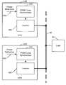
- FIG. 4illustrates a paralleled arrangement of UPSs 400 ′, 400 ′′ according to some embodiments of the invention.
- Each of the UPSs 400 ′, 400 ′′includes an inverter 420 that has an output coupled to an AC load bus 50 .
- the UPSs 400 ′, 400 ′′further include PWM cycle synchronizer circuits 410 that synchronize PWM cycles of the inverters 420 to a common phase reference 405 .
- the common phase reference 405may include, for example, respective phase-locked digital sinusoidal reference signals that are provided at each of the UPS's 400 ′, 400 ′′, and the PWM cycle synchronizer circuits 410 may comprise digitally-implemented phase-locked loops that phase locks PWM cycles of the inverters 420 to the sinusoidal reference signals.
- PWM cycle synchronizationmay be implemented in a number of different ways within the scope of the invention, including in analog, digital and mixed analog/digital implementations.
- FIGS. 5-10illustrate exemplary control structures and operations for providing PWM cycle synchronization according to some embodiments of the invention.
- the structures illustrated in FIGS. 5-10are illustrated as functional blocks that may be implemented using computer readable program code executing in processor, for example, in an integrated PWM-capable microcontroller, such that the microcontroller or other processor provides electronic circuitry that performs the indicated functions. It will be appreciated that analog and/or digital circuitry that provides similar functionality may be used in other embodiments of the invention. In various embodiments of the invention, circuitry such as that supported by FIGS.
- UPSsmay be may be used in paralleled UPSs with phase-locked sinusoidal reference signals to provide synchronization of the PWM cycles of the UPSs, and can additionally provide synchronization of data sampling for other functions, e.g., ancillary control functions other than PWM control functions. In this manner, the effects of harmonics on PWM and such other control functions can be reduced.
- the structureincludes a PWM loop control block 520 that provides PWM control outputs (e.g., IGBT gate drive signals) to a bridge circuit.
- the PWM loop control block 520receives sampled control inputs ⁇ ; i from an A/D converter block 510 at instants defined by an interrupt signal generated by an AC-synchronized PWM interrupt generator block 530 .
- the AC-synchronized PWM interrupt generator block 530generates the interrupt signal, which is also provided to the PWM loop control block 520 for timing of its PWM computation and control output cycles (PWM cycles), responsive to a clock signal produced by a clock generator block 540 , and synchronizes the interrupt signal to a reference sinusoidal signal generated by a reference sinusoidal signal generator block 550 .
- the reference sinusoidal signalmay represent, for example, a frequency and phase corresponding to an AC fundamental voltage on the AC load bus.
- the AC-synchronized interrupt signalmay also be used to sample inputs to an ancillary control block 560 , such that sampling of inputs to this control block are synchronized to the PWM cycles.
- FIG. 6illustrates an exemplary implementation of an AC-synchronized PWM interrupt generator 530 ′ according to further embodiments of the invention.
- a PWM counter block 534counts a PWM count cycle responsive to the system clock signal produced by the clock generator block 540 , generating an interrupt signal for each PWM cycle.
- the PWM count cycleis determined by an end (terminal) count END_COUNT supplied to the PWM counter 534 by a PWM count controller block 532 .
- the PWM counter blockmay be implemented in a number of ways, including using up and/or down counters and/or multiple counting stages.
- the PWM count controller block 532is operative to vary the terminal count END_COUNT based on comparison of the interrupts with the reference sinusoidal signal produced by the sinusoidal reference signal generator block 550 .
- a PWM cycle period(e.g., END_COUNT is initialized (block 705 ).
- a zero crossing of the sinusoidal reference signalis then detected (block 710 ) and, in response, a count of PWM cycles (interrupts) is initialized to zero (block 715 ).
- the value of the sinusoidal reference signalis checked (block 720 ). If no zero crossing is detected (block 725 , the PWM cycle count is incremented (block 730 ), and the PWM counter controller block 532 waits for the next PWM cycle to check the sinusoidal reference signal again (blocks 720 , 725 ).
- the PWM counter controller block 532Upon detection of a zero crossing (block 725 ), the PWM counter controller block 532 determines an integer cycle number error, representing a difference between a number of complete (integer) cycles actually falling between zero crossings and a predetermined number of complete cycles that should occur between zero crossings (block 735 ). The PWM counter controller block 532 also determines an intracycle error, which represents a portion of a PWM cycle separating the start (or other indicia) of the PWM cycle with respect to the detected zero crossing (Block 740 ).
- the control algorithmcould “anticipate” an upcoming zero crossing by detecting, responsive to an interrupt, that a value of the sinusoidal reference signal indicates that the next check of the reference signal will occur following a zero crossing. In either case, the fraction of a PWM cycle separating the zero crossing and the interrupt can be estimated from the value of the sinusoidal reference signal.
- a new PWM cycle periodmay be computed (block 745 ) and used to generate a new terminal count END_COUNT for the PWM Counter block 534 (block 750 ).
- the intracycle errormay need to be zeroed if the cycle number error and the intracycle error are both negative or both positive.
- the processes of blocks 715 - 750may then be repeated to continuously update the PWM cycle period such that the PWM cycles are phase locked to the sinusoidal reference signal. It will be appreciated that the PWM period may be further subjected to limits such that the PWM frequency may be kept within predetermined bounds if the sinusoidal reference signal becomes aberrant.
- FIG. 8is a diagram illustrating exemplary timing relationships among values produced by a digital sinusoidal reference signal reference signal generator and PWM cycles according to further embodiments of the invention.
- a PWM count PWM_COUNTis counted up from zero (0) to a terminal count END_COUNT and back down to zero in a PWM cycle, and successive sinusoidal reference signal values ⁇ i , ⁇ i+1 are produced by a digital sinusoidal reference signal generation algorithm once every four (4) of the PWM count cycles (0-END_COUNT).
- the 4 to 1 relationship shown in FIG. 8is exemplary, and that other relationships may be used with the invention.
- An actual zero crossing of the sinusoidal reference signalmay be “virtual,” e.g., the successive sinusoidal reference signal values ⁇ i , ⁇ i+1 may be values on opposite sides of a zero crossing.
- values of the sinusoidal reference signal other than an actual zero crossingmay be used to estimate, e.g., interpolate or extrapolate, the point in the 4 PWM count cycle interval at which the “virtual” zero crossing occurs, such that an accurate estimate of phase error of the PWM cycles can be determined and used to phase lock the PWM cycles to the sinusoidal reference signal.
- the location X of the zero crossingmay be obtained by interpolation using the successive sinusoidal reference signal values ⁇ i , ⁇ i+1 . It will be appreciated that this interpolation may be linear or have some other functional basis.
- a phase error valuemay then be determined by determining a distance (e.g., in counts) from the point X to a reference point Y of the PWM cycles at which it is desired for the zero crossing to coincide.
- This phase errormay be used to modify the terminal count value END_COUNT to lag or lead the PWM cycles such that the part of the PWM cycle corresponding to point Y is driven towards a zero crossing of the sinusoidal reference signal. It is assumed that each of the paralleled UPSs utilize the same reference point Y such that the same portions of their respective PWM cycles are locked to the zero crossings of the sinusoidal reference signal. It will be appreciated that the choice of the reference count Y is generally arbitrary, and that estimation techniques other than interpolation, such as extrapolation, may be used with the invention.
- FIG. 9illustrates exemplary operations for a PWM counter controller, such as the PWM counter controller 532 , according to some embodiments of the invention.
- An actual angle step valuerepresenting the number of degrees (or other angular measure) corresponding to a PWM cycle, is determined (block 905 ).
- the actual angle step valueis compared with an ideal angle step value, representing a desired angular increment, to determine a frequency error value (block 910 ).
- the actual angle stepmay be generated as part of a PWM control algorithm as described, for example, in U.S. patent application Ser. No.
- the angle step valuemay be accumulated (integrated) to provide an angle value that serves as a reference for a PWM controller.
- Sinusoidal reference signal values immediately preceding and following a zero crossingare determined (block 915 ), and value for this accumulated angle corresponding to the zero crossing of the sinusoidal reference signal is interpolated using the sinusoidal reference signal values and corresponding angle values (block 920 ).
- a phase erroris determined by determining a number of counts from the zero-crossing count value to a reference count value (block 925 ).
- the phase error e ⁇may be given by the following:
- PWM_COUNT refis the desired zero crossing point in the 4 PWM count cycle (e.g., point Y in FIG. 8 , which corresponds to 2 ⁇ the current terminal count END_COUNT)
- ⁇ actual,zcis the interpolated value of the accumulated (integrated) angle corresponding to the zero crossing of the sinusoidal reference signal.
- the PWM cycle lengthi.e., the terminal count END_COUNT, is updated based on the frequency error and the phase error (block 930 ).
- a master sinusoidal reference signalcould be provided to each UPS.
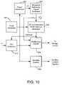
- sinusoidal reference signalscould be independently generated in each UPS as described, for example, in U.S. Pat. No. 5,745,356 to Tassitino et al., the disclosure of which is incorporated by reference in its entirety.
- the Tassitino et al. patentdescribes a technique whereby a sinusoidal reference signal for operation of a PWM inverter of a UPS can be generated by determining a derivative of real power being transferred by the inverter. In this manner, paralleled UPSs can autonomously achieve load sharing without requiring inter-unit signaling.
- a digitally-implemented control structure utilizing such a techniquemay include an A/D converter 510 , a PWM loop control block 520 , an AC-synchronized PWM interrupt generator block 530 , a clock generator block 540 and ancillary control block as described above with reference to FIG. 5 .
- a sinusoidal reference signal generator block 554generates a sinusoidal reference signal for the AC-synchronized PWM interrupt generator block 530 .
- the sinusoidal reference signalis also used by the PWM loop control block 520 to provide a reference for generation of an AC output voltage by the bridge circuit controlled by the PWM loop control block 520 .
- the sinusoidal reference signalis generated responsive to a power signal ⁇ P representative of a change in real power generated by a power determiner block 552 responsive to voltage and current data sampled by the A/D converter block 510 .
Landscapes
- Engineering & Computer Science (AREA)
- Power Engineering (AREA)
- Business, Economics & Management (AREA)
- Emergency Management (AREA)
- Inverter Devices (AREA)
Abstract
Description
ef=Δθideal−Δθactual, (1)
where Δθidealand Δθactualare the ideal and actual angle step values, respectively.
where PWM_COUNTrefis the desired zero crossing point in the 4 PWM count cycle (e.g., point Y in
Claims (35)
Priority Applications (1)
| Application Number | Priority Date | Filing Date | Title |
|---|---|---|---|
| US10/886,483US7405494B2 (en) | 2004-07-07 | 2004-07-07 | AC power supply apparatus, methods and computer program products using PWM synchronization |
Applications Claiming Priority (1)
| Application Number | Priority Date | Filing Date | Title |
|---|---|---|---|
| US10/886,483US7405494B2 (en) | 2004-07-07 | 2004-07-07 | AC power supply apparatus, methods and computer program products using PWM synchronization |
Publications (2)
| Publication Number | Publication Date |
|---|---|
| US20060006741A1 US20060006741A1 (en) | 2006-01-12 |
| US7405494B2true US7405494B2 (en) | 2008-07-29 |
Family
ID=35540568
Family Applications (1)
| Application Number | Title | Priority Date | Filing Date |
|---|---|---|---|
| US10/886,483Expired - Fee RelatedUS7405494B2 (en) | 2004-07-07 | 2004-07-07 | AC power supply apparatus, methods and computer program products using PWM synchronization |
Country Status (1)
| Country | Link |
|---|---|
| US (1) | US7405494B2 (en) |
Cited By (39)
| Publication number | Priority date | Publication date | Assignee | Title |
|---|---|---|---|---|
| US20080265680A1 (en)* | 2007-04-27 | 2008-10-30 | Liebert Corporation | Method for pulse width modulation synchronization in a parallel ups system |
| US20110084556A1 (en)* | 2009-10-09 | 2011-04-14 | Marroquin Marco A | System and apparatus for interconnecting an array of power generating assemblies |
| US20110083733A1 (en)* | 2009-10-12 | 2011-04-14 | SolarBridge Technologies | Power inverter docking system for photovoltaic modules |
| US8174856B2 (en) | 2011-04-27 | 2012-05-08 | Solarbridge Technologies, Inc. | Configurable power supply assembly |
| USD666974S1 (en) | 2010-09-24 | 2012-09-11 | Solarbridge Technologies, Inc. | Y-junction interconnect module |
| US8279649B2 (en) | 2010-10-11 | 2012-10-02 | Solarbridge Technologies, Inc. | Apparatus and method for controlling a power inverter |
| US8284574B2 (en) | 2011-10-17 | 2012-10-09 | Solarbridge Technologies, Inc. | Method and apparatus for controlling an inverter using pulse mode control |
| US8325499B2 (en) | 2007-10-11 | 2012-12-04 | Solarbridge Technologies, Inc. | Methods for minimizing double-frequency ripple power in single-phase power conditioners |
| US8503200B2 (en) | 2010-10-11 | 2013-08-06 | Solarbridge Technologies, Inc. | Quadrature-corrected feedforward control apparatus and method for DC-AC power conversion |
| US20130234641A1 (en)* | 2012-03-09 | 2013-09-12 | Delta Electronics, Inc. | Converter system |
| US8611107B2 (en) | 2011-04-27 | 2013-12-17 | Solarbridge Technologies, Inc. | Method and system for controlling a multi-stage power inverter |
| WO2014078348A1 (en) | 2012-11-15 | 2014-05-22 | Eaton Corporation | Ups systems and methods using ups modules with differential mode inductor coupling |
| USD707632S1 (en) | 2012-06-07 | 2014-06-24 | Enphase Energy, Inc. | Trunk connector |
| USD708143S1 (en) | 2012-06-07 | 2014-07-01 | Enphase Energy, Inc. | Drop cable connector |
| US8797767B2 (en) | 2011-05-20 | 2014-08-05 | Enphase Energy, Inc. | Resonant power conversion circuit |
| US8824178B1 (en) | 2009-12-31 | 2014-09-02 | Solarbridge Technologies, Inc. | Parallel power converter topology |
| US8842454B2 (en) | 2010-11-29 | 2014-09-23 | Solarbridge Technologies, Inc. | Inverter array with localized inverter control |
| US8892184B2 (en) | 2010-10-18 | 2014-11-18 | Siemens Medical Solutions Usa, Inc. | Systems and methods for reducing interference in a dual modality imaging system |
| US20140346869A1 (en)* | 2011-12-20 | 2014-11-27 | Mitsui Engineering & Shipbuilding Co., Ltd. | Emergency power supply method for container terminal and container terminal |
| US8922185B2 (en) | 2011-07-11 | 2014-12-30 | Solarbridge Technologies, Inc. | Device and method for global maximum power point tracking |
| US8963378B1 (en) | 2010-01-25 | 2015-02-24 | Enphase Energy, Inc. | Method and apparatus for interconnecting distributed power sources |
| US9048744B2 (en) | 2011-01-03 | 2015-06-02 | Enphase Energy, Inc. | Method and apparatus for resonant converter control |
| US9065354B2 (en) | 2011-04-27 | 2015-06-23 | Sunpower Corporation | Multi-stage power inverter for power bus communication |
| US9093919B2 (en) | 2009-07-31 | 2015-07-28 | Sunpower Corporation | Apparatus for converting direct current to alternating current using a frequency converter |
| US20150263566A1 (en)* | 2014-03-11 | 2015-09-17 | General Electric Company | Redundant uninterruptible power supply systems |
| US9160408B2 (en) | 2010-10-11 | 2015-10-13 | Sunpower Corporation | System and method for establishing communication with an array of inverters |
| US9276635B2 (en) | 2012-06-29 | 2016-03-01 | Sunpower Corporation | Device, system, and method for communicating with a power inverter using power line communications |
| CN105471058A (en)* | 2014-08-22 | 2016-04-06 | 比亚迪股份有限公司 | Charging control system and charging method thereof |
| US9444367B2 (en) | 2011-05-26 | 2016-09-13 | Enphase Energy, Inc. | Method and apparatus for generating single-phase power from a three-phase resonant power converter |
| US9467063B2 (en) | 2010-11-29 | 2016-10-11 | Sunpower Corporation | Technologies for interleaved control of an inverter array |
| US9479082B2 (en) | 2011-01-04 | 2016-10-25 | Enphase Energy, Inc. | Method and apparatus for resonant power conversion |
| US9564835B2 (en) | 2013-03-15 | 2017-02-07 | Sunpower Corporation | Inverter communications using output signal |
| US9584044B2 (en) | 2013-03-15 | 2017-02-28 | Sunpower Corporation | Technologies for converter topologies |
| US9705360B2 (en) | 2014-03-11 | 2017-07-11 | General Electric Company | Redundant uninterruptible power supply systems |
| US9806445B2 (en) | 2010-01-25 | 2017-10-31 | Enphase Energy, Inc. | Method and apparatus for interconnecting distributed power sources |
| US9948204B2 (en) | 2011-05-19 | 2018-04-17 | Enphase Energy, Inc. | Method and apparatus for controlling resonant converter output power |
| US10277066B2 (en) | 2015-04-15 | 2019-04-30 | Vertiv Corporation | Method for balancing power in paralleled converters |
| US10291028B2 (en) | 2016-07-29 | 2019-05-14 | Cummins Power Generation Ip, Inc. | Masterless distributed power transfer control |
| US10418817B2 (en) | 2016-07-29 | 2019-09-17 | Cummins Power Generation Ip, Inc. | Synchronization of parallel gensets with source arbitration |
Families Citing this family (17)
| Publication number | Priority date | Publication date | Assignee | Title |
|---|---|---|---|---|
| JP2007267505A (en)* | 2006-03-28 | 2007-10-11 | Toshiba Corp | Power supply control apparatus, electronic device, and power supply control method |
| WO2009104166A1 (en)* | 2008-02-20 | 2009-08-27 | Frans Gustav Theodor Radloff | Energy consumption management |
| DE102010038735B3 (en)* | 2010-07-30 | 2011-11-17 | Semikron Elektronik Gmbh & Co. Kg | Method for operating a PWM output of a driver for a power semiconductor |
| US9548610B2 (en) | 2010-09-14 | 2017-01-17 | Ingeteam Power Technology, S.A. | Control method for arranging DC/AC converters in parallel |
| CA2829166A1 (en)* | 2011-03-16 | 2012-09-20 | Sma Solar Technology Ag | Grid-connected inverter, inverter arrangement and method for operating an inverter arrangement |
| CN102594309A (en)* | 2012-03-31 | 2012-07-18 | 中国科学院上海应用物理研究所 | Synchronization method for pulse width modulation |
| DE102012024560B3 (en) | 2012-12-17 | 2014-03-27 | B2 Electronic Gmbh | Circuit arrangement and method for generating a test voltage and test apparatus for determining a loss factor, which contains the circuit arrangement |
| US9484745B2 (en)* | 2013-09-09 | 2016-11-01 | Rutgers, The State University Of New Jersey | Virtual oscillator control of power electronics inverters |
| US9882424B2 (en) | 2014-02-21 | 2018-01-30 | General Electric Company | Redundant uninterruptible power supply systems |
| CN105187037B (en)* | 2014-05-28 | 2018-09-28 | 台达电子工业股份有限公司 | Pulse width modulation system control method and its error action preventing circuit |
| DE102014119502B3 (en)* | 2014-12-23 | 2016-03-24 | Sma Solar Technology Ag | Grid connected inverter, inverter arrangement and operating method for an inverter arrangement |
| US9859716B2 (en) | 2015-05-29 | 2018-01-02 | General Electric Company | Hybrid AC and DC distribution system and method of use |
| US9859752B2 (en) | 2015-06-05 | 2018-01-02 | General Electric Company | Uninterruptible power supply and method of use |
| WO2017045702A1 (en)* | 2015-09-15 | 2017-03-23 | Green Power Technologies, S. L. | System for converting power |
| CN111181249B (en)* | 2020-02-17 | 2025-02-18 | 佛山市科蓝环保科技股份有限公司 | Synchronization method for multiple power supplies in parallel, control power supply, electric control device and purifier |
| AT523994B1 (en)* | 2020-06-16 | 2022-07-15 | Avl List Gmbh | Measuring arrangement for a converter and converter arrangement |
| US11356238B1 (en) | 2021-05-24 | 2022-06-07 | Texas Instruments Incorporated | Synchronization between devices for PWM waveforms |
Citations (7)
| Publication number | Priority date | Publication date | Assignee | Title |
|---|---|---|---|---|
| US4733341A (en)* | 1985-12-20 | 1988-03-22 | Kabushiki Kaisha Toshiba | Plural inverter synchronizer and control apparatus |
| US5745356A (en) | 1996-06-25 | 1998-04-28 | Exide Electronics Corporation | Independent load sharing of AC power systems connected in parallel |
| US6118680A (en)* | 1999-05-28 | 2000-09-12 | Peco Ii | Methods and apparatus for load sharing between parallel inverters in an AC power supply |
| US6381157B2 (en)* | 2000-01-06 | 2002-04-30 | Axel Akerman A/S | Independent load sharing between parallel inverter units in an AC power system |
| US20050286274A1 (en)* | 2004-06-29 | 2005-12-29 | Hans-Erik Pfitzer | Self-testing power supply apparatus, methods and computer program products |
| US7002384B1 (en)* | 2004-01-16 | 2006-02-21 | Altera Corporation | Loop circuitry with low-pass noise filter |
| US20060215064A1 (en)* | 2005-03-24 | 2006-09-28 | Dawson Francis P | Method and system for wide-range synchronization to alternating current power signals |
- 2004
- 2004-07-07USUS10/886,483patent/US7405494B2/ennot_activeExpired - Fee Related
Patent Citations (7)
| Publication number | Priority date | Publication date | Assignee | Title |
|---|---|---|---|---|
| US4733341A (en)* | 1985-12-20 | 1988-03-22 | Kabushiki Kaisha Toshiba | Plural inverter synchronizer and control apparatus |
| US5745356A (en) | 1996-06-25 | 1998-04-28 | Exide Electronics Corporation | Independent load sharing of AC power systems connected in parallel |
| US6118680A (en)* | 1999-05-28 | 2000-09-12 | Peco Ii | Methods and apparatus for load sharing between parallel inverters in an AC power supply |
| US6381157B2 (en)* | 2000-01-06 | 2002-04-30 | Axel Akerman A/S | Independent load sharing between parallel inverter units in an AC power system |
| US7002384B1 (en)* | 2004-01-16 | 2006-02-21 | Altera Corporation | Loop circuitry with low-pass noise filter |
| US20050286274A1 (en)* | 2004-06-29 | 2005-12-29 | Hans-Erik Pfitzer | Self-testing power supply apparatus, methods and computer program products |
| US20060215064A1 (en)* | 2005-03-24 | 2006-09-28 | Dawson Francis P | Method and system for wide-range synchronization to alternating current power signals |
Non-Patent Citations (2)
| Title |
|---|
| Chen et al., "The Burn-in Test of Three-Phase UPS by Energy Feedback Method," IEEE, 1993, pp. 766-771. |
| Chu et al., "Self-load bank for UPS testing by circulating current method," IEE Proc.-Electr. Power Appl., vol. 141, No. 4, Jul. 1994, pp. 191-196. |
Cited By (65)
| Publication number | Priority date | Publication date | Assignee | Title |
|---|---|---|---|---|
| US7667351B2 (en)* | 2007-04-27 | 2010-02-23 | Liebert Corporation | Method for pulse width modulation synchronization in a parallel UPS system |
| US20080265680A1 (en)* | 2007-04-27 | 2008-10-30 | Liebert Corporation | Method for pulse width modulation synchronization in a parallel ups system |
| US8325499B2 (en) | 2007-10-11 | 2012-12-04 | Solarbridge Technologies, Inc. | Methods for minimizing double-frequency ripple power in single-phase power conditioners |
| US9225256B2 (en) | 2009-07-31 | 2015-12-29 | Sunpower Corporation | Apparatus and method for controlling DC-AC power conversion |
| US9093919B2 (en) | 2009-07-31 | 2015-07-28 | Sunpower Corporation | Apparatus for converting direct current to alternating current using a frequency converter |
| US20110084556A1 (en)* | 2009-10-09 | 2011-04-14 | Marroquin Marco A | System and apparatus for interconnecting an array of power generating assemblies |
| US8207637B2 (en)* | 2009-10-09 | 2012-06-26 | Solarbridge Technologies, Inc. | System and apparatus for interconnecting an array of power generating assemblies |
| US8227942B2 (en)* | 2009-10-09 | 2012-07-24 | Solarbridge Technologies, Inc. | System and apparatus for interconnecting an array of power generating assemblies |
| US20120104872A1 (en)* | 2009-10-09 | 2012-05-03 | Marroquin Marco A | System and Apparatus for Interconnecting and Array of Power Generating Assemblies |
| US8929094B2 (en) | 2009-10-12 | 2015-01-06 | Solarbridge Technologies, Inc. | Power inverter docking system for photovoltaic modules |
| US20110083733A1 (en)* | 2009-10-12 | 2011-04-14 | SolarBridge Technologies | Power inverter docking system for photovoltaic modules |
| US8462518B2 (en) | 2009-10-12 | 2013-06-11 | Solarbridge Technologies, Inc. | Power inverter docking system for photovoltaic modules |
| US8824178B1 (en) | 2009-12-31 | 2014-09-02 | Solarbridge Technologies, Inc. | Parallel power converter topology |
| US8963378B1 (en) | 2010-01-25 | 2015-02-24 | Enphase Energy, Inc. | Method and apparatus for interconnecting distributed power sources |
| US9806445B2 (en) | 2010-01-25 | 2017-10-31 | Enphase Energy, Inc. | Method and apparatus for interconnecting distributed power sources |
| USD666974S1 (en) | 2010-09-24 | 2012-09-11 | Solarbridge Technologies, Inc. | Y-junction interconnect module |
| US8503200B2 (en) | 2010-10-11 | 2013-08-06 | Solarbridge Technologies, Inc. | Quadrature-corrected feedforward control apparatus and method for DC-AC power conversion |
| US9160408B2 (en) | 2010-10-11 | 2015-10-13 | Sunpower Corporation | System and method for establishing communication with an array of inverters |
| US8279649B2 (en) | 2010-10-11 | 2012-10-02 | Solarbridge Technologies, Inc. | Apparatus and method for controlling a power inverter |
| US8817510B2 (en) | 2010-10-11 | 2014-08-26 | Solarbridge Technologies, Inc. | Apparatus and method for controlling a power inverter |
| US10483795B2 (en) | 2010-10-11 | 2019-11-19 | Enphase Energy, Inc. | System and method for establishing communication with an array of inverters |
| US8892184B2 (en) | 2010-10-18 | 2014-11-18 | Siemens Medical Solutions Usa, Inc. | Systems and methods for reducing interference in a dual modality imaging system |
| US9467063B2 (en) | 2010-11-29 | 2016-10-11 | Sunpower Corporation | Technologies for interleaved control of an inverter array |
| US8842454B2 (en) | 2010-11-29 | 2014-09-23 | Solarbridge Technologies, Inc. | Inverter array with localized inverter control |
| US9048744B2 (en) | 2011-01-03 | 2015-06-02 | Enphase Energy, Inc. | Method and apparatus for resonant converter control |
| US9479082B2 (en) | 2011-01-04 | 2016-10-25 | Enphase Energy, Inc. | Method and apparatus for resonant power conversion |
| US10141868B2 (en) | 2011-01-04 | 2018-11-27 | Enphase Energy, Inc. | Method and apparatus for resonant power conversion |
| US8461813B2 (en) | 2011-04-27 | 2013-06-11 | Solarbridge Technologies Inc. | Method and device for controlling a configurable power supply to provide AC and/or DC power output |
| US8193788B2 (en) | 2011-04-27 | 2012-06-05 | Solarbridge Technologies, Inc. | Method and device for controlling a configurable power supply to provide AC and/or DC power output |
| US8174856B2 (en) | 2011-04-27 | 2012-05-08 | Solarbridge Technologies, Inc. | Configurable power supply assembly |
| US8456876B2 (en) | 2011-04-27 | 2013-06-04 | Solarbridge Technologies, Inc. | Configurable power supply assembly |
| US9263183B2 (en) | 2011-04-27 | 2016-02-16 | Sunpower Corporation | Modular photovoltaic power supply assembly |
| US8599587B2 (en) | 2011-04-27 | 2013-12-03 | Solarbridge Technologies, Inc. | Modular photovoltaic power supply assembly |
| US8611107B2 (en) | 2011-04-27 | 2013-12-17 | Solarbridge Technologies, Inc. | Method and system for controlling a multi-stage power inverter |
| US9065354B2 (en) | 2011-04-27 | 2015-06-23 | Sunpower Corporation | Multi-stage power inverter for power bus communication |
| US9948204B2 (en) | 2011-05-19 | 2018-04-17 | Enphase Energy, Inc. | Method and apparatus for controlling resonant converter output power |
| US8797767B2 (en) | 2011-05-20 | 2014-08-05 | Enphase Energy, Inc. | Resonant power conversion circuit |
| US9379627B2 (en) | 2011-05-20 | 2016-06-28 | Enphase Energy, Inc. | Power conversion circuit arrangements utilizing resonant alternating current linkage |
| US9444367B2 (en) | 2011-05-26 | 2016-09-13 | Enphase Energy, Inc. | Method and apparatus for generating single-phase power from a three-phase resonant power converter |
| US10050446B2 (en) | 2011-07-11 | 2018-08-14 | Sunpower Corporation | Device and method for global maximum power point tracking |
| US8922185B2 (en) | 2011-07-11 | 2014-12-30 | Solarbridge Technologies, Inc. | Device and method for global maximum power point tracking |
| US8284574B2 (en) | 2011-10-17 | 2012-10-09 | Solarbridge Technologies, Inc. | Method and apparatus for controlling an inverter using pulse mode control |
| US8737100B2 (en) | 2011-10-17 | 2014-05-27 | Solarbridge Technologies, Inc. | Method and apparatus for controlling an inverter using pulse mode control |
| US20140346869A1 (en)* | 2011-12-20 | 2014-11-27 | Mitsui Engineering & Shipbuilding Co., Ltd. | Emergency power supply method for container terminal and container terminal |
| US10033187B2 (en)* | 2011-12-20 | 2018-07-24 | Mitsui Engineering & Shipbuilding Co., Ltd. | Emergency power supply method for container terminal and container terminal |
| US20130234641A1 (en)* | 2012-03-09 | 2013-09-12 | Delta Electronics, Inc. | Converter system |
| US8917047B2 (en)* | 2012-03-09 | 2014-12-23 | Delta Electronics, Inc. | Converter system |
| USD708143S1 (en) | 2012-06-07 | 2014-07-01 | Enphase Energy, Inc. | Drop cable connector |
| USD707632S1 (en) | 2012-06-07 | 2014-06-24 | Enphase Energy, Inc. | Trunk connector |
| US9276635B2 (en) | 2012-06-29 | 2016-03-01 | Sunpower Corporation | Device, system, and method for communicating with a power inverter using power line communications |
| WO2014078348A1 (en) | 2012-11-15 | 2014-05-22 | Eaton Corporation | Ups systems and methods using ups modules with differential mode inductor coupling |
| US9564835B2 (en) | 2013-03-15 | 2017-02-07 | Sunpower Corporation | Inverter communications using output signal |
| US9584044B2 (en) | 2013-03-15 | 2017-02-28 | Sunpower Corporation | Technologies for converter topologies |
| US10404190B2 (en) | 2013-03-15 | 2019-09-03 | Enphase Energy, Inc. | Inverter communications using output signal |
| US9685820B2 (en)* | 2014-03-11 | 2017-06-20 | General Electric Company | Redundant uninterruptible power supply systems |
| US9705360B2 (en) | 2014-03-11 | 2017-07-11 | General Electric Company | Redundant uninterruptible power supply systems |
| US20150263566A1 (en)* | 2014-03-11 | 2015-09-17 | General Electric Company | Redundant uninterruptible power supply systems |
| CN105471058A (en)* | 2014-08-22 | 2016-04-06 | 比亚迪股份有限公司 | Charging control system and charging method thereof |
| CN105471058B (en)* | 2014-08-22 | 2019-02-26 | 比亚迪股份有限公司 | Charging control system and charging method thereof |
| US10277066B2 (en) | 2015-04-15 | 2019-04-30 | Vertiv Corporation | Method for balancing power in paralleled converters |
| US10291028B2 (en) | 2016-07-29 | 2019-05-14 | Cummins Power Generation Ip, Inc. | Masterless distributed power transfer control |
| US10418817B2 (en) | 2016-07-29 | 2019-09-17 | Cummins Power Generation Ip, Inc. | Synchronization of parallel gensets with source arbitration |
| US10992138B2 (en) | 2016-07-29 | 2021-04-27 | Cummins Power Generation Ip, Inc. | Masterless distributed power transfer control |
| US11563326B2 (en) | 2016-07-29 | 2023-01-24 | Cummins Power Generation Ip, Inc. | Synchronization of parallel gensets with source arbitration |
| US11689052B2 (en) | 2016-07-29 | 2023-06-27 | Cummins Power Generation Ip, Inc. | Masterless distributed power transfer control |
Also Published As
| Publication number | Publication date |
|---|---|
| US20060006741A1 (en) | 2006-01-12 |
Similar Documents
| Publication | Publication Date | Title |
|---|---|---|
| US7405494B2 (en) | AC power supply apparatus, methods and computer program products using PWM synchronization | |
| US7230837B1 (en) | Method and circuit for cascaded pulse width modulation | |
| US6828753B2 (en) | Input filter for A.C. motor phase current sensing | |
| KR20100137549A (en) | DC bus voltage harmonic reduction | |
| KR960005691B1 (en) | Power converter | |
| US20080180095A1 (en) | Method and related device for estimating the currents flowing in windings of a poly-phase electrical load at a certain instant | |
| EP3125420A1 (en) | Power conversion device | |
| JP2008040664A (en) | Inverter device and pwm control method for this inverter device | |
| Zhou et al. | Time delay compensation-based fast current controller for active power filters | |
| US7831402B2 (en) | Method and related device for estimating two currents flowing simultaneously through respective windings of a poly-phase electrical load driven in SVM mode | |
| US7561451B2 (en) | Power converter apparatus and methods using a phase reference derived from a DC bus voltage | |
| CN116097537A (en) | Apparatus and method for improved grid synchronization of unidirectional power converters | |
| JP3229520B2 (en) | Phase rotation abnormality detection device | |
| JP2003102131A (en) | System linking power converting apparatus and method for controlling the same | |
| JP2913889B2 (en) | Predictive instantaneous value control method for PWM inverter | |
| JP2019068559A (en) | Power converter and power conversion system | |
| KR101633340B1 (en) | An apparatus and a method for control of the neutral point in an uninterruptible power supply | |
| Bommegowda et al. | Single phase inverter control with capacitor current feedback | |
| JP2626274B2 (en) | Inverter | |
| Dao et al. | Sensorless speed control of diesel-generator systems based on multiple SOGI-FLLs | |
| He et al. | Grid voltage sensorless control of three-phase LCL grid-connected inverters using multisampled current | |
| Lu et al. | A comparative benchmark of digital delay compensation techniques based on a graphical approach | |
| Grekov et al. | Synchronization of pulse-width modulation of the active rectifiers connected in parallel | |
| Wang et al. | Dc-bus voltage control of three-phase ac/dc converter using load predictive method | |
| Blasko | Interaction between power converter and control-PWM and sampling issues |
Legal Events
| Date | Code | Title | Description |
|---|---|---|---|
| AS | Assignment | Owner name:POWERWARE CORPORATION, NORTH CAROLINA Free format text:ASSIGNMENT OF ASSIGNORS INTEREST;ASSIGNORS:TASSITINO JR., FREDERICK;PFITZER, HANS-ERIK;ANDERSON, JASON S.;AND OTHERS;REEL/FRAME:015084/0255 Effective date:20040701 | |
| AS | Assignment | Owner name:EATON POWER QUALITY LIMITED, OHIO Free format text:ASSIGNMENT OF ASSIGNORS INTEREST;ASSIGNOR:POWERWARE CORPORATION;REEL/FRAME:020797/0387 Effective date:20041027 Owner name:EATON ELECTRICAL INC., OHIO Free format text:CHANGE OF NAME;ASSIGNOR:EATON POWER QUALITY CORPORATION;REEL/FRAME:020797/0392 Effective date:20060428 Owner name:EATON CORPORATION, OHIO Free format text:CERTIFICATE;ASSIGNOR:EATON ELECTRICAL INC.;REEL/FRAME:020797/0474 Effective date:20080117 | |
| REMI | Maintenance fee reminder mailed | ||
| LAPS | Lapse for failure to pay maintenance fees | ||
| STCH | Information on status: patent discontinuation | Free format text:PATENT EXPIRED DUE TO NONPAYMENT OF MAINTENANCE FEES UNDER 37 CFR 1.362 | |
| FP | Lapsed due to failure to pay maintenance fee | Effective date:20120729 |