US7402769B2 - Vehicle occupant sensing system having a retention member for a biasing member - Google Patents
Vehicle occupant sensing system having a retention member for a biasing memberDownload PDFInfo
- Publication number
- US7402769B2 US7402769B2US11/085,915US8591505AUS7402769B2US 7402769 B2US7402769 B2US 7402769B2US 8591505 AUS8591505 AUS 8591505AUS 7402769 B2US7402769 B2US 7402769B2
- Authority
- US
- United States
- Prior art keywords
- base
- upper slide
- slide member
- sensing system
- vehicle occupant
- Prior art date
- Legal status (The legal status is an assumption and is not a legal conclusion. Google has not performed a legal analysis and makes no representation as to the accuracy of the status listed.)
- Expired - Fee Related, expires
Links
Images


Classifications
- B—PERFORMING OPERATIONS; TRANSPORTING
- B60—VEHICLES IN GENERAL
- B60R—VEHICLES, VEHICLE FITTINGS, OR VEHICLE PARTS, NOT OTHERWISE PROVIDED FOR
- B60R21/00—Arrangements or fittings on vehicles for protecting or preventing injuries to occupants or pedestrians in case of accidents or other traffic risks
- B60R21/01—Electrical circuits for triggering passive safety arrangements, e.g. airbags, safety belt tighteners, in case of vehicle accidents or impending vehicle accidents
- B60R21/015—Electrical circuits for triggering passive safety arrangements, e.g. airbags, safety belt tighteners, in case of vehicle accidents or impending vehicle accidents including means for detecting the presence or position of passengers, passenger seats or child seats, and the related safety parameters therefor, e.g. speed or timing of airbag inflation in relation to occupant position or seat belt use
- B60R21/01512—Passenger detection systems
- B60R21/01516—Passenger detection systems using force or pressure sensing means
- B—PERFORMING OPERATIONS; TRANSPORTING
- B60—VEHICLES IN GENERAL
- B60N—SEATS SPECIALLY ADAPTED FOR VEHICLES; VEHICLE PASSENGER ACCOMMODATION NOT OTHERWISE PROVIDED FOR
- B60N2/00—Seats specially adapted for vehicles; Arrangement or mounting of seats in vehicles
- B60N2/002—Seats provided with an occupancy detection means mounted therein or thereon
- B60N2/0021—Seats provided with an occupancy detection means mounted therein or thereon characterised by the type of sensor or measurement
- B60N2/0024—Seats provided with an occupancy detection means mounted therein or thereon characterised by the type of sensor or measurement for identifying, categorising or investigation of the occupant or object on the seat
- B60N2/0025—Seats provided with an occupancy detection means mounted therein or thereon characterised by the type of sensor or measurement for identifying, categorising or investigation of the occupant or object on the seat by using weight measurement
- B—PERFORMING OPERATIONS; TRANSPORTING
- B60—VEHICLES IN GENERAL
- B60N—SEATS SPECIALLY ADAPTED FOR VEHICLES; VEHICLE PASSENGER ACCOMMODATION NOT OTHERWISE PROVIDED FOR
- B60N2/00—Seats specially adapted for vehicles; Arrangement or mounting of seats in vehicles
- B60N2/002—Seats provided with an occupancy detection means mounted therein or thereon
- B60N2/0021—Seats provided with an occupancy detection means mounted therein or thereon characterised by the type of sensor or measurement
- B60N2/0024—Seats provided with an occupancy detection means mounted therein or thereon characterised by the type of sensor or measurement for identifying, categorising or investigation of the occupant or object on the seat
- B60N2/0027—Seats provided with an occupancy detection means mounted therein or thereon characterised by the type of sensor or measurement for identifying, categorising or investigation of the occupant or object on the seat for detecting the position of the occupant or of occupant's body part
- B—PERFORMING OPERATIONS; TRANSPORTING
- B60—VEHICLES IN GENERAL
- B60N—SEATS SPECIALLY ADAPTED FOR VEHICLES; VEHICLE PASSENGER ACCOMMODATION NOT OTHERWISE PROVIDED FOR
- B60N2/00—Seats specially adapted for vehicles; Arrangement or mounting of seats in vehicles
- B60N2/002—Seats provided with an occupancy detection means mounted therein or thereon
- B60N2/0021—Seats provided with an occupancy detection means mounted therein or thereon characterised by the type of sensor or measurement
- B60N2/003—Seats provided with an occupancy detection means mounted therein or thereon characterised by the type of sensor or measurement characterised by the sensor mounting location in or on the seat
- B60N2/0031—Seats provided with an occupancy detection means mounted therein or thereon characterised by the type of sensor or measurement characterised by the sensor mounting location in or on the seat mounted on the frame
- G—PHYSICS
- G01—MEASURING; TESTING
- G01G—WEIGHING
- G01G19/00—Weighing apparatus or methods adapted for special purposes not provided for in the preceding groups
- G01G19/40—Weighing apparatus or methods adapted for special purposes not provided for in the preceding groups with provisions for indicating, recording, or computing price or other quantities dependent on the weight
- G01G19/413—Weighing apparatus or methods adapted for special purposes not provided for in the preceding groups with provisions for indicating, recording, or computing price or other quantities dependent on the weight using electromechanical or electronic computing means
- G01G19/414—Weighing apparatus or methods adapted for special purposes not provided for in the preceding groups with provisions for indicating, recording, or computing price or other quantities dependent on the weight using electromechanical or electronic computing means using electronic computing means only
- G01G19/4142—Weighing apparatus or methods adapted for special purposes not provided for in the preceding groups with provisions for indicating, recording, or computing price or other quantities dependent on the weight using electromechanical or electronic computing means using electronic computing means only for controlling activation of safety devices, e.g. airbag systems
- B—PERFORMING OPERATIONS; TRANSPORTING
- B60—VEHICLES IN GENERAL
- B60N—SEATS SPECIALLY ADAPTED FOR VEHICLES; VEHICLE PASSENGER ACCOMMODATION NOT OTHERWISE PROVIDED FOR
- B60N2210/00—Sensor types, e.g. for passenger detection systems or for controlling seats
- B60N2210/10—Field detection presence sensors
- B60N2210/14—Inductive; Magnetic field
Definitions
- the present inventionrelates, generally, to a vehicle occupant sensing system, and more particularly, to a vehicle occupant sensing system having a retention member for a biasing member.
- Automotive vehiclesemploy seating systems that accommodate the passengers of the vehicle.
- the seating systemsinclude restraint systems that are calculated to restrain and protect the occupants in the event of a collision.
- the primary restraint system commonly employed in most vehicles todayis the seatbelt.
- Seatbeltsusually include a lap belt and a shoulder belt that extends diagonally across the occupant's torso from one end of the lap belt to a mounting structure located proximate to the occupant's opposite shoulder.
- automotive vehiclesmay include supplemental restraint systems.
- the most common supplemental restraint system employed in automotive vehicles todayis the inflatable airbag.
- the airbagsIn the event of a collision, the airbags are deployed as an additional means of restraining and protecting the occupants of the vehicle.
- the supplemental inflatable restraintswere deployed in the event of a collision whether or not any given seat was occupied.
- These supplemental inflatable restraints and their associated deployment systemsare expensive and over time this deployment strategy was deemed not to be cost effective.
- vehicle safety systemsinclude vehicle occupant sensing systems capable of detecting whether or not a given seat is occupied.
- the systemsact as a switch in controlling the deployment of a corresponding air bag. If the occupant sensing device detects that a seat is unoccupied during a collision, it can prevent the corresponding air bag from deploying, thereby saving the vehicle owner the unnecessary cost of replacing the expended air bag.
- One necessary component of each of the known systems discussed aboveincludes some means for sensing the presence of the vehicle occupant in the seat.
- One such meansmay include a sensor device supported within the lower seat cushion of the vehicle seat.
- published U.S. patent applicationhaving U.S. Ser. No. 10/249,527 and Publication No. US2003/0196495 A1 filed in the name of Saunders et al. discloses a method and apparatus for sensing seat occupancy including a sensor/emitter pair that is supported within a preassembled one-piece cylinder-shaped housing. The housing is adapted to be mounted within the seat cushion in a hole extending from the B-surface toward the A-surface of the seat cushion.
- the sensor/emitter pair supported in the housingincludes an emitter and a sensor spaced below the emitter.
- the cylindrical housingis formed of a compressible, rubber-like material that is responsive to loads placed on the upper surface of the seat cushion. The housing compresses in response to a load on the seat cushion. The load is detected through movement of the emitter toward the sensor as the housing is compressed. The housing is sufficiently resilient to restore the emitter to full height when no load is applied to the upper surface of the seat cushion.
- the Saunders et al. systemalso includes a processor for receiving the sensor signals and interpreting the signals to produce an output to indicate the presence of an occupant in the seat.
- the Saunders et al. occupant seat sensing systemmay sense the presence of a vehicle seat occupant, it suffers from certain disadvantages.
- the housingmay flex in an undesired manner in response to loading of the seat cushion, thereby causing excess signal noise and degrading the accuracy of the system.
- the emittermay also become detached from the housing, especially after repeated flexure of the housing, thereby causing the system to malfunction.
- the housing and sensor/emitter pairmay be difficult to assemble.
- the present inventionovercomes the disadvantages in the related art in a vehicle occupant sensing system for detecting a condition of a vehicle seat assembly that includes at least one base and at least one upper slide member supported for movement toward and away from the base.
- the upper slide memberis movable in response to the condition of the vehicle seat assembly.
- the vehicle occupant sensing systemfurther includes at least one biasing member for biasing the upper slide member away from the base.
- At least one of the base and the upper slide memberincludes at least one retention member that is adapted for retaining the biasing member.
- the vehicle occupant sensing systemmay be employed in a vehicle seat assembly to detect a condition of the vehicle seat.
- the retention membersretain the biasing member in a more secure manner.
- the vehicle occupant sensing systemcan be assembled more easily and the vehicle occupant sensing system has a longer operational life.
- the retention membersalso reduce friction during movement of the upper slide member, thereby reducing signal noise. As such, the vehicle occupant sensing system can more accurately monitor the condition of the vehicle seat assembly.
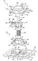
- FIG. 1is an exploded view of a vehicle seat assembly incorporating a vehicle occupant sensing system adapted for detecting a condition of the vehicle seat assembly;
- FIG. 2is an exploded view of one embodiment of a sensor assembly suitable for use in the vehicle occupant sensing system illustrated in FIG. 1 ;
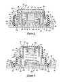
- FIG. 3is a cross-sectional side view of the sensor assembly of FIG. 2 shown in a compressed state
- FIG. 4is a cross-sectional side view of the sensor assembly of FIG. 2 shown in an uncompressed state
- FIG. 5is an exploded top view of another embodiment of a vehicle occupant sensing system including retention members
- FIG. 6is an exploded bottom view of the vehicle occupant sensing system of FIG. 5 ;
- FIG. 7is a cross-sectional side view of the sensor assembly of FIG. 5 ;
- FIG. 8is a cross-sectional side view of the sensor assembly of FIG. 7 taken along the line 8 - 8 .
- the vehicle seat assembly 10includes a seat back, generally indicated at 12 , and a lower seat assembly, generally indicated at 14 .
- the lower seat assembly 14has a seat cushion 16 with an upper surface 18 and a lower surface 20 that is spaced from the upper surface 18 .
- the upper surface 18 of the seat cushion 16may be referred to as the “A-surface” and the lower surface 20 may be referred to as the “B-surface.”
- the seat cushion 16also defines an inboard side 22 and an outboard side 24 .
- the weight of the occupantWhen an occupant (not shown) is supported on the lower seat assembly 14 , the weight of the occupant will apply an axial load directed generally through the upper surface 18 of the seat cushion 16 toward the lower surface 20 . Although the weight of the occupant will induce an axial as well as shear forces in the seat cushion 16 , those having ordinary skill in the art will recognize that the primary load path of the occupant's weight will be substantially vertical from the upper surface 18 toward the lower surface 20 , through the seat cushion 16 .
- the lower seat assembly 14also includes a seat pan, generally indicated at 26 .
- the seat pan 26is generally disposed beneath the lower surface 18 so as to support the seat cushion 16 .
- the seat pan 26is operatively supported relative to the floor of the vehicle using any suitable structure of the type commonly known in the art, such as a seat track (not shown).
- the vehicle seat assembly 10includes a vehicle occupant sensing system, generally indicated at 28 and disposed adjacent the lower surface 20 of the seat cushion 16 .
- the vehicle occupant sensing system 28is used for detecting a condition of the vehicle seat assembly 10 , such as whether or not the vehicle seat assembly 10 is occupied, whether the occupant is above or below a certain weight requirement, or whether the occupant is sitting in a certain position.
- the sensing system 28includes a circuit carrier tray, generally indicated at 30 , that is supported by the seat pan 26 .
- the tray 30includes an upper surface 32 adjacent the lower surface 20 of the seat cushion 16 .
- the tray 30is of the type described in detail in applicant's co-pending patent application Ser. No. 10/749,169, entitled “Vehicle Occupant Sensing System Having Circuit Carrier Tray,” which is incorporated herein in its entirety by reference.
- the tray 30supports components of the vehicle occupant sensing system 28 as will be described in greater detail below.
- the vehicle occupant sensing system 28also includes a circuit carrier 34 , which is disposed adjacent the lower surface 20 of the seat cushion 16 .
- the tray 30supports the circuit carrier 34 on the upper surface 32 .
- the vehicle occupant sensing system 28also includes an electric circuit 36 , which is supported by the circuit carrier 34 .
- the circuit carrier 34is made of a thin nonconductive and corrosion-resistant material, and it encapsulates known electrical components that form the electric circuit 36 .
- a flexible printed circuitforms the circuit carrier 34 and electric circuit 36 .
- the circuit 36is electrically connected to a controller schematically illustrated at 38 .
- the electric circuit 38carries electric signals generated by the vehicle occupant sensing system 28 to the controller 38 .
- the controller 38is electrically attached to a restraint system, schematically illustrated at 40 .
- the restraint system 40can be of many types, such as an inflatable restraint system, and the controller 38 sends output to the restraint system 40 based on the signals delivered by the electric circuit 36 . Although an inflatable restraint system is discussed here, one having ordinary skill in the art will recognize that the type of restraint system 40 connected to the controller 38 does not limit the scope of the present invention.
- the vehicle occupant sensing system 28also includes at least one, and preferably a plurality of, sensor assemblies, generally indicated at 42 .
- the sensor assemblies 42are operatively supported by the tray 30 so as to be disposed adjacent the lower surface 20 of the seat cushion 16 .
- the lower surface 20includes a plurality of depressions, and each of the sensor assemblies 42 are spaced according to a corresponding depression formed in the lower surface 20 of the lower seat cushion 16 such that individual sensor assemblies 42 are positioned in a corresponding depression.
- the sensor assemblies 42are responsive to loading of the seat cushion 16 .
- the response of the sensor assemblies 42is communicated to the controller 38 so as to detect the condition of the seat assembly 10 , such as whether or not it is occupied, whether or not the occupant weighs a predetermined amount, and/or whether or not the occupant is sitting in a predetermined position.
- the sensor assemblies 42are substantially resistant to shear forces from the seat cushion 16 . Furthermore, the sensor assemblies 42 are substantially protected from contamination to thereby extend the operating life of the vehicle occupant sensing system 28 as will be described in greater detail below.
- the sensor assembly 42is indicative of each of the sensor assemblies 42 shown in FIG. 1 .
- the sensor assembly 42includes a base, generally indicated at 44 , and an upper slide member, generally indicated at 46 .
- the base 44is fixed to the tray 30 , and the upper slide member 46 is supported for movement toward and away from the base 44 .
- the upper slide member 46is slidably attached to the base 44 for movement toward and away from the base 44 .
- the sensor assembly 42also includes a biasing member 48 , such as a coiled spring, that acts to bias the upper slide member 46 away from the base 44 .
- the sensor assembly 42also includes an emitter 50 , such as a permanent magnet, mounted to the upper slide member 46 .
- the vehicle occupant sensing system 28also includes at least one, and preferably a plurality of sensors 52 .
- each sensor 52is a Hall effect sensor 52 operatively attached to the circuit carrier 34 so as to be in electrical communication with the circuit 36 .
- the vehicle occupant sensing system 28could employ a biasing member 48 , emitter 50 , and sensor 52 of any suitable type including a biasing member 48 other than a coiled spring, an emitter 50 other than a coiled magnet, and/or a sensor 52 other than a Hall effect sensor without departing from the scope of the invention.
- Operative attachment between the sensor 52 and the circuit carrier 34can be accomplished in any suitable manner including that which is described in applicant's co-pending application Ser. No. 10/748,514, entitled “Vehicle Occupant Sensing System and Method of Electrically Attaching a Sensor to an Electrical Circuit,” which is hereby incorporated in its entirety by reference.
- the sensor 52is operable to detect the relative distance to the emitter 50 as will be described in greater detail below. Because the emitter 50 is mounted to the upper slide member 46 , the sensor 52 is operable to detect movement of the upper slide member 46 toward and away from the base 44 .
- the sensors 52detect the change in distance to the respective emitters 50 .
- the sensors 52transmit correlative signals to the controller 38 , and the controller 38 sends output to the restraint system 40 based on those signals. It should be appreciated that when the seat cushion 16 is unoccupied, the sensors 52 can also detect the relative distance to the respective emitters 50 to detect that the seat assembly 10 is unoccupied as well. Therefore, operation of the restraint system 40 can depend on the condition of the seat assembly 10 .
- the restraint system 40is an airbag system and that the vehicle occupant sensing system 28 detects that the seat assembly 10 is unoccupied, the restraint system 40 can disengage and prevent the airbag from deploying.
- the vehicle occupant sensing system 28detects that the occupant weighs a certain amount and/or that the occupant is sitting in a certain position, the airbag can be inflated in a manner that safely restrains such an occupant.
- the vehicle occupant sensing system 28 of the present inventionalso includes at least one, and preferably, a plurality of contamination barrier members, generally indicated at 54 .
- Each sensor assembly 42has a contamination barrier 54 operatively attached thereto.
- the barrier members 54at least partially encapsulate the respective upper slide member 46 and base 44 so as to decrease contamination of the sensor assembly 42 as will be discussed in greater detail below.
- FIGS. 2-4one specific embodiment of the sensor assembly 42 , barrier member 54 , and their means of attachment within the vehicle occupant sensing system 28 will be discussed. It should be appreciated, however, that the barrier member 54 could be incorporated into other vehicle occupant sensing systems, such as those shown and described in applicant's co-pending applications, U.S. Ser. No. 10/606,649, entitled “Encapsulated Spring Sensor Assembly” and filed Jun. 26, 2003, and/or U.S. Ser. No. 10/748,536, entitled “Vehicle Occupant Sensing System Having a Low Profile Sensor Assembly” and filed Dec. 30, 2003, which are hereby incorporated in their entirety by reference.
- the base 44includes a base guide 56 , which is shaped like a rectangular tube.
- the base 44also includes a retainer, generally indicated at 58 .
- the retainer 58is disc-shaped and is integrally attached to one terminal end of the base guide 56 .
- the retainer 58includes an exterior flange 59 , which extends outwardly from the base guide 56 , and an interior platform, generally indicated at 60 , disposed within the base guide 56 .
- the exterior flange 59 of the retainer 58includes a substantially flat bottom side 61 and top side 62 .
- the bottom side 60is supported above the upper surface 32 of the tray 30 .
- the retainer 58includes a plurality of retaining ridges 64 .
- the ridges 64are curved inward from the outer periphery of the retainer 58 and extend upwardly from the top side 62 of the retainer 58 . In the embodiment shown, the ridges 64 are disposed on opposite sides of the retainer 58 .
- the tray 30includes a plurality of clips 66 .
- the clips 66each extend upwardly from the upper surface 32 of the tray 30 and end in a triangular head 68 .
- the circuit carrier 34includes a plurality of openings 70 through which the clips 66 extend through the circuit carrier 34 toward the base 44 .
- the base 44is moved axially toward the upper surface 32 of the tray 30 .
- the clips 66bend outwardly.
- the clips 66bend back and the heads 68 move over the retaining ridges 64 , thereby mounting the base 44 to the tray 30 .
- the base guide 56has an inner surface 72 .
- the base guide 56includes at least one, and preferably, a plurality of upper flange members 74 .
- the flange members 74are each triangular shaped, positioned at ninety degrees (90°) away from each other on an upper edge of the inner surface 72 , and face inwardly from the inner surface 72 .
- the inner surface 72 of the base guide 56is used to guide movement of the upper slide member 46
- the upper flange members 74are used to limit movement of the upper slide member 46 as will be discussed in greater detail below.
- the upper slide member 46includes an upper disc portion 76 and a continuous support wall 78 extending axially downward from the outer periphery of the upper disc portion 76 .
- the support wall 78is sized according to that of the inner surface 72 of the base guide 56 such that the upper slide member 46 can move within the base guide 56 .
- the upper slide member 46includes at least one, and preferably, a plurality of ribs 80 .
- Each rib 80is generally straight and extends outwardly from the support wall 78 .
- the ribs 80are spaced apart from each other about the support wall 78 .
- the ribs 80extend outward from the support wall 78 so as to contact the inner surface 72 of the base guide 56 . Contact between the ribs 80 and the inner surface 72 of the base 44 guides the sliding movement of the upper slide member 46 relative to the base 44 .
- the upper slide member 46moves axially with respect to the base 44 , and is substantially inhibited from tilting or rotating relative to the base 44 because of the contact between the ribs 80 and inner surface 72 of the base 44 .
- the upper slide member 46is largely unaffected by shear forces in the seat cushion 16 .
- the ribs 80reduce surface area contact between the upper slide member 46 and the inner surface 72 of the base 44 .
- the ribs 80reduce friction between the upper slide member 46 and the base 44 as the upper slide member 46 moves.
- the ribs 80 and the inner surface 72can also be polished in order to further reduce friction.
- the ribs 80include lower ends 84 extending away from the lower edge of the support wall 78 .
- the platform 60includes openings 86 positioned below the lower ends 84 formed on each rib 80 .
- the tray 30also includes pockets 88 positioned below the lower ends 84 and the openings 86 .
- the lower ends 84 , the openings 86 , and the pockets 88are aligned such that the lower ends 84 move through the openings 86 and into the pockets 88 .
- these featuresallow the upper slide member 46 to move farther toward the base 44 , such that the sensor assembly 42 is less likely to detrimentally affect the comfort of the vehicle seat assembly 10 .
- the upper slide member 46also includes at least one, and preferably, a plurality of lower flange members 82 .
- the lower flange members 82are each triangular shaped, extend from a lower edge of the support wall 78 , and face outwardly therefrom.
- the lower flange members 82are spaced according to that of the upper flange members 74 of the base 44 .
- the upper slide member 46is moved axially toward the base 44 until the lower flange members 82 contact the upper flange members 74 . Further movement of the upper slide member 46 bends the lower flange members 82 inward, and still further movement allows the lower flange members 82 to bend back underneath the upper flange members 74 .
- the platform 60 of the base 44 and the lower edge of the support wall 78 of the upper slide member 46cooperate to define the limit of sliding movement of the upper slide member 46 toward the base 44 . More specifically, as the upper slide member 46 moves toward the base 44 , the lower edge of the support wall 78 contacts the platform 60 of the base 44 , thereby limiting further movement.
- the lower ends 84 of the ribs 80 and the tray 20can cooperate to define the limit of movement of the upper slide member 46 toward the base 44 in addition to or as an alternative to the support wall 78 and platform 60 .
- the upper slide member 46includes a retainer 90 .
- the retainer 90is cup-shaped and extends in the general direction of the base 50 from the center of the upper disc portion 76 of the upper slide member 46 .
- the emitter 50is disposed within the retainer 90 , and the bottom and sides of the emitter 50 are supported therein.
- the retainer 90includes slots 92 extending across the bottom surface of the emitter 50 , thereby partially exposing the bottom surface of the emitter 50 .
- the upper slide member 46also includes an interference member 94 .
- the interference member 94can be built according to applicant's co-pending application, U.S. Ser. No. 10/899,192, entitled “Vehicle Occupant Sensing System Having an Upper Slide Member with an Emitter Interference Member” and filed Jul. 26, 2004.
- the interference member 94is generally flat and is hingeably attached at one end to the upper disc portion 76 of the upper slide member 46 .
- the interference member 94includes a plurality of clips 96
- the upper disc portion 76includes a corresponding plurality of apertures 98 .
- the interference memberalso includes an opening 100 with an interference arm 102 that extends from the periphery of the opening 100 into the opening 100 .
- the interference member 94can be pivoted over the retainer 90 , and the clips 96 can be attached within the apertures 98 to the upper slide member 46 .
- the interference arm 102preferably contacts and biases the emitter 50 into the retainer 90 .
- the interference member 94mounts the emitter 50 to the upper slide member 46 in a more robust manner.
- the sensor assembly 42includes a biasing member 48 .
- the biasing member 48is a coiled spring in the embodiment shown. As best seen in FIGS. 3 and 4 , one end of the biasing member 48 is supported by a mounting surface 104 the platform 60 of the base 44 .
- the platform 60includes ridge 106 extending upward from and centered about the mounting surface 104 to thereby keep the biasing member 48 centered atop the mounting surface 104 .
- the opposite end of the biasing member 48is disposed about the retainer 90 and contacts the bottom surface of the upper disc portion 76 of the upper slide member 46 such that the biasing member 48 biases the upper slide member 46 away from the base 44 .
- the biasing member 48causes the lower flange members 82 of the upper slide member 46 to contact the upper flange members 74 of the base 44 when the seat cushion is unoccupied.
- the platform 60 of the base 44also includes an opening 107 positioned at the center of the base 44 .
- the opening 107provides clearance for the sensor 52 .
- the sensor 52is aligned with the emitter 50 as the upper slide member 46 moves toward and away from the base 44 for accurate detection of the distance between the emitter 50 and sensor 52 .
- the base 44 and the upper slide member 46cooperate to define an interior cavity 108 of the sensor assembly 42 .
- the sensor 52 and the biasing member 48are disposed within the interior cavity 108 . Contamination of the interior cavity 108 may cause the sensor 52 and/or biasing member 48 to malfunction.
- dust particles and/or foam particles from the seat cushion 16could enter the interior cavity 108 and inhibit the upper slide member 46 from moving in its preferred manner.
- rainwater or other liquidscould enter the interior cavity 108 and cause the sensor 52 to malfunction.
- the vehicle occupant sensing system 28 of the present inventionincludes the contamination barrier member 54 to at least partially encapsulate the upper slide member 46 and base 44 so as to decrease contamination of the interior cavity 108 of the sensor assembly 42 .
- the barrier member 54is a single, unitary member that includes a flat, upper platform 110 and a wall 112 .
- the wall 112is contoured to accommodate the shape of the sensor assembly 42 .
- the wall 112initially extends downward from the periphery of the upper platform 110 , then bends upward 180° at a first bend 114 , and then bends downward 180° at a second bend 116 .
- the barrier member 54also includes a lower flange 118 , which is integrally attached to the lower terminal end of the wall 112 and extends outwardly therefrom in a horizontal direction as best seen in FIG. 2 .
- the lower flange 118includes a plurality of recesses 119 located to provide clearance for the retaining ridges 64 of the base 44 when the barrier member 54 is attached to the base 44 .
- the barrier member 54defines an opening 120 on its lower end, and the upper slide member 46 and the base 44 pass through the opening 120 when attaching the barrier member 54 .
- the barrier member 54also includes at least one retaining rail, generally indicated at 122 , for operatively attaching the barrier member 54 to the base 44 .
- the first retaining rails 124are generally straight and extend downward from the lower flange 118 of the barrier member 54 .
- the first retaining rails 124are spaced opposite each other on the barrier member 54 .
- the base 44also includes at least one slot 128 of a shape and location corresponding to that of the first retaining rails 124 . In the embodiment shown, there are slots 128 adjacent each retaining ridge 64 of the base 44 .
- Each slot 128is generally straight and extends through the retainer 58 of the base 44 .
- the first retaining rails 124 of the barrier member 54are retained within the corresponding slots 128 of the base 44 to operatively attach the barrier member 54 to the base 44 .
- Each of the first retaining rails 124also includes a bulbous head 130 to attach the barrier member 54 to the base 44 in a more robust manner.
- the second retaining rails 126are generally straight and extend downward from the lower flange 118 of the barrier member 54 .
- the second retaining rails 126each include a head 132 , at which the rail 126 turns inward toward the center of the barrier member 54 .
- the second retaining rails 126are spaced opposite each other on the barrier member 54 and are located 90° away from the first retaining rails 124 .
- the base 44also includes recesses 134 on the periphery of the retainer 58 in locations corresponding to that of the second retaining rails 126 . As best shown in FIG. 3 , the second retaining rails 126 extend through the recesses 134 , and the heads 132 are operatively attached to the bottom side 61 of the base 44 .
- the tray 30includes pockets 88 into which the second retaining rails 126 extend to allow the heads 132 to attach to the bottom side 61 of the base 44 .
- the pockets 88are sufficiently shallow such that the upper surface 32 of the tray 30 forces the second retaining rails 126 into the bottom side 61 of the base 44 for improved retention of the barrier member 54 to the base 44 .
- the upper surface 32 of the tray 30includes at least one, and preferably, a plurality of posts 136 .
- the posts 136extend upwardly from the upper surface 32 of the tray 30 and are spaced opposite each other about the sensor assembly 42 .
- the posts 136are positioned and sized such that the posts 136 force the second retaining rails 126 of the barrier member 54 against the periphery of the retainer 58 of the base 44 as best shown in FIG. 3 .
- the posts 136further improve retention of the barrier member 54 to the base 44 .
- the barrier member 54 and the upper surface 32 of the tray 30cooperate to substantially encapsulate the upper slide member 46 and the base 44 .
- the barrier member 54could be configured to solely encapsulate the upper slide member 46 and the base 44 without departing from the scope of the invention.
- the barrier member 54is preferably made of a resiliently flexible material, such as rubber. As such, the barrier member 54 can flex and allow the upper slide member 46 to move relative to the base 44 .
- the barrier member 54inhibits contaminants, such as foam particles, rainwater, or other foreign substances, from contacting and detrimentally affecting the operation of the sensor assembly 42 and sensor 52 . As such, the barrier members 54 extend the operating life of the vehicle occupant sensing system 28 .
- a second embodiment of the vehicle occupant sensing systemis generally indicated at 228 where like numerals increased by 200 are used to designate like structure with respect to the embodiment illustrated in FIGS. 2 through 4 .
- the vehicle occupant sensing system 228can be employed in the vehicle seat assembly 10 of FIG. 1 .
- the vehicle occupant sensing system 228includes a circuit carrier tray 230 and a circuit carrier 234 that is similar to the embodiment shown in FIGS. 2 through 4 except as noted below.
- the vehicle occupant sensing system 228also includes at least one, and preferably, a plurality of sensor assemblies, generally indicated at 242 .
- FIG. 5shows only one sensor assembly 242
- the vehicle occupant sensing system 228 of the present inventioncould employ any number of sensor assemblies 242 , including an array of sensor assemblies 242 like that shown in FIG. 1 .
- the sensor assemblies 242include a base, generally indicated at 244 , and an upper slide member, generally indicated at 246 .
- the upper slide member 246is supported for movement toward and away from the base 244 and is moveable in response to the condition of the vehicle seat assembly 10 as will be discussed in greater detail below.
- the vehicle occupant sensing system 228also includes at least one, and preferably, a plurality of sensors 252 .
- the sensors 252are operatively attached to the circuit carrier 234 and are similar to the sensors 52 discussed above in relation to FIGS. 2 through 4 .
- the vehicle occupant sensing system 228includes at least one, and preferably, a plurality of emitters 250 similar to the emitters 50 discussed above in relation to FIGS. 2 through 4 .
- Each sensor assembly 242includes an associated emitter 250 and sensor 252 as shown in FIG. 5 .
- the sensor assembly 242also includes a biasing member 248 that biases the upper slide member 246 away from the base 244 . Also, at least one of the base 244 and the upper slide member 246 includes at least one, and preferably, a plurality of retention members 299 ( FIGS. 6 and 8 ). The retention members 299 are adapted for retaining the biasing member 248 . The retention members 299 improve the response of the sensor assembly 242 to the condition of the seat assembly 10 and also improve the accuracy of the vehicle occupant sensing system 228 as will be discussed.
- the base 244generally includes a base guide 256 and a retainer 258 .
- the retainer 258is flat and is positioned atop the circuit carrier 234 .
- the base guide 256is generally tubular and is attached at one terminal end to the retainer 258 , extending axially therefrom toward the seat cushion 16 .
- the base 244also includes an interior ridge 260 as shown in FIGS. 7 and 8 .
- the interior ridge 260is also tubular, is attached at one terminal end to the retainer 258 , and extends axially from the retainer 258 toward the seat cushion 16 .
- the interior ridge 260is disposed within the base guide 256 and is axially centered therein.
- the retainer 258includes a plurality of retaining ridges 264 .
- the ridges 264curve inward from the outer periphery of the retainer 258 and extend away from a topside 262 of the retainer 258 toward the seat cushion 16 .
- the ridges 264are disposed on opposite sides of the retainer 258 .
- the tray 230includes a plurality of clips 266 for mounting the base 244 to the tray 230 .
- the clips 266each extend from the upper surface 232 of the tray 230 , through apertures 270 in the circuit carrier 234 , and toward the base 244 ( FIG. 5 ).
- the clips 266each include an enlarged head 268 .
- the base 244is positioned between the heads 268 and moved axially toward the upper surface 232 of the tray 230 .
- the clips 266bend outwardly.
- the clips 266resiliently bend back toward the retaining ridges 264 and the heads 268 move over the retaining ridges 264 , thereby mounting the base 244 to the tray 230 .
- the base guide 256has an inner surface 272 as shown in FIGS. 5 , 7 , and 8 .
- the base guide 256includes at least one, and preferably, a plurality of upper flange members 274 .
- the flange members 274are each triangular shaped, are disposed at ninety degrees (90°) away from each other on a rim 275 of the base guide 256 , and face inwardly from the inner surface 272 toward the axis A.
- the inner surface 272 of the base guide 256is used to guide movement of the upper slide member 246
- the upper flange members 274are used to limit movement of the upper slide member 246 as will be discussed in greater detail below.
- the upper slide member 246includes an upper disc portion 276 and a support wall 278 .
- the upper disc portion 276is generally flat and is preferably disposed parallel to the retainer 258 of the base 244 .
- the support wall 278is generally rectangular and tubular and extends axially from the upper disc portion 276 toward the base 244 .
- the support wall 278is sized according to the inner surface 272 of the base guide 256 such that the support wall 278 can be moveably disposed within the base guide 256 .
- the upper slide member 246also includes at least one, and preferably, a plurality of lower flange members 282 ( FIGS. 6 and 8 ).
- the lower flange members 282are each triangular shaped and extend from a lower edge of the support wall 278 away from the axis A.
- the lower flange members 282are disposed on the upper slide member 246 according to that of the upper flange members 274 of the base 244 .
- the upper slide member 246is moved axially toward the base 244 until the lower flange members 282 contact the upper flange members 274 . Further movement of the upper slide member 246 moves the lower flange members 282 toward the axis A, and once the lower flange members 282 move past the upper flange members 274 , the lower flange member 282 resiliently move underneath the upper flange members 274 .
- the biasing member 248biases the upper slide member 246 away from the base 244 into a fully extended position ( FIGS. 7 and 8 ) in which the lower flange members 282 contact the upper flange members 274 .
- the upper slide member 246can also be moved against the biasing force of the biasing member 248 toward the base 244 such that the support wall 278 of the upper slide member 246 moves axially within the interior of the base 244 .
- the upper slide member 246includes at least one, and preferably, a plurality of ribs 280 .
- the ribs 280can be built according to applicant's co-pending application Ser. No. 11/085,914, entitled “Vehicle Occupant Sensing System Having Guiding Ribs,” and filed Mar. 22, 2005, which is hereby incorporated in its entirety by reference.
- Each rib 280extends axially along the support wall 278 .
- the ribs 280are spaced apart from each other about the support wall 278 . For instance, in the embodiment shown, there are a plurality of ribs 280 disposed adjacent the corners of the support wall 278 .
- each of the ribs 280contacts the inner surface 272 of the base guide 256 as shown in FIG. 7 .
- Contact between the ribs 280 and the inner surface 272 of the base 244guides axial sliding movement of the upper slide member 246 within the base 244 .
- the upper slide member 246is substantially inhibited from tilting relative to the base 244 because of the contact between the ribs 280 and inner surface 272 of the base 244 .
- the ribs 280reduce surface area contact between the upper slide member 246 and the inner surface 272 of the base 244 .
- the ribs 280reduce friction between the upper slide member 246 and the base 244 as the upper slide member 246 moves.
- the ribs 280 and the inner surface 272can also be polished in order to further reduce friction.
- the ribs 280include lower ends 284 ( FIGS. 6 and 7 ) extending away from the lower edge of the support wall 278 .
- the retainer 258 of the base 244includes at least one, and preferably, a plurality of first openings 286 ( FIGS. 6-8 ).
- the circuit carrier 234also includes at least one, and preferably, a plurality of second openings 287 ( FIGS. 5 , 7 , and 8 ), and the tray 230 includes at least one, and preferably, a plurality of pockets 288 ( FIGS. 5 , 7 , and 8 ).
- the number and size of the first openings 286 , second openings 287 , and pockets 288correspond with that of the ribs 280 .
- the first openings 286 , second openings, and pockets 288are axially aligned with the ribs 280 such that the ribs 280 can extend through the first and second openings 286 , 287 and into the pockets 288 when the upper slide member 246 moves toward the base 244 .
- the upper slide member 246can move an increased distance toward the base 244 such that the sensor assembly 242 is less likely to detrimentally affect the comfort of the vehicle seat assembly 10 .
- the vehicle occupant sensing system 228further includes at least one, and preferably, a plurality of contamination barrier members 254 ( FIGS. 6-8 ).
- the contamination barrier members 254can be built according to applicant's co-pending application Ser. No. 11/086,844, entitled “Vehicle Occupant Sensing System Having a Contamination Barrier Member,” and filed Mar. 22, 2005, which is hereby incorporated in its entirety by reference.
- each sensor assembly 242has an associated contamination barrier member 254 , and the contamination barrier member 254 is operatively attached to the corresponding upper slide member 246 .
- the contamination barrier member 254includes a ring 340 and a skirt 342 .
- the ring 340is attached to the upper slide member 246 and is concentric with the upper disc portion 276 .
- the ring 340substantially extends over the subject area 309 to block contaminants from entering the interior cavity 308 of the sensor assembly 242 .
- the skirt 342generally extends from the outer periphery of the ring 340 toward the base 244 and substantially over the support wall 278 to further block contaminants from entering the interior cavity 308 of the sensor assembly 242 .
- the skirt 342is integrally attached to the ring 340
- the ring 340is integrally attached to the upper slide member 246 .
- the sensor assembly 242also includes a plurality of U-shaped channels 257 ( FIG. 5 ) that extend away from the interior of the base guide 256 and a plurality of stiffening ribs 263 that extend axially from the base guide 256 away from the axis A.
- the channels 257are disposed on opposite sides of the base guide 256
- the stiffening ribs 263are also disposed on opposite sides of the base guide 256
- the channels 257are disposed ninety degrees (90°) away from the stiffening ribs 263 .
- the upper slide member 246also includes at least one, and preferably, a plurality of alignment ribs 281 ( FIG. 6 ).
- the alignment ribs 281are attached to the support wall 278 and extend away from the axis A.
- the number, size, and location of the alignment ribs 281correspond to that of the channels 257 of the base 244 .
- the alignment ribs 281are disposed within the channels 257 and move axially therein when the upper slide member 246 moves.
- the alignment ribs 281 and channels 257abut if the upper slide member 246 rotates about the axis A. Because rotation of the upper slide member 246 is substantially inhibited, the orientation of the emitter 250 remains more consistent in relation to the sensor 252 such that the vehicle occupant sensing system 228 provides more accurate detection of the condition of the vehicle seat assembly 10 .
- the upper slide member 246includes a retainer 290 .
- the retainer 290is cup-shaped and extends axially toward the base 250 from the center of the upper disc portion 276 of the upper slide member 246 .
- the emitter 250is disposed within the retainer 290 , and the bottom and sides of the emitter 250 are supported therein.
- the retainer 290includes apertures 292 that partially expose the bottom surface of the emitter 250 .
- the upper slide member 246also includes at least one interference member 294 ( FIGS. 5 and 7 ).
- the interference member 294can be built according to applicant's co-pending application, U.S. Ser. No.
- the interference members 294each include a side portion 295 that is hingeably and resiliently attached to the retainer 290 , and each side portion 295 includes a corresponding head 297 that extends radially from the respective side portion 295 toward the axis A.
- the heads 297extend over the top of the emitter 250 to hold the emitter 250 within the retainer 290 .
- the side portions 295move radially away from the axis A in order to move the emitter 250 respectively out of and into the retainer 290 .
- the interference member 294mounts the emitter 250 to the upper slide member 246 in a more robust manner.
- the retainer 258 of the base 244also includes an opening 307 positioned at the center of the base 244 ( FIGS. 6-8 ).
- the opening 307is preferably disposed over the sensor 252 such that the sensor 252 can detect the distance to the emitter 250 .
- the opening 307also provides clearance for the retainer 290 as the upper slide member 246 moves toward the base 244 .
- the sensor assembly 242includes a biasing member 248 .
- the biasing member 248is a coiled spring in the embodiment shown. As best shown in FIGS. 7 and 8 , one end of the biasing member 248 is supported on the retainer 258 and within the interior ridge 260 of the base 244 . The opposite end of the biasing member 248 is disposed about the retainer 290 such that the biasing member 248 biases the upper slide member 246 away from the base 244 .
- the biasing member 248causes the lower flange members 282 of the upper slide member 246 to contact the upper flange members 274 of the base 244 when the seat cushion is unoccupied.
- the sensor 252is operable to detect the relative distance to the emitter 250 similar to the embodiment described above in relation to FIGS. 2-4 . Because the emitter 250 is mounted to the upper slide member 246 , the sensor 252 is operable to detect movement of the upper slide member 246 toward and away from the base 244 . Thus, when the seat cushion 16 is occupied, the upper slide members 246 of each sensor assembly 242 slide accordingly toward the respective bases 244 , and the sensors 252 detect the change in distance to the respective emitters 250 . The sensors 252 transmit correlative signals to the controller 38 , and the controller 38 sends output to the restraint system 40 based on those signals.
- the sensors 252can also detect the relative distance to the respective emitters 250 to detect that the seat assembly 10 is unoccupied as well. Therefore, operation of the restraint system 40 can depend on the condition of the seat assembly 10 . For instance, assuming the restraint system 40 is an airbag system and that the vehicle occupant sensing system 228 detects that the seat assembly 10 is unoccupied, the restraint system 40 can disengage and prevent the airbag from deploying. Likewise, if the vehicle occupant sensing system 228 detects that the occupant weighs a certain amount and/or that the occupant is sitting in a certain position, the airbag can be inflated in a manner that safely restrains such an occupant.
- the sensor assembly 242 of the vehicle occupant sensing system 228includes at least one, and preferably, a plurality of retention members 299 ( FIGS. 6 and 8 ).
- the retention members 299retain the biasing member 248 , thereby improving the response of the sensor assembly 242 to the condition of the vehicle seat assembly 10 and improving the accuracy of the vehicle occupant sensing system 228 .
- the retention members 299are ribs that are triangular in a cross section extending perpendicular to the axis A.
- the retention members 299also have an axial length L shown in FIG. 8 .
- the retention members 299are mounted to the upper slide member 246 as shown in FIGS. 6 and 8 . Specifically, the retention members 299 extend radially away from an outer surface 291 of the retainer 290 . The retention members 299 are also mounted to the upper disc portion 276 of the upper slide member 246 . The retention members 299 are evenly spaced from each other about the axis A of the upper slide member 246 . In the embodiment shown, the retention members 299 are spaced ninety degrees (90°) away from each other about the outer radial surface 291 of the retainer 290 .
- the retention members 299are integrally attached to the upper slide member 246 such that the upper slide member 246 can be made more easily, such as via a molding process of the type commonly known in the art.
- the retention members 299could also be mounted to the base 244 as an alternative or in addition to the retention members 299 mounted to the upper slide member 246 .
- one end of the biasing member 248is positioned on the retainer 258 of the base 244 , within the interior ridge 260 .
- the other end of the biasing member 248is positioned over the retention members 299 to be retained by the retention members 299 .
- the inner diameter of the biasing member 248expands in order to be positioned over the retention members 299 , and the biasing member 248 is retained on the retention members 299 via friction.
- the axial length, L, of the retention members 299is less than the axial length, L′, of the outer radial surface 291 of the retainer 290 ( FIG. 8 ). Because of the reduced axial length, L, of the retention members 299 , surface area contact between the upper slide member 246 and the biasing member 248 is further reduced. As such, friction is further reduced as the upper slide member 246 moves, thereby reducing signal noise generated by the sensor 252 .
- the retention members 299advantageously retain the biasing member 248 in a more secure manner. As a result, the sensor assembly 242 can be assembled more easily and the vehicle occupant sensing system 228 has a longer operational life.
- the retention members 299also reduce friction during movement of the upper slide member 246 , thereby reducing signal noise in the vehicle occupant sensing system 228 . As such, the vehicle occupant sensing system 228 can more accurately monitor the condition of the vehicle seat assembly 10 .
Landscapes
- Engineering & Computer Science (AREA)
- Physics & Mathematics (AREA)
- Mechanical Engineering (AREA)
- Mathematical Physics (AREA)
- Theoretical Computer Science (AREA)
- Aviation & Aerospace Engineering (AREA)
- Transportation (AREA)
- General Physics & Mathematics (AREA)
- Seats For Vehicles (AREA)
- Air Bags (AREA)
Abstract
Description
Claims (8)
Priority Applications (3)
| Application Number | Priority Date | Filing Date | Title |
|---|---|---|---|
| US11/085,915US7402769B2 (en) | 2004-10-27 | 2005-03-22 | Vehicle occupant sensing system having a retention member for a biasing member |
| DE102006011015ADE102006011015B4 (en) | 2005-03-22 | 2006-03-09 | Vehicle occupant detection system with a restraining member for a biasing member |
| GB0605303AGB2424487B (en) | 2005-03-22 | 2006-03-16 | Vehicle occupant sensing system having a retention member for a biasing member |
Applications Claiming Priority (2)
| Application Number | Priority Date | Filing Date | Title |
|---|---|---|---|
| US10/974,101US20060097497A1 (en) | 2004-10-27 | 2004-10-27 | Vehicle occupant sensing system having a contamination barrier member |
| US11/085,915US7402769B2 (en) | 2004-10-27 | 2005-03-22 | Vehicle occupant sensing system having a retention member for a biasing member |
Related Parent Applications (1)
| Application Number | Title | Priority Date | Filing Date |
|---|---|---|---|
| US10/974,101Continuation-In-PartUS20060097497A1 (en) | 2004-10-27 | 2004-10-27 | Vehicle occupant sensing system having a contamination barrier member |
Publications (2)
| Publication Number | Publication Date |
|---|---|
| US20060091656A1 US20060091656A1 (en) | 2006-05-04 |
| US7402769B2true US7402769B2 (en) | 2008-07-22 |
Family
ID=36292878
Family Applications (1)
| Application Number | Title | Priority Date | Filing Date |
|---|---|---|---|
| US11/085,915Expired - Fee RelatedUS7402769B2 (en) | 2004-10-27 | 2005-03-22 | Vehicle occupant sensing system having a retention member for a biasing member |
Country Status (3)
| Country | Link |
|---|---|
| US (1) | US7402769B2 (en) |
| DE (1) | DE102006011015B4 (en) |
| GB (1) | GB2424487B (en) |
Cited By (3)
| Publication number | Priority date | Publication date | Assignee | Title |
|---|---|---|---|---|
| US20080129026A1 (en)* | 2006-12-01 | 2008-06-05 | Trw Automotive U.S. Llc | Apparatus and method for sensing displacement |
| US20080306659A1 (en)* | 2005-03-30 | 2008-12-11 | Siemens Vdo Automotive Aktiengesellschaft | Device and Method for Distinguishing a Person From an Object on a Vehicle Seat |
| US20240262256A1 (en)* | 2022-03-04 | 2024-08-08 | Sumitomo Riko Company Limited | Sensor-equipped seat |
Families Citing this family (6)
| Publication number | Priority date | Publication date | Assignee | Title |
|---|---|---|---|---|
| US7100980B2 (en)* | 2004-10-27 | 2006-09-05 | Lear Corporation | Vehicle seat assembly having a vehicle occupant sensing system with a biasing pad |
| US7405370B2 (en)* | 2004-10-27 | 2008-07-29 | Lear Corporation | Vehicle occupant sensing system having enclosed sensor assembly |
| DE102010043417A1 (en)* | 2010-11-04 | 2012-05-10 | Mayser Gmbh & Co. Kg | Seat occupancy switch and vehicle seat |
| DE202013010948U1 (en) | 2013-12-10 | 2015-03-11 | I.G. Bauerhin Gmbh | Unit for seat occupancy recognition of a vehicle seat |
| DE202016002936U1 (en) | 2016-05-06 | 2017-08-08 | Gm Global Technology Operations, Llc | Mounting device for seat occupancy detection in a rear seat |
| DE202016006403U1 (en) | 2016-10-13 | 2018-01-16 | Scherdel Marienberg Gmbh | Seat occupancy sensor |
Citations (98)
| Publication number | Priority date | Publication date | Assignee | Title |
|---|---|---|---|---|
| US5377108A (en) | 1992-04-28 | 1994-12-27 | Takata Corporation | Method for predicting impact and an impact prediction system for realizing the same by using neural networks |
| US5404128A (en) | 1992-03-13 | 1995-04-04 | Matsushita Electric Industrial Co., Ltd. | Presence detecting and safety control apparatus |
| US5413378A (en) | 1993-12-02 | 1995-05-09 | Trw Vehicle Safety Systems Inc. | Method and apparatus for controlling an actuatable restraining device in response to discrete control zones |
| US5424502A (en)* | 1993-07-27 | 1995-06-13 | Delta Systems, Inc. | Quick-install seat switch |
| US5474327A (en) | 1995-01-10 | 1995-12-12 | Delco Electronics Corporation | Vehicle occupant restraint with seat pressure sensor |
| EP0689967A1 (en) | 1994-06-21 | 1996-01-03 | Trw Vehicle Safety Systems Inc. | Method and apparatus for sensing a rearward facing child restraining seat |
| US5485000A (en) | 1994-05-03 | 1996-01-16 | Wild File, Inc. | Filing system scanner and bar code with identification marker bars |
| US5570903A (en) | 1995-02-21 | 1996-11-05 | Echlin, Inc. | Occupant and infant seat detection in a vehicle supplemental restraint system |
| US5594222A (en) | 1994-10-25 | 1997-01-14 | Integrated Controls | Touch sensor and control circuit therefor |
| US5653462A (en) | 1992-05-05 | 1997-08-05 | Automotive Technologies International, Inc. | Vehicle occupant position and velocity sensor |
| US5694320A (en) | 1995-06-07 | 1997-12-02 | Automotive Technologies Intl, Inc. | Rear impact occupant protection apparatus |
| US5731781A (en) | 1996-05-20 | 1998-03-24 | Delco Electronics Corp. | Continuous wave wideband precision ranging radar |
| US5739757A (en) | 1997-01-30 | 1998-04-14 | Breed Automotive Technology, Inc. | Vehicle passenger weight sensor |
| US5748473A (en) | 1992-05-05 | 1998-05-05 | Automotive Technologies International, Inc. | Automatic vehicle seat adjuster |
| WO1998035861A1 (en) | 1997-02-15 | 1998-08-20 | Breed Automotive Technology, Inc. | Seat occupant sensing system |
| US5810392A (en) | 1997-02-15 | 1998-09-22 | Breed Automotive Technology, Inc. | Seat occupant sensing system |
| WO1998041424A1 (en) | 1997-03-18 | 1998-09-24 | Southwest Research Institute | Weight sensor for controlling airbag deployment |
| US5822707A (en) | 1992-05-05 | 1998-10-13 | Automotive Technologies International, Inc. | Automatic vehicle seat adjuster |
| US5829782A (en) | 1993-03-31 | 1998-11-03 | Automotive Technologies International, Inc. | Vehicle interior identification and monitoring system |
| US5835613A (en) | 1992-05-05 | 1998-11-10 | Automotive Technologies International, Inc. | Optical identification and monitoring system using pattern recognition for use with vehicles |
| US5877677A (en) | 1996-11-22 | 1999-03-02 | Christopher Shoulders, L.L.C. | Control of air bag activation in vehicles by occupancy weight |
| US5890758A (en) | 1997-08-19 | 1999-04-06 | Chrysler Corporation | Seat assembly for a motor vehicle retractable below the vehicle floor |
| US5901978A (en) | 1994-05-09 | 1999-05-11 | Automotive Technologies International, Inc. | Method and apparatus for detecting the presence of a child seat |
| US5931527A (en) | 1996-05-03 | 1999-08-03 | D'onofrio; Giulio | Seat back mounted cargo shelf |
| US5931254A (en) | 1997-04-30 | 1999-08-03 | Clark Equipment Company | Non-contact operator presence sensor |
| US5943295A (en) | 1997-02-06 | 1999-08-24 | Automotive Technologies International Inc. | Method for identifying the presence and orientation of an object in a vehicle |
| US5954398A (en) | 1996-03-14 | 1999-09-21 | Mitsubishi Jidosha Kogyo Kabushiki Kaisha | Seat structure for motor vehicle |
| US5975612A (en) | 1997-09-23 | 1999-11-02 | Daimlerchrysler Corporation | Seat assembly for a motor vehicle retractable below the vehicle floor |
| US6012007A (en) | 1995-12-01 | 2000-01-04 | Delphi Technologies, Inc. | Occupant detection method and apparatus for air bag system |
| US6020812A (en) | 1995-06-26 | 2000-02-01 | Breed Automotive Technologies, Inc. | Vehicle occupant sensing system |
| US6027138A (en) | 1996-09-19 | 2000-02-22 | Fuji Electric Co., Ltd. | Control method for inflating air bag for an automobile |
| US6039139A (en) | 1992-05-05 | 2000-03-21 | Automotive Technologies International, Inc. | Method and system for optimizing comfort of an occupant |
| US6043743A (en) | 1997-02-26 | 2000-03-28 | Nec Corporation | Passenger detecting system and passenger detecting method |
| US6045405A (en) | 1995-02-10 | 2000-04-04 | The Whitaker Corporation | Sensor connector |
| US6056079A (en) | 1996-12-19 | 2000-05-02 | Automotive Systems Laboratory, Inc. | Automotive seat weight sensing system |
| US6059358A (en) | 1998-01-02 | 2000-05-09 | Johnson Controls Technology Company | Seat back mounted fold down auto office |
| US6078854A (en) | 1995-06-07 | 2000-06-20 | Automotive Technologies International, Inc. | Apparatus and method for adjusting a vehicle component |
| US6079763A (en) | 1998-05-06 | 2000-06-27 | Ford Global Technologies, Inc. | Foldable multi-position automotive vehicle seat |
| US6081757A (en) | 1995-06-07 | 2000-06-27 | Automotive Technologies International, Inc. | Seated-state detecting apparatus |
| US6088640A (en) | 1997-12-17 | 2000-07-11 | Automotive Technologies International, Inc. | Apparatus for determining the location of a head of an occupant in the presence of objects that obscure the head |
| US6089641A (en) | 1997-12-23 | 2000-07-18 | Chrysler Corporation | Passenger vehicle floor and seat arrangement |
| US6101436A (en) | 1997-09-03 | 2000-08-08 | Delco Electronics Corp. | Vehicle occupant weight estimation apparatus having fluid-filled multi-cell seat bladder |
| US6102463A (en) | 1999-05-18 | 2000-08-15 | Delphi Technologies, Inc. | Vehicle seat assembly with hidden storage compartment |
| US6116639A (en) | 1994-05-09 | 2000-09-12 | Automotive Technologies International, Inc. | Vehicle interior identification and monitoring system |
| US6129168A (en) | 1997-11-19 | 2000-10-10 | Breed Automotive Technology, Inc. | Weight sensor for vehicular safety restraint systems |
| US6129404A (en) | 1997-12-23 | 2000-10-10 | Chrysler Corporation | Seat arrangement for a vehicle |
| US6141432A (en) | 1992-05-05 | 2000-10-31 | Automotive Technologies International, Inc. | Optical identification |
| US6168198B1 (en) | 1992-05-05 | 2001-01-02 | Automotive Technologies International, Inc. | Methods and arrangements for controlling an occupant restraint device in a vehicle |
| US6220627B1 (en) | 1998-04-20 | 2001-04-24 | Automotive Systems Lab | Occupant detection system |
| US6234519B1 (en) | 1991-07-09 | 2001-05-22 | Automotive Technologies International Inc. | Arrangements and methods for controlling deployment of a vehicular occupant restraint device |
| US6242701B1 (en) | 1995-06-07 | 2001-06-05 | Automotive Technologies International, Inc. | Apparatus and method for measuring weight of an occupying item of a seat |
| US6250672B1 (en) | 2000-08-18 | 2001-06-26 | Ford Global Technologies, Inc. | Vehicle airbag restraint system with deactivation indicator |
| US6250671B1 (en) | 1999-08-16 | 2001-06-26 | Cts Corporation | Vehicle occupant position detector and airbag control system |
| US6253134B1 (en) | 1995-06-07 | 2001-06-26 | Automotive Technologies International Inc. | Apparatus and methods for ascertaining the identity of objects in a vehicle and adjusting a vehicle component based thereon |
| USRE37260E1 (en) | 1996-02-08 | 2001-07-03 | Automotive Technologies International Inc. | Method for identifying the presence and orientation of an object in a vehicle |
| US6254127B1 (en) | 1992-05-05 | 2001-07-03 | Automotive Technologies International Inc. | Vehicle occupant sensing system including a distance-measuring sensor on an airbag module or steering wheel assembly |
| US6270116B1 (en) | 1992-05-05 | 2001-08-07 | Automotive Technologies International, Inc. | Apparatus for evaluating occupancy of a seat |
| US6279946B1 (en) | 1998-06-09 | 2001-08-28 | Automotive Technologies International Inc. | Methods for controlling a system in a vehicle using a transmitting/receiving transducer and/or while compensating for thermal gradients |
| US6283503B1 (en) | 1992-05-05 | 2001-09-04 | Automotive Technologies International Inc. | Methods and arrangements for determining the position of an occupant in a vehicle |
| US6323444B1 (en) | 1999-03-09 | 2001-11-27 | Takata Corporation | Seat weight measuring apparatus |
| US6324453B1 (en) | 1998-12-31 | 2001-11-27 | Automotive Technologies International, Inc. | Methods for determining the identification and position of and monitoring objects in a vehicle |
| US6325414B2 (en) | 1992-05-05 | 2001-12-04 | Automotive Technologies International Inc. | Method and arrangement for controlling deployment of a side airbag |
| US6330501B1 (en) | 1995-06-07 | 2001-12-11 | Automotive Technologies International Inc. | Methods for identifying and classifying objects in a vehicle and methods for adjusting a vehicle component incorporating the same |
| US20020003345A1 (en) | 1999-04-19 | 2002-01-10 | Stanley James G. | Occupant detection system |
| US6342683B1 (en) | 1999-05-20 | 2002-01-29 | Takata Corporation | Weight sensor for vehicle occupant |
| US6353394B1 (en) | 1999-09-17 | 2002-03-05 | Aisin Seiki Kabushiki Kaisha | Seat occupancy sensor |
| US20020056975A1 (en) | 2000-11-15 | 2002-05-16 | Yoon Joseph Y. | Method and apparatus for deployment of an air bag |
| US6393133B1 (en) | 1992-05-05 | 2002-05-21 | Automotive Technologies International, Inc. | Method and system for controlling a vehicular system based on occupancy of the vehicle |
| US6397136B1 (en) | 1997-02-06 | 2002-05-28 | Automotive Technologies International Inc. | System for determining the occupancy state of a seat in a vehicle |
| US6407347B1 (en) | 1999-10-21 | 2002-06-18 | Cts Corporation | Vehicle seat weight sensor |
| US20020079728A1 (en) | 2000-12-11 | 2002-06-27 | Tame Omar D. | Fold flat seat assembly |
| US6412813B1 (en) | 1992-05-05 | 2002-07-02 | Automotive Technologies International Inc. | Method and system for detecting a child seat |
| US6416080B1 (en) | 2000-10-04 | 2002-07-09 | Trw Inc. | Apparatus and method for protecting a vehicle occupant utilizing a correlation between an occupant-associated center and a distance to an occupant-associated surface |
| US6422595B1 (en) | 1992-05-05 | 2002-07-23 | Automotive Technologies International, Inc. | Occupant position sensor and method and arrangement for controlling a vehicular component based on an occupant's position |
| US20020098730A1 (en) | 2001-01-25 | 2002-07-25 | Michael Babala | Floating electrical connector for a pressure sensor |
| US6442465B2 (en) | 1992-05-05 | 2002-08-27 | Automotive Technologies International, Inc. | Vehicular component control systems and methods |
| US6442504B1 (en) | 1995-06-07 | 2002-08-27 | Automotive Technologies International, Inc. | Apparatus and method for measuring weight of an object in a seat |
| US6445988B1 (en) | 1997-02-06 | 2002-09-03 | Automotive Technologies International Inc. | System for determining the occupancy state of a seat in a vehicle and controlling a component based thereon |
| US6452870B1 (en) | 1996-02-08 | 2002-09-17 | Automotive Technologies International, Inc. | Methods for controlling deployment of an occupant restraint in a vehicle and determining whether the occupant is a child seat |
| US6457545B1 (en) | 2000-06-05 | 2002-10-01 | Delta Systems, Inc. | Hall effect seat switch |
| US6476514B1 (en) | 2000-03-29 | 2002-11-05 | Ford Global Technologies, Inc. | Occupant detection sensor assembly for seats |
| US6474739B1 (en) | 2000-10-18 | 2002-11-05 | Duea Global Technologies | Seat track assembly for fold and flip seat |
| US20020195807A1 (en) | 2001-06-20 | 2002-12-26 | Denso Corporation | Passenger protection apparatus for a motor vehicle |
| US20030040858A1 (en) | 2000-05-10 | 2003-02-27 | Wallace Michael W. | Vehicle occupant classification system and method |
| US20030071479A1 (en) | 2001-10-11 | 2003-04-17 | Schaller Bernard W. | Vehicle seat covering system |
| US20030090133A1 (en) | 2001-10-30 | 2003-05-15 | Nathan John F. | Automatic headrest adjustment control system for a vehicle seat assembly |
| US20030106723A1 (en) | 2001-12-07 | 2003-06-12 | Rajeev Thakur | Weight sensors having centralized loose tolerance universal force and Mx/My moments overload stops |
| US20030111276A1 (en) | 2001-12-13 | 2003-06-19 | Takata Corporation | Seat weight measuring apparatus |
| US6605877B1 (en) | 2002-02-26 | 2003-08-12 | Delphi Technologies, Inc. | Restraint system interface arrangement for a seat belt tension sensor |
| US20030164715A1 (en) | 2002-03-04 | 2003-09-04 | Lester Theodore V. | Sensing of seat occupant weight by cushion deformation |
| US20030171036A1 (en) | 2002-03-08 | 2003-09-11 | Cinch Connectors, Inc. | Electrical connector |
| US20030189362A1 (en) | 2002-04-05 | 2003-10-09 | Siemens Vdo Automotive Corporation | Method and apparatus for attaching a seat sensor mat to a foam cushion |
| US20030196495A1 (en) | 2002-04-17 | 2003-10-23 | Darrel Saunders | Method and apparatus for sensing seat occupancy |
| US20030220766A1 (en) | 2002-04-17 | 2003-11-27 | Darrel Saunders | Method and apparatus for sensing seat occupancy |
| US20040263154A1 (en) | 2003-06-26 | 2004-12-30 | Young Oliver J. | Spring sensor assembly for a vehicle seat cushion |
| US20050029843A1 (en) | 2003-06-26 | 2005-02-10 | Young Oliver J. | Vehicle occupant sensing system having an upper slide member with an emitter interference member |
| US6932382B2 (en)* | 2003-10-28 | 2005-08-23 | Fci Americas Technology, Inc. | Hall effect sensor assembly |
| GB2403348B (en) | 2003-06-26 | 2005-11-02 | Lear Corp | Spring sensor retention assembly for sensor apparatus mounted in a vehicle seat cushion |
Family Cites Families (3)
| Publication number | Priority date | Publication date | Assignee | Title |
|---|---|---|---|---|
| DE19747255A1 (en)* | 1997-10-25 | 1999-05-12 | Danfoss As | Protective impedance for a mains-powered electronic circuit |
| US7365278B2 (en)* | 2004-10-27 | 2008-04-29 | Lear Corporation | Vehicle occupant sensing system having a contamination barrier member |
| US7428942B2 (en)* | 2004-10-27 | 2008-09-30 | Lear Corporation | Vehicle occupant sensing system having guiding ribs |
- 2005
- 2005-03-22USUS11/085,915patent/US7402769B2/ennot_activeExpired - Fee Related
- 2006
- 2006-03-09DEDE102006011015Apatent/DE102006011015B4/ennot_activeExpired - Fee Related
- 2006-03-16GBGB0605303Apatent/GB2424487B/ennot_activeExpired - Fee Related
Patent Citations (112)
| Publication number | Priority date | Publication date | Assignee | Title |
|---|---|---|---|---|
| US6234519B1 (en) | 1991-07-09 | 2001-05-22 | Automotive Technologies International Inc. | Arrangements and methods for controlling deployment of a vehicular occupant restraint device |
| US5404128A (en) | 1992-03-13 | 1995-04-04 | Matsushita Electric Industrial Co., Ltd. | Presence detecting and safety control apparatus |
| US5377108A (en) | 1992-04-28 | 1994-12-27 | Takata Corporation | Method for predicting impact and an impact prediction system for realizing the same by using neural networks |
| US6254127B1 (en) | 1992-05-05 | 2001-07-03 | Automotive Technologies International Inc. | Vehicle occupant sensing system including a distance-measuring sensor on an airbag module or steering wheel assembly |
| US5835613A (en) | 1992-05-05 | 1998-11-10 | Automotive Technologies International, Inc. | Optical identification and monitoring system using pattern recognition for use with vehicles |
| US6039139A (en) | 1992-05-05 | 2000-03-21 | Automotive Technologies International, Inc. | Method and system for optimizing comfort of an occupant |
| US6141432A (en) | 1992-05-05 | 2000-10-31 | Automotive Technologies International, Inc. | Optical identification |
| US6168198B1 (en) | 1992-05-05 | 2001-01-02 | Automotive Technologies International, Inc. | Methods and arrangements for controlling an occupant restraint device in a vehicle |
| US6186537B1 (en) | 1992-05-05 | 2001-02-13 | Automotive Technologies International, Inc. | Vehicle occupant position and velocity sensor |
| US5653462A (en) | 1992-05-05 | 1997-08-05 | Automotive Technologies International, Inc. | Vehicle occupant position and velocity sensor |
| US5822707A (en) | 1992-05-05 | 1998-10-13 | Automotive Technologies International, Inc. | Automatic vehicle seat adjuster |
| US6442465B2 (en) | 1992-05-05 | 2002-08-27 | Automotive Technologies International, Inc. | Vehicular component control systems and methods |
| US6422595B1 (en) | 1992-05-05 | 2002-07-23 | Automotive Technologies International, Inc. | Occupant position sensor and method and arrangement for controlling a vehicular component based on an occupant's position |
| US5748473A (en) | 1992-05-05 | 1998-05-05 | Automotive Technologies International, Inc. | Automatic vehicle seat adjuster |
| US6412813B1 (en) | 1992-05-05 | 2002-07-02 | Automotive Technologies International Inc. | Method and system for detecting a child seat |
| US6393133B1 (en) | 1992-05-05 | 2002-05-21 | Automotive Technologies International, Inc. | Method and system for controlling a vehicular system based on occupancy of the vehicle |
| US6325414B2 (en) | 1992-05-05 | 2001-12-04 | Automotive Technologies International Inc. | Method and arrangement for controlling deployment of a side airbag |
| US6270116B1 (en) | 1992-05-05 | 2001-08-07 | Automotive Technologies International, Inc. | Apparatus for evaluating occupancy of a seat |
| US6283503B1 (en) | 1992-05-05 | 2001-09-04 | Automotive Technologies International Inc. | Methods and arrangements for determining the position of an occupant in a vehicle |
| US6234520B1 (en) | 1992-05-05 | 2001-05-22 | Automotive Technologies International, Inc. | Method and apparatus for disabling an airbag system in a vehicle |
| US5848802A (en) | 1992-05-05 | 1998-12-15 | Automotive Technologies International, Inc. | Vehicle occupant position and velocity sensor |
| US5829782A (en) | 1993-03-31 | 1998-11-03 | Automotive Technologies International, Inc. | Vehicle interior identification and monitoring system |
| US5424502A (en)* | 1993-07-27 | 1995-06-13 | Delta Systems, Inc. | Quick-install seat switch |
| US5413378A (en) | 1993-12-02 | 1995-05-09 | Trw Vehicle Safety Systems Inc. | Method and apparatus for controlling an actuatable restraining device in response to discrete control zones |
| US5485000A (en) | 1994-05-03 | 1996-01-16 | Wild File, Inc. | Filing system scanner and bar code with identification marker bars |
| US5901978A (en) | 1994-05-09 | 1999-05-11 | Automotive Technologies International, Inc. | Method and apparatus for detecting the presence of a child seat |
| US6116639A (en) | 1994-05-09 | 2000-09-12 | Automotive Technologies International, Inc. | Vehicle interior identification and monitoring system |
| EP0689967A1 (en) | 1994-06-21 | 1996-01-03 | Trw Vehicle Safety Systems Inc. | Method and apparatus for sensing a rearward facing child restraining seat |
| US5594222A (en) | 1994-10-25 | 1997-01-14 | Integrated Controls | Touch sensor and control circuit therefor |
| US5474327A (en) | 1995-01-10 | 1995-12-12 | Delco Electronics Corporation | Vehicle occupant restraint with seat pressure sensor |
| US6045405A (en) | 1995-02-10 | 2000-04-04 | The Whitaker Corporation | Sensor connector |
| US5570903A (en) | 1995-02-21 | 1996-11-05 | Echlin, Inc. | Occupant and infant seat detection in a vehicle supplemental restraint system |
| US6030038A (en) | 1995-03-14 | 2000-02-29 | Mitsubishi Jidosha Kogyo Kabushiki Kaisha | Seat structure for motor vehicle |
| US6442504B1 (en) | 1995-06-07 | 2002-08-27 | Automotive Technologies International, Inc. | Apparatus and method for measuring weight of an object in a seat |
| US6134492A (en) | 1995-06-07 | 2000-10-17 | Automotive Technologies International Inc. | Apparatus and method for adjusting pedals in a vehicle |
| US6242701B1 (en) | 1995-06-07 | 2001-06-05 | Automotive Technologies International, Inc. | Apparatus and method for measuring weight of an occupying item of a seat |
| US6253134B1 (en) | 1995-06-07 | 2001-06-26 | Automotive Technologies International Inc. | Apparatus and methods for ascertaining the identity of objects in a vehicle and adjusting a vehicle component based thereon |
| US5694320A (en) | 1995-06-07 | 1997-12-02 | Automotive Technologies Intl, Inc. | Rear impact occupant protection apparatus |
| US6081757A (en) | 1995-06-07 | 2000-06-27 | Automotive Technologies International, Inc. | Seated-state detecting apparatus |
| US6078854A (en) | 1995-06-07 | 2000-06-20 | Automotive Technologies International, Inc. | Apparatus and method for adjusting a vehicle component |
| US6330501B1 (en) | 1995-06-07 | 2001-12-11 | Automotive Technologies International Inc. | Methods for identifying and classifying objects in a vehicle and methods for adjusting a vehicle component incorporating the same |
| US6020812A (en) | 1995-06-26 | 2000-02-01 | Breed Automotive Technologies, Inc. | Vehicle occupant sensing system |
| US6012007A (en) | 1995-12-01 | 2000-01-04 | Delphi Technologies, Inc. | Occupant detection method and apparatus for air bag system |
| USRE37260E1 (en) | 1996-02-08 | 2001-07-03 | Automotive Technologies International Inc. | Method for identifying the presence and orientation of an object in a vehicle |
| US6452870B1 (en) | 1996-02-08 | 2002-09-17 | Automotive Technologies International, Inc. | Methods for controlling deployment of an occupant restraint in a vehicle and determining whether the occupant is a child seat |
| US5954398A (en) | 1996-03-14 | 1999-09-21 | Mitsubishi Jidosha Kogyo Kabushiki Kaisha | Seat structure for motor vehicle |
| US5931527A (en) | 1996-05-03 | 1999-08-03 | D'onofrio; Giulio | Seat back mounted cargo shelf |
| US5731781A (en) | 1996-05-20 | 1998-03-24 | Delco Electronics Corp. | Continuous wave wideband precision ranging radar |
| US6027138A (en) | 1996-09-19 | 2000-02-22 | Fuji Electric Co., Ltd. | Control method for inflating air bag for an automobile |
| US5877677A (en) | 1996-11-22 | 1999-03-02 | Christopher Shoulders, L.L.C. | Control of air bag activation in vehicles by occupancy weight |
| US6056079A (en) | 1996-12-19 | 2000-05-02 | Automotive Systems Laboratory, Inc. | Automotive seat weight sensing system |
| US5739757A (en) | 1997-01-30 | 1998-04-14 | Breed Automotive Technology, Inc. | Vehicle passenger weight sensor |
| US5943295A (en) | 1997-02-06 | 1999-08-24 | Automotive Technologies International Inc. | Method for identifying the presence and orientation of an object in a vehicle |
| US6397136B1 (en) | 1997-02-06 | 2002-05-28 | Automotive Technologies International Inc. | System for determining the occupancy state of a seat in a vehicle |
| US6445988B1 (en) | 1997-02-06 | 2002-09-03 | Automotive Technologies International Inc. | System for determining the occupancy state of a seat in a vehicle and controlling a component based thereon |
| US5971432A (en) | 1997-02-15 | 1999-10-26 | Breed Automotive Technology, Inc. | Seat occupant sensing system |
| WO1998035861A1 (en) | 1997-02-15 | 1998-08-20 | Breed Automotive Technology, Inc. | Seat occupant sensing system |
| US5810392A (en) | 1997-02-15 | 1998-09-22 | Breed Automotive Technology, Inc. | Seat occupant sensing system |
| US6043743A (en) | 1997-02-26 | 2000-03-28 | Nec Corporation | Passenger detecting system and passenger detecting method |
| WO1998041424A1 (en) | 1997-03-18 | 1998-09-24 | Southwest Research Institute | Weight sensor for controlling airbag deployment |
| US5931254A (en) | 1997-04-30 | 1999-08-03 | Clark Equipment Company | Non-contact operator presence sensor |
| US5890758A (en) | 1997-08-19 | 1999-04-06 | Chrysler Corporation | Seat assembly for a motor vehicle retractable below the vehicle floor |
| US6138067A (en) | 1997-09-03 | 2000-10-24 | Delco Electronics Corporation | Adaptive pressure based weight estimation system for a vehicle occupant |
| US6101436A (en) | 1997-09-03 | 2000-08-08 | Delco Electronics Corp. | Vehicle occupant weight estimation apparatus having fluid-filled multi-cell seat bladder |
| US5975612A (en) | 1997-09-23 | 1999-11-02 | Daimlerchrysler Corporation | Seat assembly for a motor vehicle retractable below the vehicle floor |
| US6129168A (en) | 1997-11-19 | 2000-10-10 | Breed Automotive Technology, Inc. | Weight sensor for vehicular safety restraint systems |
| US6088640A (en) | 1997-12-17 | 2000-07-11 | Automotive Technologies International, Inc. | Apparatus for determining the location of a head of an occupant in the presence of objects that obscure the head |
| US6129404A (en) | 1997-12-23 | 2000-10-10 | Chrysler Corporation | Seat arrangement for a vehicle |
| US6089641A (en) | 1997-12-23 | 2000-07-18 | Chrysler Corporation | Passenger vehicle floor and seat arrangement |
| US6059358A (en) | 1998-01-02 | 2000-05-09 | Johnson Controls Technology Company | Seat back mounted fold down auto office |
| US6220627B1 (en) | 1998-04-20 | 2001-04-24 | Automotive Systems Lab | Occupant detection system |
| US6079763A (en) | 1998-05-06 | 2000-06-27 | Ford Global Technologies, Inc. | Foldable multi-position automotive vehicle seat |
| US6279946B1 (en) | 1998-06-09 | 2001-08-28 | Automotive Technologies International Inc. | Methods for controlling a system in a vehicle using a transmitting/receiving transducer and/or while compensating for thermal gradients |
| US6324453B1 (en) | 1998-12-31 | 2001-11-27 | Automotive Technologies International, Inc. | Methods for determining the identification and position of and monitoring objects in a vehicle |
| US6323444B1 (en) | 1999-03-09 | 2001-11-27 | Takata Corporation | Seat weight measuring apparatus |
| US20020003345A1 (en) | 1999-04-19 | 2002-01-10 | Stanley James G. | Occupant detection system |
| US6102463A (en) | 1999-05-18 | 2000-08-15 | Delphi Technologies, Inc. | Vehicle seat assembly with hidden storage compartment |
| US6342683B1 (en) | 1999-05-20 | 2002-01-29 | Takata Corporation | Weight sensor for vehicle occupant |
| US6394490B2 (en) | 1999-08-16 | 2002-05-28 | Cts Corporation | Vehicle occupant position detector and airbag control system |
| US6250671B1 (en) | 1999-08-16 | 2001-06-26 | Cts Corporation | Vehicle occupant position detector and airbag control system |
| US6353394B1 (en) | 1999-09-17 | 2002-03-05 | Aisin Seiki Kabushiki Kaisha | Seat occupancy sensor |
| US6407347B1 (en) | 1999-10-21 | 2002-06-18 | Cts Corporation | Vehicle seat weight sensor |
| US6476514B1 (en) | 2000-03-29 | 2002-11-05 | Ford Global Technologies, Inc. | Occupant detection sensor assembly for seats |
| US6609054B2 (en) | 2000-05-10 | 2003-08-19 | Michael W. Wallace | Vehicle occupant classification system and method |
| US20030040858A1 (en) | 2000-05-10 | 2003-02-27 | Wallace Michael W. | Vehicle occupant classification system and method |
| US6457545B1 (en) | 2000-06-05 | 2002-10-01 | Delta Systems, Inc. | Hall effect seat switch |
| US6250672B1 (en) | 2000-08-18 | 2001-06-26 | Ford Global Technologies, Inc. | Vehicle airbag restraint system with deactivation indicator |
| US6416080B1 (en) | 2000-10-04 | 2002-07-09 | Trw Inc. | Apparatus and method for protecting a vehicle occupant utilizing a correlation between an occupant-associated center and a distance to an occupant-associated surface |
| US6474739B1 (en) | 2000-10-18 | 2002-11-05 | Duea Global Technologies | Seat track assembly for fold and flip seat |
| US20020056975A1 (en) | 2000-11-15 | 2002-05-16 | Yoon Joseph Y. | Method and apparatus for deployment of an air bag |
| US20020079728A1 (en) | 2000-12-11 | 2002-06-27 | Tame Omar D. | Fold flat seat assembly |
| US6506069B2 (en) | 2001-01-25 | 2003-01-14 | Kelsey-Hayes Company | Floating electrical connector for a pressure sensor |
| US20020098730A1 (en) | 2001-01-25 | 2002-07-25 | Michael Babala | Floating electrical connector for a pressure sensor |
| US20020195807A1 (en) | 2001-06-20 | 2002-12-26 | Denso Corporation | Passenger protection apparatus for a motor vehicle |
| US20030071479A1 (en) | 2001-10-11 | 2003-04-17 | Schaller Bernard W. | Vehicle seat covering system |
| US20030090133A1 (en) | 2001-10-30 | 2003-05-15 | Nathan John F. | Automatic headrest adjustment control system for a vehicle seat assembly |
| US20030106723A1 (en) | 2001-12-07 | 2003-06-12 | Rajeev Thakur | Weight sensors having centralized loose tolerance universal force and Mx/My moments overload stops |
| US20030111276A1 (en) | 2001-12-13 | 2003-06-19 | Takata Corporation | Seat weight measuring apparatus |
| US6605877B1 (en) | 2002-02-26 | 2003-08-12 | Delphi Technologies, Inc. | Restraint system interface arrangement for a seat belt tension sensor |
| US20030164715A1 (en) | 2002-03-04 | 2003-09-04 | Lester Theodore V. | Sensing of seat occupant weight by cushion deformation |
| US20030171036A1 (en) | 2002-03-08 | 2003-09-11 | Cinch Connectors, Inc. | Electrical connector |
| US20030189362A1 (en) | 2002-04-05 | 2003-10-09 | Siemens Vdo Automotive Corporation | Method and apparatus for attaching a seat sensor mat to a foam cushion |
| US20030220766A1 (en) | 2002-04-17 | 2003-11-27 | Darrel Saunders | Method and apparatus for sensing seat occupancy |
| US20030196495A1 (en) | 2002-04-17 | 2003-10-23 | Darrel Saunders | Method and apparatus for sensing seat occupancy |
| US20040263154A1 (en) | 2003-06-26 | 2004-12-30 | Young Oliver J. | Spring sensor assembly for a vehicle seat cushion |
| US20040262961A1 (en) | 2003-06-26 | 2004-12-30 | Oliver Young | Vehicle occupant sensing system having circuit carrier tray |
| US20050029843A1 (en) | 2003-06-26 | 2005-02-10 | Young Oliver J. | Vehicle occupant sensing system having an upper slide member with an emitter interference member |
| DE102004031143A1 (en) | 2003-06-26 | 2005-04-14 | Lear Corp., Southfield | Spring sensor arrangement for a vehicle seat cushion |
| GB2403348B (en) | 2003-06-26 | 2005-11-02 | Lear Corp | Spring sensor retention assembly for sensor apparatus mounted in a vehicle seat cushion |
| US7132953B2 (en)* | 2003-06-26 | 2006-11-07 | Lear Corporation | Spring sensor assembly for a vehicle seat cushion |
| US7138907B2 (en)* | 2003-06-26 | 2006-11-21 | Lear Corporation | Spring sensor retention assembly for sensor apparatus mounted in a vehicle seat cushion |
| US6932382B2 (en)* | 2003-10-28 | 2005-08-23 | Fci Americas Technology, Inc. | Hall effect sensor assembly |
Cited By (4)
| Publication number | Priority date | Publication date | Assignee | Title |
|---|---|---|---|---|
| US20080306659A1 (en)* | 2005-03-30 | 2008-12-11 | Siemens Vdo Automotive Aktiengesellschaft | Device and Method for Distinguishing a Person From an Object on a Vehicle Seat |
| US20080129026A1 (en)* | 2006-12-01 | 2008-06-05 | Trw Automotive U.S. Llc | Apparatus and method for sensing displacement |
| US20240262256A1 (en)* | 2022-03-04 | 2024-08-08 | Sumitomo Riko Company Limited | Sensor-equipped seat |
| US12420676B2 (en)* | 2022-03-04 | 2025-09-23 | Sumitomo Riko Company Limited | Sensor-equipped seat |
Also Published As
| Publication number | Publication date |
|---|---|
| GB2424487A (en) | 2006-09-27 |
| DE102006011015B4 (en) | 2009-09-24 |
| GB0605303D0 (en) | 2006-04-26 |
| GB2424487B (en) | 2007-08-08 |
| DE102006011015A1 (en) | 2006-10-05 |
| US20060091656A1 (en) | 2006-05-04 |
Similar Documents
| Publication | Publication Date | Title |
|---|---|---|
| US7518073B2 (en) | Vehicle occupant sensing system having enclosed sensor assembly | |
| US7021707B2 (en) | Vehicle occupant sensing system having a low profile sensor assembly | |
| GB2424487A (en) | Vehicle occupant sensing system | |
| US7172244B2 (en) | Vehicle seat assembly having a vehicle occupant sensing system and a seat cushion insert positioned therein | |
| US6994397B2 (en) | Vehicle occupant sensing system having sensor assemblies with variable blasing member | |
| US7138907B2 (en) | Spring sensor retention assembly for sensor apparatus mounted in a vehicle seat cushion | |
| US7258398B2 (en) | Vehicle occupant sensing system having an upper slide member with an emitter interference member | |
| US7063382B2 (en) | Vehicle seat assembly having a vehicle occupant sensing system and a seat cushion insert | |
| US7100980B2 (en) | Vehicle seat assembly having a vehicle occupant sensing system with a biasing pad | |
| US7365278B2 (en) | Vehicle occupant sensing system having a contamination barrier member | |
| US7428942B2 (en) | Vehicle occupant sensing system having guiding ribs | |
| US7225067B2 (en) | Vehicle occupant sensing system for a vehicle seat assembly and method of operating the same | |
| US7053759B2 (en) | Method of determining an equivalent value for a failed sensor in a vehicle seat having an occupancy sensing system | |
| US7075450B2 (en) | Vehicle occupant sensing system having discrete wiring | |
| US20060097497A1 (en) | Vehicle occupant sensing system having a contamination barrier member | |
| US6901322B1 (en) | Method of predicting an empty seat condition in an occupancy sensing system | |
| US20050151355A1 (en) | Vehicle seat assembly having a field effect sensor for detecting seat position | |
| KR19980062856A (en) | Car seat with weight-sensitive movable seatback | |
| KR20060024032A (en) | Car occupancy detection system |
Legal Events
| Date | Code | Title | Description |
|---|---|---|---|
| AS | Assignment | Owner name:LEAR CORPORATION, MICHIGAN Free format text:ASSIGNMENT OF ASSIGNORS INTEREST;ASSIGNORS:SALLAM, FAISAL K.;MEDALLO, NOVY A.;YOUNG, OLUVER J.;REEL/FRAME:016405/0271;SIGNING DATES FROM 20050222 TO 20050317 | |
| AS | Assignment | Owner name:JPMORGAN CHASE BANK, N.A., AS ADMINISTRATIVE AGENT Free format text:GRANT OF FIRST LIEN SECURITY INTEREST IN PATENT RIGHTS;ASSIGNOR:LEAR CORPORATION;REEL/FRAME:023519/0267 Effective date:20091109 Owner name:JPMORGAN CHASE BANK, N.A., AS ADMINISTRATIVE AGENT Free format text:GRANT OF SECOND LIEN SECURITY INTEREST IN PATENT RIGHTS;ASSIGNOR:LEAR CORPORATION;REEL/FRAME:023519/0626 Effective date:20091109 | |
| FPAY | Fee payment | Year of fee payment:4 | |
| AS | Assignment | Owner name:JPMORGAN CAHSE BANK, N.A., AS AGENT, ILLINOIS Free format text:SECURITY INTEREST;ASSIGNOR:LEAR CORPORATION;REEL/FRAME:030076/0016 Effective date:20130130 Owner name:JPMORGAN CHASE BANK, N.A., AS AGENT, ILLINOIS Free format text:SECURITY INTEREST;ASSIGNOR:LEAR CORPORATION;REEL/FRAME:030076/0016 Effective date:20130130 | |
| AS | Assignment | Owner name:LEAR CORPORATION, MICHIGAN Free format text:RELEASE BY SECURED PARTY;ASSIGNOR:JPMORGAN CHASE BANK, N.A.;REEL/FRAME:032770/0843 Effective date:20100830 | |
| AS | Assignment | Owner name:LEAR CORPORATION, MICHIGAN Free format text:RELEASE BY SECURED PARTY;ASSIGNOR:JPMORGAN CHASE BANK, N.A., AS AGENT;REEL/FRAME:037701/0340 Effective date:20160104 Owner name:LEAR CORPORATION, MICHIGAN Free format text:RELEASE BY SECURED PARTY;ASSIGNOR:JPMORGAN CHASE BANK, N.A., AS AGENT;REEL/FRAME:037701/0180 Effective date:20160104 Owner name:LEAR CORPORATION, MICHIGAN Free format text:RELEASE BY SECURED PARTY;ASSIGNOR:JPMORGAN CHASE BANK, N.A., AS AGENT;REEL/FRAME:037701/0251 Effective date:20160104 | |
| AS | Assignment | Owner name:LEAR CORPORATION, MICHIGAN Free format text:RELEASE BY SECURED PARTY;ASSIGNOR:JPMORGAN CHASE BANK, N.A., AS AGENT;REEL/FRAME:037702/0911 Effective date:20160104 | |
| REMI | Maintenance fee reminder mailed | ||
| LAPS | Lapse for failure to pay maintenance fees | ||
| STCH | Information on status: patent discontinuation | Free format text:PATENT EXPIRED DUE TO NONPAYMENT OF MAINTENANCE FEES UNDER 37 CFR 1.362 | |
| FP | Lapsed due to failure to pay maintenance fee | Effective date:20160722 |