US7402159B2 - System and method for positioning a patient for laser surgery - Google Patents
System and method for positioning a patient for laser surgeryDownload PDFInfo
- Publication number
- US7402159B2 US7402159B2US10/790,625US79062504AUS7402159B2US 7402159 B2US7402159 B2US 7402159B2US 79062504 AUS79062504 AUS 79062504AUS 7402159 B2US7402159 B2US 7402159B2
- Authority
- US
- United States
- Prior art keywords
- eye
- stabilizing element
- alignment device
- laser unit
- patient
- Prior art date
- Legal status (The legal status is an assumption and is not a legal conclusion. Google has not performed a legal analysis and makes no representation as to the accuracy of the status listed.)
- Active, expires
Links
- 238000002430laser surgeryMethods0.000titleclaimsabstractdescription28
- 238000000034methodMethods0.000titleclaimsdescription26
- 230000000087stabilizing effectEffects0.000claimsabstractdescription88
- 210000004087corneaAnatomy0.000claimsdescription13
- 238000004891communicationMethods0.000claimsdescription12
- 239000012530fluidSubstances0.000claimsdescription10
- 230000002452interceptive effectEffects0.000claimsdescription10
- 230000013011matingEffects0.000claims3
- 230000003213activating effectEffects0.000claims2
- 238000012544monitoring processMethods0.000claims1
- 238000001356surgical procedureMethods0.000description13
- 230000003287optical effectEffects0.000description8
- 238000003032molecular dockingMethods0.000description7
- -1Poly(methyl methacrylate)Polymers0.000description2
- 238000002679ablationMethods0.000description2
- 230000007423decreaseEffects0.000description2
- 229920003229poly(methyl methacrylate)Polymers0.000description2
- 239000004926polymethyl methacrylateSubstances0.000description2
- 230000006641stabilisationEffects0.000description2
- 238000011105stabilizationMethods0.000description2
- 208000012661DyskinesiaDiseases0.000description1
- 230000002153concerted effectEffects0.000description1
- 238000010276constructionMethods0.000description1
- 230000003247decreasing effectEffects0.000description1
- 238000006073displacement reactionMethods0.000description1
- 230000003993interactionEffects0.000description1
- 238000004519manufacturing processMethods0.000description1
- 239000000463materialSubstances0.000description1
- 230000017311musculoskeletal movement, spinal reflex actionEffects0.000description1
- 239000004033plasticSubstances0.000description1
- 229920003023plasticPolymers0.000description1
- 208000014733refractive errorDiseases0.000description1
- 230000007474system interactionEffects0.000description1
- 239000012780transparent materialSubstances0.000description1
- 230000000007visual effectEffects0.000description1
- 230000021542voluntary musculoskeletal movementEffects0.000description1
Images


Classifications
- A—HUMAN NECESSITIES
- A61—MEDICAL OR VETERINARY SCIENCE; HYGIENE
- A61F—FILTERS IMPLANTABLE INTO BLOOD VESSELS; PROSTHESES; DEVICES PROVIDING PATENCY TO, OR PREVENTING COLLAPSING OF, TUBULAR STRUCTURES OF THE BODY, e.g. STENTS; ORTHOPAEDIC, NURSING OR CONTRACEPTIVE DEVICES; FOMENTATION; TREATMENT OR PROTECTION OF EYES OR EARS; BANDAGES, DRESSINGS OR ABSORBENT PADS; FIRST-AID KITS
- A61F9/00—Methods or devices for treatment of the eyes; Devices for putting in contact-lenses; Devices to correct squinting; Apparatus to guide the blind; Protective devices for the eyes, carried on the body or in the hand
- A61F9/007—Methods or devices for eye surgery
- A61F9/008—Methods or devices for eye surgery using laser
- A61F9/009—Auxiliary devices making contact with the eyeball and coupling in laser light, e.g. goniolenses
- A—HUMAN NECESSITIES
- A61—MEDICAL OR VETERINARY SCIENCE; HYGIENE
- A61B—DIAGNOSIS; SURGERY; IDENTIFICATION
- A61B17/00—Surgical instruments, devices or methods
- A61B17/30—Surgical pincettes, i.e. surgical tweezers without pivotal connections
- A61B2017/306—Surgical pincettes, i.e. surgical tweezers without pivotal connections holding by means of suction
Definitions
- the present inventionpertains generally to systems for performing laser refractive surgery. More particularly, the present invention pertains to systems for positioning the eye of a patient for laser refractive surgery. The present invention is particularly, but not exclusively, useful as a system and method for moving the eye of the patient to a predetermined location relative to a stationary surgical laser unit for performing laser refractive surgery.
- the nature of refractive laser surgeryrequires that the laser beam be precisely focused to a very small focal spot within the cornea.
- the patient's eyemust be stabilized, and the laser system must be properly and precisely aligned with the patient's eye.
- the system alignment settings and operating parametersmust be well defined, steadfastly maintained, and frequently verified.
- accurate and precise refractive surgeryrequires the corneal tissue be photoablated when the eye is substantially stabilized or stationary. As always, patient comfort and safety must be considered when holding the eye stationary and conducting the laser surgery.
- stabilizationcan be established in either of two ways.
- the patientcan be pre-positioned as desired, and the system then moved into contact with the eye.
- Such systemsmust be capable of being reconfigured to establish the necessary optical alignment.
- the laser systemcan be preconfigured with a desired optical alignment, and the patient then moved into contact with the system. Either way, there are alignment issues that need to be addressed. In the latter case, however, use of a preconfigured optical system avoids the difficulties that may arise due to extended displacements or altered orientations of the optical elements.
- an objective of the present inventionto provide a system and method for positioning the eye of a patient relative to a laser system, for refractive laser surgery.
- Another object of the present inventionis to provide a system and method for positioning the eye of a patient for refractive laser surgery, wherein alignment of the eye with the laser system is established by moving the patient, while the laser system remains stationary.
- Yet another object of the present inventionis to provide a system and method for positioning the eye of a patient for refractive laser surgery which avoids damage to the eye while holding the eye substantially stationary during the laser surgery procedure.
- Still another object of the present inventionis to provide a system and method for positioning the eye of a patient for refractive laser surgery that is easy to use, relatively simple to manufacture, and comparatively cost effective.
- a system for positioning an eye of a patient for laser refractive surgeryincludes a surgical laser unit and a platform for supporting the patient during a surgical procedure.
- the system of the present inventionincludes an eye stabilizing element which can be placed in direct contact with the anterior surface of the cornea of the patient's eye.
- the systemincludes an alignment device for engagement with the eye stabilizing element.
- the alignment devicemay be mounted on the surgical laser unit, or, in the alternative, the alignment device may be integral to the surgical laser unit. In either case, this engagement between the eye stabilizing element and the alignment device, the eye is held in optical alignment with the laser unit during a surgical procedure.
- the platformis a chair having a motorized control assembly that can be selectively activated to move and reconfigure the chair. More specifically, the chair is moved to engage the eye stabilizing element on the patient's eye with the alignment device on the laser unit.
- the systemincludes a computer controller that is in electronic communication with both the motorized control assembly of the chair and the surgical laser unit. Further, the computer controller has a graphical user interface for presenting operational and system alignment information to a system operator.
- the eye stabilizing element for the present inventionincludes a hollow, substantially cylindrical shaped base member which defines a longitudinal axis, and which has a first end and a second end.
- a curved lensis centered on the axis, and is positioned at the first end of the base member to create an interior cavity between the lens and the base member.
- the curved lensis shaped with a contact surface in the interior cavity that substantially conforms to the anterior surface of an eye.
- the eye stabilizing element of the present inventionalso includes a hollow receptacle that is attached to the first end of the base member. More specifically, the receptacle is symmetrically oriented on the axis to surround the lens, and it includes a wall that extends away from the lens in a direction opposite to the base member. Importantly, this wall is formed with an interior surface that is preferably tapered with a decreasing diameter in an axial direction toward the lens.
- the eye stabilizing element of the present inventionalso includes a recessed vacuum channel that is formed at the periphery of the lens. Additionally, an air passage is formed in the wall of the receptacle for fluid communication with the vacuum channel.
- the receptacle of the eye stabilizing elementalso includes diametrically opposed tabs that extend radially from the wall of the receptacle for use in engaging the alignment device with the eye stabilization element.
- the alignment device of the present inventionincludes a hollow, tip member which has a wall that extends between an open first end and an open second end.
- the wallis conical shaped, and the diameter of the tapered tip member decreases in the direction from the second end toward the first end.
- the outer surface of the wall of the tip memberis dimensioned to precisely engage with the interior surface of the wall of the receptacle of the eye stabilizing element.
- the tip memberincludes a circumferential shelf that extends around the periphery of the first end of the tip member. This shelf may include a recessed vacuum groove that is formed in the shelf to extend around the periphery of the tip.
- the alignment device of the present inventionmay also include a mounting ring for mounting the alignment device on the surgical laser unit.
- a primary vacuum subsystemthat is connected in fluid communication with the vacuum channel of the eye stabilizing element for creating a suction that holds the eye stabilizing element on the eye. More specifically, the primary vacuum subsystem includes a vacuum fitting that is attached to the vacuum channel, a vacuum line that is connected to the vacuum fitting, and a vacuum pump in fluid communication with the vacuum line.
- the system of the present inventionmay also include a secondary vacuum subsystem that is connected in fluid communication with the vacuum groove of the alignment device for creating a suction that holds the eye stabilizing element against the alignment device.
- the secondary vacuum subsystemsimilarly includes a vacuum fitting, a vacuum line, and a vacuum pump.
- the systemfurther includes one or more pressure sensors that are mounted on the surgical laser unit.
- the pressure sensorsare positioned to contact the alignment device when the alignment device is positioned or mounted on the surgical laser unit.
- the alignment deviceis mounted on the laser unit, at least three sensors are positioned substantially equidistant from each other, and substantially equidistant from the center of the mounting ring.
- a plurality of light sourcesare preferably mounted on the surgical laser unit for illuminating the eye during the laser surgery. It is to be appreciated, however, that a single light source may be used.
- the alignment deviceis mounted, or positioned, on the laser unit.
- the patientis then seated in the chair, and the chair is moved and reconfigured for the surgical procedure.
- the motorized control assemblydirects the movement of the chair to generally align the eye of the patient with the surgical laser unit.
- the eye stabilizing elementis placed on the eye. More specifically, the interior cavity of the eye stabilizing element is placed over the eye to place the anterior surface of the cornea in contact with the contact lens.
- the primary vacuum subsystemis activated. As indicated above, the vacuum pump is used to create a suction between the contact lens of the eye stabilizing element and the anterior surface of the cornea, thereby holding the eye stabilizing element immovable against the eye.
- the chairWith the eye stabilizing element held on the eye, and the alignment device positioned on the surgical laser unit, the chair is reconfigured to move the eye stabilizing element into an engagement with the alignment device.
- the eye stabilizing elementis moved to precisely engage the interior surface of the receptacle of the eye stabilizing element with the outer surface of the hollow tip member of the alignment device.
- the tabs of the eye stabilizing elementwill abut the shelf of the alignment device.
- the secondary vacuum subsystemis then activated to create a suction force at the interface of the tabs and the shelf to maintain the engagement of the eye stabilizing element with the alignment device.
- the interactive forces that are generated between the eye stabilizing element and the alignment deviceare measured by the pressure sensors mounted on the surgical laser unit. These measured forces can then be used by the computer controller to calculate the magnitude and direction of the forces being exerted against the eye. If the forces calculated by the computer controller exceed acceptable limits, the procedure is stopped.
- an observable pattern of reflected lightis generated. Further, the observed pattern of reflected light may be compared to a pattern of light (i.e. a circle) that is indicative of a proper engagement between the eye stabilizing element and the alignment device. If the pattern of observed reflected light is substantially distorted from the desired pattern of light, the engagement is not correct and should be checked. After verifying a proper engagement of the eye stabilizing element with the alignment device, and ensuring the forces being exerted on the eye are within safety limits, the system operator may proceed with the refractive laser surgery.
- a pattern of lighti.e. a circle
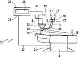
- FIG. 1is a schematic view of a system, in accordance with the present invention, for positioning the eye of a patient for refractive laser surgery;
- FIG. 2is an exploded view, in partial cross section, of an eye stabilizing element, an alignment device, and a surgical laser unit of the present invention, as seen along the line 2 - 2 in FIG. 1 ;
- FIG. 3is a top view of a plurality of pressure sensors in contact with an alignment device of the present invention, as seen along the line 3 - 3 in FIG. 1 ;
- FIG. 4Ais a representation of a pattern of reflected light indicating a proper engagement between an eye stabilizing element and an alignment device of the present invention.
- FIG. 4Bis a representation of a distorted pattern of reflected light indicating an improper engagement between an eye stabilizing element and an alignment device of the present invention.
- FIG. 1A system in accordance with the present invention is shown in FIG. 1 and is generally designated 10 .
- the system 10includes a stationary surgical laser unit 12 and a platform 14 . More specifically, as disclosed herein, the platform 14 is used for supporting a patient 16 , and positioning an eye 18 of the patient 16 relative to the surgical laser unit 12 during a laser surgery.
- system 10includes an eye stabilizing element 20 which is placed on the eye 18 and an alignment device 22 that is mounted or positioned on the laser unit 12 for engagement with the eye stabilizing element 20 .
- the alignment device 22may be mounted on the surgical laser unit 12 , or the device 22 may be integral to the surgical laser unit 12 .
- the platform 14is a chair that includes a motorized control assembly 24 which can be selectively activated to move and reconfigure the chair 14 .
- the system 10also includes a computer controller 26 which has a graphical user interface 28 for receiving instructions from, and presenting information such as alignment and system functionality data to, a system operator (not shown).
- the computer controller 26is in electronic communication with the motorized control assembly 24 of the chair 14 for directing the movement of the chair 14 , and with the surgical laser unit 12 for controlling the settings, timing and functioning of the unit 12 .
- an electrical cable 30connects the computer controller 26 to the surgical laser unit 12 .
- an electrical cable 32is connected from the computer controller 26 to the motorized control assembly 24 .
- the system 10 of the present inventionincludes a console 34 for housing the computer controller 26 .
- the eye stabilizing element 20 of the present inventionis shown to include a hollow, substantially cylindrical shaped base member 36 which defines a longitudinal axis 38 . More specifically, the base member 36 includes an open first end 40 and an open second end 42 .
- the eye stabilizing element 20also includes a curved lens 44 that is centered on the axis 38 with the periphery 46 of the lens 44 in contact with the first end 40 of the base member 36 .
- the curved lens 44is positioned to create an interior cavity 48 between the lens 44 and the base member 36 .
- the curved lens 44is shaped with a concave contact surface 50 that will substantially conform to the anterior surface 52 of the cornea 54 of the eye 18 .
- the contact surface 50 of lens 44will have a radius of curvature that is greater than 5 mm.
- the radius of curvatureis approximately 8.8 mm.
- the eye stabilizing element 20can be made of any of a type of materials well known in the pertinent art.
- the lens 44must be a clear, transparent material such as Poly(methyl methacrylate), also known as “PMMA”.
- the receptacle 56Extending outwardly from the base member 36 is a hollow receptacle 56 that is attached to the first end 40 of the base member 36 .
- the receptacle 56includes a wall 58 that is symmetrically oriented on the axis 38 to surround the lens 44 and extend axially away from the lens 44 .
- the wall 58is formed with an interior surface 60 that is preferably tapered inwardly, which is to say the diameter of the taper decreases in an axial direction toward the lens 48 .
- the receptacle 56 of the eye stabilizing element 20also includes diametrically opposed tabs 62 a and 62 b that extend radially from the wall 58 of the receptacle 56 for use in engaging the alignment device 22 with the eye stabilizing element 20 .
- the eye stabilizing element 20includes a recessed vacuum channel 64 that is formed at the periphery 46 of the lens 44 . Additionally, an air passage 66 is formed in the wall 58 of the receptacle 56 for fluid communication between the vacuum channel 64 and the tab 62 b . A primary vacuum fitting 68 is in fluid communication with the air passage 66 at the point of termination in the tab 62 b . As shown in FIGS. 1 and 2 , the system 10 also includes a vacuum line 70 that is connected to the vacuum fitting 68 . Additionally, a vacuum pump 72 is in fluid communication with the vacuum line 70 for evacuating the air passage 68 and the vacuum channel 60 . Collectively, the vacuum fitting 68 , line 70 and pump 72 constitute a primary vacuum subsystem 73 .
- the alignment device 22includes a hollow tip member 74 having a first end 76 and a second end 78 .
- both the first end 76 and the second end 78 of the tip member 74are open.
- a wall 79 of the tip member 74extends from the first end 76 toward the second end 78 .
- the wall 79is a conical shaped wall 70 that is tapered with an increasing diameter from the first end 76 toward the second end 78 .
- the outer surface 80 of the tip member 74is dimensioned to precisely mate with the interior surface 60 of the wall 58 of the eye stabilizing element 20 .
- the tip member 74includes a shelf 82 which extends around the periphery of the second end 78 of the tip member 74 .
- the shelf 82may be formed with a circumferential vacuum groove 84 that extends around the periphery of the second end 78 of the tip member 74 and it is dimensioned to abut with the tabs 62 a and 62 b of the eye stabilizing element 20 .
- a secondary vacuum fitting 86is provided for establishing fluid communication with the vacuum groove 84 . More specifically, as shown in FIGS.
- the system 10may include a vacuum line 88 and a vacuum pump 90 for evacuating air from the vacuum groove 84 through the vacuum fitting 86 .
- the vacuum fitting 86 , line 88 and pump 90constitute a secondary vacuum subsystem 91 .
- the alignment device 22may include a mounting ring 92 for connecting the alignment device 22 to the surgical laser unit 12 .
- a mounting ring 92for connecting the alignment device 22 to the surgical laser unit 12 .
- a plurality of extension armsconnected to the mounting ring 92 are a plurality of extension arms, of which 94 a , 94 b , 94 c and 94 d ( FIG. 3 ) are exemplary.
- the extension arms 94 a - dconnect the mounting ring 92 to the second end 78 of the tip member 74 to position the mounting ring 92 at a length “I 1 ” from the tip member 74 .
- the alignment device 22When the alignment device 22 is positioned on the laser unit 12 , the alignment device 22 will contact one or more pressure sensors of which pressure sensors 96 a , 96 b and 96 c are exemplary.
- the pressure sensors 96 a - clie in a plane that is substantially parallel to the plane of the mounting ring 92 . As best seen in FIG. 3 , they are each positioned an equal distance from the center point 98 of the mounting ring 92 .
- the position of the pressure sensors 96 a - crelative to each other. Specifically, the three pressure sensors 96 a - c are equidistant from each other, i.e. positioned 120° apart.
- the preferred embodiment of the present inventionincludes a plurality of light sources mounted on the surgical laser unit 12 , of which light sources 99 a , 99 b , 99 c , 99 d , 99 e (shown in shadow) and 99 f (not shown) are exemplary.
- the light sources 99 a - fare positioned on the surgical laser unit 12 to illuminate the eye 18 during the surgical procedure.
- the patient 16is positioned in the chair 14 and the eye stabilizing element 20 is placed on the eye 18 . More specifically, the contact surface 50 of the lens 44 of the eye stabilizing element 20 interfaces with the anterior surface 52 of the cornea 54 of the eye 18 .
- the computer controller 26then directs the motorized control assembly 24 to move and reconfigure the chair 14 . Specifically, the chair 14 is moved to generally align the eye 18 of the patient 16 with the stationary surgical laser unit 12 .
- the primary vacuum line 70is then connected to the primary vacuum fitting 68 and to the primary vacuum pump 72 .
- the primary vacuum subsystem 73evacuates air from the vacuum channel 64 through the air passage 66 .
- the evacuation of the vacuum channel 64creates a suction force at the interface of the contact surface 50 and the anterior surface 52 of the cornea 54 . Further, the force induced by the suction (a relative vacuum in the range of approximately 150-600 mbar) draws and holds the anterior surface 52 of the cornea 54 against the contact surface 50 of the lens 44 . Consequently, the eye stabilizing element 20 is held immovable against the eye 18 . If for any reason the eye stabilizing element 20 is not properly seated on the eye 18 , the partial vacuum will not form. In this case, an error message is displayed for the system operator on the graphical user interface 28 of the computer controller 26 . Of note, the error message may be either a visual or an audio message.
- the alignment device 22is mounted, as necessary, on the surgical laser unit 12 .
- the mounting ring 92is secured to the surgical laser unit 12 .
- the mounting ring 92 of the alignment device 22contacts, and exerts a pressure against, the pressure sensors 96 a - c .
- data from the pressure sensors 96 a - cis communicated to the computer controller 26 via the electrical cable 30 .
- the chair 14is moved through a “docking” procedure whereby the eye stabilizing element 20 is moved to engage with the alignment device 22 .
- the outer surface 80 of the hollow tip member 74 of the alignment device 22is engaged by the interior surface 60 of the wall 58 of the eye stabilizing element 20 .
- the interior surface 60 of the wall 58is dimensioned to precisely match the dimensions of the outer surface 80 of the tip member 74 .
- the tabs 62 a and 62 b of the eye stabilizing element 20mate with the shelf 82 of the alignment device 22 .
- the interactive forces that are generated between the eye stabilizing element 20 and the alignment device 22are monitored by the pressure sensors 96 a - c .
- the force magnitudes experienced by the pressure sensors 96 a - ccan be used to determine the magnitude and direction of the forces exerted against the eye 18 during the docking procedure.
- the operation of the system 10is monitored to ensure patient 16 safety, and to minimize the risk of unwanted damage to the eye 18 .
- a predetermined force thresholdis reached, either in the direction or the magnitude of the forces exerted on the eye 18 , further movement of the patient 16 toward the surgical laser unit 12 is prevented by the computer controller 26 .
- the threshold force valuesare reached, the chair 14 and the patient 16 can only be moved in a direction away from the surgical laser unit 12 .
- the eye stabilizing element 20 of the present inventionWhen the eye stabilizing element 20 of the present invention is properly engaged with the alignment device 22 , the eye 18 is aligned with the surgical laser unit 12 . In addition, the eye 18 will be positioned at a known distance from the surgical laser unit 12 . More specifically, the extension arms 94 a - d establish a fixed distance “I 1 ” between the mounting ring 92 and the second end 78 of the tip member 74 . Further, the height “h 1 ” of the tip member 74 is known and fixed as well. Thus, when the eye stabilizing element 20 is engaged with the alignment device 22 , the lens 44 and cornea 54 are a known distance from the surgical laser unit 12 , more specifically, a known distance from the cutting lenses (not shown) of the surgical laser unit 12 .
- the eye stabilizing element 20 , the alignment device 22 and the cutting lensesmay be concertedly moved axially relative to the longitudinal axis 38 formed by the eye stabilizing element 20 .
- the distance between the lens 44 of the eye stabilizing element 20 and the cutting lenses of the surgical laser unit 12remains fixed, regardless of the concerted movement of the eye stabilizing element 20 , the alignment device 22 and the cutting lenses.
- An important aspect of the present inventionis to maintain this fixed spatial relationship between the eye 18 and the surgical laser unit 12 during the course of the laser surgery. Consequently, the contact between the alignment device 22 and the eye stabilizing element 20 must be maintained.
- the secondary vacuum subsystem 91is activated. Specifically, the secondary vacuum line 88 is connected to the secondary vacuum fitting 86 and the secondary vacuum pump 90 . Thereafter, the secondary vacuum pump 90 is used to evacuate the vacuum groove 84 . The evacuation of the vacuum groove 84 creates a suction whereby the eye stabilizing element 20 is drawn against the alignment device 22 .
- the interactive force that maintains the engagementis a minimal force, which is to say it can be overcome by a moderate force in the opposite direction.
- the alignment device 22 and the eye stabilizing element 20may be disengaged without injuring the patient 16 .
- the plurality of light sources 99 a - f that are mounted on the surgical laser unit 12may be used to help verify a proper engagement. Specifically, it happens that in addition to illuminating the eye 18 , the light sources 99 a - f also create a circular pattern of reflected light that is observable by the system operator. Referring now to FIG. 4A , an exemplary pattern of reflected light 100 is shown. Importantly, when the pattern of reflected light 100 is circular, the eye stabilizing element 20 is properly engaged and aligned with the alignment device 22 .
- the pattern of reflected light 100will be displaced or distorted from its preferred orientation. In this situation, as shown in FIG. 4B , the pattern of light 102 is indicative of an improper engagement. Further, the system operator can observe the misaligned pattern of reflected light on the graphical user interface 28 , and terminate the surgical procedure until such time as a proper engagement between the eye stabilizing element 20 and the alignment device 22 can be achieved. Once proper engagement is achieved, the laser surgery procedure may continue.
- the surgical laser unit 12During a laser surgery procedure, the surgical laser unit 12 generates a laser beam that travels along a beam path that is substantially coincident with the center point 98 of the mounting ring 92 .
- the laser beamthen passes on the beam path substantially along the longitudinal axis 38 of the base member 36 , and the optical axis 104 of the eye 18 .
- the laser beamexits the surgical laser unit 12 , it thereafter travels through both the alignment device 22 , and its hollow tip member 74 .
- the laser beamAfter transiting the tip member 74 , the laser beam is incident on the contact lens 44 of the eye stabilizing element 20 at or near the apex 106 of the curved lens 44 .
- the laser beamthen travels through the clear, plastic contact lens 44 , and enters the cornea 54 of the eye 18 to accomplish the laser surgery.
Landscapes
- Health & Medical Sciences (AREA)
- Ophthalmology & Optometry (AREA)
- Optics & Photonics (AREA)
- Physics & Mathematics (AREA)
- Heart & Thoracic Surgery (AREA)
- Surgery (AREA)
- Engineering & Computer Science (AREA)
- Biomedical Technology (AREA)
- Nuclear Medicine, Radiotherapy & Molecular Imaging (AREA)
- Vascular Medicine (AREA)
- Life Sciences & Earth Sciences (AREA)
- Animal Behavior & Ethology (AREA)
- General Health & Medical Sciences (AREA)
- Public Health (AREA)
- Veterinary Medicine (AREA)
- Eye Examination Apparatus (AREA)
- Laser Surgery Devices (AREA)
Abstract
Description
Claims (15)
Priority Applications (5)
| Application Number | Priority Date | Filing Date | Title |
|---|---|---|---|
| US10/790,625US7402159B2 (en) | 2004-03-01 | 2004-03-01 | System and method for positioning a patient for laser surgery |
| JP2004352371AJP4224018B2 (en) | 2004-03-01 | 2004-12-06 | System for positioning a patient for laser surgery |
| EP05075113.0AEP1570822B1 (en) | 2004-03-01 | 2005-01-17 | System for positioning a patient for laser surgery |
| EP13163811.6AEP2617399A1 (en) | 2004-03-01 | 2005-01-17 | System for positioning a patient for laser surgery |
| ES05075113.0TES2450647T3 (en) | 2004-03-01 | 2005-01-17 | System to place a patient for laser surgery |
Applications Claiming Priority (1)
| Application Number | Priority Date | Filing Date | Title |
|---|---|---|---|
| US10/790,625US7402159B2 (en) | 2004-03-01 | 2004-03-01 | System and method for positioning a patient for laser surgery |
Publications (2)
| Publication Number | Publication Date |
|---|---|
| US20050192562A1 US20050192562A1 (en) | 2005-09-01 |
| US7402159B2true US7402159B2 (en) | 2008-07-22 |
Family
ID=34750576
Family Applications (1)
| Application Number | Title | Priority Date | Filing Date |
|---|---|---|---|
| US10/790,625Active2026-06-15US7402159B2 (en) | 2004-03-01 | 2004-03-01 | System and method for positioning a patient for laser surgery |
Country Status (4)
| Country | Link |
|---|---|
| US (1) | US7402159B2 (en) |
| EP (2) | EP2617399A1 (en) |
| JP (1) | JP4224018B2 (en) |
| ES (1) | ES2450647T3 (en) |
Cited By (51)
| Publication number | Priority date | Publication date | Assignee | Title |
|---|---|---|---|---|
| US20070185475A1 (en)* | 2006-01-20 | 2007-08-09 | Frey Rudolph W | System and method for providing the shaped structural weakening of the human lens with a laser |
| US20070225693A1 (en)* | 2006-03-10 | 2007-09-27 | Dirk Muehlhoff | Treatment and diagnostic systems for the eye |
| US20080058777A1 (en)* | 2006-09-05 | 2008-03-06 | Intralase Corp. | System and method for resecting corneal tissue using non-continuous initial incisions |
| US20080078752A1 (en)* | 2006-09-29 | 2008-04-03 | Carl Zeiss Meditec Ag | Apparatus and method for material processing using a transparent contact element |
| US20090069794A1 (en)* | 2007-09-10 | 2009-03-12 | Kurtz Ronald M | Apparatus, Systems And Techniques For Interfacing With An Eye In Laser Surgery |
| US20090131921A1 (en)* | 2007-09-06 | 2009-05-21 | Lensx Lasers, Inc. | Precise Targeting of Surgical Photodisruption |
| US20090137991A1 (en)* | 2007-09-18 | 2009-05-28 | Kurtz Ronald M | Methods and Apparatus for Laser Treatment of the Crystalline Lens |
| US20090137993A1 (en)* | 2007-09-18 | 2009-05-28 | Kurtz Ronald M | Methods and Apparatus for Integrated Cataract Surgery |
| US20090137988A1 (en)* | 2007-11-02 | 2009-05-28 | Lensx Lasers, Inc | Methods And Apparatus For Improved Post-Operative Ocular Optical Performance |
| US20090143772A1 (en)* | 2007-09-05 | 2009-06-04 | Kurtz Ronald M | Laser-Induced Protection Shield in Laser Surgery |
| US20090149841A1 (en)* | 2007-09-10 | 2009-06-11 | Kurtz Ronald M | Effective Laser Photodisruptive Surgery in a Gravity Field |
| US20090149840A1 (en)* | 2007-09-06 | 2009-06-11 | Kurtz Ronald M | Photodisruptive Treatment of Crystalline Lens |
| US20090171327A1 (en)* | 2007-09-06 | 2009-07-02 | Lensx Lasers, Inc. | Photodisruptive Laser Treatment of the Crystalline Lens |
| US20090177189A1 (en)* | 2008-01-09 | 2009-07-09 | Ferenc Raksi | Photodisruptive laser fragmentation of tissue |
| WO2011094678A1 (en)* | 2010-02-01 | 2011-08-04 | Lensar, Inc. | Purkinjie image-based alignment of suction ring in ophthalmic applications |
| US20110194743A1 (en)* | 2010-02-05 | 2011-08-11 | Ferenc Raksi | Gradient Search Integrated with Local Imaging in Laser Surgical Systems |
| US20110202044A1 (en)* | 2010-02-18 | 2011-08-18 | Ilya Goldshleger | Optical Coherence Tomographic System for Ophthalmic Surgery |
| US20120240939A1 (en)* | 2011-03-24 | 2012-09-27 | Jochen Kandulla | Apparatus and Method for Control of Refractive Index Changes in a Material |
| US8382745B2 (en) | 2009-07-24 | 2013-02-26 | Lensar, Inc. | Laser system and method for astigmatic corrections in association with cataract treatment |
| US8398238B1 (en) | 2011-08-26 | 2013-03-19 | Alcon Lensx, Inc. | Imaging-based guidance system for ophthalmic docking using a location-orientation analysis |
| US8398236B2 (en) | 2010-06-14 | 2013-03-19 | Alcon Lensx, Inc. | Image-guided docking for ophthalmic surgical systems |
| US8459794B2 (en) | 2011-05-02 | 2013-06-11 | Alcon Lensx, Inc. | Image-processor-controlled misalignment-reduction for ophthalmic systems |
| US8465478B2 (en) | 2009-07-24 | 2013-06-18 | Lensar, Inc. | System and method for performing LADAR assisted procedures on the lens of an eye |
| US8480659B2 (en) | 2008-07-25 | 2013-07-09 | Lensar, Inc. | Method and system for removal and replacement of lens material from the lens of an eye |
| US8500723B2 (en) | 2008-07-25 | 2013-08-06 | Lensar, Inc. | Liquid filled index matching device for ophthalmic laser procedures |
| USD694890S1 (en) | 2010-10-15 | 2013-12-03 | Lensar, Inc. | Laser system for treatment of the eye |
| USD695408S1 (en) | 2010-10-15 | 2013-12-10 | Lensar, Inc. | Laser system for treatment of the eye |
| US8617146B2 (en) | 2009-07-24 | 2013-12-31 | Lensar, Inc. | Laser system and method for correction of induced astigmatism |
| US20140128852A1 (en)* | 2012-11-02 | 2014-05-08 | Optimedica Corporation | Interface force feedback in a laser eye surgery system |
| US8758332B2 (en) | 2009-07-24 | 2014-06-24 | Lensar, Inc. | Laser system and method for performing and sealing corneal incisions in the eye |
| US8801186B2 (en) | 2010-10-15 | 2014-08-12 | Lensar, Inc. | System and method of scan controlled illumination of structures within an eye |
| US8845624B2 (en) | 2010-06-25 | 2014-09-30 | Alcon LexSx, Inc. | Adaptive patient interface |
| US8939967B2 (en) | 2011-08-03 | 2015-01-27 | Alcon Lensx, Inc. | Patient interface defogger |
| US8981914B1 (en) | 2010-09-27 | 2015-03-17 | University of Pittsburgh—of the Commonwealth System of Higher Education | Portable haptic force magnifier |
| US9023016B2 (en) | 2011-12-19 | 2015-05-05 | Alcon Lensx, Inc. | Image processor for intra-surgical optical coherence tomographic imaging of laser cataract procedures |
| US9044304B2 (en) | 2011-12-23 | 2015-06-02 | Alcon Lensx, Inc. | Patient interface with variable applanation |
| US9066784B2 (en) | 2011-12-19 | 2015-06-30 | Alcon Lensx, Inc. | Intra-surgical optical coherence tomographic imaging of cataract procedures |
| US9089401B2 (en) | 2011-05-06 | 2015-07-28 | Alcon Lensx, Inc. | Adjusting ophthalmic docking system |
| US9180051B2 (en) | 2006-01-20 | 2015-11-10 | Lensar Inc. | System and apparatus for treating the lens of an eye |
| US9375349B2 (en) | 2006-01-20 | 2016-06-28 | Lensar, Llc | System and method for providing laser shot patterns to the lens of an eye |
| US9398979B2 (en) | 2013-03-11 | 2016-07-26 | Technolas Perfect Vision Gmbh | Dimensional compensator for use with a patient interface |
| US9492322B2 (en) | 2009-11-16 | 2016-11-15 | Alcon Lensx, Inc. | Imaging surgical target tissue by nonlinear scanning |
| US9532708B2 (en) | 2010-09-17 | 2017-01-03 | Alcon Lensx, Inc. | Electronically controlled fixation light for ophthalmic imaging systems |
| US9545338B2 (en) | 2006-01-20 | 2017-01-17 | Lensar, Llc. | System and method for improving the accommodative amplitude and increasing the refractive power of the human lens with a laser |
| US9603744B2 (en) | 2012-11-09 | 2017-03-28 | Technolas Perfect Vision Gmbh | Adaptable patient interface |
| US9622913B2 (en) | 2011-05-18 | 2017-04-18 | Alcon Lensx, Inc. | Imaging-controlled laser surgical system |
| US9889043B2 (en) | 2006-01-20 | 2018-02-13 | Lensar, Inc. | System and apparatus for delivering a laser beam to the lens of an eye |
| US10219948B2 (en) | 2016-02-24 | 2019-03-05 | Perfect Ip, Llc | Ophthalmic laser treatment system and method |
| US10335315B2 (en) | 2013-02-01 | 2019-07-02 | Alcon Lensx, Inc. | Bi-radial patient interface |
| US10463541B2 (en) | 2011-03-25 | 2019-11-05 | Lensar, Inc. | System and method for correcting astigmatism using multiple paired arcuate laser generated corneal incisions |
| EP3923779A4 (en)* | 2019-02-15 | 2022-11-09 | AMO Development, LLC | INTRAOCULAR PRESSURE MEASUREMENT FOR AN EYE DOCKED TO A LASER SYSTEM |
Families Citing this family (40)
| Publication number | Priority date | Publication date | Assignee | Title |
|---|---|---|---|---|
| US20080071254A1 (en)* | 2001-01-29 | 2008-03-20 | Advanced Medical Optics, Inc. | Ophthalmic interface apparatus and system and method of interfacing a surgical laser with an eye |
| US20120016349A1 (en) | 2001-01-29 | 2012-01-19 | Amo Development, Llc. | Hybrid ophthalmic interface apparatus and method of interfacing a surgical laser with an eye |
| US20060020259A1 (en)* | 2004-07-20 | 2006-01-26 | Klaus Baumeister | System for performing a corneal transplantation |
| DE102005001249A1 (en)* | 2005-01-11 | 2006-07-20 | Carl Zeiss Meditec Ag | Safety mechanism for a laser treatment device |
| US7390089B2 (en)* | 2005-02-25 | 2008-06-24 | 20/10 Perfect Vision Optische Geraete Gmbh | Device and method for aligning an eye with a surgical laser |
| US7955324B2 (en)* | 2005-10-21 | 2011-06-07 | Technolas Perfect Vision Gmbh | Cornea contact system |
| US7611507B2 (en)* | 2005-10-24 | 2009-11-03 | Amo Development Llc | Disposable patient interface |
| US20070173791A1 (en)* | 2006-01-20 | 2007-07-26 | Intralase Corp. | System for ophthalmic laser surgery |
| US20070173796A1 (en)* | 2006-01-25 | 2007-07-26 | Ralf Kessler | Device and method for calibrating a laser system |
| US8182471B2 (en) | 2006-03-17 | 2012-05-22 | Amo Manufacturing Usa, Llc. | Intrastromal refractive correction systems and methods |
| US8382744B2 (en)* | 2006-08-23 | 2013-02-26 | Szymon Suckewer | Method and device for cornea reshaping by intrastromal tissue removal |
| US7535991B2 (en) | 2006-10-16 | 2009-05-19 | Oraya Therapeutics, Inc. | Portable orthovoltage radiotherapy |
| US7620147B2 (en) | 2006-12-13 | 2009-11-17 | Oraya Therapeutics, Inc. | Orthovoltage radiotherapy |
| US20080218692A1 (en)* | 2007-03-06 | 2008-09-11 | Hopler Mark D | Reflectometry/Interferometry System and Method for Corneal Plane Positioning |
| EP2133048B1 (en) | 2007-03-14 | 2019-03-13 | WaveLight GmbH | Apparatus for connecting an element to an eye |
| US8506558B2 (en) | 2008-01-11 | 2013-08-13 | Oraya Therapeutics, Inc. | System and method for performing an ocular irradiation procedure |
| US8363783B2 (en) | 2007-06-04 | 2013-01-29 | Oraya Therapeutics, Inc. | Method and device for ocular alignment and coupling of ocular structures |
| US20100324543A1 (en)* | 2007-09-18 | 2010-12-23 | Kurtz Ronald M | Method And Apparatus For Integrating Cataract Surgery With Glaucoma Or Astigmatism Surgery |
| US20100324542A1 (en)* | 2007-11-02 | 2010-12-23 | Kurtz Ronald M | Method to Guide a Cataract Procedure by Corneal Imaging |
| US8632526B2 (en)* | 2007-11-07 | 2014-01-21 | Amo Development, Llc | System and method of interfacing a surgical laser with an eye |
| US7801271B2 (en) | 2007-12-23 | 2010-09-21 | Oraya Therapeutics, Inc. | Methods and devices for orthovoltage ocular radiotherapy and treatment planning |
| EP3272395B1 (en) | 2007-12-23 | 2019-07-17 | Carl Zeiss Meditec, Inc. | Devices for detecting, controlling, and predicting radiation delivery |
| MX2011002070A (en)* | 2008-08-25 | 2011-06-21 | Wavelight Gmbh | Coupling of an eye to a laser device. |
| US8852175B2 (en) | 2008-11-21 | 2014-10-07 | Amo Development Llc | Apparatus, system and method for precision depth measurement |
| US9974690B2 (en) | 2009-03-23 | 2018-05-22 | Wavelight Gmbh | Apparatus and method for LASIK |
| US10624787B2 (en) | 2009-07-10 | 2020-04-21 | Alcon Inc. | Apparatus for cutting a tissue section of an eye by laser radiation |
| WO2011038748A1 (en)* | 2009-09-30 | 2011-04-07 | Wavelight Gmbh | Device for ophthalmological laser surgery |
| DE102010004696B4 (en) | 2010-01-15 | 2022-04-28 | Schwind Eye-Tech-Solutions Gmbh | Device for treating a patient's eye with laser radiation and method for positioning |
| US9629750B2 (en)* | 2012-04-18 | 2017-04-25 | Technolas Perfect Vision Gmbh | Surgical laser unit with variable modes of operation |
| US10285860B2 (en)* | 2012-11-02 | 2019-05-14 | Optimedica Corporation | Vacuum loss detection during laser eye surgery |
| US9987165B2 (en) | 2012-11-02 | 2018-06-05 | Optimedica Corporation | Liquid optical interface for laser eye surgery system |
| AU2012396954B2 (en)* | 2012-12-20 | 2016-09-01 | Alcon Inc. | Apparatus, interface unit, suction ring and method to monitor corneal tissue |
| DE102015013237A1 (en)* | 2015-10-12 | 2017-04-13 | Novartis Ag | Centering technique for a cutting laser for refractive eye surgery |
| PL3167853T3 (en)* | 2015-11-10 | 2018-08-31 | Novartis Ag | Modular patient adapter for an eye laser device |
| US10799394B2 (en) | 2016-04-05 | 2020-10-13 | Amo Development, Llc | Patient interface device for laser eye surgery having light guiding structure for illuminating eye |
| ES3010396T3 (en)* | 2016-11-03 | 2025-04-02 | Alcon Inc | System and method for indirectly determining weight on eye during laser ophthalmic surgery |
| US10973688B2 (en)* | 2019-03-15 | 2021-04-13 | Amo Development, Llc | Eye suction loss and corneal applanation detection in ophthalmic docking system using optical signal |
| TWI784423B (en)* | 2021-02-26 | 2022-11-21 | 艾克夏醫療儀器股份有限公司 | Eye-abutting system of femtosecond laser ophthalmic equipment and eye-abutting base as well as eye-abutting ring mounted thereon |
| TWI784490B (en)* | 2021-04-21 | 2022-11-21 | 艾克夏醫療儀器股份有限公司 | Eye docking system for excimer laser ophthalmological apparatus and docking piece for said eye docking system |
| CN115337142A (en)* | 2022-10-13 | 2022-11-15 | 广东麦特维逊医学研究发展有限公司 | Eye negative pressure control and monitoring system and method thereof |
Citations (29)
| Publication number | Priority date | Publication date | Assignee | Title |
|---|---|---|---|---|
| US4391275A (en) | 1979-11-28 | 1983-07-05 | Lasag Ag | Method for the surgical treatment of the eye |
| US4443075A (en) | 1981-06-26 | 1984-04-17 | Sri International | Stabilized visual system |
| US4503854A (en) | 1983-06-16 | 1985-03-12 | Jako Geza J | Laser surgery |
| US4517980A (en) | 1981-10-02 | 1985-05-21 | Essilor International Cie Generale D'optique | Ophthalmic surgical laser apparatus |
| US4579430A (en) | 1982-12-11 | 1986-04-01 | Carl-Zeiss-Stiftung | Method and apparatus for forming an image of the ocular fundus |
| US4702575A (en) | 1981-05-11 | 1987-10-27 | The United States Of America As Represented By The Secretary Of The Navy | Helmet mounted eye tracker using a position sensing detector |
| US4718418A (en)* | 1983-11-17 | 1988-01-12 | Lri L.P. | Apparatus for ophthalmological surgery |
| US4848340A (en) | 1988-02-10 | 1989-07-18 | Intelligent Surgical Lasers | Eyetracker and method of use |
| US4903695A (en) | 1988-11-30 | 1990-02-27 | Lri L.P. | Method and apparatus for performing a keratomileusis or the like operation |
| US4905711A (en) | 1988-03-08 | 1990-03-06 | Taunton Technologies, Inc. | Eye restraining device |
| US4994058A (en) | 1986-03-19 | 1991-02-19 | Summit Technology, Inc. | Surface shaping using lasers |
| US5108412A (en) | 1988-11-11 | 1992-04-28 | Jorg H. Krumeich | Suction ring for surgical operations on the human eye |
| US5226903A (en) | 1991-01-30 | 1993-07-13 | Nidek Co., Ltd. | Apparatus for ophthalmic operation using photocoagulation by a laser beam |
| US5336215A (en) | 1993-01-22 | 1994-08-09 | Intelligent Surgical Lasers | Eye stabilizing mechanism for use in ophthalmic laser surgery |
| US5490849A (en)* | 1990-07-13 | 1996-02-13 | Smith; Robert F. | Uniform-radiation caustic surface for photoablation |
| US5549632A (en)* | 1992-10-26 | 1996-08-27 | Novatec Laser Systems, Inc. | Method and apparatus for ophthalmic surgery |
| US5787890A (en) | 1991-12-16 | 1998-08-04 | Laser Diagnostic Technologies, Inc. | Eye examination apparatus employing polarized light probe |
| US5807380A (en)* | 1996-04-26 | 1998-09-15 | Dishler; Jon G. | Optical guide and method for use in corrective laser eye surgery |
| US6099522A (en)* | 1989-02-06 | 2000-08-08 | Visx Inc. | Automated laser workstation for high precision surgical and industrial interventions |
| US6254595B1 (en)* | 1998-10-15 | 2001-07-03 | Intralase Corporation | Corneal aplanation device |
| US6373571B1 (en)* | 1999-03-11 | 2002-04-16 | Intralase Corp. | Disposable contact lens for use with an ophthalmic laser system |
| US6406473B1 (en)* | 1999-10-01 | 2002-06-18 | Visx, Incorporated | Patient fixation system and method for laser eye surgery |
| US6562026B2 (en)* | 1998-06-26 | 2003-05-13 | Visx, Incorporated | Surgical laser system microscope with separated ocular and objective lenses |
| US6656197B1 (en)* | 2001-06-28 | 2003-12-02 | Lahaye Leon C. | Multi-function surgical instrument for facilitating ophthalmic laser surgery |
| US6730074B2 (en)* | 2002-05-24 | 2004-05-04 | 20/10 Perfect Vision Optische Geraete Gmbh | Cornea contact system for laser surgery |
| US6964659B2 (en)* | 2002-05-30 | 2005-11-15 | Visx, Incorporated | Thermal modeling for reduction of refractive laser surgery times |
| US20060020259A1 (en)* | 2004-07-20 | 2006-01-26 | Klaus Baumeister | System for performing a corneal transplantation |
| US7018376B2 (en)* | 2001-01-29 | 2006-03-28 | Intralase Corp. | Ocular fixation and stabilization device for ophthalmic surgical applications |
| US20060192921A1 (en)* | 2005-02-25 | 2006-08-31 | Frieder Loesel | Device and method for aligning an eye with a surgical laser |
Family Cites Families (4)
| Publication number | Priority date | Publication date | Assignee | Title |
|---|---|---|---|---|
| DE19831674A1 (en)* | 1998-07-15 | 2000-01-20 | Laserforum Gmbh Forum Fuer Las | Device to fix eyes in refractive surgical laser operations |
| US6899707B2 (en)* | 2001-01-29 | 2005-05-31 | Intralase Corp. | Applanation lens and method for ophthalmic surgical applications |
| US6610051B2 (en) | 2001-10-12 | 2003-08-26 | 20/10 Perfect Vision Optische Geraete Gmbh | Device and method for performing refractive surgery |
| DE10354025B4 (en)* | 2003-11-19 | 2022-03-24 | Carl Zeiss Meditec Ag | Adapter for mechanically coupling a laser processing device to an object |
- 2004
- 2004-03-01USUS10/790,625patent/US7402159B2/enactiveActive
- 2004-12-06JPJP2004352371Apatent/JP4224018B2/ennot_activeExpired - Lifetime
- 2005
- 2005-01-17EPEP13163811.6Apatent/EP2617399A1/ennot_activeWithdrawn
- 2005-01-17EPEP05075113.0Apatent/EP1570822B1/ennot_activeExpired - Lifetime
- 2005-01-17ESES05075113.0Tpatent/ES2450647T3/ennot_activeExpired - Lifetime
Patent Citations (30)
| Publication number | Priority date | Publication date | Assignee | Title |
|---|---|---|---|---|
| US4391275A (en) | 1979-11-28 | 1983-07-05 | Lasag Ag | Method for the surgical treatment of the eye |
| US4702575A (en) | 1981-05-11 | 1987-10-27 | The United States Of America As Represented By The Secretary Of The Navy | Helmet mounted eye tracker using a position sensing detector |
| US4443075A (en) | 1981-06-26 | 1984-04-17 | Sri International | Stabilized visual system |
| US4517980A (en) | 1981-10-02 | 1985-05-21 | Essilor International Cie Generale D'optique | Ophthalmic surgical laser apparatus |
| US4579430A (en) | 1982-12-11 | 1986-04-01 | Carl-Zeiss-Stiftung | Method and apparatus for forming an image of the ocular fundus |
| US4503854A (en) | 1983-06-16 | 1985-03-12 | Jako Geza J | Laser surgery |
| US4718418A (en)* | 1983-11-17 | 1988-01-12 | Lri L.P. | Apparatus for ophthalmological surgery |
| US4994058A (en) | 1986-03-19 | 1991-02-19 | Summit Technology, Inc. | Surface shaping using lasers |
| US4848340A (en) | 1988-02-10 | 1989-07-18 | Intelligent Surgical Lasers | Eyetracker and method of use |
| US4905711A (en) | 1988-03-08 | 1990-03-06 | Taunton Technologies, Inc. | Eye restraining device |
| US5108412A (en) | 1988-11-11 | 1992-04-28 | Jorg H. Krumeich | Suction ring for surgical operations on the human eye |
| US4903695A (en) | 1988-11-30 | 1990-02-27 | Lri L.P. | Method and apparatus for performing a keratomileusis or the like operation |
| US4903695C1 (en) | 1988-11-30 | 2001-09-11 | Lri L P | Method and apparatus for performing a keratomileusis or the like operation |
| US6099522A (en)* | 1989-02-06 | 2000-08-08 | Visx Inc. | Automated laser workstation for high precision surgical and industrial interventions |
| US5490849A (en)* | 1990-07-13 | 1996-02-13 | Smith; Robert F. | Uniform-radiation caustic surface for photoablation |
| US5226903A (en) | 1991-01-30 | 1993-07-13 | Nidek Co., Ltd. | Apparatus for ophthalmic operation using photocoagulation by a laser beam |
| US5787890A (en) | 1991-12-16 | 1998-08-04 | Laser Diagnostic Technologies, Inc. | Eye examination apparatus employing polarized light probe |
| US5549632A (en)* | 1992-10-26 | 1996-08-27 | Novatec Laser Systems, Inc. | Method and apparatus for ophthalmic surgery |
| US5336215A (en) | 1993-01-22 | 1994-08-09 | Intelligent Surgical Lasers | Eye stabilizing mechanism for use in ophthalmic laser surgery |
| US5807380A (en)* | 1996-04-26 | 1998-09-15 | Dishler; Jon G. | Optical guide and method for use in corrective laser eye surgery |
| US6562026B2 (en)* | 1998-06-26 | 2003-05-13 | Visx, Incorporated | Surgical laser system microscope with separated ocular and objective lenses |
| US6254595B1 (en)* | 1998-10-15 | 2001-07-03 | Intralase Corporation | Corneal aplanation device |
| US6373571B1 (en)* | 1999-03-11 | 2002-04-16 | Intralase Corp. | Disposable contact lens for use with an ophthalmic laser system |
| US6406473B1 (en)* | 1999-10-01 | 2002-06-18 | Visx, Incorporated | Patient fixation system and method for laser eye surgery |
| US7018376B2 (en)* | 2001-01-29 | 2006-03-28 | Intralase Corp. | Ocular fixation and stabilization device for ophthalmic surgical applications |
| US6656197B1 (en)* | 2001-06-28 | 2003-12-02 | Lahaye Leon C. | Multi-function surgical instrument for facilitating ophthalmic laser surgery |
| US6730074B2 (en)* | 2002-05-24 | 2004-05-04 | 20/10 Perfect Vision Optische Geraete Gmbh | Cornea contact system for laser surgery |
| US6964659B2 (en)* | 2002-05-30 | 2005-11-15 | Visx, Incorporated | Thermal modeling for reduction of refractive laser surgery times |
| US20060020259A1 (en)* | 2004-07-20 | 2006-01-26 | Klaus Baumeister | System for performing a corneal transplantation |
| US20060192921A1 (en)* | 2005-02-25 | 2006-08-31 | Frieder Loesel | Device and method for aligning an eye with a surgical laser |
Cited By (78)
| Publication number | Priority date | Publication date | Assignee | Title |
|---|---|---|---|---|
| US9375349B2 (en) | 2006-01-20 | 2016-06-28 | Lensar, Llc | System and method for providing laser shot patterns to the lens of an eye |
| US9180051B2 (en) | 2006-01-20 | 2015-11-10 | Lensar Inc. | System and apparatus for treating the lens of an eye |
| US10842675B2 (en) | 2006-01-20 | 2020-11-24 | Lensar, Inc. | System and method for treating the structure of the human lens with a laser |
| US8262646B2 (en) | 2006-01-20 | 2012-09-11 | Lensar, Inc. | System and method for providing the shaped structural weakening of the human lens with a laser |
| US20070185475A1 (en)* | 2006-01-20 | 2007-08-09 | Frey Rudolph W | System and method for providing the shaped structural weakening of the human lens with a laser |
| US9545338B2 (en) | 2006-01-20 | 2017-01-17 | Lensar, Llc. | System and method for improving the accommodative amplitude and increasing the refractive power of the human lens with a laser |
| US9889043B2 (en) | 2006-01-20 | 2018-02-13 | Lensar, Inc. | System and apparatus for delivering a laser beam to the lens of an eye |
| US20070225693A1 (en)* | 2006-03-10 | 2007-09-27 | Dirk Muehlhoff | Treatment and diagnostic systems for the eye |
| US7887532B2 (en)* | 2006-09-05 | 2011-02-15 | Amo Development, Llc. | System and method for resecting corneal tissue using non-continuous initial incisions |
| US20080058777A1 (en)* | 2006-09-05 | 2008-03-06 | Intralase Corp. | System and method for resecting corneal tissue using non-continuous initial incisions |
| US9296069B2 (en) | 2006-09-29 | 2016-03-29 | Carl Zeiss Meditec Ag | Apparatus and method for material processing using a transparent contact element |
| US20080078752A1 (en)* | 2006-09-29 | 2008-04-03 | Carl Zeiss Meditec Ag | Apparatus and method for material processing using a transparent contact element |
| US8502113B2 (en) | 2006-09-29 | 2013-08-06 | Carl Zeiss Meditec Ag | Apparatus and method for material processing using a transparent contact element |
| US7863543B2 (en)* | 2006-09-29 | 2011-01-04 | Carl Zeiss Meditec Ag | Apparatus and method for material processing using a transparent contact element |
| US20110102810A1 (en)* | 2006-09-29 | 2011-05-05 | Carl Zeiss Meditec Ag | Apparatus and method for material processing using a transparent contact element |
| US10279425B2 (en) | 2006-09-29 | 2019-05-07 | Carl Zeiss Meditec Ag | Apparatus and method for material processing using a transparent contact element |
| US20090143772A1 (en)* | 2007-09-05 | 2009-06-04 | Kurtz Ronald M | Laser-Induced Protection Shield in Laser Surgery |
| US8764736B2 (en) | 2007-09-05 | 2014-07-01 | Alcon Lensx, Inc. | Laser-induced protection shield in laser surgery |
| US9408749B2 (en) | 2007-09-06 | 2016-08-09 | Alcon Lensx, Inc. | Precise targeting of surgical photodisruption |
| US20090149840A1 (en)* | 2007-09-06 | 2009-06-11 | Kurtz Ronald M | Photodisruptive Treatment of Crystalline Lens |
| US20090131921A1 (en)* | 2007-09-06 | 2009-05-21 | Lensx Lasers, Inc. | Precise Targeting of Surgical Photodisruption |
| US9456925B2 (en) | 2007-09-06 | 2016-10-04 | Alcon Lensx, Inc. | Photodisruptive laser treatment of the crystalline lens |
| US8764737B2 (en) | 2007-09-06 | 2014-07-01 | Alcon Lensx, Inc. | Precise targeting of surgical photodisruption |
| US9044303B2 (en) | 2007-09-06 | 2015-06-02 | Alcon Lensx, Inc. | Precise targeting of surgical photodisruption |
| US20090171327A1 (en)* | 2007-09-06 | 2009-07-02 | Lensx Lasers, Inc. | Photodisruptive Laser Treatment of the Crystalline Lens |
| US9504609B2 (en) | 2007-09-10 | 2016-11-29 | Alcon Lensx, Inc. | Apparatus, systems and techniques for interfacing with an eye in laser surgery |
| US20090149841A1 (en)* | 2007-09-10 | 2009-06-11 | Kurtz Ronald M | Effective Laser Photodisruptive Surgery in a Gravity Field |
| US20090069794A1 (en)* | 2007-09-10 | 2009-03-12 | Kurtz Ronald M | Apparatus, Systems And Techniques For Interfacing With An Eye In Laser Surgery |
| US20090137993A1 (en)* | 2007-09-18 | 2009-05-28 | Kurtz Ronald M | Methods and Apparatus for Integrated Cataract Surgery |
| US20090137991A1 (en)* | 2007-09-18 | 2009-05-28 | Kurtz Ronald M | Methods and Apparatus for Laser Treatment of the Crystalline Lens |
| US20090137988A1 (en)* | 2007-11-02 | 2009-05-28 | Lensx Lasers, Inc | Methods And Apparatus For Improved Post-Operative Ocular Optical Performance |
| US11026838B2 (en) | 2008-01-09 | 2021-06-08 | Alcon Inc. | Photodisruptive laser fragmentation of tissue |
| US9427356B2 (en) | 2008-01-09 | 2016-08-30 | Alcon Lensx, Inc. | Photodisruptive laser fragmentation of tissue |
| US20090177189A1 (en)* | 2008-01-09 | 2009-07-09 | Ferenc Raksi | Photodisruptive laser fragmentation of tissue |
| US8500723B2 (en) | 2008-07-25 | 2013-08-06 | Lensar, Inc. | Liquid filled index matching device for ophthalmic laser procedures |
| US8480659B2 (en) | 2008-07-25 | 2013-07-09 | Lensar, Inc. | Method and system for removal and replacement of lens material from the lens of an eye |
| US8708491B2 (en) | 2008-07-25 | 2014-04-29 | Lensar, Inc. | Method and system for measuring an eye |
| US8758332B2 (en) | 2009-07-24 | 2014-06-24 | Lensar, Inc. | Laser system and method for performing and sealing corneal incisions in the eye |
| US8617146B2 (en) | 2009-07-24 | 2013-12-31 | Lensar, Inc. | Laser system and method for correction of induced astigmatism |
| US8382745B2 (en) | 2009-07-24 | 2013-02-26 | Lensar, Inc. | Laser system and method for astigmatic corrections in association with cataract treatment |
| US8465478B2 (en) | 2009-07-24 | 2013-06-18 | Lensar, Inc. | System and method for performing LADAR assisted procedures on the lens of an eye |
| US9492322B2 (en) | 2009-11-16 | 2016-11-15 | Alcon Lensx, Inc. | Imaging surgical target tissue by nonlinear scanning |
| US8556425B2 (en) | 2010-02-01 | 2013-10-15 | Lensar, Inc. | Purkinjie image-based alignment of suction ring in ophthalmic applications |
| WO2011094678A1 (en)* | 2010-02-01 | 2011-08-04 | Lensar, Inc. | Purkinjie image-based alignment of suction ring in ophthalmic applications |
| US8265364B2 (en) | 2010-02-05 | 2012-09-11 | Alcon Lensx, Inc. | Gradient search integrated with local imaging in laser surgical systems |
| US20110194743A1 (en)* | 2010-02-05 | 2011-08-11 | Ferenc Raksi | Gradient Search Integrated with Local Imaging in Laser Surgical Systems |
| US8414564B2 (en) | 2010-02-18 | 2013-04-09 | Alcon Lensx, Inc. | Optical coherence tomographic system for ophthalmic surgery |
| US20110202044A1 (en)* | 2010-02-18 | 2011-08-18 | Ilya Goldshleger | Optical Coherence Tomographic System for Ophthalmic Surgery |
| US8398236B2 (en) | 2010-06-14 | 2013-03-19 | Alcon Lensx, Inc. | Image-guided docking for ophthalmic surgical systems |
| US8845624B2 (en) | 2010-06-25 | 2014-09-30 | Alcon LexSx, Inc. | Adaptive patient interface |
| US9301878B2 (en) | 2010-06-25 | 2016-04-05 | Alcon Lensx, Inc. | Adaptive patient interface |
| US9532708B2 (en) | 2010-09-17 | 2017-01-03 | Alcon Lensx, Inc. | Electronically controlled fixation light for ophthalmic imaging systems |
| US8981914B1 (en) | 2010-09-27 | 2015-03-17 | University of Pittsburgh—of the Commonwealth System of Higher Education | Portable haptic force magnifier |
| US8801186B2 (en) | 2010-10-15 | 2014-08-12 | Lensar, Inc. | System and method of scan controlled illumination of structures within an eye |
| USD694890S1 (en) | 2010-10-15 | 2013-12-03 | Lensar, Inc. | Laser system for treatment of the eye |
| USD695408S1 (en) | 2010-10-15 | 2013-12-10 | Lensar, Inc. | Laser system for treatment of the eye |
| US20120240939A1 (en)* | 2011-03-24 | 2012-09-27 | Jochen Kandulla | Apparatus and Method for Control of Refractive Index Changes in a Material |
| US10463541B2 (en) | 2011-03-25 | 2019-11-05 | Lensar, Inc. | System and method for correcting astigmatism using multiple paired arcuate laser generated corneal incisions |
| US8459794B2 (en) | 2011-05-02 | 2013-06-11 | Alcon Lensx, Inc. | Image-processor-controlled misalignment-reduction for ophthalmic systems |
| US9089401B2 (en) | 2011-05-06 | 2015-07-28 | Alcon Lensx, Inc. | Adjusting ophthalmic docking system |
| US9622913B2 (en) | 2011-05-18 | 2017-04-18 | Alcon Lensx, Inc. | Imaging-controlled laser surgical system |
| US8939967B2 (en) | 2011-08-03 | 2015-01-27 | Alcon Lensx, Inc. | Patient interface defogger |
| US8398238B1 (en) | 2011-08-26 | 2013-03-19 | Alcon Lensx, Inc. | Imaging-based guidance system for ophthalmic docking using a location-orientation analysis |
| US9066784B2 (en) | 2011-12-19 | 2015-06-30 | Alcon Lensx, Inc. | Intra-surgical optical coherence tomographic imaging of cataract procedures |
| US9456927B2 (en) | 2011-12-19 | 2016-10-04 | Alcon Lensx, Inc. | Image processor for intra-surgical optical coherence tomographic imaging of laser cataract procedures |
| US9456926B2 (en) | 2011-12-19 | 2016-10-04 | Alcon Lensx, Inc. | Intra-surgical optical coherence tomographic imaging of cataract procedures |
| US9023016B2 (en) | 2011-12-19 | 2015-05-05 | Alcon Lensx, Inc. | Image processor for intra-surgical optical coherence tomographic imaging of laser cataract procedures |
| US9044304B2 (en) | 2011-12-23 | 2015-06-02 | Alcon Lensx, Inc. | Patient interface with variable applanation |
| US12083046B2 (en) | 2012-11-02 | 2024-09-10 | Amo Development, Llc | Interface force feedback in a laser eye surgery system |
| US11351060B2 (en)* | 2012-11-02 | 2022-06-07 | Amo Development, Llc | Interface force feedback in a laser eye surgery system |
| US10292863B2 (en)* | 2012-11-02 | 2019-05-21 | Optimedica Corporation | Interface force feedback in a laser eye surgery system |
| US20140128852A1 (en)* | 2012-11-02 | 2014-05-08 | Optimedica Corporation | Interface force feedback in a laser eye surgery system |
| US9603744B2 (en) | 2012-11-09 | 2017-03-28 | Technolas Perfect Vision Gmbh | Adaptable patient interface |
| US10335315B2 (en) | 2013-02-01 | 2019-07-02 | Alcon Lensx, Inc. | Bi-radial patient interface |
| US9398979B2 (en) | 2013-03-11 | 2016-07-26 | Technolas Perfect Vision Gmbh | Dimensional compensator for use with a patient interface |
| US10492955B2 (en) | 2016-02-24 | 2019-12-03 | Perfect Ip, Llc | Ophthalmic laser treatment system and method |
| US10219948B2 (en) | 2016-02-24 | 2019-03-05 | Perfect Ip, Llc | Ophthalmic laser treatment system and method |
| EP3923779A4 (en)* | 2019-02-15 | 2022-11-09 | AMO Development, LLC | INTRAOCULAR PRESSURE MEASUREMENT FOR AN EYE DOCKED TO A LASER SYSTEM |
Also Published As
| Publication number | Publication date |
|---|---|
| ES2450647T3 (en) | 2014-03-25 |
| US20050192562A1 (en) | 2005-09-01 |
| JP2005246047A (en) | 2005-09-15 |
| JP4224018B2 (en) | 2009-02-12 |
| EP2617399A1 (en) | 2013-07-24 |
| EP1570822A1 (en) | 2005-09-07 |
| EP1570822B1 (en) | 2013-12-11 |
Similar Documents
| Publication | Publication Date | Title |
|---|---|---|
| US7402159B2 (en) | System and method for positioning a patient for laser surgery | |
| EP1858460B1 (en) | Device and method for aligning an eye with a surgical laser | |
| JP5312593B2 (en) | Coupling the eyeball to a laser device | |
| EP2217186B1 (en) | Ophthalmic interface apparatus and system and method of interfacing a surgical laser with an eye | |
| US8623001B2 (en) | Contact glass for ophthalmologic surgery | |
| US8425494B2 (en) | Adapter for mechanically coupling a laser processing device to an object | |
| TWI389669B (en) | Disposable patient interface | |
| JP6748216B2 (en) | Modular patient adapter for ophthalmic laser instruments | |
| JP6781168B2 (en) | Patient adapter for eye laser device | |
| CA3005162A1 (en) | Optical pressure measurement for ophthalmic surgical fluidics | |
| KR20190109728A (en) | Single-Ended Docking of Femtosecond Lasers |
Legal Events
| Date | Code | Title | Description |
|---|---|---|---|
| AS | Assignment | Owner name:20/10 PERFECT VISION OPTISCHE GERAETE GMBH, GERMAN Free format text:ASSIGNMENT OF ASSIGNORS INTEREST;ASSIGNORS:LOESEL, FRIEDER;BAUMEISTER, KLAUS;VON PAPE, ULRICH;AND OTHERS;REEL/FRAME:015466/0202 Effective date:20040323 | |
| STCF | Information on status: patent grant | Free format text:PATENTED CASE | |
| AS | Assignment | Owner name:20/10 PERFECT VISION OPERATIONS GMBH, GERMANY Free format text:CHANGE OF NAME;ASSIGNOR:20/10 PERFECT VISION AG;REEL/FRAME:023056/0984 Effective date:20090428 Owner name:20/10 PERFECT VISION OPERATIONS GMBH,GERMANY Free format text:CHANGE OF NAME;ASSIGNOR:20/10 PERFECT VISION AG;REEL/FRAME:023056/0984 Effective date:20090428 | |
| AS | Assignment | Owner name:TECHNOLAS PERFECT VISION GMBH, GERMANY Free format text:CHANGE OF NAME;ASSIGNOR:20/10 PERFECT VISION OPERATIONS GMBH;REEL/FRAME:023075/0001 Effective date:20090428 Owner name:TECHNOLAS PERFECT VISION GMBH,GERMANY Free format text:CHANGE OF NAME;ASSIGNOR:20/10 PERFECT VISION OPERATIONS GMBH;REEL/FRAME:023075/0001 Effective date:20090428 | |
| AS | Assignment | Owner name:TECHNOLAS PERFECT VISION GMBH, GERMANY Free format text:ASSIGNMENT OF ASSIGNORS INTEREST;ASSIGNOR:20/10 PERFECT VISION AG (FORMERLY KNOWN AS 20/10 PERFECT VISION OPTISCHE GERAETE GMBH);REEL/FRAME:023510/0044 Effective date:20091106 | |
| FPAY | Fee payment | Year of fee payment:4 | |
| AS | Assignment | Owner name:BARCLAYS BANK PLC, AS COLLATERAL AGENT, NEW YORK Free format text:SECURITY AGREEMENT;ASSIGNORS:TECHNOLAS PERFECT VISION GMBH;DR. GERHARD MANN CHEM-PHARM. FABRIK GMBH;REEL/FRAME:036400/0711 Effective date:20150819 | |
| FEPP | Fee payment procedure | Free format text:PAT HOLDER NO LONGER CLAIMS SMALL ENTITY STATUS, ENTITY STATUS SET TO UNDISCOUNTED (ORIGINAL EVENT CODE: STOL); ENTITY STATUS OF PATENT OWNER: LARGE ENTITY | |
| FPAY | Fee payment | Year of fee payment:8 | |
| AS | Assignment | Owner name:THE BANK OF NEW YORK MELLON, NEW YORK Free format text:SECURITY INTEREST;ASSIGNOR:TECHNOLAS PERFECT VISION GMBH;REEL/FRAME:043251/0910 Effective date:20170717 | |
| AS | Assignment | Owner name:THE BANK OF NEW YORK MELLON, AS COLLATERAL AGENT, NEW YORK Free format text:SECURITY INTEREST;ASSIGNORS:ATON PHARMA, INC.;BAUSCH & LOMB INCORPORATED;BAUSCH & LOMB PHARMA HOLDINGS CORP.;AND OTHERS;REEL/FRAME:045444/0634 Effective date:20180213 Owner name:BARCLAYS BANK PLC, AS COLLATERAL AGENT, NEW YORK Free format text:SECURITY INTEREST;ASSIGNORS:ATON PHARMA, INC.;BAUSCH & LOMB INCORPORATED;BAUSCH & LOMB PHARMA HOLDINGS CORP.;AND OTHERS;REEL/FRAME:045444/0299 Effective date:20180213 Owner name:THE BANK OF NEW YORK MELLON, AS COLLATERAL AGENT, Free format text:SECURITY INTEREST;ASSIGNORS:ATON PHARMA, INC.;BAUSCH & LOMB INCORPORATED;BAUSCH & LOMB PHARMA HOLDINGS CORP.;AND OTHERS;REEL/FRAME:045444/0634 Effective date:20180213 | |
| AS | Assignment | Owner name:THE BANK OF NEW YORK MELLON, AS COLLATERAL AGENT, Free format text:INTELLECTUAL PROPERTY SECURITY AGREEMENT;ASSIGNORS:BAUSCH HEALTH IRELAND LIMITED;BAUSCH HEALTH COMPANIES INC.;BAUSCH HEALTH, CANADA INC.;AND OTHERS;REEL/FRAME:049672/0652 Effective date:20190701 Owner name:THE BANK OF NEW YORK MELLON, AS COLLATERAL AGENT, NEW YORK Free format text:INTELLECTUAL PROPERTY SECURITY AGREEMENT;ASSIGNORS:BAUSCH HEALTH IRELAND LIMITED;BAUSCH HEALTH COMPANIES INC.;BAUSCH HEALTH, CANADA INC.;AND OTHERS;REEL/FRAME:049672/0652 Effective date:20190701 | |
| MAFP | Maintenance fee payment | Free format text:PAYMENT OF MAINTENANCE FEE, 12TH YEAR, LARGE ENTITY (ORIGINAL EVENT CODE: M1553); ENTITY STATUS OF PATENT OWNER: LARGE ENTITY Year of fee payment:12 | |
| AS | Assignment | Owner name:THE BANK OF NEW YORK MELLON, AS NOTES COLLATERAL AGENT, NEW YORK Free format text:SECURITY INTEREST;ASSIGNORS:BAUSCH & LOMB IRELAND LIMITED;BAUSCH HEALTH COMPANIES INC.;DR. GERHARD MANN CHEM.-PHARM. FABRIK GMBH;AND OTHERS;REEL/FRAME:057821/0800 Effective date:20211004 | |
| AS | Assignment | Owner name:TECHNOLAS PERFECT VISION GMBH, GERMANY Free format text:RELEASE OF SECURITY INTEREST IN SPECIFIED PATENTS (REEL/FRAME 036400/0711);ASSIGNOR:BARCLAYS BANK PLC;REEL/FRAME:061775/0826 Effective date:20221019 Owner name:BAUSCH & LOMB INCORPORATED, NEW YORK Free format text:RELEASE OF SECURITY INTEREST IN SPECIFIED PATENTS (REEL/FRAME 036400/0711);ASSIGNOR:BARCLAYS BANK PLC;REEL/FRAME:061775/0826 Effective date:20221019 Owner name:LABORATOIRE CHAUVIN S.A.S., FRANCE Free format text:RELEASE OF SECURITY INTEREST IN SPECIFIED PATENTS (REEL/FRAME 045444/0299);ASSIGNOR:BARCLAYS BANK PLC;REEL/FRAME:061779/0001 Effective date:20221019 Owner name:PF CONSUMER HEALTHCARE 1 LLC, DELAWARE Free format text:RELEASE OF SECURITY INTEREST IN SPECIFIED PATENTS (REEL/FRAME 045444/0299);ASSIGNOR:BARCLAYS BANK PLC;REEL/FRAME:061779/0001 Effective date:20221019 Owner name:THE UNITED STATES OF AMERICA, AS REPRESENTED BY THE SECRETARY, DEPARTMENT OF HEALTH AND HUMAN SERVICES, MARYLAND Free format text:RELEASE OF SECURITY INTEREST IN SPECIFIED PATENTS (REEL/FRAME 045444/0299);ASSIGNOR:BARCLAYS BANK PLC;REEL/FRAME:061779/0001 Effective date:20221019 Owner name:TECHNOLAS PERFECT VISION GMBH, GERMANY Free format text:RELEASE OF SECURITY INTEREST IN SPECIFIED PATENTS (REEL/FRAME 045444/0299);ASSIGNOR:BARCLAYS BANK PLC;REEL/FRAME:061779/0001 Effective date:20221019 Owner name:BAUSCH & LOMB INCORPORATED, NEW YORK Free format text:RELEASE OF SECURITY INTEREST IN SPECIFIED PATENTS (REEL/FRAME 045444/0299);ASSIGNOR:BARCLAYS BANK PLC;REEL/FRAME:061779/0001 Effective date:20221019 | |
| AS | Assignment | Owner name:THE UNITED STATES OF AMERICA, AS REPRESENTED BY THE SECRETARY, DEPARTMENT OF HEALTH AND HUMAN SERVICES, MARYLAND Free format text:OMNIBUS PATENT SECURITY RELEASE AGREEMENT (REEL/FRAME 045444/0634);ASSIGNOR:THE BANK OF NEW YORK MELLON;REEL/FRAME:061872/0295 Effective date:20221018 Owner name:TECHNOLAS PERFECT VISION GMBH, GERMANY Free format text:OMNIBUS PATENT SECURITY RELEASE AGREEMENT (REEL/FRAME 045444/0634);ASSIGNOR:THE BANK OF NEW YORK MELLON;REEL/FRAME:061872/0295 Effective date:20221018 Owner name:LABORATOIRE CHAUVIN S.A.S., FRANCE Free format text:OMNIBUS PATENT SECURITY RELEASE AGREEMENT (REEL/FRAME 045444/0634);ASSIGNOR:THE BANK OF NEW YORK MELLON;REEL/FRAME:061872/0295 Effective date:20221018 Owner name:BAUSCH & LOMB INCORPORATED, NEW YORK Free format text:OMNIBUS PATENT SECURITY RELEASE AGREEMENT (REEL/FRAME 045444/0634);ASSIGNOR:THE BANK OF NEW YORK MELLON;REEL/FRAME:061872/0295 Effective date:20221018 Owner name:BAUSCH + LOMB IRELAND LIMITED, IRELAND Free format text:OMNIBUS PATENT SECURITY RELEASE AGREEMENT (REEL/FRAME 057821/0800);ASSIGNOR:THE BANK OF NEW YORK MELLON;REEL/FRAME:061884/0514 Effective date:20221018 Owner name:TECHNOLAS PERFECT VISION GMBH, GERMANY Free format text:OMNIBUS PATENT SECURITY RELEASE AGREEMENT (REEL/FRAME 057821/0800);ASSIGNOR:THE BANK OF NEW YORK MELLON;REEL/FRAME:061884/0514 Effective date:20221018 |