US7401946B2 - Modular wiring for linear lighting - Google Patents
Modular wiring for linear lightingDownload PDFInfo
- Publication number
- US7401946B2 US7401946B2US11/175,538US17553805AUS7401946B2US 7401946 B2US7401946 B2US 7401946B2US 17553805 AUS17553805 AUS 17553805AUS 7401946 B2US7401946 B2US 7401946B2
- Authority
- US
- United States
- Prior art keywords
- electrical
- terminals
- coupler
- port
- connector
- Prior art date
- Legal status (The legal status is an assumption and is not a legal conclusion. Google has not performed a legal analysis and makes no representation as to the accuracy of the status listed.)
- Expired - Fee Related
Links
- 239000004020conductorSubstances0.000claimsabstractdescription39
- 238000000034methodMethods0.000claimsdescription13
- 238000009434installationMethods0.000description8
- 230000007935neutral effectEffects0.000description3
- 230000006978adaptationEffects0.000description1
- 238000005282brighteningMethods0.000description1
- 230000003750conditioning effectEffects0.000description1
- 238000009826distributionMethods0.000description1
- 230000007257malfunctionEffects0.000description1
- 238000004519manufacturing processMethods0.000description1
- 239000000463materialSubstances0.000description1
Images


Classifications
- H—ELECTRICITY
- H01—ELECTRIC ELEMENTS
- H01R—ELECTRICALLY-CONDUCTIVE CONNECTIONS; STRUCTURAL ASSOCIATIONS OF A PLURALITY OF MUTUALLY-INSULATED ELECTRICAL CONNECTING ELEMENTS; COUPLING DEVICES; CURRENT COLLECTORS
- H01R31/00—Coupling parts supported only by co-operation with counterpart
- H01R31/06—Intermediate parts for linking two coupling parts, e.g. adapter
- F—MECHANICAL ENGINEERING; LIGHTING; HEATING; WEAPONS; BLASTING
- F21—LIGHTING
- F21S—NON-PORTABLE LIGHTING DEVICES; SYSTEMS THEREOF; VEHICLE LIGHTING DEVICES SPECIALLY ADAPTED FOR VEHICLE EXTERIORS
- F21S4/00—Lighting devices or systems using a string or strip of light sources
- F21S4/20—Lighting devices or systems using a string or strip of light sources with light sources held by or within elongate supports
- F21S4/28—Lighting devices or systems using a string or strip of light sources with light sources held by or within elongate supports rigid, e.g. LED bars
- F—MECHANICAL ENGINEERING; LIGHTING; HEATING; WEAPONS; BLASTING
- F21—LIGHTING
- F21V—FUNCTIONAL FEATURES OR DETAILS OF LIGHTING DEVICES OR SYSTEMS THEREOF; STRUCTURAL COMBINATIONS OF LIGHTING DEVICES WITH OTHER ARTICLES, NOT OTHERWISE PROVIDED FOR
- F21V23/00—Arrangement of electric circuit elements in or on lighting devices
- F21V23/06—Arrangement of electric circuit elements in or on lighting devices the elements being coupling devices, e.g. connectors
- H—ELECTRICITY
- H01—ELECTRIC ELEMENTS
- H01R—ELECTRICALLY-CONDUCTIVE CONNECTIONS; STRUCTURAL ASSOCIATIONS OF A PLURALITY OF MUTUALLY-INSULATED ELECTRICAL CONNECTING ELEMENTS; COUPLING DEVICES; CURRENT COLLECTORS
- H01R25/00—Coupling parts adapted for simultaneous co-operation with two or more identical counterparts, e.g. for distributing energy to two or more circuits
- H01R25/16—Rails or bus-bars provided with a plurality of discrete connecting locations for counterparts
- H01R25/161—Details
- H01R25/162—Electrical connections between or with rails or bus-bars
Definitions
- the present inventionrelates to lighting systems, and, more particularly, to modular wiring for linear lighting systems.
- Lighting systemsare known which use a relatively long and narrow light source such as a fluorescent tube.
- Other lighting systemsare known which array multiple light sources generally in a line, or which array multiple light fixtures, each having at least one light source, generally in a line.
- Such systemsare considered linear lighting systems and can be used in residential applications to provide lighting solutions for kitchens, such as under cabinets, cove lighting, over center islands, work stations and counter areas; and/or for entertainment and media rooms, and for highlighting unique and beautiful objects, for example.
- Commercial uses of linear lighting systemsinclude the lighting of either office or industrial work areas, warehouses, distribution centers, retail space and the like.
- Linear lighting systemscan be direct lighting systems or indirect lighting systems.
- Architectural linear lightingcan be used to evenly illuminate work or retail space, walls, ceilings or floors.
- Typical linear lighting systemscan include suspended light fixtures ordered in lengths, and ordering by the length of the fixture can provide fewer mounting locations to install. Additionally, the individual fixtures can be interconnected for functional or aesthetic reasons, and also to minimize mounting hardware and installation time.
- the suspended approachgives the opportunity for indirect and direct/indirect lighting, brightening up the space and eliminating a dark ceiling.
- the lengths of fixturescan also create a unique architectural element to the space being lighted, and further, can provide the ability to create space frames and other unique forms.
- Linear lighting systemsare not necessarily suspended but can also be mounted in ceilings, on walls, on the underside of cabinets, or in architectural elements such as cornices, canopies and the like. Linear lighting systems are not restricted to using fluorescent light sources, but instead, can use other light sources such as light emitting diodes (LEDs), for example.
- LEDslight emitting diodes
- non-linear lightingincludes fixtures which are not connected, which do not light as much area as an appropriate linear light, and which are installed separately, typically resulting in extra fixtures when compared to linear lighting and more mounting hardware and more power feeds.
- the non-linear lightingtherefore often translates into extra installation time and cost, may not be as pleasingly aesthetic, and/or may not provide as uniform lighting when compared to a linear light system.
- linear lighting systemsinclude wiring to interconnect multiple fixtures in parallel, or “daisy-chained”, thereby minimizing the number of power infeeds.
- each fixture, in order to interconnect correctly with an adjoining fixtureneeds to be mounted in one of two orientations. That is, the electrical interconnections between adjacent linear lighting fixtures is directional where the interconnection at one end of a fixture can only be connected with one of two ends of an adjoining fixture.
- the electrical interconnection between fixturescan be unsightly, or can be required to be installed in a conduit for example, which takes away from the attractiveness of the fixture and/or adds to the cost of the fixture, particularly installation costs.
- Another problem with known systemsis that the electrical interconnection can be direct hardwiring of adjoining fixtures which is time consuming during installation and therefore costly.
- Another problem with known linear lighting systems, including multiple linear light fixturesis that the fixtures must be fully mechanically installed to complete the electrical interconnection, and therefore the mechanical installation must be complete prior to electrical testing. If a fixture does not operate as intended, mechanical disassembly with other fixtures must be undertaken in order to correct the electrical malfunction.
- the present inventionprovides a non-directional modular wiring system for linear lighting.
- the inventioncomprises, in one form thereof, a modular electrical interconnection system for linear lighting, the electrical interconnection system including a first electrical harness having a first electrical connector with a first plurality of terminals, and a first plurality of electrical conductors electrically connected to respective ones of the first plurality of terminals.
- the first electrical harnessis configured for connection to a linear light.
- a second electrical harnessincludes a second electrical connector with a second plurality of terminals, and a second plurality of electrical conductors electrically connected to respective ones of the second plurality of terminals.
- the second plurality of terminalsare similar in shape to the first plurality of terminals.
- the second electrical harnessis configured for connection to another linear light.
- An electrical coupleris electrically connected to both the first electrical connector and the second electrical connector.
- the electrical couplerincludes a first port and a second port where each of the first port and the second port has a plurality of coupler terminals complimentary in shape with the first plurality of terminals and the second plurality of terminals.
- the plurality of coupler terminals associated with the first portare electrically connected to respective ones of the plurality of coupler terminals associated with the second port.
- the inventioncomprises, in another form thereof, a linear lighting system having a first linear light fixture including a first light source and a first electrical harness electrically connected to the first light source.
- the first electrical harnesshas a first electrical connector with a first plurality of terminals, and a first plurality of electrical conductors electrically connected to respective ones of the first plurality of terminals.
- An electrical coupleris electrically connected to the first electrical connector where the electrical coupler includes a first port and a second port.
- Each of the first port and the second portincludes a plurality of coupler terminals complimentary in shape with the first plurality of terminals.
- the plurality of coupler terminals associated with the first portare electrically connected to respective ones of the plurality of coupler terminals associated with the second port.
- the inventioncomprises, in another form thereof, a method of electrically connecting a linear lighting system, the method including the steps of: providing a first linear light fixture including a first light source and a first electrical harness electrically connected to the first light source, the first electrical harness having a first electrical connector with a first plurality of terminals, and a first plurality of electrical conductors electrically connected to respective ones of the first plurality of terminals; providing an electrical coupler, the electrical coupler including a first port and a second port, each of the first port and the second port including a plurality of coupler terminals complimentary in shape with the first plurality of terminals, the plurality of coupler terminals associated with the first port being electrically connected to respective ones of the plurality of coupler terminals associated with the second port; electrically connecting the electrical coupler to the first electrical connector; providing a second linear light fixture having a second light source and second electrical harness electrically connected to the second light source, the second electrical harness including a second electrical connector with a second plurality of terminals, and a second pluralit
- An advantage of the present inventionis that it does not matter which end of a linear light fixture gets mounted toward the power source.
- Another advantage of the present inventionis that it provides a modular wiring for linear lighting.
- Yet another advantage of the present inventionis that it provides an apparatus and method of electrically interconnecting linear light fixtures which is not directional.
- Yet another advantage of the present inventionis that it does not require hardwiring together adjacent fixtures.
- Yet another advantage of the present inventionis that it electrically powers linear light fixtures without complete mechanical assembly of the linear light system.
- Yet another advantage of the present inventionis that it can conceal electrical interconnection between fixtures.
- Yet another advantage of the present inventionis that it provides for electrically testing linear light fixtures without complete mechanical assembly of the linear light system.
- FIG. 1is an exploded fragmentary perspective view of an embodiment of a modular electrical interconnection system for linear lighting according to the present invention
- FIG. 2is an exploded fragmentary perspective view of an embodiment of a power infeed according to the present invention
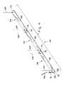
- FIG. 3is a fragmentary perspective view of an embodiment of a linear lighting system according to the present invention and shown prior to abutting the light fixtures together;
- FIG. 4is a perspective view of the linear lighting system of FIG. 3 shown after abutting the light fixtures together.
- a modular electrical interconnection system 10 for linear lightingwhich generally includes a first electrical harness 12 , a second electrical harness 14 and an electrical coupler 16 which can be electrically connected to both first electrical harness 12 and second electrical harness 14 .
- First electrical harness 12includes a first electrical connector 18 with a first plurality of terminals 20 , and a first plurality of electrical conductors 22 electrically connected to respective ones of first terminals 20 . That is, terminals 20 are typically connected to conductors 22 on a one to one basis where a single conductor 22 is connected exclusively to a single terminal 20 , although other configurations are possible depending on the type of electrical energy/signals conducted on conductors 22 . Although three conductors 22 are shown corresponding to three terminals 20 , which can be suitable for power conductors (one line, one neutral and one ground), the number of conductors 22 and terminals 20 can vary depending on the function of the linear light, and can include other power conductors, control signal conductors and data conductors, for example. First electrical harness 12 is configured for connection to a linear light 24 as shown in FIG. 3 .
- Second electrical harness 14includes a second electrical connector 26 with a second plurality of terminals 28 , and a second plurality of electrical conductors 30 electrically connected to respective ones of second terminals 28 .
- terminals 28are typically connected to conductors 30 on a one to one basis where a single conductor 30 is connected exclusively to a single terminal 28 , although other configurations are possible depending on the type of electrical energy/signals conducted on conductors 30 .
- Second terminals 28are similar in shape to first terminals 20 , both individually and collectively.
- Second electrical harness 14is configured for connection to another linear light 24 , as shown in FIG. 3 .
- Electrical coupler 16is electrically configured for connection to both first electrical connector 18 and second electrical connector 26 .
- Electrical coupler 16includes a first port 32 and a second port 34 .
- Each of first port 32 and second port 34includes a plurality of coupler terminals 36 complimentary in shape with first terminals 20 and second terminals 28 .
- Coupler terminals 36 associated with first port 32are electrically connected to respective ones of coupler terminals 36 associated with second port 34 .
- a first housing 38is associated with first connector 18 and a second housing 40 is associated with second connector 26 .
- Each of first port 32 and second port 34includes a keyway 42
- each of first housing 38 and second housing 40includes an outside contour 44 with a shape complimentary with keyway 42 .
- first electrical connector 18 and second electrical connector 26can be a female electrical connector as shown, with first terminals 20 and second terminals 28 comprising a plurality of female terminals as shown.
- Coupler terminals 36are correspondingly a plurality of male coupler terminals, as shown, and complimentary in shape with the female terminals 20 , 28 .
- connectors 18 and 26can be a male electrical connector with male terminals and coupler terminals 36 can be female terminals.
- a power infeed 46( FIG. 2 ) includes a power connector 48 , a plurality of power conductors 50 and a plurality of power terminals 52 associated with power connector 48 where each of power terminals 52 are electrically connected to a respective one of power conductors 50 .
- Power connector 48includes a power port 54 with a keyway 42 which is complimentary in shape with outside contour 44 of first housing 38 and second housing 40 .
- Power infeed 46is shown as having three conductors 50 ; however, the number of conductors 50 can vary and can be increased to include multiple power circuits, for example.
- FIGS. 3 and 4An embodiment of a linear lighting system 60 is shown in FIGS. 3 and 4 which includes a first linear light fixture 24 with a light source 62 and at least on electrical harness 12 and/or 14 electrically connected to light source 62 .
- Electrical coupler 16is electrically connected to one of connectors 18 and 26 of the first linear light fixture 24 .
- Linear lighting system 60can further include a second linear light fixture 24 having a second light source 62 with at least one electrical harness 12 and/or 14 electrically connected to light source 62 .
- the electrical harness of the second linear light fixture 24includes a second electrical connector 26 electrically connected to electrical coupler 16 .
- Light sources 62are shown as a fluorescent tube for example; however, other types of light sources are possible as are known in the art.
- each of fixtures 24can include other power circuits, ballasts and/or other power conditioning circuits, controls circuits and data circuits and/or other circuits as are known in the art.
- Fixtures 24are shown as being suspended using hangars 64 ; however, fixtures can be embodied as other types of linear light fixtures as are known in the art.
- Each of fixtures 24can include a fixture housing 66 with cutouts 68 for ingress and egress of harnesses 12 , 14 and couplers 16 .
- the present inventionprovides a method of electrically connecting and powering a linear lighting system 60 including the steps of: providing a first linear light fixture 24 including a first electrical harness 12 electrically connected to a first light source 62 and having a first electrical connector 18 ; providing an electrical coupler 16 ; electrically connecting electrical coupler 16 to first electrical connector 18 ; providing a second linear light fixture 24 including a second electrical harness 14 electrically connected to a second light source 62 and having a second electrical connector 26 ; and electrically connecting second connector 26 to electrical coupler 16 .
- the method of the present inventioncan further include the step of abutting an end 70 of the first linear light fixture 24 against an end 70 of a said second linear light fixture.
- the method of the present inventioncan further include the step of concealing first electrical harness 12 , electrical coupler 16 and second electrical harness 26 within at least one of the first linear light fixture 24 and the second linear light fixture 24 as shown particularly in FIG. 4 .
Landscapes
- Engineering & Computer Science (AREA)
- General Engineering & Computer Science (AREA)
- Arrangement Of Elements, Cooling, Sealing, Or The Like Of Lighting Devices (AREA)
Abstract
Description
This is a non-provisional application based upon U.S. provisional patent application Ser. No. 60/585,886, entitled “MODULAR WIRING FOR LINEAR LIGHTING”, filed Jul. 7, 2004.
1. Field of the Invention
The present invention relates to lighting systems, and, more particularly, to modular wiring for linear lighting systems.
2. Description of the Related Art
Lighting systems are known which use a relatively long and narrow light source such as a fluorescent tube. Other lighting systems are known which array multiple light sources generally in a line, or which array multiple light fixtures, each having at least one light source, generally in a line. Such systems are considered linear lighting systems and can be used in residential applications to provide lighting solutions for kitchens, such as under cabinets, cove lighting, over center islands, work stations and counter areas; and/or for entertainment and media rooms, and for highlighting unique and beautiful objects, for example. Commercial uses of linear lighting systems include the lighting of either office or industrial work areas, warehouses, distribution centers, retail space and the like. Linear lighting systems can be direct lighting systems or indirect lighting systems. Architectural linear lighting can be used to evenly illuminate work or retail space, walls, ceilings or floors. Typical linear lighting systems can include suspended light fixtures ordered in lengths, and ordering by the length of the fixture can provide fewer mounting locations to install. Additionally, the individual fixtures can be interconnected for functional or aesthetic reasons, and also to minimize mounting hardware and installation time. The suspended approach gives the opportunity for indirect and direct/indirect lighting, brightening up the space and eliminating a dark ceiling. The lengths of fixtures can also create a unique architectural element to the space being lighted, and further, can provide the ability to create space frames and other unique forms. Linear lighting systems are not necessarily suspended but can also be mounted in ceilings, on walls, on the underside of cabinets, or in architectural elements such as cornices, canopies and the like. Linear lighting systems are not restricted to using fluorescent light sources, but instead, can use other light sources such as light emitting diodes (LEDs), for example.
In contrast, non-linear lighting includes fixtures which are not connected, which do not light as much area as an appropriate linear light, and which are installed separately, typically resulting in extra fixtures when compared to linear lighting and more mounting hardware and more power feeds. The non-linear lighting therefore often translates into extra installation time and cost, may not be as pleasingly aesthetic, and/or may not provide as uniform lighting when compared to a linear light system.
One problem with known linear lighting systems is that if each individual fixture has its own power infeed (three conductors: line, neutral and ground, for example), time and material is wasted during installation to separately wire electrical power to each fixture. To avoid this problem, some linear lighting systems include wiring to interconnect multiple fixtures in parallel, or “daisy-chained”, thereby minimizing the number of power infeeds. One problem with this type of design is that each fixture, in order to interconnect correctly with an adjoining fixture, needs to be mounted in one of two orientations. That is, the electrical interconnections between adjacent linear lighting fixtures is directional where the interconnection at one end of a fixture can only be connected with one of two ends of an adjoining fixture. While this type of design may improve manufacturing efficiencies of the fixtures, it also disadvantageously creates problems during installation, repair and/or replacement in that a linear light fixture can be mechanically installed incorrectly in the wrong one of two orientations thereby not allowing electrical interconnection of adjoining fixtures. The wrongly orientated fixture must then be uninstalled and reinstalled in the correct orientation. The corrective process of uninstalling wrongly oriented fixtures and then reinstalling the same fixture in the correct orientation can be costly, time consuming and frustrating for installation personnel and/or customers of the linear lighting systems, particularly when a large area having many linear light fixtures is being installed. Another problem with known systems is that the electrical interconnection between fixtures can be unsightly, or can be required to be installed in a conduit for example, which takes away from the attractiveness of the fixture and/or adds to the cost of the fixture, particularly installation costs. Another problem with known systems is that the electrical interconnection can be direct hardwiring of adjoining fixtures which is time consuming during installation and therefore costly. Another problem with known linear lighting systems, including multiple linear light fixtures, is that the fixtures must be fully mechanically installed to complete the electrical interconnection, and therefore the mechanical installation must be complete prior to electrical testing. If a fixture does not operate as intended, mechanical disassembly with other fixtures must be undertaken in order to correct the electrical malfunction.
What is needed in the art is an apparatus and method of electrically interconnecting linear light fixtures which is not directional, which does not require hardwiring together adjacent fixtures, which can electrically power fixtures without complete mechanical assembly of the linear light system, and which can conceal electrical interconnection between fixtures.
The present invention provides a non-directional modular wiring system for linear lighting.
The invention comprises, in one form thereof, a modular electrical interconnection system for linear lighting, the electrical interconnection system including a first electrical harness having a first electrical connector with a first plurality of terminals, and a first plurality of electrical conductors electrically connected to respective ones of the first plurality of terminals. The first electrical harness is configured for connection to a linear light. A second electrical harness includes a second electrical connector with a second plurality of terminals, and a second plurality of electrical conductors electrically connected to respective ones of the second plurality of terminals. The second plurality of terminals are similar in shape to the first plurality of terminals. The second electrical harness is configured for connection to another linear light. An electrical coupler is electrically connected to both the first electrical connector and the second electrical connector. The electrical coupler includes a first port and a second port where each of the first port and the second port has a plurality of coupler terminals complimentary in shape with the first plurality of terminals and the second plurality of terminals. The plurality of coupler terminals associated with the first port are electrically connected to respective ones of the plurality of coupler terminals associated with the second port.
The invention comprises, in another form thereof, a linear lighting system having a first linear light fixture including a first light source and a first electrical harness electrically connected to the first light source. The first electrical harness has a first electrical connector with a first plurality of terminals, and a first plurality of electrical conductors electrically connected to respective ones of the first plurality of terminals. An electrical coupler is electrically connected to the first electrical connector where the electrical coupler includes a first port and a second port. Each of the first port and the second port includes a plurality of coupler terminals complimentary in shape with the first plurality of terminals. The plurality of coupler terminals associated with the first port are electrically connected to respective ones of the plurality of coupler terminals associated with the second port.
The invention comprises, in another form thereof, a method of electrically connecting a linear lighting system, the method including the steps of: providing a first linear light fixture including a first light source and a first electrical harness electrically connected to the first light source, the first electrical harness having a first electrical connector with a first plurality of terminals, and a first plurality of electrical conductors electrically connected to respective ones of the first plurality of terminals; providing an electrical coupler, the electrical coupler including a first port and a second port, each of the first port and the second port including a plurality of coupler terminals complimentary in shape with the first plurality of terminals, the plurality of coupler terminals associated with the first port being electrically connected to respective ones of the plurality of coupler terminals associated with the second port; electrically connecting the electrical coupler to the first electrical connector; providing a second linear light fixture having a second light source and second electrical harness electrically connected to the second light source, the second electrical harness including a second electrical connector with a second plurality of terminals, and a second plurality of electrical conductors electrically connected to respective ones of the second plurality of terminals, the second plurality of terminals similar in shape to the first plurality of terminals; and electrically connecting the second connector to the electrical coupler.
An advantage of the present invention is that it does not matter which end of a linear light fixture gets mounted toward the power source.
Another advantage of the present invention is that it provides a modular wiring for linear lighting.
Yet another advantage of the present invention is that it provides an apparatus and method of electrically interconnecting linear light fixtures which is not directional.
Yet another advantage of the present invention is that it does not require hardwiring together adjacent fixtures.
Yet another advantage of the present invention is that it electrically powers linear light fixtures without complete mechanical assembly of the linear light system.
Yet another advantage of the present invention is that it can conceal electrical interconnection between fixtures.
Yet another advantage of the present invention is that it provides for electrically testing linear light fixtures without complete mechanical assembly of the linear light system.
The above-mentioned and other features and advantages of this invention, and the manner of attaining them, will become more apparent and the invention will be better understood by reference to the following description of embodiments of the invention taken in conjunction with the accompanying drawings, wherein:
Corresponding reference characters indicate corresponding parts throughout the several views. The exemplifications set out herein illustrate one preferred embodiment of the invention, in one form, and such exemplifications are not to be construed as limiting the scope of the invention in any manner.
Referring now to the drawings, and more particularly toFIG. 1 , there is shown a modularelectrical interconnection system 10 for linear lighting which generally includes a firstelectrical harness 12, a secondelectrical harness 14 and anelectrical coupler 16 which can be electrically connected to both firstelectrical harness 12 and secondelectrical harness 14.
Firstelectrical harness 12 includes a firstelectrical connector 18 with a first plurality ofterminals 20, and a first plurality ofelectrical conductors 22 electrically connected to respective ones offirst terminals 20. That is,terminals 20 are typically connected toconductors 22 on a one to one basis where asingle conductor 22 is connected exclusively to asingle terminal 20, although other configurations are possible depending on the type of electrical energy/signals conducted onconductors 22. Although threeconductors 22 are shown corresponding to threeterminals 20, which can be suitable for power conductors (one line, one neutral and one ground), the number ofconductors 22 andterminals 20 can vary depending on the function of the linear light, and can include other power conductors, control signal conductors and data conductors, for example. Firstelectrical harness 12 is configured for connection to a linear light24 as shown inFIG. 3 .
Secondelectrical harness 14 includes a secondelectrical connector 26 with a second plurality ofterminals 28, and a second plurality ofelectrical conductors 30 electrically connected to respective ones ofsecond terminals 28. As withterminals 20 andconductors 22,terminals 28 are typically connected toconductors 30 on a one to one basis where asingle conductor 30 is connected exclusively to asingle terminal 28, although other configurations are possible depending on the type of electrical energy/signals conducted onconductors 30. Although threeconductors 30 are shown corresponding to threeterminals 28, which can be suitable for power conductors (one line, one neutral and one ground), the number ofconductors 30 andterminals 28 can vary depending on the function of the linear light, and can include other power conductors, control signal conductors and data conductors, for example.Second terminals 28 are similar in shape tofirst terminals 20, both individually and collectively. Secondelectrical harness 14 is configured for connection to anotherlinear light 24, as shown inFIG. 3 .
Afirst housing 38 is associated withfirst connector 18 and asecond housing 40 is associated withsecond connector 26. Each offirst port 32 andsecond port 34 includes akeyway 42, and each offirst housing 38 andsecond housing 40 includes anoutside contour 44 with a shape complimentary withkeyway 42.
Each of firstelectrical connector 18 and secondelectrical connector 26 can be a female electrical connector as shown, withfirst terminals 20 andsecond terminals 28 comprising a plurality of female terminals as shown.Coupler terminals 36 are correspondingly a plurality of male coupler terminals, as shown, and complimentary in shape with thefemale terminals connectors coupler terminals 36 can be female terminals.
A power infeed46 (FIG. 2 ) includes apower connector 48, a plurality ofpower conductors 50 and a plurality ofpower terminals 52 associated withpower connector 48 where each ofpower terminals 52 are electrically connected to a respective one ofpower conductors 50.Power connector 48 includes apower port 54 with akeyway 42 which is complimentary in shape withoutside contour 44 offirst housing 38 andsecond housing 40.Power infeed 46 is shown as having threeconductors 50; however, the number ofconductors 50 can vary and can be increased to include multiple power circuits, for example.
An embodiment of alinear lighting system 60 is shown inFIGS. 3 and 4 which includes a firstlinear light fixture 24 with alight source 62 and at least onelectrical harness 12 and/or14 electrically connected tolight source 62.Electrical coupler 16 is electrically connected to one ofconnectors linear light fixture 24.Linear lighting system 60 can further include a secondlinear light fixture 24 having a secondlight source 62 with at least oneelectrical harness 12 and/or14 electrically connected tolight source 62. The electrical harness of the secondlinear light fixture 24 includes a secondelectrical connector 26 electrically connected toelectrical coupler 16.Light sources 62 are shown as a fluorescent tube for example; however, other types of light sources are possible as are known in the art. Further, each offixtures 24 can include other power circuits, ballasts and/or other power conditioning circuits, controls circuits and data circuits and/or other circuits as are known in the art.Fixtures 24 are shown as being suspended usinghangars 64; however, fixtures can be embodied as other types of linear light fixtures as are known in the art. Each offixtures 24 can include afixture housing 66 withcutouts 68 for ingress and egress ofharnesses couplers 16.
In use, the present invention provides a method of electrically connecting and powering alinear lighting system 60 including the steps of: providing a firstlinear light fixture 24 including a firstelectrical harness 12 electrically connected to afirst light source 62 and having a firstelectrical connector 18; providing anelectrical coupler 16; electrically connectingelectrical coupler 16 to firstelectrical connector 18; providing a secondlinear light fixture 24 including a secondelectrical harness 14 electrically connected to a secondlight source 62 and having a secondelectrical connector 26; and electrically connectingsecond connector 26 toelectrical coupler 16. The method of the present invention can further include the step of abutting anend 70 of the firstlinear light fixture 24 against anend 70 of a said second linear light fixture. The method of the present invention can further include the step of concealing firstelectrical harness 12,electrical coupler 16 and secondelectrical harness 26 within at least one of the firstlinear light fixture 24 and the secondlinear light fixture 24 as shown particularly inFIG. 4 .
While this invention has been described as having a preferred design, the present invention can be further modified within the spirit and scope of this disclosure. This application is therefore intended to cover any variations, uses, or adaptations of the invention using its general principles. Further, this application is intended to cover such departures from the present disclosure as come within known or customary practice in the art to which this invention pertains and which fall within the limits of the appended claims.
Claims (14)
1. A linear lighting system, comprising:
a first linear light fixture including a first light source and a first electrical harness electrically connected to said first light source, said first electrical harness having a first electrical connector with a first plurality of terminals, and a first plurality of electrical conductors electrically connected to respective ones of said first plurality of terminals; and
an electrical coupler electrically connected to said first electrical connector, said electrical coupler including a first port and a second port, each of said first port and said second port including a plurality of coupler terminals complimentary in shape with said first plurality of terminals, said plurality of coupler terminals associated with said first port being electrically connected to respective ones of said plurality of coupler terminals associated with said second port, said electrical coupler having an absence of a power port.
2. The linear lighting system ofclaim 1 , further including a second linear light fixture having a second light source and second electrical harness electrically connected to said second light source, said second electrical harness including a second electrical connector with a second plurality of terminals, and a second plurality of electrical conductors electrically connected to respective ones of said second plurality of terminals, said second plurality of terminals similar in shape to said first plurality of terminals, said second connector electrically connected to said electrical coupler.
3. The linear lighting system ofclaim 2 , further including a first housing associated with said first connector and a second housing associated with said second connector, each of said first port and said second port including a keyway, each of said first housing and said second housing including an outside contour with a shape complimentary with said keyway.
4. The linear lighting system ofclaim 2 , wherein each of said first electrical connector and said second electrical connector are a female electrical connector, and each of said first plurality of terminals and said second plurality of terminals are a plurality of female terminals.
5. The linear lighting system ofclaim 4 , wherein said plurality of coupler terminals are a plurality of male coupler terminals complimentary in shape with said plurality of female terminals.
6. The linear lighting system ofclaim 2 , wherein said first linear light fixture includes a first fixture housing connected to said first light source, said second linear light fixture includes a second fixture housing connected to said second light source, said first electrical harness, said second electrical harness and said electrical coupler are concealed within at least one of said first fixture housing and said second fixture housing when said first fixture housing is butted together with said second fixture housing.
7. The linear lighting system ofclaim 2 , further including a power infeed having a power connector, a plurality of power conductors and a plurality of power terminals associated with said power connector where each of said plurality of power terminals are electrically connected to a respective one of said plurality of power conductors, said power connector including a power port with a keyway, further including a first housing associated with said first connector and a second housing associated with said second connector, each of said first housing and said second housing including an outside contour with a shape complimentary with said keyway.
8. A method of electrically connecting a linear lighting system, the method comprising the steps of:
providing a first linear light fixture including a first light source and a first electrical harness electrically connected to said first light source, said first electrical harness having a first electrical connector with a first plurality of terminals, and a first plurality of electrical conductors electrically connected to respective ones of said first plurality of terminals;
providing an electrical coupler, said electrical coupler including a first port and a second port, each of said first port and said second port including a plurality of coupler terminals complimentary in shape with said first plurality of terminals, said plurality of coupler terminals associated with said first port being electrically connected to respective ones of said plurality of coupler terminals associated with said second port, said electrical coupler having an absence of a power port;
electrically connecting said electrical coupler to said first electrical connector;
providing a second linear light fixture having a second light source and second electrical harness electrically connected to said second light source, said second electrical harness including a second electrical connector with a second plurality of terminals, and a second plurality of electrical conductors electrically connected to respective ones of said second plurality of terminals, said second plurality of terminals similar in shape to said first plurality of terminals; and
electrically connecting said second connector to said electrical coupler.
9. The method ofclaim 8 , further including the step of abutting an end of said first linear light fixture against an end of said second linear light fixture.
10. The method ofclaim 8 , further including the step of concealing said first electrical harness, said electrical coupler and said second electrical harness within at least one of said first linear light fixture and said second linear light fixture.
11. The linear lighting system ofclaim 1 , wherein said first electrical harness includes only one electrical connector.
12. The linear lighting system ofclaim 1 , wherein said electrical coupler is directly mechanically connected to said first electrical connector.
13. The method ofclaim 8 , wherein said electrical coupler is directly mechanically connected to said first and said second electrical connectors.
14. The linear lighting system ofclaim 1 , wherein said electrical coupler has an absence of a hardwire receiving station.
Priority Applications (1)
| Application Number | Priority Date | Filing Date | Title |
|---|---|---|---|
| US11/175,538US7401946B2 (en) | 2004-07-07 | 2005-07-06 | Modular wiring for linear lighting |
Applications Claiming Priority (2)
| Application Number | Priority Date | Filing Date | Title |
|---|---|---|---|
| US58588604P | 2004-07-07 | 2004-07-07 | |
| US11/175,538US7401946B2 (en) | 2004-07-07 | 2005-07-06 | Modular wiring for linear lighting |
Publications (2)
| Publication Number | Publication Date |
|---|---|
| US20060009071A1 US20060009071A1 (en) | 2006-01-12 |
| US7401946B2true US7401946B2 (en) | 2008-07-22 |
Family
ID=35541951
Family Applications (1)
| Application Number | Title | Priority Date | Filing Date |
|---|---|---|---|
| US11/175,538Expired - Fee RelatedUS7401946B2 (en) | 2004-07-07 | 2005-07-06 | Modular wiring for linear lighting |
Country Status (1)
| Country | Link |
|---|---|
| US (1) | US7401946B2 (en) |
Cited By (21)
| Publication number | Priority date | Publication date | Assignee | Title |
|---|---|---|---|---|
| US20110110085A1 (en)* | 2009-11-12 | 2011-05-12 | Cooper Technologies Company | Light Emitting Diode Module |
| US8207678B1 (en)* | 2007-03-09 | 2012-06-26 | Barco, Inc. | LED lighting fixture |
| US20130016500A1 (en)* | 2011-07-12 | 2013-01-17 | Tresco International Ltd. Co. | Modular led lighting systems and kits |
| US8568160B2 (en) | 2010-07-29 | 2013-10-29 | Covidien Lp | ECG adapter system and method |
| US20130343050A1 (en)* | 2011-03-11 | 2013-12-26 | Caishuang Hu | Innovative led tube light fixture |
| US8634901B2 (en) | 2011-09-30 | 2014-01-21 | Covidien Lp | ECG leadwire system with noise suppression and related methods |
| US8668651B2 (en) | 2006-12-05 | 2014-03-11 | Covidien Lp | ECG lead set and ECG adapter system |
| US8694080B2 (en) | 2009-10-21 | 2014-04-08 | Covidien Lp | ECG lead system |
| US8690611B2 (en) | 2007-12-11 | 2014-04-08 | Covidien Lp | ECG electrode connector |
| US8821405B2 (en) | 2006-09-28 | 2014-09-02 | Covidien Lp | Cable monitoring apparatus |
| US8840266B1 (en) | 2012-02-03 | 2014-09-23 | Paris Incorporated | Modular power-delivery system |
| USD737979S1 (en) | 2008-12-09 | 2015-09-01 | Covidien Lp | ECG electrode connector |
| US9395052B1 (en)* | 2012-11-13 | 2016-07-19 | Larry N. Shew | Modular lighting assembly |
| US9408546B2 (en) | 2013-03-15 | 2016-08-09 | Covidien Lp | Radiolucent ECG electrode system |
| US9408547B2 (en) | 2011-07-22 | 2016-08-09 | Covidien Lp | ECG electrode connector |
| USD771818S1 (en) | 2013-03-15 | 2016-11-15 | Covidien Lp | ECG electrode connector |
| US9693701B2 (en) | 2013-03-15 | 2017-07-04 | Covidien Lp | Electrode connector design to aid in correct placement |
| US20180283671A1 (en)* | 2017-03-28 | 2018-10-04 | Talent Key Holdings Limited | Plant Growth Lamp Module and Plant Growth Lamp Using the Same |
| US10103486B1 (en)* | 2017-07-28 | 2018-10-16 | Amphenol Fiber Optic Technology (Shenzhen) Co., Ltd. | Power adapter |
| US10883681B2 (en)* | 2017-11-16 | 2021-01-05 | Rose M. Castro | Apparatus for suspending decorative pendant lights |
| US20220235923A1 (en)* | 2019-06-14 | 2022-07-28 | Changzhou Lintel Display Co., Ltd | Tool-free light box |
Families Citing this family (5)
| Publication number | Priority date | Publication date | Assignee | Title |
|---|---|---|---|---|
| US8274227B2 (en) | 2010-05-06 | 2012-09-25 | Nextek Power Systems, Inc. | High-efficiency DC ballast arrangement with automatic polarity protection and emergency back-up for lighting fixture in a suspended DC-powered ceiling system |
| TWI488343B (en)* | 2013-01-17 | 2015-06-11 | Lextar Electronics Corp | Led package and light bar having the same |
| US20140362574A1 (en)* | 2013-06-05 | 2014-12-11 | Brian Barrett | Modular light emitting diode lighting system |
| DE102015000733A1 (en)* | 2014-07-29 | 2016-02-04 | Seifert Mtmsystems (Malta) Ltd. | Control cabinet luminaire with light sources based on light-emitting diodes |
| FI20145907A (en)* | 2014-10-16 | 2016-04-17 | Savo Solar Oy | Solar Thermal Collectors |
Citations (14)
| Publication number | Priority date | Publication date | Assignee | Title |
|---|---|---|---|---|
| US4415217A (en) | 1981-07-16 | 1983-11-15 | Raychem Corporation | Cable joining connector and method |
| US4639841A (en) | 1986-01-13 | 1987-01-27 | Salestrom Charles B | Modular lighting system |
| US5226724A (en) | 1992-06-17 | 1993-07-13 | Kanarek Shepard S | Modular, user-installed, surface-mounted, fluorescent lighting system |
| US5559681A (en) | 1994-05-13 | 1996-09-24 | Cnc Automation, Inc. | Flexible, self-adhesive, modular lighting system |
| US5679023A (en) | 1995-08-23 | 1997-10-21 | Nsi Enterprises, Inc. | Female cable connector head for relocatable wiring systems and methods for manufacture thereof |
| US5702176A (en)* | 1994-12-12 | 1997-12-30 | Jji Lighting Group, Inc. | Modular connector device |
| US20010036070A1 (en) | 2000-04-12 | 2001-11-01 | Compagnucci - S.P.A. | Lighting modular panel for modular kitchen furniture |
| US6422891B1 (en) | 2000-01-27 | 2002-07-23 | Shining Blick Enterprise Co., Ltd. | Fast connecting structure for fitting lights |
| US6641294B2 (en)* | 2002-03-22 | 2003-11-04 | Emteq, Inc. | Vehicle lighting assembly with stepped dimming |
| US20030223235A1 (en) | 2002-06-03 | 2003-12-04 | Ferenc Mohacsi | LED accent lighting units |
| US6659622B2 (en) | 2000-11-24 | 2003-12-09 | Moriyama Sangyo Kabushiki Kaisha | Illumination system and illumination unit |
| US6702453B2 (en)* | 2001-10-26 | 2004-03-09 | Birchwood Lighting, Inc. | Flexible light fixture |
| US6932495B2 (en)* | 2001-10-01 | 2005-08-23 | Sloanled, Inc. | Channel letter lighting using light emitting diodes |
| US6964504B2 (en)* | 2003-04-01 | 2005-11-15 | Hubbell Incorporated | Lighting system for direct wiring electric luminaires |
- 2005
- 2005-07-06USUS11/175,538patent/US7401946B2/ennot_activeExpired - Fee Related
Patent Citations (14)
| Publication number | Priority date | Publication date | Assignee | Title |
|---|---|---|---|---|
| US4415217A (en) | 1981-07-16 | 1983-11-15 | Raychem Corporation | Cable joining connector and method |
| US4639841A (en) | 1986-01-13 | 1987-01-27 | Salestrom Charles B | Modular lighting system |
| US5226724A (en) | 1992-06-17 | 1993-07-13 | Kanarek Shepard S | Modular, user-installed, surface-mounted, fluorescent lighting system |
| US5559681A (en) | 1994-05-13 | 1996-09-24 | Cnc Automation, Inc. | Flexible, self-adhesive, modular lighting system |
| US5702176A (en)* | 1994-12-12 | 1997-12-30 | Jji Lighting Group, Inc. | Modular connector device |
| US5679023A (en) | 1995-08-23 | 1997-10-21 | Nsi Enterprises, Inc. | Female cable connector head for relocatable wiring systems and methods for manufacture thereof |
| US6422891B1 (en) | 2000-01-27 | 2002-07-23 | Shining Blick Enterprise Co., Ltd. | Fast connecting structure for fitting lights |
| US20010036070A1 (en) | 2000-04-12 | 2001-11-01 | Compagnucci - S.P.A. | Lighting modular panel for modular kitchen furniture |
| US6659622B2 (en) | 2000-11-24 | 2003-12-09 | Moriyama Sangyo Kabushiki Kaisha | Illumination system and illumination unit |
| US6932495B2 (en)* | 2001-10-01 | 2005-08-23 | Sloanled, Inc. | Channel letter lighting using light emitting diodes |
| US6702453B2 (en)* | 2001-10-26 | 2004-03-09 | Birchwood Lighting, Inc. | Flexible light fixture |
| US6641294B2 (en)* | 2002-03-22 | 2003-11-04 | Emteq, Inc. | Vehicle lighting assembly with stepped dimming |
| US20030223235A1 (en) | 2002-06-03 | 2003-12-04 | Ferenc Mohacsi | LED accent lighting units |
| US6964504B2 (en)* | 2003-04-01 | 2005-11-15 | Hubbell Incorporated | Lighting system for direct wiring electric luminaires |
Cited By (33)
| Publication number | Priority date | Publication date | Assignee | Title |
|---|---|---|---|---|
| US8821405B2 (en) | 2006-09-28 | 2014-09-02 | Covidien Lp | Cable monitoring apparatus |
| US8668651B2 (en) | 2006-12-05 | 2014-03-11 | Covidien Lp | ECG lead set and ECG adapter system |
| US9072444B2 (en) | 2006-12-05 | 2015-07-07 | Covidien Lp | ECG lead set and ECG adapter system |
| US8207678B1 (en)* | 2007-03-09 | 2012-06-26 | Barco, Inc. | LED lighting fixture |
| US8525440B1 (en) | 2007-03-09 | 2013-09-03 | Barco, Inc. | LED lighting fixture |
| US8690611B2 (en) | 2007-12-11 | 2014-04-08 | Covidien Lp | ECG electrode connector |
| US9107594B2 (en) | 2007-12-11 | 2015-08-18 | Covidien Lp | ECG electrode connector |
| US8795004B2 (en) | 2007-12-11 | 2014-08-05 | Covidien, LP | ECG electrode connector |
| USD737979S1 (en) | 2008-12-09 | 2015-09-01 | Covidien Lp | ECG electrode connector |
| US8694080B2 (en) | 2009-10-21 | 2014-04-08 | Covidien Lp | ECG lead system |
| US8897865B2 (en) | 2009-10-21 | 2014-11-25 | Covidien Lp | ECG lead system |
| US20110110085A1 (en)* | 2009-11-12 | 2011-05-12 | Cooper Technologies Company | Light Emitting Diode Module |
| US8632214B1 (en) | 2009-11-12 | 2014-01-21 | Cooper Technologies Company | Light modules with uninterrupted arrays of LEDs |
| US8308320B2 (en)* | 2009-11-12 | 2012-11-13 | Cooper Technologies Company | Light emitting diode modules with male/female features for end-to-end coupling |
| US8568160B2 (en) | 2010-07-29 | 2013-10-29 | Covidien Lp | ECG adapter system and method |
| US20130343050A1 (en)* | 2011-03-11 | 2013-12-26 | Caishuang Hu | Innovative led tube light fixture |
| US8545045B2 (en)* | 2011-07-12 | 2013-10-01 | Rev-A-Shelf Company, Llc | Modular LED lighting systems and kits |
| US20130016500A1 (en)* | 2011-07-12 | 2013-01-17 | Tresco International Ltd. Co. | Modular led lighting systems and kits |
| US9737226B2 (en) | 2011-07-22 | 2017-08-22 | Covidien Lp | ECG electrode connector |
| US9408547B2 (en) | 2011-07-22 | 2016-08-09 | Covidien Lp | ECG electrode connector |
| US8634901B2 (en) | 2011-09-30 | 2014-01-21 | Covidien Lp | ECG leadwire system with noise suppression and related methods |
| US9375162B2 (en) | 2011-09-30 | 2016-06-28 | Covidien Lp | ECG leadwire system with noise suppression and related methods |
| US8840266B1 (en) | 2012-02-03 | 2014-09-23 | Paris Incorporated | Modular power-delivery system |
| US9395052B1 (en)* | 2012-11-13 | 2016-07-19 | Larry N. Shew | Modular lighting assembly |
| US9408546B2 (en) | 2013-03-15 | 2016-08-09 | Covidien Lp | Radiolucent ECG electrode system |
| USD771818S1 (en) | 2013-03-15 | 2016-11-15 | Covidien Lp | ECG electrode connector |
| US9693701B2 (en) | 2013-03-15 | 2017-07-04 | Covidien Lp | Electrode connector design to aid in correct placement |
| US9814404B2 (en) | 2013-03-15 | 2017-11-14 | Covidien Lp | Radiolucent ECG electrode system |
| US20180283671A1 (en)* | 2017-03-28 | 2018-10-04 | Talent Key Holdings Limited | Plant Growth Lamp Module and Plant Growth Lamp Using the Same |
| US10103486B1 (en)* | 2017-07-28 | 2018-10-16 | Amphenol Fiber Optic Technology (Shenzhen) Co., Ltd. | Power adapter |
| US10883681B2 (en)* | 2017-11-16 | 2021-01-05 | Rose M. Castro | Apparatus for suspending decorative pendant lights |
| US20220235923A1 (en)* | 2019-06-14 | 2022-07-28 | Changzhou Lintel Display Co., Ltd | Tool-free light box |
| US11828443B2 (en)* | 2019-06-14 | 2023-11-28 | Changzhou Lintel Display Co., Ltd | Tool-free light box |
Also Published As
| Publication number | Publication date |
|---|---|
| US20060009071A1 (en) | 2006-01-12 |
Similar Documents
| Publication | Publication Date | Title |
|---|---|---|
| US7401946B2 (en) | Modular wiring for linear lighting | |
| US10660172B2 (en) | Modular light fixture with power pack | |
| CA1101114A (en) | Lighting and power system and connectors therefor | |
| US9673582B2 (en) | Modular housing and track assemblies for tubular lamps | |
| US7380957B2 (en) | Method and apparatus for joining linear lighting fixtures to eliminate sag | |
| US11015776B2 (en) | Architectural linear luminaire | |
| US20170074474A1 (en) | Led lighting systems and methods of installation | |
| US7114827B2 (en) | Lighting assembly | |
| US20070161270A1 (en) | Modules for interconnection of sensors, actuators and application devices | |
| US20090086487A1 (en) | Flexible LED Lighting Systems, Fixtures and Method of Installation | |
| US20080197702A1 (en) | Programmable infrastructure system | |
| US20060276068A1 (en) | Circuit selectable receptacle | |
| US20180283668A1 (en) | Modular power system for cabinets | |
| JPS5854478B2 (en) | Electrical connection and switching devices for lighting equipment | |
| US20030207612A1 (en) | Rail electrical connector system | |
| US7144264B2 (en) | Add-on electrical distribution assembly | |
| US6388190B1 (en) | Modular power assembly with switch | |
| US12410909B2 (en) | Modular lighting system assembly | |
| US20200260541A1 (en) | Hinged remote driver box for light fixture | |
| US20030001113A1 (en) | Device to disinfect air or surfaces with radiation and method therefor | |
| US10119691B2 (en) | Systems and methods for improved lighting systems | |
| US6948972B2 (en) | Overhead lighting splitter | |
| WO2017127275A1 (en) | Hot-swappable system for and method of distributing electrical power and/or data to at least one electrical device | |
| GB2435131A (en) | Modular wiring system | |
| US11047553B2 (en) | Low profile large area luminaire |
Legal Events
| Date | Code | Title | Description |
|---|---|---|---|
| AS | Assignment | Owner name:PENT TECHNOLOGIES, INC., INDIANA Free format text:ASSIGNMENT OF ASSIGNORS INTEREST;ASSIGNOR:LAUKHUF, GREGG E.;REEL/FRAME:016870/0249 Effective date:20050711 | |
| AS | Assignment | Owner name:GROUP DEKKO, INC., INDIANA Free format text:MERGER;ASSIGNOR:PENT TECHNOLOGIES, INC.;REEL/FRAME:021936/0719 Effective date:20071227 Owner name:GROUP DEKKO, INC.,INDIANA Free format text:MERGER;ASSIGNOR:PENT TECHNOLOGIES, INC.;REEL/FRAME:021936/0719 Effective date:20071227 | |
| AS | Assignment | Owner name:WELLS FARGO CAPITAL FINANCE, LLC, AS AGENT, ILLINO Free format text:SECURITY AGREEMENT;ASSIGNOR:GROUP DEKKO, INC.;REEL/FRAME:026503/0966 Effective date:20110624 | |
| REMI | Maintenance fee reminder mailed | ||
| LAPS | Lapse for failure to pay maintenance fees | ||
| STCH | Information on status: patent discontinuation | Free format text:PATENT EXPIRED DUE TO NONPAYMENT OF MAINTENANCE FEES UNDER 37 CFR 1.362 | |
| FP | Lapsed due to failure to pay maintenance fee | Effective date:20120722 |