US7401453B2 - Packaging system having loading carousel - Google Patents
Packaging system having loading carouselDownload PDFInfo
- Publication number
- US7401453B2 US7401453B2US11/437,394US43739406AUS7401453B2US 7401453 B2US7401453 B2US 7401453B2US 43739406 AUS43739406 AUS 43739406AUS 7401453 B2US7401453 B2US 7401453B2
- Authority
- US
- United States
- Prior art keywords
- loading
- carousel
- along
- cartons
- carriers
- Prior art date
- Legal status (The legal status is an assumption and is not a legal conclusion. Google has not performed a legal analysis and makes no representation as to the accuracy of the status listed.)
- Active
Links
- 238000004806packaging method and processMethods0.000titleclaimsabstractdescription87
- 239000000969carrierSubstances0.000claimsdescription50
- 230000032258transportEffects0.000claimsdescription25
- 238000011144upstream manufacturingMethods0.000claimsdescription16
- 238000013459approachMethods0.000claimsdescription2
- 230000007246mechanismEffects0.000description17
- 230000000712assemblyEffects0.000description5
- 238000000429assemblyMethods0.000description5
- 230000033001locomotionEffects0.000description5
- 230000010006flightEffects0.000description3
- 230000009467reductionEffects0.000description3
- 238000010276constructionMethods0.000description2
- 238000004519manufacturing processMethods0.000description2
- 238000012546transferMethods0.000description2
- 238000007792additionMethods0.000description1
- 239000011324beadSubstances0.000description1
- 230000006835compressionEffects0.000description1
- 238000007906compressionMethods0.000description1
- 238000013461designMethods0.000description1
- 230000000694effectsEffects0.000description1
- 238000009963fullingMethods0.000description1
- 239000003292glueSubstances0.000description1
- 229940090441infedDrugs0.000description1
- 238000012423maintenanceMethods0.000description1
- 238000000034methodMethods0.000description1
- 238000012986modificationMethods0.000description1
- 230000004048modificationEffects0.000description1
- 238000012856packingMethods0.000description1
- 239000000123paperSubstances0.000description1
- 239000011087paperboardSubstances0.000description1
- 230000008569processEffects0.000description1
- 238000000926separation methodMethods0.000description1
- 230000035939shockEffects0.000description1
- 238000013519translationMethods0.000description1
Images


Classifications
- B—PERFORMING OPERATIONS; TRANSPORTING
- B65—CONVEYING; PACKING; STORING; HANDLING THIN OR FILAMENTARY MATERIAL
- B65B—MACHINES, APPARATUS OR DEVICES FOR, OR METHODS OF, PACKAGING ARTICLES OR MATERIALS; UNPACKING
- B65B21/00—Packaging or unpacking of bottles
- B65B21/24—Enclosing bottles in wrappers
- B65B21/242—Enclosing bottles in wrappers in collapsed carton sleeves
- B—PERFORMING OPERATIONS; TRANSPORTING
- B65—CONVEYING; PACKING; STORING; HANDLING THIN OR FILAMENTARY MATERIAL
- B65B—MACHINES, APPARATUS OR DEVICES FOR, OR METHODS OF, PACKAGING ARTICLES OR MATERIALS; UNPACKING
- B65B43/00—Forming, feeding, opening or setting-up containers or receptacles in association with packaging
- B65B43/26—Opening or distending bags; Opening, erecting, or setting-up boxes, cartons, or carton blanks
- B65B43/30—Opening or distending bags; Opening, erecting, or setting-up boxes, cartons, or carton blanks by grippers engaging opposed walls, e.g. suction-operated
- B—PERFORMING OPERATIONS; TRANSPORTING
- B65—CONVEYING; PACKING; STORING; HANDLING THIN OR FILAMENTARY MATERIAL
- B65B—MACHINES, APPARATUS OR DEVICES FOR, OR METHODS OF, PACKAGING ARTICLES OR MATERIALS; UNPACKING
- B65B43/00—Forming, feeding, opening or setting-up containers or receptacles in association with packaging
- B65B43/42—Feeding or positioning bags, boxes, or cartons in the distended, opened, or set-up state; Feeding preformed rigid containers, e.g. tins, capsules, glass tubes, glasses, to the packaging position; Locating containers or receptacles at the filling position; Supporting containers or receptacles during the filling operation
- B65B43/50—Feeding or positioning bags, boxes, or cartons in the distended, opened, or set-up state; Feeding preformed rigid containers, e.g. tins, capsules, glass tubes, glasses, to the packaging position; Locating containers or receptacles at the filling position; Supporting containers or receptacles during the filling operation using rotary tables or turrets
- B—PERFORMING OPERATIONS; TRANSPORTING
- B65—CONVEYING; PACKING; STORING; HANDLING THIN OR FILAMENTARY MATERIAL
- B65B—MACHINES, APPARATUS OR DEVICES FOR, OR METHODS OF, PACKAGING ARTICLES OR MATERIALS; UNPACKING
- B65B65/00—Details peculiar to packaging machines and not otherwise provided for; Arrangements of such details
- B65B65/003—Packaging lines, e.g. general layout
- B—PERFORMING OPERATIONS; TRANSPORTING
- B65—CONVEYING; PACKING; STORING; HANDLING THIN OR FILAMENTARY MATERIAL
- B65B—MACHINES, APPARATUS OR DEVICES FOR, OR METHODS OF, PACKAGING ARTICLES OR MATERIALS; UNPACKING
- B65B5/00—Packaging individual articles in containers or receptacles, e.g. bags, sacks, boxes, cartons, cans, jars
- B65B5/02—Machines characterised by incorporation of means for making the containers or receptacles
- B65B5/024—Machines characterised by incorporation of means for making the containers or receptacles for making containers from preformed blanks
Definitions
- the present inventionrelates generally to a high speed packaging machine having a loading carousel.
- the packaging of articles such as bottles, cans, and other similar articles in cartons or other containersis a highly automated process, with conventional automated packaging equipment generally being run at high packaging speeds in order to maximize output.
- articles to be packagedare fed into the packaging machine in a line or series of lines along an infeed conveyor, after which the articles are grouped together in various standard configurations or groupings, such as four, six, eight, twelve, or twenty-four pack configurations.
- the groups of articlesare then packaged into a box, a carton, or other type of container.
- the placement of the articles within a containercan be done in a variety of ways, depending upon the type of package in which the articles are to be placed. For example, the bottoms of cartons can be opened and the cartons then placed over selected groups of articles as the articles are moved along a transport path.
- FIG. 1A conventional packaging machine is shown in FIG. 1 .
- the machine functionsgenerally are performed in a line extending through the machine.
- product meteringis operated by star wheels at Station 1 .
- product selection blocksseparate the product into groups to be loaded into individual cartons.
- a carousel pick-upselects individual cartons for loading.
- a carton transportcontrols the carton through plows and an opening assembly.
- the carton openeropens the cartons between pairs of vacuum manifold assemblies.
- the carouselvertically lowers the opened cartons over and onto the product groups.
- a closing sectioncloses the carton base about the bottle group contained therein and compression is applied on the underside of the discharge belt to secure the carton in a closed position.
- the linear footprint of the machinemust be large in order to ensure that the path of travel of the cartons is sufficient to ensure that the cartons are fully opened before being placed over a group of articles.
- plant spaceoften is at a premium and it is not always possible to extend machinery to an optimal size.
- the speed at which the articles are packagedmust then typically be reduced in order to ensure that the cartons are fully opened prior to packaging the articles therein. Output is accordingly reduced.
- the conventional packaging machinealso has a large vertical height. As shown in FIG. 1 , cartons are picked up at Station 3 at a raised position and lowered onto the bottles at Station 6 . Because the carton pickup and carton loading steps are performed along a line, the height of the carousel must be sufficient to accommodate the highest point of the stroke (i.e., before pickup), and the lowest point of the stroke (i.e., at loading).
- the present inventiongenerally is directed to a high speed packaging system for packaging various types of articles in a variety of different configurations of containers or cartons.
- the articlessuch as bottles, cans, or the like, generally will be fed into and through the packaging system of the present invention along a path of travel on an infeed conveyor on an upstream side of the packaging system.
- the articlescan be separated in one or more lanes of products, in side by side or in staggered configurations.
- the articlesAs the articles are fed into the upstream or receiving end of the packaging system, the articles pass through a selector station for selecting and grouping the articles into groups. As the articles are separated into their packaging groups, the groups of articles are further transferred to a packaging line along which the groups of articles are placed into containers.
- the packaging linemay generally extend along a path substantially parallel to the path of travel of the articles along the infeed conveyor, although other orientations are possible.
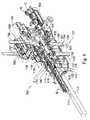
- a carton loading carouselwill be positioned adjacent to and extend parallel to the packaging line, and includes a series of carton carriers moving thereabout.
- the carriersare moved about the carousel from a carton pickup point along a first side of the carousel, and subsequently moved into a loading position along a second side of the carousel.
- the carrierscan be moved along a cam track that extends about the periphery of the carousel to raise and lower the cartons as the cartons are moved between pickup and loading positions. At this loading position, the cartons are engaged with a selected group of articles moving along the packaging line.
- the cartonscan be lowered as they approach their loading position, with the cartons being moved forwardly and downwardly over the selected group of articles to load the articles within the cartons.
- the cartonscan be moved from a lowered position passing below an article infeed line for the articles, to an elevated loading position. As the cartons are moved upwardly beneath a selected group of articles, the articles are loaded into one or more compartments of the cartons from above the cartons.
- the cartonsmay be provided by a carton infeed system and opened in a carton opener.
- the opening and pickup of the cartonsmay be accomplished along an initial portion of a carton loading path that is substantially parallel to but extending opposite or spaced from the packaging line so that two sides of the loading carousel are utilized.
- use of two sides of the loading carouselallows the packaging system to open and load cartons with groups of articles in a significantly reduced length, space, and/or footprint, without reducing packaging speed. Also, because the pickup stroke can occur on one side of the carousel, and the loading stroke can occur on the opposite side, the loading carousel can be significantly shorter in height than conventional carousels. In addition, the relatively small size of the loading carousel reduces the mass of moving parts in the carousel, meaning a smaller inertia during operation.
- FIG. 1is a perspective view of a conventional prior art article packaging system.
- FIG. 2is a top plan schematic view of a packaging system according to an embodiment of the present invention.
- FIG. 3is a perspective partial schematic view of the packaging system.
- FIG. 4Ais a perspective partial schematic view of the packaging system.
- FIG. 4Bis a partial perspective view showing the operation of a loading carousel according to an embodiment of the present invention.
- FIG. 5is a perspective partial schematic view of the packaging system illustrating a carton infeed system.
- FIG. 6is a side elevational partial schematic view of the packaging system.
- FIG. 7is a partial perspective view showing the operation of the loading carousel.
- FIG. 8is a perspective view of an additional embodiment of a packaging system according to the present invention.
- FIG. 9is a side elevational view showing the loading of products into basket type packages according to the embodiment of FIG. 8 .
- FIG. 10is an end view of the upstream or inlet end of the packaging system of FIG. 8 .
- FIG. 11is an end view of the downstream or outlet end of the packaging system of FIG. 8 .
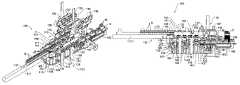
- FIGS. 2-7illustrate a high speed packaging system 10 according to a first embodiment of the present invention.
- the packaging system 10generally is designed to provide a substantially continuous motion system for high speed packaging of various types of articles in a variety of configurations of containers, including, for example, six-pack, four-pack, or eight-pack cartons, as well as smaller or larger configurations.
- the packaging system embodiment discussed in detail belowis described as loading bottles B into cartons C to form packages P.
- the packaging system 10has a first, upstream or inlet end 12 and a second, downstream or outlet end 13 .
- the packaging system 10comprises the following general components: a carton infeed system 90 having an opener 93 for providing opened cartons C in the system 10 , a loading carousel 60 for loading bottles B in the cartons C, an article transport or infeed conveyor 16 for providing bottles B in the system 10 , a selector station 30 for metering the flow of bottles B into the loading carousel 60 , as indicated by arrow 42 , a packaging line 45 for moving the cartons C and bottles B during loading, a closing mechanism 86 for engaging and closing the bottoms of the cartons C, and a outlet mechanism 110 for forwarding the packs P down the conveyor line for further handling and/or packaging.
- the packaging system 10generally will also include a frame (not shown) or support housing.
- the framecan include, for example, one or more bays or doors to enable access to the packaging machine 10 .
- the outlet mechanism 110can be, for example, a two-way divider, as shown in FIG. 2 .
- the loading carousel 60has a first side 8 and a second side 9 , both of which are used for opening and loading of cartons C.
- Using two sides 8 , 9 of the carousel 60 for opening and loadinghas the effect of reducing both the required stroke and the number of flights or carriers required for opening and loading the cartons C.
- the required stroke and number of flightscan be reduced, for example, by about half, when compared to conventional packaging machines having similar output capabilities.
- the reduction of the number of flights or carriers requiredaccordingly reduces the plan area or footprint of the packaging system 10 . This significant reduction in footprint in turn conserves valuable shop space.
- the reduction in strokereduces the vertical height of the packaging system 10 , in particular the height of the loading carousel 60 .
- the carton infeed system 90 having the opener 93is located on the first side 8 of the loading carousel 60 .
- the article transport conveyor 16 , the selector station 30 , and the packaging line 45are located on the second side 9 of the loading carousel 60 .
- the structure and operation of the packaging system 10are discussed in detail below with reference to FIGS. 2-7 .
- the article transport conveyor 16provides a supply of bottles B to the loading carousel 60 .
- the article transport conveyor 16generally is positioned at the upstream end 12 of the packaging system 10 for receiving the bottles B and moving them along an infeed path of travel indicated by arrow 17 .
- the article transport conveyor 16generally may be a belt, chain or other conventional type of conveyor having an upper surface 18 along which the bottles B are moved.
- the article transport conveyor 16can include, for example, dividers 19 for separating the bottles B into one or more lanes 21 , 22 .
- the article transport conveyor 16further includes a first or proximal end 23 where the bottles B are received from an upstream production line (not shown), and a second or distal end 24 where the bottles B are engaged and transferred from the article transport conveyor 16 by the selector station 30 .
- the selector station 30meters the flow of bottles B into the loading carousel 60 by ordering the bottles B into groups that are conveyed along the packaging line 45 .
- the selector station 30generally may include a series of metering or star wheels 31 having product receiving recesses 32 formed thereabout. The star wheels 31 engage and meter the flow of bottles B moving along the article transport conveyor 16 , and redirect the lanes 21 , 22 of bottles B toward a pair of selectors 33 .
- the selectors 33may be conventional and are schematically illustrated in FIGS. 3 , 4 A and 4 B.
- the selectors 33may generally include upper and lower support plates and a series of pairs or sets of selector arms mounted therebetween.
- Each selector armmay include an article engaging or separating plate mounted at a front or proximal end thereof, with each separating plate having a series of teeth defining a series of recesses therebetween.
- the selector armscan be moveable radially from a retracted, initial position for engaging and moving a series of bottles B, e.g., 2, 3, 4, etc., depending upon how many bottles B are metered to carousel 60 , as the selector arms are rotated with the rotation of the selectors 33 .
- the selectors 33can be configured to place bottles B into any desired configuration group, and typically will move at a different rate as they engage their respective groups of bottles B so as to create a separation or stagger between the groups of bottles to form a desired package grouping configuration.
- the bottle groupshave a 2 ⁇ 3 configuration.
- the carton infeed system 90 and the opener 93provide a supply of cartons to the loading carousel 60 .
- Cartons Care initially fed into the packaging system 10 at the carton infeed system 90 .
- the cartons Ccan be infed at a variety of points or locations, for example.
- the infeed system 90can include, for example, a carton infeed conveyor 97 that provides an initial supply of cartons C, and a carton transport conveyor 96 that transports the cartons C through the opener 93 and along the first side 8 of the carousel 60 .
- the carton infeed system 90may be positioned slightly downstream from the loading carousel 60 and opposite to the closing mechanism 86 , and provides a substantially continuous flow or line of opened cartons C to the loading carousel 60 .
- the carton infeed system 90may be positioned in a vertically raised arrangement above the outlet mechanism 110 .
- the opener 93can include a carton opening apparatus or mechanism such as disclosed in U.S. Pat. No. 6,240,707, the entire disclosure of which is incorporated herein by reference.
- the opener 93can include a frame 94 having a guide slot or track.
- a series of carton opening assemblies 98are transported about the frame 94 , moving between a carton pickup or engaging position 99 and a discharge position 101 , in which the opened cartons C are released and further conveyed along the carton transport conveyor 96 .
- the opening assemblies 98are conveyed about the opener 93 for picking up flat folded cartons C and opening the cartons to an opened position before release at the discharge position 101 .
- the opener 93also can include an adjustable internal opener cam that generally reduces the maximum height of the cartons C, which reduces the opener head mast/radius. Further, an adjustable internal opener cam can be provided for enabling opening of varying size cartons.
- the loading carousel 60loads the bottles B supplied by the selector station 30 into the opened cartons C provided by the opener 93 .
- Two sides 8 , 9 of the loading carousel 60are utilized in the packaging system 10 .
- the structure and operation of the loading carousel 60are discussed in detail below.
- the loading carousel 60is mounted adjacent to and extends along the upstream or inlet end 49 of the packaging line 45 .
- the loading carousel 60includes upstream and downstream rotating supports 62 and 63 , respectively, that are engaged with upper and lower chains or belts 64 and 66 , respectively, that are moved about a substantially elliptical path by the rotation of the upstream and downstream supports 62 and 63 .
- Rotationcan be effected by motors or other drive mechanisms, for example.
- the rotating supports 62 and 63may be sprockets having teeth that engage the chains 64 , 66 , respectively, for example.
- the rotating supports 62 , 63may alternatively be gear or belt-driven.
- the carton transport conveyor 96 on the first side 8 of the loading carousel 60may be spaced from and extend parallel to the packaging line 45 on the second side 9 of the carousel 60 .
- the second side 9 of the loading carousel 60may extend from a point slightly upstream from the inlet end 49 of the packaging line 45 approximately to the discharge end 51 of the packaging line 45 .
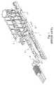
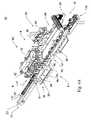
- FIGS. 6 and 7illustrate the first side 8 of the loading carousel 60 , where the carousel 60 receives and picks up the opened cartons C from the carton transport conveyor 96 .
- the loading carousel 60includes a series of carton carriers 71 that are carried along an elliptical path in the direction of arrows 72 ( FIG. 3 ) by the rotation of the loading carousel 60 .
- the rotationconveys the carriers 71 to first, lowered pickup position 73 , where the carriers 71 pick up the cartons C.
- the carriers 71subsequently transport the cartons C to a second, lowered loading or article receiving position 74 ( FIG. 4B ) along the second side 9 of the carousel 60 , where the cartons C are placed about groups of bottles B.
- Each of the carriers 71generally will include a spaced pair of arms 76 and 77 extending vertically downwardly from a laterally extending support plate 78 .
- Each support plate 78is attached to and is carried by a pair of vertically extending support rods 79 so as to transport the carriers 71 about the periphery of the loading carousel 60 , while also allowing for vertical translation of the carriers 71 .
- Each support plate 78may be connected to a block 81 , which may be connected to one of each pair of the support rods 79 by an angled plate 82 .
- the carriers 71also are typically operated without a back wall to allow better carton side guides at the pick up position 73 , and can be adjusted by a screw, or otherwise, for example, to accommodate various container sizes.
- a cam follower or guide 83may be attached to each of the blocks 81 or to the support plates 78 . Each cam follower 83 will generally engage and move along a cam track 84 in the loading carousel 60 as the carriers 71 are moved about the carousel 60 .
- the cam track 84generally has a first, pickup cam profile or side 84 A. extending along the first side 8 of the carousel 60 , and a second or loading side profile 84 B extending along the second side 9 of the carousel 60 .
- the carriers 71are moved between the lowered and raised positions shown in FIGS. 4B and 7 , respectively, during the transport of the cartons C from the pickup position 73 ( FIG.
- the cartons Care then conveyed into alignment with the bottle groups being formed therebeneath along the packaging line 45 , and then lowered in timed relation to the movement of the groups of bottles B along the packaging line 45 so that each carton C is matched with a group of bottles B and thereafter progressively lowered down over the bottles at the article loading position 74 .
- the cartons Cmay have channels, cavities or other compartments in which the bottles B are received, as illustrated in FIG. 4B .
- a plow 80may be included to manipulate base flaps of the cartons C, if present, and may function to hold the flaps outwardly so that the cartons C are more easily lowered over the bottles B.
- the opened bottom flaps of the bottles Bare not shown in the Figures.
- the closing mechanism 86may be conventional in operation and can include a flap tucking mechanism that engages and tucks locking tabs or flaps along the bottom surfaces of the cartons into a locked arrangement.
- the closing mechanism 86can include a folder/gluer mechanism that applies a bead of glue between the bottom flaps of the cartons and thereafter presses the bottom flaps into engagement with one another to seal them together.
- the finished, closed cartons Care then fed further downstream for transfer to the discharge or outlet mechanism 110 .
- the packaging line 45extends in the direction of arrow 46 , and may be spaced from and substantially parallel to the path of travel 17 of the flow of products on the infeed conveyor 16 .
- the packaging line 45may include, for example, a conveyor belt 47 , although other, similar types of conveying mechanisms also can be used, for transport of the groups of bottles B.
- the conveyor belt 47moves about a substantially elliptical path between the upstream end 49 and the downstream end 51 , at which point the loaded packages P are delivered to the outlet mechanism 110 .
- the system 10 detailed hereincan utilize a variety of drives, including servo-motors, stepper motors, AC or DC motors, pneumatic or hydraulic drives that operate, or are connected to, the following operative elements: the loading carousel, the opener, the closing mechanism, the starwheels, the selector station, the container infeed, etc.
- Other unitscan be mechanically or servo driven or can slave off of existing drives (e.g., carton feeding could drive off of the carousel drive).
- the packaging system 10 described hereincan utilize a standard two lane infeed conveyor arrangement as illustrated.
- the system 10 layoutcan also be widened with bottles B infeeding alongside the carton feed and around the outside of the carousel 60 head shaft.
- the starwheels 31 and selectors 33may be of a design and construction as found in the Autoflex 1500 as manufactured by Graphic Packaging International, Inc.
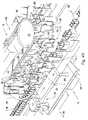
- FIGS. 8-11illustrate a second embodiment of the packaging system 100 according to the principles of the present invention.
- the packaging system 100( FIGS. 8 and 11 ) of the present embodiment will include a loading carousel 110 for loading articles or products, such as bottles B or other similar products, into cartons C, here illustrated as basket-type cartons or containers, each having a series of compartments defined therein.
- the articles to be packagedsuch as bottles B
- the article infeed conveyor 111typically enters the packing system 100 at the upstream end 113 of the packaging system, generally at an elevated position with respect to the loading carousel 110 and terminating at a discharge point 114 .
- the loading carousel 110includes a substantially elliptically shaped frame 116 having a first side 117 along which the open carton C are engaged and picked up at an initial or pickup point 118 ( FIG. 8 ).
- the cartonsthereafter are conveyed about the loading carousel along a loading path in the direction of arrow 119 under the article infeed conveyor 111 , to a loading point 120 along a second side 121 of the loading carousel.
- the loading carousel 110further includes a series of carriers 122 for conveying cartons about their loading path indicated by arrow 119 . As illustrated in FIGS.
- each of the carriers 122generally includes a base 123 that is slideably mounted on a pair of vertically extending support rods 124 that are attached to the frame 116 of the loading carousel so as to be rotated therewith to move the carriers about the loading path 119 .
- Container or carton supports 126are mounted on the base of each carrier 122 , and are typically vertically spaced from their base 123 by upstanding plates or brackets 127 .
- Each of the container supportsgenerally is a U- or C-shaped member having front and rear walls 128 and 129 , respectively, with a longitudinally extending section or portion 131 therebetween.
- the container supports 126further are spaced apart, as indicated in FIG. 10 , so as to define a space or passage 132 therebetween.
- the cartons Care received from a carton opener 135 ( FIGS.
- the carriersreceive the opened cartons with the front and rear corners of the cartons engaging the corners between the front and rear walls and intermediate sections of each of the container supports, and with the outer side edges of the cartons being supported by the intermediate sections 131 ( FIG. 9 ) of each of the container supports 126 .
- the carton opener 135generally will have a substantially similar construction to the carton opener as described above with respect to the embodiment of FIGS. 2-7 , generally including a frame 136 ( FIG. 8 ), about which a series of carton opening assemblies 137 are conveyed in the direction of arrows 138 .
- the carton opening assemblies 137will engage and pick flat folded cartons C from a magazine 139 , or similar supply of cartons, progressively opening the cartons before releasing the cartons C onto the container supports 126 of each of the carriers 122 at the pickup point 118 as indicated in FIGS. 8 and 10 .
- a cam track 141is mounted within the frame 116 of the loading carousel 110 , extending along a substantially elliptical path within the confines of the loading carousel frame.
- a cam follower or roller 142is attached to a rear side surface of the base 123 of each of the carriers 122 and engages and rolls along the cam track as the carriers are transported around the loading carousel 110 in the direction of arrows 119 .
- the cam followersroll along the cam track 141 , the carriers are moved upwardly and downwardly in the direction of arrows 143 and 143 ′ as indicated in FIG. 9 .
- Such movementcauses the carriers, and thus the cartons carried thereby, to be raised and lowered as the carriers are transported about the loading carousel 110 along the initial or upstream, intermediate, and downstream portions of the loading path 119 of the cartons.
- the carriersaccordingly are transported from a raised configuration at the pickup point 118 wherein the opened cartons C are loaded into each of the carriers 122 , and are lowered as the cartons are conveyed along the intermediate portion of the loading path 119 , so as to pass beneath the article infeed conveyor 111 .
- the cartonswill be raised to an elevated position as they move along the downstream portion of their loading path, coming up from beneath the bottles B at the loading point 120 for loading the bottles into the cartons, as indicated in FIGS. 8 and 11 .
- a dead plate 146can be mounted at the discharge end 114 of the article infeed conveyor 111 , extending longitudinally therefrom between the discharge end of the article infeed conveyor 111 and the loading point 120 of the carriers 122 .
- the dead platetypically will be a substantially flat, longitudinally extending plate having a smooth upper surface 147 along which the bottles are received and moved for loading into their respective cartons.
- a selector station 150( FIGS. 8 and 9 ) is mounted along the dead plate 146 for engaging and grouping the bottles into selected groups G, such as in six-pack configurations as illustrated in FIGS. 8 and 9 , or in other configurations or arrangements as needed or desired.
- the selector station 150can include a series of selectors such as selector wedges or blocks 151 arranged in groups or series, such as in groups of 1-3 selector wedges moving along both sides of the dead plate.
- the selector wedges 151generally will be mounted on and conveyed into engagement with the bottles B by conveyors 152 and 153 extending on each side of the dead plate and article infeed path. Each of the selector wedges 151 ( FIG.
- the 11typically can include a substantially arcuate-shaped upper portion or base 154 , defining a recess in which one of the bottles will be received, and a downwardly extending guide or finger portion 156 .
- the guides 156are each adapted to engage and be received within a compartment of a carton C as the cartons are raised toward bottles at the loading point 144 .
- the selector wedgesgenerally will engage a series of products, i.e., 1-3 bottles, so as to create a product group G, such as a six-pack of bottles, that are separated and moved forwardly along the dead plate and away from the article infeed conveyor, toward the loading point 120 .
- a product group Gsuch as a six-pack of bottles
- the bottleswill be lowered or dropped into the compartments of their respective cartons C as the cartons are raised toward the bottles by the upward movement of the cam followers 142 of the carriers 122 along their cam track 141 , as indicated in FIGS. 9 and 11 .
- each of the selector wedges 151are received within the compartments of the cartons and tend to guide the bottles into their respective compartments of the cartons to control the feeding of the bottles therein to reduce or minimize mis-feeding and/or the shock or jarring forces translated to the carriers and support rods from the bottles dropping into the cartons.
- the takeoff conveyorgenerally comprises a narrow conveyor belt 161 of a size adapted to be received within the passage 132 defined between the container supports 126 of each of the carriers. As indicated in FIG. 9 , after the bottles have been received within the compartments of their associated cartons, the cartons thereafter are progressively lowered as the cam followers 142 of the carriers 122 continue along the cam track 141 in the direction of arrows 143 . As the carriers are moved forwardly downwardly, the cartons are deposited onto a takeoff conveyor 160 ( FIGS. 8 and 9 ).
- the takeoff conveyorgenerally comprises a narrow conveyor belt 161 of a size adapted to be received within the passage 132 defined between the container supports 126 of each of the carriers. As indicated in FIG.
- the carriersdeposit their cartons C onto the conveyor belt 161 of the takeoff conveyor 160 , as the carriers are moved forwardly and are lowered by the continued downward movement of their cam followers 142 along the cam track 141 .
- the carriersare lowered to an elevation below the elevation of the takeoff conveyor 160 , so that the carriers can be turned and pass therebeneath without interference with the takeoff conveyor 160 or the cartons contained thereon.
- the loaded cartons Care transferred to a discharge conveyor 162 , with the loaded cartons typically being divided into two or more lines or paths.
- the discharge conveyor 162will thereafter discharge the loaded cartons away from the packaging system 100 to a downstream station such as a case packer or other station for collecting and packaging the loaded packages or cartons for storage and/or transport.
- the loading carousels illustrated in the Figureshave a two-sided configuration generally utilizing two spaced, rotating supports.
- An alternative loading carouselcan have, for example, three sides formed by three rotating supports.
- the functions of pickup and loadingcan be performed, for example, along two or more of the three sides of the carousel.
- Another alternative loading carouselcould be rectangular in shape, with the functions of pickup and loading of the cartons performed along two or more of the four sides of the carousel.
- two sides of the packaging system of the present inventioncould be tended by an operator, the packaging system can account for any missed cartons in the loading function on the first side of the loading carousel by a single operator positioned along the second side of the packaging system.
- the present inventionfurther is suitable for loading a variety of articles in a variety of containers.
- Suitable articlesinclude, for example, bottles as shown in the drawings, cans or similar articles.
- Suitable containerscan include, for example, paperboard cartons and basket type containers or carriers.
- the containers used with the packaging systemcan include, for example, a glued base, locking tabs, and/or other types of carton closures.
- the packaging systemfurther can utilize existing style basket containers or can operate with alternative base hole patterns for engagement by a transport conveyor.
- the base crease hole pattern of the cartons Ccan be configured or created with an existing Graphic Packaging International, Inc. “A-B Ruff-Rider” die, or a similar die, with base crease holes added.
- Two pairs of base crease holescan be added, one for use by the container infeed and one for use by the carousel.
- the two pairs of base crease holesprovide a larger transfer target and eliminate lug/finger interference, as well as allow the possibility of repitching the input or carton transport conveyor to between a 12.5′′ paper feed and a 10′′ pitch carousel for higher packaging per minute at lower linear speeds.
- the packaging systemfurther generally can allow for a surge requirement of up to at least 250 packages formed per minute.
Landscapes
- Engineering & Computer Science (AREA)
- Mechanical Engineering (AREA)
- Wrapping Of Specific Fragile Articles (AREA)
- Container Filling Or Packaging Operations (AREA)
- Specific Conveyance Elements (AREA)
Abstract
Description
Claims (6)
Priority Applications (10)
| Application Number | Priority Date | Filing Date | Title |
|---|---|---|---|
| US11/437,394US7401453B2 (en) | 2004-09-02 | 2006-05-19 | Packaging system having loading carousel |
| CA2650249ACA2650249C (en) | 2006-05-19 | 2007-04-27 | Packaging system having loading carousel |
| ES07794410TES2433522T3 (en) | 2006-05-19 | 2007-04-27 | Packing system with loading carousel |
| CA2700659ACA2700659C (en) | 2006-05-19 | 2007-04-27 | Packaging system having loading carousel |
| CA2700657ACA2700657C (en) | 2006-05-19 | 2007-04-27 | Packaging system having loading carousel |
| JP2009512016AJP4823356B2 (en) | 2006-05-19 | 2007-04-27 | Packaging system with loaded rotary conveyor |
| AU2007254447AAU2007254447B2 (en) | 2006-05-19 | 2007-04-27 | Packaging system having loading carousel |
| PCT/US2007/010371WO2007136512A2 (en) | 2006-05-19 | 2007-04-27 | Packaging system having loading carousel |
| EP07794410.6AEP2024234B1 (en) | 2006-05-19 | 2007-04-27 | Packaging system having loading carousel |
| US12/143,120US7779606B2 (en) | 2004-09-02 | 2008-06-20 | Method of packaging articles using a packaging system having a loading carousel |
Applications Claiming Priority (3)
| Application Number | Priority Date | Filing Date | Title |
|---|---|---|---|
| US60661704P | 2004-09-02 | 2004-09-02 | |
| US11/219,501US7392630B2 (en) | 2004-09-02 | 2005-09-02 | Packaging system having loading carousel |
| US11/437,394US7401453B2 (en) | 2004-09-02 | 2006-05-19 | Packaging system having loading carousel |
Related Parent Applications (1)
| Application Number | Title | Priority Date | Filing Date |
|---|---|---|---|
| US11/219,501Continuation-In-PartUS7392630B2 (en) | 2004-09-02 | 2005-09-02 | Packaging system having loading carousel |
Related Child Applications (1)
| Application Number | Title | Priority Date | Filing Date |
|---|---|---|---|
| US12/143,120DivisionUS7779606B2 (en) | 2004-09-02 | 2008-06-20 | Method of packaging articles using a packaging system having a loading carousel |
Publications (2)
| Publication Number | Publication Date |
|---|---|
| US20060207220A1 US20060207220A1 (en) | 2006-09-21 |
| US7401453B2true US7401453B2 (en) | 2008-07-22 |
Family
ID=38657662
Family Applications (2)
| Application Number | Title | Priority Date | Filing Date |
|---|---|---|---|
| US11/437,394ActiveUS7401453B2 (en) | 2004-09-02 | 2006-05-19 | Packaging system having loading carousel |
| US12/143,120Active2026-06-14US7779606B2 (en) | 2004-09-02 | 2008-06-20 | Method of packaging articles using a packaging system having a loading carousel |
Family Applications After (1)
| Application Number | Title | Priority Date | Filing Date |
|---|---|---|---|
| US12/143,120Active2026-06-14US7779606B2 (en) | 2004-09-02 | 2008-06-20 | Method of packaging articles using a packaging system having a loading carousel |
Country Status (7)
| Country | Link |
|---|---|
| US (2) | US7401453B2 (en) |
| EP (1) | EP2024234B1 (en) |
| JP (1) | JP4823356B2 (en) |
| AU (1) | AU2007254447B2 (en) |
| CA (3) | CA2650249C (en) |
| ES (1) | ES2433522T3 (en) |
| WO (1) | WO2007136512A2 (en) |
Cited By (14)
| Publication number | Priority date | Publication date | Assignee | Title |
|---|---|---|---|---|
| US20080196360A1 (en)* | 2007-02-15 | 2008-08-21 | Marchesini Group S.P.A. | Machine For Packaging Articles into Boxes |
| US20080229713A1 (en)* | 2004-09-02 | 2008-09-25 | Graphic Packaging International, Inc. | Packaging System Having Loading Carousel |
| US20080245035A1 (en)* | 2004-09-02 | 2008-10-09 | Graphic Packaging International, Inc. | Packaging System Having Loading Carousel |
| DE102009043863A1 (en)* | 2009-08-26 | 2011-03-10 | Meypack Verpackungssystemtechnik Gmbh | Method for manufacturing return line-support basket for bottle, involves connecting sections of cardboard section together below bottles such that cardboard section only forms return line-support basket, which surrounds bottles |
| US20160016683A1 (en)* | 2014-07-17 | 2016-01-21 | Pacwell Ip Pty Ltd | Carton packing apparatus |
| US20160114921A1 (en)* | 2014-10-27 | 2016-04-28 | Standard Knapp Inc. | Process section of a packaging machine |
| US10414528B2 (en) | 2015-05-29 | 2019-09-17 | Graphic Packaging International, Llc | Packaging system |
| US10472113B2 (en)* | 2013-07-30 | 2019-11-12 | Khs Gmbh | Device for transporting separating elements and inserting separating elements into packaging units |
| US11247798B2 (en)* | 2018-06-11 | 2022-02-15 | Ishida Co., Ltd. | Box packing apparatus |
| US11713147B2 (en) | 2019-07-30 | 2023-08-01 | Anheuser-Busch Inbev S.A. | Article picking and treating apparatus |
| US12110141B2 (en) | 2019-07-30 | 2024-10-08 | Anheuser-Busch Inbev S.A. | Packaging apparatus |
| US12162236B2 (en) | 2019-07-30 | 2024-12-10 | Anheuser-Busch Inbev S.A. | Shaping tool for secondary packages |
| US12269629B2 (en) | 2019-07-30 | 2025-04-08 | Anheuser-Busch Inbev S.A. | Packaging apparatus for secondary packages |
| US12286318B2 (en) | 2019-07-30 | 2025-04-29 | Anheuser-Busch Inbev S.A. | Denesting apparatus |
Families Citing this family (26)
| Publication number | Priority date | Publication date | Assignee | Title |
|---|---|---|---|---|
| FR2910879B1 (en)* | 2006-12-29 | 2009-04-03 | Michel Lamamy | DEVICE FOR OVERPACKING AT LEAST ONE OBJECT |
| GB0905291D0 (en)* | 2009-03-27 | 2009-05-13 | Meadwestvaco Packaging Systems | Packaging machine |
| US8167490B2 (en) | 2009-04-22 | 2012-05-01 | Reynolds Consumer Products Inc. | Multilayer stretchy drawstring |
| CA2775989A1 (en)* | 2009-09-29 | 2011-04-07 | Meadwestvaco Packaging Systems, Llc | Apparatus for and method of processing articles |
| FR2954285B1 (en)* | 2009-12-22 | 2012-02-03 | Automatisation Et Renovation Du Conditionnement Dans Les Ind Laitieres Arcil | METHOD AND MACHINE FOR OVERPACKING ARTICLES FOR FORMING LOTS OF ARTICLES, OF THE TYPE COMPRISING A SINGLE PLURALITY OF ARTICLES AND A CARDBOARD OVERPACK. |
| FR2966805B1 (en)* | 2010-10-28 | 2012-12-21 | Tecma Pack | DEVICE AND METHOD FOR OVERPACKING IDENTICAL OR SIMILAR PRODUCTS AND COLLECTION OF OVERHEAD PRODUCTS. |
| WO2013028602A1 (en)* | 2011-08-19 | 2013-02-28 | Graphic Packaging International, Inc. | Apparatus and method for forming a carton |
| ITPR20120024A1 (en)* | 2012-04-20 | 2013-10-21 | Stk Stocchi Progetti S R L | PACKAGING SYSTEM |
| US20150087491A1 (en) | 2012-04-24 | 2015-03-26 | H. J. Paul Langen | Method and apparatus for forming containers |
| DE102012219886A1 (en)* | 2012-10-31 | 2014-05-15 | Krones Aktiengesellschaft | Handling device of a conveyor section for article promotion and method for controlling such a handling device |
| WO2014210293A1 (en)* | 2013-06-28 | 2014-12-31 | Graphic Packaging International, Inc. | Continuous motion product selection and grouping system |
| US12172787B2 (en) | 2014-03-11 | 2024-12-24 | H. J. Paul Langen | Method and system for order fulfilment |
| WO2015200818A1 (en) | 2014-06-27 | 2015-12-30 | Graphic Packaging International, Inc. | Continuous motion packaging machine with rotating flights |
| FR3035864B1 (en)* | 2015-05-07 | 2019-10-04 | C.E.R.M.E.X. Constructions Etudes Et Recherches De Materiels Pour L'emballage D'expedition | LOT PACKAGING ARCHITECTURE WITH CONTROLLED POWER SUPPLY |
| CN105438513B (en)* | 2015-12-31 | 2018-02-16 | 金富科技股份有限公司 | Full-automatic packaging line |
| US10683109B2 (en)* | 2016-08-22 | 2020-06-16 | C.G. Bretting Manufacturing Co., Inc. | System, apparatus and method of placing an insert in a bag |
| CN106516208B (en)* | 2016-10-28 | 2018-10-26 | 山东大学 | A kind of non-pneumatic type commodity automatic packaging system and method |
| US11053086B2 (en) | 2018-10-16 | 2021-07-06 | Graphic Packaging International, Llc | Method and system for conveying articles |
| CN109533483B (en)* | 2018-12-20 | 2020-11-24 | 广州市万世德智能装备科技有限公司 | A kind of integrated equipment for manufacturing and packing packaging boxes for cans |
| EP3842351A1 (en)* | 2019-12-27 | 2021-06-30 | Anheuser-Busch InBev S.A. | An article picking and treating apparatus |
| US11390049B2 (en) | 2019-11-07 | 2022-07-19 | H. J. Paul Langen | Method and apparatus for erecting cartons |
| US11752723B2 (en) | 2019-11-07 | 2023-09-12 | H. J. Paul Langen | Method and apparatus for erecting cartons and for order fulfilment and packing |
| CN111977065B (en)* | 2020-10-27 | 2020-12-29 | 山东商务职业学院 | Bidirectional feeding device for chelated calcium |
| CN113125103B (en)* | 2021-03-24 | 2023-02-17 | 中国空气动力研究与发展中心空天技术研究所 | Data processing method for 41 measuring point equidistantly distributed oval cross-section flow meter |
| CA3239999A1 (en)* | 2021-11-24 | 2023-06-01 | R.A Jones & Co. | Device and method for operating on products, in particular for packaging articles in boxes |
| MX2024006406A (en)* | 2021-11-24 | 2024-08-06 | Jones & Co Inc R A | Process and apparatus for shaping a box by wrapping around. |
Citations (50)
| Publication number | Priority date | Publication date | Assignee | Title |
|---|---|---|---|---|
| US2757498A (en) | 1949-12-10 | 1956-08-07 | Meyer-Jagenberg Gunther | Mechanical equipment for manufacturing, filling and sealing containers |
| US2921425A (en)* | 1957-04-04 | 1960-01-19 | Seval Andre Amand Etienne | Very high capacity boxing machine |
| US3041805A (en)* | 1960-07-25 | 1962-07-03 | Fulco Charles | Packaging apparatus |
| US3091903A (en)* | 1960-02-16 | 1963-06-04 | Storrac Inc | Receptacle filling apparatus |
| US3283471A (en) | 1962-12-14 | 1966-11-08 | Gbl Corp | Automatic packing apparatus |
| US3368766A (en) | 1965-08-06 | 1968-02-13 | Barber Colman Co | Automatic bobbin handling and spooler loading mechanism |
| US3481108A (en)* | 1967-07-21 | 1969-12-02 | Simplimatic Dev Corp | Case packing apparatus |
| US3491506A (en) | 1968-01-30 | 1970-01-27 | Bergstein Packaging Trust | Alternate station container filling and sealing system |
| US3521427A (en)* | 1967-08-30 | 1970-07-21 | Fibreboard Corp | Apparatus and method for erecting a carrier |
| US3592003A (en) | 1969-07-22 | 1971-07-13 | Albert Stichhan | Apparatus for the packing of filled tubes |
| US3848519A (en)* | 1973-05-14 | 1974-11-19 | R Ganz | Packaging machine |
| US3940907A (en)* | 1974-05-15 | 1976-03-02 | Federal Paper Board Company, Inc. | Bottle packaging machine |
| US4100715A (en) | 1977-06-13 | 1978-07-18 | Federal Paper Board Co., Inc. | Bottle packaging machine |
| US4332123A (en)* | 1980-06-23 | 1982-06-01 | The Mead Corporation | Packaging machine and method |
| US4389832A (en) | 1981-03-16 | 1983-06-28 | The Mead Corporation | Method and apparatus for loading bottles into open top bottle carriers |
| US4391078A (en)* | 1980-01-16 | 1983-07-05 | Nigrelli Corporation | Loading blades for packaging apparatus |
| US4481752A (en) | 1982-10-05 | 1984-11-13 | Sabel Herbert John | Rotary case loading machine |
| US4570413A (en) | 1984-05-17 | 1986-02-18 | Standard-Knapp, Inc. | Case packer with load decelerating and impact absorbing means |
| DE3529657A1 (en) | 1985-08-19 | 1987-02-19 | Hermann Krautter | Process and apparatus for the packaging of tubes having a tube seam |
| US4802324A (en) | 1988-04-14 | 1989-02-07 | Minnesota Automation, Inc. | Vertical cartoning assembly and method |
| US4878337A (en)* | 1987-05-06 | 1989-11-07 | Standard-Knapp, Inc. | Continuous motion tray type packaging machine |
| US4947617A (en) | 1988-01-29 | 1990-08-14 | Focke & Co. (Gmbh & Co.) | Apparatus for the production of hinge-lid packs for cigarettes |
| US4949531A (en)* | 1988-04-26 | 1990-08-21 | Keith A. Langenbeck | System for packing containers into trays |
| EP0388606A2 (en) | 1989-02-14 | 1990-09-26 | Renzo Grossi | Apparatus for continuously packaging batches of containers or the like |
| US4982556A (en) | 1989-05-09 | 1991-01-08 | Tisma Machine Corporation | Modularly constructed automatic packaging machine |
| US5212930A (en) | 1991-11-26 | 1993-05-25 | Standard-Knapp, Inc. | Continuous motion packer for loading parallel columns of upright containers into partitioned packing cases |
| US5237801A (en) | 1991-09-26 | 1993-08-24 | Technistar Corporation | Automated utensil packaging system |
| US5241805A (en) | 1991-07-31 | 1993-09-07 | Standard-Knapp, Inc. | Bottle packer for in line cases |
| DE4216671A1 (en) | 1992-03-11 | 1993-09-23 | Kettner Verpackungsmaschf | Packaging and removing machine for bottles,jars,and cans into and from crates - has endless guide with linear regions and transfer device to drive gripper units horizontally at varying speeds. |
| US5381639A (en) | 1993-11-16 | 1995-01-17 | The Mead Corporation | Machine for loading open top style cartons at high speeds |
| US5454211A (en) | 1993-09-20 | 1995-10-03 | Riverwood International Corporation | Multilevel carton packaging process |
| US5558489A (en) | 1995-04-06 | 1996-09-24 | Riverwood International Corporation | Mass feeder for product delivery system |
| US5626002A (en) | 1995-12-11 | 1997-05-06 | Riverwood International Corporation | Packaging machine having overhead assembly for opening and lowering carton onto article groups |
| US5630311A (en) | 1993-09-24 | 1997-05-20 | Societe A.P.I. | Apparatus for forming lots of products for the packing thereof |
| US5671587A (en) | 1995-04-13 | 1997-09-30 | The Mead Corporation | Method and apparatus for loading bottom-loading basket-style carrier |
| US5784857A (en) | 1996-05-31 | 1998-07-28 | Riverwood International Corporation | Self- locating star wheel system for a packaging machine |
| US5826408A (en) | 1997-05-08 | 1998-10-27 | Riverwood International Corporation | Rotary flap tucker for a cartoning machine |
| WO1999014122A1 (en) | 1997-09-19 | 1999-03-25 | The Mead Corporation | Article grouping mechanism |
| US5979147A (en) | 1997-12-30 | 1999-11-09 | Riverwood International Corporation | Article grouping assembly and method for a packaging machine |
| US6050063A (en) | 1998-08-05 | 2000-04-18 | Riverwood International Corporation | Carton opening method and apparatus |
| US6240707B1 (en) | 1998-08-05 | 2001-06-05 | Riverwood International Corporation | Carton opening apparatus |
| US6499280B1 (en) | 1999-03-11 | 2002-12-31 | Toyo Jidoki Co., Ltd. | Continuous bag supply device in continuous-filling packaging system and continuous-filling packaging system |
| US6550608B1 (en) | 2001-11-02 | 2003-04-22 | Riverwood International Corporation | Carton feeding system for packaging machine |
| US6571532B1 (en) | 1994-11-10 | 2003-06-03 | Hartness International, Inc. | Continuous motion case packing apparatus and method |
| DE10203459A1 (en) | 2002-01-28 | 2003-07-31 | Focke & Co | Method and device for manufacturing packs of cigarettes |
| US6695570B2 (en) | 2001-01-11 | 2004-02-24 | Graphic Packaging International, Inc. | Automatic carton loader |
| US6907979B2 (en) | 2002-09-17 | 2005-06-21 | Graphic Packaging International, Inc. | Method and apparatus for grouping aseptic products |
| US6993889B2 (en) | 2002-10-15 | 2006-02-07 | Graphic Packaging International, Inc. | Product packaging system |
| US20060042188A1 (en) | 2004-09-02 | 2006-03-02 | Ford Colin P | Packaging system having loading carousel |
| WO2007136512A2 (en) | 2006-05-19 | 2007-11-29 | Graphic Packaging International, Inc. | Packaging system having loading carousel |
Family Cites Families (8)
| Publication number | Priority date | Publication date | Assignee | Title |
|---|---|---|---|---|
| US349907A (en)* | 1886-09-28 | Chair | ||
| US3283474A (en)* | 1963-06-13 | 1966-11-08 | Royal Industries | Bag tying machine |
| JPS5520931B2 (en) | 1973-12-26 | 1980-06-06 | ||
| US4055943A (en) | 1976-06-09 | 1977-11-01 | Abc Packaging Machine Corporation | Bottle loading machine |
| JPS61114A (en) | 1985-05-08 | 1986-01-06 | 株式会社 大生機械 | "tofu" pack packaging device |
| US20030106288A1 (en) | 1994-11-10 | 2003-06-12 | Hartness Thomas Patterson | Continuous circular motion case packing and closure apparatus and method |
| US6729103B1 (en) | 1994-11-10 | 2004-05-04 | Hartness International, Inc. | Continuous circular motion case packing and depacking apparatus and method |
| JP2000190902A (en)* | 1998-12-24 | 2000-07-11 | O M Ltd | Boxing device |
- 2006
- 2006-05-19USUS11/437,394patent/US7401453B2/enactiveActive
- 2007
- 2007-04-27CACA2650249Apatent/CA2650249C/enactiveActive
- 2007-04-27JPJP2009512016Apatent/JP4823356B2/ennot_activeExpired - Fee Related
- 2007-04-27CACA2700657Apatent/CA2700657C/enactiveActive
- 2007-04-27ESES07794410Tpatent/ES2433522T3/enactiveActive
- 2007-04-27CACA2700659Apatent/CA2700659C/enactiveActive
- 2007-04-27EPEP07794410.6Apatent/EP2024234B1/enactiveActive
- 2007-04-27AUAU2007254447Apatent/AU2007254447B2/enactiveActive
- 2007-04-27WOPCT/US2007/010371patent/WO2007136512A2/enactiveApplication Filing
- 2008
- 2008-06-20USUS12/143,120patent/US7779606B2/enactiveActive
Patent Citations (51)
| Publication number | Priority date | Publication date | Assignee | Title |
|---|---|---|---|---|
| US2757498A (en) | 1949-12-10 | 1956-08-07 | Meyer-Jagenberg Gunther | Mechanical equipment for manufacturing, filling and sealing containers |
| US2921425A (en)* | 1957-04-04 | 1960-01-19 | Seval Andre Amand Etienne | Very high capacity boxing machine |
| US3091903A (en)* | 1960-02-16 | 1963-06-04 | Storrac Inc | Receptacle filling apparatus |
| US3041805A (en)* | 1960-07-25 | 1962-07-03 | Fulco Charles | Packaging apparatus |
| US3283471A (en) | 1962-12-14 | 1966-11-08 | Gbl Corp | Automatic packing apparatus |
| US3368766A (en) | 1965-08-06 | 1968-02-13 | Barber Colman Co | Automatic bobbin handling and spooler loading mechanism |
| US3481108A (en)* | 1967-07-21 | 1969-12-02 | Simplimatic Dev Corp | Case packing apparatus |
| US3521427A (en)* | 1967-08-30 | 1970-07-21 | Fibreboard Corp | Apparatus and method for erecting a carrier |
| US3491506A (en) | 1968-01-30 | 1970-01-27 | Bergstein Packaging Trust | Alternate station container filling and sealing system |
| US3592003A (en) | 1969-07-22 | 1971-07-13 | Albert Stichhan | Apparatus for the packing of filled tubes |
| US3848519A (en)* | 1973-05-14 | 1974-11-19 | R Ganz | Packaging machine |
| US3940907A (en)* | 1974-05-15 | 1976-03-02 | Federal Paper Board Company, Inc. | Bottle packaging machine |
| US4100715A (en) | 1977-06-13 | 1978-07-18 | Federal Paper Board Co., Inc. | Bottle packaging machine |
| US4391078A (en)* | 1980-01-16 | 1983-07-05 | Nigrelli Corporation | Loading blades for packaging apparatus |
| US4332123A (en)* | 1980-06-23 | 1982-06-01 | The Mead Corporation | Packaging machine and method |
| US4389832A (en) | 1981-03-16 | 1983-06-28 | The Mead Corporation | Method and apparatus for loading bottles into open top bottle carriers |
| US4481752A (en) | 1982-10-05 | 1984-11-13 | Sabel Herbert John | Rotary case loading machine |
| US4570413A (en) | 1984-05-17 | 1986-02-18 | Standard-Knapp, Inc. | Case packer with load decelerating and impact absorbing means |
| DE3529657A1 (en) | 1985-08-19 | 1987-02-19 | Hermann Krautter | Process and apparatus for the packaging of tubes having a tube seam |
| US4878337A (en)* | 1987-05-06 | 1989-11-07 | Standard-Knapp, Inc. | Continuous motion tray type packaging machine |
| US4947617A (en) | 1988-01-29 | 1990-08-14 | Focke & Co. (Gmbh & Co.) | Apparatus for the production of hinge-lid packs for cigarettes |
| US4802324A (en) | 1988-04-14 | 1989-02-07 | Minnesota Automation, Inc. | Vertical cartoning assembly and method |
| US4949531A (en)* | 1988-04-26 | 1990-08-21 | Keith A. Langenbeck | System for packing containers into trays |
| EP0388606A2 (en) | 1989-02-14 | 1990-09-26 | Renzo Grossi | Apparatus for continuously packaging batches of containers or the like |
| US4982556A (en) | 1989-05-09 | 1991-01-08 | Tisma Machine Corporation | Modularly constructed automatic packaging machine |
| US5241805A (en) | 1991-07-31 | 1993-09-07 | Standard-Knapp, Inc. | Bottle packer for in line cases |
| US5237801A (en) | 1991-09-26 | 1993-08-24 | Technistar Corporation | Automated utensil packaging system |
| US5212930A (en) | 1991-11-26 | 1993-05-25 | Standard-Knapp, Inc. | Continuous motion packer for loading parallel columns of upright containers into partitioned packing cases |
| DE4216671A1 (en) | 1992-03-11 | 1993-09-23 | Kettner Verpackungsmaschf | Packaging and removing machine for bottles,jars,and cans into and from crates - has endless guide with linear regions and transfer device to drive gripper units horizontally at varying speeds. |
| US5454211A (en) | 1993-09-20 | 1995-10-03 | Riverwood International Corporation | Multilevel carton packaging process |
| US5630311A (en) | 1993-09-24 | 1997-05-20 | Societe A.P.I. | Apparatus for forming lots of products for the packing thereof |
| US5381639A (en) | 1993-11-16 | 1995-01-17 | The Mead Corporation | Machine for loading open top style cartons at high speeds |
| US6571532B1 (en) | 1994-11-10 | 2003-06-03 | Hartness International, Inc. | Continuous motion case packing apparatus and method |
| US5558489A (en) | 1995-04-06 | 1996-09-24 | Riverwood International Corporation | Mass feeder for product delivery system |
| US5671587A (en) | 1995-04-13 | 1997-09-30 | The Mead Corporation | Method and apparatus for loading bottom-loading basket-style carrier |
| US5626002A (en) | 1995-12-11 | 1997-05-06 | Riverwood International Corporation | Packaging machine having overhead assembly for opening and lowering carton onto article groups |
| US5784857A (en) | 1996-05-31 | 1998-07-28 | Riverwood International Corporation | Self- locating star wheel system for a packaging machine |
| US5826408A (en) | 1997-05-08 | 1998-10-27 | Riverwood International Corporation | Rotary flap tucker for a cartoning machine |
| WO1999014122A1 (en) | 1997-09-19 | 1999-03-25 | The Mead Corporation | Article grouping mechanism |
| US5979147A (en) | 1997-12-30 | 1999-11-09 | Riverwood International Corporation | Article grouping assembly and method for a packaging machine |
| US6050063A (en) | 1998-08-05 | 2000-04-18 | Riverwood International Corporation | Carton opening method and apparatus |
| US6240707B1 (en) | 1998-08-05 | 2001-06-05 | Riverwood International Corporation | Carton opening apparatus |
| US6499280B1 (en) | 1999-03-11 | 2002-12-31 | Toyo Jidoki Co., Ltd. | Continuous bag supply device in continuous-filling packaging system and continuous-filling packaging system |
| US6695570B2 (en) | 2001-01-11 | 2004-02-24 | Graphic Packaging International, Inc. | Automatic carton loader |
| US6550608B1 (en) | 2001-11-02 | 2003-04-22 | Riverwood International Corporation | Carton feeding system for packaging machine |
| DE10203459A1 (en) | 2002-01-28 | 2003-07-31 | Focke & Co | Method and device for manufacturing packs of cigarettes |
| US6907979B2 (en) | 2002-09-17 | 2005-06-21 | Graphic Packaging International, Inc. | Method and apparatus for grouping aseptic products |
| US6993889B2 (en) | 2002-10-15 | 2006-02-07 | Graphic Packaging International, Inc. | Product packaging system |
| US7104027B2 (en) | 2002-10-15 | 2006-09-12 | Graphic Packaging International, Inc. | Product packaging system |
| US20060042188A1 (en) | 2004-09-02 | 2006-03-02 | Ford Colin P | Packaging system having loading carousel |
| WO2007136512A2 (en) | 2006-05-19 | 2007-11-29 | Graphic Packaging International, Inc. | Packaging system having loading carousel |
Non-Patent Citations (3)
| Title |
|---|
| Machine translation of DE 3529657 from the EPO website. |
| Machine translation of DE 4216671 from the EPO website. |
| Machine translation of WO 03064270 (corresponds to DE 10203459) from the EPO website. |
Cited By (24)
| Publication number | Priority date | Publication date | Assignee | Title |
|---|---|---|---|---|
| US7779606B2 (en) | 2004-09-02 | 2010-08-24 | Graphic Packaging International, Inc. | Method of packaging articles using a packaging system having a loading carousel |
| US20080229713A1 (en)* | 2004-09-02 | 2008-09-25 | Graphic Packaging International, Inc. | Packaging System Having Loading Carousel |
| US20080245035A1 (en)* | 2004-09-02 | 2008-10-09 | Graphic Packaging International, Inc. | Packaging System Having Loading Carousel |
| US7806250B2 (en) | 2004-09-02 | 2010-10-05 | Graphic Packaging International, Inc. | Packaging system having loading carousel |
| US7631474B2 (en) | 2004-09-02 | 2009-12-15 | Graphic Packaging International, Inc. | Packaging system having loading carousel |
| US20100018156A1 (en)* | 2004-09-02 | 2010-01-28 | Ford Colin P | Packaging System Having Loading Carousel |
| US7543425B2 (en)* | 2007-02-15 | 2009-06-09 | Marchesini Group S.P.A. | Machine for packaging articles into boxes |
| US20080196360A1 (en)* | 2007-02-15 | 2008-08-21 | Marchesini Group S.P.A. | Machine For Packaging Articles into Boxes |
| DE102009043863A1 (en)* | 2009-08-26 | 2011-03-10 | Meypack Verpackungssystemtechnik Gmbh | Method for manufacturing return line-support basket for bottle, involves connecting sections of cardboard section together below bottles such that cardboard section only forms return line-support basket, which surrounds bottles |
| DE102009043863B4 (en)* | 2009-08-26 | 2011-06-01 | Meypack Verpackungssystemtechnik Gmbh | Method for producing a carrying basket for bottles, as well as suitable packaging machine and carton blank |
| US10472113B2 (en)* | 2013-07-30 | 2019-11-12 | Khs Gmbh | Device for transporting separating elements and inserting separating elements into packaging units |
| US20160016683A1 (en)* | 2014-07-17 | 2016-01-21 | Pacwell Ip Pty Ltd | Carton packing apparatus |
| US10894621B2 (en)* | 2014-07-17 | 2021-01-19 | Pacwell Ip Pty Ltd | Carton packing apparatus |
| US9957072B2 (en)* | 2014-10-27 | 2018-05-01 | Standard Knapp Inc. | Process section of a packaging machine |
| US20160114921A1 (en)* | 2014-10-27 | 2016-04-28 | Standard Knapp Inc. | Process section of a packaging machine |
| US10414528B2 (en) | 2015-05-29 | 2019-09-17 | Graphic Packaging International, Llc | Packaging system |
| US11814199B2 (en) | 2015-05-29 | 2023-11-14 | Graphic Packaging International, Llc | Packaging system |
| US12378023B2 (en) | 2015-05-29 | 2025-08-05 | Graphic Packaging International, Llc | Packaging system |
| US11247798B2 (en)* | 2018-06-11 | 2022-02-15 | Ishida Co., Ltd. | Box packing apparatus |
| US11713147B2 (en) | 2019-07-30 | 2023-08-01 | Anheuser-Busch Inbev S.A. | Article picking and treating apparatus |
| US12110141B2 (en) | 2019-07-30 | 2024-10-08 | Anheuser-Busch Inbev S.A. | Packaging apparatus |
| US12162236B2 (en) | 2019-07-30 | 2024-12-10 | Anheuser-Busch Inbev S.A. | Shaping tool for secondary packages |
| US12269629B2 (en) | 2019-07-30 | 2025-04-08 | Anheuser-Busch Inbev S.A. | Packaging apparatus for secondary packages |
| US12286318B2 (en) | 2019-07-30 | 2025-04-29 | Anheuser-Busch Inbev S.A. | Denesting apparatus |
Also Published As
| Publication number | Publication date |
|---|---|
| AU2007254447A1 (en) | 2007-11-29 |
| US20060207220A1 (en) | 2006-09-21 |
| ES2433522T3 (en) | 2013-12-11 |
| CA2700657C (en) | 2012-12-04 |
| US20080245035A1 (en) | 2008-10-09 |
| JP4823356B2 (en) | 2011-11-24 |
| CA2700659A1 (en) | 2007-11-29 |
| US7779606B2 (en) | 2010-08-24 |
| CA2700657A1 (en) | 2007-11-29 |
| CA2650249A1 (en) | 2007-11-29 |
| EP2024234B1 (en) | 2013-10-23 |
| AU2007254447B2 (en) | 2011-03-10 |
| WO2007136512A2 (en) | 2007-11-29 |
| EP2024234A2 (en) | 2009-02-18 |
| WO2007136512A3 (en) | 2008-01-17 |
| JP2009537415A (en) | 2009-10-29 |
| CA2700659C (en) | 2013-07-30 |
| CA2650249C (en) | 2012-04-10 |
Similar Documents
| Publication | Publication Date | Title |
|---|---|---|
| US7401453B2 (en) | Packaging system having loading carousel | |
| US7631474B2 (en) | Packaging system having loading carousel | |
| JP3868491B2 (en) | Multi-pack packaging equipment | |
| AU2006290909B2 (en) | Machine for packaging articles | |
| GB2434356A (en) | Packaging articles in cartons | |
| EP0993405B1 (en) | Carton feeding mechanism | |
| EP0686118A1 (en) | Stacked article packaging method |
Legal Events
| Date | Code | Title | Description |
|---|---|---|---|
| AS | Assignment | Owner name:GRAPHIC PACKAGING INTERNATIONAL, INC., GEORGIA Free format text:ASSIGNMENT OF ASSIGNORS INTEREST;ASSIGNOR:FORD, COLIN;REEL/FRAME:017919/0894 Effective date:20060518 | |
| AS | Assignment | Owner name:BANK OF AMERICA, N.A., AS ADMINISTRATIVE AGENT,ILL Free format text:SECURITY INTEREST;ASSIGNOR:GRAPHIC PACKAGING INTERNATIONAL, INC.;REEL/FRAME:019458/0437 Effective date:20070516 Owner name:BANK OF AMERICA, N.A., AS ADMINISTRATIVE AGENT, IL Free format text:SECURITY INTEREST;ASSIGNOR:GRAPHIC PACKAGING INTERNATIONAL, INC.;REEL/FRAME:019458/0437 Effective date:20070516 | |
| STCF | Information on status: patent grant | Free format text:PATENTED CASE | |
| FPAY | Fee payment | Year of fee payment:4 | |
| AS | Assignment | Owner name:BANK OF AMERICA, N.A., AS ADMINISTRATIVE AGENT, ILLINOIS Free format text:NOTICE AND CONFIRMATION OF GRANT OF SECURITY INTEREST IN PATENTS;ASSIGNORS:GRAPHIC PACKAGING HOLDING COMPANY;GRAPHIC PACKAGING CORPORATION;GRAPHIC PACKAGING INTERNATIONAL, INC.;AND OTHERS;REEL/FRAME:034689/0185 Effective date:20141001 Owner name:BANK OF AMERICA, N.A., AS ADMINISTRATIVE AGENT, IL Free format text:NOTICE AND CONFIRMATION OF GRANT OF SECURITY INTEREST IN PATENTS;ASSIGNORS:GRAPHIC PACKAGING HOLDING COMPANY;GRAPHIC PACKAGING CORPORATION;GRAPHIC PACKAGING INTERNATIONAL, INC.;AND OTHERS;REEL/FRAME:034689/0185 Effective date:20141001 | |
| FPAY | Fee payment | Year of fee payment:8 | |
| AS | Assignment | Owner name:BANK OF AMERICA, N.A., AS ADMINISTRATIVE AGENT, TEXAS Free format text:SECURITY INTEREST;ASSIGNORS:GRAPHIC PACKAGING INTERNATIONAL, LLC (FORMERLY KNOWN AS GRAPHIC PACKAGING INTERNATIONAL, INC.);FIELD CONTAINER QUERETARO (USA), L.L.C.;REEL/FRAME:045009/0001 Effective date:20180101 Owner name:BANK OF AMERICA, N.A., AS ADMINISTRATIVE AGENT, TE Free format text:SECURITY INTEREST;ASSIGNORS:GRAPHIC PACKAGING INTERNATIONAL, LLC (FORMERLY KNOWN AS GRAPHIC PACKAGING INTERNATIONAL, INC.);FIELD CONTAINER QUERETARO (USA), L.L.C.;REEL/FRAME:045009/0001 Effective date:20180101 | |
| AS | Assignment | Owner name:BANK OF AMERICA, N.A., AS ADMINISTRATIVE AGENT, NORTH CAROLINA Free format text:SECURITY AGREEMENT;ASSIGNOR:GRAPHIC PACKAGING INTERNATIONAL, LLC;REEL/FRAME:045020/0746 Effective date:20180101 Owner name:BANK OF AMERICA, N.A., AS ADMINISTRATIVE AGENT, NO Free format text:SECURITY AGREEMENT;ASSIGNOR:GRAPHIC PACKAGING INTERNATIONAL, LLC;REEL/FRAME:045020/0746 Effective date:20180101 | |
| AS | Assignment | Owner name:GRAPHIC PACKAGING INTERNATIONAL, LLC, GEORGIA Free format text:CERTIFICATE OF CONVERSION;ASSIGNOR:GRAPHIC PACKAGING INTERNATIONAL, INC.;REEL/FRAME:045177/0577 Effective date:20171215 | |
| MAFP | Maintenance fee payment | Free format text:PAYMENT OF MAINTENANCE FEE, 12TH YEAR, LARGE ENTITY (ORIGINAL EVENT CODE: M1553); ENTITY STATUS OF PATENT OWNER: LARGE ENTITY Year of fee payment:12 | |
| AS | Assignment | Owner name:U.S. BANK NATIONAL ASSOCIATION, GEORGIA Free format text:SECURITY AGREEMENT;ASSIGNOR:GRAPHIC PACKAGING INTERNATIONAL, LLC;REEL/FRAME:055520/0204 Effective date:20210308 | |
| AS | Assignment | Owner name:FIELD CONTAINER QUERETARO (USA), L.L.C., GEORGIA Free format text:RELEASE BY SECURED PARTY;ASSIGNOR:BANK OF AMERICA, N.A., AS ADMINISTRATIVE AGENT;REEL/FRAME:055545/0204 Effective date:20210308 Owner name:GRAPHIC PACKAGING INTERNATIONAL, LLC, GEORGIA Free format text:RELEASE BY SECURED PARTY;ASSIGNOR:BANK OF AMERICA, N.A., AS ADMINISTRATIVE AGENT;REEL/FRAME:055545/0204 Effective date:20210308 | |
| AS | Assignment | Owner name:BANK OF AMERICA, N.A., AS ADMINISTRATIVE AGENT, NORTH CAROLINA Free format text:SECURITY INTEREST;ASSIGNOR:GRAPHIC PACKAGING INTERNATIONAL, LLC;REEL/FRAME:055811/0676 Effective date:20210401 |