US7401242B2 - Dynamic power management in a processor design - Google Patents
Dynamic power management in a processor designDownload PDFInfo
- Publication number
- US7401242B2 US7401242B2US11/236,657US23665705AUS7401242B2US 7401242 B2US7401242 B2US 7401242B2US 23665705 AUS23665705 AUS 23665705AUS 7401242 B2US7401242 B2US 7401242B2
- Authority
- US
- United States
- Prior art keywords
- stall
- pipeline
- pipeline stage
- idle
- register
- Prior art date
- Legal status (The legal status is an assumption and is not a legal conclusion. Google has not performed a legal analysis and makes no representation as to the accuracy of the status listed.)
- Active, expires
Links
Images


Classifications
- G—PHYSICS
- G06—COMPUTING OR CALCULATING; COUNTING
- G06F—ELECTRIC DIGITAL DATA PROCESSING
- G06F1/00—Details not covered by groups G06F3/00 - G06F13/00 and G06F21/00
- G06F1/26—Power supply means, e.g. regulation thereof
- G06F1/32—Means for saving power
- G06F1/3203—Power management, i.e. event-based initiation of a power-saving mode
- G06F1/3234—Power saving characterised by the action undertaken
- G06F1/3237—Power saving characterised by the action undertaken by disabling clock generation or distribution
- G—PHYSICS
- G06—COMPUTING OR CALCULATING; COUNTING
- G06F—ELECTRIC DIGITAL DATA PROCESSING
- G06F1/00—Details not covered by groups G06F3/00 - G06F13/00 and G06F21/00
- G06F1/26—Power supply means, e.g. regulation thereof
- G06F1/32—Means for saving power
- G06F1/3203—Power management, i.e. event-based initiation of a power-saving mode
- G06F1/3206—Monitoring of events, devices or parameters that trigger a change in power modality
- G06F1/3228—Monitoring task completion, e.g. by use of idle timers, stop commands or wait commands
- G—PHYSICS
- G06—COMPUTING OR CALCULATING; COUNTING
- G06F—ELECTRIC DIGITAL DATA PROCESSING
- G06F1/00—Details not covered by groups G06F3/00 - G06F13/00 and G06F21/00
- G06F1/26—Power supply means, e.g. regulation thereof
- G06F1/32—Means for saving power
- G06F1/3203—Power management, i.e. event-based initiation of a power-saving mode
- G06F1/3234—Power saving characterised by the action undertaken
- G06F1/3243—Power saving in microcontroller unit
- G—PHYSICS
- G06—COMPUTING OR CALCULATING; COUNTING
- G06F—ELECTRIC DIGITAL DATA PROCESSING
- G06F9/00—Arrangements for program control, e.g. control units
- G06F9/06—Arrangements for program control, e.g. control units using stored programs, i.e. using an internal store of processing equipment to receive or retain programs
- G06F9/30—Arrangements for executing machine instructions, e.g. instruction decode
- G06F9/38—Concurrent instruction execution, e.g. pipeline or look ahead
- G06F9/3867—Concurrent instruction execution, e.g. pipeline or look ahead using instruction pipelines
- Y—GENERAL TAGGING OF NEW TECHNOLOGICAL DEVELOPMENTS; GENERAL TAGGING OF CROSS-SECTIONAL TECHNOLOGIES SPANNING OVER SEVERAL SECTIONS OF THE IPC; TECHNICAL SUBJECTS COVERED BY FORMER USPC CROSS-REFERENCE ART COLLECTIONS [XRACs] AND DIGESTS
- Y02—TECHNOLOGIES OR APPLICATIONS FOR MITIGATION OR ADAPTATION AGAINST CLIMATE CHANGE
- Y02D—CLIMATE CHANGE MITIGATION TECHNOLOGIES IN INFORMATION AND COMMUNICATION TECHNOLOGIES [ICT], I.E. INFORMATION AND COMMUNICATION TECHNOLOGIES AIMING AT THE REDUCTION OF THEIR OWN ENERGY USE
- Y02D10/00—Energy efficient computing, e.g. low power processors, power management or thermal management
Definitions
- the present inventionrelates to a system and method for dynamic power management in a processor design. More particularly, the present invention relates to a system and method for using a stall condition to instruct idle detection logic to gate off register clocks within a pipeline stage in order to conserve power.
- a pipelineis an implementation technique whereby multiple instructions are overlapped in execution. Pipelines may be segmented into “stages,” whereby each stage includes one or more instruction units or execution units. A pipeline stage includes a “stall point,” which is a location in the pipeline that checks for a stall condition. For example, a pipeline stage may include an issue unit, whereby the issue unit checks for stalls that correspond to an instruction waiting to issue.
- Pipeline stall conditionsresult from a variety of reasons, such as executing a non-pipeline instruction, entering single-step mode, executing a de-normalization instruction, or identifying a data hazard. Stall conditions drive a corresponding pipeline stage into a stall state, and many of these stall conditions may last for an extended period of time.
- Some processor designsincorporate software and hardware power management techniques to control pipeline stages.
- An example of software power managementis for software to program a processor to switch from full power mode to sleep mode or slow mode.
- An example of hardware power managementis to disable an individual pipeline when it is in an idle state. A challenge found, however, is that when a pipeline stage stalls, the pipeline is still considered an “active” pipeline and, therefore, neither software nor hardware power management gates off the pipeline's clocks.
- a pipelineincludes multiple pipeline “stages,” whereby each stage includes one or more instruction units or execution units.
- Each pipeline stageincludes stall detection logic, idle detection logic, and pipeline units, such as instruction units or execution units.
- a pipeline stage's stall detection logic and idle detection logicmay be incorporated into the pipeline stage's pipeline units, or may be stand-alone detection logic.
- the stall detection logicdetects stall conditions within the pipeline units
- the idle detection logicdetects idle conditions within the pipeline units.
- a pipeline stage's idle detection logicWhen a pipeline stage's idle detection logic detects an idle condition, it sends an idle signal to its pipeline units that, in turn, gate off clocks to their registers.
- the pipeline stage's stall detection logicdetects a stall condition from either a downstream pipeline stage or its pipeline stage, the stall detection logic sends a signal to the pipeline stage's idle detection logic that, in turn, instructs the idle detection logic to send a signal to gate off the register clocks.
- the stall detection logicpropagates the stall signal to upstream pipeline stages that, in turn, instruct their idle detection logic to gate off register clocks.
- the stall detection logicwhen stall detection logic detects a stall condition, the stall detection logic allows corresponding upstream pipeline stages to issue instructions for a few cycles after the stall condition is detected in order to fill a pipeline stage.
- the processormay use an idle condition to instruct the stall detection logic to gate off clocks during idle conditions. Instead of gating off clocks at a pipeline stage and an upstream pipeline stage, such as with the stall condition, the idle condition instructs the stall detection logic to gate off the particular pipeline stage's clocks.
- FIG. 1is a diagram showing pipeline stages gating off clocks to pipeline units and propagating a stall signal to upstream pipeline stages;
- FIG. 2is a diagram showing idle detection logic gating off clocks during idle conditions, and stall detection logic instruction the idle detection logic to gate off clocks during stall conditions;
- FIG. 3is a flowchart showing steps taken in detecting pipeline stage stall conditions and instructing idle detection logic to gate off register clocks;
- FIG. 4is a flowchart showing steps taken in checking a pipeline stage for idle conditions and a stall signal received from the stall detection logic
- FIG. 5is a diagram showing a pipeline stage loading pipeline registers before gating off the registers' corresponding clock
- FIG. 6is a block diagram of a computing device capable of implementing the present invention.
- FIG. 7is another block diagram of a computing device capable of implementing the present invention.
- FIG. 1is a diagram showing pipeline stages gating off clocks to pipeline units (e.g. instruction units and execution units) and propagating a stall signal to upstream pipeline stages.
- a designersegments a pipeline into “stages” by including stall and idle detection points at places within the pipeline that detect whether the pipeline is stalled or idle.
- Device 100includes stage 0 110 , stage 1 130 , and stage 2 170 .
- Each stageincludes one or more pipeline units, and each pipeline unit includes multiple registers (see FIG. 2 and corresponding text for further details regarding pipeline unit registers).
- Stage 2 170includes stall 2 detection 175 , idle 2 detection 180 , and backend pipeline units 185 .
- Stall 2 detection 175 and idle 2 detection 180may be incorporated into backend pipeline units 185 , or may be stand alone detection logic as shown.
- Stall 2 detection 175detects stall conditions within backend pipeline units 185
- idle 2 detection 180detects idle conditions within backend pipeline units 185 (see FIGS. 4 , 5 , and corresponding text for further details regarding stall conditions and idle conditions).
- Backend pipeline units 185include execution units, such as a fixed-point unit and a floating-point unit.
- idle 2 detection 180When idle 2 detection 180 detects an idle condition, idle 2 detection 180 sends an idle signal to backend pipeline units 185 that gates off clocks to the registers within backend pipeline 185 .
- stall 2 detection 175When stall 2 detection 175 detects a stall condition, stall 2 detection 175 activates stall 2 signal 195 that instructs idle 2 detection 180 to gate off clocks to backend pipeline 185 's registers.
- stall 2 detection 175sends stall 2 signal 195 to an upstream pipeline stage (stage 1 130 ), which instructs the upstream pipeline stage to gate off its clocks as well.
- Stage 1 130includes stall 1 detection 135 , idle 1 detection 140 , and instruction units, which are dispatch unit 145 , decode unit 150 , dependency unit 155 , and issue unit 160 .
- Stall 1 detection 135 and idle 1 detection 140may be incorporated into the instruction units, or may be stand alone detection logic as shown.
- Stall 1 detection 135 and idle 1 detection 140detects stall and idle conditions, respectively, within the instruction units (see FIGS. 4 , 5 , and corresponding text for further details regarding stall conditions and idle conditions).
- idle 1 detection 140When idle 1 detection 140 detects an idle condition, idle 1 detection 140 sends an idle signal to the instruction units that gates off their register clocks.
- stall 1 detection 135When stall 1 detection 135 detects a stall condition or detects that stall 2 signal 195 is active, stall 1 detection 135 activates stall 1 signal 190 that instructs idle 1 detection 140 to gate off clocks to the instruction registers. In addition, stall 1 detection 135 sends stall 1 signal 190 to its upstream pipeline stage (stage 0 110 ), which instructs the upstream pipeline stage to gate off its clocks as well.
- Stage 0 110includes stall 0 detection 115 , idle 0 detection 120 , and fetch unit 125 .
- Stall 0 detection 115 and idle 0 detection 120may be incorporated into fetch unit 125 , or may be stand alone detection Logic as shown.
- Stall 0 detection 115 and idle 0 detection 120detects stall and idle conditions, respectively, within fetch unit 125 (see FIGS. 4 , 5 , and corresponding text for further details regarding stall conditions and idle conditions).
- idle 0 detection 120When idle 0 detection 120 detects an idle condition, idle 0 detection 120 sends an idle signal to fetch unit 125 to gate off register clocks.
- stall 0 detection 115detects a stall condition or detects that stall 1 signal 190 is active, stall 0 detection 115 activates stall 0 signal 198 that instructs idle 0 detection 120 to gate off clocks to fetch unit 125 .
- stall detection logicwhen a pipeline stage detects a stall signal from a downstream pipeline stage, the pipeline stage gates off its own clocks, and propagates the stall signal back to an upstream pipeline stage.
- the stall detection logicwhen stall detection logic detects a stall condition, the stall detection logic allows corresponding upstream pipeline stages to issue instructions within a few cycles after the stall condition is detected, which may result in a full pipeline (see FIG. 5 and corresponding text for further details).
- the processormay use an idle condition to instruct the stall detection logic to gate off clocks during idle conditions. Instead of gating off clocks at a pipeline stage and an upstream pipeline stage, such as with the stall condition, the idle condition instructs the stall detection logic to gate off the particular pipeline stage's clocks. Idle conditions may be the result from a flush condition, an unavailable resource condition, a disabled thread condition, and a disabled processor condition.
- FIG. 2is a diagram showing idle detection logic gating off clocks during idle conditions, and stall detection logic instruction the idle detection logic to gate off clocks during stall conditions.
- the pipeline stageWhen a pipeline stage detects an idle condition, the pipeline stage gates off clocks for registers that are included in the pipeline stage.
- the pipeline stageWhen a pipeline stage detects a stall condition, the pipeline stage sends a signal to the idle detection logic to gate off clocks, and also sends a stall signal to an upstream pipeline stage that instructs the upstream pipeline stage to gate off its clocks as well.
- Stage 2 170includes stall 2 detection 175 and idle 2 detection 180 , which are the same as that shown in FIG. 1 .
- Stage 2 170also includes registers 290 - 294 that are part of a device's pipeline. Registers 290 - 294 are clocked by clock 200 , which feeds through gate 280 .
- idle 2 detection 180does not detect an idle condition, idle 2 signal 270 is low, which makes the output of gate 275 high.
- clock 280feeds through gate 280 and clocks registers 290 - 294 .
- idle 2 detection 180detects an idle condition, idle 2 signal 270 is high, which inverts through gate 275 and gates off clock 200 to registers 290 - 294 using gate 280 .
- stall 2 detection 175When stall 2 detection 175 detects a stall condition, stall 2 detection 175 activates stall 2 signal 195 , which instructs idle 2 detection 180 to activate idle 2 signal 270 , thus gating off clock 200 to registers 290 - 294 . In addition, stall 2 detection 175 sends stall 2 signal 195 to stall 1 detection 135 located in stage 1 130 .
- stall 1 detection 135When stall 1 detection 135 detects stall 2 signal 195 high, or detects a stall condition in stage 1 130 , stall 1 detection 135 activates stall 1 signal 190 , which is sent to stall 0 detection 115 and also instructs idle 1 detection 140 to activate idle 1 signal 240 .
- Idle 1 signal 240inverts through gate 245 and gates off clock 200 to registers 260 - 264 using gate 250 .
- idle 1 detection 140detects an idle condition in stage 1 130
- idle 1 detection 140activates idle 1 signal 240 to gate off clock 200 to registers 260 - 264 as well.
- Stage 1 130 , stall 1 detection 135 , and idle 1 detection 140are the same as that shown in FIG. 1 .
- stall 0 detection 115When stall 0 detection 115 detects stall 1 signal 190 high, or detects a stall condition in stage 0 110 , stall 0 detection 115 activates stall 0 signal 198 , which instructs idle 0 detection 120 to activate idle 0 signal 210 . Idle 0 signal 210 inverts through gate 215 and gates off clock 200 to registers 230 - 234 using gate 220 . In addition, when idle 0 detection 120 detects an idle condition in stage 0 110 , idle 0 detection 120 activates idle 0 signal 210 to gate off clock 200 to registers 230 - 234 as well. Stage 0 110 , stall 0 detection 115 , and idle 0 detection 120 are the same as that shown in FIG. 1 .
- FIG. 3is a flowchart showing steps taken in detecting pipeline stage stall conditions and instructing idle detection logic to gate off register clocks.
- the pipeline stagesends a signal to idle detection logic to gate off clocks, and also sends the stall signal to an upstream pipeline stage, which instructs the upstream pipeline stage to gate off its clocks as well.
- Downstream pipeline stage 308is the stage after the pipeline stage in question, and provides a stall signal to the pipeline stage that identifies whether downstream pipeline stage 308 is stalled (see FIGS. 1 , 2 , and corresponding text for further details regarding stall signal propagation).
- a stalled statemay result from situations such as:
- decision 310branches to “Yes” branch 312 whereupon the stall detection logic activates a stall signal that is sent to idle detection logic and upstream pipeline stage 318 (step 315 ). In turn, the idle detection logic gates off clocks for the current stage (see FIG. 4 and corresponding text for further details regarding idle detection processing).
- the pipeline stagechecks downstream pipeline stage 308 's stall condition at step 320 , and a determination is made as to whether downstream pipeline stage 308 is still stalled (decision 330 ). If downstream pipeline stage 308 is still stalled, decision 330 branches to “Yes” branch 332 which loops back to continue to check downstream pipeline stage 308 's stall condition.
- step 340the stall signal deactivates (step 340 ), which instructs the idle detection logic to resume clocks to the pipeline stage's registers.
- decision 310branches to “No” branch 318 whereupon the pipeline stage checks whether the pipeline stage itself has a stall condition, such as one of the stall conditions discussed above (step 345 ). A determination is made as to whether the pipeline stage detected a stall condition within its own stage (decision 350 ). If the pipeline stage did not detect a stall condition, decision 350 branches to “No” branch 352 bypassing stalling state steps.
- decision 350branches to “Yes” branch 358 whereupon the pipeline stage activates the stall signal that to idle detection logic and upstream pipeline stage 318 (step 360 ).
- the idle detection logicgates off clocks for the current stage (see FIG. 4 and corresponding text for further details regarding idle detection processing).
- the pipeline stagechecks its stall condition, and a determination is made as to whether the pipeline stage is still stalled (decision 370 ). If the pipeline stage is still stalled, decision 370 branches to “Yes” branch 372 , which loops back to continue to monitor the pipeline stage's stall condition. This looping continues until the pipeline stage comes out of the stalled state, at which point decision 370 branches to “No” branch 378 whereupon the pipeline stage resets its stall signal and thus, the idle detection logic resumes clocks to the current stage.
- decision 390A determination is made as to whether to continue checking for stall conditions (decision 390 ). If the pipeline stage should continue to check for stall conditions, decision 390 branches to “Yes” branch 392 , which loops back to check for stall conditions. This looping continues until the pipeline stage should stop checking for stall conditions, at which point decision 390 branches to “No” branch 398 whereupon processing ends at 399 .
- FIG. 4is a flowchart showing steps taken in checking a pipeline stage for idle conditions and a stall signal received from the stall detection logic.
- the pipelineIn the event that a pipeline detects an idle condition or a stall condition, the pipeline gates off register clocks in order to conserve power consumption.
- Processingcommences at 400 , whereupon processing checks the pipeline stage for an idle condition at step 410 .
- a reason that a pipeline is idlemay be 1) due to a flush, 2) due to the program flow, or 3) due to quiesce.
- a flushoccurs (fetch error, branch mispredict, etc.)
- the pipelineflushes all the instructions from a flush point and above. The result is that the pipeline becomes idle until instructions are re-fetched and re-entered into the pipeline.
- a processormay have multiple fix-point and floating-point pipelines. When a program does not take advantage of all the pipelines, some pipelines are active, while other pipelines are idle at any given time.
- the pipeline being idle due to quiescein a multiprocessor single chip design, if one of the processor is active and the rest of the processors are in quiesce, the processors that are in quiesce are idle.
- decision 450A determination is made as to whether the detected condition (idle or stall) is still valid (decision 450 ). If the condition is still valid, decision 450 branches to “Yes” branch 452 , which loops back and continues to check the condition. This looping continues until the condition is not valid, at which point decision 450 branches to “No” branch 458 whereupon processing resumes clocks to registers at step 460 .
- decision 470A determination is made as to whether to continue monitoring idle and stalled conditions (decision 470 ). If processing should continue to monitor idle and stall conditions, decision 470 branches to “Yes” branch 472 , which loops back to continue to monitor conditions. This looping continues until processing should stop monitoring idle and stall conditions, at which point decision 470 branches to “No” branch 478 whereupon processing ends at 480 .
- FIG. 5is a diagram showing a pipeline stage loading pipeline registers before gating off the registers' corresponding clock.
- a pipeline stageloads each register before gating off its clock in order to fill up the pipeline.
- FIG. 5shows stage 0 110 , stall 0 detection 115 , and stage 1 130 , which are the same as that shown in FIG. 1 .
- Stage 0 110includes stall 0 signal 198 and registers 230 - 234 , which are the same as that shown in FIG. 2 , and fill detections 500 - 520 .
- stall 0 detection 115activates stall 0 signal 198 to gate off clocks to registers 230 - 234
- fill detect 520monitors register 234 and continues to clock register 234 until it loads an instruction, at which point fill detect 520 gates off the clock to register 234 .
- Fill detect 520also sends a signal to fill detect 510 that informs fill detect 510 that register 234 is loaded. As such, fill detect 510 monitors register 232 and continues to clock register 232 until it loads an instruction, at which point fill detect 510 gates off the clock to register 232 .
- Fill detect 510also sends a signal to fill detect 500 that informs fill detect 500 that register 232 is loaded.
- fill detect 500monitors register 230 and continues to clock register 230 until it loads an instruction, at which point fill detect 500 gates off the clock to register 230 .
- each of registers 230 - 234is loaded with an instruction prior to gating off their respective clocks.
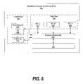
- FIG. 6illustrates an information handling system, which is a simplified example of a computer system capable of performing the computing operations described herein.
- Broadband processor architecture (BPA) 600includes a plurality of heterogeneous processors, a common memory, and a common bus.
- the heterogeneous processorsare processors with different instruction sets that share the common memory and the common bus.
- one of the heterogeneous processorsmay be a digital signal processor and the other heterogeneous processor may be a microprocessor, both sharing the same memory space.
- BPA 600sends and receives information to/from external devices through input output 670 , and distributes the information to control plane 610 and data plane 640 using processor element bus 660 .
- Control plane 610manages BPA 600 and distributes work to data plane 640 .
- Control plane 610includes processing unit 620 , which runs operating system (OS) 625 .
- processing unit 620may be a Power PC core that is embedded in BPA 600 and OS 625 may be a Linux operating system.
- Processing unit 620manages a common memory map table for BPA 600 .
- the memory map tablecorresponds to memory locations included in BPA 600 , such as L2 memory 630 as well as non-private memory included in data plane 640 .
- Data plane 640includes Synergistic Processing Complex's (SPC) 645 , 650 , and 655 .
- SPCSynergistic Processing Complex's
- Each SPCis used to process data information and each SPC may have different instruction sets.
- BPA 600may be used in a wireless communications system and each SPC may be responsible for separate processing tasks, such as modulation, chip rate processing, encoding, and network interfacing.
- each SPCmay have identical instruction sets and may be used in parallel to perform operations benefiting from parallel processes.
- Each SPCincludes a synergistic processing unit (SPU).
- An SPUis preferably a single instruction, multiple data (SIMD) processor, such as a digital signal processor, a microcontroller, a microprocessor, or a combination of these cores.
- SIMDsingle instruction, multiple data
- each SPUincludes a local memory, registers, four floating-point units, and four integer units. However, depending upon the processing power required, a greater or lesser number of floating points units
- SPC 645 , 650 , and 655are connected to processor element bus 660 , which passes information between control plane 610 , data plane 640 , and input/output 670 .
- Bus 660is an on-chip coherent multi-processor bus that passes information between I/O 670 , control plane 610 , and data plane 640 .
- Input/output 670includes flexible input-output logic, which dynamically assigns interface pins to input output controllers based upon peripheral devices that are connected to BPA 600 .
- FIG. 7illustrates information handling system 701 , which is a simplified example of a computer system capable of performing the computing operations described herein.
- Information handling system 701includes processor 700 which is coupled to host bus 702 .
- a level two (L2) cache memory 704is also coupled to host bus 702 .
- Host-to-PCI bridge 706is coupled to main memory 708 , includes cache memory and main memory control functions, and provides bus control to handle transfers among PCI bus 710 , processor 700 , L2 cache 704 , main memory 708 , and host bus 702 .
- Main memory 708is coupled to Host-to-PCI bridge 706 as well as host bus 702 .
- PCI bus 710Devices used solely by host processor(s) 700 , such as LAN card 730 , are coupled to PCI bus 710 .
- Service Processor Interface and ISA Access Pass-through 712provides an interface between PCI bus 710 and PCI bus 714 .
- PCI bus 714is insulated from PCI bus 710 .
- Devices, such as flash memory 718are coupled to PCI bus 714 .
- flash memory 718includes BIOS code that incorporates the necessary processor executable code for a variety of low-level system functions and system boot functions.
- PCI bus 714provides an interface for a variety of devices that are shared by host processor(s) 700 and Service Processor 716 including, for example, flash memory 718 .
- PCI-to-ISA bridge 735provides bus control to handle transfers between PCI bus 714 and ISA bus 740 , universal serial bus (USB) functionality 745 , power management functionality 755 , and can include other functional elements not shown, such as a real-time clock (RTC), DMA control, interrupt support, and system management bus support.
- RTCreal-time clock
- Nonvolatile RAM 720is attached to ISA Bus 740 .
- Service Processor 716includes JTAG and I2C busses 722 for communication with processor(s) 700 during initialization steps.
- JTAG/I2C busses 722are also coupled to L2 cache 704 , Host-to-PCI bridge 706 , and main memory 708 providing a communications path between the processor, the Service Processor, the L2 cache, the Host-to-PCI bridge, and the main memory.
- Service Processor 716also has access to system power resources for powering down information handling device 701 .
- Peripheral devices and input/output (I/O) devicescan be attached to various interfaces (e.g., parallel interface 762 , serial interface 764 , keyboard interface 768 , and mouse interface 770 coupled to ISA bus 740 .
- I/O devicescan be accommodated by a super I/O controller (not shown) attached to ISA bus 740 .
- LAN card 730is coupled to PCI bus 710 .
- modem 775is connected to serial port 764 and PCI-to-ISA Bridge 735 .
- FIGS. 6 and 7While the computer system described in FIGS. 6 and 7 is capable of executing the processes described herein, this computer system is simply one example of a computer system. Those skilled in the art will appreciate that many other computer system designs are capable of performing the processes described herein.
- One of the preferred implementations of the inventionis a client application, namely, a set of instructions (program code) in a code module that may, for example, be resident in the random access memory of the computer.
- the set of instructionsmay be stored in another computer memory, for example, in a hard disk drive, or in a removable memory such as an optical disk (for eventual use in a CD ROM) or floppy disk (for eventual use in a floppy disk drive), or downloaded via the Internet or other computer network.
- the present inventionmay be implemented as a computer program product for use in a computer.
Landscapes
- Engineering & Computer Science (AREA)
- Theoretical Computer Science (AREA)
- Physics & Mathematics (AREA)
- General Engineering & Computer Science (AREA)
- General Physics & Mathematics (AREA)
- Software Systems (AREA)
- Advance Control (AREA)
- Power Sources (AREA)
Abstract
Description
- 1) ERAT miss: When a processor's fetch unit encounters an ERAT miss, and stops fetching instructions until the translation for the ERAT miss is put into the ERAT.
- 2) Cache miss: When a fetch unit misses an instruction in the instruction cache, and stops fetching until the fetch data returns from secondary memory.
- 3) Data dependency: When a decode unit identifies an instruction's source registers match with older instructions that are still outstanding, and stops issuing the instruction until the depended data is available.
- 4) Non-pipeline instructions: Some floating-point instructions are non-pipeline instructions, which stall the pipeline when there is a floating-point instruction that is next to issue.
- 5) Context synchronizing instruction (CSI): CSI instructions, such as “Sync,” stall the pipeline until older instructions are complete.
Claims (7)
Priority Applications (5)
| Application Number | Priority Date | Filing Date | Title |
|---|---|---|---|
| US11/236,657US7401242B2 (en) | 2005-09-27 | 2005-09-27 | Dynamic power management in a processor design |
| EP06793427AEP1941338A2 (en) | 2005-09-27 | 2006-09-11 | System and method for dynamic power management in a processor design |
| CN2006800341885ACN101268432B (en) | 2005-09-27 | 2006-09-11 | System and method for dynamic power management in processor design |
| PCT/EP2006/066249WO2007039412A2 (en) | 2005-09-27 | 2006-09-11 | System and method for dynamic power management in a processor design |
| US12/130,736US7681056B2 (en) | 2005-09-27 | 2008-05-30 | Dynamic power management in a processor design |
Applications Claiming Priority (1)
| Application Number | Priority Date | Filing Date | Title |
|---|---|---|---|
| US11/236,657US7401242B2 (en) | 2005-09-27 | 2005-09-27 | Dynamic power management in a processor design |
Related Child Applications (1)
| Application Number | Title | Priority Date | Filing Date |
|---|---|---|---|
| US12/130,736ContinuationUS7681056B2 (en) | 2005-09-27 | 2008-05-30 | Dynamic power management in a processor design |
Publications (2)
| Publication Number | Publication Date |
|---|---|
| US20070074059A1 US20070074059A1 (en) | 2007-03-29 |
| US7401242B2true US7401242B2 (en) | 2008-07-15 |
Family
ID=37459347
Family Applications (2)
| Application Number | Title | Priority Date | Filing Date |
|---|---|---|---|
| US11/236,657Active2026-10-11US7401242B2 (en) | 2005-09-27 | 2005-09-27 | Dynamic power management in a processor design |
| US12/130,736Expired - LifetimeUS7681056B2 (en) | 2005-09-27 | 2008-05-30 | Dynamic power management in a processor design |
Family Applications After (1)
| Application Number | Title | Priority Date | Filing Date |
|---|---|---|---|
| US12/130,736Expired - LifetimeUS7681056B2 (en) | 2005-09-27 | 2008-05-30 | Dynamic power management in a processor design |
Country Status (4)
| Country | Link |
|---|---|
| US (2) | US7401242B2 (en) |
| EP (1) | EP1941338A2 (en) |
| CN (1) | CN101268432B (en) |
| WO (1) | WO2007039412A2 (en) |
Cited By (15)
| Publication number | Priority date | Publication date | Assignee | Title |
|---|---|---|---|---|
| US20080034311A1 (en)* | 2006-08-01 | 2008-02-07 | Raul Aguaviva | Method and system for debugging a graphics pipeline subunit |
| US20080030511A1 (en)* | 2006-08-01 | 2008-02-07 | Raul Aguaviva | Method and user interface for enhanced graphical operation organization |
| US20080229078A1 (en)* | 2005-09-27 | 2008-09-18 | International Business Machines Corporation | Dynamic Power Management in a Processor Design |
| US20090096797A1 (en)* | 2007-10-11 | 2009-04-16 | Qualcomm Incorporated | Demand based power control in a graphics processing unit |
| US20090259862A1 (en)* | 2008-04-10 | 2009-10-15 | Nvidia Corporation | Clock-gated series-coupled data processing modules |
| US20100169654A1 (en)* | 2006-03-01 | 2010-07-01 | Nvidia Corporation | Method for author verification and software authorization |
| US7891012B1 (en) | 2006-03-01 | 2011-02-15 | Nvidia Corporation | Method and computer-usable medium for determining the authorization status of software |
| US8436870B1 (en) | 2006-08-01 | 2013-05-07 | Nvidia Corporation | User interface and method for graphical processing analysis |
| US8701091B1 (en) | 2005-12-15 | 2014-04-15 | Nvidia Corporation | Method and system for providing a generic console interface for a graphics application |
| US20140115360A1 (en)* | 2011-10-25 | 2014-04-24 | Huawei Technologies Co., Ltd. | Method for Reducing Dynamic Power Consumption and Electronic Device |
| US8850371B2 (en) | 2012-09-14 | 2014-09-30 | Nvidia Corporation | Enhanced clock gating in retimed modules |
| US8963932B1 (en)* | 2006-08-01 | 2015-02-24 | Nvidia Corporation | Method and apparatus for visualizing component workloads in a unified shader GPU architecture |
| US9323315B2 (en) | 2012-08-15 | 2016-04-26 | Nvidia Corporation | Method and system for automatic clock-gating of a clock grid at a clock source |
| US9471456B2 (en) | 2013-05-15 | 2016-10-18 | Nvidia Corporation | Interleaved instruction debugger |
| US9645635B2 (en)* | 2015-05-26 | 2017-05-09 | Nvidia Corporation | Selective power gating to extend the lifetime of sleep FETs |
Families Citing this family (8)
| Publication number | Priority date | Publication date | Assignee | Title |
|---|---|---|---|---|
| DE102006004346A1 (en)* | 2006-01-30 | 2007-10-18 | Deutsche Thomson-Brandt Gmbh | Data bus interface with switch-off clock |
| US8073669B2 (en)* | 2007-08-21 | 2011-12-06 | International Business Machines Corporation | Method and apparatus for detecting clock gating opportunities in a pipelined electronic circuit design |
| CN101493761B (en)* | 2008-01-25 | 2013-05-29 | 国际商业机器公司 | Processor pipeline processing instruction method and corresponding processor |
| CN103890713B (en)* | 2011-10-01 | 2018-08-24 | 英特尔公司 | Device and method for managing the register information in processing system |
| GB2547914B (en)* | 2016-03-02 | 2018-05-09 | Advanced Risc Mach Ltd | Data processing systems |
| CN107610039A (en)* | 2016-07-12 | 2018-01-19 | 联发科技股份有限公司 | Image processing method and image processing apparatus |
| US10877670B1 (en) | 2016-11-28 | 2020-12-29 | Barefoot Networks, Inc. | Dynamically reconfiguring data plane of forwarding element to adjust data plane throughput based on detected conditions |
| US10630294B1 (en)* | 2019-03-04 | 2020-04-21 | Micron Technology, Inc. | Apparatuses and methods for transmitting an operation mode with a clock |
Citations (12)
| Publication number | Priority date | Publication date | Assignee | Title |
|---|---|---|---|---|
| US5203003A (en)* | 1991-03-28 | 1993-04-13 | Echelon Corporation | Computer architecture for conserving power by using shared resources and method for suspending processor execution in pipeline |
| US5918042A (en)* | 1996-02-29 | 1999-06-29 | Arm Limited | Dynamic logic pipeline control |
| US6247134B1 (en)* | 1999-03-31 | 2001-06-12 | Synopsys, Inc. | Method and system for pipe stage gating within an operating pipelined circuit for power savings |
| US20020138777A1 (en)* | 2001-03-21 | 2002-09-26 | Apple Computer Inc. | Method and apparatus for saving power in pipelined processors |
| US6513057B1 (en)* | 1996-10-28 | 2003-01-28 | Unisys Corporation | Heterogeneous symmetric multi-processing system |
| US6609209B1 (en)* | 1999-12-29 | 2003-08-19 | Intel Corporation | Method and apparatus for reducing the power consumed by a processor by gating the clock signal to pipeline stages |
| US6611920B1 (en)* | 2000-01-21 | 2003-08-26 | Intel Corporation | Clock distribution system for selectively enabling clock signals to portions of a pipelined circuit |
| US6636976B1 (en)* | 2000-06-30 | 2003-10-21 | Intel Corporation | Mechanism to control di/dt for a microprocessor |
| US20040068640A1 (en)* | 2002-10-02 | 2004-04-08 | International Business Machines Corporation | Interlocked synchronous pipeline clock gating |
| US6906554B1 (en)* | 2003-12-16 | 2005-06-14 | Faraday Technology Corp. | Pipeline-based circuit with a postponed clock-gating mechanism for reducing power consumption and related driving method thereof |
| US6948050B1 (en)* | 1989-11-17 | 2005-09-20 | Texas Instruments Incorporated | Single integrated circuit embodying a dual heterogenous processors with separate instruction handling hardware |
| US7266708B2 (en)* | 2004-10-12 | 2007-09-04 | Via Technologies, Inc. | System for idling a processor pipeline wherein the fetch stage comprises a multiplexer for outputting NOP that forwards an idle signal through the pipeline |
Family Cites Families (11)
| Publication number | Priority date | Publication date | Assignee | Title |
|---|---|---|---|---|
| US5783958A (en)* | 1996-01-19 | 1998-07-21 | Sgs-Thomson Microelectronics, Inc. | Switching master slave circuit |
| JP3406790B2 (en)* | 1996-11-25 | 2003-05-12 | 株式会社東芝 | Data transfer system and data transfer method |
| US5987620A (en)* | 1997-09-19 | 1999-11-16 | Thang Tran | Method and apparatus for a self-timed and self-enabled distributed clock |
| US6304125B1 (en)* | 1998-09-04 | 2001-10-16 | Sun Microsystems, Inc. | Method for generating and distribution of polyphase clock signals |
| US6629250B2 (en)* | 1999-04-23 | 2003-09-30 | Cray Inc. | Adjustable data delay using programmable clock shift |
| US6651176B1 (en)* | 1999-12-08 | 2003-11-18 | Hewlett-Packard Development Company, L.P. | Systems and methods for variable control of power dissipation in a pipelined processor |
| US6393579B1 (en)* | 1999-12-21 | 2002-05-21 | Intel Corporation | Method and apparatus for saving power and improving performance in a collapsable pipeline using gated clocks |
| US6553473B1 (en)* | 2000-03-30 | 2003-04-22 | Ip-First, Llc | Byte-wise tracking on write allocate |
| WO2002021323A2 (en)* | 2000-09-08 | 2002-03-14 | Avaz Networks | Hardware function generator support in a dsp |
| US6822481B1 (en)* | 2003-06-12 | 2004-11-23 | Agilent Technologies, Inc. | Method and apparatus for clock gating clock trees to reduce power dissipation |
| US7401242B2 (en)* | 2005-09-27 | 2008-07-15 | International Business Machines Corporation | Dynamic power management in a processor design |
- 2005
- 2005-09-27USUS11/236,657patent/US7401242B2/enactiveActive
- 2006
- 2006-09-11EPEP06793427Apatent/EP1941338A2/ennot_activeWithdrawn
- 2006-09-11CNCN2006800341885Apatent/CN101268432B/ennot_activeExpired - Fee Related
- 2006-09-11WOPCT/EP2006/066249patent/WO2007039412A2/enactiveApplication Filing
- 2008
- 2008-05-30USUS12/130,736patent/US7681056B2/ennot_activeExpired - Lifetime
Patent Citations (12)
| Publication number | Priority date | Publication date | Assignee | Title |
|---|---|---|---|---|
| US6948050B1 (en)* | 1989-11-17 | 2005-09-20 | Texas Instruments Incorporated | Single integrated circuit embodying a dual heterogenous processors with separate instruction handling hardware |
| US5203003A (en)* | 1991-03-28 | 1993-04-13 | Echelon Corporation | Computer architecture for conserving power by using shared resources and method for suspending processor execution in pipeline |
| US5918042A (en)* | 1996-02-29 | 1999-06-29 | Arm Limited | Dynamic logic pipeline control |
| US6513057B1 (en)* | 1996-10-28 | 2003-01-28 | Unisys Corporation | Heterogeneous symmetric multi-processing system |
| US6247134B1 (en)* | 1999-03-31 | 2001-06-12 | Synopsys, Inc. | Method and system for pipe stage gating within an operating pipelined circuit for power savings |
| US6609209B1 (en)* | 1999-12-29 | 2003-08-19 | Intel Corporation | Method and apparatus for reducing the power consumed by a processor by gating the clock signal to pipeline stages |
| US6611920B1 (en)* | 2000-01-21 | 2003-08-26 | Intel Corporation | Clock distribution system for selectively enabling clock signals to portions of a pipelined circuit |
| US6636976B1 (en)* | 2000-06-30 | 2003-10-21 | Intel Corporation | Mechanism to control di/dt for a microprocessor |
| US20020138777A1 (en)* | 2001-03-21 | 2002-09-26 | Apple Computer Inc. | Method and apparatus for saving power in pipelined processors |
| US20040068640A1 (en)* | 2002-10-02 | 2004-04-08 | International Business Machines Corporation | Interlocked synchronous pipeline clock gating |
| US6906554B1 (en)* | 2003-12-16 | 2005-06-14 | Faraday Technology Corp. | Pipeline-based circuit with a postponed clock-gating mechanism for reducing power consumption and related driving method thereof |
| US7266708B2 (en)* | 2004-10-12 | 2007-09-04 | Via Technologies, Inc. | System for idling a processor pipeline wherein the fetch stage comprises a multiplexer for outputting NOP that forwards an idle signal through the pipeline |
Cited By (22)
| Publication number | Priority date | Publication date | Assignee | Title |
|---|---|---|---|---|
| US20080229078A1 (en)* | 2005-09-27 | 2008-09-18 | International Business Machines Corporation | Dynamic Power Management in a Processor Design |
| US7681056B2 (en)* | 2005-09-27 | 2010-03-16 | International Business Machines Corporation | Dynamic power management in a processor design |
| US8701091B1 (en) | 2005-12-15 | 2014-04-15 | Nvidia Corporation | Method and system for providing a generic console interface for a graphics application |
| US7891012B1 (en) | 2006-03-01 | 2011-02-15 | Nvidia Corporation | Method and computer-usable medium for determining the authorization status of software |
| US8452981B1 (en) | 2006-03-01 | 2013-05-28 | Nvidia Corporation | Method for author verification and software authorization |
| US8966272B2 (en) | 2006-03-01 | 2015-02-24 | Nvidia Corporation | Method for author verification and software authorization |
| US20100169654A1 (en)* | 2006-03-01 | 2010-07-01 | Nvidia Corporation | Method for author verification and software authorization |
| US8436870B1 (en) | 2006-08-01 | 2013-05-07 | Nvidia Corporation | User interface and method for graphical processing analysis |
| US8436864B2 (en) | 2006-08-01 | 2013-05-07 | Nvidia Corporation | Method and user interface for enhanced graphical operation organization |
| US8963932B1 (en)* | 2006-08-01 | 2015-02-24 | Nvidia Corporation | Method and apparatus for visualizing component workloads in a unified shader GPU architecture |
| US20080034311A1 (en)* | 2006-08-01 | 2008-02-07 | Raul Aguaviva | Method and system for debugging a graphics pipeline subunit |
| US8607151B2 (en) | 2006-08-01 | 2013-12-10 | Nvidia Corporation | Method and system for debugging a graphics pipeline subunit |
| US20080030511A1 (en)* | 2006-08-01 | 2008-02-07 | Raul Aguaviva | Method and user interface for enhanced graphical operation organization |
| US20090096797A1 (en)* | 2007-10-11 | 2009-04-16 | Qualcomm Incorporated | Demand based power control in a graphics processing unit |
| US8458497B2 (en) | 2007-10-11 | 2013-06-04 | Qualcomm Incorporated | Demand based power control in a graphics processing unit |
| US8448002B2 (en)* | 2008-04-10 | 2013-05-21 | Nvidia Corporation | Clock-gated series-coupled data processing modules |
| US20090259862A1 (en)* | 2008-04-10 | 2009-10-15 | Nvidia Corporation | Clock-gated series-coupled data processing modules |
| US20140115360A1 (en)* | 2011-10-25 | 2014-04-24 | Huawei Technologies Co., Ltd. | Method for Reducing Dynamic Power Consumption and Electronic Device |
| US9323315B2 (en) | 2012-08-15 | 2016-04-26 | Nvidia Corporation | Method and system for automatic clock-gating of a clock grid at a clock source |
| US8850371B2 (en) | 2012-09-14 | 2014-09-30 | Nvidia Corporation | Enhanced clock gating in retimed modules |
| US9471456B2 (en) | 2013-05-15 | 2016-10-18 | Nvidia Corporation | Interleaved instruction debugger |
| US9645635B2 (en)* | 2015-05-26 | 2017-05-09 | Nvidia Corporation | Selective power gating to extend the lifetime of sleep FETs |
Also Published As
| Publication number | Publication date |
|---|---|
| US7681056B2 (en) | 2010-03-16 |
| EP1941338A2 (en) | 2008-07-09 |
| CN101268432A (en) | 2008-09-17 |
| US20080229078A1 (en) | 2008-09-18 |
| WO2007039412A2 (en) | 2007-04-12 |
| WO2007039412A3 (en) | 2007-10-04 |
| US20070074059A1 (en) | 2007-03-29 |
| CN101268432B (en) | 2010-06-16 |
Similar Documents
| Publication | Publication Date | Title |
|---|---|---|
| US7681056B2 (en) | Dynamic power management in a processor design | |
| US7913070B2 (en) | Time-of-life counter for handling instruction flushes from a queue | |
| US9201801B2 (en) | Computing device with asynchronous auxiliary execution unit | |
| TWI742032B (en) | Methods, apparatus, and instructions for user-level thread suspension | |
| TWI494850B (en) | Providing an asymmetric multicore processor system transparently to an operating system | |
| JP5047542B2 (en) | Method, computer program, and apparatus for blocking threads when dispatching a multithreaded processor (fine multithreaded dispatch lock mechanism) | |
| US7809933B2 (en) | System and method for optimizing branch logic for handling hard to predict indirect branches | |
| KR102262176B1 (en) | Avoiding premature enabling of nonmaskable interrupts when returning from exceptions | |
| US8145887B2 (en) | Enhanced load lookahead prefetch in single threaded mode for a simultaneous multithreaded microprocessor | |
| TW201508635A (en) | Dynamic reconfiguration of multi-core processor | |
| US9552039B2 (en) | Constrained boot techniques in multi-core platforms | |
| US9323315B2 (en) | Method and system for automatic clock-gating of a clock grid at a clock source | |
| KR20070054096A (en) | System and method for dynamically selecting how to perform the save command | |
| US10761854B2 (en) | Preventing hazard flushes in an instruction sequencing unit of a multi-slice processor | |
| US20040215982A1 (en) | System and method for electrical power management in a data processing system | |
| JP2013546036A (en) | Processor power management based on instruction class and content | |
| US20230118408A1 (en) | Fault Isolation and Recovery of CPU Cores for Failed Secondary Asymmetric Multiprocessing Instance | |
| US5726921A (en) | Floating point power conservation | |
| US6584573B1 (en) | Placing a computer system into a sleeping state | |
| EP0901063A2 (en) | Power management methods | |
| US20080148021A1 (en) | High Frequency Stall Design | |
| US20060230316A1 (en) | Method ensuring normal operation at early power-on self test stage | |
| US7861064B2 (en) | Method, system, and computer program product for selectively accelerating early instruction processing | |
| US20230195981A1 (en) | Hazard generating for speculative cores in a microprocessor | |
| US20090077322A1 (en) | System and Method for Getllar Hit Cache Line Data Forward Via Data-Only Transfer Protocol Through BEB Bus |
Legal Events
| Date | Code | Title | Description |
|---|---|---|---|
| AS | Assignment | Owner name:GERHARDT, DIANA R., TEXAS Free format text:ASSIGNMENT OF ASSIGNORS INTEREST;ASSIGNORS:ABERNATHY, CHRISTOPHER MICHAEL;DEMENT, JONATHAN JAMES;HALL, RONALD P.;AND OTHERS;REEL/FRAME:016680/0684;SIGNING DATES FROM 20050901 TO 20050915 | |
| FEPP | Fee payment procedure | Free format text:PAYOR NUMBER ASSIGNED (ORIGINAL EVENT CODE: ASPN); ENTITY STATUS OF PATENT OWNER: LARGE ENTITY | |
| STCF | Information on status: patent grant | Free format text:PATENTED CASE | |
| AS | Assignment | Owner name:INTERNATIONAL BUSINESS MACHINES CORPORATION, NEW Y Free format text:ASSIGNMENT OF ASSIGNORS INTEREST;ASSIGNORS:ABERNATHY, CHRISTOPHER MICHAEL;DEMENT, JONATHAN JAMES;HALL, RONALD P;AND OTHERS;SIGNING DATES FROM 20050901 TO 20050915;REEL/FRAME:027747/0302 | |
| REMI | Maintenance fee reminder mailed | ||
| AS | Assignment | Owner name:FACEBOOK, INC., CALIFORNIA Free format text:ASSIGNMENT OF ASSIGNORS INTEREST;ASSIGNOR:INTERNATIONAL BUSINESS MACHINES CORPORATION;REEL/FRAME:027991/0435 Effective date:20120327 | |
| FPAY | Fee payment | Year of fee payment:4 | |
| SULP | Surcharge for late payment | ||
| FPAY | Fee payment | Year of fee payment:8 | |
| MAFP | Maintenance fee payment | Free format text:PAYMENT OF MAINTENANCE FEE, 12TH YEAR, LARGE ENTITY (ORIGINAL EVENT CODE: M1553); ENTITY STATUS OF PATENT OWNER: LARGE ENTITY Year of fee payment:12 | |
| AS | Assignment | Owner name:META PLATFORMS, INC., CALIFORNIA Free format text:CHANGE OF NAME;ASSIGNOR:FACEBOOK, INC.;REEL/FRAME:058553/0802 Effective date:20211028 |