US7400856B2 - Method and apparatus for relay facilitated communications - Google Patents
Method and apparatus for relay facilitated communicationsDownload PDFInfo
- Publication number
- US7400856B2 US7400856B2US10/654,227US65422703AUS7400856B2US 7400856 B2US7400856 B2US 7400856B2US 65422703 AUS65422703 AUS 65422703AUS 7400856 B2US7400856 B2US 7400856B2
- Authority
- US
- United States
- Prior art keywords
- transmitter
- transmission
- wireless
- relay resource
- base site
- Prior art date
- Legal status (The legal status is an assumption and is not a legal conclusion. Google has not performed a legal analysis and makes no representation as to the accuracy of the status listed.)
- Expired - Lifetime
Links
- 238000004891communicationMethods0.000titleclaimsabstractdescription87
- 238000000034methodMethods0.000titleclaimsdescription62
- 230000005540biological transmissionEffects0.000claimsdescription248
- 230000000694effectsEffects0.000claimsdescription14
- 238000012545processingMethods0.000claimsdescription10
- 239000012190activatorSubstances0.000claimsdescription7
- 238000013468resource allocationMethods0.000claimsdescription7
- 230000002123temporal effectEffects0.000claimsdescription6
- 230000004044responseEffects0.000claimsdescription5
- 230000003213activating effectEffects0.000claims1
- 230000008569processEffects0.000description26
- 238000013459approachMethods0.000description10
- 238000010586diagramMethods0.000description10
- 230000011664signalingEffects0.000description7
- 230000009471actionEffects0.000description6
- 230000004075alterationEffects0.000description2
- 230000006870functionEffects0.000description2
- 230000004048modificationEffects0.000description2
- 238000012986modificationMethods0.000description2
- 239000013589supplementSubstances0.000description2
- 230000002730additional effectEffects0.000description1
- 230000008901benefitEffects0.000description1
- 230000008859changeEffects0.000description1
- 238000013461designMethods0.000description1
- 238000001514detection methodMethods0.000description1
- 230000004069differentiationEffects0.000description1
- 230000009365direct transmissionEffects0.000description1
- 230000007717exclusionEffects0.000description1
- 238000005562fadingMethods0.000description1
- 230000001771impaired effectEffects0.000description1
- 230000006872improvementEffects0.000description1
- 230000001939inductive effectEffects0.000description1
- 230000007246mechanismEffects0.000description1
- 230000037361pathwayEffects0.000description1
- 238000012913prioritisationMethods0.000description1
- 230000000717retained effectEffects0.000description1
- 230000007480spreadingEffects0.000description1
- 230000001960triggered effectEffects0.000description1
Images


Classifications
- H—ELECTRICITY
- H04—ELECTRIC COMMUNICATION TECHNIQUE
- H04W—WIRELESS COMMUNICATION NETWORKS
- H04W88/00—Devices specially adapted for wireless communication networks, e.g. terminals, base stations or access point devices
- H04W88/02—Terminal devices
- H04W88/04—Terminal devices adapted for relaying to or from another terminal or user
- H—ELECTRICITY
- H04—ELECTRIC COMMUNICATION TECHNIQUE
- H04W—WIRELESS COMMUNICATION NETWORKS
- H04W72/00—Local resource management
- H04W72/04—Wireless resource allocation
- H—ELECTRICITY
- H04—ELECTRIC COMMUNICATION TECHNIQUE
- H04B—TRANSMISSION
- H04B7/00—Radio transmission systems, i.e. using radiation field
- H04B7/24—Radio transmission systems, i.e. using radiation field for communication between two or more posts
- H04B7/26—Radio transmission systems, i.e. using radiation field for communication between two or more posts at least one of which is mobile
- H04B7/2603—Arrangements for wireless physical layer control
- H04B7/2606—Arrangements for base station coverage control, e.g. by using relays in tunnels
- H—ELECTRICITY
- H04—ELECTRIC COMMUNICATION TECHNIQUE
- H04L—TRANSMISSION OF DIGITAL INFORMATION, e.g. TELEGRAPHIC COMMUNICATION
- H04L1/00—Arrangements for detecting or preventing errors in the information received
- H04L1/12—Arrangements for detecting or preventing errors in the information received by using return channel
- H04L1/16—Arrangements for detecting or preventing errors in the information received by using return channel in which the return channel carries supervisory signals, e.g. repetition request signals
- H04L1/18—Automatic repetition systems, e.g. Van Duuren systems
- H04L1/1867—Arrangements specially adapted for the transmitter end
- H—ELECTRICITY
- H04—ELECTRIC COMMUNICATION TECHNIQUE
- H04W—WIRELESS COMMUNICATION NETWORKS
- H04W72/00—Local resource management
- H04W72/50—Allocation or scheduling criteria for wireless resources
- H04W72/54—Allocation or scheduling criteria for wireless resources based on quality criteria
- H—ELECTRICITY
- H04—ELECTRIC COMMUNICATION TECHNIQUE
- H04W—WIRELESS COMMUNICATION NETWORKS
- H04W84/00—Network topologies
- H04W84/02—Hierarchically pre-organised networks, e.g. paging networks, cellular networks, WLAN [Wireless Local Area Network] or WLL [Wireless Local Loop]
- H04W84/04—Large scale networks; Deep hierarchical networks
- H04W84/042—Public Land Mobile systems, e.g. cellular systems
- H04W84/047—Public Land Mobile systems, e.g. cellular systems using dedicated repeater stations
- H—ELECTRICITY
- H04—ELECTRIC COMMUNICATION TECHNIQUE
- H04W—WIRELESS COMMUNICATION NETWORKS
- H04W88/00—Devices specially adapted for wireless communication networks, e.g. terminals, base stations or access point devices
- H04W88/08—Access point devices
- H—ELECTRICITY
- H04—ELECTRIC COMMUNICATION TECHNIQUE
- H04B—TRANSMISSION
- H04B7/00—Radio transmission systems, i.e. using radiation field
- H04B7/14—Relay systems
- H04B7/15—Active relay systems
- H04B7/155—Ground-based stations
- H04B7/15528—Control of operation parameters of a relay station to exploit the physical medium
- H04B7/15542—Selecting at relay station its transmit and receive resources
- H—ELECTRICITY
- H04—ELECTRIC COMMUNICATION TECHNIQUE
- H04L—TRANSMISSION OF DIGITAL INFORMATION, e.g. TELEGRAPHIC COMMUNICATION
- H04L1/00—Arrangements for detecting or preventing errors in the information received
- H04L2001/0092—Error control systems characterised by the topology of the transmission link
- H04L2001/0097—Relays
- H—ELECTRICITY
- H04—ELECTRIC COMMUNICATION TECHNIQUE
- H04W—WIRELESS COMMUNICATION NETWORKS
- H04W16/00—Network planning, e.g. coverage or traffic planning tools; Network deployment, e.g. resource partitioning or cells structures
- H04W16/24—Cell structures
- H04W16/26—Cell enhancers or enhancement, e.g. for tunnels, building shadow
- H—ELECTRICITY
- H04—ELECTRIC COMMUNICATION TECHNIQUE
- H04W—WIRELESS COMMUNICATION NETWORKS
- H04W88/00—Devices specially adapted for wireless communication networks, e.g. terminals, base stations or access point devices
- H04W88/08—Access point devices
- H04W88/085—Access point devices with remote components
- Y—GENERAL TAGGING OF NEW TECHNOLOGICAL DEVELOPMENTS; GENERAL TAGGING OF CROSS-SECTIONAL TECHNOLOGIES SPANNING OVER SEVERAL SECTIONS OF THE IPC; TECHNICAL SUBJECTS COVERED BY FORMER USPC CROSS-REFERENCE ART COLLECTIONS [XRACs] AND DIGESTS
- Y02—TECHNOLOGIES OR APPLICATIONS FOR MITIGATION OR ADAPTATION AGAINST CLIMATE CHANGE
- Y02D—CLIMATE CHANGE MITIGATION TECHNOLOGIES IN INFORMATION AND COMMUNICATION TECHNOLOGIES [ICT], I.E. INFORMATION AND COMMUNICATION TECHNOLOGIES AIMING AT THE REDUCTION OF THEIR OWN ENERGY USE
- Y02D30/00—Reducing energy consumption in communication networks
- Y02D30/70—Reducing energy consumption in communication networks in wireless communication networks
Definitions
- This inventionrelates generally to wireless communications and more particularly to the use of communication relays.
- Wireless communication systemsare known in the art.
- remote communication units(at least some of which may be mobile) communicate with one another and/or with others via system infrastructure such as fixed-location transmitters and receivers.
- system infrastructuresuch as fixed-location transmitters and receivers.
- wireless communication systemsare characterized by a corresponding communication range (typically characterized by either or both of a transmission range and a reception range) beyond which the wireless communications capability of the system infrastructure cannot usefully extend.
- Repeatersare also known in the art. Such devices typically serve to extend the communication range of a given communication system (by extending the transmission and/or reception range). Via this mechanism, for example, a relatively low power remote communication unit can effectively communicate with a relatively distant system receiver notwithstanding that the remote communication unit is otherwise out-of-range of the distant system receiver. Such repeaters often operate in an autonomous automatic mode and repeat whatever transmissions they successfully receive.
- FIG. 1comprises a diagrammatic system overview as configured in accordance with various embodiments of the invention
- FIG. 2comprises a block diagram illustrating various communication links as configured in accordance with various embodiments of the invention
- FIG. 3comprises an illustrative block diagram of a base site as configured in accordance with various embodiments of the invention
- FIG. 4comprises a base site flow diagram as configured in accordance with various embodiments of the invention.
- FIG. 5comprises a relay resource flow diagram as configured in accordance with an embodiment of the invention
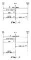
- FIG. 6comprises a timing diagram for a first example as configured in accordance with various embodiments of the invention.
- FIG. 7comprises a timing diagram for a second example as configured in accordance with various embodiments of the invention.
- FIG. 8comprises a timing diagram for a third example as configured in accordance with various embodiments of the invention.
- FIG. 9comprises a timing diagram for a fourth example as configured in accordance with various embodiments of the invention.
- FIG. 10comprises a timing diagram for a fifth example as configured in accordance with various embodiments of the invention.
- FIG. 11comprises a flow diagram for a sixth example as configured in accordance with an embodiment of the invention.
- a base sitedetermines a need to receive a wireless transmission from a transmitter that is presently within communications range of the base site and automatically determines whether to allocate a wireless relay resource to thereby at least attempt to increase a quality of service to support the wireless transmission from this transmitter.
- one or more relayscan be automatically utilized when and as appropriate to support, for example, the use of relatively high data rates by the transmitter.
- Such relayscan be configured in any number of ways consistent with this approach. For example, a given relay can simply forward, automatically, all received communications (or at least those communications that are received with a least a predetermined degree of acceptable reception) and the base site can effect its determination by automatically determining whether to accept such automatically relayed transmissions. As another example, a given relay can relay received transmissions only upon receipt of an enabling instruction from the base site. In either of the above examples, the relay can effect a concurrent relayed transmission or can effect a store-and-forward operation by delaying the relayed transmission until a later (typically predetermined) time or opportunity.
- Such relayscan also be used in conjunction with an ARQ process such as a hybrid ARQ process.
- a relaycan store received transmissions from a given remote communication device and only relay a given transmission (or portion thereof) in response to an ARQ request or error indicator from the base site.
- the relayitself can further effect a significant part of the ARQ process by storing multiple transmissions of a given data package or message and then combining those stored results to permit a proper decoding of the data package/message. The latter can then be relayed to the base site.
- a given base sitecan receive the relayed transmissions of one or more relays and utilize those relayed transmissions in combination with transmissions as are received by the base site from the remote communication unit to attempt to reconstruct an accurate version of the original transmission.
- a wireless communication systemwill typically have at least one base site 10 transceiver (in this embodiment, for the sake of simplicity and clarity, the base site 10 is presumed to serve essentially all of the relevant infrastructure functions described herein; it will of course be understood by those skilled in the art that such functionality can be distributed and/or otherwise parsed over one or more other architectural elements of a given communication system and that the expression “base site” as used herein shall be understood to refer in general to any and all presently known or hereafter developed corresponding communication system infrastructure elements and components).
- This base site 10serves, in part to source transmissions to remote units and to receive transmissions from such units.
- wireless communicationsare typically bounded by a communications range.
- the communication rangeis considered to be the set of all locations where a remote unit and the base site can establish a communication link with a data rate larger than a minimum predetermined data rate.
- the minimum predetermined data ratecan be the data rate necessary for a voice communication, or in another example the minimum predetermined data rate can be the data rate necessary for basic control signaling (such as access requests and grants). Since such a base site 10 can typically transmit with greater power (and often via use of one or more relatively tall and well-placed antenna platforms) than a typical remote unit, the transmit range of such a base site will usually be greater than the effective receive range 11 of the base site.
- a given base site 10may have no difficulty in transmitting information to both proximally located remote units (such as transmitter A 12 ) and to more distally located remote units (such as transmitter B 13 ).
- This same base site 10may not be able to reliably receive transmissions as sourced by the more distally located transmitter B 13 , as that transmitter is located beyond the effective reception range 11 of the base site 10 .
- Repeaterscan be used to extend this effective reception range 11 as is well understood by those skilled in the art. Such range extension, however, is not an essential point of these embodiments. Instead, these embodiments are directed more towards supporting a desired level of quality of service for a remote unit transmitter that is already within the reception communication range 11 of the base site 10 .
- FIG. 1illustrates three such relays 15 , 16 , and 17 though more or fewer can be utilized as appropriate. Although these embodiments are preferably for relays that are in fixed locations, it should be understood that such relays can be mobile as well. These relays will typically have at least a wireless receiver capability in order to compatibly receive remote unit transmissions and/or control signaling from the base site 10 . A relay may also have a wireline receiver capability to receive commands from the base site over a wireline link rather than a wireless link.
- these relayscan have a wireless and/or a wireline transmission capability to facilitate the provision of relayed transmissions to the base site 10 and/or an exchange of signaling with one or more of the remote units.
- Such wireless transmission capabilitycan be either in-band or out-of-band with respect to the communication resources that are used by the remote units to facilitate their own transmissions (when out-of-band, this can refer to both the physical carrier itself and/or a point of temporal/subchannel/code differentiation).
- a transmitter(such as transmitter C 14 ) that is otherwise within reception range 11 of a given base site 10 can benefit from one or more relay resources that can essentially serve to improve reception of the signal originating from the transmitter via better propagation conditions and/or transmit power and thereby permit a higher quality of service (such as but not limited to higher data transmission rates).
- a base site 10will often be able to transmit directly to a given remote unit 14 .
- These transmissions 21can include both control information (such as resource allocation messages and the like) and bearer data (such as voice or other user data to be provided to the remote unit 14 ).
- the remote unit 14can itself make direct transmissions 22 to the base site 10 (to provide, for example, access requests and/or bearer data).
- this inbound transmission linkmay not be of sufficient quality to permit a desired level of quality of service.
- the base site 10can also preferably transmit control information 23 to one or more relay resources (with two such relay resources 15 and 16 being shown in this illustration). Though not essential, such capability will facilitate dynamic flexibility with respect to the particular manner by which a base site 10 elects to utilize a given relay resource to effect provision of a desired level of quality of service for a given remote unit 14 .
- the relay resources 15 and 16are preferably configured to compatibly receive communications, such as bearer data 24 , as transmitted by a remote unit 14 .
- Such relay resourcescan be configured, if desired, to always receive such communications, or to only receive specific communications as assigned, for example, by the base site 10 via corresponding control signaling.
- these relay resources 15 and 16are preferably configured to relay 25 at least portions of the transmissions as received from the remote unit 14 .
- a given relay resourcecan be configured in any of a variety of ways in this regard to suit the specific needs and requirements of a given application.
- a given relay resourcecan automatically relay (either immediately or at a subsequent time) all received transmissions, or can automatically relay only those received transmissions that at least meet a predetermined (or dynamically established) reception criteria (such as received signal strength or bit error rate), or can only relay all or parts of received transmissions as may be specifically requested by, for example, the base site 10 .
- a predetermined (or dynamically established) reception criteriasuch as received signal strength or bit error rate
- a base site 10can utilize, in a variety of different ways, at least one relay resource to facilitate provision of a desired level of quality of service to support the communications of a remote unit that is already within effective reception range of the base site.
- a base site 10will preferably include, in addition to a wireless transceiver 31 and such other communications and control support platforms as may be appropriate to a given application (not shown as such functionality and their supporting platforms are well understood in the art), a resource allocator 32 to determine when to activate a relay resource to support, for example, a requested allocation of resources to facilitate the transmission of information to the base site.
- this resource allocator 32provides such determinations to an optional relay resource activator 33 that aids in controlling how the base site 10 will treat relayed transmissions as received at the base site 10 and/or to facilitate the provision of instructions to a given relay resource.
- these instructionswill serve to facilitate attainment of the desired quality of service level for the remote unit.
- such instructionscan include, but is not limited to, any of:
- such a relay resource activator 33can serve to substantially simultaneously activate a plurality of relay resources to facilitate attainment of a given level of desired quality of service as well as only a single relay resource.
- the base sitewill include a wireless transmitter and receiver along with a resource allocator that is operably coupled to the wireless transmitter and receiver and that is responsive to a wirelessly transmitted signal from a remote unit that is within reception range of the base site and that is requesting allocation of a communication resource to facilitate transmission of information to the base site.
- the base sitepreferably includes a relay resource activator that is operably coupled to the resource allocator, such that a relay resource can be activated by the communications controller to improve quality of service for a wireless transmission from the remote unit when transmitting within reception range of the base site.
- a base sitewill typically determine 41 a need to receive a wireless transmission from a transmitter that is presently within communications range of the base site.
- the base sitecan receive a wireless message from the transmitter that includes an indication of such a need to transmit (such a request can be communicated, for example, via a control channel).
- the process 40will then automatically determine 42 whether to allocate one or more relay resources to increase the quality of service that would otherwise be provided to support the requested transmission from the transmitter.
- a determinationcan include determining whether a present wireless communication path between the requesting transmitter and the base site will not likely support a given desired effective data rate.
- this determinationcan including using information regarding link channel quality for at least one transmission from the base site to the transmitter (as one example, the base site could consider the apparent link channel quality as pertained to reception by the base site of a message from the transmitter making requests as suggested above).
- this determination 42can be limited to determining whether to utilize a single relay resource (either from a solitary available relay resource or from a pool of candidate relay resources as may, or may not, be available in a given system). Or, if desired, this determination 42 can include determining whether to allocate two or more relay resources to support upgraded quality of service for the communication to be facilitated by the base site. In such a case, and again depending upon the needs of a given application, the base site can allocate some but not all presently available relay resources. In a preferred embodiment, when allocating some but not all presently available relay resources, the base site will identify specific relay resources to allocate in this manner. In a simpler embodiments, all the relays can be activated simultaneously.
- the base sitecould be configured to re-allocate an already-allocated relay resource to support the present communication in preference to an earlier allocation.
- a re-allocationcould be based on any of a variety of decision-making criteria including, but not limited to, relative priority levels of the remote units with respect to one another, relative prioritization of the supported communication service, a change in the traffic demand, and/or any other suitable and relevant standard.
- this determinationmay or can include a determination to allocate a relay resource that itself utilizes at least one carrier resource (such as, for example, a particular wireless link) that is otherwise also shared by the communication system that includes the base site to effect direct communications between the base site and member communication units (for example, the relay resource may utilize such a shared carrier resource to facilitate its own relayed transmissions).
- a relay resourcethat itself utilizes at least one carrier resource (such as, for example, a particular wireless link) that is otherwise also shared by the communication system that includes the base site to effect direct communications between the base site and member communication units (for example, the relay resource may utilize such a shared carrier resource to facilitate its own relayed transmissions).
- the relay resourcemay utilize such a shared carrier resource to facilitate its own relayed transmissions.
- this determinationmay or can include a determination to allocate a relay resource that utilizes at least one carrier resource (such as, but not limited to, a wireline link to the base site) that is not otherwise also shared by the communication system that includes the base site to effect direct communications between the base site and member communication units. In such a case, less care may be needed to ensure that resource-usage conflicts are avoided.
- a relay resourcethat utilizes at least one carrier resource (such as, but not limited to, a wireline link to the base site) that is not otherwise also shared by the communication system that includes the base site to effect direct communications between the base site and member communication units.
- this determination 42 to allocate a relay resourcecan vary, at least in part, with respect to the kind of relay resource that is available.
- the relay resourcemay be configured to automatically relay all received transmissions from remote units (or at least those received transmissions that meet at least a predetermined level of signal quality).
- the determination 42 to allocate the relay resourcemay be effected by the base site determining to accept relayed transmissions as are otherwise automatically sourced by such relay resources.
- the relay resource as allocated by the base sitemay comprise a relatively simple waveform processing relay resource.
- the relay resource as allocated by the base sitemay comprise a demodulation processing relay resource or a demodulation and decoding processing relay resource.
- the relaytransmits a received transmission without first decoding that transmission and while serving in either the digital or analog domain while in the latter the relay decodes the transmission and essentially relays the received transmission in a more substantive way while performing in the digital domain. Both approaches have strengths that potentially better suit the specific needs of a given system or communication requirement.
- the demodulation processmay include the process of equalization and if needed, soft information generation such as log likelihood ratios.
- another potential alternative embodimentincludes providing the relay resource with an ability to assess the accuracy or completeness of the received information and to make follow-on decisions or actions.
- a relay resourcecan therefore be configured to:
- yet another possible embodimentincludes having the base site decide whether to allocate a relay resource to support a wireless transmission from the base site to the transmitter that is presently within communications range of the base site. Such a determination can reflect and follow upon, for example, a determination that channel conditions for wireless transmissions from the base site to the transmitter are unacceptable due, at least in part, to channel characteristics (including but not limited to channel characteristics such as delay spread characteristics).
- the process 40can essentially conclude with the allocation determination 42 .
- this determination setcan conclude with the action of choosing to receive and process such automatically relayed transmissions.
- the process 40will preferably take additional actions to facilitate implementation of the determination(s) described above.
- the base sitemay be desirable for the base site to provide 43 one or more corresponding instructions to the identified relay resource or resources.
- Such instructionscan be provided in a variety of ways as well understood in the art.
- such instructionsare provided as control signaling via a corresponding control signaling channel.
- Such an instructioncan, for example, cause a receiving target relay resource to relay at least portions of wireless transmissions as received from a given transmitter.
- such instructionscan further provide the relay resource with:
- the relay resourcemay negotiate a particular data rate to use when relaying a transmission to the base site.
- Such a negotiated data ratemay, of course, be either greater or lesser than a data rate as may have been unilaterally assigned by the base site sans negotiation and hence may, at least in some settings, provide a more satisfactory level of service.
- the base sitewill then use 44 the relayed transmission or transmissions as provided by the one or more allocated relay resources.
- the nature of such usagecan vary according to the needs of a given application.
- the base sitecan utilize the relayed transmissions from a single relay resource in lieu of any other source.
- the base sitecan receive the original transmission from the remote unit and the relayed transmission from the relay resource, compare the two received signals, and exclusively utilize whichever appears to be the better signal.
- the base sitecan receive the original transmission from the remote unit and the relayed transmission from the relay resource and combine the two signals using any algorithm known in the art (such as the “maximal ratio combining” algorithm).
- the base sitecan receive the original transmission from the remote unit along with multiple relayed transmissions as sourced by a corresponding number of relay resources and then again select whichever signal appears to best represent the informational content for exclusive usage or combine a plurality of the received signals.
- the base siteessentially identifies a best transmission and then uses that transmission to the exclusion of any remaining transmissions that also represent the same substantive content.
- the base sitecan request that portions of a transmission be repeated to supplement (or substitute for) an incorrectly received transmission.
- ARQautomatic repeat request
- ARQtypically comprises a protocol for error control in data transmissions.
- the receiverautomatically requests the transmitter to resend the packet. This process can be repeated until the packet is error free or the error continues beyond a predetermined number of transmissions.
- the base sitecan transmit an appropriate ARQ message or error indicator to a transmitting remote unit and then again receive the resultant transmission or transmissions as previously described above.
- the base sitecan transmit its ARQ message or error indicator to the appropriate relay resource to thereby prompt the relay resource to repeat the corresponding transmission without also inducing the remote unit to also repeat its earlier transmission
- the base sitecan retain representations of transmissions from, for example, multiple sources. For example, the base site might receive an original transmission from a remote unit transmitter and a relayed version thereof from two relay resources.
- the base siteWhile each of the transmissions may have errors, the base site might nevertheless be able to combine two or more of these received transmissions to thereby yield a properly reconstructed transmission without necessitating a specific ARQ message to request a complete or partial re-transmission.
- the base sitereconstructs as much of a given transmission as is possible using such transmissions and relayed transmissions and then uses an ARQ process as suggested earlier above to cause a repeated transmission from the remote unit transmitter and/or one or more of the relay resources to thereby attempt to correctly decode the transmission.
- the base sitecombines multiple transmissions to reconstruct a complete properly received message.
- such reconstructioncan also be effected by a relay resource (either to supplement the actions of the base site or in lieu thereof). So configured, originally received and subsequently repeated transmissions can be combined as appropriate to reconstruct a correctly received transmission.
- the relay resourcecan relay the representation of the received transmission if it is unable to correctly decode the transmission.
- the relay resourcecan eschew relaying any information until a complete correctly reconstructed transmission is available to relay.
- the relaymay transmit a message to the base-site indicating that the information was likely not successfully decoded, for instance a negative acknowledgement message.
- a relay resourcecan optionally process 51 base site instructions (including base site instructions as set forth above and herein). Such a capability is particularly useful when the relay resource does not automatically and relatively constantly serve to simplistically repeat any and all received transmissions and/or in settings where specific details regarding how and when particular transmissions are to be received, demodulated, decoded, combined, and/or relayed are preferably provided from the base site to the relay resource. As also noted above, in some optional embodiments, it may be desirable for the relay resource to reconstruct 52 a transmission from representations of previously received multiple transmissions. In any event, an appropriate relay resource process 50 will eventually include the relaying 53 of part of all of one or more received transmissions.
- the base site apparatus and relay resourcesare sufficiently programmable and/or otherwise flexibly configurable with respect to their design and operation that such actions as those described herein for these various embodiments are readily implementable by those skilled in the art.
- a remote unit that is within reception range of a given base sitetransmits an access request 61 .
- the base sitedetermines that a relay resource should be allocated to adequately support the quality of service needs of the requested communication and provides corresponding instructions 62 to a selected relay resource.
- the base sitethen conveys a grant 63 to the remote unit containing, for example, information identifying the bearer channel and the like.
- the remote unitthen wirelessly transmits its bearer data 64 .
- the relay resourcereceives this bearer data transmission 64 and concurrently relays 65 this transmission to the base site (using, for example, a wireline pathway to the base site).
- the same sequence of events as was set forth in example 1 abovecan be repeated until reception of the bearer data transmission 64 by the relay resource.
- the relay resourcedoes not effect a concurrent relaying of the received transmission. Instead, the relay resource effects a store-and-forward action by retaining the received information and relaying the information at a later time (using, for example, the same or another wireless bearer channel as was used by the remote unit to convey the original transmission).
- the remote unitcan again issue an access request 61 , in response to which the base site can properly instruct 62 the relay resource and issue a corresponding grant 63 to the remote unit.
- the bearer data transmission 81 from the remote unitis conveyed to and received by the base site.
- the bearer data transmissionis also received by the relay resource, which then effects a store-and-forward relaying 82 of that transmission to the base site. So configured, the base site has both transmissions to utilize in various ways as described above.
- the relay resourcedoes not automatically relay the received bearer data 81 . Instead, the relay resource relays the bearer data 92 in response to a specific repeat request 91 as may be issued by the base site as a function, for example, of a given ARQ process.
- the remote unittransmits bearer data 101 .
- the relay resourcereceives this bearer data 101 with evident errors.
- the relay resourcetransmits 102 to the base site to indicate the incomplete nature of the received transmission (this indication can take any of a variety of forms; for example, the indication can comprise the incomplete transmission itself and/or a signal that specifies the incomplete nature of the received transmission).
- the base siteresponds by transmitting a “repeat” instruction 103 to the remote unit (using, for example, an appropriate ARQ protocol).
- the remote unitresponds by repeating all or part of its earlier bearer data transmission 104 .
- this second transmissionis either correctly received in its entirety by the relay resource and/or enough of the second transmission is correctly received so as to permit accurate reconstruction of the complete transmission.
- the relay resourcethen relays 105 the reconstructed (or fully correctly received) bearer data to the base site.
- the reconstructed bearer datacan consist of both originally received and subsequently repeated transmissions that are combined as appropriate to reconstruct a correctly received transmission.
- a relaycan facilitate an HARQ-based process upon being appropriately triggered 111 by a corresponding base site. This may occur at the same time that the base site schedules a transmission from a transmitter. Pursuant to this process, upon receiving a transmission the relay will demodulate 112 the received data. The demodulation process may include the process of equalization and soft information generation such as log likelihood ratios that are used in the HARQ combining and decoding process. In this particular embodiment, the relay then determines 113 whether this transmission comprises a first transmission (that is, that this transmission does not comprise a retransmission of early transmitted information). This determination can be supported in various ways. Pursuant to one embodiment, the base site can inform the relay when scheduling the transmission that the transmission indeed comprises a retransmission.
- the relaydecodes 115 the transmission and determines 116 whether the information was successfully decoded and, when true, forwards 117 that information to the base site.
- the relaycombines 114 the recently received transmission with previously received transmission as was previously stored in a buffer. The relay then, as with a first transmission, decodes 115 the combined transmission and determines 116 whether the information has now been successfully decoded.
- the relaystores 118 the received transmission in a buffer so that this information will be available for use as described above should a retransmission be subsequently received.
- the base stationmay not receive any data from the relay, hence determines that the relay has likely not successfully decoded the information.
- the base stationthen sends a message to the remote unit to order the remote unit to send the next retransmission.
- the relaythen prepares 119 to receive such a retransmission and, upon receiving such a retransmission, repeats the process set forth above.
- the HARQ processis thus distributed between the relay and the base station with the relay combining the retransmissions and the base site controlling the retransmissions from the remote unit. Note also that more than one relay can be involved in the HARQ process.
- the retransmission processis terminated as soon as at least one relay successfully decoded the information sent by the remote unit and sent back this information to the base station.
Landscapes
- Engineering & Computer Science (AREA)
- Computer Networks & Wireless Communication (AREA)
- Signal Processing (AREA)
- Quality & Reliability (AREA)
- Mobile Radio Communication Systems (AREA)
- Radio Relay Systems (AREA)
Abstract
Description
- an instruction regarding a particular data transmission rate to use when relaying a transmission to the base site;
- an instruction regarding a particular data transmission rate to use when receiving transmissions from a given remote unit;
- an instruction that identifies information regarding a particular channel to monitor to receive transmissions from a given remote unit (including information regarding the frequency of a bearer channel, a time slot (or slots), a spreading code, and the like); and
- an instruction that identifies information regarding a particular channel to use when relaying a transmission to the base site.
- demodulate and decode the transmission from the transmitter to provide decoded information;
- determine whether the transmission has been likely correctly received;
- re-encode the decoded information to provide re-encoded information;
- transmit the re-encoded information to the base site when the transmission appears to have been correctly received; and
- not transmit to the base site any relayed transmissions that would be based upon transmissions that were likely not correctly received.
Additional possibilities related to such capabilities are set forth further below where appropriate.
- identifying information regarding the transmitter to thereby, for example, facilitate recognition by the relay resource of transmissions from a given transmitter;
- a particular transmission parameter to expect when receiving a transmission from a given transmitter (to either facilitate identification of transmissions from a particular transmitter and/or to facilitate proper reception, demodulation, decoding, or other processing by the relay resource);
- a particular transmission parameter to use when relaying the transmission to, for example, the base site;
- identifying information regarding a particular channel to monitor to receive the transmissions from the transmitter;
- identifying information regarding a particular channel to utilize when relaying the transmission to the base site; and/or
- a temporal directive that pertains to subsequent relayed transmissions (for example, the base site can instruct the relay resource to utilize a communication time slot of a given carrier when relaying transmissions, which time slot is subsequent to a time slot as was assigned to the transmitter to accommodate the original transmission); to name a few.
Claims (40)
Priority Applications (11)
| Application Number | Priority Date | Filing Date | Title |
|---|---|---|---|
| US10/654,227US7400856B2 (en) | 2003-09-03 | 2003-09-03 | Method and apparatus for relay facilitated communications |
| KR1020067004485AKR100692118B1 (en) | 2003-09-03 | 2004-07-27 | Method and apparatus for relay facilitation communication |
| BRPI0414052ABRPI0414052B1 (en) | 2003-09-03 | 2004-07-27 | method for relaying communications and communication controller |
| EP04757313.4AEP1665585B1 (en) | 2003-09-03 | 2004-07-27 | Method and apparatus for relay facilitated communications |
| PCT/US2004/024094WO2005025110A2 (en) | 2003-09-03 | 2004-07-27 | Method and apparatus for relay facilitated communications |
| ES04757313.4TES2454194T3 (en) | 2003-09-03 | 2004-07-27 | Method and apparatus for communications provided by repeater |
| PL04757313TPL1665585T3 (en) | 2003-09-03 | 2004-07-27 | A method and device for communication using call forwarding |
| JP2006525329AJP4358231B2 (en) | 2003-09-03 | 2004-07-27 | Method and apparatus for facilitating communication relay |
| RU2006110565/09ARU2337484C2 (en) | 2003-09-03 | 2004-07-27 | Method and device for relay to facilitate communication |
| CN2004800253565ACN1846371B (en) | 2003-09-03 | 2004-07-27 | Method and apparatus for repeater-assisted communication |
| US11/119,852US8018893B2 (en) | 2003-09-03 | 2005-05-02 | Method and apparatus for relay facilitated communications |
Applications Claiming Priority (1)
| Application Number | Priority Date | Filing Date | Title |
|---|---|---|---|
| US10/654,227US7400856B2 (en) | 2003-09-03 | 2003-09-03 | Method and apparatus for relay facilitated communications |
Related Child Applications (1)
| Application Number | Title | Priority Date | Filing Date |
|---|---|---|---|
| US11/119,852Continuation-In-PartUS8018893B2 (en) | 2003-09-03 | 2005-05-02 | Method and apparatus for relay facilitated communications |
Publications (2)
| Publication Number | Publication Date |
|---|---|
| US20050048914A1 US20050048914A1 (en) | 2005-03-03 |
| US7400856B2true US7400856B2 (en) | 2008-07-15 |
Family
ID=34218048
Family Applications (1)
| Application Number | Title | Priority Date | Filing Date |
|---|---|---|---|
| US10/654,227Expired - LifetimeUS7400856B2 (en) | 2003-09-03 | 2003-09-03 | Method and apparatus for relay facilitated communications |
Country Status (10)
| Country | Link |
|---|---|
| US (1) | US7400856B2 (en) |
| EP (1) | EP1665585B1 (en) |
| JP (1) | JP4358231B2 (en) |
| KR (1) | KR100692118B1 (en) |
| CN (1) | CN1846371B (en) |
| BR (1) | BRPI0414052B1 (en) |
| ES (1) | ES2454194T3 (en) |
| PL (1) | PL1665585T3 (en) |
| RU (1) | RU2337484C2 (en) |
| WO (1) | WO2005025110A2 (en) |
Cited By (28)
| Publication number | Priority date | Publication date | Assignee | Title |
|---|---|---|---|---|
| US20060003697A1 (en)* | 2004-07-05 | 2006-01-05 | Ntt Docomo, Inc. | Repeating station, a communication apparatus, and a directivity control method |
| US20060205340A1 (en)* | 2005-03-09 | 2006-09-14 | Samsung Electronics Co., Ltd. | System and method for relaying signal in a communication system |
| US20060252367A1 (en)* | 2005-05-06 | 2006-11-09 | Haartsen Jacobus C | Mobile assisted relay selection in a telecommunications system |
| US20070066240A1 (en)* | 2005-06-17 | 2007-03-22 | Hart Michael J | Communication system |
| US20070066241A1 (en)* | 2005-06-17 | 2007-03-22 | Hart Michael J | Communication system |
| US20070081507A1 (en)* | 2005-10-06 | 2007-04-12 | Samsung Electronics Co., Ltd. | Channel configuration and bandwidth allocation in multi-hop cellular communication networks |
| US20080009243A1 (en)* | 2005-06-17 | 2008-01-10 | Hart Michael J | Communication system |
| US20080108303A1 (en)* | 2006-11-07 | 2008-05-08 | Fujitsu Limited | Radio base station, relay station and radio communication method |
| US20080119194A1 (en)* | 2006-11-21 | 2008-05-22 | Samsung Electronics Co.; Ltd | Method and system for assigning radio resources in cellular system using wired relay stations |
| US20080144522A1 (en)* | 2006-11-27 | 2008-06-19 | Samsung Electronics Co., Ltd. | Apparatus and method for communicating channel information in relay wireless communication system |
| US20080188177A1 (en)* | 2004-10-21 | 2008-08-07 | Matsushita Electric Industrial Co., Ltd. | Method And System For Identifying A Relay Mobile Station In A Wireless Communication Network |
| US20080209301A1 (en)* | 2007-02-27 | 2008-08-28 | Samsung Electronics Co., Ltd. | Apparatus and method for transmitting control message in a wireless communication system using relaying |
| US20090135933A1 (en)* | 2004-03-11 | 2009-05-28 | Panasonic Corporation | Communication terminal device and communication relay method |
| US20090201874A1 (en)* | 2006-10-13 | 2009-08-13 | Masato Okuda | Radio base station, relay station , and band allocation method |
| US20090201846A1 (en)* | 2008-02-13 | 2009-08-13 | Qualcomm Incorporated | System and method for scheduling over multiple hops |
| US20090219853A1 (en)* | 2004-03-02 | 2009-09-03 | Michael John Beems Hart | Wireless Communication Systems |
| US20100002619A1 (en)* | 2006-10-02 | 2010-01-07 | Fujitsu Limited | Communication systems |
| US20100074164A1 (en)* | 2006-11-06 | 2010-03-25 | Fujitsu Limited | Communication Systems |
| US20100097976A1 (en)* | 2008-10-16 | 2010-04-22 | Qualcomm Incorporated | Incremental redundancy relays for wireless communication |
| US20100110967A1 (en)* | 2008-11-05 | 2010-05-06 | Motorola, Inc. | Method for cooperative relaying within multi-hop wireless communication systems |
| US7734249B1 (en)* | 2006-03-01 | 2010-06-08 | Sprint Spectrum L.P. | Method and system for reporting usage of a repeater in wireless communications |
| US20100214992A1 (en)* | 2007-03-19 | 2010-08-26 | Michael John Beems Hart | Wireless Communication Systems |
| US20110034175A1 (en)* | 2009-08-07 | 2011-02-10 | Mo-Han Fong | System and method for a virtual carrier for multi-carrier and coordinated multi-point network operation |
| US20110222464A1 (en)* | 2008-10-31 | 2011-09-15 | Thomas Haustein | Method of Transmitting Data in a Radio Network, Radio Network and Receiving Station |
| US20110249620A1 (en)* | 2010-04-13 | 2011-10-13 | Yi Yu | Wireless communication system using multiple-serving nodes |
| US20140038654A1 (en)* | 2012-08-02 | 2014-02-06 | Sassan Ahmadi | Distributed Computing in a Wireless Communication System |
| US9755803B2 (en) | 2010-02-26 | 2017-09-05 | Telefonaktiebolaget Lm Ericsson (Publ) | Method and arrangement in a radio-access network |
| US10321436B2 (en) | 2010-04-13 | 2019-06-11 | Blackberry Limited | Wireless communication system using multiple-serving nodes |
Families Citing this family (139)
| Publication number | Priority date | Publication date | Assignee | Title |
|---|---|---|---|---|
| US9130810B2 (en) | 2000-09-13 | 2015-09-08 | Qualcomm Incorporated | OFDM communications methods and apparatus |
| US7295509B2 (en) | 2000-09-13 | 2007-11-13 | Qualcomm, Incorporated | Signaling method in an OFDM multiple access system |
| US7274907B1 (en)* | 2003-12-19 | 2007-09-25 | Unites States Of America As Represented By The Administrator Of The National Aeronautics And Space Administration | Wireless instrumentation system and power management scheme therefore |
| EP1698189B1 (en)* | 2003-12-19 | 2009-05-06 | Telefonaktiebolaget LM Ericsson (publ) | Relay station and method for enabling reliable digital communications between two nodes in a wireless relay based network |
| CN100559161C (en)* | 2004-03-12 | 2009-11-11 | 乐世太平洋株式会社 | Method and device for measuring calorie of object |
| US9148256B2 (en) | 2004-07-21 | 2015-09-29 | Qualcomm Incorporated | Performance based rank prediction for MIMO design |
| US9137822B2 (en) | 2004-07-21 | 2015-09-15 | Qualcomm Incorporated | Efficient signaling over access channel |
| GB2421662A (en)* | 2004-12-23 | 2006-06-28 | Samsung Electronics Co Ltd | Adaptive relay management |
| US8095141B2 (en) | 2005-03-09 | 2012-01-10 | Qualcomm Incorporated | Use of supplemental assignments |
| US9246560B2 (en) | 2005-03-10 | 2016-01-26 | Qualcomm Incorporated | Systems and methods for beamforming and rate control in a multi-input multi-output communication systems |
| US9154211B2 (en) | 2005-03-11 | 2015-10-06 | Qualcomm Incorporated | Systems and methods for beamforming feedback in multi antenna communication systems |
| US8446892B2 (en) | 2005-03-16 | 2013-05-21 | Qualcomm Incorporated | Channel structures for a quasi-orthogonal multiple-access communication system |
| US9461859B2 (en) | 2005-03-17 | 2016-10-04 | Qualcomm Incorporated | Pilot signal transmission for an orthogonal frequency division wireless communication system |
| US9520972B2 (en) | 2005-03-17 | 2016-12-13 | Qualcomm Incorporated | Pilot signal transmission for an orthogonal frequency division wireless communication system |
| US9143305B2 (en) | 2005-03-17 | 2015-09-22 | Qualcomm Incorporated | Pilot signal transmission for an orthogonal frequency division wireless communication system |
| JP4581791B2 (en)* | 2005-03-30 | 2010-11-17 | サクサ株式会社 | Telephone system and radio base station apparatus |
| US9184870B2 (en) | 2005-04-01 | 2015-11-10 | Qualcomm Incorporated | Systems and methods for control channel signaling |
| US9036538B2 (en) | 2005-04-19 | 2015-05-19 | Qualcomm Incorporated | Frequency hopping design for single carrier FDMA systems |
| US9408220B2 (en) | 2005-04-19 | 2016-08-02 | Qualcomm Incorporated | Channel quality reporting for adaptive sectorization |
| WO2006118125A1 (en)* | 2005-04-28 | 2006-11-09 | Matsushita Electric Industrial Co., Ltd. | Communication relay apparatus and communication relay method |
| US8611284B2 (en) | 2005-05-31 | 2013-12-17 | Qualcomm Incorporated | Use of supplemental assignments to decrement resources |
| US8565194B2 (en) | 2005-10-27 | 2013-10-22 | Qualcomm Incorporated | Puncturing signaling channel for a wireless communication system |
| US8879511B2 (en) | 2005-10-27 | 2014-11-04 | Qualcomm Incorporated | Assignment acknowledgement for a wireless communication system |
| US8462859B2 (en) | 2005-06-01 | 2013-06-11 | Qualcomm Incorporated | Sphere decoding apparatus |
| US8599945B2 (en) | 2005-06-16 | 2013-12-03 | Qualcomm Incorporated | Robust rank prediction for a MIMO system |
| US9179319B2 (en) | 2005-06-16 | 2015-11-03 | Qualcomm Incorporated | Adaptive sectorization in cellular systems |
| EP1734665B1 (en)* | 2005-06-17 | 2011-08-10 | Fujitsu Limited | Multi-hop communication system |
| US8885628B2 (en) | 2005-08-08 | 2014-11-11 | Qualcomm Incorporated | Code division multiplexing in a single-carrier frequency division multiple access system |
| US8554232B2 (en)* | 2005-08-17 | 2013-10-08 | Apple Inc. | Method and system for a wireless multi-hop relay network |
| US20070041457A1 (en) | 2005-08-22 | 2007-02-22 | Tamer Kadous | Method and apparatus for providing antenna diversity in a wireless communication system |
| US9209956B2 (en) | 2005-08-22 | 2015-12-08 | Qualcomm Incorporated | Segment sensitive scheduling |
| US8644292B2 (en) | 2005-08-24 | 2014-02-04 | Qualcomm Incorporated | Varied transmission time intervals for wireless communication system |
| US9136974B2 (en) | 2005-08-30 | 2015-09-15 | Qualcomm Incorporated | Precoding and SDMA support |
| US7542439B2 (en)* | 2005-09-09 | 2009-06-02 | Intel Corporation | Methods and apparatus for providing a cooperative relay system associated with a broadband wireless access network |
| KR100722878B1 (en)* | 2005-09-13 | 2007-05-30 | 엘지전자 주식회사 | Method for receiving data of mobile terminal and device therefor |
| EP1773091B1 (en)* | 2005-10-06 | 2018-12-05 | Samsung Electronics Co., Ltd. | Method of configuring channel and allocating resources in a multi-hop relay wireless communication system |
| US9210651B2 (en) | 2005-10-27 | 2015-12-08 | Qualcomm Incorporated | Method and apparatus for bootstraping information in a communication system |
| US9088384B2 (en) | 2005-10-27 | 2015-07-21 | Qualcomm Incorporated | Pilot symbol transmission in wireless communication systems |
| US9225416B2 (en) | 2005-10-27 | 2015-12-29 | Qualcomm Incorporated | Varied signaling channels for a reverse link in a wireless communication system |
| US8045512B2 (en) | 2005-10-27 | 2011-10-25 | Qualcomm Incorporated | Scalable frequency band operation in wireless communication systems |
| US9144060B2 (en) | 2005-10-27 | 2015-09-22 | Qualcomm Incorporated | Resource allocation for shared signaling channels |
| US9225488B2 (en) | 2005-10-27 | 2015-12-29 | Qualcomm Incorporated | Shared signaling channel |
| US8477684B2 (en) | 2005-10-27 | 2013-07-02 | Qualcomm Incorporated | Acknowledgement of control messages in a wireless communication system |
| US9172453B2 (en) | 2005-10-27 | 2015-10-27 | Qualcomm Incorporated | Method and apparatus for pre-coding frequency division duplexing system |
| US8693405B2 (en) | 2005-10-27 | 2014-04-08 | Qualcomm Incorporated | SDMA resource management |
| US8582509B2 (en) | 2005-10-27 | 2013-11-12 | Qualcomm Incorporated | Scalable frequency band operation in wireless communication systems |
| CN100551119C (en)* | 2005-11-11 | 2009-10-14 | 上海贝尔阿尔卡特股份有限公司 | Method and base station for bandwidth allocation in wireless single-hop self-backhaul network |
| CN1964521B (en)* | 2005-11-11 | 2010-05-12 | 上海贝尔阿尔卡特股份有限公司 | A wireless self-return method and device in wireless communication network |
| CN1964219B (en)* | 2005-11-11 | 2016-01-20 | 上海贝尔股份有限公司 | Realize the method and apparatus of relaying |
| CN1964225B (en)* | 2005-11-11 | 2013-03-13 | 上海贝尔阿尔卡特股份有限公司 | A method to control wireless access, relay station and base station |
| US8582548B2 (en) | 2005-11-18 | 2013-11-12 | Qualcomm Incorporated | Frequency division multiple access schemes for wireless communication |
| JP2007150911A (en)* | 2005-11-29 | 2007-06-14 | Kyocera Corp | Wireless communication system and method, and wireless base station |
| US20070133455A1 (en)* | 2005-12-13 | 2007-06-14 | Ravi Kuchibhotla | System and method for multicasting through short range mobile-to-mobile communication |
| EP1801995A1 (en)* | 2005-12-21 | 2007-06-27 | Fujitsu Limited | Signalling in multi-hop communication systems |
| KR100853422B1 (en)* | 2006-01-03 | 2008-08-21 | 삼성전자주식회사 | Uplink Bandwidth Request and Allocation Method in Broadband Wireless Access Communication System Using Multi-hop Relay Method |
| US8831607B2 (en) | 2006-01-05 | 2014-09-09 | Qualcomm Incorporated | Reverse link other sector communication |
| US7986915B1 (en) | 2006-02-24 | 2011-07-26 | Nortel Networks Limited | Method and system for a wireless multi-hop relay network |
| CN101064911B (en)* | 2006-04-28 | 2012-08-22 | 上海贝尔阿尔卡特股份有限公司 | Switch control method, relay station and base station for wireless access system |
| CN101064901B (en)* | 2006-04-29 | 2010-09-15 | 上海贝尔阿尔卡特股份有限公司 | Access method for wireless multi-hop relay access network, relay station, base station, and system |
| US20070268127A1 (en)* | 2006-05-22 | 2007-11-22 | Motorola, Inc. | Wireless sensor node data transmission method and apparatus |
| GB2439609B (en)* | 2006-06-28 | 2010-04-14 | Motorola Inc | Relaying in wireless communication sytems |
| CN101102174A (en)* | 2006-07-04 | 2008-01-09 | 株式会社Ntt都科摩 | Hybrid automatic retransmission method, relay device and communication system using same |
| JP4952138B2 (en)* | 2006-08-17 | 2012-06-13 | 富士通株式会社 | Relay station, radio base station, and communication method |
| GB0616472D0 (en)* | 2006-08-18 | 2006-09-27 | Fujitsu Ltd | Communication systems |
| GB2440982A (en)* | 2006-08-18 | 2008-02-20 | Fujitsu Ltd | Wireless multi-hop communication system |
| GB2440986A (en)* | 2006-08-18 | 2008-02-20 | Fujitsu Ltd | Wireless multi-hop communication system |
| GB2440980A (en)* | 2006-08-18 | 2008-02-20 | Fujitsu Ltd | Wireless multi-hop communication system |
| GB2440984A (en)* | 2006-08-18 | 2008-02-20 | Fujitsu Ltd | Wireless multi-hop communication system |
| GB2440981A (en)* | 2006-08-18 | 2008-02-20 | Fujitsu Ltd | Wireless multi-hop communication system |
| GB2440985A (en)* | 2006-08-18 | 2008-02-20 | Fujitsu Ltd | Wireless multi-hop communication system |
| EP2136587A3 (en)* | 2006-08-18 | 2012-05-02 | Fujitsu Limited | communication systems |
| US7623863B2 (en)* | 2006-08-18 | 2009-11-24 | Fujitsu Limited | System and method for adjusting connection parameters in a wireless network |
| CN101141172B (en)* | 2006-09-07 | 2012-08-15 | 华为技术有限公司 | Transmission method and transmission system of wireless relay system |
| GB2441574A (en)* | 2006-09-08 | 2008-03-12 | Fujitsu Ltd | Network entry to a multi-hop wireless communication system |
| GB2444097A (en)* | 2006-09-08 | 2008-05-28 | Fujitsu Ltd | Multi-hop wireless communication system |
| US20080068979A1 (en)* | 2006-09-14 | 2008-03-20 | Motorola, Inc. | Adaptive and preemptive scheduling of transmissions |
| CN101146337B (en)* | 2006-09-15 | 2011-04-20 | 华为技术有限公司 | Random access method and system for new access nodes |
| CN101150384B (en)* | 2006-09-20 | 2010-12-08 | 上海贝尔阿尔卡特股份有限公司 | Mixed automatic retransfer method and device |
| GB2442782A (en)* | 2006-10-13 | 2008-04-16 | Fujitsu Ltd | Wireless communication systems |
| GB2442783A (en)* | 2006-10-13 | 2008-04-16 | Fujitsu Ltd | Wireless communication systems |
| RU2419981C2 (en)* | 2006-10-25 | 2011-05-27 | Фудзицу Лимитед | Base radio station, retransmitting station, radio communication system and radio communication method |
| CN101170797B (en)* | 2006-10-25 | 2012-03-14 | 诺基亚西门子网络两合公司 | Method and device for processing requests of user terminal based on relay station |
| CN101175010B (en)* | 2006-10-30 | 2012-05-23 | 北京三星通信技术研究有限公司 | Method and device for cooperation of multiple relay stations in information unequal coding system |
| GB2443465A (en)* | 2006-11-06 | 2008-05-07 | Fujitsu Ltd | Communication systems |
| JP4888059B2 (en)* | 2006-11-07 | 2012-02-29 | 富士通株式会社 | Wireless base station, relay station |
| KR100849327B1 (en)* | 2007-02-09 | 2008-07-29 | 삼성전자주식회사 | Combined Scheduling Method and Apparatus for Improving Frequency Efficiency and Fairness in Distributed Antenna Systems Using Frequency Recycling and Joint Power Control |
| KR100924012B1 (en)* | 2007-02-20 | 2009-10-28 | 서울대학교산학협력단 | Method for synthesizing communication architecture having cascade bus matrix structure and system thereof |
| US20080205323A1 (en)* | 2007-02-22 | 2008-08-28 | Samsung Electronics Co., Ltd. | Apparatus and method for resource allocation considering buffering in relay wireless communication system |
| KR100871257B1 (en) | 2007-02-23 | 2008-11-28 | 삼성전자주식회사 | Combined Scheduling Method and Apparatus for Improving Frequency Efficiency and Fairness in Multichannel Distributed Antenna Systems Using Frequency Recycling and Joint Power Control |
| US8533552B2 (en) | 2007-02-26 | 2013-09-10 | Samsung Electronics Co., Ltd | Apparatus and method for retransmitting request in wireless relay communication system |
| KR101247731B1 (en)* | 2007-02-26 | 2013-03-26 | 삼성전자주식회사 | Apparatus and method for retransmission request in wireless communication system using relay |
| KR101292597B1 (en)* | 2007-02-27 | 2013-08-05 | 삼성전자주식회사 | Apparatus and method for control message transmission in wireless communication system using relay |
| JP2008219409A (en)* | 2007-03-02 | 2008-09-18 | Fujitsu Ltd | Mobile communication system and mobile communication control method |
| JP4900007B2 (en) | 2007-04-12 | 2012-03-21 | 富士通株式会社 | Radio base station, relay station, bandwidth allocation method |
| JP5445557B2 (en)* | 2007-04-18 | 2014-03-19 | 富士通株式会社 | Radio base station in radio relay system |
| CN101296489A (en) | 2007-04-27 | 2008-10-29 | 北京三星通信技术研究有限公司 | Network Transmission Method Based on Relay System |
| CN102577591B (en)* | 2008-07-14 | 2015-01-28 | 苹果公司 | Quality of Service Control in Multi-Hop Wireless Communication Environment |
| KR101424611B1 (en) | 2007-07-13 | 2014-08-01 | 애플 인크. | Quality of service control in multiple hop wireless communication environments |
| JP4865655B2 (en)* | 2007-08-22 | 2012-02-01 | 日本電信電話株式会社 | Wireless communication method |
| CN101389121B (en)* | 2007-09-11 | 2012-12-26 | 电信科学技术研究院 | Random access method, system and constituting modules |
| US8265550B2 (en)* | 2007-09-28 | 2012-09-11 | At&T Intellectual Property I, L.P. | Methods, systems, and computer-readable media for utilizing a repeating function to improve quality of service |
| JP4928427B2 (en)* | 2007-12-07 | 2012-05-09 | 日本電信電話株式会社 | Wireless communication system, relay station apparatus, and wireless communication method |
| US8526877B2 (en)* | 2007-12-14 | 2013-09-03 | Telefonaktiebolaget Lm Ericsson (Publ) | Adaptive radio repeaters |
| US8422398B2 (en) | 2008-01-23 | 2013-04-16 | Zebra Enterprise Solutions Corp. | Media access control (MAC) for an active RFID system |
| DE102008009087B4 (en)* | 2008-02-14 | 2024-03-07 | Fraunhofer-Gesellschaft zur Förderung der angewandten Forschung e.V. | Method for controlling a relay station in a mobile radio network |
| US8355357B2 (en)* | 2008-03-10 | 2013-01-15 | Samsung Electronics Co., Ltd. | Apparatus and method for admission control for service flow in broadband wireless access communication system using multi-hop relay scheme |
| GB2460701B (en)* | 2008-06-06 | 2010-05-19 | Toshiba Res Europ Ltd | Wireless networking |
| US20100022184A1 (en)* | 2008-07-22 | 2010-01-28 | Sharp Laboratories Of America, Inc. | Systems and methods for selective relaying in wireless networks |
| CN101741677A (en)* | 2008-11-07 | 2010-06-16 | 华为技术有限公司 | A method, device and system for data transmission |
| CN101795169A (en)* | 2009-02-02 | 2010-08-04 | 夏普株式会社 | Relaying assisted communication system and method thereof |
| CN101841861B (en)* | 2009-03-18 | 2014-03-12 | 中兴通讯股份有限公司 | Method and device for receiving downlink service in long-term evolution system |
| KR101650749B1 (en)* | 2009-08-18 | 2016-08-24 | 삼성전자주식회사 | Method and apparatus for allocation and indication of control channel in backhaul subframe for relay |
| KR101559825B1 (en)* | 2009-09-03 | 2015-11-02 | 에스케이텔레콤 주식회사 | Method And Relay Station for Transmitting Data Packet |
| JP5229166B2 (en)* | 2009-09-03 | 2013-07-03 | 富士通株式会社 | COMMUNICATION METHOD, RELAY DEVICE, TERMINAL DEVICE, AND BASE STATION |
| US8650448B2 (en)* | 2009-10-13 | 2014-02-11 | Intel Corporation | Retransmission techniques in wireless networks |
| KR20150052349A (en)* | 2009-10-16 | 2015-05-13 | 애플 인크. | Joint uplink data processing by plural base stations |
| CN101742708B (en)* | 2009-10-28 | 2013-01-30 | 华为终端有限公司 | Working method of wireless access point device and wireless access point device |
| US8295335B2 (en)* | 2009-12-31 | 2012-10-23 | Intel Corporation | Techniques to control uplink power |
| CN102118869B (en)* | 2010-01-05 | 2015-01-21 | 财团法人工业技术研究院 | System and method for data relay transmission |
| JP4769898B2 (en)* | 2010-01-08 | 2011-09-07 | 株式会社エヌ・ティ・ティ・ドコモ | Mobile communication system and radio base station |
| CN102714890B (en)* | 2010-01-15 | 2015-08-12 | 诺基亚公司 | For providing the method and apparatus of machine-to-machine communication in the wireless network |
| JP4814383B2 (en)* | 2010-03-15 | 2011-11-16 | 株式会社エヌ・ティ・ティ・ドコモ | Mobile communication method and relay node |
| CN102986268B (en) | 2010-05-03 | 2017-04-26 | 瑞典爱立信有限公司 | Propagating system information changes to relays |
| WO2011139202A1 (en)* | 2010-05-03 | 2011-11-10 | Telefonaktiebolaget L M Ericsson (Publ) | Application of system information changes by relays |
| CN101854202A (en)* | 2010-05-07 | 2010-10-06 | 华为技术有限公司 | Data transmission method, device and system |
| CN102378191B (en)* | 2010-08-13 | 2016-08-03 | 中兴通讯股份有限公司 | Adjacent channel is carried out the method for auxiliary transmission, system and radio communication device |
| EP2630770A4 (en) | 2010-10-20 | 2017-08-16 | Nokia Technologies Oy | Method and apparatus for facilitating machine gateway operation |
| JP4937398B1 (en)* | 2010-11-04 | 2012-05-23 | 株式会社エヌ・ティ・ティ・ドコモ | Relay station and reconnection method |
| JP5861104B2 (en)* | 2011-06-08 | 2016-02-16 | パナソニックIpマネジメント株式会社 | Wireless system |
| JP5304852B2 (en)* | 2011-07-22 | 2013-10-02 | 富士通株式会社 | Radio base station, relay station, radio communication system, control method, relay method |
| JP5862784B2 (en) | 2011-09-28 | 2016-02-16 | 富士通株式会社 | Wireless communication network, method thereof, base station, and auxiliary transmission unit |
| KR20140054712A (en)* | 2012-10-29 | 2014-05-09 | 삼성전자주식회사 | Apparatus and method for displaying a loading state of a web browser in a portable terminal |
| GB201402308D0 (en) | 2014-02-11 | 2014-03-26 | Nec Corp | Communication system |
| GB2524301A (en)* | 2014-03-19 | 2015-09-23 | Nec Corp | Communication system |
| US9526115B1 (en)* | 2014-04-18 | 2016-12-20 | Amazon Technologies, Inc. | Multiple protocol support in distributed device systems |
| CN105979264A (en)* | 2016-04-19 | 2016-09-28 | 成都翼比特自动化设备有限公司 | Long-distance large-data-volume wireless communication method for unmanned aerial vehicle |
| CN109792287B (en)* | 2016-09-30 | 2021-10-22 | 华为技术有限公司 | A method and apparatus for transmitting a response message |
| US10499307B2 (en)* | 2017-03-27 | 2019-12-03 | Futurewei Technologies, Inc. | System and method for dynamic data relaying |
| US12177863B2 (en)* | 2022-01-26 | 2024-12-24 | Qualcomm Incorporated | Techniques for joint UE relay selection and activation |
Citations (12)
| Publication number | Priority date | Publication date | Assignee | Title |
|---|---|---|---|---|
| US5633876A (en)* | 1992-10-26 | 1997-05-27 | Eon Corporation | Store and forward repeater |
| US5892758A (en)* | 1996-07-11 | 1999-04-06 | Qualcomm Incorporated | Concentrated subscriber wireless remote telemetry system |
| US6005884A (en) | 1995-11-06 | 1999-12-21 | Ems Technologies, Inc. | Distributed architecture for a wireless data communications system |
| US6132306A (en)* | 1995-09-06 | 2000-10-17 | Cisco Systems, Inc. | Cellular communication system with dedicated repeater channels |
| US20010014586A1 (en)* | 2000-02-14 | 2001-08-16 | Yazaki Corporation | Radio communication system, radio communication method, and recording medium for storing a program for selection of a repeater in radio communication system |
| US20010031621A1 (en)* | 1999-12-29 | 2001-10-18 | Schmutz Thomas R. | Automatic configuration of backhaul and groundlink frequencies in a wireless repeater |
| US6353728B1 (en)* | 1997-01-21 | 2002-03-05 | Adc Telecommunications, Inc. | System and method for transmitting data |
| US6459725B1 (en) | 1998-07-31 | 2002-10-01 | Qualcomm Incorporated | Wireless repeater with improved diversity |
| US6501955B1 (en)* | 2000-06-19 | 2002-12-31 | Intel Corporation | RF signal repeater, mobile unit position determination system using the RF signal repeater, and method of communication therefor |
| US20030220075A1 (en)* | 2002-01-09 | 2003-11-27 | Baker Kenneth R. | Method and system for identifying and monitoring repeater traffic in a code division multiple access system |
| US20040192204A1 (en)* | 2003-03-31 | 2004-09-30 | Shalini Periyalwar | Multi-hop intelligent relaying method and apparatus for use in a frequency division duplexing based wireless access network |
| US7139527B2 (en)* | 2001-12-28 | 2006-11-21 | Hitachi, Ltd. | Multi point wireless transmission repeater system and wireless equipments |
Family Cites Families (3)
| Publication number | Priority date | Publication date | Assignee | Title |
|---|---|---|---|---|
| US5471670A (en)* | 1993-07-02 | 1995-11-28 | Motorola, Inc. | Method for determining communciation resource handoffs |
| FR2708814B1 (en)* | 1993-07-30 | 1995-09-01 | Alcatel Mobile Comm France | Method for covering the shadow areas of a radiocommunication network, and radio repeater for implementing this method. |
| RU2207724C1 (en)* | 2001-11-01 | 2003-06-27 | Общество с ограниченной ответственностью "Алгоритм" | Method of radio communication in wireless local network |
- 2003
- 2003-09-03USUS10/654,227patent/US7400856B2/ennot_activeExpired - Lifetime
- 2004
- 2004-07-27RURU2006110565/09Apatent/RU2337484C2/enactive
- 2004-07-27EPEP04757313.4Apatent/EP1665585B1/ennot_activeExpired - Lifetime
- 2004-07-27CNCN2004800253565Apatent/CN1846371B/ennot_activeExpired - Lifetime
- 2004-07-27JPJP2006525329Apatent/JP4358231B2/ennot_activeExpired - Lifetime
- 2004-07-27PLPL04757313Tpatent/PL1665585T3/enunknown
- 2004-07-27WOPCT/US2004/024094patent/WO2005025110A2/enactiveIP Right Grant
- 2004-07-27BRBRPI0414052Apatent/BRPI0414052B1/enactiveIP Right Grant
- 2004-07-27ESES04757313.4Tpatent/ES2454194T3/ennot_activeExpired - Lifetime
- 2004-07-27KRKR1020067004485Apatent/KR100692118B1/ennot_activeExpired - Lifetime
Patent Citations (12)
| Publication number | Priority date | Publication date | Assignee | Title |
|---|---|---|---|---|
| US5633876A (en)* | 1992-10-26 | 1997-05-27 | Eon Corporation | Store and forward repeater |
| US6132306A (en)* | 1995-09-06 | 2000-10-17 | Cisco Systems, Inc. | Cellular communication system with dedicated repeater channels |
| US6005884A (en) | 1995-11-06 | 1999-12-21 | Ems Technologies, Inc. | Distributed architecture for a wireless data communications system |
| US5892758A (en)* | 1996-07-11 | 1999-04-06 | Qualcomm Incorporated | Concentrated subscriber wireless remote telemetry system |
| US6353728B1 (en)* | 1997-01-21 | 2002-03-05 | Adc Telecommunications, Inc. | System and method for transmitting data |
| US6459725B1 (en) | 1998-07-31 | 2002-10-01 | Qualcomm Incorporated | Wireless repeater with improved diversity |
| US20010031621A1 (en)* | 1999-12-29 | 2001-10-18 | Schmutz Thomas R. | Automatic configuration of backhaul and groundlink frequencies in a wireless repeater |
| US20010014586A1 (en)* | 2000-02-14 | 2001-08-16 | Yazaki Corporation | Radio communication system, radio communication method, and recording medium for storing a program for selection of a repeater in radio communication system |
| US6501955B1 (en)* | 2000-06-19 | 2002-12-31 | Intel Corporation | RF signal repeater, mobile unit position determination system using the RF signal repeater, and method of communication therefor |
| US7139527B2 (en)* | 2001-12-28 | 2006-11-21 | Hitachi, Ltd. | Multi point wireless transmission repeater system and wireless equipments |
| US20030220075A1 (en)* | 2002-01-09 | 2003-11-27 | Baker Kenneth R. | Method and system for identifying and monitoring repeater traffic in a code division multiple access system |
| US20040192204A1 (en)* | 2003-03-31 | 2004-09-30 | Shalini Periyalwar | Multi-hop intelligent relaying method and apparatus for use in a frequency division duplexing based wireless access network |
Non-Patent Citations (4)
| Title |
|---|
| Gupta, Piyush and Kumar, P. R., "The Capacity of Wireless Networks", IEEE Transactions On Information Theory, vol. 46, No. 2, Mar. 2000, pp. 388-404. |
| Kepler, James F., Krauss, Thomas P., and Mukthavaram, Sandeep, "Delay Spread Measurements on a Wideband MIMO Channel at 3.7 GHz", (C) 2002 IEEE, pp. 2498-2502. |
| Wang, Raymond, Cox, Donald C., Viswanathan, Harish, and Mukherjee, Sayandev, "A First Step Toward Distributed Scheduling Policies in Cellular Ad Hoc Networks", (C) 2002 IEEE, pp. 8-12. |
| Zaruba G. et al.: "Bluetrees-Scatternet formation to enable Bluetooth-based ad-hoc networks", proc ICC 2001, vol. 1, pp. 273-277. |
Cited By (58)
| Publication number | Priority date | Publication date | Assignee | Title |
|---|---|---|---|---|
| US20090219853A1 (en)* | 2004-03-02 | 2009-09-03 | Michael John Beems Hart | Wireless Communication Systems |
| US8447244B2 (en)* | 2004-03-11 | 2013-05-21 | Panasonic Corporation | Communication terminal device and communication relay method |
| US20090135933A1 (en)* | 2004-03-11 | 2009-05-28 | Panasonic Corporation | Communication terminal device and communication relay method |
| US20060003697A1 (en)* | 2004-07-05 | 2006-01-05 | Ntt Docomo, Inc. | Repeating station, a communication apparatus, and a directivity control method |
| US7606531B2 (en)* | 2004-07-05 | 2009-10-20 | Ntt Docomo, Inc. | Repeating station, a communication apparatus, and a directivity control method |
| US20080188177A1 (en)* | 2004-10-21 | 2008-08-07 | Matsushita Electric Industrial Co., Ltd. | Method And System For Identifying A Relay Mobile Station In A Wireless Communication Network |
| US7853204B2 (en)* | 2004-10-21 | 2010-12-14 | Panasonic Corporation | Method and system for identifying a relay mobile station in a wireless communication network |
| US20060205340A1 (en)* | 2005-03-09 | 2006-09-14 | Samsung Electronics Co., Ltd. | System and method for relaying signal in a communication system |
| US20060252367A1 (en)* | 2005-05-06 | 2006-11-09 | Haartsen Jacobus C | Mobile assisted relay selection in a telecommunications system |
| US7813695B2 (en)* | 2005-05-06 | 2010-10-12 | Telefonaktiebolaget L M Ericsson (Publ) | Mobile assisted relay selection in a telecommunications system |
| US20100110973A1 (en)* | 2005-06-17 | 2010-05-06 | Fujitsu Limited | Communication System |
| US8812043B2 (en) | 2005-06-17 | 2014-08-19 | Fujitsu Limited | Communication system |
| US8611814B2 (en) | 2005-06-17 | 2013-12-17 | Fujitsu Limited | Communication system |
| US20070066241A1 (en)* | 2005-06-17 | 2007-03-22 | Hart Michael J | Communication system |
| US8606176B2 (en) | 2005-06-17 | 2013-12-10 | Fujitsu Limited | Communication system |
| US8571468B2 (en) | 2005-06-17 | 2013-10-29 | Fujitsu Limited | Power controlled communication system between a source, repeater, and base station |
| US20070066240A1 (en)* | 2005-06-17 | 2007-03-22 | Hart Michael J | Communication system |
| US20100111027A1 (en)* | 2005-06-17 | 2010-05-06 | Fujitsu Limited | Communication System |
| US20080009243A1 (en)* | 2005-06-17 | 2008-01-10 | Hart Michael J | Communication system |
| US8391254B2 (en)* | 2005-10-06 | 2013-03-05 | Samsung Electronics Co., Ltd | Channel configuration and bandwidth allocation in multi-hop cellular communication networks |
| US20070081507A1 (en)* | 2005-10-06 | 2007-04-12 | Samsung Electronics Co., Ltd. | Channel configuration and bandwidth allocation in multi-hop cellular communication networks |
| US7734249B1 (en)* | 2006-03-01 | 2010-06-08 | Sprint Spectrum L.P. | Method and system for reporting usage of a repeater in wireless communications |
| US8213356B2 (en) | 2006-10-02 | 2012-07-03 | Fujitsu Limited | Communication systems |
| US20100002619A1 (en)* | 2006-10-02 | 2010-01-07 | Fujitsu Limited | Communication systems |
| US20090201874A1 (en)* | 2006-10-13 | 2009-08-13 | Masato Okuda | Radio base station, relay station , and band allocation method |
| US20100074164A1 (en)* | 2006-11-06 | 2010-03-25 | Fujitsu Limited | Communication Systems |
| US9414333B2 (en) | 2006-11-06 | 2016-08-09 | Fujitsu Limited | System and method for downlink and uplink parameter information transmission in a multi-hop wireless communication system |
| US8478194B2 (en)* | 2006-11-07 | 2013-07-02 | Fujitsu Limited | Radio base station, relay station and radio communication method |
| US20080108303A1 (en)* | 2006-11-07 | 2008-05-08 | Fujitsu Limited | Radio base station, relay station and radio communication method |
| US7969940B2 (en)* | 2006-11-21 | 2011-06-28 | Samsung Electronics Co., Ltd. | Method and system for assigning radio resources in cellular system using wired relay stations |
| US20080119194A1 (en)* | 2006-11-21 | 2008-05-22 | Samsung Electronics Co.; Ltd | Method and system for assigning radio resources in cellular system using wired relay stations |
| US20080144522A1 (en)* | 2006-11-27 | 2008-06-19 | Samsung Electronics Co., Ltd. | Apparatus and method for communicating channel information in relay wireless communication system |
| US8201044B2 (en) | 2007-02-27 | 2012-06-12 | Samsung Electronics Co., Ltd | Apparatus and method for transmitting control message in a wireless communication system using relaying |
| US20080209301A1 (en)* | 2007-02-27 | 2008-08-28 | Samsung Electronics Co., Ltd. | Apparatus and method for transmitting control message in a wireless communication system using relaying |
| US8681814B2 (en) | 2007-03-02 | 2014-03-25 | Fujitsu Limited | Wireless communication systems |
| US8705458B2 (en) | 2007-03-19 | 2014-04-22 | Fujitsu Limited | Wireless communication systems |
| US20100214992A1 (en)* | 2007-03-19 | 2010-08-26 | Michael John Beems Hart | Wireless Communication Systems |
| US8509162B2 (en)* | 2008-02-13 | 2013-08-13 | Qualcomm Incorporated | System and method for scheduling over multiple hops |
| US20090201846A1 (en)* | 2008-02-13 | 2009-08-13 | Qualcomm Incorporated | System and method for scheduling over multiple hops |
| TWI385953B (en)* | 2008-10-16 | 2013-02-11 | Qualcomm Inc | Incremental redundancy relays for wireless communication |
| US20100097976A1 (en)* | 2008-10-16 | 2010-04-22 | Qualcomm Incorporated | Incremental redundancy relays for wireless communication |
| US9444587B2 (en)* | 2008-10-16 | 2016-09-13 | Qualcomm Incorporated | Incremental redundancy relays for wireless communication |
| US20110222464A1 (en)* | 2008-10-31 | 2011-09-15 | Thomas Haustein | Method of Transmitting Data in a Radio Network, Radio Network and Receiving Station |
| US8817689B2 (en)* | 2008-10-31 | 2014-08-26 | Nokia Siemens Networks Oy | Method of transmitting data in a radio network, radio network and receiving station |
| US8068438B2 (en) | 2008-11-05 | 2011-11-29 | Motorola Solutions, Inc. | Method for cooperative relaying within multi-hop wireless communication systems |
| US20100110967A1 (en)* | 2008-11-05 | 2010-05-06 | Motorola, Inc. | Method for cooperative relaying within multi-hop wireless communication systems |
| US9014138B2 (en)* | 2009-08-07 | 2015-04-21 | Blackberry Limited | System and method for a virtual carrier for multi-carrier and coordinated multi-point network operation |
| US20110034175A1 (en)* | 2009-08-07 | 2011-02-10 | Mo-Han Fong | System and method for a virtual carrier for multi-carrier and coordinated multi-point network operation |
| US9755803B2 (en) | 2010-02-26 | 2017-09-05 | Telefonaktiebolaget Lm Ericsson (Publ) | Method and arrangement in a radio-access network |
| US20110249620A1 (en)* | 2010-04-13 | 2011-10-13 | Yi Yu | Wireless communication system using multiple-serving nodes |
| US8619795B2 (en)* | 2010-04-13 | 2013-12-31 | Blackberry Limited | Wireless communication system using multiple-serving nodes |
| US10321436B2 (en) | 2010-04-13 | 2019-06-11 | Blackberry Limited | Wireless communication system using multiple-serving nodes |
| US20150120942A1 (en)* | 2012-08-02 | 2015-04-30 | Apple Inc. | Distributed Computing in a Wireless Communication System |
| US8942715B2 (en)* | 2012-08-02 | 2015-01-27 | Apple Inc. | Distributed computing in a wireless communication system |
| US9445408B2 (en)* | 2012-08-02 | 2016-09-13 | Apple Inc. | Distributed computing in a wireless communication system |
| US20140038654A1 (en)* | 2012-08-02 | 2014-02-06 | Sassan Ahmadi | Distributed Computing in a Wireless Communication System |
| US10341995B2 (en) | 2012-08-02 | 2019-07-02 | Apple Inc. | Distributed computing in a wireless communication system |
| US11064470B2 (en) | 2012-08-02 | 2021-07-13 | Apple Inc. | Distributed computing in a wireless communication system |
Also Published As
| Publication number | Publication date |
|---|---|
| JP4358231B2 (en) | 2009-11-04 |
| EP1665585A2 (en) | 2006-06-07 |
| BRPI0414052A (en) | 2006-10-24 |
| CN1846371A (en) | 2006-10-11 |
| CN1846371B (en) | 2011-01-26 |
| KR20060038474A (en) | 2006-05-03 |
| JP2007504750A (en) | 2007-03-01 |
| BRPI0414052B1 (en) | 2020-02-04 |
| US20050048914A1 (en) | 2005-03-03 |
| RU2337484C2 (en) | 2008-10-27 |
| KR100692118B1 (en) | 2007-03-12 |
| EP1665585A4 (en) | 2009-10-21 |
| PL1665585T3 (en) | 2014-11-28 |
| ES2454194T3 (en) | 2014-04-09 |
| EP1665585B1 (en) | 2014-03-19 |
| RU2006110565A (en) | 2006-08-10 |
| WO2005025110A2 (en) | 2005-03-17 |
| WO2005025110A3 (en) | 2005-11-17 |
Similar Documents
| Publication | Publication Date | Title |
|---|---|---|
| US7400856B2 (en) | Method and apparatus for relay facilitated communications | |
| US8018893B2 (en) | Method and apparatus for relay facilitated communications | |
| JP7339943B2 (en) | non-terrestrial communication system | |
| JP4888059B2 (en) | Wireless base station, relay station | |
| KR100884699B1 (en) | Method and apparatus for transparent relay | |
| EP2015498B1 (en) | Relaystations and methods for data retransmission in multihop relay wireless communication system | |
| US8533552B2 (en) | Apparatus and method for retransmitting request in wireless relay communication system | |
| EP1965534A2 (en) | Apparatus and method for transmitting control message in a wireless communication system using relaying | |
| EP4007195B1 (en) | Method, apparatus and system for transmitting data | |
| US12119941B2 (en) | Terminal, base station, receiving method, and transmitting method | |
| KR100977669B1 (en) | Cooperative Communication Method and System Using Feedback Signal | |
| AU2008219947B2 (en) | Apparatus and method for retransmitting request in wireless relay communication system | |
| US8675692B2 (en) | Method for acquiring processing time of wireless signal | |
| US20090268659A1 (en) | Repeater, wireless communication system, control method and recording medium | |
| JP5018447B2 (en) | Communication method and wireless communication device | |
| JP2009049938A (en) | Wireless communication apparatus and wireless communication method | |
| CN115918199B (en) | Data processing method, device, equipment and storage medium | |
| JP5304852B2 (en) | Radio base station, relay station, radio communication system, control method, relay method | |
| EP4497201A1 (en) | Joint radio architecture to support receiving streams from multiple sources concurrently | |
| KR20090115046A (en) | Repeater Data Processing Method |
Legal Events
| Date | Code | Title | Description |
|---|---|---|---|
| AS | Assignment | Owner name:MOTOROLA, INC., ILLINOIS Free format text:ASSIGNMENT OF ASSIGNORS INTEREST;ASSIGNORS:SARTORI, PHILIPPE J.;CLASSON, BRIAN K.;NANGIA, VIJAY;AND OTHERS;REEL/FRAME:014477/0186 Effective date:20030821 | |
| STCF | Information on status: patent grant | Free format text:PATENTED CASE | |
| AS | Assignment | Owner name:MOTOROLA MOBILITY, INC, ILLINOIS Free format text:ASSIGNMENT OF ASSIGNORS INTEREST;ASSIGNOR:MOTOROLA, INC;REEL/FRAME:025673/0558 Effective date:20100731 | |
| FPAY | Fee payment | Year of fee payment:4 | |
| AS | Assignment | Owner name:MOTOROLA MOBILITY LLC, ILLINOIS Free format text:CHANGE OF NAME;ASSIGNOR:MOTOROLA MOBILITY, INC.;REEL/FRAME:029216/0282 Effective date:20120622 | |
| AS | Assignment | Owner name:GOOGLE TECHNOLOGY HOLDINGS LLC, CALIFORNIA Free format text:ASSIGNMENT OF ASSIGNORS INTEREST;ASSIGNOR:MOTOROLA MOBILITY LLC;REEL/FRAME:034237/0001 Effective date:20141028 | |
| FPAY | Fee payment | Year of fee payment:8 | |
| MAFP | Maintenance fee payment | Free format text:PAYMENT OF MAINTENANCE FEE, 12TH YEAR, LARGE ENTITY (ORIGINAL EVENT CODE: M1553); ENTITY STATUS OF PATENT OWNER: LARGE ENTITY Year of fee payment:12 |