US7399018B1 - Lifting sling - Google Patents
Lifting slingDownload PDFInfo
- Publication number
- US7399018B1 US7399018B1US10/847,631US84763104AUS7399018B1US 7399018 B1US7399018 B1US 7399018B1US 84763104 AUS84763104 AUS 84763104AUS 7399018 B1US7399018 B1US 7399018B1
- Authority
- US
- United States
- Prior art keywords
- sling
- lifting
- grommet
- lifting sling
- sleeve
- Prior art date
- Legal status (The legal status is an assumption and is not a legal conclusion. Google has not performed a legal analysis and makes no representation as to the accuracy of the status listed.)
- Expired - Lifetime
Links
- 239000000463materialSubstances0.000claimsabstractdescription32
- 239000000835fiberSubstances0.000claimsabstractdescription20
- 229920002635polyurethanePolymers0.000claimsabstractdescription11
- 239000004814polyurethaneSubstances0.000claimsabstractdescription11
- 230000006835compressionEffects0.000claimsdescription9
- 238000007906compressionMethods0.000claimsdescription9
- 239000000853adhesiveSubstances0.000claims1
- 230000001070adhesive effectEffects0.000claims1
- 229920001971elastomerPolymers0.000claims1
- 229920000106Liquid crystal polymerPolymers0.000abstractdescription11
- 239000004977Liquid-crystal polymers (LCPs)Substances0.000abstractdescription11
- 238000005299abrasionMethods0.000abstractdescription4
- 239000004033plasticSubstances0.000abstractdescription4
- 229920003023plasticPolymers0.000abstractdescription4
- 230000001681protective effectEffects0.000abstractdescription2
- 229920000642polymerPolymers0.000abstract1
- 238000010276constructionMethods0.000description14
- 239000007787solidSubstances0.000description6
- 239000004979VectranSubstances0.000description3
- 229920000508VectranPolymers0.000description3
- 238000012360testing methodMethods0.000description3
- 229920013683CelanesePolymers0.000description2
- 229920013666Celanese acetatePolymers0.000description2
- SMEGJBVQLJJKKX-HOTMZDKISA-N[(2R,3S,4S,5R,6R)-5-acetyloxy-3,4,6-trihydroxyoxan-2-yl]methyl acetateChemical compoundCC(=O)OC[C@@H]1[C@H]([C@@H]([C@H]([C@@H](O1)O)OC(=O)C)O)OSMEGJBVQLJJKKX-HOTMZDKISA-N0.000description2
- 239000000945fillerSubstances0.000description2
- 238000000034methodMethods0.000description2
- 238000000465mouldingMethods0.000description2
- 230000015572biosynthetic processEffects0.000description1
- 238000011161developmentMethods0.000description1
- 239000002657fibrous materialSubstances0.000description1
- 238000003780insertionMethods0.000description1
- 230000037431insertionEffects0.000description1
- 238000004519manufacturing processMethods0.000description1
- 230000002787reinforcementEffects0.000description1
- 238000011160researchMethods0.000description1
- 239000004576sandSubstances0.000description1
- 230000008719thickeningEffects0.000description1
Images


Classifications
- B—PERFORMING OPERATIONS; TRANSPORTING
- B66—HOISTING; LIFTING; HAULING
- B66C—CRANES; LOAD-ENGAGING ELEMENTS OR DEVICES FOR CRANES, CAPSTANS, WINCHES, OR TACKLES
- B66C1/00—Load-engaging elements or devices attached to lifting or lowering gear of cranes or adapted for connection therewith for transmitting lifting forces to articles or groups of articles
- B66C1/10—Load-engaging elements or devices attached to lifting or lowering gear of cranes or adapted for connection therewith for transmitting lifting forces to articles or groups of articles by mechanical means
- B66C1/12—Slings comprising chains, wires, ropes, or bands; Nets
- D—TEXTILES; PAPER
- D07—ROPES; CABLES OTHER THAN ELECTRIC
- D07B—ROPES OR CABLES IN GENERAL
- D07B1/00—Constructional features of ropes or cables
- D07B1/18—Grommets
- D—TEXTILES; PAPER
- D07—ROPES; CABLES OTHER THAN ELECTRIC
- D07B—ROPES OR CABLES IN GENERAL
- D07B1/00—Constructional features of ropes or cables
- D07B1/18—Grommets
- D07B1/185—Grommets characterised by the eye construction
- D—TEXTILES; PAPER
- D07—ROPES; CABLES OTHER THAN ELECTRIC
- D07B—ROPES OR CABLES IN GENERAL
- D07B2401/00—Aspects related to the problem to be solved or advantage
- D07B2401/20—Aspects related to the problem to be solved or advantage related to ropes or cables
- D07B2401/2065—Reducing wear
- D07B2401/2075—Reducing wear externally
Definitions
- the present inventionrelates to rigging, namely slings and grommets that are used during heavy lifting and more particularly to a heavy lifting system that includes a specially configured sling and grommet of improved construction wherein an elongated sling member includes an elongated woven portion having first and second ends and a central passageway surrounded by the woven material, and wherein one or more flexible sleeves can be optionally fitted to the elongated sling member at its loop portions and at its connecting portions. If the tensile material is one large circular loop, it is referred to as a grommet.
- elongated sleevesare preferably of a spiral construction that can be easily installed in the field once a sling length is selected, and function to prevent abrasion during use and to prevent slippage at the splice.
- the grommethas a similar flexible sleeve fitted to splices of the grommet.
- lifting harnessesIn the lifting of very heavy items, lifting harnesses are typically employed which comprise an elongated length of tensile material having loops at each end. These slings have commonly taken the form of wire rope having looped ends. In the case of wire rope, the looped ends are often secured using a crimp or band. Once the sling is constructed, its length is “fixed”. A user must plan the lift in advance by selecting slings of a desired fixed length.
- a grommetis a sling that is circular in shape so that the user simply hooks or grabs the entire sling rather than a looped end portion.
- New England Ropespublishes a “Splicing Guide” that discloses various rope splicing techniques.
- One polymeric material that has a high tensile strengthis liquid crystal polymer fiber.
- One brand that is manufactured by Celanese Acetate LLCis sold under the trademark Vectran®.
- Celanese literaturestates that Celanese has contracted aerospace and rope manufacturers to conduct pin diameter tests on Vectran® braid and wire rope respectively. The same literature shows a braid test using a braid having two eyes at the ends. However, this type of “test” braid would quickly become disassembled and or slip in routine use as a sling in a construction environment.
- a riggerWhen rigging for many different lifts during a day, a rigger desirably wants a sling that is adjustable so that the length can be varied to fit the particular item being lifted. Further, slings should not slip or become disassembled on the job.
- the present inventionprovides an improved lifting system that features a specially configured lifting sling that is comprised of an elongated sling member that includes an elongated woven portion having first and second ends and a central passageway surrounded by woven material.
- first and second connectionsjoin each end of the woven portion at the central passageway and at spaced apart positions to form eyes or loops (see FIG. 1 ).
- One or more flexible spiral cut sleevescan be fitted to the sling, preferably at the eyes or loops.
- Each sleevedefines an interface between the loop and a lifting member that engages the eye in the preferred embodiment.
- the lifting eyescan also be used to be fitted to the woven portion to prevent or discourage slippage after the sling is constructed.
- the flexible sleevecan include a spirally configured portion.
- the flexible sleevecan be a polymeric or polyurethane member, preferably including liquid crystal polymer fibers.
- the present inventioncan be constructed in the form of a grommet or circular sling that does not have loops.
- the present inventionis easy to fabricate, can be reused at different lengths, and is easy to reuse in a different form (sling, grommet, etc.).
- the present inventionfeatures a sleeve which is preferably in the form of a polyurethane, spiral cut or spring cut tube. This sleeve serves as a grip or compression on the splice to allow for handling in the field without having any concern that the splice will come apart.
- the sleeveis preferably removable so it can be reused with different slings of different lengths from day to day.
- a polyurethane spring cut sleeve or tubealso serves as a flexible thimble at the “bite” or eye of the sling to prevent abrasion and rapid wear at these critical points.
- a polyurethane spiral cut or spring-cut clear covercan also be used over the entire length of the sling that is otherwise not covered as a flexible protective cover, minimizing abrasion and keeping the sling intact.
- the present inventionfeatures an insert that is preferably of straight fiber filler (preferably liquid crystal polymer fiber) for increasing the sling strength at the bite point in a grommet opposite the splice entry point.
- straight fiber fillerpreferably liquid crystal polymer fiber
- This straight insert section of fiber fillerincreases the sling strength at the bite point in a doubled over eye and eye sling when positioned opposite the two eyes (see FIG. 2 ).
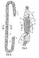
- One embodiment of the present inventionis a grommet (see FIG. 3 ).
- a preformed spiral cut thimbleoffers additional protection at the sling bite while still being removable (see FIGS. 16-18 ).
- FIG. 1is a front, elevational view of the preferred embodiment of the apparatus of the present invention
- FIG. 2is a front, elevational view of the preferred embodiment of the apparatus of the present invention showing the sling in a doubled configuration
- FIG. 3is a front, elevational view of a second embodiment of the apparatus of the present invention showing a grommet
- FIG. 4is a front, elevational view of a portion of the preferred embodiment of the apparatus of the present invention shown prior to formation in sling or grommet form;
- FIG. 5is a schematic, front, elevational view showing a portion of the apparatus of the present invention during forming
- FIG. 6is a front, elevational view of the preferred embodiment of the apparatus of the present invention showing a sling during forming
- FIG. 7is a front, elevation, fragmentary view of the preferred embodiment of the apparatus of the present invention.
- FIG. 8is a front view of the insert portion of the preferred embodiment of the apparatus of the present invention, an optional component;
- FIG. 9is a sectional view taken along lines 9 - 9 of FIG. 7 ;
- FIG. 10is a sectional view taken along lines 10 - 10 of FIG. 4 ;
- FIG. 11is a sectional view taken along lines 11 - 11 of FIG. 5 ;
- FIG. 12is a perspective, fragmentary view of the preferred embodiment of the apparatus of the present invention showing the spiral cut tube prior to cutting;
- FIG. 13is a fragmentary perspective view of the preferred embodiment of the apparatus of the present invention showing the spiral cut sleeve portion thereof;
- FIG. 14is a fragmentary perspective view of the preferred embodiment of the apparatus of the present invention illustrating the placement of the insert portion into the bite area;
- FIG. 15is a fragmentary perspective view of the preferred embodiment of the apparatus of the present invention showing two spiral cut sleeves in position at the bite area and at the splice area;
- FIG. 16is a fragmentary perspective view of the preferred embodiment of the apparatus of the present invention showing the preformed thimble with spiral cut end portions thereof;
- FIG. 17is a sectional view taken along lines 17 - 17 of FIG. 16 ;
- FIG. 18is a fragmentary, perspective view of the preferred embodiment of the apparatus of the present invention illustrating the preformed spiral cut thimble portion thereof;
- FIG. 19is a front, elevational, schematic view illustrating the beginning of construction of the grommet embodiment
- FIG. 20is a front elevation, schematic view illustrating a further construction of the grommet embodiment
- FIG. 21is yet another front, elevational, schematic view illustrating construction of the grommet embodiment
- FIG. 22is a front, elevation schematic view illustrating the grommet embodiment and illustrating placement of spiral cut sleeves at the bite and splice areas;
- FIGS. 23-25are front elevational views of the preferred embodiment of the apparatus of the present invention showing a sling during forming, and wherein a first spiral cut sleeve completely covers the lifting eye and a section of the sling next to the lifting eye, and a second spiral sleeve covers the first spiral sleeve on the sling next to the lifting eye.
- FIGS. 1 and 2show generally the preferred embodiment of the apparatus of the present invention designated generally by the numeral 10 .
- Lifting sling 10includes a sling member 11 (preferably polymeric, more preferably liquid crystal polymer) that can be provided with a pair of spaced apart lifting eyes 16 , 18 as shown in FIGS. 1 and 2 .
- sling member 11preferably polymeric, more preferably liquid crystal polymer
- the sling member 11is much longer and is doubled so that both of the lifting eyes 16 , 18 are positioned in side by side relationship and supported by hook 65 attached to crane lifting line 64 .
- FIG. 1a single strand configuration for sling 10 is shown with the lifting eye 16 being attached to hook 65 .
- the lower lifting eye 18is attached to shackle 21 which is affixed to both lifting eye 18 and load 20 to be lifted.
- Lifting eye 16provides an opening 17 that enables it to be attached to hook 65 of a crane and its lifting line 64 .
- eye 18has an opening 19 that enables it to be attached to an object to be lifted such as load 20 or to a shackle 21 that forms an interface between load 20 and eye 18 .
- the sling member 11is shown in FIG. 4 before assembly.
- a slingcan be constructed and used in the field of a selective length because the sling length can be changed at any time by the user. This is accomplished by beginning with a sling member 11 that is an elongated member comprised of a woven portion 27 having end portions 12 , 14 as shown in FIG. 4 .
- the end portion 12is preferably contained with band 13 to prevent unraveling.
- a band 15is provided at end portion 14 .
- the woven material 27 that comprises sling member 11is a liquid crystal polymer (LCP) fiber material that is very strong.
- LCPliquid crystal polymer
- Such a productis manufactured by Celanese Acetate LLC under the trademark Vectran®.
- liquid crystal polymer materialtypically has a tendency to abraid when used in the hostile environment of a lifting sling in an industrial plant.
- this materialcan carry a substantial load so long as the splice is loaded and maintained in tension, such as in a controlled setting (eg. lab).
- a controlled settingeg. lab
- slings of this typeare handled with little care. They can be, for example, thrown on the ground, rolled over by heavy vehicles, subjected to dragging across dirt, gravel, sand, etc. In such a hostile environment, the splice can easily shift positions or become completely disassembled.
- the present inventionprovides a plurality of spring cut or spiral cut sleeves such as sleeves 22 , 23 .
- These spiral cut sleeves 22 , 23include sleeves 22 that are configured to be positioned at the bite area 34 of a lifting eye 16 or 18 as shown in FIGS. 1-13 and 15 .
- the spiral cut sleeves 22 , 23are also provided at the area of splices, those sleeves being designated by the numeral 23 .
- the sling 10is provided with two spiral cut sleeves 22 at the bite area 34 of both lifting eyes 16 and 18 .
- the sling 10 in FIG. 1is provided with two spiral cut sleeves 23 that are provided at the splice area next to each of the lifting eyes 16 and 18 .
- the elongated sleeve 10is of the same configuration generally as the sling of FIG. 1 .
- spiral cut sleevesFor the grommet 70 of FIG. 3 , there are four spiral cut sleeves provided. These include the spiral cut sleeves 22 at the bite areas of the grommet 70 and the spiral cut sleeves 23 provided at the splice areas of the grommet 70 .
- FIGS. 5 , 6 and 7illustrate assembly of the lifting sling 10 of the present invention by a user in the field.
- the apparatus of the present inventionenables a user such as an engineer, crane operator, construction foreman or the like to construct a sling 10 of any desired length and to adjust the length of the sleeve in the field.
- a splicing tool 28is attached to end portion 14 of sling member 11 .
- a user's hands 24 , 25 in FIG. 5are moved together in the direction of arrows 26 , in order to thicken or expand a portion of the sling member 11 to produce the expanded section 30 shown in FIGS. 5 and 6 .
- the expanded section 30is also shown in a sectional view of FIG. 11 .
- FIG. 11should be compared with FIG. 10 , showing the normal cross sectional configuration of sling member 11 and specifically its woven portion 27 .
- the woven portion 27can be comprised of a plurality of for example, twelve (12) plies surrounding a central passageway 33 .
- the passageway 33has been greatly enlarged as shown to accommodate splicing tool 28 and end portion 14 of sling member 11 .
- Arrow 29 in FIG. 6schematically illustrates the placement of splicing tool 28 into opening 31 in expanded portion 30 of sling member 11 .
- the splicing tool 28is then routed a desired distance away from the opening 31 in the direction of arrow 29 .
- position arrow 32indicates schematically the terminal location for final placement of the end 14 portion of sling member 11 to complete the splice.
- this type of rope splice in generalis known, being referred to and illustrated for example in the New England Ropes Splicing Guide has a single braid eye splice.
- the problem encountered in the lifting artis that the use of such a single braid eye splice with very strong polymeric fibers such as liquid crystal polymer produces a sling that will easily slip or disassemble itself during field use and under hostile conditions found in industrial plants, construction sites, fabrication yards, etc. Therefore, there has not been a high strength, high tensile sling of liquid crystal polymer construction that could be field assembled, field adjusted, and still maintain integrity and strength during use.
- the splice that extends between opening 31 and position 32is covered with spiral cut sleeve 23 as shown in FIG. 7 .
- Arrow 66 in FIG. 7schematically illustrates the placement of spiral cut sleeve 23 upon the splice area that extends between opening 31 and position 32 .
- the usersimply continuously winds the spiral cut sleeve 23 upon the splice area as shown in FIG. 7 as indicated by the arrow 66 .
- each spiral cut sleeve 22 or 23is first construction of a tube 35 having a tube bore 36 and a tube wall 37 .
- Tube 35is preferably of a polyurethane material.
- the dotted line 38 in FIG. 12indicates the cut line for cutting tube 35 to produce spiral cut sleeves 22 or 23 .
- the tube 35can be any desired wall thickness for tube wall 37 and any desired bore diameter for bore 36 can be provided.
- a desired flexibilitycan be provided for spiral cut sleeve 22 or 23 .
- a desired compressioncan be obtained for applying compression at the splice area of any sling that is constructed according to the method and apparatus of the present invention.
- FIG. 9the compressive loading of the splice area is shown with the sleeve 23 tightly compacting the end portion 14 of sling member 11 within the central passageway 33 of a selected section of sling member 11 .
- a leading and trailing edge 39 , 40is defined as shown in FIG. 13 for the spiral cut sleeves 22 , 23 .
- These edges 39 , 40can be placed in a spaced apart orientation as shown in FIGS. 14 and 15 or can be placed very close together as shown with the spiral cut sleeves 23 in FIG. 1 .
- an insert 41is shown for thickening the sling 10 of the present invention or the grommet 70 of the present invention as selected by a user.
- the insert 41is shown more particularly in FIG. 8 as being comprised of a plurality of aligned fibers 42 , such as liquid crystal polymer fibers.
- the fibers 42are held together in an aligned group using a plurality of bands 43 for example. It has been found that the insert 41 provides an enhancement to the load capacity of sling 10 or grommet 11 when maintained in an unwoven configuration as shown in FIGS. 8 and 14 , the unwoven fibers 42 being simply placed side by side in an aligned configuration and held together with bands 43 .
- insert 41is shown being inserted into sling member 11 at lifting eye 18 , beginning at opening 45 and exiting at opening 46 .
- Arrows 44 in FIG. 14illustrate the path that is traveled by splicing tool 28 and the attached insert 41 .
- Arrow 47 in FIG. 14schematically illustrates the exit of splicing tool 28 from opening 46 .
- thimble 48includes a solid (eg. molded) portion 49 having a U shaped cross section as shown in FIG. 17 .
- the solid portion 49has a U shaped wall 52 that can be integrally connected to the spiral cut ends 50 , 51 such as by molding.
- the thimble 48includes solid portion 49 having a concavity 53 and a convex outer surface 54 .
- the concavity 53is occupied by a portion of the lifting eye 18 at the bite area 34 .
- the solid portion 49has edges 55 , 56 as shown in FIGS. 16 and 17 .
- a pair of spiral cut sleeve end portions 50 , 51are attached (eg. integrally molded) to solid portion 49 as shown in FIG. 16 .
- a spiral cut thimble sleeve 57is shown that is formed by molding, for example. This differs from the embodiment of FIGS. 12 and 13 for the sleeves 22 , 23 in that the spiral cut thimble 57 is formed in the shape shown in FIG. 18 , designed to track the shape of a lifting eye 16 or 18 .
- the spiral cut thimble 57is thus adapted to be placed at the bite area 34 of a lifting eye 16 or 18 or at the bite area of a grommet 70 .
- the spiral cut thimble 57has an outer wall 58 that is segmented, having leading and trailing edges 60 , 61 , a bore 59 , and ends 62 , 63 .
- FIGS. 23-25a variation is disclosed for the placement of the spiral cut sleeves 22 , 23 .
- the spiral cut sleeve 23is first being shown applied to a lifting eye 18 .
- FIGS. 22 and 23illustrate that the lifting eye 18 is completely covered with spiral cut sleeve 23 .
- a second spiral cut sleeve 23is applied over the first spiral cut sleeve 22 but only at a position directly above the lifting eye 18 as shown i FIG. 25 .
- grommet 70is shown beginning with an elongated grommet member 68 having end portions 69 , 71 .
- An entry point 72is selected for placement of splicing tool 73 thereinto.
- Arrow 74indicates schematically the insertion of splicing tool 73 into the central passageway of grommet member 68 .
- the cross sectional configuration of the grommet member 68can be identical to that of the sling member 11 shown in FIGS. 10 and 11 .
- the numeral 75indicates the position of end 71 after being embedded in the passageway of grommet member 68 .
- the splicing tool 73is attached to end 69 and inserted into opening 76 as indicated by arrow 77 in FIG. 21 .
- FIG. 22the end 69 of grommet member 68 is embedded to the position 78 shown in FIG. 22 .
- spiral cut sleeves 23are placed over each of the splice areas as shown in FIG. 22 .
- the areas to be attached to a lifting crane or a load to be liftedare covered with spiral cut sleeves 23 or either of the thimbles 48 , 57 shown in FIGS. 16-18 .
- the completed grommet 70is shown in FIG. 3 being attached to hook 65 attached to lifting lines 64 at one end. The other end of grommet 70 attaches at shackle 21 to load 20 .
Landscapes
- Engineering & Computer Science (AREA)
- Mechanical Engineering (AREA)
- Load-Engaging Elements For Cranes (AREA)
Abstract
Description
| Description | ||
| 10 | lifting sling | |
| 11 | ||
| 12 | ||
| 13 | ||
| 14 | ||
| 15 | ||
| 16 | lifting | |
| 17 | ||
| 18 | lifting | |
| 19 | ||
| 20 | ||
| 21 | ||
| 22 | spiral cut | |
| 23 | spiral cut | |
| 24 | user's | |
| 25 | user's | |
| 26 | ||
| 27 | woven | |
| 28 | ||
| 29 | ||
| 30 | expanded | |
| 31 | ||
| 32 | ||
| 33 | ||
| 34 | ||
| 35 | ||
| 36 | tube bore | |
| 37 | ||
| 38 | ||
| 39 | ||
| 40 | ||
| 41 | ||
| 42 | ||
| 43 | ||
| 44 | ||
| 45 | ||
| 46 | ||
| 47 | ||
| 48 | ||
| 49 | ||
| 50 | spiral cut | |
| 51 | spiral cut | |
| 52 | ||
| 53 | ||
| 54 | ||
| 55 | ||
| 56 | ||
| 57 | spiral cut | |
| 58 | ||
| 59 | bore | |
| 60 | ||
| 61 | ||
| 62 | ||
| 63 | ||
| 64 | lifting | |
| 65 | ||
| 66 | ||
| 67 | bite area | |
| 68 | ||
| 69 | ||
| 70 | ||
| 71 | ||
| 72 | ||
| 73 | splice tool | |
| 74 | ||
| 75 | ||
| 76 | ||
| 77 | ||
| 78 | position | |
Claims (56)
Priority Applications (1)
| Application Number | Priority Date | Filing Date | Title |
|---|---|---|---|
| US10/847,631US7399018B1 (en) | 2003-05-15 | 2004-05-17 | Lifting sling |
Applications Claiming Priority (2)
| Application Number | Priority Date | Filing Date | Title |
|---|---|---|---|
| US47069503P | 2003-05-15 | 2003-05-15 | |
| US10/847,631US7399018B1 (en) | 2003-05-15 | 2004-05-17 | Lifting sling |
Publications (1)
| Publication Number | Publication Date |
|---|---|
| US7399018B1true US7399018B1 (en) | 2008-07-15 |
Family
ID=39596620
Family Applications (1)
| Application Number | Title | Priority Date | Filing Date |
|---|---|---|---|
| US10/847,631Expired - LifetimeUS7399018B1 (en) | 2003-05-15 | 2004-05-17 | Lifting sling |
Country Status (1)
| Country | Link |
|---|---|
| US (1) | US7399018B1 (en) |
Cited By (81)
| Publication number | Priority date | Publication date | Assignee | Title |
|---|---|---|---|---|
| US20090301372A1 (en)* | 2006-03-29 | 2009-12-10 | Jon Khachaturian | Marine lifting apparatus |
| US20100229777A1 (en)* | 2007-12-17 | 2010-09-16 | Jon Khachaturian | Marine lifting apparatus |
| US7845296B1 (en) | 2006-12-13 | 2010-12-07 | Jon Khachaturian | Marine lifting apparatus |
| US7908988B1 (en) | 2007-11-14 | 2011-03-22 | Jon Khachaturian | Method and apparatus for salvaging underwater objects |
| US8251998B2 (en) | 2006-08-16 | 2012-08-28 | Biomet Sports Medicine, Llc | Chondral defect repair |
| US8273106B2 (en) | 2006-02-03 | 2012-09-25 | Biomet Sports Medicine, Llc | Soft tissue repair and conduit device |
| US8292921B2 (en) | 2006-02-03 | 2012-10-23 | Biomet Sports Medicine, Llc | Soft tissue repair device and associated methods |
| US20120267414A1 (en)* | 2011-04-22 | 2012-10-25 | Sewell Terry A | Methods and systems for removably coupling consumable parts within a system |
| US8298262B2 (en) | 2006-02-03 | 2012-10-30 | Biomet Sports Medicine, Llc | Method for tissue fixation |
| US8303604B2 (en) | 2004-11-05 | 2012-11-06 | Biomet Sports Medicine, Llc | Soft tissue repair device and method |
| US8337525B2 (en) | 2006-02-03 | 2012-12-25 | Biomet Sports Medicine, Llc | Soft tissue repair device and associated methods |
| US8343227B2 (en) | 2009-05-28 | 2013-01-01 | Biomet Manufacturing Corp. | Knee prosthesis assembly with ligament link |
| US8361113B2 (en) | 2006-02-03 | 2013-01-29 | Biomet Sports Medicine, Llc | Method and apparatus for coupling soft tissue to a bone |
| US8409253B2 (en) | 2006-02-03 | 2013-04-02 | Biomet Sports Medicine, Llc | Soft tissue repair assembly and associated method |
| US8448555B2 (en) | 2010-07-28 | 2013-05-28 | Triaxial Structures, Inc. | Braided loop utilizing bifurcation technology |
| WO2013079459A1 (en)* | 2011-11-28 | 2013-06-06 | Teufelberger Gesellschaft M.B.H. | Cord eye |
| US8460319B2 (en) | 2010-01-11 | 2013-06-11 | Anulex Technologies, Inc. | Intervertebral disc annulus repair system and method |
| US8500818B2 (en) | 2006-09-29 | 2013-08-06 | Biomet Manufacturing, Llc | Knee prosthesis assembly with ligament link |
| US8506597B2 (en) | 2011-10-25 | 2013-08-13 | Biomet Sports Medicine, Llc | Method and apparatus for interosseous membrane reconstruction |
| US8551140B2 (en) | 2004-11-05 | 2013-10-08 | Biomet Sports Medicine, Llc | Method and apparatus for coupling soft tissue to bone |
| US8562647B2 (en) | 2006-09-29 | 2013-10-22 | Biomet Sports Medicine, Llc | Method and apparatus for securing soft tissue to bone |
| US8562645B2 (en) | 2006-09-29 | 2013-10-22 | Biomet Sports Medicine, Llc | Method and apparatus for forming a self-locking adjustable loop |
| US8574235B2 (en) | 2006-02-03 | 2013-11-05 | Biomet Sports Medicine, Llc | Method for trochanteric reattachment |
| US8597327B2 (en) | 2006-02-03 | 2013-12-03 | Biomet Manufacturing, Llc | Method and apparatus for sternal closure |
| US8608777B2 (en) | 2006-02-03 | 2013-12-17 | Biomet Sports Medicine | Method and apparatus for coupling soft tissue to a bone |
| US8652171B2 (en) | 2006-02-03 | 2014-02-18 | Biomet Sports Medicine, Llc | Method and apparatus for soft tissue fixation |
| US8652172B2 (en) | 2006-02-03 | 2014-02-18 | Biomet Sports Medicine, Llc | Flexible anchors for tissue fixation |
| US8672968B2 (en) | 2006-09-29 | 2014-03-18 | Biomet Sports Medicine, Llc | Method for implanting soft tissue |
| US8672969B2 (en) | 2006-09-29 | 2014-03-18 | Biomet Sports Medicine, Llc | Fracture fixation device |
| US20140178615A1 (en)* | 2012-11-12 | 2014-06-26 | David Andrew Broadway | Ribbed woven material |
| US8771352B2 (en) | 2011-05-17 | 2014-07-08 | Biomet Sports Medicine, Llc | Method and apparatus for tibial fixation of an ACL graft |
| US8793843B2 (en) | 2010-08-13 | 2014-08-05 | Matthew Khachaturian | Lifting sling grommet connector and method |
| US8801783B2 (en) | 2006-09-29 | 2014-08-12 | Biomet Sports Medicine, Llc | Prosthetic ligament system for knee joint |
| US8840645B2 (en) | 2004-11-05 | 2014-09-23 | Biomet Sports Medicine, Llc | Method and apparatus for coupling soft tissue to a bone |
| WO2014152342A1 (en)* | 2013-03-15 | 2014-09-25 | Yale Cordage Inc. | Multi part synthetic eye and eye sling |
| US8932331B2 (en) | 2006-02-03 | 2015-01-13 | Biomet Sports Medicine, Llc | Method and apparatus for coupling soft tissue to bone |
| US8936621B2 (en) | 2006-02-03 | 2015-01-20 | Biomet Sports Medicine, Llc | Method and apparatus for forming a self-locking adjustable loop |
| US8968364B2 (en) | 2006-02-03 | 2015-03-03 | Biomet Sports Medicine, Llc | Method and apparatus for fixation of an ACL graft |
| US8985040B2 (en) | 2006-12-13 | 2015-03-24 | Jon Khachaturian | Marine lifting apparatus |
| US8998949B2 (en) | 2004-11-09 | 2015-04-07 | Biomet Sports Medicine, Llc | Soft tissue conduit device |
| US9017381B2 (en) | 2007-04-10 | 2015-04-28 | Biomet Sports Medicine, Llc | Adjustable knotless loops |
| WO2015103223A1 (en) | 2013-12-30 | 2015-07-09 | Manitowoc Crane Companies, Llc | Lightweight flexible tensioning system for construction equipment |
| US9078644B2 (en) | 2006-09-29 | 2015-07-14 | Biomet Sports Medicine, Llc | Fracture fixation device |
| US9149267B2 (en) | 2006-02-03 | 2015-10-06 | Biomet Sports Medicine, Llc | Method and apparatus for coupling soft tissue to a bone |
| USD743639S1 (en)* | 2014-07-31 | 2015-11-17 | C.B. Worldwide, Inc. | Center knotted braided rope pet toy |
| US20150337490A1 (en)* | 2014-05-15 | 2015-11-26 | Southern Weaving Company | Rope products, systems, methods and applications |
| US20160025941A1 (en)* | 2014-07-24 | 2016-01-28 | Verizon Patent And Licensing Inc. | Eccentric cut sleeve for optical fiber adapter |
| US9271713B2 (en) | 2006-02-03 | 2016-03-01 | Biomet Sports Medicine, Llc | Method and apparatus for tensioning a suture |
| US20160095421A1 (en)* | 2014-10-06 | 2016-04-07 | Ty-Flot, Inc. | Drop-prevention apparatus for a rolled product |
| US20160095420A1 (en)* | 2014-10-06 | 2016-04-07 | Ty-Flot, Inc. | Drop-prevention apparatus for a rolled product |
| US9314241B2 (en) | 2011-11-10 | 2016-04-19 | Biomet Sports Medicine, Llc | Apparatus for coupling soft tissue to a bone |
| US9357991B2 (en) | 2011-11-03 | 2016-06-07 | Biomet Sports Medicine, Llc | Method and apparatus for stitching tendons |
| US9370350B2 (en) | 2011-11-10 | 2016-06-21 | Biomet Sports Medicine, Llc | Apparatus for coupling soft tissue to a bone |
| US9381013B2 (en) | 2011-11-10 | 2016-07-05 | Biomet Sports Medicine, Llc | Method for coupling soft tissue to a bone |
| US9538998B2 (en) | 2006-02-03 | 2017-01-10 | Biomet Sports Medicine, Llc | Method and apparatus for fracture fixation |
| WO2017013107A1 (en) | 2015-07-22 | 2017-01-26 | Teufelberger Fiber Rope Gmbh | Rope made of textile fiber material |
| US9572655B2 (en) | 2004-11-05 | 2017-02-21 | Biomet Sports Medicine, Llc | Method and apparatus for coupling soft tissue to a bone |
| US9615822B2 (en) | 2014-05-30 | 2017-04-11 | Biomet Sports Medicine, Llc | Insertion tools and method for soft anchor |
| US9700291B2 (en) | 2014-06-03 | 2017-07-11 | Biomet Sports Medicine, Llc | Capsule retractor |
| US9737294B2 (en) | 2013-01-28 | 2017-08-22 | Cartiva, Inc. | Method and system for orthopedic repair |
| US9757119B2 (en) | 2013-03-08 | 2017-09-12 | Biomet Sports Medicine, Llc | Visual aid for identifying suture limbs arthroscopically |
| US9801708B2 (en) | 2004-11-05 | 2017-10-31 | Biomet Sports Medicine, Llc | Method and apparatus for coupling soft tissue to a bone |
| US9918827B2 (en)* | 2013-03-14 | 2018-03-20 | Biomet Sports Medicine, Llc | Scaffold for spring ligament repair |
| US9918826B2 (en)* | 2006-09-29 | 2018-03-20 | Biomet Sports Medicine, Llc | Scaffold for spring ligament repair |
| US9955980B2 (en) | 2015-02-24 | 2018-05-01 | Biomet Sports Medicine, Llc | Anatomic soft tissue repair |
| US10039543B2 (en) | 2014-08-22 | 2018-08-07 | Biomet Sports Medicine, Llc | Non-sliding soft anchor |
| US10136886B2 (en) | 2013-12-20 | 2018-11-27 | Biomet Sports Medicine, Llc | Knotless soft tissue devices and techniques |
| US10179012B2 (en) | 2013-01-28 | 2019-01-15 | Cartiva, Inc. | Systems and methods for orthopedic repair |
| US10517587B2 (en) | 2006-02-03 | 2019-12-31 | Biomet Sports Medicine, Llc | Method and apparatus for forming a self-locking adjustable loop |
| US10912551B2 (en) | 2015-03-31 | 2021-02-09 | Biomet Sports Medicine, Llc | Suture anchor with soft anchor of electrospun fibers |
| USD916420S1 (en)* | 2016-10-28 | 2021-04-13 | Bubba Rope, LLC | Winch line eye |
| US11259792B2 (en) | 2006-02-03 | 2022-03-01 | Biomet Sports Medicine, Llc | Method and apparatus for coupling anatomical features |
| US11259794B2 (en) | 2006-09-29 | 2022-03-01 | Biomet Sports Medicine, Llc | Method for implanting soft tissue |
| US11278758B2 (en)* | 2019-03-15 | 2022-03-22 | Hyper Wear, Inc. | Weighted triple-braided exercise rope |
| US11311287B2 (en) | 2006-02-03 | 2022-04-26 | Biomet Sports Medicine, Llc | Method for tissue fixation |
| US20220228316A1 (en)* | 2019-05-21 | 2022-07-21 | Lankhorst Touwfabrieken B.V. | Rope having an end connector segment comprising two rope-branches for making noosed connections |
| US12096928B2 (en) | 2009-05-29 | 2024-09-24 | Biomet Sports Medicine, Llc | Method and apparatus for coupling soft tissue to a bone |
| US12139850B2 (en)* | 2022-07-29 | 2024-11-12 | Samyoung Jung | Rope for trawl nets with high-strength eye-splice |
| US12245759B2 (en) | 2008-08-22 | 2025-03-11 | Biomet Sports Medicine, Llc | Method and apparatus for coupling soft tissue to bone |
| US12329373B2 (en) | 2011-05-02 | 2025-06-17 | Biomet Sports Medicine, Llc | Method and apparatus for soft tissue fixation |
| US12419632B2 (en) | 2008-08-22 | 2025-09-23 | Biomet Sports Medicine, Llc | Method and apparatus for coupling anatomical features |
Citations (9)
| Publication number | Priority date | Publication date | Assignee | Title |
|---|---|---|---|---|
| US2558553A (en)* | 1949-09-30 | 1951-06-26 | American Steel & Wire Co | Splice and method of making same |
| US2643638A (en)* | 1951-11-26 | 1953-06-30 | Joseph F Villmer | Swiveled hondoo |
| US2947504A (en)* | 1955-02-03 | 1960-08-02 | Preformed Line Products Co | Cable suspension and anchoring means and method |
| US2981053A (en)* | 1960-03-01 | 1961-04-25 | Harrison Steele | Steel wrap method for bowstring loops |
| US3007300A (en)* | 1946-09-20 | 1961-11-07 | Preformed Line Products Co | Helically-preformed wire envelope and methods of use |
| US3067570A (en)* | 1960-02-01 | 1962-12-11 | Impact Extrusions Inc | Rope sling and process for forming the sling |
| US3120734A (en)* | 1961-11-29 | 1964-02-11 | American Chain & Cable Co | Splices |
| US3338046A (en)* | 1965-12-29 | 1967-08-29 | Cable Covers Ltd | Looped wire rope or cable |
| US5699657A (en)* | 1996-05-23 | 1997-12-23 | Paulson; William Thomas | Braided line splices and methods of splicing to form same |
- 2004
- 2004-05-17USUS10/847,631patent/US7399018B1/ennot_activeExpired - Lifetime
Patent Citations (9)
| Publication number | Priority date | Publication date | Assignee | Title |
|---|---|---|---|---|
| US3007300A (en)* | 1946-09-20 | 1961-11-07 | Preformed Line Products Co | Helically-preformed wire envelope and methods of use |
| US2558553A (en)* | 1949-09-30 | 1951-06-26 | American Steel & Wire Co | Splice and method of making same |
| US2643638A (en)* | 1951-11-26 | 1953-06-30 | Joseph F Villmer | Swiveled hondoo |
| US2947504A (en)* | 1955-02-03 | 1960-08-02 | Preformed Line Products Co | Cable suspension and anchoring means and method |
| US3067570A (en)* | 1960-02-01 | 1962-12-11 | Impact Extrusions Inc | Rope sling and process for forming the sling |
| US2981053A (en)* | 1960-03-01 | 1961-04-25 | Harrison Steele | Steel wrap method for bowstring loops |
| US3120734A (en)* | 1961-11-29 | 1964-02-11 | American Chain & Cable Co | Splices |
| US3338046A (en)* | 1965-12-29 | 1967-08-29 | Cable Covers Ltd | Looped wire rope or cable |
| US5699657A (en)* | 1996-05-23 | 1997-12-23 | Paulson; William Thomas | Braided line splices and methods of splicing to form same |
Cited By (221)
| Publication number | Priority date | Publication date | Assignee | Title |
|---|---|---|---|---|
| US8303604B2 (en) | 2004-11-05 | 2012-11-06 | Biomet Sports Medicine, Llc | Soft tissue repair device and method |
| US9504460B2 (en) | 2004-11-05 | 2016-11-29 | Biomet Sports Medicine, LLC. | Soft tissue repair device and method |
| US9801708B2 (en) | 2004-11-05 | 2017-10-31 | Biomet Sports Medicine, Llc | Method and apparatus for coupling soft tissue to a bone |
| US9572655B2 (en) | 2004-11-05 | 2017-02-21 | Biomet Sports Medicine, Llc | Method and apparatus for coupling soft tissue to a bone |
| US8840645B2 (en) | 2004-11-05 | 2014-09-23 | Biomet Sports Medicine, Llc | Method and apparatus for coupling soft tissue to a bone |
| US10265064B2 (en) | 2004-11-05 | 2019-04-23 | Biomet Sports Medicine, Llc | Soft tissue repair device and method |
| US11109857B2 (en) | 2004-11-05 | 2021-09-07 | Biomet Sports Medicine, Llc | Soft tissue repair device and method |
| US8551140B2 (en) | 2004-11-05 | 2013-10-08 | Biomet Sports Medicine, Llc | Method and apparatus for coupling soft tissue to bone |
| US8998949B2 (en) | 2004-11-09 | 2015-04-07 | Biomet Sports Medicine, Llc | Soft tissue conduit device |
| US8968364B2 (en) | 2006-02-03 | 2015-03-03 | Biomet Sports Medicine, Llc | Method and apparatus for fixation of an ACL graft |
| US10098629B2 (en) | 2006-02-03 | 2018-10-16 | Biomet Sports Medicine, Llc | Method and apparatus for coupling soft tissue to a bone |
| US8292921B2 (en) | 2006-02-03 | 2012-10-23 | Biomet Sports Medicine, Llc | Soft tissue repair device and associated methods |
| US10702259B2 (en) | 2006-02-03 | 2020-07-07 | Biomet Sports Medicine, Llc | Soft tissue repair assembly and associated method |
| US8298262B2 (en) | 2006-02-03 | 2012-10-30 | Biomet Sports Medicine, Llc | Method for tissue fixation |
| US9561025B2 (en) | 2006-02-03 | 2017-02-07 | Biomet Sports Medicine, Llc | Soft tissue repair device and associated methods |
| US8337525B2 (en) | 2006-02-03 | 2012-12-25 | Biomet Sports Medicine, Llc | Soft tissue repair device and associated methods |
| US10695052B2 (en) | 2006-02-03 | 2020-06-30 | Biomet Sports Medicine, Llc | Method and apparatus for coupling soft tissue to a bone |
| US8361113B2 (en) | 2006-02-03 | 2013-01-29 | Biomet Sports Medicine, Llc | Method and apparatus for coupling soft tissue to a bone |
| US8409253B2 (en) | 2006-02-03 | 2013-04-02 | Biomet Sports Medicine, Llc | Soft tissue repair assembly and associated method |
| US10687803B2 (en) | 2006-02-03 | 2020-06-23 | Biomet Sports Medicine, Llc | Method and apparatus for coupling soft tissue to a bone |
| US10675073B2 (en) | 2006-02-03 | 2020-06-09 | Biomet Sports Medicine, Llc | Method and apparatus for sternal closure |
| US10603029B2 (en) | 2006-02-03 | 2020-03-31 | Biomet Sports Medicine, Llc | Method and apparatus for coupling soft tissue to bone |
| US10595851B2 (en) | 2006-02-03 | 2020-03-24 | Biomet Sports Medicine, Llc | Method and apparatus for coupling soft tissue to a bone |
| US11589859B2 (en) | 2006-02-03 | 2023-02-28 | Biomet Sports Medicine, Llc | Method and apparatus for coupling soft tissue to bone |
| US10716557B2 (en) | 2006-02-03 | 2020-07-21 | Biomet Sports Medicine, Llc | Method and apparatus for coupling anatomical features |
| US10542967B2 (en) | 2006-02-03 | 2020-01-28 | Biomet Sports Medicine, Llc | Method and apparatus for coupling soft tissue to a bone |
| US11259792B2 (en) | 2006-02-03 | 2022-03-01 | Biomet Sports Medicine, Llc | Method and apparatus for coupling anatomical features |
| US8574235B2 (en) | 2006-02-03 | 2013-11-05 | Biomet Sports Medicine, Llc | Method for trochanteric reattachment |
| US8597327B2 (en) | 2006-02-03 | 2013-12-03 | Biomet Manufacturing, Llc | Method and apparatus for sternal closure |
| US8608777B2 (en) | 2006-02-03 | 2013-12-17 | Biomet Sports Medicine | Method and apparatus for coupling soft tissue to a bone |
| US8632569B2 (en) | 2006-02-03 | 2014-01-21 | Biomet Sports Medicine, Llc | Soft tissue repair device and associated methods |
| US8652171B2 (en) | 2006-02-03 | 2014-02-18 | Biomet Sports Medicine, Llc | Method and apparatus for soft tissue fixation |
| US10441264B2 (en) | 2006-02-03 | 2019-10-15 | Biomet Sports Medicine, Llc | Soft tissue repair assembly and associated method |
| US8652172B2 (en) | 2006-02-03 | 2014-02-18 | Biomet Sports Medicine, Llc | Flexible anchors for tissue fixation |
| US10729430B2 (en) | 2006-02-03 | 2020-08-04 | Biomet Sports Medicine, Llc | Method and apparatus for coupling soft tissue to a bone |
| US10398428B2 (en) | 2006-02-03 | 2019-09-03 | Biomet Sports Medicine, Llc | Method and apparatus for coupling anatomical features |
| US8721684B2 (en) | 2006-02-03 | 2014-05-13 | Biomet Sports Medicine, Llc | Method and apparatus for coupling anatomical features |
| US10321906B2 (en) | 2006-02-03 | 2019-06-18 | Biomet Sports Medicine, Llc | Method for tissue fixation |
| US8771316B2 (en) | 2006-02-03 | 2014-07-08 | Biomet Sports Medicine, Llc | Method and apparatus for coupling anatomical features |
| US9603591B2 (en) | 2006-02-03 | 2017-03-28 | Biomet Sports Medicine, Llc | Flexible anchors for tissue fixation |
| US9538998B2 (en) | 2006-02-03 | 2017-01-10 | Biomet Sports Medicine, Llc | Method and apparatus for fracture fixation |
| US10251637B2 (en) | 2006-02-03 | 2019-04-09 | Biomet Sports Medicine, Llc | Soft tissue repair device and associated methods |
| US10932770B2 (en) | 2006-02-03 | 2021-03-02 | Biomet Sports Medicine, Llc | Soft tissue repair device and associated methods |
| US10729421B2 (en) | 2006-02-03 | 2020-08-04 | Biomet Sports Medicine, Llc | Method and apparatus for soft tissue fixation |
| US11116495B2 (en) | 2006-02-03 | 2021-09-14 | Biomet Sports Medicine, Llc | Soft tissue repair assembly and associated method |
| US10154837B2 (en) | 2006-02-03 | 2018-12-18 | Biomet Sports Medicine, Llc | Method and apparatus for coupling soft tissue to a bone |
| US8932331B2 (en) | 2006-02-03 | 2015-01-13 | Biomet Sports Medicine, Llc | Method and apparatus for coupling soft tissue to bone |
| US8936621B2 (en) | 2006-02-03 | 2015-01-20 | Biomet Sports Medicine, Llc | Method and apparatus for forming a self-locking adjustable loop |
| US11065103B2 (en) | 2006-02-03 | 2021-07-20 | Biomet Sports Medicine, Llc | Method and apparatus for fixation of an ACL graft |
| US10092288B2 (en) | 2006-02-03 | 2018-10-09 | Biomet Sports Medicine, Llc | Method and apparatus for coupling soft tissue to a bone |
| US11039826B2 (en) | 2006-02-03 | 2021-06-22 | Biomet Sports Medicine, Llc | Method and apparatus for forming a self-locking adjustable loop |
| US8273106B2 (en) | 2006-02-03 | 2012-09-25 | Biomet Sports Medicine, Llc | Soft tissue repair and conduit device |
| US9005287B2 (en) | 2006-02-03 | 2015-04-14 | Biomet Sports Medicine, Llc | Method for bone reattachment |
| US10517587B2 (en) | 2006-02-03 | 2019-12-31 | Biomet Sports Medicine, Llc | Method and apparatus for forming a self-locking adjustable loop |
| US10022118B2 (en) | 2006-02-03 | 2018-07-17 | Biomet Sports Medicine, Llc | Method and apparatus for coupling soft tissue to a bone |
| US9532777B2 (en) | 2006-02-03 | 2017-01-03 | Biomet Sports Medicine, Llc | Method and apparatus for coupling soft tissue to a bone |
| US10004489B2 (en) | 2006-02-03 | 2018-06-26 | Biomet Sports Medicine, Llc | Method and apparatus for coupling soft tissue to a bone |
| US9149267B2 (en) | 2006-02-03 | 2015-10-06 | Biomet Sports Medicine, Llc | Method and apparatus for coupling soft tissue to a bone |
| US9173651B2 (en) | 2006-02-03 | 2015-11-03 | Biomet Sports Medicine, Llc | Soft tissue repair device and associated methods |
| US10004588B2 (en) | 2006-02-03 | 2018-06-26 | Biomet Sports Medicine, Llc | Method and apparatus for fixation of an ACL graft |
| US12096931B2 (en) | 2006-02-03 | 2024-09-24 | Biomet Sports Medicine, Llc | Method and apparatus for coupling soft tissue to a bone |
| US9993241B2 (en) | 2006-02-03 | 2018-06-12 | Biomet Sports Medicine, Llc | Method and apparatus for forming a self-locking adjustable loop |
| US11284884B2 (en) | 2006-02-03 | 2022-03-29 | Biomet Sports Medicine, Llc | Method and apparatus for coupling soft tissue to a bone |
| US12064101B2 (en) | 2006-02-03 | 2024-08-20 | Biomet Sports Medicine, Llc | Method and apparatus for forming a self-locking adjustable loop |
| US11998185B2 (en) | 2006-02-03 | 2024-06-04 | Biomet Sports Medicine, Llc | Method and apparatus for coupling soft tissue to a bone |
| US11896210B2 (en) | 2006-02-03 | 2024-02-13 | Biomet Sports Medicine, Llc | Method and apparatus for coupling soft tissue to a bone |
| US11311287B2 (en) | 2006-02-03 | 2022-04-26 | Biomet Sports Medicine, Llc | Method for tissue fixation |
| US9271713B2 (en) | 2006-02-03 | 2016-03-01 | Biomet Sports Medicine, Llc | Method and apparatus for tensioning a suture |
| US11819205B2 (en) | 2006-02-03 | 2023-11-21 | Biomet Sports Medicine, Llc | Soft tissue repair device and associated methods |
| US11786236B2 (en) | 2006-02-03 | 2023-10-17 | Biomet Sports Medicine, Llc | Method and apparatus for coupling anatomical features |
| US11730464B2 (en) | 2006-02-03 | 2023-08-22 | Biomet Sports Medicine, Llc | Soft tissue repair assembly and associated method |
| US11317907B2 (en) | 2006-02-03 | 2022-05-03 | Biomet Sports Medicine, Llc | Method and apparatus for forming a self-locking adjustable loop |
| US11723648B2 (en) | 2006-02-03 | 2023-08-15 | Biomet Sports Medicine, Llc | Method and apparatus for soft tissue fixation |
| US10987099B2 (en) | 2006-02-03 | 2021-04-27 | Biomet Sports Medicine, Llc | Method for tissue fixation |
| US9801620B2 (en) | 2006-02-03 | 2017-10-31 | Biomet Sports Medicine, Llc | Method and apparatus for coupling soft tissue to bone |
| US9763656B2 (en) | 2006-02-03 | 2017-09-19 | Biomet Sports Medicine, Llc | Method and apparatus for soft tissue fixation |
| US9510819B2 (en) | 2006-02-03 | 2016-12-06 | Biomet Sports Medicine, Llc | Soft tissue repair device and associated methods |
| US9402621B2 (en) | 2006-02-03 | 2016-08-02 | Biomet Sports Medicine, LLC. | Method for tissue fixation |
| US11446019B2 (en) | 2006-02-03 | 2022-09-20 | Biomet Sports Medicine, Llc | Method and apparatus for coupling soft tissue to a bone |
| US9414833B2 (en) | 2006-02-03 | 2016-08-16 | Biomet Sports Medicine, Llc | Soft tissue repair assembly and associated method |
| US11471147B2 (en) | 2006-02-03 | 2022-10-18 | Biomet Sports Medicine, Llc | Method and apparatus for coupling soft tissue to a bone |
| US9642661B2 (en) | 2006-02-03 | 2017-05-09 | Biomet Sports Medicine, Llc | Method and Apparatus for Sternal Closure |
| US11617572B2 (en) | 2006-02-03 | 2023-04-04 | Biomet Sports Medicine, Llc | Soft tissue repair device and associated methods |
| US9468433B2 (en) | 2006-02-03 | 2016-10-18 | Biomet Sports Medicine, Llc | Method and apparatus for forming a self-locking adjustable loop |
| US9622736B2 (en) | 2006-02-03 | 2017-04-18 | Biomet Sports Medicine, Llc | Soft tissue repair device and associated methods |
| US9510821B2 (en) | 2006-02-03 | 2016-12-06 | Biomet Sports Medicine, Llc | Method and apparatus for coupling anatomical features |
| US9492158B2 (en) | 2006-02-03 | 2016-11-15 | Biomet Sports Medicine, Llc | Method and apparatus for coupling soft tissue to a bone |
| US9498204B2 (en) | 2006-02-03 | 2016-11-22 | Biomet Sports Medicine, Llc | Method and apparatus for coupling anatomical features |
| US10973507B2 (en) | 2006-02-03 | 2021-04-13 | Biomet Sports Medicine, Llc | Method and apparatus for coupling soft tissue to a bone |
| US9604710B2 (en) | 2006-03-29 | 2017-03-28 | Jon Khachaturian | Marine lifting apparatus |
| US11345452B2 (en) | 2006-03-29 | 2022-05-31 | Versabar, Inc. | Marine lifting apparatus |
| US20090301372A1 (en)* | 2006-03-29 | 2009-12-10 | Jon Khachaturian | Marine lifting apparatus |
| US8061289B2 (en) | 2006-03-29 | 2011-11-22 | Jon Khachaturian | Marine lifting apparatus |
| US10543890B2 (en) | 2006-03-29 | 2020-01-28 | Versabar, Inc. | Marine lifting apparatus |
| US8777956B2 (en) | 2006-08-16 | 2014-07-15 | Biomet Sports Medicine, Llc | Chondral defect repair |
| US8251998B2 (en) | 2006-08-16 | 2012-08-28 | Biomet Sports Medicine, Llc | Chondral defect repair |
| US8801783B2 (en) | 2006-09-29 | 2014-08-12 | Biomet Sports Medicine, Llc | Prosthetic ligament system for knee joint |
| US10517714B2 (en) | 2006-09-29 | 2019-12-31 | Biomet Sports Medicine, Llc | Ligament system for knee joint |
| US9486211B2 (en) | 2006-09-29 | 2016-11-08 | Biomet Sports Medicine, Llc | Method for implanting soft tissue |
| US10835232B2 (en) | 2006-09-29 | 2020-11-17 | Biomet Sports Medicine, Llc | Fracture fixation device |
| US9078644B2 (en) | 2006-09-29 | 2015-07-14 | Biomet Sports Medicine, Llc | Fracture fixation device |
| US10398430B2 (en) | 2006-09-29 | 2019-09-03 | Biomet Sports Medicine, Llc | Method for implanting soft tissue |
| US10349931B2 (en) | 2006-09-29 | 2019-07-16 | Biomet Sports Medicine, Llc | Fracture fixation device |
| US9681940B2 (en) | 2006-09-29 | 2017-06-20 | Biomet Sports Medicine, Llc | Ligament system for knee joint |
| US11672527B2 (en) | 2006-09-29 | 2023-06-13 | Biomet Sports Medicine, Llc | Method for implanting soft tissue |
| US9414925B2 (en) | 2006-09-29 | 2016-08-16 | Biomet Manufacturing, Llc | Method of implanting a knee prosthesis assembly with a ligament link |
| US9724090B2 (en) | 2006-09-29 | 2017-08-08 | Biomet Manufacturing, Llc | Method and apparatus for attaching soft tissue to bone |
| US11376115B2 (en) | 2006-09-29 | 2022-07-05 | Biomet Sports Medicine, Llc | Prosthetic ligament system for knee joint |
| US10695045B2 (en) | 2006-09-29 | 2020-06-30 | Biomet Sports Medicine, Llc | Method and apparatus for attaching soft tissue to bone |
| US8672968B2 (en) | 2006-09-29 | 2014-03-18 | Biomet Sports Medicine, Llc | Method for implanting soft tissue |
| US9788876B2 (en) | 2006-09-29 | 2017-10-17 | Biomet Sports Medicine, Llc | Fracture fixation device |
| US8672969B2 (en) | 2006-09-29 | 2014-03-18 | Biomet Sports Medicine, Llc | Fracture fixation device |
| US10743925B2 (en) | 2006-09-29 | 2020-08-18 | Biomet Sports Medicine, Llc | Fracture fixation device |
| US8562645B2 (en) | 2006-09-29 | 2013-10-22 | Biomet Sports Medicine, Llc | Method and apparatus for forming a self-locking adjustable loop |
| US8562647B2 (en) | 2006-09-29 | 2013-10-22 | Biomet Sports Medicine, Llc | Method and apparatus for securing soft tissue to bone |
| US9833230B2 (en) | 2006-09-29 | 2017-12-05 | Biomet Sports Medicine, Llc | Fracture fixation device |
| US8500818B2 (en) | 2006-09-29 | 2013-08-06 | Biomet Manufacturing, Llc | Knee prosthesis assembly with ligament link |
| US10610217B2 (en) | 2006-09-29 | 2020-04-07 | Biomet Sports Medicine, Llc | Method and apparatus for forming a self-locking adjustable loop |
| US11096684B2 (en) | 2006-09-29 | 2021-08-24 | Biomet Sports Medicine, Llc | Method and apparatus for forming a self-locking adjustable loop |
| US9918826B2 (en)* | 2006-09-29 | 2018-03-20 | Biomet Sports Medicine, Llc | Scaffold for spring ligament repair |
| US11259794B2 (en) | 2006-09-29 | 2022-03-01 | Biomet Sports Medicine, Llc | Method for implanting soft tissue |
| US9539003B2 (en) | 2006-09-29 | 2017-01-10 | Biomet Sports Medicine, LLC. | Method and apparatus for forming a self-locking adjustable loop |
| US10004493B2 (en) | 2006-09-29 | 2018-06-26 | Biomet Sports Medicine, Llc | Method for implanting soft tissue |
| US8985040B2 (en) | 2006-12-13 | 2015-03-24 | Jon Khachaturian | Marine lifting apparatus |
| US7845296B1 (en) | 2006-12-13 | 2010-12-07 | Jon Khachaturian | Marine lifting apparatus |
| US11612391B2 (en) | 2007-01-16 | 2023-03-28 | Biomet Sports Medicine, Llc | Soft tissue repair device and associated methods |
| US9017381B2 (en) | 2007-04-10 | 2015-04-28 | Biomet Sports Medicine, Llc | Adjustable knotless loops |
| US9861351B2 (en) | 2007-04-10 | 2018-01-09 | Biomet Sports Medicine, Llc | Adjustable knotless loops |
| US10729423B2 (en) | 2007-04-10 | 2020-08-04 | Biomet Sports Medicine, Llc | Adjustable knotless loops |
| US12303122B2 (en) | 2007-04-10 | 2025-05-20 | Biomet Sports Medicine, Llc | Adjustable knotless loops |
| US11185320B2 (en) | 2007-04-10 | 2021-11-30 | Biomet Sports Medicine, Llc | Adjustable knotless loops |
| US8240265B1 (en) | 2007-11-14 | 2012-08-14 | Jon Khachaturian | Method and apparatus for salvaging underwater objects |
| US7908988B1 (en) | 2007-11-14 | 2011-03-22 | Jon Khachaturian | Method and apparatus for salvaging underwater objects |
| US8240264B2 (en) | 2007-12-17 | 2012-08-14 | Jon Khachaturian | Marine lifting apparatus |
| US20110197799A1 (en)* | 2007-12-17 | 2011-08-18 | Jon Khachaturian | Marine lifting apparatus |
| US7886676B2 (en) | 2007-12-17 | 2011-02-15 | Jon Khachaturian | Marine lifting apparatus |
| US20100229777A1 (en)* | 2007-12-17 | 2010-09-16 | Jon Khachaturian | Marine lifting apparatus |
| US12419632B2 (en) | 2008-08-22 | 2025-09-23 | Biomet Sports Medicine, Llc | Method and apparatus for coupling anatomical features |
| US12245759B2 (en) | 2008-08-22 | 2025-03-11 | Biomet Sports Medicine, Llc | Method and apparatus for coupling soft tissue to bone |
| US11534159B2 (en) | 2008-08-22 | 2022-12-27 | Biomet Sports Medicine, Llc | Method and apparatus for coupling soft tissue to a bone |
| US10149767B2 (en) | 2009-05-28 | 2018-12-11 | Biomet Manufacturing, Llc | Method of implanting knee prosthesis assembly with ligament link |
| US8343227B2 (en) | 2009-05-28 | 2013-01-01 | Biomet Manufacturing Corp. | Knee prosthesis assembly with ligament link |
| US8900314B2 (en) | 2009-05-28 | 2014-12-02 | Biomet Manufacturing, Llc | Method of implanting a prosthetic knee joint assembly |
| US12096928B2 (en) | 2009-05-29 | 2024-09-24 | Biomet Sports Medicine, Llc | Method and apparatus for coupling soft tissue to a bone |
| US12251093B2 (en) | 2009-05-29 | 2025-03-18 | Biomet Sports Medicine, Llc | Method and apparatus for coupling soft tissue to a bone |
| US8460319B2 (en) | 2010-01-11 | 2013-06-11 | Anulex Technologies, Inc. | Intervertebral disc annulus repair system and method |
| US9795372B2 (en) | 2010-01-11 | 2017-10-24 | Krt Investors, Inc. | Intervertebral disc annulus repair system and bone anchor delivery tool |
| US8652153B2 (en) | 2010-01-11 | 2014-02-18 | Anulex Technologies, Inc. | Intervertebral disc annulus repair system and bone anchor delivery tool |
| US8448555B2 (en) | 2010-07-28 | 2013-05-28 | Triaxial Structures, Inc. | Braided loop utilizing bifurcation technology |
| US8793843B2 (en) | 2010-08-13 | 2014-08-05 | Matthew Khachaturian | Lifting sling grommet connector and method |
| US9249340B2 (en)* | 2011-04-22 | 2016-02-02 | The Boeing Company | Methods and systems for removably coupling consumable parts within a system |
| US20120267414A1 (en)* | 2011-04-22 | 2012-10-25 | Sewell Terry A | Methods and systems for removably coupling consumable parts within a system |
| US12329373B2 (en) | 2011-05-02 | 2025-06-17 | Biomet Sports Medicine, Llc | Method and apparatus for soft tissue fixation |
| US12336701B2 (en) | 2011-05-02 | 2025-06-24 | Biomet Sports Medicine, Llc | Method and apparatus for soft tissue fixation |
| US9216078B2 (en) | 2011-05-17 | 2015-12-22 | Biomet Sports Medicine, Llc | Method and apparatus for tibial fixation of an ACL graft |
| US8771352B2 (en) | 2011-05-17 | 2014-07-08 | Biomet Sports Medicine, Llc | Method and apparatus for tibial fixation of an ACL graft |
| US8506597B2 (en) | 2011-10-25 | 2013-08-13 | Biomet Sports Medicine, Llc | Method and apparatus for interosseous membrane reconstruction |
| US9445827B2 (en) | 2011-10-25 | 2016-09-20 | Biomet Sports Medicine, Llc | Method and apparatus for intraosseous membrane reconstruction |
| US10265159B2 (en) | 2011-11-03 | 2019-04-23 | Biomet Sports Medicine, Llc | Method and apparatus for stitching tendons |
| US9357991B2 (en) | 2011-11-03 | 2016-06-07 | Biomet Sports Medicine, Llc | Method and apparatus for stitching tendons |
| US11241305B2 (en) | 2011-11-03 | 2022-02-08 | Biomet Sports Medicine, Llc | Method and apparatus for stitching tendons |
| US10368856B2 (en) | 2011-11-10 | 2019-08-06 | Biomet Sports Medicine, Llc | Apparatus for coupling soft tissue to a bone |
| US9314241B2 (en) | 2011-11-10 | 2016-04-19 | Biomet Sports Medicine, Llc | Apparatus for coupling soft tissue to a bone |
| US9357992B2 (en) | 2011-11-10 | 2016-06-07 | Biomet Sports Medicine, Llc | Method for coupling soft tissue to a bone |
| US10363028B2 (en) | 2011-11-10 | 2019-07-30 | Biomet Sports Medicine, Llc | Method for coupling soft tissue to a bone |
| US9370350B2 (en) | 2011-11-10 | 2016-06-21 | Biomet Sports Medicine, Llc | Apparatus for coupling soft tissue to a bone |
| US9381013B2 (en) | 2011-11-10 | 2016-07-05 | Biomet Sports Medicine, Llc | Method for coupling soft tissue to a bone |
| US11534157B2 (en) | 2011-11-10 | 2022-12-27 | Biomet Sports Medicine, Llc | Method for coupling soft tissue to a bone |
| US9145639B2 (en) | 2011-11-28 | 2015-09-29 | Teufelberger Gesellschaft M.B.H. | Cord eye |
| WO2013079459A1 (en)* | 2011-11-28 | 2013-06-06 | Teufelberger Gesellschaft M.B.H. | Cord eye |
| US20160010277A1 (en)* | 2011-11-28 | 2016-01-14 | Teufelberger Gesellschaft M.B.H. | Cord eye |
| US10132033B2 (en)* | 2011-11-28 | 2018-11-20 | Teufelberger Gesellschaft M.B.H. | Cord eye |
| US20140178615A1 (en)* | 2012-11-12 | 2014-06-26 | David Andrew Broadway | Ribbed woven material |
| US10179012B2 (en) | 2013-01-28 | 2019-01-15 | Cartiva, Inc. | Systems and methods for orthopedic repair |
| US9737294B2 (en) | 2013-01-28 | 2017-08-22 | Cartiva, Inc. | Method and system for orthopedic repair |
| US11471199B2 (en) | 2013-01-28 | 2022-10-18 | Cartiva, Inc. | Systems and methods for orthopedic repair |
| US9757119B2 (en) | 2013-03-08 | 2017-09-12 | Biomet Sports Medicine, Llc | Visual aid for identifying suture limbs arthroscopically |
| US9918827B2 (en)* | 2013-03-14 | 2018-03-20 | Biomet Sports Medicine, Llc | Scaffold for spring ligament repair |
| US10758221B2 (en) | 2013-03-14 | 2020-09-01 | Biomet Sports Medicine, Llc | Scaffold for spring ligament repair |
| WO2014152342A1 (en)* | 2013-03-15 | 2014-09-25 | Yale Cordage Inc. | Multi part synthetic eye and eye sling |
| US9296593B2 (en)* | 2013-03-15 | 2016-03-29 | Yale Cordage Inc. | Multi part synthetic eye and eye sling |
| US9145280B2 (en) | 2013-03-15 | 2015-09-29 | Yale Cordage Inc. | Multi part synthetic eye and eye sling |
| CN105209368B (en)* | 2013-03-15 | 2017-07-07 | 耶鲁绳索有限公司 | Multi-part synthesizes eye and eye hoist cable |
| CN105209368A (en)* | 2013-03-15 | 2015-12-30 | 耶鲁绳索有限公司 | Multi part synthetic eye and eye sling |
| JP2016516140A (en)* | 2013-03-15 | 2016-06-02 | イェール・コーデージ・インコーポレーテッドYale Cordage Incorporated | Multi-part synthetic fiber type second hanging string |
| US10136886B2 (en) | 2013-12-20 | 2018-11-27 | Biomet Sports Medicine, Llc | Knotless soft tissue devices and techniques |
| US11648004B2 (en) | 2013-12-20 | 2023-05-16 | Biomet Sports Medicine, Llc | Knotless soft tissue devices and techniques |
| US12251100B2 (en) | 2013-12-20 | 2025-03-18 | Biomet Sports Medicine, Llc | Knotless soft tissue devices and techniques |
| US10806443B2 (en) | 2013-12-20 | 2020-10-20 | Biomet Sports Medicine, Llc | Knotless soft tissue devices and techniques |
| US10414638B2 (en)* | 2013-12-30 | 2019-09-17 | Manitowoc Crane Companies, Llc | Lightweight flexible tensioning system for construction equipment |
| CN105143087A (en)* | 2013-12-30 | 2015-12-09 | 马尼托瓦克起重机有限责任公司 | Lightweight flexible tensioning system for construction equipment |
| CN105143087B (en)* | 2013-12-30 | 2017-11-14 | 马尼托瓦克起重机有限责任公司 | Lightweight flexible tensioning system for construction equipment |
| CN107720573A (en)* | 2013-12-30 | 2018-02-23 | 马尼托瓦克起重机有限责任公司 | Lightweight flexible clamping system for Architectural Equipment |
| WO2015103223A1 (en) | 2013-12-30 | 2015-07-09 | Manitowoc Crane Companies, Llc | Lightweight flexible tensioning system for construction equipment |
| CN111807240B (en)* | 2013-12-30 | 2023-02-21 | 马尼托瓦克起重机有限责任公司 | Lightweight flexible tensioning system for construction equipment |
| CN107720573B (en)* | 2013-12-30 | 2020-07-28 | 马尼托瓦克起重机有限责任公司 | Lightweight flexible tensioning system for construction equipment |
| CN111807240A (en)* | 2013-12-30 | 2020-10-23 | 马尼托瓦克起重机有限责任公司 | Lightweight flexible tensioning system for construction equipment |
| JP2016525494A (en)* | 2013-12-30 | 2016-08-25 | マニタウォック クレイン カンパニーズ, エルエルシーManitowoc Crane Companies, Llc | Light and flexible tensioning system for construction machinery |
| US11649145B2 (en) | 2013-12-30 | 2023-05-16 | Manitowoc Crane Companies, Llc | Lightweight flexible tensioning system for construction equipment |
| US20150337490A1 (en)* | 2014-05-15 | 2015-11-26 | Southern Weaving Company | Rope products, systems, methods and applications |
| US9615822B2 (en) | 2014-05-30 | 2017-04-11 | Biomet Sports Medicine, Llc | Insertion tools and method for soft anchor |
| US9700291B2 (en) | 2014-06-03 | 2017-07-11 | Biomet Sports Medicine, Llc | Capsule retractor |
| US20160025941A1 (en)* | 2014-07-24 | 2016-01-28 | Verizon Patent And Licensing Inc. | Eccentric cut sleeve for optical fiber adapter |
| US9453974B2 (en)* | 2014-07-24 | 2016-09-27 | Verizon Patent And Licensing Inc. | Eccentric cut sleeve for optical fiber adapter |
| USD743639S1 (en)* | 2014-07-31 | 2015-11-17 | C.B. Worldwide, Inc. | Center knotted braided rope pet toy |
| US12193656B2 (en) | 2014-08-22 | 2025-01-14 | Biomet Sports Medicine, Llc | Non-sliding soft anchor |
| US10743856B2 (en) | 2014-08-22 | 2020-08-18 | Biomet Sports Medicine, Llc | Non-sliding soft anchor |
| US11219443B2 (en) | 2014-08-22 | 2022-01-11 | Biomet Sports Medicine, Llc | Non-sliding soft anchor |
| US10039543B2 (en) | 2014-08-22 | 2018-08-07 | Biomet Sports Medicine, Llc | Non-sliding soft anchor |
| US9480327B2 (en)* | 2014-10-06 | 2016-11-01 | Ty-Flot, Inc. | Drop-prevention apparatus for a rolled product |
| US20160095420A1 (en)* | 2014-10-06 | 2016-04-07 | Ty-Flot, Inc. | Drop-prevention apparatus for a rolled product |
| US20160095421A1 (en)* | 2014-10-06 | 2016-04-07 | Ty-Flot, Inc. | Drop-prevention apparatus for a rolled product |
| US9635925B2 (en)* | 2014-10-06 | 2017-05-02 | Ty-Flot, Inc. | Drop-prevention apparatus for a rolled product |
| US9955980B2 (en) | 2015-02-24 | 2018-05-01 | Biomet Sports Medicine, Llc | Anatomic soft tissue repair |
| US10912551B2 (en) | 2015-03-31 | 2021-02-09 | Biomet Sports Medicine, Llc | Suture anchor with soft anchor of electrospun fibers |
| WO2017013107A1 (en) | 2015-07-22 | 2017-01-26 | Teufelberger Fiber Rope Gmbh | Rope made of textile fiber material |
| USD916420S1 (en)* | 2016-10-28 | 2021-04-13 | Bubba Rope, LLC | Winch line eye |
| US11278758B2 (en)* | 2019-03-15 | 2022-03-22 | Hyper Wear, Inc. | Weighted triple-braided exercise rope |
| US20220228316A1 (en)* | 2019-05-21 | 2022-07-21 | Lankhorst Touwfabrieken B.V. | Rope having an end connector segment comprising two rope-branches for making noosed connections |
| US11965288B2 (en)* | 2019-05-21 | 2024-04-23 | Lankhorst Touwfabrieken B. V. | Rope having an end connector segment comprising two rope-branches for making noosed connections |
| US12139850B2 (en)* | 2022-07-29 | 2024-11-12 | Samyoung Jung | Rope for trawl nets with high-strength eye-splice |
Similar Documents
| Publication | Publication Date | Title |
|---|---|---|
| US7399018B1 (en) | Lifting sling | |
| CA1060065A (en) | Self-cinching cargo sling | |
| AU2017201487B2 (en) | Method of terminating a stranded synthetic filament cable | |
| US6331024B1 (en) | Lifting sling system with spaced, bi-directional loops | |
| US8727406B2 (en) | Round sling for lifting loads | |
| US9003757B2 (en) | Rope systems and methods for use as a round sling | |
| US3932697A (en) | Rope terminations and methods and apparatus for fabricating the same | |
| JP6606540B2 (en) | Mounting device | |
| US12371851B2 (en) | Coupling device | |
| US10640920B2 (en) | Winch line | |
| KR20120101538A (en) | Rope having a spliced eye, corresponding method of forming an eye and use of the rope | |
| US5561973A (en) | Flexible sling construction reinforced by eye parts extended in opposite longitudinal direction throughout multiple body parts in reverse rotational interwine | |
| US3722942A (en) | Load bearing strap | |
| US4255836A (en) | Continuous filament apex fittings and methods of manufacture thereof | |
| JP6054241B2 (en) | Pendant cord | |
| JP6093644B2 (en) | Pendant cord | |
| JP6093643B2 (en) | End structures of pendant cords and stretched carbon fiber strands | |
| AU2021236536B1 (en) | A safety assembly securing a tipping tray in a raised position | |
| US6353982B1 (en) | Net repair bridge | |
| US20180118532A1 (en) | Winch line attachment device and method for attaching winch line to winch | |
| WO2020070342A1 (en) | Hybrid shackle system | |
| WO2000017085A1 (en) | Lifting sling system having multiple strap components | |
| RU2796553C1 (en) | Ribbon rope for external suspension of aircraft and method for its manufacture | |
| US12359706B2 (en) | Shackle | |
| US2651824A (en) | Rope and cable joint |
Legal Events
| Date | Code | Title | Description |
|---|---|---|---|
| STCF | Information on status: patent grant | Free format text:PATENTED CASE | |
| FPAY | Fee payment | Year of fee payment:4 | |
| FPAY | Fee payment | Year of fee payment:8 | |
| AS | Assignment | Owner name:WELLS FARGO BANK, NATIONAL ASSOCIATION, NORTH CARO Free format text:SECURITY INTEREST;ASSIGNOR:VERSABAR, INC.;REEL/FRAME:042945/0055 Effective date:20170615 | |
| AS | Assignment | Owner name:VERSABAR, INC., TEXAS Free format text:ASSIGNMENT OF ASSIGNORS INTEREST;ASSIGNOR:KHACHATURIAN, JON E.;REEL/FRAME:043572/0098 Effective date:20170615 | |
| MAFP | Maintenance fee payment | Free format text:PAYMENT OF MAINTENANCE FEE, 12TH YR, SMALL ENTITY (ORIGINAL EVENT CODE: M2553); ENTITY STATUS OF PATENT OWNER: SMALL ENTITY Year of fee payment:12 | |
| AS | Assignment | Owner name:MC51, LLC, TEXAS Free format text:ASSIGNMENT OF SECURITY INTEREST;ASSIGNOR:WELLS FARGO BANK, NATIONAL ASSOCIATION;REEL/FRAME:067077/0781 Effective date:20210311 | |
| AS | Assignment | Owner name:VERSABAR, INC., TEXAS Free format text:RELEASE BY SECURED PARTY;ASSIGNOR:MC51, LLC;REEL/FRAME:067381/0630 Effective date:20240418 | |
| AS | Assignment | Owner name:GATORFUR, LLC, TEXAS Free format text:ASSIGNMENT OF ASSIGNORS INTEREST;ASSIGNOR:VERSABAR, INC.;REEL/FRAME:067571/0487 Effective date:20240419 |