US7398054B2 - Spatially selective UHF near field microstrip coupler device and RFID systems using device - Google Patents
Spatially selective UHF near field microstrip coupler device and RFID systems using deviceDownload PDFInfo
- Publication number
- US7398054B2 US7398054B2US10/604,996US60499603AUS7398054B2US 7398054 B2US7398054 B2US 7398054B2US 60499603 AUS60499603 AUS 60499603AUS 7398054 B2US7398054 B2US 7398054B2
- Authority
- US
- United States
- Prior art keywords
- lines
- transponder
- near field
- coupler
- coupling device
- Prior art date
- Legal status (The legal status is an assumption and is not a legal conclusion. Google has not performed a legal analysis and makes no representation as to the accuracy of the status listed.)
- Expired - Lifetime, expires
Links
Images


Classifications
- G—PHYSICS
- G06—COMPUTING OR CALCULATING; COUNTING
- G06K—GRAPHICAL DATA READING; PRESENTATION OF DATA; RECORD CARRIERS; HANDLING RECORD CARRIERS
- G06K7/00—Methods or arrangements for sensing record carriers, e.g. for reading patterns
- G06K7/10—Methods or arrangements for sensing record carriers, e.g. for reading patterns by electromagnetic radiation, e.g. optical sensing; by corpuscular radiation
- G06K7/10009—Methods or arrangements for sensing record carriers, e.g. for reading patterns by electromagnetic radiation, e.g. optical sensing; by corpuscular radiation sensing by radiation using wavelengths larger than 0.1 mm, e.g. radio-waves or microwaves
- G06K7/10366—Methods or arrangements for sensing record carriers, e.g. for reading patterns by electromagnetic radiation, e.g. optical sensing; by corpuscular radiation sensing by radiation using wavelengths larger than 0.1 mm, e.g. radio-waves or microwaves the interrogation device being adapted for miscellaneous applications
- G—PHYSICS
- G06—COMPUTING OR CALCULATING; COUNTING
- G06K—GRAPHICAL DATA READING; PRESENTATION OF DATA; RECORD CARRIERS; HANDLING RECORD CARRIERS
- G06K1/00—Methods or arrangements for marking the record carrier in digital fashion
- G06K1/12—Methods or arrangements for marking the record carrier in digital fashion otherwise than by punching
- G—PHYSICS
- G06—COMPUTING OR CALCULATING; COUNTING
- G06K—GRAPHICAL DATA READING; PRESENTATION OF DATA; RECORD CARRIERS; HANDLING RECORD CARRIERS
- G06K17/00—Methods or arrangements for effecting co-operative working between equipments covered by two or more of main groups G06K1/00 - G06K15/00, e.g. automatic card files incorporating conveying and reading operations
- G06K17/0022—Methods or arrangements for effecting co-operative working between equipments covered by two or more of main groups G06K1/00 - G06K15/00, e.g. automatic card files incorporating conveying and reading operations arrangements or provisions for transferring data to distant stations, e.g. from a sensing device
- G06K17/0025—Methods or arrangements for effecting co-operative working between equipments covered by two or more of main groups G06K1/00 - G06K15/00, e.g. automatic card files incorporating conveying and reading operations arrangements or provisions for transferring data to distant stations, e.g. from a sensing device the arrangement consisting of a wireless interrogation device in combination with a device for optically marking the record carrier
- G—PHYSICS
- G06—COMPUTING OR CALCULATING; COUNTING
- G06K—GRAPHICAL DATA READING; PRESENTATION OF DATA; RECORD CARRIERS; HANDLING RECORD CARRIERS
- G06K7/00—Methods or arrangements for sensing record carriers, e.g. for reading patterns
- G06K7/0008—General problems related to the reading of electronic memory record carriers, independent of its reading method, e.g. power transfer
- G—PHYSICS
- G06—COMPUTING OR CALCULATING; COUNTING
- G06K—GRAPHICAL DATA READING; PRESENTATION OF DATA; RECORD CARRIERS; HANDLING RECORD CARRIERS
- G06K7/00—Methods or arrangements for sensing record carriers, e.g. for reading patterns
- G06K7/10—Methods or arrangements for sensing record carriers, e.g. for reading patterns by electromagnetic radiation, e.g. optical sensing; by corpuscular radiation
- G06K7/10009—Methods or arrangements for sensing record carriers, e.g. for reading patterns by electromagnetic radiation, e.g. optical sensing; by corpuscular radiation sensing by radiation using wavelengths larger than 0.1 mm, e.g. radio-waves or microwaves
- G06K7/10019—Methods or arrangements for sensing record carriers, e.g. for reading patterns by electromagnetic radiation, e.g. optical sensing; by corpuscular radiation sensing by radiation using wavelengths larger than 0.1 mm, e.g. radio-waves or microwaves resolving collision on the communication channels between simultaneously or concurrently interrogated record carriers.
- G06K7/10079—Methods or arrangements for sensing record carriers, e.g. for reading patterns by electromagnetic radiation, e.g. optical sensing; by corpuscular radiation sensing by radiation using wavelengths larger than 0.1 mm, e.g. radio-waves or microwaves resolving collision on the communication channels between simultaneously or concurrently interrogated record carriers. the collision being resolved in the spatial domain, e.g. temporary shields for blindfolding the interrogator in specific directions
- G—PHYSICS
- G06—COMPUTING OR CALCULATING; COUNTING
- G06K—GRAPHICAL DATA READING; PRESENTATION OF DATA; RECORD CARRIERS; HANDLING RECORD CARRIERS
- G06K7/00—Methods or arrangements for sensing record carriers, e.g. for reading patterns
- G06K7/10—Methods or arrangements for sensing record carriers, e.g. for reading patterns by electromagnetic radiation, e.g. optical sensing; by corpuscular radiation
- G06K7/10009—Methods or arrangements for sensing record carriers, e.g. for reading patterns by electromagnetic radiation, e.g. optical sensing; by corpuscular radiation sensing by radiation using wavelengths larger than 0.1 mm, e.g. radio-waves or microwaves
- G06K7/10316—Methods or arrangements for sensing record carriers, e.g. for reading patterns by electromagnetic radiation, e.g. optical sensing; by corpuscular radiation sensing by radiation using wavelengths larger than 0.1 mm, e.g. radio-waves or microwaves using at least one antenna particularly designed for interrogating the wireless record carriers
- G06K7/10336—Methods or arrangements for sensing record carriers, e.g. for reading patterns by electromagnetic radiation, e.g. optical sensing; by corpuscular radiation sensing by radiation using wavelengths larger than 0.1 mm, e.g. radio-waves or microwaves using at least one antenna particularly designed for interrogating the wireless record carriers the antenna being of the near field type, inductive coil
- G—PHYSICS
- G06—COMPUTING OR CALCULATING; COUNTING
- G06K—GRAPHICAL DATA READING; PRESENTATION OF DATA; RECORD CARRIERS; HANDLING RECORD CARRIERS
- G06K7/00—Methods or arrangements for sensing record carriers, e.g. for reading patterns
- G06K7/10—Methods or arrangements for sensing record carriers, e.g. for reading patterns by electromagnetic radiation, e.g. optical sensing; by corpuscular radiation
- G06K7/10009—Methods or arrangements for sensing record carriers, e.g. for reading patterns by electromagnetic radiation, e.g. optical sensing; by corpuscular radiation sensing by radiation using wavelengths larger than 0.1 mm, e.g. radio-waves or microwaves
- G06K7/10316—Methods or arrangements for sensing record carriers, e.g. for reading patterns by electromagnetic radiation, e.g. optical sensing; by corpuscular radiation sensing by radiation using wavelengths larger than 0.1 mm, e.g. radio-waves or microwaves using at least one antenna particularly designed for interrogating the wireless record carriers
- G06K7/10346—Methods or arrangements for sensing record carriers, e.g. for reading patterns by electromagnetic radiation, e.g. optical sensing; by corpuscular radiation sensing by radiation using wavelengths larger than 0.1 mm, e.g. radio-waves or microwaves using at least one antenna particularly designed for interrogating the wireless record carriers the antenna being of the far field type, e.g. HF types or dipoles
Definitions
- the inventionrelates to RFID systems, operable with a variety of different dimensioned electro-magnetically coupled transponders, working at close proximity, to an RF transceiver antenna that is spatially selective for an individual transponder located in a predetermined transponder operating region to the exclusion of other adjacent transponders, and its application to printers-encoders or other systems utilizing such in UHF RFID systems.
- UHF radio frequency identification (RFID) technologyallows wireless data acquisition and or transmission from and or to active (battery powered) or passive transponders using a backscatter technique.
- RFIDradio frequency identification
- the transponderis exposed to an RF electromagnetic field by the transceiver that couples with and energizes (if passive) the transponder through electromagnetic induction and transfers commands and data using a predefined “air interface” RF signaling protocol.
- Anti-collision management techniquesexist to allow near simultaneous reading and writing to numerous closely grouped transponders in a common RF electro-magnetic field.
- anti-collision managementincreases system complexity, cost and delay response.
- anti-collision managementis “blind” in that it cannot recognize where a specific transponder being processed is physically located in the RF electro-magnetic field, for example, which transponder is located proximate the print head of a printer-encoder.
- One way to prevent errors during reading and writing to transponders without using anti-collision managementis to electrically isolate a specific transponder of interest from nearby transponders.
- isolation of transpondershas used RF-shielded housings and/or anechoic chambers through which the transponders are individually passed for personalized exposure to the interrogating RF field. This requires that the individual transponders have cumbersome shielding or a significant spatial separation.
- RFID printers-encodershave been developed which are capable of on-demand printing on labels, tickets, tags, cards or other media with which a transponder is attached or embedded. These printer-encoders have a transceiver for on-demand communicating with the transponder on the individual media to read and/or store data into the attached transponder. For the reasons given, it is highly desirable in many applications to present the media on rolls or other format in which the transponders are closely spaced. However, close spacing of the transponders exacerbates the task of serially communicating with each individual transponder without concurrently communicating with neighboring transponders on the media. This selective communication exclusively with an individual transponder is further exacerbated in printers-encoders designed to print on the media in or near the same space as the transponder is positioned when being interrogated.
- transpondersWhen transponders are supplied attached to a carrier substrate, for example in RFID-attached labels, tickets, tags or other media supplied in bulk rolls, Z-folded stacks or other format, an extra length of the carrier substrate is required to allow one transponder on the carrier substrate to exit the isolated field area before the next transponder in line enters it.
- the extra carrier substrateincreases materials costs and the required volume of the transponder media bulk supply for a given number of transponders. Having increased spacing between transponders may also slow overall printer-encoder throughput.
- the RF shielding and or anechoic chamber configurationwill also require reconfiguration, adding cost, complexity and reducing overall productivity.
- printer-encodersit is desired to print on transponder-mounting media in the same transponder operating region in which the transponder is being read from or written to. This may be very difficult to accomplish if the transponder also must be isolated in a shielded housing or chamber.
- UHF transpondersmay operate in, for example, the 902-928 MHz band in the United States and other ISM bands designated in different parts of the world.
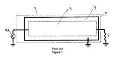
- a conventional one-half wavelength “Forward Wave” microstrip prior art coupler 3consisting of a, for example, rectangular conductive strip 5 upon a printed circuit board 7 having a separate ground plane 9 layer configured for these frequencies.
- One end of the conductive strip 5is connected to transceiver 42 and the other end is connected through terminating resistor 8 to ground plane 9 .
- the conductive strip 5 as shown in FIG. 1has a significant width due to RF design requirements imposed by the need to create acceptable frequency response characteristics.
- This type of prior art coupler 3has been used with UHF transponders that are relatively large compared to the extent of prior art coupler 3 .
- transponders 1As shown by FIGS. 2 a and 2 b , recently developed transponders 1 , designed for operation at UHF frequencies, have one dimension so significantly reduced, here for example a few millimeters wide, that they will be activated upon passage proximate the larger prior art coupler 3 by electro-magnetic power leakage 10 concentrated at either side edge of the conductive strip 5 of prior art coupler 3 .
- the two leakage regions “A” and “B” defined by electro-magnetic power leakage 10are small and relatively far apart, increasing system logical overhead and media conveyance positioning accuracy requirements. If the transponders 1 were placed close together, then multiple transponders 1 might be activated by the physically extensive one-half wavelength “Forward Wave” microstrip prior art coupler 3 .
- the minimum required spacing of these transponders 1 to isolate them, and thus the minimum size of media 11 (assuming that they are embedded one per label or media 11 on carrier substrate 13 )must be large relative to the size of the microstrip coupler 3 .
- Thisalso reduces the cost advantages of using the narrow dimensioned transponder(s) 1 within media 11 , as the media 11 must be much larger than the transponder 1 to achieve adequate RF isolation.
- FIG. 1is a top view of a prior art microstrip forward wave coupler.
- FIG. 2 ais a simplified cut-away side view of a transponder-coupler structure using a prior art forward wave coupler as shown in FIG. 1 , illustrating schematically locations where coupling with a narrow dimensioned transponder supplied in-line with other transponders on a carrier substrate may occur.
- FIG. 2 bis a partial cut-away top schematic view of the prior art forward wave coupler and carrier substrate with embedded transponders of FIG. 2 a.
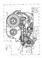
- FIG. 3is a side schematic view of a media printer according to one embodiment of the invention having an improved RFID interrogation system.
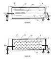
- FIG. 4 ais a top view of a coupler according to one embodiment of the invention.
- FIG. 4 bis a top view of a coupler according to another embodiment of the invention.
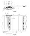
- FIG. 5 ais a simplified cut-away side view of a transponder-coupler structure using a coupler according to the invention, illustrating schematically the spaced apart areas where coupling with a narrow dimensioned transponder supplied in-line with other transponders on a carrier substrate may occur.
- FIG. 5 bis a partial cut-away top schematic view of the coupler according to the invention and carrier substrate with embedded transponders of FIG. 5 a.
- the present inventionconcerns apparatus and method which enables an RFID transceiver (sometimes termed herein an “interrogator”) to communicate selectively and exclusively with a single UHF transponder 1 when one or more other similar transponders are in close proximity, without the need for physical isolation or cumbersome shielded housings or chambers.
- an RFID transceiversometimes termed herein an “interrogator”
- the inventionis useful in the reading and or data loading of UHF transponders, for example on an assembly line, in distribution centers or warehouses where on-demand RFID labeling is required, and in a variety of other applications.
- a transponder or a number of transpondersare mounted or embedded on or in a label, ticket, tag, card or other media carried on a liner or carrier. It is often desirable to be able to print on the media before, after, or during communication with a transponder.
- this inventionis disclosed here in a specific embodiment for use with a direct thermal or thermal transfer printer, it may also be used with any type of spatially selective RFID interrogation device or other types of printers using other printing technologies, including inkjet, dot-matrix, and electro-photographic methods.
- a print stationmay be at a distance from the RFID transceiver; in others it may be necessary to accomplish the print function in the same target space occupied by the transponder when it is being interrogated.
- FIG. 3illustrates by way of example only an implementation of the invention in a thermal transfer media printer 16 in which both printing and transponder communication are accomplished, but at different locations in the media printer 16 .
- the media printer 16includes a printhead sub-assembly comprising a conventional thermal printhead 18 and platen roller 19 , as in a direct thermal printer for printing on thermally-sensitive media.
- a web 24 of media 11such as labels, tickets, tags or cards, is directed along a feed path 26 under the printhead 18 where on-demand printing of text, bar codes and/or graphics takes place under control of a computer or microprocessor (not shown).
- the media 11follows a media exit path 34 and may be peeled off the underlying carrier substrate 13 at a peeler bar 32 .
- the liner or carrier substrate 13 for the mediais guided out of the media printer 16 by a roller 36 where it exits the printer along a carrier exit path 38 .
- a ribbon supply roll 28delivers a thermal transfer ribbon (not shown for clarity) between printhead 14 and the media on web 24 . After use, the spent ribbon is collected on a take-up reel 22 .
- the media printer 16includes a transceiver 42 for generating RF communication signals that are fed to a frequency and spatially selective microstrip near field coupler 30 located proximate the media feed path 26 .
- the system(including transceiver 42 and near field coupler 30 ) forms a near field pattern in the location of a transponder operating region C (see FIG. 5A ).
- the systemis configured to establish at predetermined transceiver power levels a mutual coupling which exclusively activates and communicates with a single transponder 1 located in the transponder operating region C.
- the media printer 16When the media printer 16 is configured as a direct thermal printer, the heating elements form image dots by thermochromic color change in the heat sensitive media; when the media printer 16 is configured as a thermal transfer printer, then ink dots are formed by melting ink from the thermal transfer ribbon (not shown for clarity) delivered between printhead 18 and the media on web 24 from ribbon supply roll 28 . Patterns of printed dots thus form the desired information indicia on the media 11 , such as text, bar codes or graphics.
- the near field coupler 30according to the invention and its manner of operation will now be described with reference to FIGS. 4 a - 5 b .
- One embodiment of the near field coupler 30is configured for use, for example, with UHF RFID transponders.
- the RFID transponders 1may be bulk supplied on a carrier substrate 13 attached to or embedded within label, ticket, card or tag media 11 .
- the near field coupler 30comprises an array of lines 50 , as shown in FIGS. 4 a and 4 b .
- the near field coupler 30is configured as a segment of unmatched line 50 upon a dielectric substrate, for example a printed circuit board 7 , having a ground plane 9 formed on a spaced apart isolated layer, for example the reverse side of the printed circuit board 7 .
- One end of the array of lines 50is connected to the transceiver 42 ; the other end is connected to the ground plane 9 by means of terminating resistor 8 .
- Signals generated by the transceiver 42 passing along the transmission linegenerate a near field effect emanating from the transmission line edges that couples with a transponder 1 passing through the transponder operating region.
- Another description for the near field effectis “leaky”, as discussed in “Leaky Fields on Microstrip” L. O. McMillian et al. Progress in Electromagnetics Research, PIER 17, 323-337, 1997 and hereby incorporated by reference in the entirety.
- the prior rectangular conductive stripis therefore replaced with an array formed by a plurality of commonly fed and terminated, i.e. electrically parallel, line(s) 50 , as shown for example in FIGS. 4 a and 4 b .
- the plurality of lines 50therefore creates an array of leaky edges as shown in FIG. 5 a ; each leaky edge creating an electromagnetic power leakage 10 at several points within transponder operating region C.
- the resulting line arrayhas similar overall width to the prior solid microstrip coupler 3 and may be similarly tuned, by adjusting the length, spacing and dielectric properties between the line(s) 50 and the ground plane 9 as well as the number of line(s) 50 and or individual line widths, shapes and inter-spacing, to adjust the overall array as an integrated single electrical structure to have the desired frequency response characteristics and generate a combined near field effect corresponding to a desired transponder operating region.
- the transponder operating region C resulting from a near field coupler 30 according to the inventionis substantially uniform.
- narrow null gaps in the operational region Cmay occur, as illustrated by d, e, f, and g in FIG. 5 a .
- Simplified logic added to the media transport systemmay be used to move the media 11 forward a small increment, for example 1-2 millimeters if a transponder 1 in the transponder operating region C falls upon one of these null gaps and transponder communications is lost.
- the near field coupler 30useful for eliminating precision transponder placement requirements for media suppliers, complex transponder location and tracking logic in media supply systems, as well as any requirements for shielding or increased transponder placement tolerance requirements.
- the increased transponder operating region C provided by the present inventionallows users increased freedom to place embedded transponder(s) 1 in media 11 at desired locations, for example to avoid the printing degradation that may occur when the printhead encounters a media surface irregularity due to the presence of a RFID transponder 1 .
- the array of lines 50 of the near field coupler 30may be formed by a plurality of straight line(s) 50 as shown in FIG. 4 a .
- a zig-zag or wigglemay be applied to each line 50 , as shown for example in FIG. 4 b to reduce the appearance and/or depth of the field strength gaps d, e, f and g.
- zig-zagis defined as a characteristic of a line having an overall length characteristic, but a plurality of direction changes internal to the overall length of the line. The direction changes may, for example, be sharply defined or occur as smooth curves.
- a simplified transponder 1 read and or write systemmay be formed without printing capabilities by positioning a near field coupler 30 coupled to a transceiver 42 proximate a media conveyance 25 moving sequential transponders 1 through a transponder operating region C. This structure is also useful where the media 11 is unprinted, or printed upon at another location.
- the near field coupler 30is not limited to a dual plane structure.
- the near field coupler 30may be co-planar, i.e. the ground plane and the array of lines 50 may be located, electrically isolated from each other, in the same plane of a printed circuit board but on different traces.
- the lines 50need not be co-planar, but may form a 3-dimensional structure.
- the lines 50may be on multiple layers of a printed circuit board or formed as a wire frame of lines 50 without use of printed circuit board technology.
- the spatially-selective near field property and the lack of any other shielding requirements of the near field coupler 30 according to the inventionallows the economical addition of compact, spatially-selective transponder communication module in devices such as printer-encoders.
- the near field coupler 30may be configured to be selective exclusively for a single transponder located in the transponder operating region C, it is now possible by this invention to use a web 24 of media having transponders which are closely spaced on the web 24 , as shown for example in the figures of this specification.
- Prior to this inventionit was extremely difficult to communicate with just one electro-magnetically-coupled UHF transponder, which may have a wide number of different physical configurations, in a closely spaced series of transponders without simultaneously activating adjacent transponders.
- transponder 3prior art coupler 5 conductive strip 7 printed circuit board 8 terminating resistor 9 ground plane 10 electro-magnetic power leakage 11 media 13 carrier substrate 16 media printer 18 printhead 19 platen roller 22 take up reel 24 web 25 media conveyance 26 feed path 28 ribbon supply roll 30 near field coupler 32 tear bar 34 media exit path 36 roller 38 carrier exit path 42 transceiver 50 line
Landscapes
- Engineering & Computer Science (AREA)
- Physics & Mathematics (AREA)
- Health & Medical Sciences (AREA)
- Toxicology (AREA)
- Theoretical Computer Science (AREA)
- General Physics & Mathematics (AREA)
- Computer Vision & Pattern Recognition (AREA)
- Artificial Intelligence (AREA)
- Computer Networks & Wireless Communication (AREA)
- General Health & Medical Sciences (AREA)
- Electromagnetism (AREA)
- General Engineering & Computer Science (AREA)
- Near-Field Transmission Systems (AREA)
- Radar Systems Or Details Thereof (AREA)
- Input Circuits Of Receivers And Coupling Of Receivers And Audio Equipment (AREA)
- Accessory Devices And Overall Control Thereof (AREA)
Abstract
Description
| TABLE OF PARTS | |
| 1 | |
| 3 | |
| 5 | |
| 7 | printed |
| 8 | terminating |
| 9 | |
| 10 | electro- |
| 11 | |
| 13 | |
| 16 | |
| 18 | |
| 19 | |
| 22 | take up |
| 24 | |
| 25 | |
| 26 | |
| 28 | |
| 30 | |
| 32 | |
| 34 | |
| 36 | |
| 38 | |
| 42 | |
| 50 | line |
Claims (12)
Priority Applications (17)
| Application Number | Priority Date | Filing Date | Title |
|---|---|---|---|
| US10/604,996US7398054B2 (en) | 2003-08-29 | 2003-08-29 | Spatially selective UHF near field microstrip coupler device and RFID systems using device |
| US10/707,895US20050045724A1 (en) | 2003-08-29 | 2004-01-21 | Spatially Selective UHF Near Field Microstrip Coupler Device and RFID Systems Using Device |
| PCT/US2004/027832WO2005022445A2 (en) | 2003-08-29 | 2004-08-26 | Spatially selective uhf near field microstrip coupler device and rfid systems using device |
| PL10183755TPL2266808T3 (en) | 2003-08-29 | 2004-08-26 | Spatially selective UHF near field microstrip coupler device and RFID systems using device |
| AT07108946TATE555910T1 (en) | 2003-08-29 | 2004-08-26 | SATIALLY SELECTIVE UHF NEAR FIELD MICRO STRIP COUPLING DEVICE AND RFID SYSTEMS USING SUCH DEVICE |
| EP04782330.7AEP1660331B1 (en) | 2003-08-29 | 2004-08-26 | Printer with spatially selective uhf near field microstrip coupler device |
| EP10183731AEP2266807A1 (en) | 2003-08-29 | 2004-08-26 | Spatially selective UHF near field microstrip coupler device and RFID systems using device |
| EP07108946AEP1820659B1 (en) | 2003-08-29 | 2004-08-26 | Spatially selective UHF near field microstrip coupler device and RFID systems using device |
| EP10183780.5AEP2272680A3 (en) | 2003-08-29 | 2004-08-26 | Spatially selective UHF near field microstrip coupler device and RFID systems using device |
| ES07108946TES2391052T3 (en) | 2003-08-29 | 2004-08-26 | Spatially selective UHF near-field microcintas coupler device and RFID system using the device |
| CNB2004800287858ACN100464991C (en) | 2003-08-29 | 2004-08-26 | Printer, near field coupler, system including transceiver, and communication method |
| EP10183755.7AEP2266808B1 (en) | 2003-08-29 | 2004-08-26 | Spatially selective UHF near field microstrip coupler device and RFID systems using device |
| TW093125792ATWI250460B (en) | 2003-08-29 | 2004-08-27 | Spatially selective UHF near field microstrip coupler device and RFID systems using device |
| US12/133,801US7650114B2 (en) | 2003-08-29 | 2008-06-05 | Spatially selective UHF near field microstrip coupler device and RFID systems using device |
| US12/624,781US8160493B2 (en) | 2003-08-29 | 2009-11-24 | Spatially selective UHF near field microstrip coupler device and RFID systems using device |
| US13/422,950US8351959B2 (en) | 2003-08-29 | 2012-03-16 | Spatially selective UHF near field microstrip coupler device and RFID systems using device |
| US13/712,829US9852318B2 (en) | 2003-08-29 | 2012-12-12 | Spatially selective UHF near field microstrip coupler device and RFID systems using device |
Applications Claiming Priority (1)
| Application Number | Priority Date | Filing Date | Title |
|---|---|---|---|
| US10/604,996US7398054B2 (en) | 2003-08-29 | 2003-08-29 | Spatially selective UHF near field microstrip coupler device and RFID systems using device |
Related Child Applications (2)
| Application Number | Title | Priority Date | Filing Date |
|---|---|---|---|
| US10/707,895Continuation-In-PartUS20050045724A1 (en) | 2003-08-29 | 2004-01-21 | Spatially Selective UHF Near Field Microstrip Coupler Device and RFID Systems Using Device |
| US12/133,801DivisionUS7650114B2 (en) | 2003-08-29 | 2008-06-05 | Spatially selective UHF near field microstrip coupler device and RFID systems using device |
Publications (2)
| Publication Number | Publication Date |
|---|---|
| US20050045723A1 US20050045723A1 (en) | 2005-03-03 |
| US7398054B2true US7398054B2 (en) | 2008-07-08 |
Family
ID=34216249
Family Applications (6)
| Application Number | Title | Priority Date | Filing Date |
|---|---|---|---|
| US10/604,996Expired - LifetimeUS7398054B2 (en) | 2003-08-29 | 2003-08-29 | Spatially selective UHF near field microstrip coupler device and RFID systems using device |
| US10/707,895AbandonedUS20050045724A1 (en) | 2003-08-29 | 2004-01-21 | Spatially Selective UHF Near Field Microstrip Coupler Device and RFID Systems Using Device |
| US12/133,801Expired - LifetimeUS7650114B2 (en) | 2003-08-29 | 2008-06-05 | Spatially selective UHF near field microstrip coupler device and RFID systems using device |
| US12/624,781Expired - Fee RelatedUS8160493B2 (en) | 2003-08-29 | 2009-11-24 | Spatially selective UHF near field microstrip coupler device and RFID systems using device |
| US13/422,950Expired - Fee RelatedUS8351959B2 (en) | 2003-08-29 | 2012-03-16 | Spatially selective UHF near field microstrip coupler device and RFID systems using device |
| US13/712,829Active2026-04-22US9852318B2 (en) | 2003-08-29 | 2012-12-12 | Spatially selective UHF near field microstrip coupler device and RFID systems using device |
Family Applications After (5)
| Application Number | Title | Priority Date | Filing Date |
|---|---|---|---|
| US10/707,895AbandonedUS20050045724A1 (en) | 2003-08-29 | 2004-01-21 | Spatially Selective UHF Near Field Microstrip Coupler Device and RFID Systems Using Device |
| US12/133,801Expired - LifetimeUS7650114B2 (en) | 2003-08-29 | 2008-06-05 | Spatially selective UHF near field microstrip coupler device and RFID systems using device |
| US12/624,781Expired - Fee RelatedUS8160493B2 (en) | 2003-08-29 | 2009-11-24 | Spatially selective UHF near field microstrip coupler device and RFID systems using device |
| US13/422,950Expired - Fee RelatedUS8351959B2 (en) | 2003-08-29 | 2012-03-16 | Spatially selective UHF near field microstrip coupler device and RFID systems using device |
| US13/712,829Active2026-04-22US9852318B2 (en) | 2003-08-29 | 2012-12-12 | Spatially selective UHF near field microstrip coupler device and RFID systems using device |
Country Status (5)
| Country | Link |
|---|---|
| US (6) | US7398054B2 (en) |
| EP (4) | EP2266808B1 (en) |
| CN (1) | CN100464991C (en) |
| AT (1) | ATE555910T1 (en) |
| PL (1) | PL2266808T3 (en) |
Cited By (16)
| Publication number | Priority date | Publication date | Assignee | Title |
|---|---|---|---|---|
| US20050274799A1 (en)* | 2004-06-10 | 2005-12-15 | Zih Corp. | Apparatus and method for communicating with an RFID transponder |
| US20070147938A1 (en)* | 2005-12-13 | 2007-06-28 | Zih Corp. | Printer encoder adapted for positioning aboard a mobile unit |
| US20070262873A1 (en)* | 2006-03-09 | 2007-11-15 | Zih Corp. | Rfid uhf stripline antenna-coupler |
| US20080007457A1 (en)* | 2004-11-02 | 2008-01-10 | Sensomatic Electronics Corporation | Rfid Near Field Linear Antenna |
| US20080238606A1 (en)* | 2007-03-30 | 2008-10-02 | Zih Corp. | Near-Field Miniature Coupler |
| US20080298822A1 (en)* | 2007-05-30 | 2008-12-04 | Zih Corp. | System for processing media units and an associated media roll |
| US20090008448A1 (en)* | 2003-08-29 | 2009-01-08 | Zih Corp. | Spatially selective uhf near field microstrip coupler device and rfid systems using device |
| US20090072916A1 (en)* | 2006-12-27 | 2009-03-19 | Analogies S.A. | Integrated Circuit Distributed Oscillator |
| US20090152353A1 (en)* | 2007-12-18 | 2009-06-18 | Zih Corp. | Rfid near-field antenna and associated systems |
| US20090162123A1 (en)* | 2007-12-19 | 2009-06-25 | Zih Corp. | Platen incorporating an rfid coupling device |
| US20090231140A1 (en)* | 2008-02-05 | 2009-09-17 | Ls Industrial Systems Co., Ltd. | Radio frequency identification antenna and apparatus for managing items using the same |
| US20100285746A1 (en)* | 2009-05-11 | 2010-11-11 | Zih Corp. | Near field coupling devices and associated systems and methods |
| WO2011060300A2 (en) | 2009-11-13 | 2011-05-19 | Zih Corp. | Encoding module, associated encoding element, connector, printer-encoder and access control system |
| US8078103B2 (en) | 2005-10-31 | 2011-12-13 | Zih Corp. | Multi-element RFID coupler |
| US20130161382A1 (en)* | 2011-12-09 | 2013-06-27 | Avery Dennison Corporation | RFID Digital Print/Encode |
| US9296214B2 (en) | 2004-07-02 | 2016-03-29 | Zih Corp. | Thermal print head usage monitor and method for using the monitor |
Families Citing this family (38)
| Publication number | Priority date | Publication date | Assignee | Title |
|---|---|---|---|---|
| US7398926B1 (en)* | 2003-10-06 | 2008-07-15 | Applied Wireless Identifications Group, Inc. | Apparatus and method for programming an RFID transponder using a constrained field |
| JP3935162B2 (en)* | 2004-04-28 | 2007-06-20 | 東芝テック株式会社 | RF tag reader / writer and printer |
| ITMO20040245A1 (en)* | 2004-09-24 | 2004-12-24 | Meta System Spa | OBSTACLE DETECTION SYSTEM AND METHOD IN PARTICULAR FOR VEHICLE PARKING FACILITATION SYSTEMS. |
| KR101059872B1 (en)* | 2005-01-03 | 2011-08-29 | 삼성전자주식회사 | Communication collision prevention protocol using unique identifier |
| US7506813B2 (en)* | 2005-01-06 | 2009-03-24 | Quad/Graphics, Inc. | Resonator use in the print field |
| US7477152B2 (en)* | 2005-03-14 | 2009-01-13 | Avery Dennison Corporation | RFID application test systems and methods |
| US7411498B2 (en)* | 2005-04-07 | 2008-08-12 | Avery Dennison | RFID testing and classification systems and methods |
| US7295117B2 (en) | 2005-04-07 | 2007-11-13 | Avery Dennison | RFID device test thresholds systems and methods |
| US7298266B2 (en)* | 2005-05-09 | 2007-11-20 | Avery Dennison | RFID communication systems and methods |
| US7298267B2 (en)* | 2005-05-09 | 2007-11-20 | Avery Dennison | RFID test interface systems and methods |
| US7359823B2 (en) | 2005-05-25 | 2008-04-15 | Avery Dennison | RFID device variable test systems and methods |
| US9272805B2 (en) | 2005-08-19 | 2016-03-01 | Adasa Inc. | Systems, methods, and devices for commissioning wireless sensors |
| US8228198B2 (en)* | 2005-08-19 | 2012-07-24 | Adasa Inc. | Systems, methods, and devices for commissioning wireless sensors |
| US20100001848A1 (en)* | 2007-06-22 | 2010-01-07 | Mcallister Clarke | Secure Modular Applicators to Commission Wireless Sensors |
| US7551087B2 (en)* | 2005-08-19 | 2009-06-23 | Adasa, Inc. | Handheld and cartridge-fed applicator for commissioning wireless sensors |
| US8159349B2 (en)* | 2005-08-19 | 2012-04-17 | Adasa Inc. | Secure modular applicators to commission wireless sensors |
| US7830258B2 (en)* | 2005-08-19 | 2010-11-09 | Adasa, Inc. | Systems, methods, and devices for converting and commissioning wireless sensors |
| US7425887B2 (en)* | 2005-09-21 | 2008-09-16 | Zih Corporation | Multi-layered efficient RFID coupler |
| US7824118B2 (en)* | 2006-04-25 | 2010-11-02 | Toshiba Tec Kabushiki Kaisha | Printer comprising a flexible member extending over the antennas of RFID labels wound on a roll |
| JP4791883B2 (en)* | 2006-05-12 | 2011-10-12 | 株式会社東芝 | Antenna device and article management system |
| US20080074269A1 (en) | 2006-09-21 | 2008-03-27 | Zih Corp. | Rfid system and associated antenna-coupler |
| DE102006052517A1 (en)* | 2006-11-06 | 2008-05-08 | Bielomatik Leuze Gmbh + Co.Kg | Chip module for an RFID system |
| US20080117027A1 (en)* | 2006-11-16 | 2008-05-22 | Zih Corporation | Systems, methods, and associated rfid antennas for processing a plurality of transponders |
| US7832952B2 (en)* | 2007-03-21 | 2010-11-16 | Avery Dennison Corporation | High-frequency RFID printer |
| US8870478B2 (en)* | 2007-05-30 | 2014-10-28 | Zih Corp. | Media processing system and associated spindle |
| JP4851503B2 (en) | 2007-10-10 | 2012-01-11 | 三洋化成工業株式会社 | Method for producing fine particle dispersed polyol and method for producing polyurethane resin |
| US7843347B2 (en) | 2008-01-30 | 2010-11-30 | Intermac Ip Corp. | Near-field and far-field antenna-assembly and devices having same |
| US8314746B2 (en)* | 2008-04-02 | 2012-11-20 | Intermec Ip Corp. | Wireless encoder apparatus and methods |
| US8344959B2 (en)* | 2009-04-30 | 2013-01-01 | Nokia Corporation | Multiprotocol antenna for wireless systems |
| US20100279734A1 (en)* | 2009-04-30 | 2010-11-04 | Nokia Corporation | Multiprotocol Antenna For Wireless Systems |
| US8267494B2 (en)* | 2009-12-09 | 2012-09-18 | Hand Held Products, Inc. | Automatic RFID circuit tuning |
| JP5011405B2 (en)* | 2010-02-12 | 2012-08-29 | 東芝テック株式会社 | RF tag reader / writer |
| US8610638B2 (en) | 2011-01-17 | 2013-12-17 | Nokia Corporation | FM transmission using a RFID/NFC coil antenna |
| CN103310242B (en)* | 2012-03-14 | 2018-01-16 | 航天信息股份有限公司 | A kind of RFID asset management systems for having video signal monitoring and its assets management method |
| US9615153B2 (en)* | 2012-05-25 | 2017-04-04 | Avago Technologies General Ip (Singapore) Pte. Ltd. | System and method for applying an extended multipoint protocol to wireless access systems |
| WO2017088933A1 (en) | 2015-11-27 | 2017-06-01 | Sato Holdings Kabushiki Kaisha | Multi-layer electromagnetic coupler arrangement |
| CN107736015B (en)* | 2015-12-22 | 2021-02-19 | 索尼公司 | Image sensor, electronic device, control method, and program |
| DE102016113302A1 (en)* | 2016-07-19 | 2018-01-25 | Sick Ag | RFID device and method for communicating with at least one RFID transponder |
Citations (29)
| Publication number | Priority date | Publication date | Assignee | Title |
|---|---|---|---|---|
| US4509039A (en) | 1983-07-05 | 1985-04-02 | Minnesota Mining And Manufacturing Company | Shielded, closely spaced transmit-receiver antennas for electronic article surveillance system |
| EP0414628A2 (en) | 1989-08-25 | 1991-02-27 | George W. Kaltner | Individually fed multiloop antennas for electronic security systems |
| US5006812A (en)* | 1989-08-01 | 1991-04-09 | Rockwell International Corporation | Power amplifier with built-in test circuit |
| EP0568067A1 (en) | 1992-04-29 | 1993-11-03 | Texas Instruments Incorporated | RFID system with controlled charge |
| EP0568066A1 (en) | 1992-04-29 | 1993-11-03 | Texas Instruments Incorporated | A method of interrogating a plurality of transponders arranged in the transmission range of an interrogating device and transponders for use in the said method |
| US5278571A (en) | 1991-10-16 | 1994-01-11 | Tel Instrument Electronics Corp. | RF coupler for measuring RF parameters in the near-field |
| US5369381A (en) | 1990-05-29 | 1994-11-29 | U.S. Philips Corporation | Slow-wave transmission line of the microstrip type and circuit including such a line |
| US5373266A (en) | 1993-11-09 | 1994-12-13 | The United States Of America As Represented By The Secreatry Of The Army | Microstrip directional coupler |
| EP0704815A2 (en) | 1994-09-30 | 1996-04-03 | Hughes Identification Devices, Inc. | High field programmable transponder system and method |
| US5777586A (en) | 1993-03-17 | 1998-07-07 | Luxon; Norval N. | Radiation shielding and range extending antenna assembly |
| GB2321551A (en) | 1996-03-22 | 1998-07-29 | John Wolfgang Halpern | Reading smartcards |
| DE9321478U1 (en) | 1992-08-01 | 1998-08-27 | Diehl Ident GmbH, 90478 Nürnberg | Device for inductive high-frequency interrogation of identification labels |
| US5838253A (en) | 1995-05-17 | 1998-11-17 | Accu-Sort Systems, Inc. | Radio frequency identification label |
| US6067475A (en)* | 1998-11-05 | 2000-05-23 | Urologix, Inc. | Microwave energy delivery system including high performance dual directional coupler for precisely measuring forward and reverse microwave power during thermal therapy |
| US6104291A (en) | 1998-01-09 | 2000-08-15 | Intermec Ip Corp. | Method and apparatus for testing RFID tags |
| US6181287B1 (en)* | 1997-03-10 | 2001-01-30 | Precision Dynamics Corporation | Reactively coupled elements in circuits on flexible substrates |
| US6246326B1 (en) | 1999-05-05 | 2001-06-12 | Intermec Ip Corp. | Performance optimized smart label printer |
| US6267521B1 (en) | 1995-09-22 | 2001-07-31 | Eltron International, Inc. | Computer driven printer with a stripper roller and latching assembly |
| US6392544B1 (en) | 2000-09-25 | 2002-05-21 | Motorola, Inc. | Method and apparatus for selectively activating radio frequency identification tags that are in close proximity |
| US6409401B1 (en)* | 2000-03-30 | 2002-06-25 | Zih Corp. | Portable printer with RFID encoder |
| EP1224607A1 (en) | 1999-10-18 | 2002-07-24 | Lucatron AG | Method for selecting and writing into rfid-transponders |
| EP1233367A2 (en) | 2001-02-09 | 2002-08-21 | Omron Corporation | Antenna apparatus |
| US6473028B1 (en) | 1999-04-07 | 2002-10-29 | Stmicroelectronics S.A. | Detection of the distance between an electromagnetic transponder and a terminal |
| US20020167397A1 (en) | 1999-07-08 | 2002-11-14 | Kursat Eroglu | Method and apparatus for verifying rfid tags |
| US6527356B1 (en) | 2000-06-02 | 2003-03-04 | Eastman Kodak Company | Printer capable of forming an image on a receiver substrate according to type of receiver substrate and a method of assembling the printer |
| JP2003132330A (en) | 2001-10-25 | 2003-05-09 | Sato Corp | RFID label printer |
| US20040178267A1 (en) | 2003-03-11 | 2004-09-16 | Zebra Technologies Corporation | System and Method for Selective Communication with RFID Transponders |
| US20040195319A1 (en)* | 2003-04-03 | 2004-10-07 | Forster Ian J. | RFID device detection system and method |
| US7023391B2 (en)* | 2000-05-17 | 2006-04-04 | Stmicroelectronics S.A. | Electromagnetic field generation antenna for a transponder |
Family Cites Families (67)
| Publication number | Priority date | Publication date | Assignee | Title |
|---|---|---|---|---|
| US3760278A (en) | 1970-12-23 | 1973-09-18 | Thomson Csf | Limited range radiocommunication system |
| US3742319A (en)* | 1971-03-08 | 1973-06-26 | Communications Transistor Corp | R f power transistor |
| US4371876A (en)* | 1978-05-04 | 1983-02-01 | Motorola Inc. | Slot array antenna having a complex impedance termination and method of fabrication |
| DE69022467T2 (en) | 1989-04-21 | 1996-02-08 | Marconi Instruments Ltd | Modulation of adjacent channels. |
| US5317646A (en) | 1992-03-24 | 1994-05-31 | Xerox Corporation | Automated method for creating templates in a forms recognition and processing system |
| FR2723654B1 (en)* | 1994-08-10 | 1996-10-11 | Gemplus Card Int | ELECTRONIC LABEL AND SYSTEM FOR CONTACTLESS IDENTIFICATION OF OBJECTS, PARTICULARLY METALLIC OBJECTS. |
| EP0704928A3 (en)* | 1994-09-30 | 1998-08-05 | HID Corporation | RF transponder system with parallel resonant interrogation and series resonant response |
| DE69524381T2 (en) | 1995-03-23 | 2002-08-14 | Agfa-Gevaert N.V., Mortsel | Parallel processing of the data stream of the page description language |
| US5521601A (en) | 1995-04-21 | 1996-05-28 | International Business Machines Corporation | Power-efficient technique for multiple tag discrimination |
| US5982877A (en)* | 1995-06-19 | 1999-11-09 | Nippon Telegraph And Telephone Corporation | Communications system using portable recording medium |
| JP3123900B2 (en) | 1995-06-30 | 2001-01-15 | 三洋電機株式会社 | Digital cordless telephone equipment |
| JP3693725B2 (en) | 1995-11-24 | 2005-09-07 | 株式会社日本自動車部品総合研究所 | Automatic response system using transponder |
| US6466131B1 (en)* | 1996-07-30 | 2002-10-15 | Micron Technology, Inc. | Radio frequency data communications device with adjustable receiver sensitivity and method |
| US6802659B2 (en) | 1996-08-07 | 2004-10-12 | Mats Cremon | Arrangement for automatic setting of programmable devices and materials therefor |
| US5798266A (en)* | 1996-08-27 | 1998-08-25 | K-Quay Enterprises, Llc | Methods and kits for obtaining and assaying mammary fluid samples for breast diseases, including cancer |
| US6012083A (en) | 1996-09-24 | 2000-01-04 | Ricoh Company Ltd. | Method and apparatus for document processing using agents to process transactions created based on document content |
| US5983243A (en) | 1996-10-31 | 1999-11-09 | International Business Machines Corporation | Data processing system and method for Preparing a presentation-ready document that produces separate images of fixed and variable data and a bookticket specifying an arrangement of such images |
| US5926133A (en)* | 1997-07-21 | 1999-07-20 | Denso Corporation | Differentially corrected position location system and method for mobile communication networks |
| US6215402B1 (en)* | 1998-03-13 | 2001-04-10 | Intermec Ip Corp. | Radio frequency identification transponder employing patch antenna |
| US6118379A (en)* | 1997-12-31 | 2000-09-12 | Intermec Ip Corp. | Radio frequency identification transponder having a spiral antenna |
| US6154137A (en)* | 1998-06-08 | 2000-11-28 | 3M Innovative Properties Company | Identification tag with enhanced security |
| US6424262B2 (en)* | 1998-08-14 | 2002-07-23 | 3M Innovative Properties Company | Applications for radio frequency identification systems |
| JP2000082277A (en)* | 1998-09-04 | 2000-03-21 | Sony Corp | Device corresponding to recording medium |
| DE19846295B4 (en)* | 1998-10-07 | 2008-04-24 | Kabushiki Kaisha Sato | Printer with a device for driving transponder chips |
| US6645327B2 (en)* | 1999-04-21 | 2003-11-11 | Intermec Ip Corp. | RF tag application system |
| US6985754B1 (en)* | 1999-04-26 | 2006-01-10 | Nokia Mobile Phones Limited | Radio terminal for browsing the internet |
| US7204652B2 (en)* | 1999-06-16 | 2007-04-17 | Vanguard Identification Systems, Inc. | Printed planar radio frequency identification elements |
| US6938976B2 (en) | 1999-06-16 | 2005-09-06 | Eastman Kodak Company | Printer and method therefor adapted to sense data uniquely associated with a consumable loaded into the printer |
| US6236314B1 (en)* | 1999-09-02 | 2001-05-22 | Micron Technology, Inc. | Transponder modules, RF tagging system, method of operating a transponder module and methods of tagging an object having a conductive surface |
| GB2355976B (en) | 1999-11-08 | 2003-08-06 | Pankhurst Design & Development | Holder for a disc having a central aperture |
| FR2800894B1 (en) | 1999-11-08 | 2003-05-02 | Commissariat Energie Atomique | METHOD AND SYSTEM FOR EXCHANGING INFORMATION BETWEEN A INTERROGATION DEVICE AND ANSWERING DEVICES TAKING INTO ACCOUNT OF THE SURROUNDING NOISE LEVEL |
| US6486769B1 (en) | 1999-12-22 | 2002-11-26 | Intermec Ip Corp. | Method and system for automatic adjustment and diagnosis of radio frequency identification systems using programmable checktags |
| US6593853B1 (en)* | 2000-02-18 | 2003-07-15 | Brady Worldwide, Inc. | RFID label printing system |
| US6346881B1 (en) | 2000-03-01 | 2002-02-12 | Samsys Technologies Inc. | Tag evaluation module for radio frequency identification (RFID) systems |
| US6819243B2 (en)* | 2000-04-03 | 2004-11-16 | Mikko Keskilammi | Method and apparatus for identifying bulk goods, preferably roll-like bulk goods |
| US6750771B1 (en)* | 2000-08-10 | 2004-06-15 | Savi Technology, Inc. | Antenna system and method for reading low frequency tags |
| US6724309B2 (en)* | 2000-11-03 | 2004-04-20 | Excel Corporation | Method and apparatus for tracking carcasses |
| DE10124222A1 (en) | 2001-05-18 | 2002-11-21 | Atmel Germany Gmbh | Method for matching an antenna resonant circuit of a passive transponder |
| US20030061947A1 (en)* | 2001-10-01 | 2003-04-03 | Hohberger Clive P. | Method and apparatus for associating on demand certain selected media and value-adding elements |
| US6969134B2 (en) | 2001-10-01 | 2005-11-29 | Zih Corp. | Printer or other media processor with on-demand selective media converter |
| US6837427B2 (en)* | 2001-11-21 | 2005-01-04 | Goliath Solutions, Llc. | Advertising compliance monitoring system |
| US7215976B2 (en) | 2001-11-30 | 2007-05-08 | Symbol Technologies, Inc. | RFID device, system and method of operation including a hybrid backscatter-based RFID tag protocol compatible with RFID, bluetooth and/or IEEE 802.11x infrastructure |
| GB0205046D0 (en)* | 2002-03-05 | 2002-04-17 | Bitarts Ltd | Security arrangement |
| US7204425B2 (en)* | 2002-03-18 | 2007-04-17 | Precision Dynamics Corporation | Enhanced identification appliance |
| JP2003348659A (en)* | 2002-05-28 | 2003-12-05 | Pioneer Electronic Corp | Apparatus and method for detecting mobile phone left behind |
| EP1394719B1 (en) | 2002-09-02 | 2007-05-30 | EM Microelectronic-Marin SA | Adaptation of the transmission and receiving characteristic of a RFID reader dependent on the electromagnetic background noise |
| DE10251465A1 (en) | 2002-11-05 | 2004-05-19 | Siemens Ag | Balancing mobile communications terminal transmission power involves dividing standard mobile radio frequency range into frequency intervals, carrying out power balancing for at least some intervals |
| US7023341B2 (en) | 2003-02-03 | 2006-04-04 | Ingrid, Inc. | RFID reader for a security network |
| EP1473885A1 (en) | 2003-04-30 | 2004-11-03 | Motorola, Inc. | Wireless communication unit and method for power saving with a power aware link adaption function |
| US7120987B2 (en)* | 2003-08-05 | 2006-10-17 | Avery Dennison Corporation | Method of making RFID device |
| US7398054B2 (en)* | 2003-08-29 | 2008-07-08 | Zih Corp. | Spatially selective UHF near field microstrip coupler device and RFID systems using device |
| EP1660331B1 (en) | 2003-08-29 | 2019-07-24 | Zebra Technologies Corporation | Printer with spatially selective uhf near field microstrip coupler device |
| US20050058483A1 (en)* | 2003-09-12 | 2005-03-17 | Chapman Theodore A. | RFID tag and printer system |
| US7026935B2 (en) | 2003-11-10 | 2006-04-11 | Impinj, Inc. | Method and apparatus to configure an RFID system to be adaptable to a plurality of environmental conditions |
| US7158037B2 (en) | 2004-03-22 | 2007-01-02 | Avery Dennison Corporation | Low cost method of producing radio frequency identification tags with straps without antenna patterning |
| US7606535B2 (en) | 2004-04-01 | 2009-10-20 | Harris Stratex Networks, Inc. | Modular wide-range transceiver |
| US8596532B2 (en)* | 2004-06-10 | 2013-12-03 | Zih Corp. | Apparatus and method for communicating with an RFID transponder |
| US8174383B1 (en)* | 2004-08-26 | 2012-05-08 | Avante International Technology, Inc. | System and method for operating a synchronized wireless network |
| US7190270B2 (en)* | 2004-11-05 | 2007-03-13 | Zih Corp. | System and method for detecting transponders used with printer media |
| US7425887B2 (en)* | 2005-09-21 | 2008-09-16 | Zih Corporation | Multi-layered efficient RFID coupler |
| US7629929B2 (en)* | 2005-09-26 | 2009-12-08 | Electronics And Telecommunications Research Institute | Antenna using proximity-coupled feed method, RFID tag having the same, and antenna impedance matching method thereof |
| US8078103B2 (en)* | 2005-10-31 | 2011-12-13 | Zih Corp. | Multi-element RFID coupler |
| KR20090052411A (en)* | 2007-11-21 | 2009-05-26 | 엘지이노텍 주식회사 | Location Tracking System Using Near Field Communication |
| US8120486B2 (en)* | 2008-06-10 | 2012-02-21 | Symbol Technologies, Inc. | Methods and systems for tracking RFID devices |
| US20100177080A1 (en)* | 2009-01-13 | 2010-07-15 | Metrologic Instruments, Inc. | Electronic-ink signage device employing thermal packaging for outdoor weather applications |
| US20100177707A1 (en)* | 2009-01-13 | 2010-07-15 | Metrologic Instruments, Inc. | Method and apparatus for increasing the SNR at the RF antennas of wireless end-devices on a wireless communication network, while minimizing the RF power transmitted by the wireless coordinator and routers |
| US9396447B2 (en)* | 2013-03-15 | 2016-07-19 | Codex Corporation | Systems and methods for monitoring a headcount |
- 2003
- 2003-08-29USUS10/604,996patent/US7398054B2/ennot_activeExpired - Lifetime
- 2004
- 2004-01-21USUS10/707,895patent/US20050045724A1/ennot_activeAbandoned
- 2004-08-26CNCNB2004800287858Apatent/CN100464991C/ennot_activeExpired - Lifetime
- 2004-08-26EPEP10183755.7Apatent/EP2266808B1/ennot_activeExpired - Lifetime
- 2004-08-26ATAT07108946Tpatent/ATE555910T1/enactive
- 2004-08-26EPEP07108946Apatent/EP1820659B1/ennot_activeExpired - Lifetime
- 2004-08-26EPEP10183731Apatent/EP2266807A1/ennot_activeWithdrawn
- 2004-08-26PLPL10183755Tpatent/PL2266808T3/enunknown
- 2004-08-26EPEP10183780.5Apatent/EP2272680A3/ennot_activeWithdrawn
- 2008
- 2008-06-05USUS12/133,801patent/US7650114B2/ennot_activeExpired - Lifetime
- 2009
- 2009-11-24USUS12/624,781patent/US8160493B2/ennot_activeExpired - Fee Related
- 2012
- 2012-03-16USUS13/422,950patent/US8351959B2/ennot_activeExpired - Fee Related
- 2012-12-12USUS13/712,829patent/US9852318B2/enactiveActive
Patent Citations (30)
| Publication number | Priority date | Publication date | Assignee | Title |
|---|---|---|---|---|
| US4509039A (en) | 1983-07-05 | 1985-04-02 | Minnesota Mining And Manufacturing Company | Shielded, closely spaced transmit-receiver antennas for electronic article surveillance system |
| US5006812A (en)* | 1989-08-01 | 1991-04-09 | Rockwell International Corporation | Power amplifier with built-in test circuit |
| EP0414628A2 (en) | 1989-08-25 | 1991-02-27 | George W. Kaltner | Individually fed multiloop antennas for electronic security systems |
| US5369381A (en) | 1990-05-29 | 1994-11-29 | U.S. Philips Corporation | Slow-wave transmission line of the microstrip type and circuit including such a line |
| US5278571A (en) | 1991-10-16 | 1994-01-11 | Tel Instrument Electronics Corp. | RF coupler for measuring RF parameters in the near-field |
| EP0568067A1 (en) | 1992-04-29 | 1993-11-03 | Texas Instruments Incorporated | RFID system with controlled charge |
| EP0568066A1 (en) | 1992-04-29 | 1993-11-03 | Texas Instruments Incorporated | A method of interrogating a plurality of transponders arranged in the transmission range of an interrogating device and transponders for use in the said method |
| DE9321478U1 (en) | 1992-08-01 | 1998-08-27 | Diehl Ident GmbH, 90478 Nürnberg | Device for inductive high-frequency interrogation of identification labels |
| US5777586A (en) | 1993-03-17 | 1998-07-07 | Luxon; Norval N. | Radiation shielding and range extending antenna assembly |
| US5373266A (en) | 1993-11-09 | 1994-12-13 | The United States Of America As Represented By The Secreatry Of The Army | Microstrip directional coupler |
| EP0704815A2 (en) | 1994-09-30 | 1996-04-03 | Hughes Identification Devices, Inc. | High field programmable transponder system and method |
| US5838253A (en) | 1995-05-17 | 1998-11-17 | Accu-Sort Systems, Inc. | Radio frequency identification label |
| US6267521B1 (en) | 1995-09-22 | 2001-07-31 | Eltron International, Inc. | Computer driven printer with a stripper roller and latching assembly |
| GB2321551A (en) | 1996-03-22 | 1998-07-29 | John Wolfgang Halpern | Reading smartcards |
| US6181287B1 (en)* | 1997-03-10 | 2001-01-30 | Precision Dynamics Corporation | Reactively coupled elements in circuits on flexible substrates |
| US6104291A (en) | 1998-01-09 | 2000-08-15 | Intermec Ip Corp. | Method and apparatus for testing RFID tags |
| US6067475A (en)* | 1998-11-05 | 2000-05-23 | Urologix, Inc. | Microwave energy delivery system including high performance dual directional coupler for precisely measuring forward and reverse microwave power during thermal therapy |
| US6473028B1 (en) | 1999-04-07 | 2002-10-29 | Stmicroelectronics S.A. | Detection of the distance between an electromagnetic transponder and a terminal |
| US6246326B1 (en) | 1999-05-05 | 2001-06-12 | Intermec Ip Corp. | Performance optimized smart label printer |
| US20020167397A1 (en) | 1999-07-08 | 2002-11-14 | Kursat Eroglu | Method and apparatus for verifying rfid tags |
| EP1224607A1 (en) | 1999-10-18 | 2002-07-24 | Lucatron AG | Method for selecting and writing into rfid-transponders |
| US6409401B1 (en)* | 2000-03-30 | 2002-06-25 | Zih Corp. | Portable printer with RFID encoder |
| US7023391B2 (en)* | 2000-05-17 | 2006-04-04 | Stmicroelectronics S.A. | Electromagnetic field generation antenna for a transponder |
| US6527356B1 (en) | 2000-06-02 | 2003-03-04 | Eastman Kodak Company | Printer capable of forming an image on a receiver substrate according to type of receiver substrate and a method of assembling the printer |
| US20030067504A1 (en) | 2000-06-02 | 2003-04-10 | Spurr Robert W. | Printer capable of forming an image on a receiver substrate according to type of receiver substrate and a method of assembling the printer |
| US6392544B1 (en) | 2000-09-25 | 2002-05-21 | Motorola, Inc. | Method and apparatus for selectively activating radio frequency identification tags that are in close proximity |
| EP1233367A2 (en) | 2001-02-09 | 2002-08-21 | Omron Corporation | Antenna apparatus |
| JP2003132330A (en) | 2001-10-25 | 2003-05-09 | Sato Corp | RFID label printer |
| US20040178267A1 (en) | 2003-03-11 | 2004-09-16 | Zebra Technologies Corporation | System and Method for Selective Communication with RFID Transponders |
| US20040195319A1 (en)* | 2003-04-03 | 2004-10-07 | Forster Ian J. | RFID device detection system and method |
Non-Patent Citations (11)
| Title |
|---|
| International Search Report for US2004/027832, dated Dec. 30, 2004. |
| International Search Report PCT/US2004/027832, dated May 6, 2005 and Written Opinion. |
| K.C. Gupta, Microstrip Lines and Slotlines, 1996, Artech House Publishers, USA. |
| Maloratsky, Couplers Shrinks HF/VHF/UHF Designs, Microwaves & RF, pp. 93-98, Jun. 2000, USA. |
| Maloratsky, Design Regular-And Irregular-Print Coupled Lines, Microwaves & RF, pp. 97-106, Sep. 2000, USA. |
| Maloratsky, Improve BPF Performance with Wiggly Coupled Lines, Microwaves & RF, pp. 53-62, Apr. 2002, USA. |
| Maloratsky, Reviewing the Basics of Mocrostrip Lines, Microwaves & RF, pp. 79-88, Mar. 2000, USA. |
| Maloratsky, Reviewing the Basics of Suspended Striplines, Microwave Journal, Oct. 2002, USA. |
| Maloratsky, The Basics of Print Reciprocal Dividers/Combiners, Microwave Journal, Sep. 2000, USA. |
| Maloratsky, Understand the Basics of Microstrip Directional Couplers, Microwaves & RF, pp. 79-94, Feb. 2001, USA. |
| McMillan et al., Leaky Fields on Microstrip, Progress in Electomagnetics Research, PIER 17, pp. 323-377, 1997, USA. |
Cited By (51)
| Publication number | Priority date | Publication date | Assignee | Title |
|---|---|---|---|---|
| US20090008448A1 (en)* | 2003-08-29 | 2009-01-08 | Zih Corp. | Spatially selective uhf near field microstrip coupler device and rfid systems using device |
| US7650114B2 (en)* | 2003-08-29 | 2010-01-19 | Zih Corp. | Spatially selective UHF near field microstrip coupler device and RFID systems using device |
| US9852318B2 (en) | 2003-08-29 | 2017-12-26 | Zih Corp. | Spatially selective UHF near field microstrip coupler device and RFID systems using device |
| US8351959B2 (en) | 2003-08-29 | 2013-01-08 | Zih Corp. | Spatially selective UHF near field microstrip coupler device and RFID systems using device |
| US8160493B2 (en) | 2003-08-29 | 2012-04-17 | Zih Corp. | Spatially selective UHF near field microstrip coupler device and RFID systems using device |
| US8544740B2 (en) | 2004-06-10 | 2013-10-01 | Zih Corp. | Apparatus and method for communicating with an RFID transponder |
| US20140132399A1 (en)* | 2004-06-10 | 2014-05-15 | Zih Corp. | Apparatus and Method for Communicating with an RFID Transponder |
| US8596532B2 (en) | 2004-06-10 | 2013-12-03 | Zih Corp. | Apparatus and method for communicating with an RFID transponder |
| US9613242B2 (en)* | 2004-06-10 | 2017-04-04 | Zih Corp. | Apparatus and method for communicating with an RFID transponder |
| US20050274799A1 (en)* | 2004-06-10 | 2005-12-15 | Zih Corp. | Apparatus and method for communicating with an RFID transponder |
| US9296214B2 (en) | 2004-07-02 | 2016-03-29 | Zih Corp. | Thermal print head usage monitor and method for using the monitor |
| US10315438B2 (en) | 2004-07-02 | 2019-06-11 | Zebra Technologies Corporation | Thermal print head usage monitor and method for using the monitor |
| US20080007457A1 (en)* | 2004-11-02 | 2008-01-10 | Sensomatic Electronics Corporation | Rfid Near Field Linear Antenna |
| US7612719B2 (en)* | 2004-11-02 | 2009-11-03 | Sensormatic Electronics Corporation | RFID near field linear antenna |
| US8306474B2 (en)* | 2005-10-31 | 2012-11-06 | Zih Corp. | Multi-element RFID coupler |
| US8078103B2 (en) | 2005-10-31 | 2011-12-13 | Zih Corp. | Multi-element RFID coupler |
| US9391675B2 (en) | 2005-10-31 | 2016-07-12 | Zih Corp. | Multi-element RFID coupler |
| US20120108170A1 (en)* | 2005-10-31 | 2012-05-03 | Zih Corp. | Multi-element rfid coupler |
| US20070147938A1 (en)* | 2005-12-13 | 2007-06-28 | Zih Corp. | Printer encoder adapted for positioning aboard a mobile unit |
| US9849694B2 (en) | 2005-12-13 | 2017-12-26 | Zih Corp. | Printer encoder adapted for positioning aboard a mobile unit |
| US20110074553A1 (en)* | 2005-12-13 | 2011-03-31 | Zih Corp. | Printer encoder adapted for positioning aboard a mobile unit |
| US8358246B2 (en) | 2006-03-09 | 2013-01-22 | Zih Corp. | RFID UHF stripline antenna-coupler |
| US20070262873A1 (en)* | 2006-03-09 | 2007-11-15 | Zih Corp. | Rfid uhf stripline antenna-coupler |
| US8149066B2 (en) | 2006-12-27 | 2012-04-03 | Analogies, Inc. | Integrated circuit distributed oscillator |
| US20090072916A1 (en)* | 2006-12-27 | 2009-03-19 | Analogies S.A. | Integrated Circuit Distributed Oscillator |
| US20080238606A1 (en)* | 2007-03-30 | 2008-10-02 | Zih Corp. | Near-Field Miniature Coupler |
| US7839287B2 (en)* | 2007-03-30 | 2010-11-23 | Zih Corp. | Near-field miniature coupler |
| US9524460B2 (en) | 2007-05-30 | 2016-12-20 | Zih Corp. | System for processing media units and an associated media roll |
| US20080298822A1 (en)* | 2007-05-30 | 2008-12-04 | Zih Corp. | System for processing media units and an associated media roll |
| US20090152353A1 (en)* | 2007-12-18 | 2009-06-18 | Zih Corp. | Rfid near-field antenna and associated systems |
| US9108434B2 (en) | 2007-12-18 | 2015-08-18 | Zih Corp. | RFID near-field antenna and associated systems |
| US20090162123A1 (en)* | 2007-12-19 | 2009-06-25 | Zih Corp. | Platen incorporating an rfid coupling device |
| US9415611B2 (en)* | 2007-12-19 | 2016-08-16 | Zih Corp. | Platen incorporating an RFID coupling device |
| US20090231140A1 (en)* | 2008-02-05 | 2009-09-17 | Ls Industrial Systems Co., Ltd. | Radio frequency identification antenna and apparatus for managing items using the same |
| US9660701B2 (en) | 2009-05-11 | 2017-05-23 | Zih Corp. | Near field coupling devices and associated systems and methods |
| US8254833B2 (en) | 2009-05-11 | 2012-08-28 | Zih Corp. | Near field coupling devices and associated systems and methods |
| US8791874B2 (en) | 2009-05-11 | 2014-07-29 | Zih Corp. | Near field coupling devices and associated systems and methods |
| US8565677B2 (en) | 2009-05-11 | 2013-10-22 | Zih Corp. | Near field coupling devices and associated systems and methods |
| USRE46223E1 (en) | 2009-05-11 | 2016-11-29 | Zih Corp. | Near field coupling devices and associated systems and methods |
| EP3528174A1 (en) | 2009-05-11 | 2019-08-21 | Zebra Technologies Corporation | Near field coupling device and associated system and method |
| US20100285746A1 (en)* | 2009-05-11 | 2010-11-11 | Zih Corp. | Near field coupling devices and associated systems and methods |
| US9994043B2 (en) | 2009-05-11 | 2018-06-12 | Zih Corp. | Near field coupling devices and associated systems and methods |
| EP2963586A1 (en) | 2009-05-11 | 2016-01-06 | ZIH Corp. | Near field coupling device and associated system and method |
| US10325194B2 (en) | 2009-11-13 | 2019-06-18 | Zebra Technologies Corporation | Encoding module, associated encoding element, connector, printer-encoder and access control system |
| US8878652B2 (en) | 2009-11-13 | 2014-11-04 | Zih Corp. | Encoding module, associated encoding element, connector, printer-encoder and access control system |
| US9639721B2 (en) | 2009-11-13 | 2017-05-02 | Zih Corp. | Encoding module, associated encoding element, connector, printer-encoder and access control system |
| WO2011060300A2 (en) | 2009-11-13 | 2011-05-19 | Zih Corp. | Encoding module, associated encoding element, connector, printer-encoder and access control system |
| US20110115611A1 (en)* | 2009-11-13 | 2011-05-19 | Tsirline Boris Y | Encoding module, associated encoding element, connector, printer-encoder and access control system |
| US20130161382A1 (en)* | 2011-12-09 | 2013-06-27 | Avery Dennison Corporation | RFID Digital Print/Encode |
| US10410101B2 (en)* | 2011-12-09 | 2019-09-10 | Avery Dennison Retail Information Services, Llc | RFID digital print/encode |
| US20190392272A1 (en)* | 2011-12-09 | 2019-12-26 | Avery Dennison Retail Information Services, Llc | Rfid digital print/encode |
Also Published As
| Publication number | Publication date |
|---|---|
| EP1820659A3 (en) | 2009-12-16 |
| EP2266807A1 (en) | 2010-12-29 |
| US7650114B2 (en) | 2010-01-19 |
| PL2266808T3 (en) | 2014-12-31 |
| CN100464991C (en) | 2009-03-04 |
| US8160493B2 (en) | 2012-04-17 |
| EP2272680A3 (en) | 2018-02-28 |
| US20050045724A1 (en) | 2005-03-03 |
| US20100067054A1 (en) | 2010-03-18 |
| US20090008448A1 (en) | 2009-01-08 |
| ATE555910T1 (en) | 2012-05-15 |
| US20140002243A1 (en) | 2014-01-02 |
| EP2272680A2 (en) | 2011-01-12 |
| EP1820659B1 (en) | 2012-05-02 |
| US20050045723A1 (en) | 2005-03-03 |
| US8351959B2 (en) | 2013-01-08 |
| US20120176224A1 (en) | 2012-07-12 |
| EP2266808B1 (en) | 2014-07-02 |
| EP2266808A1 (en) | 2010-12-29 |
| CN1863681A (en) | 2006-11-15 |
| EP1820659A2 (en) | 2007-08-22 |
| US9852318B2 (en) | 2017-12-26 |
Similar Documents
| Publication | Publication Date | Title |
|---|---|---|
| US7398054B2 (en) | Spatially selective UHF near field microstrip coupler device and RFID systems using device | |
| US8544740B2 (en) | Apparatus and method for communicating with an RFID transponder | |
| US7504950B2 (en) | System and method for continuous RFID encoding | |
| EP2261835B1 (en) | Multi-element RFID coupler | |
| US6848616B2 (en) | System and method for selective communication with RFID transponders | |
| US7489243B2 (en) | System and method for detecting transponders used with printer media | |
| US9660701B2 (en) | Near field coupling devices and associated systems and methods | |
| EP1660331B1 (en) | Printer with spatially selective uhf near field microstrip coupler device |
Legal Events
| Date | Code | Title | Description |
|---|---|---|---|
| AS | Assignment | Owner name:ZIH CORP.,, BERMUDA Free format text:ASSIGNMENT OF ASSIGNORS INTEREST;ASSIGNORS:TSIRLINE, BORIS Y.;HOHBERGER, CLIVE;GAWELCZYK, ROBERT;AND OTHERS;REEL/FRAME:014537/0878 Effective date:20030829 | |
| STCF | Information on status: patent grant | Free format text:PATENTED CASE | |
| FPAY | Fee payment | Year of fee payment:4 | |
| AS | Assignment | Owner name:MORGAN STANLEY SENIOR FUNDING, INC. AS THE COLLATERAL AGENT, MARYLAND Free format text:SECURITY AGREEMENT;ASSIGNORS:ZIH CORP.;LASER BAND, LLC;ZEBRA ENTERPRISE SOLUTIONS CORP.;AND OTHERS;REEL/FRAME:034114/0270 Effective date:20141027 Owner name:MORGAN STANLEY SENIOR FUNDING, INC. AS THE COLLATE Free format text:SECURITY AGREEMENT;ASSIGNORS:ZIH CORP.;LASER BAND, LLC;ZEBRA ENTERPRISE SOLUTIONS CORP.;AND OTHERS;REEL/FRAME:034114/0270 Effective date:20141027 | |
| FPAY | Fee payment | Year of fee payment:8 | |
| AS | Assignment | Owner name:JPMORGAN CHASE BANK, N.A., AS THE SUCCESSOR AGENT, NEW YORK Free format text:PATENT SECURITY INTEREST ASSIGNMENT AGREEMENT;ASSIGNOR:MORGAN STANLEY SENIOR FUNDING, INC., AS THE EXISTING AGENT;REEL/FRAME:044791/0842 Effective date:20170907 Owner name:JPMORGAN CHASE BANK, N.A., AS THE SUCCESSOR AGENT, Free format text:PATENT SECURITY INTEREST ASSIGNMENT AGREEMENT;ASSIGNOR:MORGAN STANLEY SENIOR FUNDING, INC., AS THE EXISTING AGENT;REEL/FRAME:044791/0842 Effective date:20170907 | |
| AS | Assignment | Owner name:ZEBRA TECHNOLOGIES CORPORATION, ILLINOIS Free format text:MERGER;ASSIGNOR:ZIH CORP.;REEL/FRAME:048884/0618 Effective date:20181220 | |
| AS | Assignment | Owner name:JPMORGAN CHASE BANK, N.A., AS COLLATERAL AGENT, NE Free format text:NOTICE OF TRANSFER OF SECURITY INTEREST IN PATENTS;ASSIGNOR:ZEBRA TECHNOLOGIES CORPORATION;REEL/FRAME:049675/0049 Effective date:20190701 Owner name:JPMORGAN CHASE BANK, N.A., AS COLLATERAL AGENT, NEW YORK Free format text:NOTICE OF TRANSFER OF SECURITY INTEREST IN PATENTS;ASSIGNOR:ZEBRA TECHNOLOGIES CORPORATION;REEL/FRAME:049675/0049 Effective date:20190701 | |
| MAFP | Maintenance fee payment | Free format text:PAYMENT OF MAINTENANCE FEE, 12TH YEAR, LARGE ENTITY (ORIGINAL EVENT CODE: M1553); ENTITY STATUS OF PATENT OWNER: LARGE ENTITY Year of fee payment:12 | |
| AS | Assignment | Owner name:JPMORGAN CHASE BANK, N.A., NEW YORK Free format text:SECURITY INTEREST;ASSIGNORS:ZEBRA TECHNOLOGIES CORPORATION;LASER BAND, LLC;TEMPTIME CORPORATION;REEL/FRAME:053841/0212 Effective date:20200901 | |
| AS | Assignment | Owner name:ZEBRA TECHNOLOGIES CORPORATION, ILLINOIS Free format text:RELEASE OF SECURITY INTEREST - 364 - DAY;ASSIGNOR:JPMORGAN CHASE BANK, N.A.;REEL/FRAME:056036/0590 Effective date:20210225 Owner name:TEMPTIME CORPORATION, NEW JERSEY Free format text:RELEASE OF SECURITY INTEREST - 364 - DAY;ASSIGNOR:JPMORGAN CHASE BANK, N.A.;REEL/FRAME:056036/0590 Effective date:20210225 Owner name:LASER BAND, LLC, ILLINOIS Free format text:RELEASE OF SECURITY INTEREST - 364 - DAY;ASSIGNOR:JPMORGAN CHASE BANK, N.A.;REEL/FRAME:056036/0590 Effective date:20210225 |