US7397485B2 - Color OLED display system having improved performance - Google Patents
Color OLED display system having improved performanceDownload PDFInfo
- Publication number
- US7397485B2 US7397485B2US10/812,629US81262904AUS7397485B2US 7397485 B2US7397485 B2US 7397485B2US 81262904 AUS81262904 AUS 81262904AUS 7397485 B2US7397485 B2US 7397485B2
- Authority
- US
- United States
- Prior art keywords
- color
- display
- oleds
- oled
- oled display
- Prior art date
- Legal status (The legal status is an assumption and is not a legal conclusion. Google has not performed a legal analysis and makes no representation as to the accuracy of the status listed.)
- Expired - Lifetime, expires
Links
- 239000003086colorantSubstances0.000claimsabstractdescription27
- 238000005286illuminationMethods0.000claimsdescription29
- 238000000034methodMethods0.000claimsdescription18
- 239000000463materialSubstances0.000claimsdescription14
- 230000004044responseEffects0.000claimsdescription11
- 230000001419dependent effectEffects0.000claimsdescription9
- 238000013016dampingMethods0.000claimsdescription2
- 230000008859changeEffects0.000description17
- 230000006870functionEffects0.000description14
- 238000006243chemical reactionMethods0.000description12
- 229920006395saturated elastomerPolymers0.000description11
- 230000003247decreasing effectEffects0.000description9
- 230000008569processEffects0.000description8
- 230000032683agingEffects0.000description6
- 238000004364calculation methodMethods0.000description6
- 238000010586diagramMethods0.000description6
- 230000015556catabolic processEffects0.000description5
- 238000006731degradation reactionMethods0.000description5
- 238000012546transferMethods0.000description5
- 230000004300dark adaptationEffects0.000description4
- 230000004301light adaptationEffects0.000description4
- 239000011159matrix materialSubstances0.000description4
- 239000010410layerSubstances0.000description3
- 238000005259measurementMethods0.000description3
- 230000006978adaptationEffects0.000description2
- 230000008901benefitEffects0.000description2
- 230000000694effectsEffects0.000description2
- 239000000654additiveSubstances0.000description1
- 230000000996additive effectEffects0.000description1
- 238000013459approachMethods0.000description1
- 238000003491arrayMethods0.000description1
- 238000005516engineering processMethods0.000description1
- 230000008570general processEffects0.000description1
- 230000003993interactionEffects0.000description1
- 238000012886linear functionMethods0.000description1
- 239000004973liquid crystal related substanceSubstances0.000description1
- 230000007246mechanismEffects0.000description1
- 238000012986modificationMethods0.000description1
- 230000004048modificationEffects0.000description1
- 230000007935neutral effectEffects0.000description1
- 230000003287optical effectEffects0.000description1
- 239000012044organic layerSubstances0.000description1
- 239000011368organic materialSubstances0.000description1
- 230000002688persistenceEffects0.000description1
- 230000000750progressive effectEffects0.000description1
- WPPDXAHGCGPUPK-UHFFFAOYSA-Nred 2Chemical compoundC1=CC=CC=C1C(C1=CC=CC=C11)=C(C=2C=3C4=CC=C5C6=CC=C7C8=C(C=9C=CC=CC=9)C9=CC=CC=C9C(C=9C=CC=CC=9)=C8C8=CC=C(C6=C87)C(C=35)=CC=2)C4=C1C1=CC=CC=C1WPPDXAHGCGPUPK-UHFFFAOYSA-N0.000description1
- 230000009467reductionEffects0.000description1
- 230000004043responsivenessEffects0.000description1
- 150000003384small moleculesChemical class0.000description1
- 238000001228spectrumMethods0.000description1
- 238000012360testing methodMethods0.000description1
- 239000010409thin filmSubstances0.000description1
- 230000007704transitionEffects0.000description1
Images


Classifications
- G—PHYSICS
- G09—EDUCATION; CRYPTOGRAPHY; DISPLAY; ADVERTISING; SEALS
- G09G—ARRANGEMENTS OR CIRCUITS FOR CONTROL OF INDICATING DEVICES USING STATIC MEANS TO PRESENT VARIABLE INFORMATION
- G09G3/00—Control arrangements or circuits, of interest only in connection with visual indicators other than cathode-ray tubes
- G09G3/20—Control arrangements or circuits, of interest only in connection with visual indicators other than cathode-ray tubes for presentation of an assembly of a number of characters, e.g. a page, by composing the assembly by combination of individual elements arranged in a matrix no fixed position being assigned to or needed to be assigned to the individual characters or partial characters
- G09G3/22—Control arrangements or circuits, of interest only in connection with visual indicators other than cathode-ray tubes for presentation of an assembly of a number of characters, e.g. a page, by composing the assembly by combination of individual elements arranged in a matrix no fixed position being assigned to or needed to be assigned to the individual characters or partial characters using controlled light sources
- G09G3/30—Control arrangements or circuits, of interest only in connection with visual indicators other than cathode-ray tubes for presentation of an assembly of a number of characters, e.g. a page, by composing the assembly by combination of individual elements arranged in a matrix no fixed position being assigned to or needed to be assigned to the individual characters or partial characters using controlled light sources using electroluminescent panels
- G09G3/32—Control arrangements or circuits, of interest only in connection with visual indicators other than cathode-ray tubes for presentation of an assembly of a number of characters, e.g. a page, by composing the assembly by combination of individual elements arranged in a matrix no fixed position being assigned to or needed to be assigned to the individual characters or partial characters using controlled light sources using electroluminescent panels semiconductive, e.g. using light-emitting diodes [LED]
- G09G3/3208—Control arrangements or circuits, of interest only in connection with visual indicators other than cathode-ray tubes for presentation of an assembly of a number of characters, e.g. a page, by composing the assembly by combination of individual elements arranged in a matrix no fixed position being assigned to or needed to be assigned to the individual characters or partial characters using controlled light sources using electroluminescent panels semiconductive, e.g. using light-emitting diodes [LED] organic, e.g. using organic light-emitting diodes [OLED]
- G09G3/3216—Control arrangements or circuits, of interest only in connection with visual indicators other than cathode-ray tubes for presentation of an assembly of a number of characters, e.g. a page, by composing the assembly by combination of individual elements arranged in a matrix no fixed position being assigned to or needed to be assigned to the individual characters or partial characters using controlled light sources using electroluminescent panels semiconductive, e.g. using light-emitting diodes [LED] organic, e.g. using organic light-emitting diodes [OLED] using a passive matrix
- G—PHYSICS
- G09—EDUCATION; CRYPTOGRAPHY; DISPLAY; ADVERTISING; SEALS
- G09G—ARRANGEMENTS OR CIRCUITS FOR CONTROL OF INDICATING DEVICES USING STATIC MEANS TO PRESENT VARIABLE INFORMATION
- G09G3/00—Control arrangements or circuits, of interest only in connection with visual indicators other than cathode-ray tubes
- G09G3/20—Control arrangements or circuits, of interest only in connection with visual indicators other than cathode-ray tubes for presentation of an assembly of a number of characters, e.g. a page, by composing the assembly by combination of individual elements arranged in a matrix no fixed position being assigned to or needed to be assigned to the individual characters or partial characters
- G09G3/22—Control arrangements or circuits, of interest only in connection with visual indicators other than cathode-ray tubes for presentation of an assembly of a number of characters, e.g. a page, by composing the assembly by combination of individual elements arranged in a matrix no fixed position being assigned to or needed to be assigned to the individual characters or partial characters using controlled light sources
- G09G3/30—Control arrangements or circuits, of interest only in connection with visual indicators other than cathode-ray tubes for presentation of an assembly of a number of characters, e.g. a page, by composing the assembly by combination of individual elements arranged in a matrix no fixed position being assigned to or needed to be assigned to the individual characters or partial characters using controlled light sources using electroluminescent panels
- G09G3/32—Control arrangements or circuits, of interest only in connection with visual indicators other than cathode-ray tubes for presentation of an assembly of a number of characters, e.g. a page, by composing the assembly by combination of individual elements arranged in a matrix no fixed position being assigned to or needed to be assigned to the individual characters or partial characters using controlled light sources using electroluminescent panels semiconductive, e.g. using light-emitting diodes [LED]
- G09G3/3208—Control arrangements or circuits, of interest only in connection with visual indicators other than cathode-ray tubes for presentation of an assembly of a number of characters, e.g. a page, by composing the assembly by combination of individual elements arranged in a matrix no fixed position being assigned to or needed to be assigned to the individual characters or partial characters using controlled light sources using electroluminescent panels semiconductive, e.g. using light-emitting diodes [LED] organic, e.g. using organic light-emitting diodes [OLED]
- G09G3/3225—Control arrangements or circuits, of interest only in connection with visual indicators other than cathode-ray tubes for presentation of an assembly of a number of characters, e.g. a page, by composing the assembly by combination of individual elements arranged in a matrix no fixed position being assigned to or needed to be assigned to the individual characters or partial characters using controlled light sources using electroluminescent panels semiconductive, e.g. using light-emitting diodes [LED] organic, e.g. using organic light-emitting diodes [OLED] using an active matrix
- H—ELECTRICITY
- H10—SEMICONDUCTOR DEVICES; ELECTRIC SOLID-STATE DEVICES NOT OTHERWISE PROVIDED FOR
- H10K—ORGANIC ELECTRIC SOLID-STATE DEVICES
- H10K59/00—Integrated devices, or assemblies of multiple devices, comprising at least one organic light-emitting element covered by group H10K50/00
- H10K59/30—Devices specially adapted for multicolour light emission
- H10K59/35—Devices specially adapted for multicolour light emission comprising red-green-blue [RGB] subpixels
- H10K59/351—Devices specially adapted for multicolour light emission comprising red-green-blue [RGB] subpixels comprising more than three subpixels, e.g. red-green-blue-white [RGBW]
- G—PHYSICS
- G09—EDUCATION; CRYPTOGRAPHY; DISPLAY; ADVERTISING; SEALS
- G09G—ARRANGEMENTS OR CIRCUITS FOR CONTROL OF INDICATING DEVICES USING STATIC MEANS TO PRESENT VARIABLE INFORMATION
- G09G2300/00—Aspects of the constitution of display devices
- G09G2300/04—Structural and physical details of display devices
- G09G2300/0439—Pixel structures
- G09G2300/0452—Details of colour pixel setup, e.g. pixel composed of a red, a blue and two green components
- G—PHYSICS
- G09—EDUCATION; CRYPTOGRAPHY; DISPLAY; ADVERTISING; SEALS
- G09G—ARRANGEMENTS OR CIRCUITS FOR CONTROL OF INDICATING DEVICES USING STATIC MEANS TO PRESENT VARIABLE INFORMATION
- G09G2320/00—Control of display operating conditions
- G09G2320/02—Improving the quality of display appearance
- G09G2320/0233—Improving the luminance or brightness uniformity across the screen
- G—PHYSICS
- G09—EDUCATION; CRYPTOGRAPHY; DISPLAY; ADVERTISING; SEALS
- G09G—ARRANGEMENTS OR CIRCUITS FOR CONTROL OF INDICATING DEVICES USING STATIC MEANS TO PRESENT VARIABLE INFORMATION
- G09G2320/00—Control of display operating conditions
- G09G2320/02—Improving the quality of display appearance
- G09G2320/029—Improving the quality of display appearance by monitoring one or more pixels in the display panel, e.g. by monitoring a fixed reference pixel
- G—PHYSICS
- G09—EDUCATION; CRYPTOGRAPHY; DISPLAY; ADVERTISING; SEALS
- G09G—ARRANGEMENTS OR CIRCUITS FOR CONTROL OF INDICATING DEVICES USING STATIC MEANS TO PRESENT VARIABLE INFORMATION
- G09G2320/00—Control of display operating conditions
- G09G2320/04—Maintaining the quality of display appearance
- G09G2320/041—Temperature compensation
- G—PHYSICS
- G09—EDUCATION; CRYPTOGRAPHY; DISPLAY; ADVERTISING; SEALS
- G09G—ARRANGEMENTS OR CIRCUITS FOR CONTROL OF INDICATING DEVICES USING STATIC MEANS TO PRESENT VARIABLE INFORMATION
- G09G2320/00—Control of display operating conditions
- G09G2320/04—Maintaining the quality of display appearance
- G09G2320/043—Preventing or counteracting the effects of ageing
- G—PHYSICS
- G09—EDUCATION; CRYPTOGRAPHY; DISPLAY; ADVERTISING; SEALS
- G09G—ARRANGEMENTS OR CIRCUITS FOR CONTROL OF INDICATING DEVICES USING STATIC MEANS TO PRESENT VARIABLE INFORMATION
- G09G2320/00—Control of display operating conditions
- G09G2320/06—Adjustment of display parameters
- G09G2320/0606—Manual adjustment
- G—PHYSICS
- G09—EDUCATION; CRYPTOGRAPHY; DISPLAY; ADVERTISING; SEALS
- G09G—ARRANGEMENTS OR CIRCUITS FOR CONTROL OF INDICATING DEVICES USING STATIC MEANS TO PRESENT VARIABLE INFORMATION
- G09G2320/00—Control of display operating conditions
- G09G2320/06—Adjustment of display parameters
- G09G2320/0626—Adjustment of display parameters for control of overall brightness
- G—PHYSICS
- G09—EDUCATION; CRYPTOGRAPHY; DISPLAY; ADVERTISING; SEALS
- G09G—ARRANGEMENTS OR CIRCUITS FOR CONTROL OF INDICATING DEVICES USING STATIC MEANS TO PRESENT VARIABLE INFORMATION
- G09G2320/00—Control of display operating conditions
- G09G2320/06—Adjustment of display parameters
- G09G2320/066—Adjustment of display parameters for control of contrast
- G—PHYSICS
- G09—EDUCATION; CRYPTOGRAPHY; DISPLAY; ADVERTISING; SEALS
- G09G—ARRANGEMENTS OR CIRCUITS FOR CONTROL OF INDICATING DEVICES USING STATIC MEANS TO PRESENT VARIABLE INFORMATION
- G09G2330/00—Aspects of power supply; Aspects of display protection and defect management
- G09G2330/02—Details of power systems and of start or stop of display operation
- G09G2330/021—Power management, e.g. power saving
- G—PHYSICS
- G09—EDUCATION; CRYPTOGRAPHY; DISPLAY; ADVERTISING; SEALS
- G09G—ARRANGEMENTS OR CIRCUITS FOR CONTROL OF INDICATING DEVICES USING STATIC MEANS TO PRESENT VARIABLE INFORMATION
- G09G2360/00—Aspects of the architecture of display systems
- G09G2360/14—Detecting light within display terminals, e.g. using a single or a plurality of photosensors
- G09G2360/144—Detecting light within display terminals, e.g. using a single or a plurality of photosensors the light being ambient light
- G—PHYSICS
- G09—EDUCATION; CRYPTOGRAPHY; DISPLAY; ADVERTISING; SEALS
- G09G—ARRANGEMENTS OR CIRCUITS FOR CONTROL OF INDICATING DEVICES USING STATIC MEANS TO PRESENT VARIABLE INFORMATION
- G09G3/00—Control arrangements or circuits, of interest only in connection with visual indicators other than cathode-ray tubes
- G09G3/20—Control arrangements or circuits, of interest only in connection with visual indicators other than cathode-ray tubes for presentation of an assembly of a number of characters, e.g. a page, by composing the assembly by combination of individual elements arranged in a matrix no fixed position being assigned to or needed to be assigned to the individual characters or partial characters
- G09G3/2007—Display of intermediate tones
- G09G3/2011—Display of intermediate tones by amplitude modulation
- H—ELECTRICITY
- H10—SEMICONDUCTOR DEVICES; ELECTRIC SOLID-STATE DEVICES NOT OTHERWISE PROVIDED FOR
- H10K—ORGANIC ELECTRIC SOLID-STATE DEVICES
- H10K59/00—Integrated devices, or assemblies of multiple devices, comprising at least one organic light-emitting element covered by group H10K50/00
- H10K59/30—Devices specially adapted for multicolour light emission
- H10K59/38—Devices specially adapted for multicolour light emission comprising colour filters or colour changing media [CCM]
Definitions
- the present inventionrelates to organic light emitting diode (OLED), full-color display devices and, more particularly, to OLED color displays with improved power efficiency or extended display lifetime.
- OLEDorganic light emitting diode
- Color, digital image display devicesare well known and are based upon a variety of technologies such as cathode ray tubes, liquid crystal and solid-state light emitters such as Organic Light Emitting Diodes (OLEDs).
- OLEDsOrganic Light Emitting Diodes
- a pixelincludes red, green, and blue colored OLEDs. By combining the illumination from each of these three OLEDs in an additive color system, a full-color display having a wide variety of colors can be achieved.
- OLEDsmay be used to generate color directly using organic materials that are doped to emit energy in desired portions of the electromagnetic spectrum.
- the known red and blue emissive materialsare not particularly power efficient.
- broad bandwidth (white appearing) materialsare known that have power efficiencies that are high enough by comparison to narrow bandwidth materials to produce a comparably power efficient OLED display by placing color filters over a broad bandwidth emissive material. Therefore, it is known in the art to produce OLED displays by building a display using an array of white-emitting OLEDs and placing color filters over the OLEDs to achieve red, green and blue light emitting elements in each pixel.
- Portable applicationsmay require the display to be used in locations with high ambient illumination. It is known in the art, that an emissive display must be capable of providing higher luminance levels to be seen under high ambient illumination conditions than under lower ambient illumination conditions, and it is also known that these higher luminance levels are necessary to produce both adequate luminance contrast as well as a luminance range that is near the adapted luminance range of the observer. See “The ABC's of Automatic Brightness Control”, R. Merrifield and L. D. Silverstein, SID 88 Digest, 1988, pp. 178-180. For this reason, it is known to provide a user with a control to change the luminance of the display in response to changes in ambient illumination conditions. It is also known to automatically adjust the luminance of the display. For example, U.S. Pat. No. 3,813,686, issued May 28, 1974 to Mierzwinski, discusses a control circuit for a cathode ray tube that automatically increases the luminance and chrominance signals to produce a more appealing and useful image under high ambient viewing conditions.
- FIG. 1shows current density to luminance transfer functions for typical red 2 , green 4 and blue 6 OLEDs. Therefore, to increase the luminance of the display, one must increase the current delivered to an OLED with a given area. To maintain a color-balanced display, the current must be adjusted differentially to the three OLEDs to maintain the desired ratio of red:green:blue luminance.
- FIG. 2shows typical functions that describe the time required for an OLED to lose half of its luminance as a function of the current density used to drive the OLED. These functions describe the luminance stability over time of the OLEDs as a function of current density.
- FIG. 2shows the luminance stability over time of a typical red 8 , green 10 and blue 12 OLED. Therefore, increasing the luminance of an OLED display not only increases the power needed to drive the OLED display device but can significantly reduce the lifetime of the OLED display device.
- the overall lifetime of a displaymay be decreased through changes in relative color efficiency as well as declining luminance output. If one OLED material used to produce a particular color of light degrades more rapidly than other materials that produce other colors of light, for example through heavier use, the particular light output from the material will decrease relative to the other colors of light. This differential color output change will change the color balance of the display and is much more noticeable than a decrease in overall luminance. While this decrease in luminance and light output of the particular color can be accommodated by increasing the brightness of the particular color, such a solution increases the rate of aging, the power usage, and exacerbates the change in relative color efficiency in the display.
- An OLED display systemincludes a) an OLED display including an array of light emitting pixels, each pixel having a plurality of OLEDs for emitting different colors of light specifying a gamut wherein one of the OLEDs has a power efficiency or lifetime different from the power efficiency or lifetime of at least one of the other OLEDs; b) a control signal; and c) a display driver for receiving a color display signal representing a relative luminance and color to be produced for each pixel of the display and generating a converted color display signal for driving the OLEDs in the display, wherein the display driver is responsive to the control signal for controlling the color gamut saturation of light produced by the OLEDs to reduce power consumption or increase lifetime of at least one of the OLEDs.
- the advantages of this inventioninclude an OLED display system that allows improved power efficiency and display lifetime without necessarily decreasing the luminance of the display.
- FIG. 1is a graph showing the relationship of current density to luminance for a typical OLED
- FIG. 2is a graph showing the relationship of current density to the luminance stability over time of a typical OLED
- FIG. 3is a diagram illustrating the components of the display system according to one embodiment of the present invention.
- FIG. 4is a schematic diagram illustrating the layout of a series of OLEDs on a display device according to one embodiment of the present invention
- FIG. 5is a CIE chromaticity diagram showing gamut formed chromaticity coordinates of red, green and blue OLEDs and a chromaticity coordinate of a white OLED inside the gamut;
- FIG. 6is a flow chart illustrating the general process employed by the system to determine an appropriate subtraction and addition constants
- FIG. 7is a diagram illustrating a graphic user interface screen for obtaining user input
- FIG. 8is a diagram illustrating the components of the display system according to one embodiment of the present invention.
- FIG. 9is a flow chart illustrating a method for determining subtraction and addition constants based upon a measurement of the ambient illuminance level.
- the present inventionis directed to a color OLED display system comprising a color OLED display, a control signal, and a controller for driving the color OLED display device in response to the control signal. More particularly, the present invention is directed to display systems that include a full-color display device having three or more emissive OLEDs, providing three or more primary colors that define the color gamut of the display device.
- the display systemcomprises an OLED display including an array of light emitting pixels, each pixel having a plurality of OLEDs for emitting different colors of light specifying a color gamut; a control signal; and a display driver for receiving a color display signal representing a relative luminance and color to be produced for each pixel of the display and generating a converted color display signal for driving the OLEDs in the display, the display driver being responsive to the control signal for controlling the color-gamut saturation such that the power efficiency of the display may be increased and/or the rate of degradation of the OLED display may be decreased.
- the display driver associated with the display deviceincludes a signal processor that converts a standard three-color image signal to drive signals that drive the emissive OLEDs in a way that is dependent on the control signal.
- color-gamut saturationrefers to the purity of colors produced by the display device. More specifically, a display that is color-gamut saturated will display the purest colors of which it is capable when the input code values in a three-color signal are zero in one or two channels. A display displaying color-gamut desaturated colors produces colors that are not as pure as those of which it is capable: a color display that presents a black and white image when a three-color signal is input to the display is the extreme example of a color-gamut desaturated display.
- the control signalwill typically be dependent upon user settings, a state of the display system, the image content to be displayed, the power available to the display system, and/or a measurement of ambient illumination.
- the display systemmay additionally adjust the luminance of the display to maintain display visibility under the appropriate ambient illumination conditions.
- the conversionmay additionally be dependent upon the luminance of the display.
- the conversionmay provide fully, or nearly fully, color-gamut saturation for a broad range of luminance values.
- the display systemmay change the conversion to provide higher utilization of OLEDs with higher power efficiency and/or luminance stability over time for other luminance values. By doing this, conditions that may demand excessive power or may cause an unacceptable degradation of the display device may be avoided by providing color-gamut desaturation.
- the present inventionis disclosed for a display system that employs a full-color OLED display device
- this same techniquemay be applied to any full-color emissive display device having three or more emissive elements defining a color gamut for the display, providing that one of the emissive OLEDs is more efficient and/or has a higher luminance stability over time than at least one of the other emissive OLEDs.
- An additional emissive OLEDmay be employed to provide a color that is inside the gamut of the display device.
- the in-gamut emissive OLEDwill have a higher power efficiency and/or luminance stability over time than one or more of the emissive OLEDs that define the gamut of the display device.
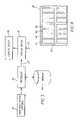
- the systemincludes an input device 20 , processor 22 , memory 24 , display driver 26 and display device 28 .
- the input device 20may include any traditional input device including a joystick, trackball, mouse, rotating dial, switch, button or graphic user interface that may be used to select among two or more options from a series of user options.
- the processor 22is any, or a combination of any, digital or analog, general-purpose or custom controller(s) capable of performing the logic and calculation steps necessary to perform the steps of this invention.
- the processor 22may be any computing device suitable to an application and may, or may not, be combined into a single component with the display driver 26 .
- the memory 24ideally includes non-volatile, writable memory that can be used to store user selections including EPROMS, EEPROMS, memory cards, or magnetic or optical discs.
- the display driver 26is one or more analog or digital signal processors or controllers capable of receiving a standard three-or-more color image signal and converting this signal to a power-saving or lifetime-preserving drive signal compatible with the display device of the present invention. In the case of a display having more than three conventional colors, for example red, green, blue and white, the display driver 26 may also convert a traditional three-color signal to a four-color signal.
- This display driveris additionally capable of receiving a control signal 25 from the processor 22 or a control signal 27 from an external source (not shown) and adjusting the conversion process in response to this control signal. Either or both control signals 25 or 27 may be employed.
- the processor 22may supply the control signal 25 in response to information regarding the age of the display, the charge of the power source, the content of the information to be displayed on the display 28 , or the ambient illumination. Alternatively these signals may be supplied through an external control signal 27 from an ambient illumination sensor (for example a photosensor) or a device for measuring or recording the age of the display, or the charge of a power source.
- an ambient illumination sensorfor example a photosensor
- the display device 28is an OLED display device having an array of pixels, each pixel having OLEDs for providing three or more primary colors that define the gamut of the display device, wherein one of the OLEDs is more efficient than at least one of the other OLEDs.
- the OLEDmay include one or more additional OLEDs emitting a color that is inside the gamut of the display device, preferably having a higher power efficiency than the OLEDs that describe the gamut of the display device.
- An appropriate OLED display devicehas been discussed in a co-pending application, U.S. Ser. No. 10/320,195 filed Dec. 16, 2002 by Miller, et al., which is incorporated herein by reference. A display device with such a pixel arrangement is shown in FIG. 4 .
- FIG. 4shows a display device 28 , that is composed of a number of pixels 42 .
- Each pixel 42 in this display device 28is composed of four OLEDs.
- Three OLEDs that emit red 44 , green 46 , and blue 48 lightdefine the gamut of the display device.
- An additional OLED 50emits light that is substantially white in color and has a chromaticity coordinate that is inside the gamut defined by the chromaticity coordinates of the red 44 , green 46 and blue 48 OLEDs.
- FIG. 5is a standard CIE chromaticity diagram showing a color gamut 52 formed by the chromaticity coordinates of the red, green and blue (R,G,B) OLEDs and the chromaticity coordinate of a white (W) OLED that is inside the gamut 52 .
- a three-color OLED(for example red, green, and blue) having one color, for example green, that is more efficient than the red or blue color light emitters, may reduce the color-differential aging of an OLED display by providing a desaturated color gamut as follows.
- an OLED display driven at 10 volts and 20 mA/cm 2 (200 mW)produces a light output from the green light emitter of 120 cd/m 2 , a light output from the red light emitter of 60 cd/m 2 , and a light output from the blue light emitter of 40 cd/m 2 ;
- the displaycan produce 360 cd/m 2 using 1.2 W to emit a white light at a white point requiring an equal brightness contributions from every emitter.
- a normalized device size of 1 cm 2is used.
- a green color of equivalent brightnesswould require 0.6 W
- a red color of equivalent brightnesswould require 1.2 W
- a blue color of equivalent brightnesswould require 1.8 W.
- this displaywould require between 0.6 W and 1.8 W to emit 360 cd/m 2 .
- the current density of the red light emitterswill be twice that of the green light emitters, and the current density of the blue light emitters will be three times that of the green light emitters.
- the overall power usagemay remain the same but the maximum current density is reduced. For example, if the color gamut is reduced so that half of the light is white and all three color emitters are employed for all emitted colors, a desaturated color gamut green light would require 0.9 W instead of 0.6 W (an increase), a desaturated color gamut red would still require 1.2 W (no change), and a desaturated color gamut blue would require 1.5 W instead of 1.8 W (a decrease). This may, or may not result in an overall decrease in power usage depending on the content displayed on the display.
- the maximum current density in any emitterhas been reduced.
- greenwas at 60 mA, red at 120 mA, and blue at 180 mA to produce saturated colors at 360 cd/m 2 .
- to produce colors at 360 cd/m 2required 90 mA for green, 120 mA for red, and 150 mA for blue.
- the reduced current for the saturated colorsis made up by an increase in the other colors.
- the range of currents in the saturated gamut exampleis from 60 mA to 180 mA while the range of currents in the desaturated example is from 90 mA to 150 mA, a significant reduction in current density differences, thereby reducing differential color aging and preserving display lifetime.
- a three-color OLEDmay employ an additional in-gamut emitter, for example a relatively more efficient white emitter.
- Such an OLEDmay save power by providing a desaturated color-gamut as follows. For example, assume an OLED display driven at 10 volts and 20 mA (200 mW) produces a light output from the white light emitter of 180 cd/m 2 , a light output from the green light emitter of 120 cd/m 2 , a light output from the red light emitter of 60 cd/m 2 , and a light output from the blue light emitter of 40 cd/m 2 .
- the color whitecan be produced by using the white emitter alone without any contribution from the color emitters.
- the color whitecan be produced from a combination of the color emitters without any contribution from the white emitter.
- a color-gamut saturated green color of 360 cd/m 2may be produced using 0.6 W
- a color-gamut saturated red color of 360 cd/m 2may be produced using 1.2 W
- a color-gamut saturated blue color of 360 cd/m 2may be produced using 1.8 W.
- a color-gamut desaturated green colormay be produced by using the white light emitter to produce half the light, as in the first example.
- the power required to produce the color-gamut desaturated green lightis 0.5 W; the power required to produce the color-gamut desaturated red light is 0.8 W; the power required to produce the color-gamut desaturated blue light is 1.1 W.
- the present inventionas applied to the four-color OLED pixel will provide both reduced power consumption and reduced differential color aging.
- a three-color OLEDmay also employ an additional OLED emitter which emits light outside of the gamut defined by the first three colors, for example a more efficient yellow or cyan emitter (relative to the first three colors).
- additional gamut-expanding emittersare described, e.g., in U.S. Pat. 6,570,584.
- Such an OLEDmay save power by providing a desaturated color-gamut by employing the additional emitter to provide light more efficiently than with the red, green, or blue emitters.
- the additional OLED emitterwill expand the overall color gamut, by using the additional emitter in place of at least one of the other colors, the color gamut may be desaturated in accordance with the invention.
- an efficient yellowcan be used to replace green or red, thereby desaturating the green or red color gamut.
- an in-gamut emitterthere are an indefinite number of ways to produce a white color by combining the color elements with the additional emitter.
- the color whitemay be produced by using a yellow emitter in combination with blue and green emitters, or in combination with blue and red emitters, depending upon the white point of the display.
- the color whitemay be produced from a combination of the red, green and blue emitters without any contribution from the additional emitter.
- the present inventiondescribes a way to reduce power usage and improve lifetime for a display by employing a desaturated color gamut.
- a desaturated color gamut in a displaymay reduce the perceived image quality of a display.
- the applicantshave demonstrated through tests that the loss in perceived image quality of a desaturated color gamut display under high ambient light conditions is minimal and much less than the perceived image quality loss of the display under low ambient light conditions.
- the present inventionmay be applied to provide reduced power under bright ambient conditions without compromising either display brightness or perceived image quality.
- control signalmay be produced by a signal representing the ambient illumination.
- the display driver 26 or processor 22may respond to a signal representing the level of light in the ambient illumination.
- the color-gamut saturation of the displayis reduced.
- the color-gamut saturation of the displayis maintained at the maximum color-gamut saturation.
- the transition from color-gamut saturation to desaturationis accomplished gradually as the ambient light illumination increases so that any changes are imperceptible to a viewer. It is possible to limit the color-gamut desaturation to some maximum value to avoid causing a display to become completely monochrome under very bright conditions.
- a minimum valuemay be employed. It is also possible to provide a function, for example a linear or exponential function relating the color-gamut saturation and the ambient illumination to determine the color-gamut saturation desired at a particular ambient illumination level. Such functions may have limits, or damping constants, to limit the rate of change of the color-gamut saturation to reduce the perceptibility of any color-gamut saturation changes.
- the state of the power supplymay dictate the color-gamut saturation.
- aggressive power saving measuresmay be employed to reduce power usage.
- the color gamutmay be desaturated.
- the color gamutmay be saturated.
- a gradual decrease in color-gamut saturationmay be employed to avoid perceptible changes over time.
- the information shown on a displaymay dictate the color-gamut saturation.
- saturated colorsmay not be necessary to communicate information to a user.
- the color gamutmay be desaturated. If images are shown on a display, the use of a fully-saturated color gamut may be preferable.
- powermay be saved when employing a graphic interface.
- graphic interfacestend to use graphic elements for long times at specific locations, possibly causing the light-emissive materials at those display locations to degrade more rapidly than in other locations.
- the present inventionmay be employed to reduce both the current and the range of current densities in those locations. Therefore, the rate of degradation of the emissive materials and color differential degradation may be reduced. This will reduce the effect of image persistence or burn-in for a display.
- the age of the displayit is possible to use the age of the display to dictate the color-gamut saturation.
- Typical OLED materials in use todaydegrade most rapidly when they are first used. After some period of time, the rate of degradation is reduced. In this situation, it may be helpful to reduce color differential aging at the beginning of the display lifetime by employing the present invention. After some period of time, the level of color-gamut desaturation may be reduced. As before, a gradual change in color-gamut saturation may be employed to avoid perceptible changes over time.
- a display userIn is also possible to allow a display user to directly control the color-gamut saturation through a user interface. More likely, a power control mechanism may be employed by the user and the present invention may be employed along with other power saving measures such as display brightness, to reduce power usage or improve display lifetime at the user's discretion. The user can then make tradeoffs between system attributes such as power usage, display visibility, and image quality.
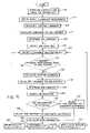
- FIG. 6shows a process that may be employed to practice this invention.
- a control signal that corresponds to a given level of color gamut desaturationis input 60 .
- an appropriate color gamut desaturation value(ranging from zero to one, with one corresponding to a monochrome image and zero indicating no change) is determined 62 .
- the three-color input signalis then converted 64 to linear intensity wherein the linear intensity of a primary is herein defined as a value proportional to the luminance of that primary and scaled such that the combination of unit intensity of each of the three primaries produces a color stimulus having XYZ tristimulus values equal to those of the display white point. Additionally, the proportion of the luminance of each of the three channels used to create white are obtained 66 .
- a matrix to convert from one level of saturation to anotheris determined by multiplying 68 the color gamut desaturation value by the proportions that were obtained in step 66 and adding 70 the resulting values to 1 minus the color gamut desaturation value.
- the desaturated linear intensity valuesare then determined by multiplying 72 the matrix by the linear intensity values.
- the resulting desaturated linear intensity valuesmay then be supplied to the three-to-four color conversion process as described by Murdoch et al. or converted to drive values for a typical three-color display.
- this conversion processmay be further modified to not only reduce power but to help maintain display lifetime.
- OLED luminance stabilitywhen defined as the number of hours required for an OLED to reach half of its initial luminance, is highly dependent upon the drive current. Therefore, if it is determined that the display must perform for a minimum number of hours, e.g., 500, one can use a graph such as FIG. 2 to determine the maximum current density that the OLED can be driven to meet this criteria. Using this criteria, one can see that the blue light emitting OLED can only be driven at a current density of 20 mA/sq. cm while the green and red light emitting OLEDs can be driven at current densities around 35 and 80 mA/sq.
- White emitting materialsare known that perform very well using this criteria and can be driven at or even well beyond 80 mA/sq. cm using this criteria.
- Using this value and a mathematical relationship relating current density to luminance of a display deviceone can determine the maximum luminance and the corresponding maximum linear intensity value that can be achieved for any color light emitting OLED that will not exceed the maximum current density for the appropriate OLED. Therefore, the maximum intensity may be limited and any additional light may be transferred to the neutral channel to be provided by the white-light emitting OLED. In this way, the color-gamut saturation may be reduced for that one color. It should be noted that it is possible that the luminance required from the white-light emitting OLED may also reach a maximum value in which case this luminance may be redistributed to the color light emitting OLEDs using a similar approach.
- the useris able to modify the power usage of the display for a given display brightness by allocating the amount of luminance to be generated by the display away from less power efficient OLEDs and towards more power efficient OLEDs. Therefore, this invention allows the user to trade power efficiency for color gamut saturation.
- the tradeoff of power efficiency for color-gamut saturationmay be made intentionally by the user.
- a menu of possible alternativesmay be displayed to the user as shown in FIG. 7 .
- the alternativescan include, for example, “maximum readability” 54 reducing the white mixing ratio, or “maximum power efficiency” 56 allowing the maximum use of the white OLEDs.
- a “slider”can be provided in the graphic user interface to allow the user to select a continuous level of trade off between image quality and power usage.
- the same tradeoffmay be initiated by other events.
- the user interfacemay provide a control, such as a brightness control for the display.
- a systemmay be able to detect the power level of a battery, such that the display draws less power when the available battery power level reaches some threshold.
- the same tradeoffmay further be made when the system detects lack of user interest or responsiveness. For example when a certain amount of time passes without user interaction, the system may begin to enter a power saving mode.
- the display system of the present inventionmay employ an automatic method for determining ambient illumination, adjusting the brightness of the display in response, and adjusting the color gamut saturation in response to the ambient illumination in a way that makes the loss of saturation appear at a slow enough rate that the change is not readily apparent to the user, while at the same time improving the power efficiency of the display device and/or improving the lifetime of the display under high display luminance conditions.
- the display systemincludes a processor 22 , memory 24 , display driver 26 and a display device 28 .
- the systemalso includes a user input device 20 , which is used to adjust a gain value for the display brightness as described below.
- the systemmay include an ambient illumination sensor 112 such as a photodiode or other sensor that is used to measure the amount of ambient illuminance in the environment that falls on or near the display.
- the systemmay also include other sensors, such as an optional temperature sensor 114 or current sensor 116 .
- the temperature sensor 114may be placed on the back of the display and is used to measure the temperature of the display device. Temperature is another input that could be used to signal the need for reduced color gamut to reduce power consumption and extend the life of the OLED. It is known that the life of an OLED is reduced at higher temperatures and therefore reducing color gamut could offset the reduced OLED life at higher temperatures. OLEDs also tend to consume more power at higher temperatures, further increasing the value of using temperature as an input and reducing color gamut and display luminance as the temperature of the OLED increases.
- the current sensor 116may be used to measure the current being drawn by the display device.
- FIG. 9A method which may be used to adjust the color gamut saturation within this system is shown in FIG. 9 .
- on power up, aim contrast, gain values and additional parametersare obtained 118 .
- An initial ambient illuminanceis then measured 120 using the ambient illumination sensor 112 .
- the luminance required to obtain the aim display contrastis calculated 124 . This calculation is performed to account for the fact that the ambient illuminance is reflected from the display, affecting the luminance of the background and foreground luminance. This value is calculated from the equation:
- L ccL b + ( c - 1 ) ⁇ ( IR ⁇ ) ( 5 )
- L cthe luminance required to achieve the desired contrast
- cthe desired contrast ratio of the white to the black luminance (typically a value greater than 3)
- L bthe minimum emitted display luminance (typically 0 for an OLED display device)
- Ithe ambient illuminance
- Rthe reflectance of the display
- ⁇is the constant pi.
- the initial aim luminanceis determined 126 by taking the maximum of the adapting luminance, the luminance required to obtain the aim display contrast and any minimum luminance constraint that may exist in the parameter set obtained 118 earlier.
- the gain valuewhich is typically a value between 0.5 and 2.0, is then used to adjust 128 the initial aim luminance value through multiplication.
- New ambient illuminance and gain valuesare obtained 130 by obtaining an ambient illuminance measurement from the ambient illumination sensor 112 and by determining any change in the gain value from any change in the state of the user input device 20 . These new values are compared 132 to the initial values. If no change has taken place, new readings of ambient illuminance and gain are obtained 130 and compared 132 again. If a change in ambient illuminance or gain occurs, the adapting luminance is calculated 134 using the new ambient illuminance value and the same equations used to calculate 122 the initial adapting luminance. A new luminance needed to obtain the necessary contrast is calculated 136 using the same equations as described for step 124 . A new aim luminance is determined 138 using the same calculation described for step 126 . Finally this value is adjusted 140 by the new gain value as described for step 128 .
- a step 142is then performed to determine if the aim luminance has increased or decreased. If the aim luminance has decreased, a time constant is selected 144 that is appropriate for dark adaptation, otherwise a time constant is selected 146 that is appropriate for light adaptation. It should be noted that since human light adaptation occurs much more quickly than dark adaptation, the time constant for light adaptation is typically higher than for dark adaptation.
- the new luminanceis then calculated 148 and stored as the new initial luminance.
- This calculation 148is performed by adding a proportion of the change in luminance to the current luminance using an equation of the form:
- LL i + La - Li t ( 6 )
- Lis the new luminance
- L iis the initial luminance
- L ais the adjusted aim luminance calculated 140 earlier
- tis the time constant selected in step 144 or 146 above.
- a formula or look-up table for determining color gamut desaturation as a function of display luminance valuesare then obtained 150, the color gamut desaturation value corresponding the aim luminance value is determined 152 and applied 154 within the conversion process.
- the color gamut desaturation valuescan be changed gradually as the luminance of the display is adapted to the viewing environment. Since the occurrence of dramatic changes in ambient illumination are rare and the rate at which the brightness of the display is changed is slowed by the time constants that are employed, it is unlikely that the individual changes in color gamut saturation will be large using this process. Therefore, while the display will gain and lose color gamut saturation, especially when moved between very low ambient illuminance and very high ambient illuminance environments, it is unlikely that the user will see this change. However, since the color gamut desaturation value will generally be increased with increases in display luminance, the power efficiency and lifetime of the OLEDs that compose the display will be improved.
- the present inventionmay be employed in OLED display having different materials to emit different colors of light.
- the present inventionmay be employed with OLED displays having a single emitter for emitting a broadband light (for example, white) and color filters to produce the different colors of light.
- a broadband lightfor example, white
- the present inventionwill only provide improved power savings in a display device employing only three gamut defining OLEDs if the color filters are differentially efficient but may, in any case, be employed to reduce color differential aging in a display.
- the present inventioncan be employed in most top-or bottom-emitting OLED device configurations. These include simple structures comprising a separate anode and cathode per OLED and more complex structures, such as passive matrix displays having orthogonal arrays of anodes and cathodes to form pixels, and active matrix displays where each pixel is controlled independently, for example, with a thin film transistor (TFT).
- OLED devices and light emitting layersinclude multiple organic layers, including hole and electron transporting and injecting layers, and emissive layers. Such configurations are included within this invention.
- the inventionis employed in a device that includes Organic Light Emitting Diodes (OLEDs) which are composed of small molecule or polymeric OLEDs as disclosed in but not limited to U.S. Pat. No. 4,769,292, issued Sep. 6, 1988 to Tang et al. and U.S. Pat. No. 5,061,569, issued Oct. 29, 1991 to VanSlyke et. al. Many combinations and variations of organic light emitting displays can be used to fabricate such a device.
- OLEDsOrganic Light Emitting Diodes
Landscapes
- Engineering & Computer Science (AREA)
- Physics & Mathematics (AREA)
- Computer Hardware Design (AREA)
- General Physics & Mathematics (AREA)
- Theoretical Computer Science (AREA)
- Electroluminescent Light Sources (AREA)
Abstract
Description
La=10(a+b log(I)) (4)
Where Lais the adapting luminance, I is the ambient illuminance value and a and b are constants that are fit to psychophysical data.
where Lcrepresents the luminance required to achieve the desired contrast, c represents the desired contrast ratio of the white to the black luminance (typically a value greater than 3), Lbrepresents the minimum emitted display luminance (typically 0 for an OLED display device), I is the ambient illuminance, R is the reflectance of the display, and π is the constant pi.
where L is the new luminance, Liis the initial luminance, Lais the adjusted aim luminance calculated140 earlier, and t is the time constant selected in
- 2 luminance transfer function for red OLED
- 4 luminance transfer function for green OLED
- 6 luminance transfer function for blue OLED
- 8 stability curve for red OLED
- 10 stability curve for green OLED
- 12 stability curve for blue OLED
- 20 input device
- 22 processor
- 24 memory
- 25 signal
- 26 display driver
- 27 signal
- 28 display device
- 42 pixel
- 44 red OLED
- 46 green OLED
- 48 blue OLED
- 50 white OLED
- 52 color gamut
- 54 maximum colorfulness selection
- 56 maximum power efficiency selection
- 60 input control signal step
- 62 determine value step
- 64 convert three-color step
- 66 obtain proportion step
- 68 Multiply step
- 70 add step
- 72 multiply step
- 112 ambient illumination sensor
- 114 temperature sensor
- 116 current sensor
- 118 obtain parameters step
- 120 measure ambient illuminance step
- 122 calculate adapting illuminance step
- 124 calculate luminance step
- 126 determine aim luminance step
- 128 adjust gain value step
- 130 obtain new values step
- 132 compare new values step
- 134 calculate adapting luminance step
- 136 calculate new luminance step
- 138 determine new aim luminance step
- 140 adjust luminance value step
- 142 determine increase or decrease step
- 144 select dark adaptation time constant step
- 146 select light adaptation time constant step
- 148 calculate new luminance step
- 150 obtain data for color-gamut saturation step
- 152 determine color-gamut saturation step
- 154 apply color-gamut saturation step
Claims (24)
Priority Applications (1)
| Application Number | Priority Date | Filing Date | Title |
|---|---|---|---|
| US10/812,629US7397485B2 (en) | 2002-12-16 | 2004-03-29 | Color OLED display system having improved performance |
Applications Claiming Priority (3)
| Application Number | Priority Date | Filing Date | Title |
|---|---|---|---|
| US10/320,195US7230594B2 (en) | 2002-12-16 | 2002-12-16 | Color OLED display with improved power efficiency |
| US10/387,953US7184067B2 (en) | 2003-03-13 | 2003-03-13 | Color OLED display system |
| US10/812,629US7397485B2 (en) | 2002-12-16 | 2004-03-29 | Color OLED display system having improved performance |
Related Parent Applications (2)
| Application Number | Title | Priority Date | Filing Date |
|---|---|---|---|
| US10/320,195Continuation-In-PartUS7230594B2 (en) | 2002-12-16 | 2002-12-16 | Color OLED display with improved power efficiency |
| US10/387,953Continuation-In-PartUS7184067B2 (en) | 2002-12-16 | 2003-03-13 | Color OLED display system |
Publications (2)
| Publication Number | Publication Date |
|---|---|
| US20040178974A1 US20040178974A1 (en) | 2004-09-16 |
| US7397485B2true US7397485B2 (en) | 2008-07-08 |
Family
ID=32965288
Family Applications (1)
| Application Number | Title | Priority Date | Filing Date |
|---|---|---|---|
| US10/812,629Expired - LifetimeUS7397485B2 (en) | 2002-12-16 | 2004-03-29 | Color OLED display system having improved performance |
Country Status (1)
| Country | Link |
|---|---|
| US (1) | US7397485B2 (en) |
Cited By (53)
| Publication number | Priority date | Publication date | Assignee | Title |
|---|---|---|---|---|
| US20060055335A1 (en)* | 2004-08-04 | 2006-03-16 | Akira Shingai | Organic-electroluminescence display and driving method therefor |
| US20090278774A1 (en)* | 2008-05-06 | 2009-11-12 | Shing-Chia Chen | Content-adaptive adjustment system and method |
| WO2010085505A1 (en) | 2009-01-21 | 2010-07-29 | Dolby Laboratories Licensing Corporation | Apparatus and methods for color displays |
| US20100225673A1 (en)* | 2009-03-04 | 2010-09-09 | Miller Michael E | Four-channel display power reduction with desaturation |
| US20110043553A1 (en)* | 2009-08-24 | 2011-02-24 | Samsung Electronics Co., Ltd. | Gamut mapping which takes into account pixels in adjacent areas of a display unit |
| US20110050695A1 (en)* | 2009-09-01 | 2011-03-03 | Entertainment Experience Llc | Method for producing a color image and imaging device employing same |
| US20110205397A1 (en)* | 2010-02-24 | 2011-08-25 | John Christopher Hahn | Portable imaging device having display with improved visibility under adverse conditions |
| US20140050393A1 (en)* | 2012-08-17 | 2014-02-20 | Tandent Vision Science, Inc. | Method for performing a multi-clustering merge for use in an image process |
| US8860751B2 (en) | 2009-09-01 | 2014-10-14 | Entertainment Experience Llc | Method for producing a color image and imaging device employing same |
| US20150049899A1 (en)* | 2010-04-08 | 2015-02-19 | Nokia Corporation | Apparatus And Method For Sound Reproduction |
| WO2015083137A1 (en)* | 2013-12-06 | 2015-06-11 | Ignis Innovation Inc. | Oled display system and method |
| US9123668B2 (en) | 2013-10-02 | 2015-09-01 | Apple Inc. | Organic light-emitting diode displays with white subpixels |
| US9355584B2 (en) | 2011-05-20 | 2016-05-31 | Ignis Innovation Inc. | System and methods for extraction of threshold and mobility parameters in AMOLED displays |
| US9418587B2 (en) | 2009-06-16 | 2016-08-16 | Ignis Innovation Inc. | Compensation technique for color shift in displays |
| US9466240B2 (en) | 2011-05-26 | 2016-10-11 | Ignis Innovation Inc. | Adaptive feedback system for compensating for aging pixel areas with enhanced estimation speed |
| US9530352B2 (en) | 2006-08-15 | 2016-12-27 | Ignis Innovations Inc. | OLED luminance degradation compensation |
| US9536460B2 (en) | 2012-05-23 | 2017-01-03 | Ignis Innovation Inc. | Display systems with compensation for line propagation delay |
| US9536465B2 (en) | 2013-03-14 | 2017-01-03 | Ignis Innovation Inc. | Re-interpolation with edge detection for extracting an aging pattern for AMOLED displays |
| US9721512B2 (en) | 2013-03-15 | 2017-08-01 | Ignis Innovation Inc. | AMOLED displays with multiple readout circuits |
| US9761170B2 (en) | 2013-12-06 | 2017-09-12 | Ignis Innovation Inc. | Correction for localized phenomena in an image array |
| US9792857B2 (en) | 2012-02-03 | 2017-10-17 | Ignis Innovation Inc. | Driving system for active-matrix displays |
| US9842544B2 (en) | 2006-04-19 | 2017-12-12 | Ignis Innovation Inc. | Stable driving scheme for active matrix displays |
| US9852689B2 (en) | 2003-09-23 | 2017-12-26 | Ignis Innovation Inc. | Circuit and method for driving an array of light emitting pixels |
| US9947293B2 (en) | 2015-05-27 | 2018-04-17 | Ignis Innovation Inc. | Systems and methods of reduced memory bandwidth compensation |
| US9970964B2 (en) | 2004-12-15 | 2018-05-15 | Ignis Innovation Inc. | Method and system for programming, calibrating and driving a light emitting device display |
| US9984607B2 (en) | 2011-05-27 | 2018-05-29 | Ignis Innovation Inc. | Systems and methods for aging compensation in AMOLED displays |
| US9997110B2 (en) | 2010-12-02 | 2018-06-12 | Ignis Innovation Inc. | System and methods for thermal compensation in AMOLED displays |
| US10012678B2 (en) | 2004-12-15 | 2018-07-03 | Ignis Innovation Inc. | Method and system for programming, calibrating and/or compensating, and driving an LED display |
| US10013907B2 (en) | 2004-12-15 | 2018-07-03 | Ignis Innovation Inc. | Method and system for programming, calibrating and/or compensating, and driving an LED display |
| US10032399B2 (en) | 2010-02-04 | 2018-07-24 | Ignis Innovation Inc. | System and methods for extracting correlation curves for an organic light emitting device |
| US10055186B2 (en) | 2016-06-01 | 2018-08-21 | Dell Products, Lp | Mitigation of image degradation in displays |
| US10074304B2 (en) | 2015-08-07 | 2018-09-11 | Ignis Innovation Inc. | Systems and methods of pixel calibration based on improved reference values |
| US10181282B2 (en) | 2015-01-23 | 2019-01-15 | Ignis Innovation Inc. | Compensation for color variations in emissive devices |
| US10192479B2 (en) | 2014-04-08 | 2019-01-29 | Ignis Innovation Inc. | Display system using system level resources to calculate compensation parameters for a display module in a portable device |
| US10304390B2 (en) | 2009-11-30 | 2019-05-28 | Ignis Innovation Inc. | System and methods for aging compensation in AMOLED displays |
| US10311780B2 (en) | 2015-05-04 | 2019-06-04 | Ignis Innovation Inc. | Systems and methods of optical feedback |
| US10319307B2 (en) | 2009-06-16 | 2019-06-11 | Ignis Innovation Inc. | Display system with compensation techniques and/or shared level resources |
| US10325537B2 (en) | 2011-05-20 | 2019-06-18 | Ignis Innovation Inc. | System and methods for extraction of threshold and mobility parameters in AMOLED displays |
| US10380944B2 (en) | 2011-11-29 | 2019-08-13 | Ignis Innovation Inc. | Structural and low-frequency non-uniformity compensation |
| US10388221B2 (en) | 2005-06-08 | 2019-08-20 | Ignis Innovation Inc. | Method and system for driving a light emitting device display |
| US10439159B2 (en) | 2013-12-25 | 2019-10-08 | Ignis Innovation Inc. | Electrode contacts |
| US10467017B2 (en) | 2017-05-14 | 2019-11-05 | Microsoft Technology Licensing, Llc | Configuration of primary and secondary displays |
| US10475379B2 (en) | 2011-05-20 | 2019-11-12 | Ignis Innovation Inc. | Charged-based compensation and parameter extraction in AMOLED displays |
| US10483288B2 (en) | 2008-07-10 | 2019-11-19 | Semiconductor Energy Laboratory Co., Ltd. | Light-emitting device and electronic device using the same |
| CN110622622A (en)* | 2017-03-02 | 2019-12-27 | 宾州研究基金会 | Light source for increasing object chromaticity when dimming |
| US10573231B2 (en) | 2010-02-04 | 2020-02-25 | Ignis Innovation Inc. | System and methods for extracting correlation curves for an organic light emitting device |
| US10699613B2 (en) | 2009-11-30 | 2020-06-30 | Ignis Innovation Inc. | Resetting cycle for aging compensation in AMOLED displays |
| US10971043B2 (en) | 2010-02-04 | 2021-04-06 | Ignis Innovation Inc. | System and method for extracting correlation curves for an organic light emitting device |
| US11200839B2 (en) | 2010-02-04 | 2021-12-14 | Ignis Innovation Inc. | System and methods for extracting correlation curves for an organic light emitting device |
| US11594578B2 (en) | 2012-03-06 | 2023-02-28 | Samsung Display Co., Ltd. | Pixel arrangement structure for organic light emitting display device |
| US11626068B2 (en) | 2012-03-06 | 2023-04-11 | Samsung Display Co., Ltd. | Pixel arrangement structure for organic light emitting diode display |
| US11950457B2 (en) | 2018-11-21 | 2024-04-02 | Samsung Display Co., Ltd. | Display device |
| US12022684B2 (en) | 2018-09-14 | 2024-06-25 | 3M Innovative Properties Company | Polarizer and display including same |
Families Citing this family (47)
| Publication number | Priority date | Publication date | Assignee | Title |
|---|---|---|---|---|
| US7184067B2 (en)* | 2003-03-13 | 2007-02-27 | Eastman Kodak Company | Color OLED display system |
| US7075242B2 (en)* | 2002-12-16 | 2006-07-11 | Eastman Kodak Company | Color OLED display system having improved performance |
| US7230594B2 (en)* | 2002-12-16 | 2007-06-12 | Eastman Kodak Company | Color OLED display with improved power efficiency |
| US7333080B2 (en) | 2004-03-29 | 2008-02-19 | Eastman Kodak Company | Color OLED display with improved power efficiency |
| JP2005301095A (en)* | 2004-04-15 | 2005-10-27 | Semiconductor Energy Lab Co Ltd | Display device |
| GB0408486D0 (en)* | 2004-04-16 | 2004-05-19 | Koninkl Philips Electronics Nv | Electroluminescent display device |
| US7595796B2 (en)* | 2004-04-23 | 2009-09-29 | Hewlett-Packard Development Company, L.P. | Optimizing lifetime of a display |
| JP2006003475A (en)* | 2004-06-15 | 2006-01-05 | Eastman Kodak Co | Oled display device |
| JP4274070B2 (en)* | 2004-07-23 | 2009-06-03 | ソニー株式会社 | Display device and driving method thereof |
| ITTO20050028A1 (en)* | 2005-01-21 | 2006-07-22 | Space Cannon Vh Srl | LED DEVICE INCLUDING A PLURALITY OF LED DIODES |
| KR100729060B1 (en)* | 2005-03-31 | 2007-06-14 | 삼성에스디아이 주식회사 | Light-emitting display device and driving method thereof |
| US20070035751A1 (en)* | 2005-08-15 | 2007-02-15 | Microsoft Corporation | Gamut shape dependent color management system |
| US7636076B2 (en)* | 2005-09-22 | 2009-12-22 | Au Optronics Corporation | Four-color transflective color liquid crystal display |
| WO2007047537A2 (en)* | 2005-10-14 | 2007-04-26 | Clairvoyante, Inc. | Improved gamut mapping and subpixel rendering systems and methods |
| JP4899447B2 (en)* | 2005-11-25 | 2012-03-21 | ソニー株式会社 | Self-luminous display device, light emission condition control device, light emission condition control method, and program |
| US7710022B2 (en)* | 2006-01-27 | 2010-05-04 | Global Oled Technology Llc | EL device having improved power distribution |
| KR100763239B1 (en)* | 2006-06-27 | 2007-10-04 | 삼성전자주식회사 | Image processing apparatus and method for improving the visibility of the displayed image |
| US20080012692A1 (en)* | 2006-06-29 | 2008-01-17 | Michael Pyle | Systems and methods for providing spectral feedback to visually convey a quantitative value |
| CN201042115Y (en)* | 2007-04-04 | 2008-03-26 | 富士康(昆山)电脑接插件有限公司 | circuit board lock |
| KR101480001B1 (en)* | 2008-02-26 | 2015-01-09 | 삼성디스플레이 주식회사 | Organic light emminting display device and processing method image signals thereof |
| JP4623138B2 (en) | 2008-05-21 | 2011-02-02 | ソニー株式会社 | Display device and electronic device |
| US8237642B2 (en)* | 2008-07-14 | 2012-08-07 | Global Oled Technology Llc | Method for improving display lifetime |
| TWI423221B (en)* | 2010-10-27 | 2014-01-11 | Au Optronics Corp | Method for driving active matrix organic light emitting diode display panel |
| US9361822B2 (en)* | 2011-11-09 | 2016-06-07 | Apple Inc. | Color adjustment techniques for displays |
| KR101862793B1 (en) | 2012-08-08 | 2018-05-31 | 삼성디스플레이 주식회사 | Pixel Array Structure and Organic Light Emitting Display including The Same |
| US9798698B2 (en) | 2012-08-13 | 2017-10-24 | Nvidia Corporation | System and method for multi-color dilu preconditioner |
| US9508318B2 (en)* | 2012-09-13 | 2016-11-29 | Nvidia Corporation | Dynamic color profile management for electronic devices |
| US20140198084A1 (en)* | 2013-01-16 | 2014-07-17 | Stefan Peana | Method and system for display brightness and color optimization |
| KR102035854B1 (en)* | 2013-02-08 | 2019-10-24 | 삼성디스플레이 주식회사 | Power Saving Method and Power Saving Display Device |
| US9459141B2 (en) | 2014-03-11 | 2016-10-04 | Getac Technology Corporation | Brightness control apparatus and brightness control method |
| DE102014104087A1 (en)* | 2014-03-25 | 2015-10-01 | Getac Technology Corp. | Brightness controller and brightness control method |
| DE102014104769A1 (en)* | 2014-04-03 | 2015-10-08 | Osram Opto Semiconductors Gmbh | Method for controlling a screen display of a screen and electronic device |
| DE102014221057A1 (en)* | 2014-10-16 | 2016-04-21 | Continental Automotive Gmbh | Method for operating a display device, arrangement and motor vehicle |
| CN104269138B (en)* | 2014-10-24 | 2017-04-05 | 京东方科技集团股份有限公司 | White light OLED display device and its display control method, display control unit |
| KR102325675B1 (en)* | 2014-12-29 | 2021-11-12 | 삼성디스플레이 주식회사 | Organic Light Emitting Display Device |
| CA2973186C (en)* | 2015-01-13 | 2021-12-21 | Magic Leap, Inc. | Improved color sequential display |
| KR102658426B1 (en)* | 2016-05-31 | 2024-04-17 | 엘지디스플레이 주식회사 | Organic Light Emitting Display And Driving Method Thereof |
| US20180098041A1 (en)* | 2016-09-30 | 2018-04-05 | Sean J. Lawrence | Adaptive chroma subsampling based on display brightness |
| CN106782370B (en)* | 2016-12-20 | 2018-05-11 | 武汉华星光电技术有限公司 | The driving method and driving device of a kind of display panel |
| JP2018155714A (en)* | 2017-03-21 | 2018-10-04 | アズビル株式会社 | Field device and deterioration diagnosis method |
| KR102527793B1 (en)* | 2017-10-16 | 2023-05-04 | 삼성디스플레이 주식회사 | Display device and driving method thereof |
| KR102523646B1 (en) | 2017-11-01 | 2023-04-21 | 삼성디스플레이 주식회사 | Display device and driving method thereof |
| CN113228156B (en)* | 2018-10-17 | 2024-08-09 | 康宁股份有限公司 | Method for realizing reduced energy consumption of display device and device with reduced energy consumption of display device |
| WO2020100200A1 (en)* | 2018-11-12 | 2020-05-22 | Eizo株式会社 | Image processing system, image processing device, and computer program |
| JP7669133B2 (en)* | 2019-11-29 | 2025-04-28 | キヤノン株式会社 | Display devices and equipment |
| EP4050384A4 (en)* | 2019-11-29 | 2023-12-27 | Canon Kabushiki Kaisha | DISPLAY DEVICE AND DEVICE |
| WO2024245767A1 (en)* | 2023-05-26 | 2024-12-05 | Interdigital Ce Patent Holdings, Sas | Method and device for adjustable energy reduction control of visual content using alternating complementary colors |
Citations (29)
| Publication number | Priority date | Publication date | Assignee | Title |
|---|---|---|---|---|
| US3813686A (en) | 1972-11-27 | 1974-05-28 | Magnovox Co | Ambient light responsive control of brightness, contrast and color saturation |
| US4800375A (en) | 1986-10-24 | 1989-01-24 | Honeywell Inc. | Four color repetitive sequence matrix array for flat panel displays |
| US5233385A (en) | 1991-12-18 | 1993-08-03 | Texas Instruments Incorporated | White light enhanced color field sequential projection |
| US5526016A (en) | 1991-06-28 | 1996-06-11 | Citizen Watch Co., Ltd. | Multicolor display apparatus |
| US5563621A (en) | 1991-11-18 | 1996-10-08 | Black Box Vision Limited | Display apparatus |
| US5638084A (en) | 1992-05-22 | 1997-06-10 | Dielectric Systems International, Inc. | Lighting-independent color video display |
| JPH10254386A (en) | 1997-03-14 | 1998-09-25 | Sony Corp | Color image display |
| WO2000011728A1 (en) | 1998-08-19 | 2000-03-02 | Cambridge Display Technology Ltd. | Display devices |
| US6075514A (en) | 1998-02-05 | 2000-06-13 | Canon Kabushiki Kaisha | Color table look-up having last value memory |
| JP2000200061A (en) | 1999-01-05 | 2000-07-18 | Nec Corp | Display device and control method thereof |
| US6133692A (en) | 1998-06-08 | 2000-10-17 | Motorola, Inc. | White light generating organic electroluminescent device and method of fabrication |
| WO2000070400A1 (en) | 1999-05-17 | 2000-11-23 | Reveo, Inc. | High-brightness color liquid crystal display panel employing light recycling therewithin |
| US6262710B1 (en) | 1999-05-25 | 2001-07-17 | Intel Corporation | Performing color conversion in extended color polymer displays |
| WO2001099195A1 (en) | 2000-06-23 | 2001-12-27 | Cambridge Display Technology Limited | Light-emitting devices |
| US20020015110A1 (en) | 2000-07-28 | 2002-02-07 | Clairvoyante Laboratories, Inc. | Arrangement of color pixels for full color imaging devices with simplified addressing |
| US20020024618A1 (en) | 2000-08-31 | 2002-02-28 | Nec Corporation | Field sequential display of color video picture with color breakup prevention |
| US6388644B1 (en) | 1999-02-24 | 2002-05-14 | U.S. Philips Corporation | Color display device |
| US6411306B1 (en) | 1997-11-14 | 2002-06-25 | Eastman Kodak Company | Automatic luminance and contrast adustment for display device |
| US6483245B1 (en) | 2000-09-08 | 2002-11-19 | Visteon Corporation | Automatic brightness control using a variable time constant filter |
| US20020186214A1 (en) | 2001-06-05 | 2002-12-12 | Eastman Kodak Company | Method for saving power in an organic electroluminescent display using white light emitting elements |
| US6498592B1 (en) | 1999-02-16 | 2002-12-24 | Sarnoff Corp. | Display tile structure using organic light emitting materials |
| US20020196208A1 (en) | 2000-10-27 | 2002-12-26 | Yutaka Nanno | Display |
| US20030103058A1 (en) | 2001-05-09 | 2003-06-05 | Candice Hellen Brown Elliott | Methods and systems for sub-pixel rendering with gamma adjustment |
| US20040051724A1 (en) | 2002-09-13 | 2004-03-18 | Elliott Candice Hellen Brown | Four color arrangements of emitters for subpixel rendering |
| US20040113875A1 (en) | 2002-12-16 | 2004-06-17 | Eastman Kodak Company | Color oled display with improved power efficiency |
| US20040178743A1 (en) | 2002-12-16 | 2004-09-16 | Eastman Kodak Company | Color OLED display system having improved performance |
| US20040178973A1 (en) | 2003-03-13 | 2004-09-16 | Eastman Kodak Company | Color OLED display system |
| US20040195963A1 (en) | 2003-04-07 | 2004-10-07 | Samsung Electronics Co., Ltd. | Organic electro-luminescent display device |
| US20040222999A1 (en) | 2003-05-07 | 2004-11-11 | Beohm-Rock Choi | Four-color data processing system |
Family Cites Families (1)
| Publication number | Priority date | Publication date | Assignee | Title |
|---|---|---|---|---|
| US6498952B2 (en)* | 2001-03-08 | 2002-12-24 | Pacesetter, Inc. | Hermetically sealed feedthrough connector using shape memory alloy for implantable medical device |
- 2004
- 2004-03-29USUS10/812,629patent/US7397485B2/ennot_activeExpired - Lifetime
Patent Citations (30)
| Publication number | Priority date | Publication date | Assignee | Title |
|---|---|---|---|---|
| US3813686A (en) | 1972-11-27 | 1974-05-28 | Magnovox Co | Ambient light responsive control of brightness, contrast and color saturation |
| US4800375A (en) | 1986-10-24 | 1989-01-24 | Honeywell Inc. | Four color repetitive sequence matrix array for flat panel displays |
| US5526016A (en) | 1991-06-28 | 1996-06-11 | Citizen Watch Co., Ltd. | Multicolor display apparatus |
| US5563621A (en) | 1991-11-18 | 1996-10-08 | Black Box Vision Limited | Display apparatus |
| EP0830032A2 (en) | 1991-12-18 | 1998-03-18 | Texas Instruments Incorporated | White light enhanced colour field sequential projection system |
| US5233385A (en) | 1991-12-18 | 1993-08-03 | Texas Instruments Incorporated | White light enhanced color field sequential projection |
| US5638084A (en) | 1992-05-22 | 1997-06-10 | Dielectric Systems International, Inc. | Lighting-independent color video display |
| JPH10254386A (en) | 1997-03-14 | 1998-09-25 | Sony Corp | Color image display |
| US6411306B1 (en) | 1997-11-14 | 2002-06-25 | Eastman Kodak Company | Automatic luminance and contrast adustment for display device |
| US6075514A (en) | 1998-02-05 | 2000-06-13 | Canon Kabushiki Kaisha | Color table look-up having last value memory |
| US6133692A (en) | 1998-06-08 | 2000-10-17 | Motorola, Inc. | White light generating organic electroluminescent device and method of fabrication |
| WO2000011728A1 (en) | 1998-08-19 | 2000-03-02 | Cambridge Display Technology Ltd. | Display devices |
| JP2000200061A (en) | 1999-01-05 | 2000-07-18 | Nec Corp | Display device and control method thereof |
| US6498592B1 (en) | 1999-02-16 | 2002-12-24 | Sarnoff Corp. | Display tile structure using organic light emitting materials |
| US6388644B1 (en) | 1999-02-24 | 2002-05-14 | U.S. Philips Corporation | Color display device |
| WO2000070400A1 (en) | 1999-05-17 | 2000-11-23 | Reveo, Inc. | High-brightness color liquid crystal display panel employing light recycling therewithin |
| US6262710B1 (en) | 1999-05-25 | 2001-07-17 | Intel Corporation | Performing color conversion in extended color polymer displays |
| WO2001099195A1 (en) | 2000-06-23 | 2001-12-27 | Cambridge Display Technology Limited | Light-emitting devices |
| US20020015110A1 (en) | 2000-07-28 | 2002-02-07 | Clairvoyante Laboratories, Inc. | Arrangement of color pixels for full color imaging devices with simplified addressing |
| US20020024618A1 (en) | 2000-08-31 | 2002-02-28 | Nec Corporation | Field sequential display of color video picture with color breakup prevention |
| US6483245B1 (en) | 2000-09-08 | 2002-11-19 | Visteon Corporation | Automatic brightness control using a variable time constant filter |
| US20020196208A1 (en) | 2000-10-27 | 2002-12-26 | Yutaka Nanno | Display |
| US20030103058A1 (en) | 2001-05-09 | 2003-06-05 | Candice Hellen Brown Elliott | Methods and systems for sub-pixel rendering with gamma adjustment |
| US20020186214A1 (en) | 2001-06-05 | 2002-12-12 | Eastman Kodak Company | Method for saving power in an organic electroluminescent display using white light emitting elements |
| US20040051724A1 (en) | 2002-09-13 | 2004-03-18 | Elliott Candice Hellen Brown | Four color arrangements of emitters for subpixel rendering |
| US20040113875A1 (en) | 2002-12-16 | 2004-06-17 | Eastman Kodak Company | Color oled display with improved power efficiency |
| US20040178743A1 (en) | 2002-12-16 | 2004-09-16 | Eastman Kodak Company | Color OLED display system having improved performance |
| US20040178973A1 (en) | 2003-03-13 | 2004-09-16 | Eastman Kodak Company | Color OLED display system |
| US20040195963A1 (en) | 2003-04-07 | 2004-10-07 | Samsung Electronics Co., Ltd. | Organic electro-luminescent display device |
| US20040222999A1 (en) | 2003-05-07 | 2004-11-11 | Beohm-Rock Choi | Four-color data processing system |
Non-Patent Citations (1)
| Title |
|---|
| Klompenhouwer et al.; "Subpixel Image Scaling For Color Matrix Displays"; SID 02 Digest; pp. 176-179. |
Cited By (119)
| Publication number | Priority date | Publication date | Assignee | Title |
|---|---|---|---|---|
| US9852689B2 (en) | 2003-09-23 | 2017-12-26 | Ignis Innovation Inc. | Circuit and method for driving an array of light emitting pixels |
| US20060055335A1 (en)* | 2004-08-04 | 2006-03-16 | Akira Shingai | Organic-electroluminescence display and driving method therefor |
| US10013907B2 (en) | 2004-12-15 | 2018-07-03 | Ignis Innovation Inc. | Method and system for programming, calibrating and/or compensating, and driving an LED display |
| US10012678B2 (en) | 2004-12-15 | 2018-07-03 | Ignis Innovation Inc. | Method and system for programming, calibrating and/or compensating, and driving an LED display |
| US9970964B2 (en) | 2004-12-15 | 2018-05-15 | Ignis Innovation Inc. | Method and system for programming, calibrating and driving a light emitting device display |
| US10699624B2 (en) | 2004-12-15 | 2020-06-30 | Ignis Innovation Inc. | Method and system for programming, calibrating and/or compensating, and driving an LED display |
| US10388221B2 (en) | 2005-06-08 | 2019-08-20 | Ignis Innovation Inc. | Method and system for driving a light emitting device display |
| US10127860B2 (en) | 2006-04-19 | 2018-11-13 | Ignis Innovation Inc. | Stable driving scheme for active matrix displays |
| US9842544B2 (en) | 2006-04-19 | 2017-12-12 | Ignis Innovation Inc. | Stable driving scheme for active matrix displays |
| US10453397B2 (en) | 2006-04-19 | 2019-10-22 | Ignis Innovation Inc. | Stable driving scheme for active matrix displays |
| US10325554B2 (en) | 2006-08-15 | 2019-06-18 | Ignis Innovation Inc. | OLED luminance degradation compensation |
| US9530352B2 (en) | 2006-08-15 | 2016-12-27 | Ignis Innovations Inc. | OLED luminance degradation compensation |
| US20090278774A1 (en)* | 2008-05-06 | 2009-11-12 | Shing-Chia Chen | Content-adaptive adjustment system and method |
| US10916567B2 (en) | 2008-07-10 | 2021-02-09 | Semiconductor Energy Laboratory Co., Ltd. | Light-emitting device and electronic device using the same |
| US12191312B2 (en) | 2008-07-10 | 2025-01-07 | Semiconductor Energy Laboratory Co., Ltd. | Light-emitting device and electronic device using the same |
| US11631702B2 (en) | 2008-07-10 | 2023-04-18 | Semiconductor Energy Laboratory Co., Ltd. | Light-emitting device and electronic device using the same |
| US10529741B2 (en) | 2008-07-10 | 2020-01-07 | Semiconductor Energy Laboratory Co., Ltd. | Light-emitting device and electronic device using the same |
| US10483288B2 (en) | 2008-07-10 | 2019-11-19 | Semiconductor Energy Laboratory Co., Ltd. | Light-emitting device and electronic device using the same |
| US9343042B2 (en)* | 2008-07-14 | 2016-05-17 | Global Oled Technology Llc | Four-channel display with desaturation and luminance gain |
| US9343040B2 (en)* | 2008-07-14 | 2016-05-17 | Global Oled Technology Llc | Four-channel display power reduction with desaturation |
| US9659532B2 (en) | 2008-07-14 | 2017-05-23 | Global Oled Technology Llc | Four-channel transmissive display system |
| US9343041B2 (en)* | 2008-07-14 | 2016-05-17 | Global Oled Technology Llc | Four-channel emissive display system |
| US20150179138A1 (en)* | 2008-07-14 | 2015-06-25 | Global Oled Technology Llc | Four-channel display with desaturation and luminance gain |
| US20150179137A1 (en)* | 2008-07-14 | 2015-06-25 | Global Oled Technology Llc | Four-channel emissive display system |
| US20150179136A1 (en)* | 2008-07-14 | 2015-06-25 | Global Oled Technology Llc | Four-channel display power reduction with desaturation |
| WO2010085505A1 (en) | 2009-01-21 | 2010-07-29 | Dolby Laboratories Licensing Corporation | Apparatus and methods for color displays |
| EP3422337A1 (en) | 2009-01-21 | 2019-01-02 | Guangdong OPPO Mobile Telecommunications Corp., Ltd. | Apparatus and methods for color displays |
| EP3422338A1 (en) | 2009-01-21 | 2019-01-02 | Guangdong OPPO Mobile Telecommunications Corp., Ltd. | Apparatus and methods for color displays |
| EP3422339A1 (en) | 2009-01-21 | 2019-01-02 | Guangdong OPPO Mobile Telecommunications Corp., Ltd. | Apparatus and methods for color displays |
| US8711085B2 (en) | 2009-01-21 | 2014-04-29 | Dolby Laboratories Licensing Corporation | Apparatus and methods for color displays |
| US20100225673A1 (en)* | 2009-03-04 | 2010-09-09 | Miller Michael E | Four-channel display power reduction with desaturation |
| US10319307B2 (en) | 2009-06-16 | 2019-06-11 | Ignis Innovation Inc. | Display system with compensation techniques and/or shared level resources |
| US9418587B2 (en) | 2009-06-16 | 2016-08-16 | Ignis Innovation Inc. | Compensation technique for color shift in displays |
| US10553141B2 (en) | 2009-06-16 | 2020-02-04 | Ignis Innovation Inc. | Compensation technique for color shift in displays |
| US8223180B2 (en)* | 2009-08-24 | 2012-07-17 | Samsung Electronics Co., Ltd. | Gamut mapping which takes into account pixels in adjacent areas of a display unit |
| US20110043553A1 (en)* | 2009-08-24 | 2011-02-24 | Samsung Electronics Co., Ltd. | Gamut mapping which takes into account pixels in adjacent areas of a display unit |
| US20110050695A1 (en)* | 2009-09-01 | 2011-03-03 | Entertainment Experience Llc | Method for producing a color image and imaging device employing same |
| US9997135B2 (en) | 2009-09-01 | 2018-06-12 | Entertainment Experience Llc | Method for producing a color image and imaging device employing same |
| US9529409B2 (en) | 2009-09-01 | 2016-12-27 | Entertainment Experience Llc | Method for producing a color image and imaging device employing same |
| US8767006B2 (en) | 2009-09-01 | 2014-07-01 | Entertainment Experience Llc | Method for producing a color image and imaging device employing same |
| US8860751B2 (en) | 2009-09-01 | 2014-10-14 | Entertainment Experience Llc | Method for producing a color image and imaging device employing same |
| US8520023B2 (en) | 2009-09-01 | 2013-08-27 | Entertainment Experience Llc | Method for producing a color image and imaging device employing same |
| US9418622B2 (en) | 2009-09-01 | 2016-08-16 | Entertainment Experience Llc | Method for producing a color image and imaging device employing same |
| US12033589B2 (en) | 2009-11-30 | 2024-07-09 | Ignis Innovation Inc. | System and methods for aging compensation in AMOLED displays |
| US10699613B2 (en) | 2009-11-30 | 2020-06-30 | Ignis Innovation Inc. | Resetting cycle for aging compensation in AMOLED displays |
| US10304390B2 (en) | 2009-11-30 | 2019-05-28 | Ignis Innovation Inc. | System and methods for aging compensation in AMOLED displays |
| US10395574B2 (en) | 2010-02-04 | 2019-08-27 | Ignis Innovation Inc. | System and methods for extracting correlation curves for an organic light emitting device |
| US10573231B2 (en) | 2010-02-04 | 2020-02-25 | Ignis Innovation Inc. | System and methods for extracting correlation curves for an organic light emitting device |
| US11200839B2 (en) | 2010-02-04 | 2021-12-14 | Ignis Innovation Inc. | System and methods for extracting correlation curves for an organic light emitting device |
| US10032399B2 (en) | 2010-02-04 | 2018-07-24 | Ignis Innovation Inc. | System and methods for extracting correlation curves for an organic light emitting device |
| US10971043B2 (en) | 2010-02-04 | 2021-04-06 | Ignis Innovation Inc. | System and method for extracting correlation curves for an organic light emitting device |
| US20110205397A1 (en)* | 2010-02-24 | 2011-08-25 | John Christopher Hahn | Portable imaging device having display with improved visibility under adverse conditions |
| US20150049899A1 (en)* | 2010-04-08 | 2015-02-19 | Nokia Corporation | Apparatus And Method For Sound Reproduction |
| US9313567B2 (en)* | 2010-04-08 | 2016-04-12 | Nokia Technologies Oy | Apparatus and method for sound reproduction |
| US9997110B2 (en) | 2010-12-02 | 2018-06-12 | Ignis Innovation Inc. | System and methods for thermal compensation in AMOLED displays |
| US10460669B2 (en) | 2010-12-02 | 2019-10-29 | Ignis Innovation Inc. | System and methods for thermal compensation in AMOLED displays |
| US10127846B2 (en) | 2011-05-20 | 2018-11-13 | Ignis Innovation Inc. | System and methods for extraction of threshold and mobility parameters in AMOLED displays |
| US9355584B2 (en) | 2011-05-20 | 2016-05-31 | Ignis Innovation Inc. | System and methods for extraction of threshold and mobility parameters in AMOLED displays |
| US9589490B2 (en) | 2011-05-20 | 2017-03-07 | Ignis Innovation Inc. | System and methods for extraction of threshold and mobility parameters in AMOLED displays |
| US9799248B2 (en) | 2011-05-20 | 2017-10-24 | Ignis Innovation Inc. | System and methods for extraction of threshold and mobility parameters in AMOLED displays |
| US10580337B2 (en) | 2011-05-20 | 2020-03-03 | Ignis Innovation Inc. | System and methods for extraction of threshold and mobility parameters in AMOLED displays |
| US10325537B2 (en) | 2011-05-20 | 2019-06-18 | Ignis Innovation Inc. | System and methods for extraction of threshold and mobility parameters in AMOLED displays |
| US10475379B2 (en) | 2011-05-20 | 2019-11-12 | Ignis Innovation Inc. | Charged-based compensation and parameter extraction in AMOLED displays |
| US9978297B2 (en) | 2011-05-26 | 2018-05-22 | Ignis Innovation Inc. | Adaptive feedback system for compensating for aging pixel areas with enhanced estimation speed |
| US10706754B2 (en) | 2011-05-26 | 2020-07-07 | Ignis Innovation Inc. | Adaptive feedback system for compensating for aging pixel areas with enhanced estimation speed |
| US9640112B2 (en) | 2011-05-26 | 2017-05-02 | Ignis Innovation Inc. | Adaptive feedback system for compensating for aging pixel areas with enhanced estimation speed |
| US9466240B2 (en) | 2011-05-26 | 2016-10-11 | Ignis Innovation Inc. | Adaptive feedback system for compensating for aging pixel areas with enhanced estimation speed |
| US9984607B2 (en) | 2011-05-27 | 2018-05-29 | Ignis Innovation Inc. | Systems and methods for aging compensation in AMOLED displays |
| US10417945B2 (en) | 2011-05-27 | 2019-09-17 | Ignis Innovation Inc. | Systems and methods for aging compensation in AMOLED displays |
| US10380944B2 (en) | 2011-11-29 | 2019-08-13 | Ignis Innovation Inc. | Structural and low-frequency non-uniformity compensation |
| US10453394B2 (en) | 2012-02-03 | 2019-10-22 | Ignis Innovation Inc. | Driving system for active-matrix displays |
| US9792857B2 (en) | 2012-02-03 | 2017-10-17 | Ignis Innovation Inc. | Driving system for active-matrix displays |
| US10043448B2 (en) | 2012-02-03 | 2018-08-07 | Ignis Innovation Inc. | Driving system for active-matrix displays |
| US12183272B2 (en) | 2012-03-06 | 2024-12-31 | Samsung Display Co., Ltd. | Pixel arrangement structure for organic light emitting diode display |
| US11594578B2 (en) | 2012-03-06 | 2023-02-28 | Samsung Display Co., Ltd. | Pixel arrangement structure for organic light emitting display device |
| US11651731B2 (en) | 2012-03-06 | 2023-05-16 | Samsung Display Co., Ltd. | Pixel arrangement structure for organic light emitting diode display |
| US12324335B2 (en) | 2012-03-06 | 2025-06-03 | Samsung Display Co., Ltd. | Pixel arrangement structure for organic light emitting display device |
| US11626067B2 (en) | 2012-03-06 | 2023-04-11 | Samsung Display Co., Ltd. | Pixel arrangement structure for organic light emitting diode display |
| US11626064B2 (en) | 2012-03-06 | 2023-04-11 | Samsung Display Co., Ltd. | Pixel arrangement structure for organic light emitting diode display |
| US11676531B2 (en) | 2012-03-06 | 2023-06-13 | Samsung Display Co., Ltd. | Pixel arrangement structure for organic light emitting diode display |
| US11626068B2 (en) | 2012-03-06 | 2023-04-11 | Samsung Display Co., Ltd. | Pixel arrangement structure for organic light emitting diode display |
| US11980077B2 (en) | 2012-03-06 | 2024-05-07 | Samsung Display Co., Ltd. | Pixel arrangement structure for organic light emitting display device |
| US11626066B2 (en) | 2012-03-06 | 2023-04-11 | Samsung Display Co., Ltd. | Pixel arrangement structure for organic light emitting diode display |
| US12266298B2 (en) | 2012-03-06 | 2025-04-01 | Samsung Display Co., Ltd. | Pixel arrangement structure for organic light emitting diode display |
| US12175927B2 (en) | 2012-03-06 | 2024-12-24 | Samsung Display Co., Ltd. | Pixel arrangement structure for organic light emitting diode display |
| US10176738B2 (en) | 2012-05-23 | 2019-01-08 | Ignis Innovation Inc. | Display systems with compensation for line propagation delay |
| US9536460B2 (en) | 2012-05-23 | 2017-01-03 | Ignis Innovation Inc. | Display systems with compensation for line propagation delay |
| US9741279B2 (en) | 2012-05-23 | 2017-08-22 | Ignis Innovation Inc. | Display systems with compensation for line propagation delay |
| US9940861B2 (en) | 2012-05-23 | 2018-04-10 | Ignis Innovation Inc. | Display systems with compensation for line propagation delay |
| US8842907B2 (en)* | 2012-08-17 | 2014-09-23 | Tandent Vision Science, Inc. | Method for performing a multi-clustering merge for use in an image process |
| US20140050393A1 (en)* | 2012-08-17 | 2014-02-20 | Tandent Vision Science, Inc. | Method for performing a multi-clustering merge for use in an image process |
| US9818323B2 (en) | 2013-03-14 | 2017-11-14 | Ignis Innovation Inc. | Re-interpolation with edge detection for extracting an aging pattern for AMOLED displays |
| US10198979B2 (en) | 2013-03-14 | 2019-02-05 | Ignis Innovation Inc. | Re-interpolation with edge detection for extracting an aging pattern for AMOLED displays |
| US9536465B2 (en) | 2013-03-14 | 2017-01-03 | Ignis Innovation Inc. | Re-interpolation with edge detection for extracting an aging pattern for AMOLED displays |
| US9721512B2 (en) | 2013-03-15 | 2017-08-01 | Ignis Innovation Inc. | AMOLED displays with multiple readout circuits |
| US10460660B2 (en) | 2013-03-15 | 2019-10-29 | Ingis Innovation Inc. | AMOLED displays with multiple readout circuits |
| US9997107B2 (en) | 2013-03-15 | 2018-06-12 | Ignis Innovation Inc. | AMOLED displays with multiple readout circuits |
| US9123668B2 (en) | 2013-10-02 | 2015-09-01 | Apple Inc. | Organic light-emitting diode displays with white subpixels |
| US9761170B2 (en) | 2013-12-06 | 2017-09-12 | Ignis Innovation Inc. | Correction for localized phenomena in an image array |
| US9741282B2 (en) | 2013-12-06 | 2017-08-22 | Ignis Innovation Inc. | OLED display system and method |
| US10395585B2 (en) | 2013-12-06 | 2019-08-27 | Ignis Innovation Inc. | OLED display system and method |
| US10186190B2 (en) | 2013-12-06 | 2019-01-22 | Ignis Innovation Inc. | Correction for localized phenomena in an image array |
| WO2015083137A1 (en)* | 2013-12-06 | 2015-06-11 | Ignis Innovation Inc. | Oled display system and method |
| US10439159B2 (en) | 2013-12-25 | 2019-10-08 | Ignis Innovation Inc. | Electrode contacts |
| US10192479B2 (en) | 2014-04-08 | 2019-01-29 | Ignis Innovation Inc. | Display system using system level resources to calculate compensation parameters for a display module in a portable device |
| US10181282B2 (en) | 2015-01-23 | 2019-01-15 | Ignis Innovation Inc. | Compensation for color variations in emissive devices |
| US10311780B2 (en) | 2015-05-04 | 2019-06-04 | Ignis Innovation Inc. | Systems and methods of optical feedback |
| US9947293B2 (en) | 2015-05-27 | 2018-04-17 | Ignis Innovation Inc. | Systems and methods of reduced memory bandwidth compensation |
| US10403230B2 (en) | 2015-05-27 | 2019-09-03 | Ignis Innovation Inc. | Systems and methods of reduced memory bandwidth compensation |
| US10074304B2 (en) | 2015-08-07 | 2018-09-11 | Ignis Innovation Inc. | Systems and methods of pixel calibration based on improved reference values |
| US10339860B2 (en) | 2015-08-07 | 2019-07-02 | Ignis Innovation, Inc. | Systems and methods of pixel calibration based on improved reference values |
| US10055186B2 (en) | 2016-06-01 | 2018-08-21 | Dell Products, Lp | Mitigation of image degradation in displays |
| CN110622622A (en)* | 2017-03-02 | 2019-12-27 | 宾州研究基金会 | Light source for increasing object chromaticity when dimming |
| US10884547B2 (en) | 2017-05-14 | 2021-01-05 | Microsoft Technology Licensing, Llc | Interchangeable device components |
| US10467017B2 (en) | 2017-05-14 | 2019-11-05 | Microsoft Technology Licensing, Llc | Configuration of primary and secondary displays |
| US10788934B2 (en) | 2017-05-14 | 2020-09-29 | Microsoft Technology Licensing, Llc | Input adjustment |
| US10528359B2 (en) | 2017-05-14 | 2020-01-07 | Microsoft Technology Licensing, Llc | Application launching in a multi-display device |
| US12022684B2 (en) | 2018-09-14 | 2024-06-25 | 3M Innovative Properties Company | Polarizer and display including same |
| US11950457B2 (en) | 2018-11-21 | 2024-04-02 | Samsung Display Co., Ltd. | Display device |
Also Published As
| Publication number | Publication date |
|---|---|
| US20040178974A1 (en) | 2004-09-16 |
Similar Documents
| Publication | Publication Date | Title |
|---|---|---|
| US7397485B2 (en) | Color OLED display system having improved performance | |
| US7075242B2 (en) | Color OLED display system having improved performance | |
| US7184067B2 (en) | Color OLED display system | |
| US9659532B2 (en) | Four-channel transmissive display system | |
| US6870323B1 (en) | Color display with white light emitting elements | |
| EP1962266B1 (en) | Organic light emitting diode display device and driving method thereof | |
| EP2321818B1 (en) | Method for improving display lifetime | |
| US20050104821A1 (en) | Display arrangement |
Legal Events
| Date | Code | Title | Description |
|---|---|---|---|
| AS | Assignment | Owner name:EASTMAN KODAK COMPANY, NEW YORK Free format text:ASSIGNMENT OF ASSIGNORS INTEREST;ASSIGNORS:MILLER, MICHAEL E.;COK, RONALD S.;ARNOLD, ANDREW D.;AND OTHERS;REEL/FRAME:015171/0102 Effective date:20040326 | |
| FEPP | Fee payment procedure | Free format text:PAYOR NUMBER ASSIGNED (ORIGINAL EVENT CODE: ASPN); ENTITY STATUS OF PATENT OWNER: LARGE ENTITY | |
| STCF | Information on status: patent grant | Free format text:PATENTED CASE | |
| CC | Certificate of correction | ||
| FEPP | Fee payment procedure | Free format text:PAYER NUMBER DE-ASSIGNED (ORIGINAL EVENT CODE: RMPN); ENTITY STATUS OF PATENT OWNER: LARGE ENTITY Free format text:PAYOR NUMBER ASSIGNED (ORIGINAL EVENT CODE: ASPN); ENTITY STATUS OF PATENT OWNER: LARGE ENTITY | |
| AS | Assignment | Owner name:GLOBAL OLED TECHNOLOGY LLC,DELAWARE Free format text:ASSIGNMENT OF ASSIGNORS INTEREST;ASSIGNOR:EASTMAN KODAK COMPANY;REEL/FRAME:023998/0368 Effective date:20100122 Owner name:GLOBAL OLED TECHNOLOGY LLC, DELAWARE Free format text:ASSIGNMENT OF ASSIGNORS INTEREST;ASSIGNOR:EASTMAN KODAK COMPANY;REEL/FRAME:023998/0368 Effective date:20100122 | |
| FPAY | Fee payment | Year of fee payment:4 | |
| FPAY | Fee payment | Year of fee payment:8 | |
| MAFP | Maintenance fee payment | Free format text:PAYMENT OF MAINTENANCE FEE, 12TH YEAR, LARGE ENTITY (ORIGINAL EVENT CODE: M1553); ENTITY STATUS OF PATENT OWNER: LARGE ENTITY Year of fee payment:12 |