US7396303B2 - Sports racquet with insert members for anchoring strings - Google Patents
Sports racquet with insert members for anchoring stringsDownload PDFInfo
- Publication number
- US7396303B2 US7396303B2US11/872,770US87277007AUS7396303B2US 7396303 B2US7396303 B2US 7396303B2US 87277007 AUS87277007 AUS 87277007AUS 7396303 B2US7396303 B2US 7396303B2
- Authority
- US
- United States
- Prior art keywords
- string
- racquet
- insert member
- frame
- sports racquet
- Prior art date
- Legal status (The legal status is an assumption and is not a legal conclusion. Google has not performed a legal analysis and makes no representation as to the accuracy of the status listed.)
- Active
Links
- 238000004873anchoringMethods0.000titledescription4
- 239000000463materialSubstances0.000abstractdescription12
- 238000000465mouldingMethods0.000description18
- 238000000034methodMethods0.000description17
- 239000002131composite materialSubstances0.000description5
- 239000002184metalSubstances0.000description5
- 239000004033plasticSubstances0.000description5
- 238000013016dampingMethods0.000description3
- 238000005553drillingMethods0.000description3
- OKTJSMMVPCPJKN-UHFFFAOYSA-NCarbonChemical compound[C]OKTJSMMVPCPJKN-UHFFFAOYSA-N0.000description2
- 235000009854Cucurbita moschataNutrition0.000description2
- 240000001980Cucurbita pepoSpecies0.000description2
- 235000009852Cucurbita pepoNutrition0.000description2
- 229910052799carbonInorganic materials0.000description2
- 239000000919ceramicSubstances0.000description2
- 239000000835fiberSubstances0.000description2
- 238000004519manufacturing processMethods0.000description2
- VNWKTOKETHGBQD-UHFFFAOYSA-NmethaneChemical compoundCVNWKTOKETHGBQD-UHFFFAOYSA-N0.000description2
- 238000012986modificationMethods0.000description2
- 230000004048modificationEffects0.000description2
- 235000020354squashNutrition0.000description2
- 239000002023woodSubstances0.000description2
- 229920000049Carbon (fiber)Polymers0.000description1
- 239000004593EpoxySubstances0.000description1
- 238000010521absorption reactionMethods0.000description1
- 230000015572biosynthetic processEffects0.000description1
- 230000000903blocking effectEffects0.000description1
- 239000004917carbon fiberSubstances0.000description1
- 239000003086colorantSubstances0.000description1
- 235000009508confectioneryNutrition0.000description1
- 238000010276constructionMethods0.000description1
- 230000000994depressogenic effectEffects0.000description1
- 239000003733fiber-reinforced compositeSubstances0.000description1
- 238000001746injection mouldingMethods0.000description1
- 238000003780insertionMethods0.000description1
- 230000037431insertionEffects0.000description1
- 230000001788irregularEffects0.000description1
- 238000007591painting processMethods0.000description1
- 229920000647polyepoxidePolymers0.000description1
- 229920005989resinPolymers0.000description1
- 239000011347resinSubstances0.000description1
- 230000000717retained effectEffects0.000description1
- 230000035939shockEffects0.000description1
- 229920005992thermoplastic resinPolymers0.000description1
- XLYOFNOQVPJJNP-UHFFFAOYSA-NwaterSubstancesOXLYOFNOQVPJJNP-UHFFFAOYSA-N0.000description1
Images


Classifications
- A—HUMAN NECESSITIES
- A63—SPORTS; GAMES; AMUSEMENTS
- A63B—APPARATUS FOR PHYSICAL TRAINING, GYMNASTICS, SWIMMING, CLIMBING, OR FENCING; BALL GAMES; TRAINING EQUIPMENT
- A63B51/00—Stringing tennis, badminton or like rackets; Strings therefor; Maintenance of racket strings
- A—HUMAN NECESSITIES
- A63—SPORTS; GAMES; AMUSEMENTS
- A63B—APPARATUS FOR PHYSICAL TRAINING, GYMNASTICS, SWIMMING, CLIMBING, OR FENCING; BALL GAMES; TRAINING EQUIPMENT
- A63B49/00—Stringed rackets, e.g. for tennis
- A63B49/02—Frames
- A63B49/022—String guides on frames, e.g. grommets
- A—HUMAN NECESSITIES
- A63—SPORTS; GAMES; AMUSEMENTS
- A63B—APPARATUS FOR PHYSICAL TRAINING, GYMNASTICS, SWIMMING, CLIMBING, OR FENCING; BALL GAMES; TRAINING EQUIPMENT
- A63B49/00—Stringed rackets, e.g. for tennis
- A63B49/02—Frames
- A63B49/028—Means for achieving greater mobility of the string bed
Definitions
- the present inventionrelates to sports racquets, for example tennis, squash, badminton, and racquetball racquets.
- Such racquetshave a head portion containing an interwoven string bed, a handle, and a shaft portion connecting the head portion to the handle.
- Most high performance sports racquetshave a frame molded from composite materials, e.g., a carbon fiber-reinforced resin. Holes for anchoring the ends of the strings are drilled through the frame after the racquet is molded. Plastic grommet pegs, which are formed on a grommet strip or bumper strip that rests against the outside surface of the frame, extend through the string holes to protect the strings from the sharp edges of the drilled holes.
- racquet sportsthere is no single ideal racquet. Different players need racquets with different playing characteristics. For example, beginners, intermediate players, and advanced players each tend to prefer racquets with different playing characteristics. Also, a player's choice of racquet tends to vary depending upon the player's type of swing and playing style. Serve-and-volley players may prefer racquets with far different playing characteristics than racquets preferred by baseline players.
- the frame stiffness and the stringing pattern of the racquetcannot be changed after the racquet has been molded and the string holes formed.
- the racquet framewould have to be redesigned.
- the present inventionis an improved sports racquet, e.g., a tennis, squash, badminton, or racquetball racquet.
- the racquet framealong the sides of the racquet frame, and optionally in the tip region and throat bridge, the racquet frame includes elongated cutout portions that extend through the frame to provided openings in the string bed plane. Each cutout portion includes a seat surface. A separate insert member containing string holes is positioned in each cutout portion and includes a bearing surface which bears against the seat surface when the strings are tensioned, to secure the ends of the strings in place.
- the insert membersare removably positioned in the cutout portions, and can be replaced with different insert members, e.g., of different weights or with different string hole spacing, in order to modify the playing characteristics of the racquet or change the string bed pattern.
- racquet framesmay be offered by retailers along with a selection of insert members, from which the customer or a club professional can choose prior to stringing. If desired, the racquet may be sold with two or more sets of insert members, allowing the customer to switch when the racquet is re-strung.
- each insert memberhas at least one enlarged string hole for seating two adjacent main or cross strings (herein referred to as a “string port hole”).
- the frame and insert memberare preferably formed of different materials.
- the frameis formed of conventional composite material, but it is possible to use other materials such as metal.
- the insert membersmay be formed of carbon fiber-reinforced composites, metal, wood, ceramic, plastic or another suitable material, or a combination thereof, the principal criteria being that the insert members must be strong enough to anchor the ends of the strings. The choice of material depends largely on the desired weight and flexibility of the insert members.
- insert membersprovides flexibility in customizing the playing characteristics of the racquet, insofar as it allows the player easily to vary a number of playing characteristics of the racquet, including: mass, balance, polar and mass moments of inertia, stiffness, and vibration and shock absorption.
- the playercan also change the relative spacing of the strings in the string bed, to vary its playing characteristics.
- the playercan readily customize the racquet to suit his or her playing abilities and preferences.
- the inventionfurther allows the player to vary the appearance of the racquet, e.g., by using insert members having different colors or different outer surface designs.
- the inventionalso simplifies the frame construction process, in that it does not require molding in string holes, or drilling individual string holes after the racquet has been molded. It also simplifies the painting process, reducing production cost.
- each insert memberincludes a plurality of adjacent string port holes.
- the insert membermay also include one or more conventional string holes.
- the string port holes on opposite sides of the frameare offset relative to one another such that a string that bears against an upper surface of a string port hole on one side of the racquet, after crossing the string bed, bears against a lower surface of a port on the opposite side of the racquet.
- the string port holescan have any suitable shape, such as elliptical, circular, polygonal, rounded, convex, concave, or irregular.
- the use of string port holesallows the overall weight of the racquet to be reduced and makes stringing easier. Examples of suitable string port holes are disclosed in WO 2004/075996, the disclosure of which is incorporated by reference.
- the throat bridgehas forked ends to define an opening in the string bed plane to allow outer main strings to pass through the throat bridge to string holes in the side insert members.
- the openings and insert membersextend down the racquet frame to a point below the ends of the throat bridge.
- the racquetis formed by molding two tubes of prepreg material in accordance with a process as generally described in U.S. Published Patent Application No. US 2003/0162613, the disclosure of which is incorporated by reference.
- the two tubesform an upper and lower frame half, respectively, of the frame.
- String holes of conventional sizeare formed between the common wall of two tubes by positioning a plurality of metal pins between the facing walls of the upper and lower tubes prior to the molding process. The pins are then removed after the frame has been molded, leaving molded string holes.
- FIG. 1is a perspective view of a partially strung tennis racquet frame according to a first embodiment of the invention
- FIG. 2is a perspective, exploded view of the tennis racquet frame and insert pieces of FIG. 1 prior to stringing;
- FIG. 3is a sectional plan view of a portion of the frame of FIG. 1 after stringing;
- FIG. 4is a perspective view of a racquet frame according to a second embodiment of the invention.
- FIG. 5is a longitudinal, sectional view of the frame of FIG. 4 ;
- FIG. 6is a side view of the racquet frame of FIG. 4 ;
- FIG. 7is a perspective view of an insert member for use in the racquet frame shown in FIGS. 4-6 ;
- FIG. 8is a view similar to FIG. 4 but also showing the insert members
- FIG. 9is a perspective view of a racquet frame according to a third embodiment of the invention.
- FIG. 10is a perspective view of an insert member for use with the frame of FIG. 9 ;
- FIG. 11is a perspective view of a racquet frame according to a fourth embodiment of the invention.
- FIG. 12is a perspective view of a racquet frame according to a fifth embodiment of the invention.
- FIG. 13is a schematic drawing of a molding process for forming a racquet according to the invention.
- FIGS. 14 and 15are side and cross-sectional views of a portion of a racquet frame manufactured according to an alternate molding process.
- FIG. 16illustrates the racquet frame of FIGS. 14-15 after the formation of cutout portions has been completed.
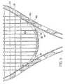
- FIG. 1illustrates a partially strung tennis racquet frame 10 .
- the frameincludes a head portion 12 , whose inwardly facing surface defines an area 13 in which the string bed lies.
- the head portionincludes a throat bridge 14 which encloses the lower portion of the stringing area 13 .
- the head portionis coupled to a handle portion 15 of the frame by a pair of converging shaft members 16 .
- the head portion 12 of the frameincludes elongated cutout portions 18 , 18 a.
- a cutout portion 18is formed along each of the sides of the head section 12 .
- a third cutout portion 18 ais formed in the tip section.
- Each cutout portion 18 , 18 aincludes a slot 20 that extends through the frame 10 in the plane of the string bed, and an outwardly facing shoulder 24 surrounding the slot 20 .
- the shoulder 24which acts as a bearing surface, is depressed relative to the outer surface 26 of the frame 10 and, at each location on the frame, is preferably perpendicular to the direction of the strings entering and leaving the frame. Alternatively, the shoulder 24 may be at an angle other than perpendicular. For example, the shoulder 24 could taper inwardly in the direction toward the string bed.
- one or more support posts 29may span the upper and lower frame portions defining the cutout portions 18 , 18 a.
- Insert members 30 , 30 a, 30 bare received in the cutout portions 18 , 18 a.
- the undersurface of each insert member 30 , 30 abears against the shoulder 24 .
- the insert members 30 , 30 a, 30 bhave a thickness such that their outer surface 31 is generally flush with the outer surface 25 of the frame. However, if desired, the outer surfaces 31 of the insert members may lie above or below the outer surface 25 of the frame.
- the corresponding bearing surfaces of the insert members 18 , 18 aare flat. If the shoulder 24 is tapered or otherwise shaped, the corresponding insert member bearing surface would be tapered or have a corresponding shape. In either case, the function of the bearing surfaces is to prevent the insert members 18 , 18 a from being pulled through the frame when the strings are tensioned.
- Each insert member 30 , 30 a, 30 bincludes a plurality of string port holes 32 and a plurality of conventional string holes 33 .
- Each of the string port holes 32 , 32 aprovides for the passage of two contiguous main string segments or two contiguous cross string segments and has a dimension equal to the desired spacing between two contiguous string segments.
- string segmentrefers to a length of string extending between opposed string holes on the frame.
- the center region of the throat bridge 14is molded to include a plurality of string port holes 32 a, and the opposite ends 35 of the throat bridge are forked to define openings 36 in the plane of the string bed for the passage of the outer main strings 40 .
- the string port holes 32 on opposite sides of the racquet frameare offset relative to one another such that a string extending from one side of a string port hole 32 , after crossing the interwoven string bed, extends along the opposite side of the string port hole 32 on the opposite side of the racquet.
- the insert members 30 , 30 a along the sidescontain seven string port holes 32 along with conventional string holes 33 .
- the insert member 30 b at the tipcontains six string port holes 32 along with conventional string holes 33 .
- FIGS. 1-3are merely exemplary, and the disposition, and number of string port holes 32 and conventional string holes 33 can vary.
- the string port holes 32are rectangular in shape.
- the string port holesmay assume any suitable shape, e.g., any of the shapes shown in WO 2004/075996.
- the shape of the string port holescan be varied in order to create different design patterns in the frame or for other reasons, such as minimizing the cost of tooling or production.
- the outer edges of the string port holes, at least in the string planeare rounded, so that the string does not encounter a sharp edge as it enters and leaves the hole and form a guide anchoring the ends of the strings.
- the outside surfaces of the insert membersinclude a stringing groove 48 , to help guide the strings between string holes, and anchor the ends of the string segments in the holes.
- the surfaces of the string port holes against which the strings bear as they pass throughis flat, as shown in FIGS. 1 and 3 , and oriented so as to be perpendicular to the string bed and parallel to the direction by which the string end passes through the string port hole.
- the string port holescan also be used as seats for the insertion of plastic parts and/or vibration damping elements and/or weights in order to modify the mass distribution of the frame, for example, to change the balance or playing characteristics of the racquet.
- FIG. 1shows a partially strung racquet in order to illustrate why the port string holes need to be offset relative to one another.
- a main string segment 40 aextends through the right hand side of string port hole 32 a to the throat bridge 14 .
- string segment 40 aextends through the left hand side of the string port hole 32 b in the throat bridge 14 and wraps around the outside of the throat bridge 14 .
- next string segment 40 bafter passing through the right-hand side of port string hole 32 c, extends from the throat bridge 14 through the left-hand side of the string port hole 32 a in the insert member 30 b, wraps around the outside of the insert 30 b, and extends through the right-hand side of the next string port hole 32 d.
- outer main string segments 40 cextend through the forked opening 36 in the throat bridge 14 to string holes in the insert members 30 , 30 a.
- the saddle shaped base 38 of the forked opening 36provides a seat for one of the string segments 40 d.
- FIGS. 4-8illustrate a second embodiment of the invention.
- the opposite sides of the head portion 12 a of the frame 10 ainclude cutout portions 18 ′, and the tip region includes a cutout portion 18 a ′, each for receiving a cutout member.
- the throat bridge 14 aincludes a cutout portion 18 b for receiving another insert member.
- the cutout portions 18 ′, 18 a ′are not as long as the cutout portions 18 , 18 a in FIGS. 1-3 , and some of the string holes would be drilled or formed in the frame 10 a in the regions between the cutout portions.
- FIG. 7shows another example of a insert member 30 ′, which is received in one of the cutout portions 18 ′, with corresponding insert members being received in the other cutout portions.
- FIGS. 9-10show a third embodiment in which the inwardly facing walls 50 of the cutout portions 18 ′′, designed to receive insert members, have an undulating shape. As shown in FIG. 10 , the insert members 30 ′′ have undulating side walls 52 to fit in the cutout portions 18 ′′.
- FIGS. 11-12show two more embodiments of the invention, in which the sides and tip of the head portion 12 c and 12 d each have more than one cutout portion 18 ′′′ and 18 ′′′′.
- the inwardly facing walls 50 c of the cutouts 18 ′′′are smooth, whereas in FIG. 12 the walls 50 d are undulating.
- the racquet frameis formed in accordance with a process similar to that described in U.S. published patent application No. US2003/0162613, which is incorporated herein by reference.
- a pair of hollow prepreg tubes 60 , 61 of uncured composite materialare placed between upper and lower mold halves 62 , 64 which, when closed, define an inner mold cavity in the shape of the racquet frame.
- An inflatable bladder member 65extends through each prepreg tube. Each bladder member 65 has a pair of ends that project out of the mold when the mold is closed.
- mold members 66Prior to closing the mold, mold members 66 , in the desired shape of the cutout portions, are positioned between the upper and lower tubes 60 , 61 , in the locations where the cutout portions are desired. The mold is then closed, and the bladders 65 are inflated such that the prepreg tubes 60 , 61 assume the shape of the mold and the insert members 66 . At the same time, the mold is heated in order to cause the composite material to cure.
- the abutting walls of the upper and lower tubes 60 , 61fuse together to form a common interior wall in the string bed plane, except where the mold members 66 keep the walls separated from one another. After molding, the mold members 66 are withdrawn from the frame, leaving the cutout portions.
- a racquet according to the inventioncan also be made according to the processes described in U.S. Pat. No. 6,071,203.
- Such racquet framealso is formed of a pair upper and lower tube halves. However, the tubular frame halves are molded individually and then glued together.
- a racquet according to the inventioncan be made by other methods.
- the framecan be molded from a single tube of prepreg, using an inflation molding process similar to a conventional inflation molding process.
- an inflatable bladderis inserted into a prepreg tube, whereupon the tube is inserted into a mold having the desired shape of the frame, The tube is then inflated to conform to the shape of the mold, as the prepreg material is cured.
- a hollow prepreg tube 70with an inflation bladder 71 therein, is placed in a mold shaped to define cutout blanks 74 with side walls 75 in the shape of cutouts for receiving inserts.
- the cutout blanks 74have a bottom wall 76 formed where opposite sides of the prepreg tube 70 have been fused together during the molding process.
- slots 78are drilled to form finished cutout portions 80 .
- the slots 78are drilled so as to leave an outwardly facing shoulder 82 which can form a bearing surface for the insert members (not shown).
- the framecan be formed by injection molding of composite material containing short, chopped fibers, in accordance with another known process, which allows the cutouts to be molded in directly, without the need to remove a blocking wall after molding.
- the framecan be formed in a conventional manner, e.g., by extruding the frame, and then drilling the string holes and enlarged string holes.
- the framecan be made using a double bladder.
- a prepreg tubeis formed around each bladder.
- both bladdersextend through the interior of a common tube.
- insert mold membersare inserted between the two prepreg tube sections, and then the frame is formed by inflation molding in a conventional manner.
- sidesrefers generally to the regions of the racquet head between the upper and lower corners
- tiprefers generally to the region of the head between the upper corners.
- sides and tipcan include any portion of the sides or tip, or even include a portion of persons might consider to be the corners.
- the shoulder 24 forming a seat for the insert memberis perpendicular to the string
- the cutout portionscan have walls which taper in the direction of the string bed, with the insert members also having tapering walls. The force of the strings, when tensioned, will ensure that the insert member is firmly retained in the cutout portion.
- Another possibilityis to mold the carbon fiber frame of the racquet jointly with pre-formed inserts placed in the mold.
- the insertcannot be removed from the frame.
- this embodimentwould avoid the need for expensive equipment to form the insert with tolerances ensuring a tight fit in the frame openings, in that the frame will adapt to the shape of the inserts.
- the insertswhich can be made of plastic, metal, carbon fiber composites, wood, ceramic, etc., are placed into the mold, at the desired locations, with the prepreg tube. When the prepreg tube is heated and expanded, the epoxy or thermoplastic resin will bond firmly with the insert to retain it permanently in place.
- the characteristics of the insertcan be selected based on the choice of materials. If the insert is plastic, features such as damping, soft hitting feeling, etc., can be realized. If the insert is made of other materials, different characteristics, such as elasticity, will result. All such modifications and variations are intended to be within the scope of the invention, as defined in the following claims.
Landscapes
- Health & Medical Sciences (AREA)
- General Health & Medical Sciences (AREA)
- Physical Education & Sports Medicine (AREA)
- Professional, Industrial, Or Sporting Protective Garments (AREA)
- Golf Clubs (AREA)
- Stringed Musical Instruments (AREA)
- Footwear And Its Accessory, Manufacturing Method And Apparatuses (AREA)
Abstract
Description
Claims (11)
Priority Applications (1)
| Application Number | Priority Date | Filing Date | Title |
|---|---|---|---|
| US11/872,770US7396303B2 (en) | 2005-11-29 | 2007-10-16 | Sports racquet with insert members for anchoring strings |
Applications Claiming Priority (4)
| Application Number | Priority Date | Filing Date | Title |
|---|---|---|---|
| EP05111453AEP1790392B1 (en) | 2005-11-29 | 2005-11-29 | Sport racqet with insert members for anchoring strings |
| EP05111453.6 | 2005-11-29 | ||
| US11/584,199US20070123377A1 (en) | 2005-11-29 | 2006-10-20 | Sports racquet with insert members for anchoring strings |
| US11/872,770US7396303B2 (en) | 2005-11-29 | 2007-10-16 | Sports racquet with insert members for anchoring strings |
Related Parent Applications (1)
| Application Number | Title | Priority Date | Filing Date |
|---|---|---|---|
| US11/584,199ContinuationUS20070123377A1 (en) | 2005-11-29 | 2006-10-20 | Sports racquet with insert members for anchoring strings |
Publications (2)
| Publication Number | Publication Date |
|---|---|
| US20080058131A1 US20080058131A1 (en) | 2008-03-06 |
| US7396303B2true US7396303B2 (en) | 2008-07-08 |
Family
ID=35841899
Family Applications (2)
| Application Number | Title | Priority Date | Filing Date |
|---|---|---|---|
| US11/584,199AbandonedUS20070123377A1 (en) | 2005-11-29 | 2006-10-20 | Sports racquet with insert members for anchoring strings |
| US11/872,770ActiveUS7396303B2 (en) | 2005-11-29 | 2007-10-16 | Sports racquet with insert members for anchoring strings |
Family Applications Before (1)
| Application Number | Title | Priority Date | Filing Date |
|---|---|---|---|
| US11/584,199AbandonedUS20070123377A1 (en) | 2005-11-29 | 2006-10-20 | Sports racquet with insert members for anchoring strings |
Country Status (8)
| Country | Link |
|---|---|
| US (2) | US20070123377A1 (en) |
| EP (1) | EP1790392B1 (en) |
| JP (1) | JP5174342B2 (en) |
| CN (1) | CN1973924B (en) |
| AT (1) | ATE411840T1 (en) |
| AU (1) | AU2006210337B2 (en) |
| DE (1) | DE602005010596D1 (en) |
| ES (1) | ES2315806T3 (en) |
Cited By (14)
| Publication number | Priority date | Publication date | Assignee | Title |
|---|---|---|---|---|
| US20070200422A1 (en)* | 2005-12-09 | 2007-08-30 | Davis Stephen J | Wheel having multiple tube frame structure |
| US20070270253A1 (en)* | 2006-05-22 | 2007-11-22 | Davis Stephen J | Hockey stick system having a multiple tube structure |
| US20070275799A1 (en)* | 2006-05-29 | 2007-11-29 | Davis Stephen J | Hockey stick having a single, hollow primary tube |
| US20070275800A1 (en)* | 2005-07-18 | 2007-11-29 | Davis Stephen J | Composite hockey stick system |
| US20080051230A1 (en)* | 2006-08-26 | 2008-02-28 | Davis Stephen J | Composite bat having a multiple tube structure |
| US20080070725A1 (en)* | 2006-09-20 | 2008-03-20 | Davis Stephen J | Composite bat having a single, hollow primary tube structure |
| US7503860B2 (en) | 2005-11-29 | 2009-03-17 | Prince Sports, Inc. | Sports racquet with multi-section frame |
| US20110165975A1 (en)* | 2007-11-26 | 2011-07-07 | Brett Bothwell | System and Method for a Pre-Formed Reinforcement Member for an Opening in a Game Racket |
| US9132321B2 (en) | 2007-11-26 | 2015-09-15 | Brett Bothwell | System and method for an inflation bladder composite game racket |
| US9320946B2 (en) | 2007-11-26 | 2016-04-26 | Brett Bothwell | System and method for a game racquet including an actuator |
| US20170319911A1 (en)* | 2016-05-06 | 2017-11-09 | Head Technology Gmbh | Bridge for a ball game racket |
| US20170319912A1 (en)* | 2016-05-06 | 2017-11-09 | Head Technology Gmbh | Ball game racket with magnesium bridge |
| US9821197B2 (en) | 2007-11-26 | 2017-11-21 | Brett Bothwell | System and method for a game racquet including a grommet actuator |
| USD910129S1 (en)* | 2019-01-15 | 2021-02-09 | Sumitomo Rubber Industries, Ltd. | Tennis racket |
Families Citing this family (12)
| Publication number | Priority date | Publication date | Assignee | Title |
|---|---|---|---|---|
| EP1790392B1 (en)* | 2005-11-29 | 2008-10-22 | Prince Sports, Inc. | Sport racqet with insert members for anchoring strings |
| US20070270256A1 (en)* | 2006-05-17 | 2007-11-22 | Jinan Kesavan Chullikattu | Sports racquet |
| FR2916360B1 (en)* | 2007-05-24 | 2016-11-18 | Babolat Vs | TENNIS RACKET FRAME, ITS MANUFACTURING METHOD, AND RACKET COMPRISING SUCH A FRAME. |
| US7371197B1 (en)* | 2007-05-25 | 2008-05-13 | Yuan Min An Enterprise Co., Ltd. | Safety racket |
| WO2009004514A1 (en)* | 2007-07-04 | 2009-01-08 | Tec Sportmanagement Ag | Ball-striking implement |
| US20090314387A1 (en)* | 2008-06-20 | 2009-12-24 | Herndon H Brooks | System and method for controlling interaction between surfaces |
| JP5401185B2 (en)* | 2009-06-30 | 2014-01-29 | ヨネックス株式会社 | racket |
| DE102014110656A1 (en)* | 2014-07-29 | 2016-02-04 | Tec Sportmanagement Ag | Ball impact device and method for its production |
| DK3318308T3 (en)* | 2015-06-05 | 2021-12-20 | Yonex Co Ltd | BATHMIN TONKETS |
| JP7180474B2 (en)* | 2019-03-19 | 2022-11-30 | 住友ゴム工業株式会社 | racket |
| TWI814038B (en)* | 2021-07-22 | 2023-09-01 | 陳威融 | shock absorber |
| TW202432208A (en)* | 2023-01-12 | 2024-08-16 | 日商優乃克股份有限公司 | Racket Stands and Rackets |
Citations (17)
| Publication number | Priority date | Publication date | Assignee | Title |
|---|---|---|---|---|
| US2230177A (en) | 1938-12-01 | 1941-01-28 | Caines Percy Charles | Tennis racket |
| US3545756A (en) | 1968-06-07 | 1970-12-08 | Eugene W Nash | Tennis racket with string supports of variable resiliency |
| US3702701A (en) | 1969-08-28 | 1972-11-14 | Maark Corp | Metal tennis racket with plastic throat piece and molded plastic handle |
| US3901507A (en) | 1972-08-02 | 1975-08-26 | Santini Ormieres Jean | Manufacture of metal frames for tennis and other rackets |
| US4182512A (en) | 1975-12-03 | 1980-01-08 | Kuebler & Co. | Racket for playing tennis or similar ball games |
| US4206917A (en) | 1977-10-14 | 1980-06-10 | Guy Guillem | Sports racquet |
| US4394014A (en) | 1981-04-27 | 1983-07-19 | Balaban J A | Tennis racket |
| FR2587626A1 (en) | 1985-09-20 | 1987-03-27 | Condemi Hubert | Racket for ball games, such as a tennis racket |
| US5060944A (en) | 1990-10-26 | 1991-10-29 | Spalding & Evenflo Companies, Inc. | Tennis racket with split frame |
| WO1994026361A1 (en) | 1993-05-14 | 1994-11-24 | Mitsuru Usui | Racket having very large string holes |
| US5435550A (en) | 1995-01-25 | 1995-07-25 | You; Chin-San | Game racket |
| US5467982A (en) | 1993-06-22 | 1995-11-21 | Tseng; Kuni | Tennis racket |
| US6527656B1 (en) | 2001-11-27 | 2003-03-04 | Wilson Sporting Goods Co. | Two-piece grommet assembly for a sports racquet |
| US20050153799A1 (en) | 2004-01-08 | 2005-07-14 | Michael Rigoli | Sports equipment stick with truss construction |
| US6964624B2 (en) | 2003-06-20 | 2005-11-15 | Wilson Sporting Goods Co. | Bumper guard for a sports racquet |
| US20060172828A1 (en) | 2003-02-28 | 2006-08-03 | Mauro Pezzato | Sports racquet with frame openings |
| US20070123377A1 (en) | 2005-11-29 | 2007-05-31 | Roberto Gazzara | Sports racquet with insert members for anchoring strings |
Family Cites Families (3)
| Publication number | Priority date | Publication date | Assignee | Title |
|---|---|---|---|---|
| US6071203A (en) | 1998-08-13 | 2000-06-06 | Prince Sports Group, Inc. | Two piece sports racquet |
| JP2002191723A (en)* | 2000-12-25 | 2002-07-10 | Mizuno Corp | Racket frame |
| US6800239B2 (en) | 2002-02-26 | 2004-10-05 | Prince Sports, Inc. | Method of manufacturing a two piece sports racquet |
- 2005
- 2005-11-29EPEP05111453Apatent/EP1790392B1/enactiveActive
- 2005-11-29ESES05111453Tpatent/ES2315806T3/enactiveActive
- 2005-11-29ATAT05111453Tpatent/ATE411840T1/ennot_activeIP Right Cessation
- 2005-11-29DEDE602005010596Tpatent/DE602005010596D1/enactiveActive
- 2006
- 2006-09-11AUAU2006210337Apatent/AU2006210337B2/ennot_activeCeased
- 2006-10-18CNCN2006101362772Apatent/CN1973924B/enactiveActive
- 2006-10-20USUS11/584,199patent/US20070123377A1/ennot_activeAbandoned
- 2006-11-28JPJP2006320257Apatent/JP5174342B2/enactiveActive
- 2007
- 2007-10-16USUS11/872,770patent/US7396303B2/enactiveActive
Patent Citations (17)
| Publication number | Priority date | Publication date | Assignee | Title |
|---|---|---|---|---|
| US2230177A (en) | 1938-12-01 | 1941-01-28 | Caines Percy Charles | Tennis racket |
| US3545756A (en) | 1968-06-07 | 1970-12-08 | Eugene W Nash | Tennis racket with string supports of variable resiliency |
| US3702701A (en) | 1969-08-28 | 1972-11-14 | Maark Corp | Metal tennis racket with plastic throat piece and molded plastic handle |
| US3901507A (en) | 1972-08-02 | 1975-08-26 | Santini Ormieres Jean | Manufacture of metal frames for tennis and other rackets |
| US4182512A (en) | 1975-12-03 | 1980-01-08 | Kuebler & Co. | Racket for playing tennis or similar ball games |
| US4206917A (en) | 1977-10-14 | 1980-06-10 | Guy Guillem | Sports racquet |
| US4394014A (en) | 1981-04-27 | 1983-07-19 | Balaban J A | Tennis racket |
| FR2587626A1 (en) | 1985-09-20 | 1987-03-27 | Condemi Hubert | Racket for ball games, such as a tennis racket |
| US5060944A (en) | 1990-10-26 | 1991-10-29 | Spalding & Evenflo Companies, Inc. | Tennis racket with split frame |
| WO1994026361A1 (en) | 1993-05-14 | 1994-11-24 | Mitsuru Usui | Racket having very large string holes |
| US5467982A (en) | 1993-06-22 | 1995-11-21 | Tseng; Kuni | Tennis racket |
| US5435550A (en) | 1995-01-25 | 1995-07-25 | You; Chin-San | Game racket |
| US6527656B1 (en) | 2001-11-27 | 2003-03-04 | Wilson Sporting Goods Co. | Two-piece grommet assembly for a sports racquet |
| US20060172828A1 (en) | 2003-02-28 | 2006-08-03 | Mauro Pezzato | Sports racquet with frame openings |
| US6964624B2 (en) | 2003-06-20 | 2005-11-15 | Wilson Sporting Goods Co. | Bumper guard for a sports racquet |
| US20050153799A1 (en) | 2004-01-08 | 2005-07-14 | Michael Rigoli | Sports equipment stick with truss construction |
| US20070123377A1 (en) | 2005-11-29 | 2007-05-31 | Roberto Gazzara | Sports racquet with insert members for anchoring strings |
Non-Patent Citations (1)
| Title |
|---|
| European Search Report for case EP 05111453, which is the European counterpart of the parent application, 11/ 584, 199, Mar. 2006. |
Cited By (21)
| Publication number | Priority date | Publication date | Assignee | Title |
|---|---|---|---|---|
| US20070275800A1 (en)* | 2005-07-18 | 2007-11-29 | Davis Stephen J | Composite hockey stick system |
| US7727096B2 (en) | 2005-07-18 | 2010-06-01 | Prince Sports, Inc. | Composite hockey stick system |
| US7503860B2 (en) | 2005-11-29 | 2009-03-17 | Prince Sports, Inc. | Sports racquet with multi-section frame |
| US20070200422A1 (en)* | 2005-12-09 | 2007-08-30 | Davis Stephen J | Wheel having multiple tube frame structure |
| US20070270253A1 (en)* | 2006-05-22 | 2007-11-22 | Davis Stephen J | Hockey stick system having a multiple tube structure |
| US7909713B2 (en) | 2006-05-22 | 2011-03-22 | Prince Sports, Inc. | Shaft for a sports stick such as a hockey stick |
| US20070275799A1 (en)* | 2006-05-29 | 2007-11-29 | Davis Stephen J | Hockey stick having a single, hollow primary tube |
| US7727095B2 (en) | 2006-05-29 | 2010-06-01 | Prince Sports, Inc. | Hockey stick having a single, hollow primary tube |
| US7883434B2 (en) | 2006-08-26 | 2011-02-08 | Prince Sports, Inc. | Composite bat having a multiple tube structure |
| US20080051230A1 (en)* | 2006-08-26 | 2008-02-28 | Davis Stephen J | Composite bat having a multiple tube structure |
| US20080070725A1 (en)* | 2006-09-20 | 2008-03-20 | Davis Stephen J | Composite bat having a single, hollow primary tube structure |
| US7575527B2 (en) | 2006-09-20 | 2009-08-18 | Prince Sports, Inc. | Composite bat having a single, hollow primary tube structure |
| US20110165975A1 (en)* | 2007-11-26 | 2011-07-07 | Brett Bothwell | System and Method for a Pre-Formed Reinforcement Member for an Opening in a Game Racket |
| US9132321B2 (en) | 2007-11-26 | 2015-09-15 | Brett Bothwell | System and method for an inflation bladder composite game racket |
| US9320946B2 (en) | 2007-11-26 | 2016-04-26 | Brett Bothwell | System and method for a game racquet including an actuator |
| US9821197B2 (en) | 2007-11-26 | 2017-11-21 | Brett Bothwell | System and method for a game racquet including a grommet actuator |
| US20170319911A1 (en)* | 2016-05-06 | 2017-11-09 | Head Technology Gmbh | Bridge for a ball game racket |
| US20170319912A1 (en)* | 2016-05-06 | 2017-11-09 | Head Technology Gmbh | Ball game racket with magnesium bridge |
| US10143897B2 (en)* | 2016-05-06 | 2018-12-04 | Head Technology Gmbh | Bridge for a ball game racket |
| US10369423B2 (en)* | 2016-05-06 | 2019-08-06 | Head Technology Gmbh | Ball game racket with magnesium bridge |
| USD910129S1 (en)* | 2019-01-15 | 2021-02-09 | Sumitomo Rubber Industries, Ltd. | Tennis racket |
Also Published As
| Publication number | Publication date |
|---|---|
| EP1790392A1 (en) | 2007-05-30 |
| US20080058131A1 (en) | 2008-03-06 |
| HK1107294A1 (en) | 2008-04-03 |
| CN1973924B (en) | 2010-12-01 |
| US20070123377A1 (en) | 2007-05-31 |
| DE602005010596D1 (en) | 2008-12-04 |
| JP2007144187A (en) | 2007-06-14 |
| CN1973924A (en) | 2007-06-06 |
| ATE411840T1 (en) | 2008-11-15 |
| JP5174342B2 (en) | 2013-04-03 |
| EP1790392B1 (en) | 2008-10-22 |
| AU2006210337A1 (en) | 2007-06-14 |
| ES2315806T3 (en) | 2009-04-01 |
| AU2006210337B2 (en) | 2012-07-12 |
Similar Documents
| Publication | Publication Date | Title |
|---|---|---|
| US7396303B2 (en) | Sports racquet with insert members for anchoring strings | |
| US7309299B2 (en) | Sports racquet with frame openings | |
| US8889056B2 (en) | Sports racquet with string port holes | |
| US8079924B2 (en) | Sports racquet with multi-section frame | |
| US8038551B2 (en) | Method for manufacturing a racquet frame for sports racquet and a racquet frame thereof | |
| JP4295053B2 (en) | Sports racket | |
| US7140984B2 (en) | Racket for ball games and production process | |
| JPS63317166A (en) | Cassette racket | |
| US20190091521A1 (en) | Racquet Flex Control Device | |
| HK1087958B (en) | Sports racquet with frame openings | |
| HK1151758A (en) | An improved sports racquet structure | |
| HK1107295B (en) | Sports racquet with multi-section frame | |
| HK1107680B (en) | A sports racquet with string port holes and a method for fabricating such a sports racquet |
Legal Events
| Date | Code | Title | Description |
|---|---|---|---|
| STCF | Information on status: patent grant | Free format text:PATENTED CASE | |
| AS | Assignment | Owner name:GENERAL ELECTRIC CAPITAL CORPORATION, AS AGENT, IL Free format text:SECURITY AGREEMENT;ASSIGNOR:PRINCE SPORTS, INC.;REEL/FRAME:022442/0148 Effective date:20090320 Owner name:GENERAL ELECTRIC CAPITAL CORPORATION, AS AGENT,ILL Free format text:SECURITY AGREEMENT;ASSIGNOR:PRINCE SPORTS, INC.;REEL/FRAME:022442/0148 Effective date:20090320 | |
| FEPP | Fee payment procedure | Free format text:PAYOR NUMBER ASSIGNED (ORIGINAL EVENT CODE: ASPN); ENTITY STATUS OF PATENT OWNER: SMALL ENTITY | |
| AS | Assignment | Owner name:GENERAL ELECTRIC CAPITAL CORPORATION, AS AGENT, IL Free format text:SECURITY AGREEMENT;ASSIGNOR:PRINCE SPORTS, INC.;REEL/FRAME:026460/0056 Effective date:20110614 | |
| FPAY | Fee payment | Year of fee payment:4 | |
| AS | Assignment | Owner name:PRINCE SPORTS, LLC., NEW YORK Free format text:CHANGE OF NAME;ASSIGNOR:PRINCE SPORTS, INC.;REEL/FRAME:030208/0940 Effective date:20120803 | |
| AS | Assignment | Owner name:KEYBANK NATIONAL ASSOCIATION, OHIO Free format text:PATENT SECURITY AGREEMENT;ASSIGNOR:PRINCE SPORTS, LLC;REEL/FRAME:030889/0864 Effective date:20130628 | |
| AS | Assignment | Owner name:PRINCE SPORTS, INC. (NOW KNOWN AS PRINCE SPORTS, L Free format text:NOTICE OF RELEASE OF SECURITY INTEREST BY BANKRUPTCY COURT ORDER (RELEASES RF 022442/0148);ASSIGNOR:GENERAL ELECTRIC CAPITAL CORPORATION;REEL/FRAME:031004/0218 Effective date:20120804 Owner name:PRINCE SPORTS, INC. (NOW KNOWN AS PRINCE SPORTS, L Free format text:NOTICE OF RELEASE OF SECURITY INTEREST BY BANKRUPTCY COURT ORDER (RELEASES RF 026460/0056);ASSIGNOR:GENERAL ELECTRIC CAPITAL CORPORATION;REEL/FRAME:031004/0423 Effective date:20120804 | |
| AS | Assignment | Owner name:PRINCE SPORTS, LLC, NEW YORK Free format text:RELEASE OF SECURITY INTEREST;ASSIGNOR:KEYBANK NATIONAL ASSOCIATION;REEL/FRAME:033053/0714 Effective date:20140527 | |
| AS | Assignment | Owner name:BANK OF AMERICA, N.A., AS COLLATERAL AGENT, NORTH Free format text:FIRST LIEN SECURITY AGREEMENT;ASSIGNOR:PRINCE SPORTS, LLC;REEL/FRAME:033063/0732 Effective date:20140527 | |
| AS | Assignment | Owner name:BANK OF AMERICA, N.A., AS COLLATERAL AGENT, NORTH Free format text:SECOND LIEN SECURITY AGREEMENT;ASSIGNOR:PRINCE SPORTS, LLC;REEL/FRAME:033073/0369 Effective date:20140527 | |
| AS | Assignment | Owner name:PRINCE SPORTS, INC., NEW JERSEY Free format text:ASSIGNMENT OF ASSIGNORS INTEREST;ASSIGNORS:GAZZARA, ROBERTO;PINAFFO, MAURO;POZZOBON, MICHELE;AND OTHERS;REEL/FRAME:035144/0277 Effective date:20070213 | |
| FEPP | Fee payment procedure | Free format text:PAT HOLDER NO LONGER CLAIMS SMALL ENTITY STATUS, ENTITY STATUS SET TO UNDISCOUNTED (ORIGINAL EVENT CODE: STOL); ENTITY STATUS OF PATENT OWNER: SMALL ENTITY | |
| FPAY | Fee payment | Year of fee payment:8 | |
| AS | Assignment | Owner name:BANK OF AMERICA, N.A., NORTH CAROLINA Free format text:LIEN;ASSIGNORS:PRINCE SPORTS, LLC;ABG-SPORTCRAFT, LLC;ABG-TRETORN, LLC;REEL/FRAME:043824/0236 Effective date:20170929 Owner name:ABG-SPORTCRAFT, LLC, NEW JERSEY Free format text:RELEASE BY SECURED PARTY;ASSIGNOR:BANK OF AMERICA, N.A.;REEL/FRAME:044169/0080 Effective date:20170929 Owner name:ABG-TRETORN, LLC, NEW YORK Free format text:RELEASE BY SECURED PARTY;ASSIGNOR:BANK OF AMERICA, N.A.;REEL/FRAME:044169/0080 Effective date:20170929 Owner name:PRINCE SPORTS, LLC, GEORGIA Free format text:RELEASE BY SECURED PARTY;ASSIGNOR:BANK OF AMERICA, N.A.;REEL/FRAME:044169/0080 Effective date:20170929 | |
| AS | Assignment | Owner name:BANK OF AMERICA, N.A., NORTH CAROLINA Free format text:LIEN;ASSIGNORS:PRINCE SPORTS, LLC;ABG-SPORTCRAFT, LLC;ABG-TRETORN, LLC;REEL/FRAME:043834/0343 Effective date:20170929 Owner name:PRINCE SPORTS, LLC, NEW YORK Free format text:RELEASE BY SECURED PARTY;ASSIGNOR:BANK OF AMERICA, N.A.;REEL/FRAME:044219/0220 Effective date:20170929 Owner name:ABG-TRETORN, LLC, NEW YORK Free format text:RELEASE BY SECURED PARTY;ASSIGNOR:BANK OF AMERICA, N.A.;REEL/FRAME:044219/0220 Effective date:20170929 Owner name:ABG-SPORTCRAFT, LLC, NEW YORK Free format text:RELEASE BY SECURED PARTY;ASSIGNOR:BANK OF AMERICA, N.A.;REEL/FRAME:044219/0220 Effective date:20170929 | |
| FEPP | Fee payment procedure | Free format text:ENTITY STATUS SET TO SMALL (ORIGINAL EVENT CODE: SMAL); ENTITY STATUS OF PATENT OWNER: SMALL ENTITY | |
| FEPP | Fee payment procedure | Free format text:11.5 YR SURCHARGE- LATE PMT W/IN 6 MO, SMALL ENTITY (ORIGINAL EVENT CODE: M2556); ENTITY STATUS OF PATENT OWNER: SMALL ENTITY | |
| MAFP | Maintenance fee payment | Free format text:PAYMENT OF MAINTENANCE FEE, 12TH YR, SMALL ENTITY (ORIGINAL EVENT CODE: M2553); ENTITY STATUS OF PATENT OWNER: SMALL ENTITY Year of fee payment:12 | |
| AS | Assignment | Owner name:BANK OF AMERICA, N.A., NORTH CAROLINA Free format text:SECURITY INTEREST;ASSIGNORS:ABG-SPORTCRAFT, LLC;PRINCE SPORTS, LLC;ABG-NINE WEST, LLC;REEL/FRAME:059514/0553 Effective date:20220224 | |
| AS | Assignment | Owner name:ABG-NINE WEST, LLC, NEW YORK Free format text:RELEASE BY SECURED PARTY;ASSIGNOR:BANK OF AMERICA, N. A.;REEL/FRAME:065963/0478 Effective date:20231220 Owner name:PRINCE SPORTS, LLC, NEW YORK Free format text:RELEASE BY SECURED PARTY;ASSIGNOR:BANK OF AMERICA, N. A.;REEL/FRAME:065963/0478 Effective date:20231220 Owner name:ABG-SPORTCRAFT, LLC, NEW YORK Free format text:RELEASE BY SECURED PARTY;ASSIGNOR:BANK OF AMERICA, N. A.;REEL/FRAME:065963/0478 Effective date:20231220 |