US7395790B2 - Reed valve breather for evolution engine - Google Patents
Reed valve breather for evolution engineDownload PDFInfo
- Publication number
- US7395790B2 US7395790B2US11/008,208US820804AUS7395790B2US 7395790 B2US7395790 B2US 7395790B2US 820804 AUS820804 AUS 820804AUS 7395790 B2US7395790 B2US 7395790B2
- Authority
- US
- United States
- Prior art keywords
- reed valve
- valve assembly
- opening
- flexible member
- engine
- Prior art date
- Legal status (The legal status is an assumption and is not a legal conclusion. Google has not performed a legal analysis and makes no representation as to the accuracy of the status listed.)
- Expired - Lifetime
Links
- 235000014676Phragmites communisNutrition0.000titleclaimsabstractdescription111
- 239000012530fluidSubstances0.000claimsdescription9
- 229910000831SteelInorganic materials0.000claimsdescription5
- 238000004891communicationMethods0.000claimsdescription5
- 238000000034methodMethods0.000claimsdescription5
- 239000010959steelSubstances0.000claimsdescription5
- 229910001369BrassInorganic materials0.000claimsdescription2
- 229920000049Carbon (fiber)Polymers0.000claimsdescription2
- RTAQQCXQSZGOHL-UHFFFAOYSA-NTitaniumChemical compound[Ti]RTAQQCXQSZGOHL-UHFFFAOYSA-N0.000claimsdescription2
- 229910052782aluminiumInorganic materials0.000claimsdescription2
- XAGFODPZIPBFFR-UHFFFAOYSA-NaluminiumChemical compound[Al]XAGFODPZIPBFFR-UHFFFAOYSA-N0.000claimsdescription2
- 239000010951brassSubstances0.000claimsdescription2
- 239000004917carbon fiberSubstances0.000claimsdescription2
- 238000005520cutting processMethods0.000claimsdescription2
- 239000011152fibreglassSubstances0.000claimsdescription2
- VNWKTOKETHGBQD-UHFFFAOYSA-NmethaneChemical compoundCVNWKTOKETHGBQD-UHFFFAOYSA-N0.000claimsdescription2
- 239000004033plasticSubstances0.000claimsdescription2
- 239000010936titaniumSubstances0.000claimsdescription2
- 229910052719titaniumInorganic materials0.000claimsdescription2
- 238000005266castingMethods0.000claims1
- 230000000712assemblyEffects0.000description13
- 238000000429assemblyMethods0.000description13
- 239000000463materialSubstances0.000description7
- 238000009434installationMethods0.000description5
- 125000006850spacer groupChemical group0.000description5
- 238000005452bendingMethods0.000description4
- 230000008901benefitEffects0.000description3
- 238000003754machiningMethods0.000description3
- 230000035484reaction timeEffects0.000description3
- 230000008030eliminationEffects0.000description2
- 238000003379elimination reactionMethods0.000description2
- 238000011900installation processMethods0.000description2
- 238000012986modificationMethods0.000description2
- 230000004048modificationEffects0.000description2
- 230000008569processEffects0.000description2
- 230000029058respiratory gaseous exchangeEffects0.000description2
- 238000007789sealingMethods0.000description2
- 229910000975Carbon steelInorganic materials0.000description1
- 206010008469Chest discomfortDiseases0.000description1
- 238000009825accumulationMethods0.000description1
- 239000000956alloySubstances0.000description1
- 229910045601alloyInorganic materials0.000description1
- 239000010962carbon steelSubstances0.000description1
- 238000002485combustion reactionMethods0.000description1
- 239000002131composite materialSubstances0.000description1
- 230000001010compromised effectEffects0.000description1
- 239000013013elastic materialSubstances0.000description1
- 230000037406food intakeEffects0.000description1
- 238000004519manufacturing processMethods0.000description1
- 229910052751metalInorganic materials0.000description1
- 239000007769metal materialSubstances0.000description1
- 239000003595mistSubstances0.000description1
- 230000037361pathwayEffects0.000description1
- 230000008439repair processEffects0.000description1
- 230000004044responseEffects0.000description1
- 239000000779smokeSubstances0.000description1
- 230000000391smoking effectEffects0.000description1
- 239000007787solidSubstances0.000description1
- 239000010935stainless steelSubstances0.000description1
- 229910001220stainless steelInorganic materials0.000description1
- 238000009423ventilationMethods0.000description1
Images


Classifications
- F—MECHANICAL ENGINEERING; LIGHTING; HEATING; WEAPONS; BLASTING
- F01—MACHINES OR ENGINES IN GENERAL; ENGINE PLANTS IN GENERAL; STEAM ENGINES
- F01L—CYCLICALLY OPERATING VALVES FOR MACHINES OR ENGINES
- F01L1/00—Valve-gear or valve arrangements, e.g. lift-valve gear
- F01L1/02—Valve drive
- F—MECHANICAL ENGINEERING; LIGHTING; HEATING; WEAPONS; BLASTING
- F01—MACHINES OR ENGINES IN GENERAL; ENGINE PLANTS IN GENERAL; STEAM ENGINES
- F01L—CYCLICALLY OPERATING VALVES FOR MACHINES OR ENGINES
- F01L1/00—Valve-gear or valve arrangements, e.g. lift-valve gear
- F01L1/02—Valve drive
- F01L1/024—Belt drive
- F—MECHANICAL ENGINEERING; LIGHTING; HEATING; WEAPONS; BLASTING
- F01—MACHINES OR ENGINES IN GENERAL; ENGINE PLANTS IN GENERAL; STEAM ENGINES
- F01L—CYCLICALLY OPERATING VALVES FOR MACHINES OR ENGINES
- F01L1/00—Valve-gear or valve arrangements, e.g. lift-valve gear
- F01L1/12—Transmitting gear between valve drive and valve
- F01L1/14—Tappets; Push rods
- F01L1/146—Push-rods
- F—MECHANICAL ENGINEERING; LIGHTING; HEATING; WEAPONS; BLASTING
- F01—MACHINES OR ENGINES IN GENERAL; ENGINE PLANTS IN GENERAL; STEAM ENGINES
- F01M—LUBRICATING OF MACHINES OR ENGINES IN GENERAL; LUBRICATING INTERNAL COMBUSTION ENGINES; CRANKCASE VENTILATING
- F01M1/00—Pressure lubrication
- F01M1/06—Lubricating systems characterised by the provision therein of crankshafts or connecting rods with lubricant passageways, e.g. bores
- F—MECHANICAL ENGINEERING; LIGHTING; HEATING; WEAPONS; BLASTING
- F02—COMBUSTION ENGINES; HOT-GAS OR COMBUSTION-PRODUCT ENGINE PLANTS
- F02B—INTERNAL-COMBUSTION PISTON ENGINES; COMBUSTION ENGINES IN GENERAL
- F02B61/00—Adaptations of engines for driving vehicles or for driving propellers; Combinations of engines with gearing
- F02B61/02—Adaptations of engines for driving vehicles or for driving propellers; Combinations of engines with gearing for driving cycles
- F—MECHANICAL ENGINEERING; LIGHTING; HEATING; WEAPONS; BLASTING
- F02—COMBUSTION ENGINES; HOT-GAS OR COMBUSTION-PRODUCT ENGINE PLANTS
- F02B—INTERNAL-COMBUSTION PISTON ENGINES; COMBUSTION ENGINES IN GENERAL
- F02B75/00—Other engines
- F02B75/16—Engines characterised by number of cylinders, e.g. single-cylinder engines
- F02B75/18—Multi-cylinder engines
- F02B75/22—Multi-cylinder engines with cylinders in V, fan, or star arrangement
- F—MECHANICAL ENGINEERING; LIGHTING; HEATING; WEAPONS; BLASTING
- F02—COMBUSTION ENGINES; HOT-GAS OR COMBUSTION-PRODUCT ENGINE PLANTS
- F02M—SUPPLYING COMBUSTION ENGINES IN GENERAL WITH COMBUSTIBLE MIXTURES OR CONSTITUENTS THEREOF
- F02M35/00—Combustion-air cleaners, air intakes, intake silencers, or induction systems specially adapted for, or arranged on, internal-combustion engines
- F02M35/10—Air intakes; Induction systems
- F02M35/104—Intake manifolds
- F02M35/116—Intake manifolds for engines with cylinders in V-arrangement or arranged oppositely relative to the main shaft
- F—MECHANICAL ENGINEERING; LIGHTING; HEATING; WEAPONS; BLASTING
- F16—ENGINEERING ELEMENTS AND UNITS; GENERAL MEASURES FOR PRODUCING AND MAINTAINING EFFECTIVE FUNCTIONING OF MACHINES OR INSTALLATIONS; THERMAL INSULATION IN GENERAL
- F16K—VALVES; TAPS; COCKS; ACTUATING-FLOATS; DEVICES FOR VENTING OR AERATING
- F16K15/00—Check valves
- F16K15/14—Check valves with flexible valve members
- F16K15/16—Check valves with flexible valve members with tongue-shaped laminae
- F—MECHANICAL ENGINEERING; LIGHTING; HEATING; WEAPONS; BLASTING
- F01—MACHINES OR ENGINES IN GENERAL; ENGINE PLANTS IN GENERAL; STEAM ENGINES
- F01L—CYCLICALLY OPERATING VALVES FOR MACHINES OR ENGINES
- F01L1/00—Valve-gear or valve arrangements, e.g. lift-valve gear
- F01L1/02—Valve drive
- F01L1/04—Valve drive by means of cams, camshafts, cam discs, eccentrics or the like
- F01L1/047—Camshafts
- F—MECHANICAL ENGINEERING; LIGHTING; HEATING; WEAPONS; BLASTING
- F01—MACHINES OR ENGINES IN GENERAL; ENGINE PLANTS IN GENERAL; STEAM ENGINES
- F01L—CYCLICALLY OPERATING VALVES FOR MACHINES OR ENGINES
- F01L1/00—Valve-gear or valve arrangements, e.g. lift-valve gear
- F01L1/12—Transmitting gear between valve drive and valve
- F01L1/18—Rocking arms or levers
- F01L1/181—Centre pivot rocking arms
- F01L1/182—Centre pivot rocking arms the rocking arm being pivoted about an individual fulcrum, i.e. not about a common shaft
- F—MECHANICAL ENGINEERING; LIGHTING; HEATING; WEAPONS; BLASTING
- F01—MACHINES OR ENGINES IN GENERAL; ENGINE PLANTS IN GENERAL; STEAM ENGINES
- F01L—CYCLICALLY OPERATING VALVES FOR MACHINES OR ENGINES
- F01L1/00—Valve-gear or valve arrangements, e.g. lift-valve gear
- F01L1/02—Valve drive
- F01L1/04—Valve drive by means of cams, camshafts, cam discs, eccentrics or the like
- F01L1/047—Camshafts
- F01L2001/054—Camshafts in cylinder block
- F—MECHANICAL ENGINEERING; LIGHTING; HEATING; WEAPONS; BLASTING
- F01—MACHINES OR ENGINES IN GENERAL; ENGINE PLANTS IN GENERAL; STEAM ENGINES
- F01L—CYCLICALLY OPERATING VALVES FOR MACHINES OR ENGINES
- F01L2301/00—Using particular materials
- F—MECHANICAL ENGINEERING; LIGHTING; HEATING; WEAPONS; BLASTING
- F01—MACHINES OR ENGINES IN GENERAL; ENGINE PLANTS IN GENERAL; STEAM ENGINES
- F01L—CYCLICALLY OPERATING VALVES FOR MACHINES OR ENGINES
- F01L2305/00—Valve arrangements comprising rollers
- F—MECHANICAL ENGINEERING; LIGHTING; HEATING; WEAPONS; BLASTING
- F02—COMBUSTION ENGINES; HOT-GAS OR COMBUSTION-PRODUCT ENGINE PLANTS
- F02B—INTERNAL-COMBUSTION PISTON ENGINES; COMBUSTION ENGINES IN GENERAL
- F02B2275/00—Other engines, components or details, not provided for in other groups of this subclass
- F02B2275/10—Diamond configuration of valves in cylinder heads
- F—MECHANICAL ENGINEERING; LIGHTING; HEATING; WEAPONS; BLASTING
- F02—COMBUSTION ENGINES; HOT-GAS OR COMBUSTION-PRODUCT ENGINE PLANTS
- F02F—CYLINDERS, PISTONS OR CASINGS, FOR COMBUSTION ENGINES; ARRANGEMENTS OF SEALINGS IN COMBUSTION ENGINES
- F02F7/00—Casings, e.g. crankcases
- F02F7/0043—Arrangements of mechanical drive elements
- F02F7/0053—Crankshaft bearings fitted in the crankcase
- F—MECHANICAL ENGINEERING; LIGHTING; HEATING; WEAPONS; BLASTING
- F02—COMBUSTION ENGINES; HOT-GAS OR COMBUSTION-PRODUCT ENGINE PLANTS
- F02M—SUPPLYING COMBUSTION ENGINES IN GENERAL WITH COMBUSTIBLE MIXTURES OR CONSTITUENTS THEREOF
- F02M35/00—Combustion-air cleaners, air intakes, intake silencers, or induction systems specially adapted for, or arranged on, internal-combustion engines
- F02M35/10—Air intakes; Induction systems
- F02M35/10314—Materials for intake systems
- F02M35/10321—Plastics; Composites; Rubbers
- F—MECHANICAL ENGINEERING; LIGHTING; HEATING; WEAPONS; BLASTING
- F02—COMBUSTION ENGINES; HOT-GAS OR COMBUSTION-PRODUCT ENGINE PLANTS
- F02M—SUPPLYING COMBUSTION ENGINES IN GENERAL WITH COMBUSTIBLE MIXTURES OR CONSTITUENTS THEREOF
- F02M35/00—Combustion-air cleaners, air intakes, intake silencers, or induction systems specially adapted for, or arranged on, internal-combustion engines
- F02M35/10—Air intakes; Induction systems
- F02M35/10314—Materials for intake systems
- F02M35/10327—Metals; Alloys
- F—MECHANICAL ENGINEERING; LIGHTING; HEATING; WEAPONS; BLASTING
- F02—COMBUSTION ENGINES; HOT-GAS OR COMBUSTION-PRODUCT ENGINE PLANTS
- F02M—SUPPLYING COMBUSTION ENGINES IN GENERAL WITH COMBUSTIBLE MIXTURES OR CONSTITUENTS THEREOF
- F02M35/00—Combustion-air cleaners, air intakes, intake silencers, or induction systems specially adapted for, or arranged on, internal-combustion engines
- F02M35/10—Air intakes; Induction systems
- F02M35/1034—Manufacturing and assembling intake systems
- F02M35/10347—Moulding, casting or the like
- F—MECHANICAL ENGINEERING; LIGHTING; HEATING; WEAPONS; BLASTING
- F02—COMBUSTION ENGINES; HOT-GAS OR COMBUSTION-PRODUCT ENGINE PLANTS
- F02M—SUPPLYING COMBUSTION ENGINES IN GENERAL WITH COMBUSTIBLE MIXTURES OR CONSTITUENTS THEREOF
- F02M35/00—Combustion-air cleaners, air intakes, intake silencers, or induction systems specially adapted for, or arranged on, internal-combustion engines
- F02M35/10—Air intakes; Induction systems
- F02M35/1034—Manufacturing and assembling intake systems
- F02M35/10367—Machining, e.g. milling, grinding, punching, sanding; Bending; Surface treatments
- F—MECHANICAL ENGINEERING; LIGHTING; HEATING; WEAPONS; BLASTING
- F02—COMBUSTION ENGINES; HOT-GAS OR COMBUSTION-PRODUCT ENGINE PLANTS
- F02M—SUPPLYING COMBUSTION ENGINES IN GENERAL WITH COMBUSTIBLE MIXTURES OR CONSTITUENTS THEREOF
- F02M35/00—Combustion-air cleaners, air intakes, intake silencers, or induction systems specially adapted for, or arranged on, internal-combustion engines
- F02M35/16—Combustion-air cleaners, air intakes, intake silencers, or induction systems specially adapted for, or arranged on, internal-combustion engines characterised by use in vehicles
- F02M35/162—Motorcycles; All-terrain vehicles, e.g. quads, snowmobiles; Small vehicles, e.g. forklifts
- Y—GENERAL TAGGING OF NEW TECHNOLOGICAL DEVELOPMENTS; GENERAL TAGGING OF CROSS-SECTIONAL TECHNOLOGIES SPANNING OVER SEVERAL SECTIONS OF THE IPC; TECHNICAL SUBJECTS COVERED BY FORMER USPC CROSS-REFERENCE ART COLLECTIONS [XRACs] AND DIGESTS
- Y10—TECHNICAL SUBJECTS COVERED BY FORMER USPC
- Y10T—TECHNICAL SUBJECTS COVERED BY FORMER US CLASSIFICATION
- Y10T137/00—Fluid handling
- Y10T137/7722—Line condition change responsive valves
- Y10T137/7837—Direct response valves [i.e., check valve type]
- Y10T137/7838—Plural
- Y—GENERAL TAGGING OF NEW TECHNOLOGICAL DEVELOPMENTS; GENERAL TAGGING OF CROSS-SECTIONAL TECHNOLOGIES SPANNING OVER SEVERAL SECTIONS OF THE IPC; TECHNICAL SUBJECTS COVERED BY FORMER USPC CROSS-REFERENCE ART COLLECTIONS [XRACs] AND DIGESTS
- Y10—TECHNICAL SUBJECTS COVERED BY FORMER USPC
- Y10T—TECHNICAL SUBJECTS COVERED BY FORMER US CLASSIFICATION
- Y10T137/00—Fluid handling
- Y10T137/7722—Line condition change responsive valves
- Y10T137/7837—Direct response valves [i.e., check valve type]
- Y10T137/785—With retarder or dashpot
Definitions
- the present inventionrelates generally to reed valve assemblies, and more particularly to motorcycle reed valve assemblies.
- Breather valves for motorcycle engineshave been used for many years.
- the purpose of a breather valveis generally twofold. First, it expels air and oil from the crank region, on the down stroke of the pistons, to the gear case where the oil lubricates various gears and other parts. Second, it draws oil from the bottom of the oil separating pocket (also sometimes referred to as the “settling pocket”) in the bottom of the gear case.
- Exemplary breather valvesare described in U.S. Pat. No. 6,189,496; U.S. Pat. No. 6,457,449 and U.S. Published Patent Application No. 20040123823, which are all incorporated by reference herein in their entirety.
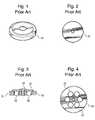
- FIGS. 1-4An exemplary known breather valve 10 is shown in FIGS. 1-4 .
- the illustrated breather valve 10is commonly known as a “flapper” breather valve, because it includes a flexible member 21 which is commonly referred to as a flapper by those of skill in the relevant art.
- breather valve 10includes a body 19 with a plurality of bores 22 formed therein. The bores 22 in body 19 are sealed via flexible member 21 , which is coupled to a top surface of the body 19 via fastener 23 . In operation, the flexible member 21 flexes to selectively cut off or open air and/or oil flow to/from bores 22 .
- valve assembliessuch as rotary breather gears (not shown) are typically designed for engines operating at specific revolution per minute (RPM) ranges. Such a configuration, however, is disadvantageous for engines typically operating at lower RPM ranges, at higher RPM ranges, or wide RPM ranges—i.e., ranges different from the optimized ranges of known valve assemblies. Further, many known valve assemblies suffer from relatively high engine noise during operation. This can be a significant problem with gear driven rotary breather valves primarily due to gear meshing from the gear driven arrangement.
- known valve assembliesdo not sufficiently protect against engine damage during engine failure, which adds to the cost and complexity of repairing damaged engines.
- debriscan pass through the breather passage and become trapped between the breather gear and the bore. Trapped debris can tear up the bore, which then requires machining and an oversized replacement part to repair the damage from the trapped debris.
- FIGS. 1-4depict a known breather valve.
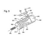
- FIG. 5is an exploded assembly view of a rotatably mounted reed valve assembly according to an embodiment of the present invention.
- FIG. 6is a bottom view of the reed valve assembly of FIG. 5 .
- FIG. 7is a top view of the reed valve assembly of FIG. 5 .
- FIG. 8is a side view of the reed valve assembly of FIG. 5 .
- FIG. 9is a perspective view of the reed valve assembly of FIG. 5 .
- FIG. 10depicts a crank case with the reed valve assembly of FIG. 5 installed therein.
- FIGS. 11-14depict a known fixed mounted reed valve.
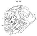
- FIG. 15depicts a crank case with the reed valve assembly of FIG. 11 installed therein according to an embodiment of the present invention.
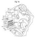
- FIG. 16depicts a crank case with a reed valve assembly according to another embodiment of the present invention installed therein.
- a reed valve assembly 600according to a first embodiment of the present invention is shown in FIGS. 5-9 .
- the reed valve assembly 600may be used to replace a conventional breather valve in an existing motorcycle crank case 100 (see FIG. 10 ). i.e., the reed valve assembly 600 may have a periphery so as to be interchangeable with a conventional breather valve. Alternatively, reed valve assembly 600 may be provided with or sold for use in a new motorcycle crank case 100 .
- Other configurations and usesare also contemplated, including non-motorcycle applications such as all terrain vehicles (ATVs), automobiles, farm equipment, generators, law mowers, etc.
- the reed valve assembly 600includes an elongated body 640 with a first end 610 and a second end 620 .
- the body 640(and/or other components of the assembly) can be formed of any solid metal, alloy or composite material.
- a materialshould be selected that can withstand common engine temperatures (e.g., about 300° F.) and an oil-rich environment.
- the material selectedmay be heat treated and/or surface finished to enhance fatigue resistance depending on the particular application at hand.
- Exemplary materials suitable for various embodiments of the present inventioninclude stainless steel, carbon steel, aluminum, brass, titanium, fiberglass, carbon fiber, and plastic. Other materials are also contemplated.
- An internal cavity 650is formed within the body 640 , internal cavity 650 extending from the second end 620 toward the first end 610 .
- the cavity 650may include a hole substantially in the center of the cavity 650 as shown best in FIG. 6 . This hole provides spacing for cutting a taper in the body 640 , makes manufacturing easier, and reduces the weight of the reed valve assembly 600 .
- the internal cavity 650is adapted and configured to act as a conduit through which fluid (e.g., oil) and/or gas (e.g., air) passes between a crank region and a gear case, preferably via at least one opening 660 extending from an outer surface of the body 640 to the internal cavity 650 .
- three openings 660are provided and spaced substantially uniformly from one another about the outer surface of the body 640 .
- the three openings 660are symmetric to facilitate easier installation, as a tip of the at least one rigid member 680 has to clear the crank case hole in which the reed valve assembly 600 is installed.
- clearance for each rigid member 680is maximized.
- Other configurationsare also contemplated, such as one, two, three, or more openings which may or may not be substantially uniformly spaced from one another about the outer surface of the body 640 .
- the at least one opening 660has an elongated shape to enhance the window size through which air/fluid can pass to/from internal cavity 650 .
- the elongated shapemay include shapes such as a substantially rectangular periphery with arc-shaped ends. This type of geometry can also be referred to as “paperclip” or “race track” shaped. Other shapes are also contemplated, such as rectangular or ovular shapes.
- flapper valveor “reed valve” steel is one exemplary application specific steel
- flapper valveor reed valve steel brand names are Sandvik 20c and UHB 20c each with a tensile strengths of about 300 ksi.
- the noted periphery of the at least one flexible member 670may be adapted and configured to improve reaction time, and also to improve the lifetime of the at least one flexible member 670 .
- the shorter and/or narrower the at least one flexible member 670 (and corresponding opening 660 )the more the at least one flexible member 670 has to bend to allow the same amount of gas/fluid communication.
- providing a relatively long and wide at least one flexible member 670results in greater opening with less bending—i.e., improved reaction time.
- reducing the amount of bendalso leads to greater part life, as breakage in the at least one flexible member 670 is directly related to the amount and frequency of bending.
- the at least one flexible memberpreferably has the noted periphery.
- the at least one rigid member 680includes a substantially arc-shaped bend between a first end 682 and a second end 684 thereof, with the first end 682 being rigidly attached to the body 640 .
- the at least one rigid member 680may have a gradual arc-shaped bend between a first end and a second end, so as to be free of any abrupt/sharp bends. Elimination of abrupt/sharp bends reduces the presence of stress risers in the at least one flexible member 670 when bending from a closed position to an open position (bending thereof being controlled by at least one rigid member 680 ). This improves the life of the at least one flexible member 670 .
- the at least one rigid member 680may be mounted such that the second end is spaced from the body 640 in the range of about 0.062′′ to about 0.280′′. More preferably, the at least one rigid member 680 is mounted such that the second end is spaced from the body 640 in the range of about 0.140′′ to about 0.280′′. Most preferably, the at least one rigid member 680 is mounted such that the second end is spaced from the body 640 at about 0.280′′. Other spacings are also contemplated, though typically the spacing selected relates to the hole diameter in which the reed valve assembly 600 is installed.
- the reed valve assembly 600may include at least one fastener 677 , such as a screw, bolt, rivet, weld, etc., for fastening the at least one rigid member 680 and the at least one flexible member 670 to the body 640 .
- Other configurationsare also contemplated.
- the first end 610 of the body 640may include an opening 690 for receiving a spring 695 .
- Spring 695may be provided to eliminate the need for spacers used to space the end play involving conventional gear driven breather valves. If provided, spring 695 provides a force between a gear cover and the reed valve assembly 600 , thereby holding the reed valve assembly 600 seated against the crank case. This force reduces movement of the reed valve assembly 600 in response to the pressure waves acting thereon, which reduces wear on the reed valve assembly 600 and also reduces movement based noise.
- the reed valve assembly 600may also include at least one groove 642 , 644 and/or at least one beveled edge 646 , 648 formed proximate to the first end 610 of the body 640 .
- Groove 644is a machining relief to reduce (preferably eliminate) a radius between the circular wall that is formed between beveled edge 648 , groove 644 and the flat surface facing end 620 . If groove 644 were eliminated, tools used to machine the body 640 would leave a radius in the corner that would bump up against the crank case during installation. As such, groove 644 is provided to improve machining of the body 640 and installation within an engine crank case.
- Groove 642may be provided to make it easier to remove the reed valve assembly 600 from an engine crank case. More specifically, end 620 protrudes from the engine crank case when the reed valve 600 is installed in a crank case, thereby acting as knob for a mechanic to grab. Groove 642 improves grip on the reed valve assembly 600 , and also may be used as a prying surface (e.g., with a screw driver) if the reed valve assembly 600 becomes stuck in the crank case after a long period of use. As would be understood by those of skill in the art, knurling may or may not be provided to improve gripping ability. Chamfer 646 and/or 648 may also be provided to eliminate a sharp edge on the body 640 and to improve the installation/removal process.
- the metered oil flow region 621provides a metered pathway for oil to flow from a settling pocket in the engine crank case into the gear case.
- the engine crank caseincludes an oil hole that extends from a settling pocket to a region adjacent the reed valve assembly 600 .
- a vacuum in the flywheel cavityis formed (based on piston movement) which draws oil up through the hole. Left unmetered, this oil flow can degrade engine performance.
- metered oil flow region 621is provided to control the oil flow rate passing adjacent to the reed valve assembly 600 .
- a region adjacent metered oil flow region 621 on body 640may provide a sealing surface for the reed valve assembly 600 .
- a diameter of this regionmay have a fairly close tolerance to keep a minimal distance between it and an inner diameter (ID) of the hole in the engine crank case in which the reed valve assembly 600 is installed, thereby substantially sealing gas/fluid flow adjacent this surface.
- IDinner diameter
- an o-ring groove and o-ringmay be provided to seal the reed valve assembly 600 if needed.
- Other configurationsare also contemplated.
- the presently disclosed reed valve assemblycan operate over a wider range of RPMs (e.g., about 500 RPM to about 8,000 RPM) than conventional breather valves, does not require timing to crank position/orientation as do many conventional breather valves, and generally has improved performance over conventional breather valve assemblies.
- RPMse.g., about 500 RPM to about 8,000 RPM
- conventional breather valve assembliessuch as gear driven breather valves
- gear driven breather valvesare tuned to operate at one engine speed and at all other speeds engine efficiency is compromised.
- Incorrect timingcan cause conventional breather assemblies to become flooded with oil due to severe pressure fluctuations.
- the pressure wave actuated reed valve assembly disclosed in various embodiments of the present inventionoperates whenever crank case pressure exceeds cam chest pressure, regardless of crank position.
- none of the aforementioned embodimentsrequire shims or spacers for proper installation and mounting.
- these shims/spacersmust be sized and fitted to the particular gear valve adding to the complexity of the installation process.
- various embodiments of the present inventioneliminate the actual fitting processes in addition to elimination of the shims/spacers themselves.
- the reed valve assemblyshould be installed in a precisely bored hole, but the orientation of the reed valve is not critical.
- the window that intersects the valve bore in the crank caseshould also be precisely cut so the leading and trailing edges are timed correctly with rectangular holes in the breather valve. In one or more of the present embodiments, however, no such timing is required.
- a side cuttercould be used to machine the window for the reed valve assembly or the crank case may be cast to include the window for the reed valve assembly, reducing the cost and complexity of the engine crank case.
- the reed valve assembly 600may be provided as a retrofit kit for engines (e.g., the 41 ⁇ 8′′ bore engine series) previously manufactured and sold with alternative breather valve arrangements, or with new engines presently being manufactured and sold.
- a retrofit applicationis described in greater detail below to illustrate one exemplary use of the disclosed reed valve assembly 600 .
- a positive crank case ventilation systemis provided by attaching a line from the intake manifold after the throttle butterfly to the crank case vent. Routing the crank case vent into the intake manifold applies a vacuum in the crank case, resulting in a better ring seal.
- This arrangementalso eliminates external oil seepage onto the engine as the vacuum does not allow oil to leak while running.
- blowby vaporsi.e., vapors containing an oily mist
- blowby vaporsare not directly vented outside of the engine. Rather, the oily vapors are consumed through the internal combustion process. This eliminates accumulation of the blowby vapors on external surfaces of the engine and/or motorcycle.
- the reed valve assembly 600may address this carry-over problem by increasing the amount of air required to generate carry-over and allowing a higher vacuum in the crank case.
- a measured amount of compressed airmay be introduced into an engine crank case while running at various engine speeds and loads to identify the amount of air required to cause carry-over.
- twice as much airis required (in comparison to at least one known breather valve) before carry-over happens.
- the reed valve assembly 600improves engine operation over known breather valve assemblies in existing motorcycle engines.
- FIGS. 11-14Another conventional reed valve assembly 1000 is shown in FIGS. 11-14 .
- the reed valve assembly 1000may be installed in a motorcycle crank case 100 as shown in FIG. 15 .
- Other configurations and usesare also contemplated.
- the reed valve assembly 1000includes a substantially plate shaped body.
- a cross section of the bodymay be substantially rectangular with arc-shaped ends (see FIG. 12 ). These arc-shaped ends are adapted and configured to fit within two chamfered surfaces 103 , 105 in crank case 100 (see FIG. 15 ).
- the reed valve assembly 1000is then welded to the crank case or otherwise rigidly attached thereto.
- Other configurationsare also contemplated.
- a reed valve assembly 1700is shown installed in a crank case 100 in FIG. 16 .
- the reed valve assembly 1700includes a plurality of flexible members 1710 covering a corresponding number of openings.
- a plurality of rigid members 1720may also be provided to limit bending of the flexible members 1710 .
- Operation of the reed valve assembly 1700is similar to the operation of reed valve assembly 600 shown in FIG. 5 .
- the reed valve assembly 1700 and/or crank case 100is adapted and configured to fixedly mount the reed valve assembly 1700 within crank case 100 as shown.
- the crank case 100may include an upper and lower receiving slot 1750 , 1760 respectively for receiving the reed valve assembly 1700 .
- a gear cover(not shown) may be positioned adjacent the crank case 100 , thereby retaining the reed valve assembly 1700 within the crank case 100 without requiring any fasteners acting on the reed valve assembly 1700 itself.
- At least one stop 1705is provided on an outer surface of the reed valve assembly 1700 .
- At least one stop 1705may be formed of an elastic material, such as rubber, to provide a force between the gear cover and the reed valve assembly 1700 .
- a spring or other dampening membermay be provided as would be readily apparent to those of skill in the art after reading this disclosure.
Landscapes
- Engineering & Computer Science (AREA)
- General Engineering & Computer Science (AREA)
- Mechanical Engineering (AREA)
- Chemical & Material Sciences (AREA)
- Combustion & Propulsion (AREA)
- Cylinder Crankcases Of Internal Combustion Engines (AREA)
- Valve-Gear Or Valve Arrangements (AREA)
- Check Valves (AREA)
Abstract
Description
| Parts List |
| First Embodiment | |||
| beveled edges | 646, 648 | ||
| 640 | |||
| engine crank | 100 | ||
| 677 | |||
| first end of | 610 | ||
| first end of | 682 | ||
| 670 | |||
| 642, 644 | |||
| 650 | |||
| metered | 621 | ||
| 660 | |||
| 600 | |||
| 680 | |||
| second end of | 620 | ||
| second end of | 684 | ||
| 690 | |||
| 695 | |||
| Second Embodiment | |||
| chamfered | 103, 105 | ||
| engine crank | 100 | ||
| 1000 | |||
| Third Embodiment | |||
| chamfered | 1750, 1760 | ||
| engine crank | 100 | ||
| 1710 | |||
| 1700 | |||
| 1720 | |||
| 1705 | |||
Claims (25)
Priority Applications (1)
| Application Number | Priority Date | Filing Date | Title |
|---|---|---|---|
| US11/008,208US7395790B2 (en) | 2004-11-18 | 2004-12-10 | Reed valve breather for evolution engine |
Applications Claiming Priority (2)
| Application Number | Priority Date | Filing Date | Title |
|---|---|---|---|
| US62854104P | 2004-11-18 | 2004-11-18 | |
| US11/008,208US7395790B2 (en) | 2004-11-18 | 2004-12-10 | Reed valve breather for evolution engine |
Publications (2)
| Publication Number | Publication Date |
|---|---|
| US20060102113A1 US20060102113A1 (en) | 2006-05-18 |
| US7395790B2true US7395790B2 (en) | 2008-07-08 |
Family
ID=36777670
Family Applications (6)
| Application Number | Title | Priority Date | Filing Date |
|---|---|---|---|
| US11/008,208Expired - LifetimeUS7395790B2 (en) | 2004-11-18 | 2004-12-10 | Reed valve breather for evolution engine |
| US11/667,999Expired - Fee RelatedUS7703423B2 (en) | 2004-11-18 | 2005-11-18 | Vehicle and propulsion system including an internal combustion engine |
| US12/481,195Expired - Fee RelatedUS8011333B2 (en) | 2004-11-18 | 2009-06-09 | Vehicle and propulsion system including an internal combustion engine |
| US13/181,967Expired - Fee RelatedUS8511273B2 (en) | 2004-11-18 | 2011-07-13 | Cylinder head of an internal combustion engine |
| US13/948,648Expired - Fee RelatedUS8726869B2 (en) | 2004-11-18 | 2013-07-23 | Internal combustion engine with plate-mounted cam drive system |
| US14/193,339ActiveUS8919321B2 (en) | 2004-11-18 | 2014-02-28 | Internal combustion engine with lubrication system |
Family Applications After (5)
| Application Number | Title | Priority Date | Filing Date |
|---|---|---|---|
| US11/667,999Expired - Fee RelatedUS7703423B2 (en) | 2004-11-18 | 2005-11-18 | Vehicle and propulsion system including an internal combustion engine |
| US12/481,195Expired - Fee RelatedUS8011333B2 (en) | 2004-11-18 | 2009-06-09 | Vehicle and propulsion system including an internal combustion engine |
| US13/181,967Expired - Fee RelatedUS8511273B2 (en) | 2004-11-18 | 2011-07-13 | Cylinder head of an internal combustion engine |
| US13/948,648Expired - Fee RelatedUS8726869B2 (en) | 2004-11-18 | 2013-07-23 | Internal combustion engine with plate-mounted cam drive system |
| US14/193,339ActiveUS8919321B2 (en) | 2004-11-18 | 2014-02-28 | Internal combustion engine with lubrication system |
Country Status (8)
| Country | Link |
|---|---|
| US (6) | US7395790B2 (en) |
| EP (1) | EP1815115A4 (en) |
| JP (1) | JP2008520907A (en) |
| KR (1) | KR20070094604A (en) |
| CN (1) | CN101103189A (en) |
| AU (1) | AU2005326800A1 (en) |
| EA (1) | EA011182B1 (en) |
| WO (1) | WO2006083350A2 (en) |
Cited By (1)
| Publication number | Priority date | Publication date | Assignee | Title |
|---|---|---|---|---|
| US20090301449A1 (en)* | 2008-06-05 | 2009-12-10 | Honda Motor Co., Ltd. | Breather device for engine |
Families Citing this family (53)
| Publication number | Priority date | Publication date | Assignee | Title |
|---|---|---|---|---|
| US7395790B2 (en) | 2004-11-18 | 2008-07-08 | S&S Cycle, Inc. | Reed valve breather for evolution engine |
| CN101949427A (en)* | 2005-08-05 | 2011-01-19 | 诺伊曼尔·泰克福尔控股有限公司 | Shaft, such as a camshaft, especially for use in motor vehicles and a method for manufacturing same |
| DE102007058059B4 (en) | 2007-01-26 | 2015-06-11 | Dichtungstechnik G. Bruss Gmbh & Co. Kg | Oil separator arrangement and cylinder head cover for an internal combustion engine |
| DE102007028186B4 (en)* | 2007-06-20 | 2020-11-19 | Motorenfabrik Hatz Gmbh & Co Kg | One-piece cast crankcase for a multi-cylinder engine |
| JP5140529B2 (en)* | 2008-09-25 | 2013-02-06 | 本田技研工業株式会社 | Single cylinder engine for motorcycles |
| US7699035B1 (en) | 2008-09-29 | 2010-04-20 | S & S Cycle, Inc. | Compression release mechanism |
| US8761970B2 (en)* | 2008-10-21 | 2014-06-24 | The Boeing Company | Alternative method to determine the air mass state of an aircraft and to validate and augment the primary method |
| US8714295B2 (en)* | 2010-01-15 | 2014-05-06 | GM Global Technology Operations LLC | Internal combustion engine and vehicle packaging for same |
| US8910610B2 (en)* | 2010-02-03 | 2014-12-16 | Daniel C. Thayer | Oil pump with dual scavenging for a twin cam engine |
| US8852994B2 (en) | 2010-05-24 | 2014-10-07 | Masimo Semiconductor, Inc. | Method of fabricating bifacial tandem solar cells |
| US20120125284A1 (en)* | 2010-11-24 | 2012-05-24 | Midwest Motorcycle Supply Distributors Corp. | Motorcycle Engine Crankcase for Simplified Engine Installation and Method of Installing the Same |
| US8919301B2 (en)* | 2010-12-29 | 2014-12-30 | Ford Global Technologies, Llc | Cylinder block assembly |
| US8887680B2 (en)* | 2011-01-24 | 2014-11-18 | GM Global Technology Operations LLC | Engine assembly including modified camshaft arrangement |
| US8746511B2 (en)* | 2011-10-05 | 2014-06-10 | The Boeing Company | Self-sealing dispenser insert and method for assembling the same |
| CN102734055A (en)* | 2012-06-25 | 2012-10-17 | 三一重工股份有限公司 | Oil cylinder driven power set |
| DE102012023836B4 (en)* | 2012-12-06 | 2022-07-07 | Man Energy Solutions Se | Internal combustion engine in modular design |
| WO2014159060A1 (en) | 2013-03-14 | 2014-10-02 | Hallux, Inc. | Method of treating infections, diseases or disorders of nail unit |
| DE102013205554A1 (en) | 2013-03-28 | 2014-10-02 | Bayerische Motoren Werke Aktiengesellschaft | Reciprocating internal combustion engine |
| WO2015002777A1 (en)* | 2013-07-03 | 2015-01-08 | Borgwarner Inc. | Engine braking via advancing the exhaust valve |
| USD771144S1 (en)* | 2014-05-06 | 2016-11-08 | Champion Engine Technology, LLC | Internal combustion engine cylinder head intake port |
| USD753186S1 (en)* | 2014-05-06 | 2016-04-05 | Champion Engine Technology, LLC | Internal combustion engine cylinder head |
| WO2015187703A1 (en)* | 2014-06-02 | 2015-12-10 | Midwest Motorcycle Supply Distributors Corp. | Motorcycle engine with direct fuel injection |
| US9103277B1 (en) | 2014-07-03 | 2015-08-11 | Daniel Sexton Gurney | Moment-cancelling 4-stroke engine |
| US9856817B2 (en) | 2015-03-31 | 2018-01-02 | Harley-Davidson Motor Company Group, LLC | Bolt-on cylinder kit and method for increasing the displacement of an engine |
| DE102015105324A1 (en)* | 2015-04-08 | 2016-10-13 | Ujet Vehicles S.À.R.L. | Motor-driven vehicle, in particular two-wheeled vehicle |
| GB2534249B (en)* | 2015-07-15 | 2017-07-26 | Ford Global Tech Llc | An engine trigger wheel |
| US10190452B2 (en)* | 2015-10-27 | 2019-01-29 | Suzuki Motor Corporation | Engine lubrication structure and motorcycle |
| JP2017120049A (en)* | 2015-12-28 | 2017-07-06 | 株式会社クボタ | Cylinder head cooling structure |
| US10590834B2 (en) | 2017-03-30 | 2020-03-17 | Quest Engines, LLC | Internal combustion engine |
| US10526953B2 (en) | 2017-03-30 | 2020-01-07 | Quest Engines, LLC | Internal combustion engine |
| US11041456B2 (en) | 2017-03-30 | 2021-06-22 | Quest Engines, LLC | Internal combustion engine |
| US10590813B2 (en) | 2017-03-30 | 2020-03-17 | Quest Engines, LLC | Internal combustion engine |
| US10465629B2 (en) | 2017-03-30 | 2019-11-05 | Quest Engines, LLC | Internal combustion engine having piston with deflector channels and complementary cylinder head |
| US10598285B2 (en) | 2017-03-30 | 2020-03-24 | Quest Engines, LLC | Piston sealing system |
| US10753308B2 (en) | 2017-03-30 | 2020-08-25 | Quest Engines, LLC | Internal combustion engine |
| US10989138B2 (en) | 2017-03-30 | 2021-04-27 | Quest Engines, LLC | Internal combustion engine |
| KR102468662B1 (en) | 2017-04-28 | 2022-11-18 | 퀘스트 엔진스, 엘엘씨 | Variable volume chamber device |
| WO2018204684A1 (en) | 2017-05-04 | 2018-11-08 | Quest Engines, LLC | Variable volume chamber for interaction with a fluid |
| WO2018231954A1 (en)* | 2017-06-13 | 2018-12-20 | Compressor Engineering Corporation | Scavenger valve method and device |
| US10808866B2 (en) | 2017-09-29 | 2020-10-20 | Quest Engines, LLC | Apparatus and methods for controlling the movement of matter |
| EP3704357A1 (en) | 2017-11-03 | 2020-09-09 | Indian Motorcycle International, LLC | Variable valve timing system for an engine |
| US10753267B2 (en) | 2018-01-26 | 2020-08-25 | Quest Engines, LLC | Method and apparatus for producing stratified streams |
| US11134335B2 (en) | 2018-01-26 | 2021-09-28 | Quest Engines, LLC | Audio source waveguide |
| JP2021167573A (en)* | 2018-07-12 | 2021-10-21 | ヤマハ発動機株式会社 | Spark ignition type two-cycle valve engine, engine unit, and vehicle |
| WO2020217237A1 (en)* | 2019-04-22 | 2020-10-29 | Viveknath Richards | Four stroke internal combustion engine of v-twin layout |
| WO2020234857A1 (en)* | 2019-05-22 | 2020-11-26 | Viveknath Richards | Four stroke internal combustion engine of v-twin layout with innovative arrangement |
| US11624343B2 (en)* | 2019-11-25 | 2023-04-11 | Zoom Zoom Parts Llc | System for enhancing performance of carburetor engine and peripherals of an all-terrain vehicle |
| CN111075966B (en)* | 2019-12-16 | 2025-04-25 | 珠海格力节能环保制冷技术研究中心有限公司 | Check valve, scroll compressor and air conditioner |
| CN120312380A (en)* | 2020-03-12 | 2025-07-15 | 莫托塔西那里股份有限公司 | Improved reed valve and reed valve air box |
| JP7523935B2 (en)* | 2020-04-06 | 2024-07-29 | 株式会社ミクニ | Reed valve |
| CN113882944A (en)* | 2020-07-02 | 2022-01-04 | Fna集团公司 | Multi-cylinder engine |
| US11698050B2 (en)* | 2020-07-13 | 2023-07-11 | Powerhouse Engine Solutions Switzerland IP Holding GmbH | System and method for oil supply to pump |
| JP7746874B2 (en)* | 2022-02-10 | 2025-10-01 | スズキ株式会社 | Hydraulic pressure sensor installation structure |
Citations (43)
| Publication number | Priority date | Publication date | Assignee | Title |
|---|---|---|---|---|
| US2111242A (en) | 1936-05-16 | 1938-03-15 | Harley Davidson Motor Co Inc | Lubricating system for internal combustion engines |
| US3042013A (en)* | 1960-09-12 | 1962-07-03 | Tecumseh Products Co | Fuel supply means for engines |
| US4082295A (en) | 1977-05-25 | 1978-04-04 | Garlock Inc. | Reed valve with crankshaft seal and method |
| US4142487A (en) | 1977-04-29 | 1979-03-06 | Somraty Tomas P | Two-stroke piston engine |
| US4532897A (en) | 1983-06-16 | 1985-08-06 | Harley-Davidson Motor Co., Inc. | Internal combustion engine for vehicles in particular, for motorcycles |
| US4643139A (en) | 1983-07-20 | 1987-02-17 | Hargreaves Bernard J | Reed valves for internal combustion engines |
| US4696263A (en) | 1985-07-12 | 1987-09-29 | Performance Industries, Inc. | Reed valves for internal combustion engines |
| US4765291A (en) | 1986-01-20 | 1988-08-23 | Mazda Motor Corporation | Engine lubricating system |
| US4869213A (en) | 1988-03-28 | 1989-09-26 | Custom Chrome, Inc. | Motorcycle breather valve adjustment system and method |
| US4901307A (en) | 1986-10-17 | 1990-02-13 | Qualcomm, Inc. | Spread spectrum multiple access communication system using satellite or terrestrial repeaters |
| JPH02207127A (en) | 1989-02-08 | 1990-08-16 | Suzuki Motor Co Ltd | Reed valve intake device of two-cycle engine |
| JPH03100317A (en) | 1989-09-14 | 1991-04-25 | Suzuki Motor Corp | Reed valve device of two-cycle engine |
| JPH0472423A (en) | 1990-07-11 | 1992-03-06 | Suzuki Motor Corp | Reed valve device for two-cycle engine |
| US5103459A (en) | 1990-06-25 | 1992-04-07 | Qualcomm Incorporated | System and method for generating signal waveforms in a cdma cellular telephone system |
| JPH04121420A (en) | 1990-09-12 | 1992-04-22 | Suzuki Motor Corp | Reed valve device of two-cycle engine |
| JPH05163951A (en) | 1991-12-11 | 1993-06-29 | Suzuki Motor Corp | Reed valve for two-cycle engine |
| JPH05179971A (en) | 1991-12-27 | 1993-07-20 | Yamaha Motor Co Ltd | Reed valve of two cycle engine |
| JPH05195795A (en) | 1992-01-24 | 1993-08-03 | Suzuki Motor Corp | Reed valve mounting structure of two-cycle engine |
| JPH05195794A (en) | 1992-01-24 | 1993-08-03 | Suzuki Motor Corp | Reed valve of two-cycle engine |
| US5243934A (en) | 1993-01-04 | 1993-09-14 | Eyvind Boyesen | Multiple stage reed valves for use in internal combustion engines |
| JPH06117262A (en) | 1992-09-30 | 1994-04-26 | Suzuki Motor Corp | Reed valve device of 2-cycle engine |
| JPH06200768A (en) | 1993-01-05 | 1994-07-19 | Mitsubishi Rayon Co Ltd | Reed valve for two-cycle engine |
| US5343521A (en) | 1989-08-18 | 1994-08-30 | French State, represented by the Minister of the Post, Telecommunications and Space, (Centre National d'Etudes des Telecommunications) | Device for processing echo, particularly acoustic echo in a telephone line |
| JPH06307561A (en) | 1993-04-22 | 1994-11-01 | Teijin Ltd | Reed valve made of thermoplastic composite material and manufacture thereof |
| US5416829A (en) | 1990-11-30 | 1995-05-16 | Kabushiki Kaisha Toshiba | Dual mode cellular radio communication apparatus having an echo canceller employed in both analog and digital modes |
| JPH0874580A (en) | 1994-09-05 | 1996-03-19 | Honda Motor Co Ltd | Reed valve device for 2-cycle engine |
| JPH08105328A (en) | 1994-10-06 | 1996-04-23 | Honda Motor Co Ltd | Reed valve device for 2-cycle engine |
| US5526426A (en) | 1994-11-08 | 1996-06-11 | Signalworks | System and method for an efficiently constrained frequency-domain adaptive filter |
| JPH08151928A (en) | 1994-09-27 | 1996-06-11 | Honda Motor Co Ltd | Reed valve device for 2-cycle engine |
| JPH08210142A (en) | 1995-02-07 | 1996-08-20 | Suzuki Motor Corp | Reed valve device of two-cycle engine |
| JPH09242551A (en) | 1996-03-05 | 1997-09-16 | Suzuki Motor Corp | Reed valve device for two-cycle engine |
| US5764753A (en) | 1995-09-29 | 1998-06-09 | Crystal Semiconductor Corp. | Half-duplex controller |
| JPH10220234A (en) | 1997-02-10 | 1998-08-18 | Suzuki Motor Corp | Reed valve device for two cycle engine |
| US5838787A (en) | 1996-06-27 | 1998-11-17 | Northern Telecom Limited | Method and system for controlling echo return loss using a complementary variolosses in transmit path |
| US6148078A (en) | 1998-01-09 | 2000-11-14 | Ericsson Inc. | Methods and apparatus for controlling echo suppression in communications systems |
| US6185300B1 (en) | 1996-12-31 | 2001-02-06 | Ericsson Inc. | Echo canceler for use in communications system |
| US6189496B1 (en) | 2000-01-07 | 2001-02-20 | S & S Cycle, Inc. | Breather valve, arrangement and method |
| US6249581B1 (en) | 1997-08-01 | 2001-06-19 | Bitwave Pte. Ltd. | Spectrum-based adaptive canceller of acoustic echoes arising in hands-free audio |
| US6457449B1 (en) | 2001-07-11 | 2002-10-01 | Harley-Davidson Motor Company Group, Inc. | Motorcycle engine cam chest having reed valve assembly |
| US6622030B1 (en) | 2000-06-29 | 2003-09-16 | Ericsson Inc. | Echo suppression using adaptive gain based on residual echo energy |
| JP2003343232A (en) | 2002-05-29 | 2003-12-03 | Yamaha Marine Co Ltd | Two-stroke cycle engine and outboard engine |
| US6889066B2 (en) | 2001-03-27 | 2005-05-03 | Qualcomm Incorporated | Network echo suppression in mobile stations |
| US7063078B2 (en) | 2004-06-30 | 2006-06-20 | Harley-Davidson Motor Company Group, Inc. | Breather assembly for an internal combustion engine |
Family Cites Families (132)
| Publication number | Priority date | Publication date | Assignee | Title |
|---|---|---|---|---|
| US1060101A (en) | 1912-10-02 | 1913-04-29 | Waverley Mfg Company | Valve mechanism. |
| US1711882A (en) | 1927-08-23 | 1929-05-07 | Fornaca Guido | Internal-combustion engine |
| US1885576A (en) | 1928-02-15 | 1932-11-01 | Jean A H Barkeij | Internal combustion engine |
| US1830046A (en) | 1928-09-28 | 1931-11-03 | White Frank | Internal combustion engine |
| US1787717A (en) | 1929-03-30 | 1931-01-06 | Boulet Georges | Valve gear for internal-combustion engines |
| US1812262A (en) | 1929-10-12 | 1931-06-30 | Gardner & Sons Ltd | Inlet valve of internal combustion engines |
| US2047419A (en) | 1933-02-16 | 1936-07-14 | Chrysler Corp | Internal combustion engine |
| US2062583A (en) | 1935-11-27 | 1936-12-01 | Stanley J Kruczek | Balancing flywheel |
| US2464711A (en)* | 1943-03-10 | 1949-03-15 | Paxman Edward Philip | Construction of internalcombustion engines |
| US2407102A (en) | 1943-06-04 | 1946-09-03 | Ryder Elmer | Internal-combustion engine |
| US2593769A (en) | 1945-12-11 | 1952-04-22 | Kollsman Paul | Engine fuel injection |
| US2691366A (en)* | 1950-10-28 | 1954-10-12 | Kloeckner Humboldt Deutz Ag | Air-cooled cylinder head for internal-combustion engines |
| US2758580A (en)* | 1951-03-08 | 1956-08-14 | Hallett Mfg Company | Internal combustion engine |
| GB1279132A (en)* | 1969-04-02 | 1972-06-28 | Chrysler United Kingdom Ltd Fo | Improvements in or relating to internal combustion engines |
| GB1468508A (en)* | 1973-04-12 | 1977-03-30 | Perkins Engines Ltd | Engine cooling system |
| JPS5213563B2 (en) | 1973-10-08 | 1977-04-15 | ||
| AT365743B (en)* | 1977-06-07 | 1982-02-10 | List Hans | CYLINDER HEAD FOR AN AIR COOLED INTERNAL COMBUSTION ENGINE |
| SU999986A3 (en)* | 1977-08-29 | 1983-02-23 | Кубота Лтд (Фирма) | Combustion chamber for compact internal combustion engine with laterally arranged inlet and outlet valves |
| US4320671A (en) | 1978-05-25 | 1982-03-23 | Curasi Robert R | Crankshaft counterbalancing |
| JPS56118522U (en) | 1980-02-12 | 1981-09-10 | ||
| JPS56118522A (en) | 1980-02-23 | 1981-09-17 | Yamaha Motor Co Ltd | V type engine for motorcycle |
| US4370953A (en) | 1980-05-05 | 1983-02-01 | Outboard Marine Corporation | Cylinder two stroke engine with torsional resonance control |
| JPS5791320A (en)* | 1980-11-28 | 1982-06-07 | Suzuki Motor Co Ltd | Intake device for internal combustion engine |
| DE3125077A1 (en) | 1981-06-26 | 1983-01-13 | Bayerische Motoren Werke AG, 8000 München | TWO-CYLINDER FOUR-STOCK BOXER ENGINE, ESPECIALLY DRIVE WIND AIR-COOLED FOR MOTORCYCLES |
| DE3135878C2 (en)* | 1981-09-10 | 1993-10-28 | Bosch Gmbh Robert | Device for cooling a fuel injection valve arranged on an internal combustion engine with an air intake pipe |
| US4519344A (en) | 1981-11-07 | 1985-05-28 | Honda Giken Kogyo Kabushiki Kaisha | V-type internal combustion engine |
| JPS58106249A (en) | 1981-12-19 | 1983-06-24 | Honda Motor Co Ltd | Variable capacity flywheel |
| JPS58113646A (en) | 1981-12-26 | 1983-07-06 | Honda Motor Co Ltd | motorcycle |
| US4480600A (en) | 1982-05-24 | 1984-11-06 | General Motors Corporation | Compact odd cylinder V-type engine |
| US4615308A (en) | 1983-03-11 | 1986-10-07 | Mazda Motor Corporation | Auxiliary mechanism driving device in a V-type engine |
| JPH0799100B2 (en) | 1983-09-03 | 1995-10-25 | 本田技研工業株式会社 | Fuel injector for multi-cylinder engine |
| US4607601A (en) | 1984-02-23 | 1986-08-26 | Compagnie Des Transmissions Mechaniques Sedis | Detachable timing gear cassette unit for an explosion or internal combustion engine |
| JPS61132725A (en) | 1984-11-30 | 1986-06-20 | Honda Motor Co Ltd | Intake system for V-type two-cylinder engine for motorcycles |
| DE3522991A1 (en) | 1985-06-27 | 1987-01-08 | Bosch Gmbh Robert | INTERNAL COMBUSTION ENGINE |
| DE3636286C2 (en) | 1985-10-25 | 1996-12-12 | Honda Motor Co Ltd | Drive assembly for a motorcycle |
| US4643142A (en) | 1986-01-30 | 1987-02-17 | General Motors Corporation | Squish control engine |
| GB8608237D0 (en) | 1986-04-04 | 1986-05-08 | Collins Motor Corp Ltd | Reciprocatory positive displacement machines |
| US5020973A (en) | 1986-04-25 | 1991-06-04 | The Scott & Fetzer Company | Air compressor shroud |
| US4726331A (en) | 1986-05-06 | 1988-02-23 | Yamaha Hatsudoki Kabushiki Kaisha | Means for variable valve timing for engine |
| FR2615905B1 (en)* | 1987-05-29 | 1989-09-15 | Renault | MULTI-VALVE CYLINDER HEAD FOR INTERNAL COMBUSTION ENGINE |
| JP2611284B2 (en) | 1987-12-03 | 1997-05-21 | スズキ株式会社 | Intake intake device for motorcycle engine |
| JPS63235606A (en) | 1988-03-11 | 1988-09-30 | Yamaha Motor Co Ltd | One-overhead camshaft type engine |
| JPH01148680U (en) | 1988-04-01 | 1989-10-16 | ||
| US5070824A (en)* | 1988-05-30 | 1991-12-10 | Yamaha Hatsudoki Kabushiki Kaisha | Combustion chamber and valve operating mechanism for multi-valve engine |
| DE3933943A1 (en) | 1988-10-28 | 1990-05-03 | Volkswagen Ag | Vehicle engine valve mechanism - includes three camshaft belt tensioning rollers, lower two hydraulically controlled and connected by springs to upper roller |
| JP2738937B2 (en) | 1988-10-31 | 1998-04-08 | ヤマハ発動機株式会社 | Valve system for 4-cycle engine |
| US4889011A (en) | 1988-11-07 | 1989-12-26 | Steahly Charles W | Detachable flywheel weights for altering motorcycle engine performance |
| US4960081A (en) | 1988-12-16 | 1990-10-02 | Yamaha Hatsudoki Kabushiki Kaisha | Belt driven camshaft mechanism for internal combustion engine |
| JPH02176107A (en) | 1988-12-28 | 1990-07-09 | Mazda Motor Corp | Valve system for multi-valve engine |
| US5016592A (en) | 1989-02-14 | 1991-05-21 | Yamaha Hatsudoki Kabushika Kaisha | Cylinder head and valve train arrangement for multiple valve engine |
| US4964384A (en) | 1989-08-31 | 1990-10-23 | Getz Carl M | Tornado engine |
| JP2883378B2 (en) | 1989-12-08 | 1999-04-19 | ヤマハ発動機株式会社 | V-type engine for motorcycles |
| JPH03185216A (en) | 1989-12-14 | 1991-08-13 | Yamaha Motor Co Ltd | Intake system of v-shape two-cycle engine |
| US5259269A (en) | 1990-04-03 | 1993-11-09 | Swenson Sr Roger M | Flywheel with adjustable weights |
| JP2539939B2 (en) | 1990-05-24 | 1996-10-02 | タカタ 株式会社 | Cover for airbag storage |
| JPH04136471A (en) | 1990-09-28 | 1992-05-11 | Yamaha Motor Co Ltd | Intake device for motorcycle |
| US5020486A (en) | 1990-10-03 | 1991-06-04 | Unger Paul T | Partitioned poppet valve mechanism seprating inlet and exhaust tracts |
| US5052350A (en) | 1990-11-02 | 1991-10-01 | King Brian T | Device to combine the motions of two camlobes differentially phased |
| US5174263A (en) | 1991-06-24 | 1992-12-29 | Echlin, Inc. | Motorcycle engine management system |
| US5215504A (en) | 1991-06-27 | 1993-06-01 | Xerox Corporation | Low noise timing belt |
| JPH06191458A (en) | 1992-12-23 | 1994-07-12 | Honda Motor Co Ltd | Intake device for motorcycles |
| EP0677139A1 (en) | 1992-12-30 | 1995-10-18 | Meta Motoren- Und Energie-Technik Gmbh | Device for the variable control of the valves of internal combustion engines, especially for the chokeless load control of four-stroke engines |
| JPH06346781A (en) | 1993-06-10 | 1994-12-20 | Kubota Corp | Engine head block fixing structure |
| IT1270244B (en)* | 1993-07-23 | 1997-04-29 | Porsche Ag | SCREW COUPLING OF THE CYLINDER HEAD OF AN INTERNAL COMBUSTION ENGINE |
| JP3331526B2 (en) | 1993-11-25 | 2002-10-07 | フジオーゼックス株式会社 | Poppet valve drive |
| US5636263A (en) | 1994-03-21 | 1997-06-03 | Thomson; James D. | Dispatcher-activated response identification light (DARIL) and method for use thereof |
| US5560329A (en)* | 1994-10-31 | 1996-10-01 | General Motors Corporation | Valvetrain for a pushrod engine |
| JP3343800B2 (en) | 1994-12-28 | 2002-11-11 | 本田技研工業株式会社 | Arrangement structure of oil supply passage to valve train |
| JP2772767B2 (en) | 1995-01-09 | 1998-07-09 | 本田技研工業株式会社 | Intake port structure for internal combustion engine |
| US5765451A (en) | 1995-02-09 | 1998-06-16 | Carone; Robert P. | Slipper bearing assembly for radial internal combustion engine |
| US5894763A (en) | 1996-01-19 | 1999-04-20 | Peters; Robert R. | Flywheel and crank apparatus |
| US5615642A (en) | 1996-02-05 | 1997-04-01 | Harley-Davidson Motor Company | Motorcycle engine |
| JP3666763B2 (en) | 1996-03-27 | 2005-06-29 | 本田技研工業株式会社 | Motorcycle |
| US5636602A (en) | 1996-04-23 | 1997-06-10 | Caterpillar Inc. | Push-pull valve assembly for an engine cylinder |
| US5878703A (en) | 1996-05-31 | 1999-03-09 | Sweeney; Kevin | Two stroke cycle engine |
| JP3585010B2 (en)* | 1996-08-05 | 2004-11-04 | 本田技研工業株式会社 | Cooling water passage structure for water-cooled V-type internal combustion engine |
| DE19701874C5 (en) | 1997-01-21 | 2006-06-22 | Daimlerchrysler Ag | Camshaft bearing assembly in the cylinder head of an internal combustion engine |
| JP2981436B2 (en) | 1997-02-07 | 1999-11-22 | ヤマハ発動機株式会社 | Internal combustion engine for motorcycles |
| US5823156A (en) | 1997-04-09 | 1998-10-20 | Kohler Co. | Dual bore intake manifold |
| US6065459A (en) | 1997-05-15 | 2000-05-23 | Lynn Diane Johnston | Correct-a-flow radius turnaround anti-reversionary venturi pipes |
| US5924398A (en) | 1997-10-06 | 1999-07-20 | Ford Global Technologies, Inc. | Flow improvement vanes in the intake system of an internal combustion engine |
| US5943997A (en) | 1998-02-06 | 1999-08-31 | S&S Cycle, Inc. | Evaporative emissions control for carburetors |
| CA2231608A1 (en) | 1998-03-09 | 1999-09-09 | Stephan Arne Saker | Motorcycle flywheel assembly |
| US5983849A (en)* | 1998-03-17 | 1999-11-16 | S & S Cycle, Inc. | Composite pushrod hole adapter plate for internal combustion engines |
| US6155125A (en) | 1998-06-15 | 2000-12-05 | Custom Chrome, Inc. | Method of converting an existing five-speed v-twin motorcycle transmission to a six-speed overdrive transmission |
| US6047667A (en) | 1998-07-24 | 2000-04-11 | Harley-Davidson Motor Company | Motorcycle camshaft support plate |
| US6112712A (en) | 1998-07-24 | 2000-09-05 | Harley-Davidson Motor Company | Motorcycle cam drive tensioner |
| JP2002522690A (en) | 1998-08-07 | 2002-07-23 | ダイムラークライスラー・アクチェンゲゼルシャフト | Internal combustion engine |
| JP2000130254A (en)* | 1998-10-28 | 2000-05-09 | Yamaha Motor Co Ltd | Vehicular engine |
| JP4197067B2 (en)* | 1998-10-28 | 2008-12-17 | ヤマハ発動機株式会社 | Power transmission device for vehicle engine |
| US6095105A (en) | 1999-03-01 | 2000-08-01 | Ford Global Technologies, Inc. | Plenum/runner module having integrated engine valve cover |
| US6257178B1 (en)* | 1999-04-19 | 2001-07-10 | Avl List Gmbh | Internal combustion engine for a motorcycle |
| JP2000318669A (en) | 1999-05-12 | 2000-11-21 | Suzuki Motor Corp | Intake device for motorcycle |
| JP2000329002A (en) | 1999-05-18 | 2000-11-28 | Yamaha Motor Co Ltd | Engine for motorcycle |
| JP2000355292A (en) | 1999-06-15 | 2000-12-26 | Suzuki Motor Corp | Intake device for motorcycle |
| AT3646U1 (en) | 1999-06-17 | 2000-06-26 | Avl List Gmbh | DRIVE UNIT FOR A MOTORCYCLE |
| US6142116A (en)* | 1999-07-15 | 2000-11-07 | Detroit Diesel Corporation | Internal combustion engine with cylinder head having unique head bolt mounting and port arrangement |
| JP3827494B2 (en) | 1999-11-04 | 2006-09-27 | 本田技研工業株式会社 | V-type 2-cylinder engine |
| JP3901904B2 (en) | 1999-12-17 | 2007-04-04 | 本田技研工業株式会社 | Intake chamber structure of motorcycle |
| US6318321B1 (en) | 2000-04-12 | 2001-11-20 | S&S Cycle, Inc. | Method of modifying motorcycle engine cam drive |
| GB0010895D0 (en) | 2000-05-05 | 2000-06-28 | Nelson Burgess Ltd | Air intake silencer |
| JP2002002573A (en) | 2000-06-26 | 2002-01-09 | Yamaha Motor Co Ltd | Intake device of engine for motorcycle |
| JP2002021661A (en) | 2000-07-05 | 2002-01-23 | Yamaha Motor Co Ltd | Intake device of engine for scooter type motorcycle |
| JP3565176B2 (en) | 2000-07-11 | 2004-09-15 | 株式会社デンソー | Intake manifold |
| JP4371548B2 (en) | 2000-07-21 | 2009-11-25 | 本田技研工業株式会社 | Engine intake system for motorcycles and tricycles |
| JP3829599B2 (en) | 2000-07-31 | 2006-10-04 | スズキ株式会社 | Engine unit for motorcycle |
| AT5141U1 (en) | 2000-08-24 | 2002-03-25 | Avl List Gmbh | FOUR-STROKE OUTBOARD INTERNAL COMBUSTION ENGINE FOR DRIVING A WATER VEHICLE |
| USD467940S1 (en) | 2001-02-02 | 2002-12-31 | S & S Cycle, Inc. | Cylinder |
| JP3520857B2 (en) | 2001-03-29 | 2004-04-19 | スズキ株式会社 | V-type engine intake system for motorcycles |
| JP4151230B2 (en) | 2001-04-13 | 2008-09-17 | スズキ株式会社 | Secondary air supply device for V-type engine for motorcycles |
| JP2002364467A (en) | 2001-06-08 | 2002-12-18 | Yamaha Motor Co Ltd | Intake device for engine |
| US6609498B2 (en)* | 2001-07-02 | 2003-08-26 | General Motors Corporation | Target wheel tooth detection |
| JP4112832B2 (en) | 2001-08-31 | 2008-07-02 | 本田技研工業株式会社 | Motorcycle engine arrangement structure |
| US6705268B2 (en) | 2001-09-21 | 2004-03-16 | Basf Aktiengesellschaft | Engine noise barrier |
| DE50113447D1 (en) | 2001-10-25 | 2008-02-14 | Ford Global Tech Llc | Diesel engine with variable compression ratio |
| JP3608549B2 (en) | 2001-12-25 | 2005-01-12 | スズキ株式会社 | Intake duct device for motorcycle |
| US6691661B2 (en) | 2002-01-31 | 2004-02-17 | S & S Cycle, Inc. | Tuned induction system for a motorcycle |
| USD475720S1 (en) | 2002-01-31 | 2003-06-10 | S&S Cycle, Inc. | Tuned induction manifold runners |
| US20040004527A1 (en)* | 2002-07-03 | 2004-01-08 | David Geller | Wideband microwave power inductor with heatsink |
| US7246593B2 (en) | 2002-08-29 | 2007-07-24 | Siemens Canada Limited | Intake module assembly |
| JP3861789B2 (en) | 2002-10-03 | 2006-12-20 | 日産自動車株式会社 | Intake device for internal combustion engine |
| JP4199086B2 (en)* | 2002-11-06 | 2008-12-17 | 本田技研工業株式会社 | Exhaust gas recirculation device for internal combustion engine |
| US6899066B2 (en) | 2002-12-30 | 2005-05-31 | S & S Cycle, Inc. | Valve assembly |
| JP4152227B2 (en) | 2003-03-20 | 2008-09-17 | 本田技研工業株式会社 | Camshaft angle sensor mounting structure for internal combustion engine |
| US20040201181A1 (en) | 2003-04-09 | 2004-10-14 | Williamson Alexander S. | Flange seal |
| JP2004314679A (en) | 2003-04-11 | 2004-11-11 | Suzuki Motor Corp | Air intake device for motorcycle |
| CN100434658C (en) | 2003-08-18 | 2008-11-19 | 雅马哈发动机株式会社 | Valve trains with roller/rocker arms, four-stroke engines and motorcycles with four-stroke engines mounted thereon |
| RU35378U1 (en)* | 2003-09-01 | 2004-01-10 | Николай Ефимович Зыков | Internal combustion engine |
| US7228833B2 (en)* | 2003-11-25 | 2007-06-12 | Daimlerchrysler Corporation | Rocker system for an internal combustion engine |
| US6863049B1 (en) | 2004-02-09 | 2005-03-08 | Louis A. Hausknecht | Auxiliary valve for the intake passageway of an internal combustion engine |
| US7395790B2 (en) | 2004-11-18 | 2008-07-08 | S&S Cycle, Inc. | Reed valve breather for evolution engine |
| US7171939B1 (en) | 2005-09-30 | 2007-02-06 | S&S Cycle, Inc. | Integrated cam drive and oil pump assembly for motorcycle engines and the like |
- 2004
- 2004-12-10USUS11/008,208patent/US7395790B2/ennot_activeExpired - Lifetime
- 2005
- 2005-11-18CNCNA2005800468491Apatent/CN101103189A/enactivePending
- 2005-11-18AUAU2005326800Apatent/AU2005326800A1/ennot_activeAbandoned
- 2005-11-18EPEP05856974Apatent/EP1815115A4/ennot_activeWithdrawn
- 2005-11-18JPJP2007543286Apatent/JP2008520907A/enactivePending
- 2005-11-18EAEA200701067Apatent/EA011182B1/ennot_activeIP Right Cessation
- 2005-11-18KRKR1020077013626Apatent/KR20070094604A/ennot_activeWithdrawn
- 2005-11-18WOPCT/US2005/041876patent/WO2006083350A2/enactiveApplication Filing
- 2005-11-18USUS11/667,999patent/US7703423B2/ennot_activeExpired - Fee Related
- 2009
- 2009-06-09USUS12/481,195patent/US8011333B2/ennot_activeExpired - Fee Related
- 2011
- 2011-07-13USUS13/181,967patent/US8511273B2/ennot_activeExpired - Fee Related
- 2013
- 2013-07-23USUS13/948,648patent/US8726869B2/ennot_activeExpired - Fee Related
- 2014
- 2014-02-28USUS14/193,339patent/US8919321B2/enactiveActive
Patent Citations (44)
| Publication number | Priority date | Publication date | Assignee | Title |
|---|---|---|---|---|
| US2111242A (en) | 1936-05-16 | 1938-03-15 | Harley Davidson Motor Co Inc | Lubricating system for internal combustion engines |
| US3042013A (en)* | 1960-09-12 | 1962-07-03 | Tecumseh Products Co | Fuel supply means for engines |
| US4142487A (en) | 1977-04-29 | 1979-03-06 | Somraty Tomas P | Two-stroke piston engine |
| US4082295A (en) | 1977-05-25 | 1978-04-04 | Garlock Inc. | Reed valve with crankshaft seal and method |
| US4532897A (en) | 1983-06-16 | 1985-08-06 | Harley-Davidson Motor Co., Inc. | Internal combustion engine for vehicles in particular, for motorcycles |
| US4643139A (en) | 1983-07-20 | 1987-02-17 | Hargreaves Bernard J | Reed valves for internal combustion engines |
| US4696263A (en) | 1985-07-12 | 1987-09-29 | Performance Industries, Inc. | Reed valves for internal combustion engines |
| US4765291A (en) | 1986-01-20 | 1988-08-23 | Mazda Motor Corporation | Engine lubricating system |
| US4901307A (en) | 1986-10-17 | 1990-02-13 | Qualcomm, Inc. | Spread spectrum multiple access communication system using satellite or terrestrial repeaters |
| US4869213A (en) | 1988-03-28 | 1989-09-26 | Custom Chrome, Inc. | Motorcycle breather valve adjustment system and method |
| JPH02207127A (en) | 1989-02-08 | 1990-08-16 | Suzuki Motor Co Ltd | Reed valve intake device of two-cycle engine |
| US5343521A (en) | 1989-08-18 | 1994-08-30 | French State, represented by the Minister of the Post, Telecommunications and Space, (Centre National d'Etudes des Telecommunications) | Device for processing echo, particularly acoustic echo in a telephone line |
| JPH03100317A (en) | 1989-09-14 | 1991-04-25 | Suzuki Motor Corp | Reed valve device of two-cycle engine |
| US5103459B1 (en) | 1990-06-25 | 1999-07-06 | Qualcomm Inc | System and method for generating signal waveforms in a cdma cellular telephone system |
| US5103459A (en) | 1990-06-25 | 1992-04-07 | Qualcomm Incorporated | System and method for generating signal waveforms in a cdma cellular telephone system |
| JPH0472423A (en) | 1990-07-11 | 1992-03-06 | Suzuki Motor Corp | Reed valve device for two-cycle engine |
| JPH04121420A (en) | 1990-09-12 | 1992-04-22 | Suzuki Motor Corp | Reed valve device of two-cycle engine |
| US5416829A (en) | 1990-11-30 | 1995-05-16 | Kabushiki Kaisha Toshiba | Dual mode cellular radio communication apparatus having an echo canceller employed in both analog and digital modes |
| JPH05163951A (en) | 1991-12-11 | 1993-06-29 | Suzuki Motor Corp | Reed valve for two-cycle engine |
| JPH05179971A (en) | 1991-12-27 | 1993-07-20 | Yamaha Motor Co Ltd | Reed valve of two cycle engine |
| JPH05195795A (en) | 1992-01-24 | 1993-08-03 | Suzuki Motor Corp | Reed valve mounting structure of two-cycle engine |
| JPH05195794A (en) | 1992-01-24 | 1993-08-03 | Suzuki Motor Corp | Reed valve of two-cycle engine |
| JPH06117262A (en) | 1992-09-30 | 1994-04-26 | Suzuki Motor Corp | Reed valve device of 2-cycle engine |
| US5243934A (en) | 1993-01-04 | 1993-09-14 | Eyvind Boyesen | Multiple stage reed valves for use in internal combustion engines |
| JPH06200768A (en) | 1993-01-05 | 1994-07-19 | Mitsubishi Rayon Co Ltd | Reed valve for two-cycle engine |
| JPH06307561A (en) | 1993-04-22 | 1994-11-01 | Teijin Ltd | Reed valve made of thermoplastic composite material and manufacture thereof |
| JPH0874580A (en) | 1994-09-05 | 1996-03-19 | Honda Motor Co Ltd | Reed valve device for 2-cycle engine |
| JPH08151928A (en) | 1994-09-27 | 1996-06-11 | Honda Motor Co Ltd | Reed valve device for 2-cycle engine |
| JPH08105328A (en) | 1994-10-06 | 1996-04-23 | Honda Motor Co Ltd | Reed valve device for 2-cycle engine |
| US5526426A (en) | 1994-11-08 | 1996-06-11 | Signalworks | System and method for an efficiently constrained frequency-domain adaptive filter |
| JPH08210142A (en) | 1995-02-07 | 1996-08-20 | Suzuki Motor Corp | Reed valve device of two-cycle engine |
| US5764753A (en) | 1995-09-29 | 1998-06-09 | Crystal Semiconductor Corp. | Half-duplex controller |
| JPH09242551A (en) | 1996-03-05 | 1997-09-16 | Suzuki Motor Corp | Reed valve device for two-cycle engine |
| US5838787A (en) | 1996-06-27 | 1998-11-17 | Northern Telecom Limited | Method and system for controlling echo return loss using a complementary variolosses in transmit path |
| US6185300B1 (en) | 1996-12-31 | 2001-02-06 | Ericsson Inc. | Echo canceler for use in communications system |
| JPH10220234A (en) | 1997-02-10 | 1998-08-18 | Suzuki Motor Corp | Reed valve device for two cycle engine |
| US6249581B1 (en) | 1997-08-01 | 2001-06-19 | Bitwave Pte. Ltd. | Spectrum-based adaptive canceller of acoustic echoes arising in hands-free audio |
| US6148078A (en) | 1998-01-09 | 2000-11-14 | Ericsson Inc. | Methods and apparatus for controlling echo suppression in communications systems |
| US6189496B1 (en) | 2000-01-07 | 2001-02-20 | S & S Cycle, Inc. | Breather valve, arrangement and method |
| US6622030B1 (en) | 2000-06-29 | 2003-09-16 | Ericsson Inc. | Echo suppression using adaptive gain based on residual echo energy |
| US6889066B2 (en) | 2001-03-27 | 2005-05-03 | Qualcomm Incorporated | Network echo suppression in mobile stations |
| US6457449B1 (en) | 2001-07-11 | 2002-10-01 | Harley-Davidson Motor Company Group, Inc. | Motorcycle engine cam chest having reed valve assembly |
| JP2003343232A (en) | 2002-05-29 | 2003-12-03 | Yamaha Marine Co Ltd | Two-stroke cycle engine and outboard engine |
| US7063078B2 (en) | 2004-06-30 | 2006-06-20 | Harley-Davidson Motor Company Group, Inc. | Breather assembly for an internal combustion engine |
Non-Patent Citations (3)
| Title |
|---|
| Declaration of Scott A. Sjovall, including Exhibits A-F. |
| RevTech.RTM.Adjustable Breather Valves, Crankcase Breathers, Engine, p. 10, undated catalog. |
| S&S Cycle Catalog (Feb. 2002), coverpage and pp. 12-15, printed in USA. |
Cited By (2)
| Publication number | Priority date | Publication date | Assignee | Title |
|---|---|---|---|---|
| US20090301449A1 (en)* | 2008-06-05 | 2009-12-10 | Honda Motor Co., Ltd. | Breather device for engine |
| US8181635B2 (en)* | 2008-06-05 | 2012-05-22 | Honda Motor Co., Ltd. | Breather device for engine |
Also Published As
| Publication number | Publication date |
|---|---|
| AU2005326800A1 (en) | 2006-08-10 |
| US20060102113A1 (en) | 2006-05-18 |
| US8919321B2 (en) | 2014-12-30 |
| WO2006083350A3 (en) | 2006-12-28 |
| KR20070094604A (en) | 2007-09-20 |
| JP2008520907A (en) | 2008-06-19 |
| US20130306023A1 (en) | 2013-11-21 |
| US8726869B2 (en) | 2014-05-20 |
| EP1815115A2 (en) | 2007-08-08 |
| EP1815115A4 (en) | 2011-04-20 |
| US20080127916A1 (en) | 2008-06-05 |
| US8511273B2 (en) | 2013-08-20 |
| EA200701067A1 (en) | 2007-12-28 |
| US20090241869A1 (en) | 2009-10-01 |
| CN101103189A (en) | 2008-01-09 |
| US20140174398A1 (en) | 2014-06-26 |
| WO2006083350A2 (en) | 2006-08-10 |
| US8011333B2 (en) | 2011-09-06 |
| US20110265745A1 (en) | 2011-11-03 |
| EA011182B1 (en) | 2009-02-27 |
| US7703423B2 (en) | 2010-04-27 |
Similar Documents
| Publication | Publication Date | Title |
|---|---|---|
| US7395790B2 (en) | Reed valve breather for evolution engine | |
| CN105715321B (en) | Composite cam bracket | |
| EP1477635B1 (en) | Engine valve moving device | |
| CN2608693Y (en) | Breathing system for engine | |
| US4401064A (en) | Rocker arm fitting structure | |
| CN101203662A (en) | engine valve train | |
| CA2474986C (en) | Engine lubrication system | |
| EP1160438B1 (en) | Case member mounting structure | |
| WO2006124150A1 (en) | Synchronous belt drive kit and module | |
| US6213107B1 (en) | Crankcase ventilation in an internal combustion engine | |
| US6904884B2 (en) | Balance device for engines | |
| US6584964B1 (en) | Engine having a centrifugal oil separator | |
| US7975381B2 (en) | Valve operating camshaft system for internal combustion engine | |
| CN101203661A (en) | engine valve train | |
| JP3781945B2 (en) | Engine bearing case | |
| CN101203671A (en) | engine | |
| US7021266B2 (en) | Engine lubricating device | |
| JP6383094B2 (en) | Internal combustion engine | |
| JP2007263371A (en) | Balancer device for engine | |
| US20120010033A1 (en) | Tensioning Device with Pivotable Joint Connection | |
| US20040123823A1 (en) | Valve assembly | |
| JP2008075624A (en) | Internal combustion engine timing check mechanism | |
| KR102067672B1 (en) | Stopper device for replacement of CVVT center bolts for automobiles | |
| KR102067673B1 (en) | Stopper device for replacement of CVVT center bolts for automobiles | |
| US20170114678A1 (en) | Rotary valve engine system |
Legal Events
| Date | Code | Title | Description |
|---|---|---|---|
| AS | Assignment | Owner name:S & S CYCLE, INC., WISCONSIN Free format text:ASSIGNMENT OF ASSIGNORS INTEREST;ASSIGNORS:TILLER, TIMOTHY T.;SIMONELLI, JAMES;BAKER, FLOYD;AND OTHERS;REEL/FRAME:016073/0001;SIGNING DATES FROM 20041206 TO 20041208 | |
| STCF | Information on status: patent grant | Free format text:PATENTED CASE | |
| AS | Assignment | Owner name:WELLS FARGO BANK, NATIONAL ASSOCIATION, WISCONSIN Free format text:SECURITY AGREEMENT;ASSIGNOR:S&S CYCLE, INC.;REEL/FRAME:021838/0548 Effective date:20081031 Owner name:WELLS FARGO BANK, NATIONAL ASSOCIATION,WISCONSIN Free format text:SECURITY AGREEMENT;ASSIGNOR:S&S CYCLE, INC.;REEL/FRAME:021838/0548 Effective date:20081031 | |
| FPAY | Fee payment | Year of fee payment:4 | |
| FEPP | Fee payment procedure | Free format text:PAYOR NUMBER ASSIGNED (ORIGINAL EVENT CODE: ASPN); ENTITY STATUS OF PATENT OWNER: SMALL ENTITY | |
| REMI | Maintenance fee reminder mailed | ||
| FPAY | Fee payment | Year of fee payment:8 | |
| SULP | Surcharge for late payment | Year of fee payment:7 | |
| MAFP | Maintenance fee payment | Free format text:PAYMENT OF MAINTENANCE FEE, 12TH YR, SMALL ENTITY (ORIGINAL EVENT CODE: M2553); ENTITY STATUS OF PATENT OWNER: SMALL ENTITY Year of fee payment:12 | |
| AS | Assignment | Owner name:NEW MEXICO BANK & TRUST, A DIVISION OF HTLF BANK, WISCONSIN Free format text:SECURITY INTEREST;ASSIGNOR:S&S CYCLE, INC.;REEL/FRAME:064253/0608 Effective date:20230712 Owner name:WISCONSIN BANK & TRUST, A DIVISION OF HTLF BANK, WISCONSIN Free format text:SECURITY INTEREST;ASSIGNOR:S&S CYCLE, INC.;REEL/FRAME:064253/0562 Effective date:20230712 |