US7395404B2 - Cluster auto-alignment for storing addressable data packets in a non-volatile memory array - Google Patents
Cluster auto-alignment for storing addressable data packets in a non-volatile memory arrayDownload PDFInfo
- Publication number
- US7395404B2 US7395404B2US11/015,211US1521104AUS7395404B2US 7395404 B2US7395404 B2US 7395404B2US 1521104 AUS1521104 AUS 1521104AUS 7395404 B2US7395404 B2US 7395404B2
- Authority
- US
- United States
- Prior art keywords
- cluster
- data
- page
- logical
- block
- Prior art date
- Legal status (The legal status is an assumption and is not a legal conclusion. Google has not performed a legal analysis and makes no representation as to the accuracy of the status listed.)
- Expired - Lifetime, expires
Links
Images


Classifications
- G—PHYSICS
- G06—COMPUTING OR CALCULATING; COUNTING
- G06F—ELECTRIC DIGITAL DATA PROCESSING
- G06F12/00—Accessing, addressing or allocating within memory systems or architectures
- G06F12/02—Addressing or allocation; Relocation
- G—PHYSICS
- G06—COMPUTING OR CALCULATING; COUNTING
- G06F—ELECTRIC DIGITAL DATA PROCESSING
- G06F12/00—Accessing, addressing or allocating within memory systems or architectures
- G06F12/02—Addressing or allocation; Relocation
- G06F12/0223—User address space allocation, e.g. contiguous or non contiguous base addressing
- G06F12/023—Free address space management
- G06F12/0238—Memory management in non-volatile memory, e.g. resistive RAM or ferroelectric memory
- G06F12/0246—Memory management in non-volatile memory, e.g. resistive RAM or ferroelectric memory in block erasable memory, e.g. flash memory
- G—PHYSICS
- G06—COMPUTING OR CALCULATING; COUNTING
- G06F—ELECTRIC DIGITAL DATA PROCESSING
- G06F12/00—Accessing, addressing or allocating within memory systems or architectures
- G—PHYSICS
- G06—COMPUTING OR CALCULATING; COUNTING
- G06F—ELECTRIC DIGITAL DATA PROCESSING
- G06F3/00—Input arrangements for transferring data to be processed into a form capable of being handled by the computer; Output arrangements for transferring data from processing unit to output unit, e.g. interface arrangements
- G06F3/06—Digital input from, or digital output to, record carriers, e.g. RAID, emulated record carriers or networked record carriers
- G—PHYSICS
- G06—COMPUTING OR CALCULATING; COUNTING
- G06F—ELECTRIC DIGITAL DATA PROCESSING
- G06F2212/00—Indexing scheme relating to accessing, addressing or allocation within memory systems or architectures
- G06F2212/72—Details relating to flash memory management
- G06F2212/7202—Allocation control and policies
Definitions
- This inventionrelates generally to the operation of non-volatile memory systems, and, more specifically, to the handling of data within such memory systems.
- non-volatile memory productsare used today, particularly in the form of small form factor cards, which employ an array of flash EEPROM (Electrically Erasable and Programmable Read Only Memory) cells formed on one or more integrated circuit chips.
- a memory controllerusually but not necessarily on a separate integrated circuit chip, interfaces with a host to which the card is removably connected and controls operation of the memory array within the card.
- Such a controllertypically includes a microprocessor, some non-volatile read-only-memory (ROM), a volatile random-access-memory (RAM) and one or more special circuits such as one that calculates an error-correction-code (ECC) from data as they pass through the controller during the programming and reading of data.
- ECCerror-correction-code
- CFCompactFlashTM
- MMCMultiMedia cards
- SDSecure Digital
- P-Tagpersonnel tags
- Memory Stick cardsinclude personal computers, notebook computers, personal digital assistants (PDAs), various data communication devices, digital cameras, cellular telephones, portable audio players, automobile sound systems, and similar types of equipment.
- a removable carddoes not include a controller and the host controls operation of the memory array in the card. Examples of this type of memory system include Smart Media cards and xD cards.
- control of the memory arraymay be achieved by software on a controller in the card or by control software in the host.
- this type of memorycan alternatively be embedded into various types of host systems. In both removable and embedded applications, host data may be stored in the memory array according to a storage scheme implemented by memory control software.
- NOR and NANDTwo general memory cell array architectures have found commercial application, NOR and NAND.
- memory cellsare connected between adjacent bit line source and drain diffusions that extend in a column direction with control gates connected to word lines extending along rows of cells.
- a memory cellincludes at least one storage element positioned over at least a portion of the cell channel region between the source and drain. A programmed level of charge on the storage elements thus controls an operating characteristic of the cells, which can then be read by applying appropriate voltages to the addressed memory cells. Examples of such cells, their uses in memory systems and methods of manufacturing them are given in U.S. Pat. Nos. 5,070,032, 5,095,344, 5,313,421, 5,315,541, 5,343,063, 5,661,053 and 6,222,762.
- the NAND arrayutilizes series strings of more than two memory cells, such as 16 or 32, connected along with one or more select transistors between individual bit lines and a reference potential to form columns of cells. Word lines extend across cells within a large number of these columns. An individual cell within a column is read and verified during programming by causing the remaining cells in the string to be turned on hard so that the current flowing through a string is dependent upon the level of charge stored in the addressed cell. Examples of NAND architecture arrays and their operation as part of a memory system are found in U.S. Pat. Nos. 5,570,315, 5,774,397, 6,046,935, and 6,522,580.
- the charge storage elements of current flash EEPROM arraysare most commonly electrically conductive floating gates, typically formed from conductively doped polysilicon material.
- An alternate type of memory cell useful in flash EEPROM systemsutilizes a non-conductive dielectric material in place of the conductive floating gate to store charge in a non-volatile manner.
- a triple layer dielectric formed of silicon oxide, silicon nitride and silicon oxide (ONO)is sandwiched between a conductive control gate and a surface of a semi-conductive substrate above the memory cell channel.
- the cellis programmed by injecting electrons from the cell channel into the nitride, where they are trapped and stored in a limited region, and erased by injecting hot holes into the nitride.
- Individual flash EEPROM cellsstore an amount of charge in a charge storage element or unit that is representative of one or more bits of data.
- the charge level of a storage elementcontrols the threshold voltage (commonly referenced as V T ) of its memory cell, which is used as a basis of reading the storage state of the cell.
- V Tthreshold voltage
- a threshold voltage windowis commonly divided into a number of ranges, one for each of the two or more storage states of the memory cell. These ranges are separated by guardbands that include a nominal sensing level that allows determining the storage states of the individual cells. These storage levels do shift as a result of charge disturbing programming, reading or erasing operations performed in neighboring or other related memory cells, pages or blocks.
- ECCsError correcting codes
- ECCsError correcting codes
- shifting charge levelscan be restored back to the centers of their state ranges from time-to-time, by copying data to a new location where the data is rewritten with charge levels adjusted to be centered in their allowed ranges. This may be done before disturbing operations cause charge levels to shift completely out of their defined ranges and thus cause erroneous data to be read.
- data refresh or scrubis described in U.S. Pat. Nos. 5,532,962 and 5,909,449.
- flash EEPROM memory cell arraysAs in most integrated circuit applications, the pressure to shrink the silicon substrate area required to implement some integrated circuit function also exists with flash EEPROM memory cell arrays. It is continually desired to increase the amount of digital data that can be stored in a given area of a silicon substrate, in order to increase the storage capacity of a given size memory card and other types of packages, or to both increase capacity and decrease size.
- One way to increase the storage density of datais to store more than one bit of data per memory cell and/or per storage unit or element. This is accomplished by dividing a window of a storage element charge level voltage range into more than two states. The use of four such states allows each cell to store two bits of data, eight states stores three bits of data per storage element, and so on.
- Memory cells of a typical flash EEPROM arrayare divided into discrete blocks of cells that are erased together. That is, the erase block is the erase unit, a minimum number of cells that are simultaneously erasable.
- Each erase blocktypically stores one or more pages of data, the page being the minimum unit of programming and reading, although more than one page may be programmed or read in parallel in different sub-arrays or planes.
- Each pagetypically stores one or more sectors of data, the size of the sector being defined by the host system.
- An example sectorincludes 512 bytes of user data, following a standard established with magnetic disk drives, plus some number of bytes of overhead information about the user data and/or the erase block in which they are stored.
- Such memoriesare typically configured with 16, 32 or more pages within each erase block, and each page stores one or just a few host sectors of data.
- the arrayis typically divided into sub-arrays, commonly referred to as planes, which contain their own data registers and other circuits to allow parallel operation such that sectors of data may be programmed to or read from each of several or all the planes simultaneously.
- planeswhich contain their own data registers and other circuits to allow parallel operation such that sectors of data may be programmed to or read from each of several or all the planes simultaneously.
- An array on a single integrated circuitmay be physically divided into planes, or each plane may be formed from a separate one or more integrated circuit chips. Examples of such a memory implementation are described in U.S. Pat. Nos. 5,798,968 and 5,890,192.
- the physical memory cellsare also grouped into two or more zones.
- a zonemay be any partitioned subset of the physical memory or memory system into which a specified range of logical block addresses is mapped.
- a memory system capable of storing 64 Megabytes of datamay be partitioned into four zones that store 16 Megabytes of data per zone.
- the range of logical block addressesis then also divided into four groups, one group being assigned to the erase blocks of each of the four zones.
- Logical block addressesare constrained, in a typical implementation, such that the data of each are never written outside of a single physical zone into which the logical block addresses are mapped.
- each zonepreferably includes erase blocks from multiple planes, typically the same number of erase blocks from each of the planes. Zones are primarily used to simplify address management such as logical to physical translation, resulting in smaller translation tables, less RAM memory needed to hold these tables, and faster access times to address the currently active region of memory, but because of their restrictive nature can result in less than optimum wear leveling.
- erase blocksmay be linked together to form virtual blocks or metablocks. That is, each metablock is defined to include one erase block from each plane. Use of the metablock is described in U.S. Pat. No. 6,763,424, which patent, along with all other patents and patent applications cited in this application, is hereby incorporated by reference in its entirety.
- the metablockis identified by a host logical block address as a destination for programming and reading data. Similarly, all erase blocks of a metablock are erased together.
- the controller in a memory system operated with such large blocks and/or metablocksperforms a number of functions including the translation between logical block addresses (LBAs) received from a host, and physical block numbers (PBNs) within the memory cell array. Individual pages within the blocks are typically identified by offsets within the block address. Address translation often involves use of intermediate terms of a logical block number (LBN) and logical page.
- LBAslogical block addresses
- PBNsphysical block numbers
- a memoryis connected to a host, certain inefficiencies may arise as a result of different data structures used by the memory system and host.
- Host systemstypically manage data as clusters, where a cluster contains a fixed number of sectors. Typically, a cluster contains between 4 and 64 sectors of data, although other numbers of sectors are also possible.
- a hosttypically maintains a File Allocation Table (FAT) that records the allocation of data for a particular file on a cluster-by-cluster basis.
- FATFile Allocation Table
- Memory systemssuch as those of removable memory cards generally do not use clusters as a unit of data.
- a cluster of datais sent by a host to a memory card and the memory card returns a signal when the cluster of data is stored in the non-volatile memory.
- the hostsends the next cluster of data.
- clustersThere is generally no alignment between clusters and the pages used to store those clusters. This may mean that programming of a single cluster of data may require two write operations because the cluster extends into two pages of the memory, even though the cluster is capable of being written in a single page. This adds to the time needed to program data to the memory.
- One possible solution to this problem, where a cluster extends from a first to a second page,is to save the portion of the cluster that is to be saved in the second page in a volatile memory such as a Random Access Memory (RAM) and return a signal to the host indicating that the cluster has been written.
- RAMRandom Access Memory
- the data in RAMmay be copied and written with a portion of the new cluster to the second page as part of a full-page write.
- the remainder of the next clusteris stored in RAM as before.
- storage of data in RAM in this wayis not permitted because of the risk of losing such data in the event of a loss of power to the memory.
- Another solutionis to implement an offset so that the physical-to-logical mapping of sectors is changed by a constant value to align cluster boundaries with page boundaries.
- the host systemchanges the locations of the cluster boundaries, for example, for test purposes, then the data will be misaligned and alignment would require moving all the data stored in the memory.
- the formatting processis normally done without taking into account the previous format parameters, like number of FAT copies and cluster size. There is no direct control over the final offset between clusters and memory pages during formatting. As the result, the offset may differ after formatting. Thus, this technique has some drawbacks.
- a method of aligning clusters of host data to pages of a memory arrayuses an offset for storage of data in a block of the memory array.
- sectorsare stored at locations in the memory array that are displaced from the locations that they would otherwise be stored at.
- the offsetmay be implemented on a block-by-block basis.
- the offsetonly affects how that data is arranged within the block. Therefore, if there is a change in offset from one portion of data to another (for example, if the host changes cluster boundary locations for test reasons), then the different portions may be written with different offsets.
- a logical blockgenerally begins and ends with a cluster fragment and contains a number of complete clusters in the middle.
- the cluster fragment from the start of a logical blockis written at the end of a first page. Then, the complete clusters are written in an aligned manner to subsequent pages. The cluster fragment from the end of the logical group is then written to the first page, thus filling the first page.
- the cluster fragment from the start of the logical blockmay be written to the last page of the block, complete clusters may be written to the remaining pages, and then the cluster fragment from the end of the logical block is written to the final page.
- some memory designsdo not allow a page to be written more than once because of the risk of corrupting previously written data during a later write operation. Also, some designs do not allow pages to be filled non-sequentially.
- a cluster fragment from the start of a logical blockis stored in a scratch pad block or other location outside the block in which it is to be stored.
- the complete clusters that followare then stored in the pages of the block in an aligned manner.
- the final cluster fragmentis written to the final page of the block along with the cluster fragment from the start of the logical block, which is copied from the scratch pad block.
- the techniques of the present inventionmay be used for a block that is one erase block or a block that includes multiple erase blocks linked to form a metablock.
- the techniquesmay be applied to various sizes of clusters and pages and is not limited to the case where cluster size is the same as page size.
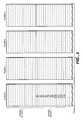
- FIG. 1Ashows a memory system including a memory controller and memory array integrated circuits.
- FIG. 1Bshows a host system that operates with the memory system of FIG. 1A .
- FIG. 2shows an example organization of the memory array of FIG. 1A .
- FIG. 3shows an example host data sector with overhead data as stored in the memory array of FIG. 1A .
- FIG. 4shows a second example organization of the memory array of FIG. 1A ;
- FIG. 5shows a third example organization of the memory array of FIG. 1A ;
- FIG. 6shows an extension of the third example organization of the memory array of FIG. 1A
- FIG. 7shows correspondence between logical units and physical locations for data stored in a memory array such as that of FIG. 1A .
- FIG. 8Ashows correspondence between logical units and physical locations for data stored in a memory array according to an embodiment of the present invention.
- FIG. 8Bshows the operation of an offset in logical-to-physical mapping in the example of FIG. 8A .
- FIG. 9Ashows correspondence between logical units and physical locations for data stored in a memory array according to another embodiment of the present invention.
- FIG. 9Bshows the operation of an offset in logical-to-physical mapping in the example of FIG. 9A .
- FIG. 10shows how a cluster of 8 sectors may be aligned to pages having 4 sectors.
- a flash memoryincludes a memory cell array and a controller.
- two integrated circuit devices (chips) 1 and 13include an array 15 of memory cells and various logic circuits 17 .
- the logic circuits 17interface with a controller 19 on a separate chip through data, command and status circuits, and also provide addressing, data transfer and sensing, and other support to the array 13 .
- a number of memory array chipscan be from one to many, depending upon the storage capacity provided.
- a memory cell arraymay be located on a single chip or may be comprised of memory cells on multiple chips.
- the controller and part or the entire arraycan alternatively be combined onto a single integrated circuit chip but this is currently not an economical alternative.
- a typical controller 19includes a microprocessor 21 , a read-only-memory (ROM) 23 primarily to store firmware and a buffer memory (RAM) 25 primarily for the temporary storage of user data either being written to or read from the memory chips 11 and 13 .
- Buffer memory 25may be either volatile or non-volatile memory.
- Circuits 27interface with the memory array chip(s) and circuits 29 interface with a host though connections 31 .
- connections 31 of the memory of FIG. 1Amate with connections 31 ′ of a host system, an example of which is given in FIG. 1B .
- Data transfers between the host and the memory of FIG. 1Aare through interface circuits 35 .
- a typical hostalso includes a microprocessor 37 , a ROM 39 for storing firmware code and RAM 41 .
- Other circuits and subsystems 43often include a high capacity magnetic data storage disk drive, interface circuits for a keyboard, a monitor and the like, depending upon the particular host system.
- hostsinclude desktop computers, laptop computers, handheld computers, palmtop computers, personal digital assistants (PDAs), MP3 and other audio players, digital cameras, video cameras, electronic game machines, wireless and wired telephony devices, answering machines, voice recorders, network routers and others.
- PDAspersonal digital assistants
- MP3and other audio players
- digital camerasdigital cameras
- video cameraselectronic game machines
- electronic game machineselectronic game machines
- wireless and wired telephony devicesanswering machines
- voice recordersnetwork routers and others.
- the memory of FIG. 1Amay be implemented as a small enclosed card containing the controller and all its memory array circuit devices in a form that is removably connectable with the host of FIG. 1B . That is, mating connections 31 and 31 ′ allow a card to be disconnected and moved to another host, or replaced by connecting another card to the host.
- the memory array devicesmay be enclosed in a separate card that is electrically and mechanically connectable with a card containing the controller and connections 31 .
- the memory of FIG. 1Amay be embedded within the host of FIG. 1B , wherein the connections 31 and 31 ′ are permanently made. In this case, the memory is usually contained within an enclosure of the host along with other components.
- a memory chipsuch as memory chip 11 may connect directly to connections 31 ′ of the host system without a memory controller between them. In this case, the functions of the memory controller are performed by microprocessor 37 of the host system.
- FIG. 2illustrates a portion of a memory array wherein memory cells are grouped into erase blocks, the cells in each erase block being erasable together as part of a single erase operation, usually simultaneously.
- An erase blockis the minimum unit of erase.
- the size of the individual memory cell erase blocks of FIG. 2can vary but one commercially practiced form includes a single sector of data in an individual erase block. The contents of such a data sector are illustrated in FIG. 3 .
- User data 51are typically 512 bytes.
- overhead datathat includes an ECC 53 calculated from the user data, parameters 55 relating to the sector data and/or the erase block in which the sector is programmed and an ECC 57 calculated from the parameters 55 and any other overhead data that might be included.
- a single ECCmay be calculated from both user data 51 and parameters 55 .
- the parameters 55may include a quantity related to the number of program/erase cycles experienced by the erase block, this quantity being updated after each cycle or some number of cycles.
- this experience quantityis used in a wear leveling algorithm, logical block addresses are regularly re-mapped to different physical block addresses in order to even out the usage (wear) of all the erase blocks.
- Another use of the experience quantityis to change voltages and other parameters of programming, reading and/or erasing as a function of the number of cycles experienced by different erase blocks.
- the parameters 55may also include an indication of the bit values assigned to each of the storage states of the memory cells, referred to as their “rotation”. This also has a beneficial effect in wear leveling.
- One or more flagsmay also be included in the parameters 55 that indicate status or states. Indications of voltage levels to be used for programming and/or erasing the erase block can also be stored within the parameters 55 , these voltages being updated as the number of cycles experienced by the erase block and other factors change.
- Other examples of the parameters 55include an identification of any defective cells within the erase block, the logical address of the data that is mapped into this physical block and the address of any substitute erase block in case the primary erase block is defective.
- the particular combination of parameters 55 that are used in any memory systemwill vary in accordance with the design. Also, some or all of the overhead data can be stored in erase blocks dedicated to such a function, rather than in the erase block containing the user data or to which the overhead data pertains.
- An example erase block 59still the minimum unit of erase, contains four pages 0 - 3 , each of which is the minimum unit of programming.
- One or more host sectors of dataare stored in each page, usually along with overhead data including at least the ECC calculated from the sector's data and may be in the form of the data sector of FIG. 3 .
- Re-writing the data of an entire erase blockusually involves programming the new data into an available erase block of an erase block pool, the original erase block then being erased and placed in the erase pool.
- the updated dataare typically stored in a page of an erase block from the erased block pool and data in the remaining unchanged pages are copied from the original erase block into the new erase block.
- the original erase blockis then erased.
- Variations of this large block management techniqueinclude writing the updated data into a page of another erase block without moving data from the original erase block or erasing it. This results in multiple pages having the same logical address.
- the most recent page of datais identified by some convenient technique such as the time of programming that is recorded as a field in sector or page overhead data.
- FIG. 5A further multi-sector erase block arrangement is illustrated in FIG. 5 .
- the total memory cell arrayis physically divided into two or more planes, four planes 0 - 3 being illustrated.
- Each planeis a sub-array of memory cells that has its own data registers, sense amplifiers, addressing decoders and the like in order to be able to operate largely independently of the other planes. All the planes may be provided on a single integrated circuit device or on multiple devices, an example being to form each plane from one or more distinct integrated circuit devices.
- Each erase block in the example system of FIG. 5contains 16 pages P 0 -P 15 , each page having a capacity of one, two or more host data sectors and some overhead data.
- FIG. 6Yet another memory cell arrangement is illustrated in FIG. 6 .
- Each planecontains a large number of erase blocks.
- erase blocks within different planes of a chip, or from different chipsare logically linked to form metablocks.
- One such metablockis illustrated in FIG. 6 .
- Each metablockis logically addressable and the memory controller assigns and keeps track of the erase blocks that form the individual metablocks.
- the host systemprovides data in the form of a stream of sectors. This stream of sectors is divided into logical blocks.
- a logical blockis a logical unit of data that contains the same number of sectors of data as are contained in a metablock of the memory array.
- the memory controllermaintains a record of the location where each logical block is stored.
- Such a logical block 61 of FIG. 6is identified by a logical block addresses (LBA) that is mapped by the controller into the physical block numbers (PBNs) of the blocks that make up the metablock. All blocks of the metablock are erased together, and pages from each block are generally programmed and read simultaneously. A group of pages from different erase blocks of a metablock programmed in parallel may be considered a metapage. This may be considered the unit of programming of a memory system that uses a metablock architecture. Programming of data using large metapages that extend across multiple erase blocks of a metablock provides a high degree of parallelism and thus allows a high rate of data storage.
- LBAlogical block addresses
- PBNsphysical block numbers
- a group of erase blocks forming a metablockmay be treated as a single erase block and may be referred to simply as a block.
- a group of pages extending across the erase blocks of a metablockmay be treated as a single page (or metapage).
- Certain techniques described in this applicationmay be carried out in both architectures that link erase blocks to form metablocks and those that do not link erase blocks to form metablocks.
- blockas used in this application, may refer to either a single erase block, or a group of erase blocks linked to form a metablock.
- the term “page,” as used in this applicationmay refer to either a page of an individual erase block or a metapage that extends across the erase blocks of a metablock.
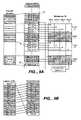
- FIG. 7shows an example of misalignment of clusters stored in a metablock 72 having four sectors per metapage.
- Datais received from a host as a series of clusters, with each cluster comprising 4 sectors.
- Cluster Kextends across two logical blocks. Thus, part of cluster K (sectors X ⁇ 3 to X ⁇ 1) is in a first logical block 74 while part of cluster K (sector X) is in a second logical block 76 . Because sector X is the first sector of the second logical block, it is stored in the first page (page 0 ) of metablock 72 .
- a signalmay be sent to the host when sector X is written, indicating that writing of cluster K is complete. The host may then send cluster K+1.
- the first part of cluster K+1(sectors X+1, X+2 and X+3) is stored in page 0 with sector X. However, because a page stores only 4 sectors of data, sector X+4 must be stored in the next page (page 1 ). Sector X+4 may be stored in a buffer prior to being written to page 1 . Thus, a second page write operation is needed to store cluster K+1. Similarly, subsequent clusters K+2 to K+N/4 each require two write operations because each cluster extends into two pages due to misalignment between clusters and pages. The final cluster of logical block 76 (cluster K+N/4) is partially written to the first page of a third metablock 78 . Thus, the misalignment is continued throughout subsequent metablocks.
- each clusterrequires two write operations in this example, the time to store data may be considerably longer than it would be if each cluster were written in a single write operation.
- This problemmay also exist where a cluster does not contain the same amount of data as a page. For example, if a cluster is smaller than a page then some clusters may be written in a single page while others extend into two pages. If a cluster is larger than a page, some pages may contain only data from one cluster while some contain data from two clusters. Thus, a cluster that is twice as large as a page may require three write operations.
- FIG. 8Ashows an example of alignment of host clusters with pages of metablock 72 according to an embodiment of the present invention.
- a hostsends a series of clusters of data K to K+N/4, in sequential order, for storage in a memory.
- the memoryincludes multiple metablocks where a metablock is made up of multiple erase blocks that may be programmed and erased together.
- a unit of data corresponding to a metablockis a logical block.
- the clusters of data K to K+N/4extend across 3 logical blocks 74 , 76 , 78 .
- sector X of cluster Kis received, it is stored in the first page (page 0 ) of the metablock 72 .
- the location shown for sector Xindicates that it is in the last location in page 0 .
- Cluster K+1is aligned to page 1 so that the boundary between cluster K and cluster K+1 (boundary between sector X and sector X+1) is located at the page boundary between page 0 and page 1 .
- the start of cluster K+1begins at the start of page 1 and the cluster K+1 is considered to be aligned to page 1 .
- the size of a clusteris the same as the size of a page so that cluster K+1 fits page 1 with the end of cluster K+1 also coinciding with the end of page 1 .
- Cluster K+2is likewise aligned to page 2 .
- cluster K+3 to K+N/4 ⁇ 1are aligned to respective pages 3 to N/4 ⁇ 4.
- cluster K+N/4is received from the host.
- Sectors X+N ⁇ 3, X+N ⁇ 2 and X+N ⁇ 1are stored in the first page (page 0 ) of metablock 72 with sector X.
- metablock 72has a first page (page 0 ) that contains a partial cluster from the head of logical block 76 and a partial cluster from the tail of logical block 76 .
- the other pages of the metablockcontain one cluster each so that only one write operation is required for each of these pages. This may allow faster writing of data to the memory array compared with certain prior art systems.
- the offset in this examplemay be calculated from the difference between the current command's first logical address and the logical address of the first sector in the logical block.
- An equation for calculating this offsetis:
- Offset⁇ ( current ⁇ ⁇ command ' ⁇ s first ⁇ ⁇ logical ⁇ ⁇ address ) ⁇ mod ⁇ ( number ⁇ ⁇ of ⁇ ⁇ sectors per ⁇ ⁇ page ) ⁇ - ( number ⁇ ⁇ of ⁇ ⁇ sectors ⁇ ⁇ per ⁇ ⁇ page )
- the first logical sectoris written to the fourth physical address. This may be considered an offset of ⁇ 3 (minus three) in the mapping of this sector, where zero offset is mapping of the first logical sector to the first physical location. This may also be considered an offset of N ⁇ 3 because the sector stored in the first physical location is sector N ⁇ 3. Subsequent sectors are also written with an offset of ⁇ 3 until the end of metablock 72 is reached.
- FIGS. 8A and 8Bshow three sectors (X+N ⁇ 3, X+N ⁇ 2 and X+N ⁇ 1) that are wrapped-around from the end of logical block 76 to be stored at the start of metablock 72 , the number of sectors wrapped-around in this way may be from one to three.
- the size of the offset for a given logical blockmay be from one to one less than the number of sectors in a page.
- Certain memory designsdo not allow multiple writing operations to the same page of a block.
- that pagemay not have additional data written to it because subsequent programming could corrupt the stored data.
- the storage scheme shown in FIG. 8Amight not be possible because after programming sector X, subsequent programming of sectors X+N ⁇ 3, X+N ⁇ 2 and X+N ⁇ 1 in page 0 may not be possible.
- pagesmay only be written in sequential order. For example, page 0 is written first, then page 1 , page 2 etc. After page 1 is written page 0 may not be written because this is not sequential. In such designs, writing of any data in page 0 , after writing pages 1 to page N/4 ⁇ 1 may not be possible.
- FIG. 9Ashows another embodiment of the present invention that uses a scratch pad block 91 to implement an alignment scheme to align clusters and pages.
- a scratch pad blockis described in US patent application entitled “Scratch pad block,” having an attorney docket number SNDK.406US0, filed on the same day as the present application, which patent application is hereby incorporated by reference in its entirety.
- a series of clusters of host data(clusters K to K+N/4) are received from a host for storage in a memory array.
- Cluster Kincludes sectors X+3 to X+1 from a first logical block 74 and sector X from a second logical block 76 .
- Sectors X+3 to X+1are stored in a metablock (not shown) associated with the first logical block 74 .
- Sector Xis not immediately stored in metablock 72 when it is received. Instead, sector X is stored at another location. In this example, the location is in a scratch pad block 91 .
- Thisis a block of the memory array that is used for short-term storage of various data in non-volatile memory. Because sector X is stored in non-volatile memory, it will not be lost if power is removed from the memory system. Alternatively, sector X may be stored in some other non-volatile memory or, if permitted, in a volatile memory. After sector X is stored in scratch pad block 91 , cluster K+1 is received.
- Cluster K+1is stored in page 0 and is aligned to page 0 .
- the boundary between cluster K and cluster K+1coincides with the starting boundary of page 0 .
- cluster K+1fits page 0 exactly and the end of cluster K+1 coincides with the end of page 0 .
- subsequent clusters K+2 to K+N/4+1are written one to a page.
- cluster K+N/4is received, the three sectors from cluster K+N/4 that are from logical block 76 (sectors X+N ⁇ 3, X+N ⁇ 2 and X+N ⁇ 1) are written in page N/4+1 along with sector X, which is copied from scratch pad block 91 .
- the last page in metablock 72contains a cluster fragment from the head of logical block 76 and a cluster fragment from the tail of logical block 76 .
- sector Xcould be written to page N/4 ⁇ 1 when it is received without being stored at another location.
- the offset for alignmentmay be from one to three sectors in this example. Generally, the offset may be from zero (if clusters are received with boundary locations that coincide with logical block boundaries) to a maximum of one less than the number of sectors per page.
- the first logical sectoris written to the last physical address. This may be considered an offset of 1 (one) in the mapping of this sector, where the addresses of the metablock wrap-around (the first address of logical block 76 is considered sequential to the last address of logical block 76 ). All other sectors are also written with an offset of one.
- the second sector received, sector X+1goes to the first physical address etc.
- the data stored in metablock 72may be found using the offset for logical block 76 and no sector-by-sector indexing of data is required. Storage of data in metablocks using an offset (or page-tag) of this kind is further described in patent application Ser. No. 10/750,155.
- FIGS. 8 and 9show clusters and pages having four sectors each.
- a clustermay extend over multiple pages and still be aligned to the pages.
- a cluster of 8 sectorsmay be aligned to pages having 4 sectors as shown in FIG. 10 .
- the clusters of FIG. 10fully occupy 2 pages of metablock 72 , where they could extend across 3 pages if they were not aligned.
- alignmentmay improve efficiency by reducing the number of writes per cluster from 3 to 2.
- every cluster boundarycoincides with a page boundary, although not every page boundary coincides with a cluster boundary.
- Clustersmay be smaller than a page and still be aligned to the page. For example, a cluster may contain 16 sectors and a page may contain 64 sectors. Without alignment, some clusters may extend across two pages and require two write operations. With alignment, these clusters are written to a single page thus improving efficiency. In this example, every page boundary coincides with a cluster boundary, although not every cluster boundary coincides with a page boundary.
- An offset for a logical blockmay be derived from the difference between the starting address of the data being written and the starting address of a logical block.
- the start of a logical blockwill be the start of a page and the host begins writing data at the start of a cluster.
- the offsetmay be calculated from the remainder when this difference is divided by the number of sectors per page. If the remainder is zero (the difference is an integer number of pages), then the boundaries may be considered aligned.
- One way to store the offset of a logical blockis to record the logical address of the sector stored in the first physical address of the logical block.
- An offsetmay be derived from the logical address of the first sector of host data stored in the memory.
- the first portion of logical address spaceis dedicated to system information such as a boot sector, one or more File Allocation Tables (FATs), root directory and subdirectories.
- FATsFile Allocation Tables
- Host datais stored immediately after the system information so that the first cluster begins after the end of the system information.
- the logical address range of the system informationmay be found from the boot sector, which records the locations of the FAT (or FATs) and directories.
- the boot sectoralso indicates the number of sectors per cluster so that all cluster boundary locations may be obtained from the boot sector.
- a memory arraymay be partitioned into two or more partitions that may operate separately in some respects.
- An individual partition of the arraymay have a dedicated portion of logical address space for system information for that partition.
- a different offsetmay be derived for different partitions according to the location of the first sector of host data stored in the partition.
- different partitions within the same memory arraymay operate with different offsets so that each partition stores data with clusters aligned to pages.
- the logical block address formatmay include the offset (page tag) of the logical block.
- the physical location of a sector in a metablockmay be determined without a prior block read.
- the principles described abovemay be applied to a unit of a logical group instead of applying to a unit of a logical block.
- an offsetis calculated for a logical group and not a logical block.
- a logical groupis a unit of data that holds data equal to the data in one erase block of the memory array.
- a logical blockcontains an integer number of logical groups.
- an offsetmay be derived for each logical group.
- the logical group address formatmay include the offset for that logical group and different logical groups may have different offsets.
- an offsetmay be maintained for units that have less data than in a block. For example, a unit that contains half, quarter, or some other fraction of the data of a block may be used, with a different offset derived for each unit. Thus, data may be aligned in units of different sizes.
- an offsetallows received data to be rapidly written without first copying sectors of data.
- Such offsetsmay be combined with offsets calculated according to the present invention to obtain a final offset value that is used for the storage of data. For example, where data is received that has a logical address in the middle of the logical address range of a logical block, the data may be written to the beginning of the metablock according to a first offset. However, an additional offset may align the data to the page boundaries so that the final offset is comprised of two components.
Landscapes
- Engineering & Computer Science (AREA)
- Theoretical Computer Science (AREA)
- Physics & Mathematics (AREA)
- General Engineering & Computer Science (AREA)
- General Physics & Mathematics (AREA)
- Human Computer Interaction (AREA)
- Read Only Memory (AREA)
- Techniques For Improving Reliability Of Storages (AREA)
Abstract
Description
Thus, for the example of
Offset={(X−3) mod (4)}−4=1−4=−3
Offset=(Current command's first logical address) mod (number of sectors per page)
Thus, in
The offset for alignment may be from one to three sectors in this example. Generally, the offset may be from zero (if clusters are received with boundary locations that coincide with logical block boundaries) to a maximum of one less than the number of sectors per page.
Claims (23)
Priority Applications (7)
| Application Number | Priority Date | Filing Date | Title |
|---|---|---|---|
| US11/015,211US7395404B2 (en) | 2004-12-16 | 2004-12-16 | Cluster auto-alignment for storing addressable data packets in a non-volatile memory array |
| JP2007546717AJP4960882B2 (en) | 2004-12-16 | 2005-11-30 | Automatic cluster alignment |
| KR1020077012085AKR20070102485A (en) | 2004-12-16 | 2005-11-30 | Cluster auto-alignment |
| CN2005800422572ACN101099125B (en) | 2004-12-16 | 2005-11-30 | Automatic alignment method and memory system for clusters |
| EP05852506AEP1828881B1 (en) | 2004-12-16 | 2005-11-30 | Cluster auto-alignment |
| PCT/US2005/043285WO2006065536A1 (en) | 2004-12-16 | 2005-11-30 | Cluster auto-alignment |
| TW094144090ATWI386801B (en) | 2004-12-16 | 2005-12-13 | Cluster auto-alignment |
Applications Claiming Priority (1)
| Application Number | Priority Date | Filing Date | Title |
|---|---|---|---|
| US11/015,211US7395404B2 (en) | 2004-12-16 | 2004-12-16 | Cluster auto-alignment for storing addressable data packets in a non-volatile memory array |
Publications (2)
| Publication Number | Publication Date |
|---|---|
| US20060136655A1 US20060136655A1 (en) | 2006-06-22 |
| US7395404B2true US7395404B2 (en) | 2008-07-01 |
Family
ID=36123113
Family Applications (1)
| Application Number | Title | Priority Date | Filing Date |
|---|---|---|---|
| US11/015,211Expired - LifetimeUS7395404B2 (en) | 2004-12-16 | 2004-12-16 | Cluster auto-alignment for storing addressable data packets in a non-volatile memory array |
Country Status (7)
| Country | Link |
|---|---|
| US (1) | US7395404B2 (en) |
| EP (1) | EP1828881B1 (en) |
| JP (1) | JP4960882B2 (en) |
| KR (1) | KR20070102485A (en) |
| CN (1) | CN101099125B (en) |
| TW (1) | TWI386801B (en) |
| WO (1) | WO2006065536A1 (en) |
Cited By (66)
| Publication number | Priority date | Publication date | Assignee | Title |
|---|---|---|---|---|
| US20080184086A1 (en)* | 2007-01-29 | 2008-07-31 | Sun Kwon Kim | Semiconductor memory system performing data error correction using flag cell array of buffer memory |
| US20100037102A1 (en)* | 2008-08-08 | 2010-02-11 | Seagate Technology Llc | Fault-tolerant non-volatile buddy memory structure |
| US20100095057A1 (en)* | 2008-10-15 | 2010-04-15 | Seagate Technology Llc | Non-volatile resistive sense memory on-chip cache |
| US20100118587A1 (en)* | 2008-11-12 | 2010-05-13 | Seagate Technology Llc | Resistive sense memory array with partial block update capability |
| US20100228912A1 (en)* | 2009-03-04 | 2010-09-09 | Seagate Technology Llc | Non-Volatile Memory With Hybrid Index Tag Array |
| US20120066441A1 (en)* | 2009-10-15 | 2012-03-15 | Densbits Technologies Ltd. | Systems and methods for averaging error rates in non-volatile devices and storage systems |
| US8724387B2 (en) | 2009-10-22 | 2014-05-13 | Densbits Technologies Ltd. | Method, system, and computer readable medium for reading and programming flash memory cells using multiple bias voltages |
| US8745317B2 (en) | 2010-04-07 | 2014-06-03 | Densbits Technologies Ltd. | System and method for storing information in a multi-level cell memory |
| US8751726B2 (en) | 2007-12-05 | 2014-06-10 | Densbits Technologies Ltd. | System and methods employing mock thresholds to generate actual reading thresholds in flash memory devices |
| US8762800B1 (en) | 2008-01-31 | 2014-06-24 | Densbits Technologies Ltd. | Systems and methods for handling immediate data errors in flash memory |
| US20140189234A1 (en)* | 2010-12-13 | 2014-07-03 | Seagate Technology Llc | Protecting volatile data of a storage device in response to a state reset |
| US8782500B2 (en) | 2007-12-12 | 2014-07-15 | Densbits Technologies Ltd. | Systems and methods for error correction and decoding on multi-level physical media |
| US8799563B2 (en) | 2007-10-22 | 2014-08-05 | Densbits Technologies Ltd. | Methods for adaptively programming flash memory devices and flash memory systems incorporating same |
| US8819385B2 (en) | 2009-04-06 | 2014-08-26 | Densbits Technologies Ltd. | Device and method for managing a flash memory |
| US8838937B1 (en) | 2012-05-23 | 2014-09-16 | Densbits Technologies Ltd. | Methods, systems and computer readable medium for writing and reading data |
| US8850296B2 (en) | 2009-04-06 | 2014-09-30 | Densbits Technologies Ltd. | Encoding method and system, decoding method and system |
| US8850297B1 (en) | 2010-07-01 | 2014-09-30 | Densbits Technologies Ltd. | System and method for multi-dimensional encoding and decoding |
| US8850100B2 (en) | 2010-12-07 | 2014-09-30 | Densbits Technologies Ltd. | Interleaving codeword portions between multiple planes and/or dies of a flash memory device |
| US8879325B1 (en) | 2012-05-30 | 2014-11-04 | Densbits Technologies Ltd. | System, method and computer program product for processing read threshold information and for reading a flash memory module |
| US8924631B2 (en)* | 2011-09-15 | 2014-12-30 | Sandisk Technologies Inc. | Method and system for random write unalignment handling |
| US8947941B2 (en) | 2012-02-09 | 2015-02-03 | Densbits Technologies Ltd. | State responsive operations relating to flash memory cells |
| US8964464B2 (en) | 2010-08-24 | 2015-02-24 | Densbits Technologies Ltd. | System and method for accelerated sampling |
| US8972472B2 (en) | 2008-03-25 | 2015-03-03 | Densbits Technologies Ltd. | Apparatus and methods for hardware-efficient unbiased rounding |
| US8990665B1 (en) | 2011-04-06 | 2015-03-24 | Densbits Technologies Ltd. | System, method and computer program product for joint search of a read threshold and soft decoding |
| US8996790B1 (en) | 2011-05-12 | 2015-03-31 | Densbits Technologies Ltd. | System and method for flash memory management |
| US8995197B1 (en) | 2009-08-26 | 2015-03-31 | Densbits Technologies Ltd. | System and methods for dynamic erase and program control for flash memory device memories |
| US8996839B1 (en) | 2012-01-23 | 2015-03-31 | Western Digital Technologies, Inc. | Data storage device aligning partition to boundary of sector when partition offset correlates with offset of write commands |
| US8996793B1 (en) | 2012-04-24 | 2015-03-31 | Densbits Technologies Ltd. | System, method and computer readable medium for generating soft information |
| US8996788B2 (en) | 2012-02-09 | 2015-03-31 | Densbits Technologies Ltd. | Configurable flash interface |
| US9037777B2 (en) | 2009-12-22 | 2015-05-19 | Densbits Technologies Ltd. | Device, system, and method for reducing program/read disturb in flash arrays |
| US9063878B2 (en) | 2010-11-03 | 2015-06-23 | Densbits Technologies Ltd. | Method, system and computer readable medium for copy back |
| US9063838B1 (en)* | 2012-01-23 | 2015-06-23 | Western Digital Technologies, Inc. | Data storage device shifting data chunks of alignment zone relative to sector boundaries |
| US9069659B1 (en) | 2013-01-03 | 2015-06-30 | Densbits Technologies Ltd. | Read threshold determination using reference read threshold |
| US9110785B1 (en) | 2011-05-12 | 2015-08-18 | Densbits Technologies Ltd. | Ordered merge of data sectors that belong to memory space portions |
| US9116795B2 (en) | 2012-01-18 | 2015-08-25 | Samsung Electronics Co., Ltd. | Non-volatile memory devices using a mapping manager |
| US9136876B1 (en) | 2013-06-13 | 2015-09-15 | Densbits Technologies Ltd. | Size limited multi-dimensional decoding |
| US9195592B1 (en) | 2011-05-12 | 2015-11-24 | Densbits Technologies Ltd. | Advanced management of a non-volatile memory |
| US9330767B1 (en) | 2009-08-26 | 2016-05-03 | Avago Technologies General Ip (Singapore) Pte. Ltd. | Flash memory module and method for programming a page of flash memory cells |
| US9348694B1 (en) | 2013-10-09 | 2016-05-24 | Avago Technologies General Ip (Singapore) Pte. Ltd. | Detecting and managing bad columns |
| US9368225B1 (en) | 2012-11-21 | 2016-06-14 | Avago Technologies General Ip (Singapore) Pte. Ltd. | Determining read thresholds based upon read error direction statistics |
| US9372792B1 (en) | 2011-05-12 | 2016-06-21 | Avago Technologies General Ip (Singapore) Pte. Ltd. | Advanced management of a non-volatile memory |
| US9397706B1 (en) | 2013-10-09 | 2016-07-19 | Avago Technologies General Ip (Singapore) Pte. Ltd. | System and method for irregular multiple dimension decoding and encoding |
| US9396106B2 (en) | 2011-05-12 | 2016-07-19 | Avago Technologies General Ip (Singapore) Pte. Ltd. | Advanced management of a non-volatile memory |
| US9407291B1 (en) | 2014-07-03 | 2016-08-02 | Avago Technologies General Ip (Singapore) Pte. Ltd. | Parallel encoding method and system |
| US9413491B1 (en) | 2013-10-08 | 2016-08-09 | Avago Technologies General Ip (Singapore) Pte. Ltd. | System and method for multiple dimension decoding and encoding a message |
| US9449702B1 (en) | 2014-07-08 | 2016-09-20 | Avago Technologies General Ip (Singapore) Pte. Ltd. | Power management |
| US9501392B1 (en) | 2011-05-12 | 2016-11-22 | Avago Technologies General Ip (Singapore) Pte. Ltd. | Management of a non-volatile memory module |
| US9524211B1 (en) | 2014-11-18 | 2016-12-20 | Avago Technologies General Ip (Singapore) Pte. Ltd. | Codeword management |
| US9536612B1 (en) | 2014-01-23 | 2017-01-03 | Avago Technologies General Ip (Singapore) Pte. Ltd | Digital signaling processing for three dimensional flash memory arrays |
| US9542262B1 (en) | 2014-05-29 | 2017-01-10 | Avago Technologies General Ip (Singapore) Pte. Ltd. | Error correction |
| US9554073B2 (en) | 2013-09-17 | 2017-01-24 | Samsung Electronics Co., Ltd. | Integrated circuit and image sensor comprising same |
| US9786388B1 (en) | 2013-10-09 | 2017-10-10 | Avago Technologies General Ip (Singapore) Pte. Ltd. | Detecting and managing bad columns |
| US9851921B1 (en) | 2015-07-05 | 2017-12-26 | Avago Technologies General Ip (Singapore) Pte. Ltd. | Flash memory chip processing |
| US9875053B2 (en) | 2015-06-05 | 2018-01-23 | Western Digital Technologies, Inc. | Scheduling scheme(s) for a multi-die storage device |
| US9892033B1 (en) | 2014-06-24 | 2018-02-13 | Avago Technologies General Ip (Singapore) Pte. Ltd. | Management of memory units |
| US9921774B2 (en) | 2010-12-13 | 2018-03-20 | Seagate Technology Llc | Data storage management in a memory device |
| US9921954B1 (en) | 2012-08-27 | 2018-03-20 | Avago Technologies General Ip (Singapore) Pte. Ltd. | Method and system for split flash memory management between host and storage controller |
| US9954558B1 (en) | 2016-03-03 | 2018-04-24 | Avago Technologies General Ip (Singapore) Pte. Ltd. | Fast decoding of data stored in a flash memory |
| US9972393B1 (en) | 2014-07-03 | 2018-05-15 | Avago Technologies General Ip (Singapore) Pte. Ltd. | Accelerating programming of a flash memory module |
| US10120792B1 (en) | 2014-01-29 | 2018-11-06 | Avago Technologies General Ip (Singapore) Pte. Ltd. | Programming an embedded flash storage device |
| US10289327B2 (en) | 2015-06-05 | 2019-05-14 | Western Digital Technologies, Inc. | Scheduling scheme(s) for a multi-die storage device |
| US10289561B2 (en) | 2017-08-08 | 2019-05-14 | Samsung Electronics Co., Ltd. | Nonvolatile memory devices and methods of controlling the same |
| US10305515B1 (en) | 2015-02-02 | 2019-05-28 | Avago Technologies International Sales Pte. Limited | System and method for encoding using multiple linear feedback shift registers |
| US10372603B2 (en) | 2017-11-27 | 2019-08-06 | Western Digital Technologies, Inc. | Handling of unaligned writes |
| US10628255B1 (en) | 2015-06-11 | 2020-04-21 | Avago Technologies International Sales Pte. Limited | Multi-dimensional decoding |
| US12362008B2 (en) | 2023-09-25 | 2025-07-15 | Kneron Inc. | Compute-In-Memory architecture using look-up tables |
Families Citing this family (63)
| Publication number | Priority date | Publication date | Assignee | Title |
|---|---|---|---|---|
| US7173852B2 (en)* | 2003-10-03 | 2007-02-06 | Sandisk Corporation | Corrected data storage and handling methods |
| US7315916B2 (en) | 2004-12-16 | 2008-01-01 | Sandisk Corporation | Scratch pad block |
| JP4863749B2 (en) | 2006-03-29 | 2012-01-25 | 株式会社日立製作所 | Storage device using flash memory, erase number leveling method thereof, and erase number level program |
| KR100758301B1 (en)* | 2006-08-04 | 2007-09-12 | 삼성전자주식회사 | Memory card and its data storage method |
| US20080235480A1 (en)* | 2007-03-21 | 2008-09-25 | Shai Traister | Systems for storing memory operations in a queue |
| US7987332B2 (en)* | 2007-03-21 | 2011-07-26 | Sandisk Technologies Inc. | Methods for storing memory operations in a queue |
| US8504784B2 (en)* | 2007-06-27 | 2013-08-06 | Sandisk Technologies Inc. | Scheduling methods of phased garbage collection and housekeeping operations in a flash memory system |
| US7818493B2 (en)* | 2007-09-07 | 2010-10-19 | Sandisk Corporation | Adaptive block list management |
| US8762620B2 (en)* | 2007-12-27 | 2014-06-24 | Sandisk Enterprise Ip Llc | Multiprocessor storage controller |
| KR101465789B1 (en)* | 2008-01-24 | 2014-11-26 | 삼성전자주식회사 | Write and merge methods in memory card systems for reducing the number of page copies |
| TWI390548B (en)* | 2008-07-03 | 2013-03-21 | Silicon Motion Inc | Data storing methods and apparatus thereof |
| JP5338260B2 (en)* | 2008-10-31 | 2013-11-13 | アイシン・エィ・ダブリュ株式会社 | Data list read / write device and method |
| US8392687B2 (en) | 2009-01-21 | 2013-03-05 | Micron Technology, Inc. | Solid state memory formatting |
| US8782325B1 (en)* | 2009-02-09 | 2014-07-15 | Marvell International Ltd. | Data type based alignment of data written to non-volatile memory |
| KR101615659B1 (en) | 2009-07-16 | 2016-05-12 | 삼성전자주식회사 | Apparatus and method for scratch pad memory management |
| US8612718B2 (en)* | 2009-08-19 | 2013-12-17 | Seagate Technology Llc | Mapping alignment |
| CN102243611B (en)* | 2010-05-11 | 2015-06-17 | 深圳市朗科科技股份有限公司 | Data storage method and system |
| JP2012173778A (en)* | 2011-02-17 | 2012-09-10 | Sony Corp | Management device and management method |
| US8909894B1 (en)* | 2011-03-16 | 2014-12-09 | Tintri Inc. | Automatically aligning virtual blocks to physical blocks |
| TWI479315B (en)* | 2012-07-03 | 2015-04-01 | Phison Electronics Corp | Memory storage device, memory controller thereof, and method for programming data thereof |
| CN103544118B (en)* | 2012-07-17 | 2016-09-14 | 群联电子股份有限公司 | Memory storage device, its memory controller and data writing method |
| US9699263B1 (en) | 2012-08-17 | 2017-07-04 | Sandisk Technologies Llc. | Automatic read and write acceleration of data accessed by virtual machines |
| CN102929790A (en)* | 2012-10-15 | 2013-02-13 | 株洲南车时代电气股份有限公司 | Data storage system and method |
| US9612948B2 (en) | 2012-12-27 | 2017-04-04 | Sandisk Technologies Llc | Reads and writes between a contiguous data block and noncontiguous sets of logical address blocks in a persistent storage device |
| US9454420B1 (en) | 2012-12-31 | 2016-09-27 | Sandisk Technologies Llc | Method and system of reading threshold voltage equalization |
| US9870830B1 (en) | 2013-03-14 | 2018-01-16 | Sandisk Technologies Llc | Optimal multilevel sensing for reading data from a storage medium |
| US9524235B1 (en) | 2013-07-25 | 2016-12-20 | Sandisk Technologies Llc | Local hash value generation in non-volatile data storage systems |
| TWI514141B (en)* | 2013-08-08 | 2015-12-21 | Phison Electronics Corp | Memory address management method, memory controller and memory storage device |
| CN104375945B (en)* | 2013-08-15 | 2018-03-13 | 群联电子股份有限公司 | Memory address management method, memory controller and memory storage device |
| US9639463B1 (en) | 2013-08-26 | 2017-05-02 | Sandisk Technologies Llc | Heuristic aware garbage collection scheme in storage systems |
| US9442662B2 (en) | 2013-10-18 | 2016-09-13 | Sandisk Technologies Llc | Device and method for managing die groups |
| US9436831B2 (en) | 2013-10-30 | 2016-09-06 | Sandisk Technologies Llc | Secure erase in a memory device |
| US9703816B2 (en) | 2013-11-19 | 2017-07-11 | Sandisk Technologies Llc | Method and system for forward reference logging in a persistent datastore |
| US9520197B2 (en) | 2013-11-22 | 2016-12-13 | Sandisk Technologies Llc | Adaptive erase of a storage device |
| US9520162B2 (en) | 2013-11-27 | 2016-12-13 | Sandisk Technologies Llc | DIMM device controller supervisor |
| US9582058B2 (en) | 2013-11-29 | 2017-02-28 | Sandisk Technologies Llc | Power inrush management of storage devices |
| US9703636B2 (en) | 2014-03-01 | 2017-07-11 | Sandisk Technologies Llc | Firmware reversion trigger and control |
| US9448876B2 (en) | 2014-03-19 | 2016-09-20 | Sandisk Technologies Llc | Fault detection and prediction in storage devices |
| US9454448B2 (en) | 2014-03-19 | 2016-09-27 | Sandisk Technologies Llc | Fault testing in storage devices |
| US9626399B2 (en) | 2014-03-31 | 2017-04-18 | Sandisk Technologies Llc | Conditional updates for reducing frequency of data modification operations |
| US9626400B2 (en) | 2014-03-31 | 2017-04-18 | Sandisk Technologies Llc | Compaction of information in tiered data structure |
| US9697267B2 (en) | 2014-04-03 | 2017-07-04 | Sandisk Technologies Llc | Methods and systems for performing efficient snapshots in tiered data structures |
| US20150339223A1 (en)* | 2014-05-22 | 2015-11-26 | Kabushiki Kaisha Toshiba | Memory system and method |
| US10372613B2 (en) | 2014-05-30 | 2019-08-06 | Sandisk Technologies Llc | Using sub-region I/O history to cache repeatedly accessed sub-regions in a non-volatile storage device |
| US10146448B2 (en) | 2014-05-30 | 2018-12-04 | Sandisk Technologies Llc | Using history of I/O sequences to trigger cached read ahead in a non-volatile storage device |
| US10656842B2 (en) | 2014-05-30 | 2020-05-19 | Sandisk Technologies Llc | Using history of I/O sizes and I/O sequences to trigger coalesced writes in a non-volatile storage device |
| US10162748B2 (en) | 2014-05-30 | 2018-12-25 | Sandisk Technologies Llc | Prioritizing garbage collection and block allocation based on I/O history for logical address regions |
| US10114557B2 (en) | 2014-05-30 | 2018-10-30 | Sandisk Technologies Llc | Identification of hot regions to enhance performance and endurance of a non-volatile storage device |
| US9703491B2 (en) | 2014-05-30 | 2017-07-11 | Sandisk Technologies Llc | Using history of unaligned writes to cache data and avoid read-modify-writes in a non-volatile storage device |
| US10656840B2 (en) | 2014-05-30 | 2020-05-19 | Sandisk Technologies Llc | Real-time I/O pattern recognition to enhance performance and endurance of a storage device |
| US9652381B2 (en) | 2014-06-19 | 2017-05-16 | Sandisk Technologies Llc | Sub-block garbage collection |
| US9443601B2 (en) | 2014-09-08 | 2016-09-13 | Sandisk Technologies Llc | Holdup capacitor energy harvesting |
| US10565101B2 (en) | 2016-01-29 | 2020-02-18 | Hewlett Packard Enterprise Development Lp | Storing data in a storage device |
| TWI612421B (en)* | 2017-01-20 | 2018-01-21 | 宇瞻科技股份有限公司 | Method of dynamically arranging data for flash memory |
| CN108334276B (en)* | 2017-01-20 | 2021-01-29 | 宇瞻科技股份有限公司 | Dynamic data alignment method of flash memory |
| KR20190061942A (en)* | 2017-11-28 | 2019-06-05 | 에스케이하이닉스 주식회사 | Data storage device and operating method thereof |
| CN107704208B (en)* | 2017-10-13 | 2021-08-10 | 郑州云海信息技术有限公司 | Method, device and medium for repairing metadata |
| US10977182B2 (en)* | 2017-12-01 | 2021-04-13 | Micron Technology, Inc. | Logical block mapping based on an offset |
| CN109388677B (en)* | 2018-08-23 | 2022-10-11 | 顺丰科技有限公司 | Method, device and equipment for synchronizing data among clusters and storage medium thereof |
| US10713163B2 (en) | 2018-09-11 | 2020-07-14 | Toshiba Memory Corporation | Set aware system data and mapping tables |
| US10909030B2 (en)* | 2018-09-11 | 2021-02-02 | Toshiba Memory Corporation | Enhanced trim command support for solid state drives |
| US20240152329A1 (en)* | 2022-11-01 | 2024-05-09 | Kneron Inc. | K-cluster residue number system for edge ai computing |
| CN119166037A (en)* | 2023-10-23 | 2024-12-20 | 百代(上海)数据技术有限公司 | Ways to improve storage performance |
Citations (120)
| Publication number | Priority date | Publication date | Assignee | Title |
|---|---|---|---|---|
| US4139911A (en) | 1978-03-13 | 1979-02-13 | Westinghouse Electric Corp. | High speed sense circuit for semiconductor memories |
| US4218764A (en) | 1978-10-03 | 1980-08-19 | Matsushita Electric Industrial Co., Ltd. | Non-volatile memory refresh control circuit |
| US4253059A (en) | 1979-05-14 | 1981-02-24 | Fairchild Camera & Instrument Corp. | EPROM Reliability test circuit |
| US4460982A (en) | 1982-05-20 | 1984-07-17 | Intel Corporation | Intelligent electrically programmable and electrically erasable ROM |
| US4612630A (en) | 1984-07-27 | 1986-09-16 | Harris Corporation | EEPROM margin testing design |
| US4694454A (en) | 1984-07-27 | 1987-09-15 | Hitachi, Ltd. | Dynamic memory diagnosis and error correction apparatus |
| US4703453A (en) | 1982-02-15 | 1987-10-27 | Hitachi, Ltd. | Semiconductor memory with an improved dummy cell arrangement and with a built-in error correcting code circuit |
| US4703196A (en) | 1984-08-13 | 1987-10-27 | Fujitsu Limited | High voltage precharging circuit |
| US4733394A (en) | 1985-04-23 | 1988-03-22 | Deutsche Itt Industries Gmbh | Electrically programmable semiconductor memory showing redundance |
| US4763305A (en) | 1985-11-27 | 1988-08-09 | Motorola, Inc. | Intelligent write in an EEPROM with data and erase check |
| US4779272A (en) | 1985-11-13 | 1988-10-18 | Mitsubishi Denki Kabushiki Kaisha | Testable variable-threshold non-volatile semiconductor memory |
| US4799195A (en) | 1985-01-26 | 1989-01-17 | Kabushiki Kaisha Toshiba | Semiconductor memory device with a sense amplifier |
| US4809231A (en) | 1987-11-12 | 1989-02-28 | Motorola, Inc. | Method and apparatus for post-packaging testing of one-time programmable memories |
| US4827450A (en) | 1987-07-21 | 1989-05-02 | Sgs-Thomson Microelectronics S.A. | Integrated circuit with memory comprising a fraud-prevention device |
| US4937787A (en) | 1987-06-30 | 1990-06-26 | Nec Corporation | Programmable read only memory with means for discharging bit line before program verifying operation |
| US4962322A (en) | 1988-12-05 | 1990-10-09 | Texas Instruments Incorporated | Nonvolatible capacitor random access memory |
| US4964079A (en) | 1988-04-26 | 1990-10-16 | Sgs-Thomson Microelectronics | Electrically programmable memory with several information bits per cell |
| WO1990012400A1 (en) | 1989-04-13 | 1990-10-18 | Sundisk Corporation | Multi-state eeprom read and write circuits and techniques |
| US5043940A (en) | 1988-06-08 | 1991-08-27 | Eliyahou Harari | Flash EEPROM memory systems having multistate storage cells |
| US5065364A (en) | 1989-09-15 | 1991-11-12 | Intel Corporation | Apparatus for providing block erasing in a flash EPROM |
| US5070032A (en) | 1989-03-15 | 1991-12-03 | Sundisk Corporation | Method of making dense flash eeprom semiconductor memory structures |
| US5095344A (en) | 1988-06-08 | 1992-03-10 | Eliyahou Harari | Highly compact eprom and flash eeprom devices |
| US5119330A (en) | 1989-03-31 | 1992-06-02 | Oki Electric Industry Co, Ltd. | Nonvolatile memory system for multiple value storing |
| US5122985A (en) | 1990-04-16 | 1992-06-16 | Giovani Santin | Circuit and method for erasing eeprom memory arrays to prevent over-erased cells |
| US5132935A (en) | 1990-04-16 | 1992-07-21 | Ashmore Jr Benjamin H | Erasure of eeprom memory arrays to prevent over-erased cells |
| US5151906A (en) | 1989-05-25 | 1992-09-29 | Rohm Co., Ltd. | Semiconductor memory device having self-correcting function |
| US5157629A (en) | 1985-11-22 | 1992-10-20 | Hitachi, Ltd. | Selective application of voltages for testing storage cells in semiconductor memory arrangements |
| US5200959A (en) | 1989-10-17 | 1993-04-06 | Sundisk Corporation | Device and method for defect handling in semi-conductor memory |
| US5200922A (en) | 1990-10-24 | 1993-04-06 | Rao Kameswara K | Redundancy circuit for high speed EPROM and flash memory devices |
| US5239505A (en) | 1990-12-28 | 1993-08-24 | Intel Corporation | Floating gate non-volatile memory with blocks and memory refresh |
| US5262984A (en) | 1988-07-29 | 1993-11-16 | Mitsubishi Denki Kabushiki Kaisha | Non-volatile memory device capable of storing multi-state data |
| US5263032A (en) | 1991-06-27 | 1993-11-16 | Digital Equipment Corporation | Computer system operation with corrected read data function |
| US5270551A (en) | 1990-02-14 | 1993-12-14 | Hitachi, Ltd. | Method of and apparatus for protecting electronic circuit against radiation |
| US5270979A (en) | 1991-03-15 | 1993-12-14 | Sundisk Corporation | Method for optimum erasing of EEPROM |
| US5278794A (en) | 1991-10-14 | 1994-01-11 | Kabushiki Kaisha Toshiba | NAND-cell type electrically erasable and programmable read-only memory with redundancy circuit |
| US5313421A (en) | 1992-01-14 | 1994-05-17 | Sundisk Corporation | EEPROM with split gate source side injection |
| US5313427A (en) | 1991-09-20 | 1994-05-17 | Texas Instruments Incorporated | EEPROM array with narrow margin of voltage thresholds after erase |
| US5315541A (en) | 1992-07-24 | 1994-05-24 | Sundisk Corporation | Segmented column memory array |
| US5321655A (en) | 1989-06-12 | 1994-06-14 | Kabushiki Kaisha Toshiba | Semiconductor memory device |
| US5327383A (en) | 1992-04-21 | 1994-07-05 | Intel Corporation | Method and circuitry for erasing a nonvolatile semiconductor memory incorporating row redundancy |
| US5335198A (en) | 1993-05-06 | 1994-08-02 | Advanced Micro Devices, Inc. | Flash EEPROM array with high endurance |
| US5341334A (en) | 1992-09-02 | 1994-08-23 | Kabushiki Kaisha Toshiba | Level shifter circuit constituted of E and I type transistors and an EEPROM using the same |
| US5343063A (en) | 1990-12-18 | 1994-08-30 | Sundisk Corporation | Dense vertical programmable read only memory cell structure and processes for making them |
| US5347489A (en) | 1992-04-21 | 1994-09-13 | Intel Corporation | Method and circuitry for preconditioning shorted rows in a nonvolatile semiconductor memory incorporating row redundancy |
| US5365486A (en) | 1992-12-16 | 1994-11-15 | Texas Instruments Incorporated | Method and circuitry for refreshing a flash electrically erasable, programmable read only memory |
| US5394359A (en) | 1989-07-20 | 1995-02-28 | Gemplus Card International | MOS integrated circuit with adjustable threshold voltage |
| US5404485A (en) | 1993-03-08 | 1995-04-04 | M-Systems Flash Disk Pioneers Ltd. | Flash file system |
| US5465236A (en) | 1992-06-19 | 1995-11-07 | Kabushiki Kaisha Toshiba | Nonvolatile semiconductor memory system with a plurality of erase blocks |
| GB2289779A (en) | 1994-05-24 | 1995-11-29 | Intel Corp | Automatically scrubbing ECC errors in memory via hardware |
| US5475693A (en) | 1994-12-27 | 1995-12-12 | Intel Corporation | Error management processes for flash EEPROM memory arrays |
| US5504760A (en) | 1991-03-15 | 1996-04-02 | Sandisk Corporation | Mixed data encoding EEPROM system |
| US5523972A (en) | 1994-06-02 | 1996-06-04 | Intel Corporation | Method and apparatus for verifying the programming of multi-level flash EEPROM memory |
| JPH08147988A (en) | 1994-11-17 | 1996-06-07 | Sony Corp | Semiconductor nonvolatile storage |
| US5532962A (en) | 1992-05-20 | 1996-07-02 | Sandisk Corporation | Soft errors handling in EEPROM devices |
| JPH08279295A (en) | 1995-04-05 | 1996-10-22 | Toshiba Corp | Storage system including non-volatile semiconductor storage unit |
| US5570315A (en) | 1993-09-21 | 1996-10-29 | Kabushiki Kaisha Toshiba | Multi-state EEPROM having write-verify control circuit |
| US5583812A (en) | 1988-06-08 | 1996-12-10 | Harari; Eliyahou | Flash EEPROM system cell array with more than two storage states per memory cell |
| US5598370A (en) | 1993-02-24 | 1997-01-28 | International Business Machines Corporation | Nonvolatile memory with cluster-erase flash capability and solid state file apparatus using the same |
| US5648934A (en) | 1995-02-13 | 1997-07-15 | Micron Technology, Inc. | On-chip memory redundancy circuitry for programmable non-volatile memories, and methods for programming same |
| US5652720A (en) | 1994-12-20 | 1997-07-29 | Sgs-Thomson Microelectronics S.A. | Electrically programmable memory with improved retention of data and a method of writing data in said memory |
| US5657332A (en) | 1992-05-20 | 1997-08-12 | Sandisk Corporation | Soft errors handling in EEPROM devices |
| US5661053A (en) | 1994-05-25 | 1997-08-26 | Sandisk Corporation | Method of making dense flash EEPROM cell array and peripheral supporting circuits formed in deposited field oxide with the use of spacers |
| US5675537A (en) | 1996-08-22 | 1997-10-07 | Advanced Micro Devices, Inc. | Erase method for page mode multiple bits-per-cell flash EEPROM |
| US5689465A (en) | 1992-06-19 | 1997-11-18 | Texas Instruments Incorporated | Semiconductor memory device and defective memory cell correction circuit |
| US5696929A (en) | 1995-10-03 | 1997-12-09 | Intel Corporation | Flash EEPROM main memory in a computer system |
| US5699297A (en) | 1995-05-30 | 1997-12-16 | Kabushiki Kaisha Toshiba | Method of rewriting data in a microprocessor additionally provided with a flash memory |
| US5703506A (en) | 1995-12-26 | 1997-12-30 | Motorola | Signal processing method |
| US5712815A (en) | 1996-04-22 | 1998-01-27 | Advanced Micro Devices, Inc. | Multiple bits per-cell flash EEPROM capable of concurrently programming and verifying memory cells and reference cells |
| US5717632A (en) | 1996-11-27 | 1998-02-10 | Advanced Micro Devices, Inc. | Apparatus and method for multiple-level storage in non-volatile memories |
| US5751639A (en) | 1995-01-20 | 1998-05-12 | Kabushiki Kaisha Toshiba | DRAM having a power supply voltage lowering circuit |
| US5761125A (en) | 1994-08-10 | 1998-06-02 | Kabushiki Kaisha Toshiba | Cell threshold value distribution detection circuit and method of detecting cell threshold value |
| US5774397A (en) | 1993-06-29 | 1998-06-30 | Kabushiki Kaisha Toshiba | Non-volatile semiconductor memory device and method of programming a non-volatile memory cell to a predetermined state |
| US5798968A (en) | 1996-09-24 | 1998-08-25 | Sandisk Corporation | Plane decode/virtual sector architecture |
| US5835413A (en) | 1996-12-20 | 1998-11-10 | Intel Corporation | Method for improved data retention in a nonvolatile writeable memory by sensing and reprogramming cell voltage levels |
| US5835927A (en) | 1993-06-30 | 1998-11-10 | Intel Corporation | Special test modes for a page buffer shared resource in a memory device |
| US5860091A (en)* | 1996-06-28 | 1999-01-12 | Symbios, Inc. | Method and apparatus for efficient management of non-aligned I/O write request in high bandwidth raid applications |
| US5890192A (en) | 1996-11-05 | 1999-03-30 | Sandisk Corporation | Concurrent write of multiple chunks of data into multiple subarrays of flash EEPROM |
| US5905673A (en) | 1995-10-06 | 1999-05-18 | Agate Semiconductor, Inc. | Integrated circuit for storage and retrieval of multiple digital bits per nonvolatile memory cell |
| US5909449A (en) | 1997-09-08 | 1999-06-01 | Invox Technology | Multibit-per-cell non-volatile memory with error detection and correction |
| EP0791933B1 (en) | 1996-02-20 | 1999-06-09 | STMicroelectronics S.A. | Electrically alterable multilevel nonvolatile memory with autonomous refresh |
| US5930167A (en) | 1997-07-30 | 1999-07-27 | Sandisk Corporation | Multi-state non-volatile flash memory capable of being its own two state write cache |
| US5933368A (en) | 1996-11-25 | 1999-08-03 | Macronix International Co., Ltd. | Flash memory mass storage system |
| US5937425A (en) | 1997-10-16 | 1999-08-10 | M-Systems Flash Disk Pioneers Ltd. | Flash file system optimized for page-mode flash technologies |
| US5963473A (en) | 1996-05-23 | 1999-10-05 | Micron Technology, Inc. | Flash memory system and method for monitoring the disturb effect on memory cell blocks due to high voltage conditions of other memory cell blocks |
| US6046935A (en) | 1996-03-18 | 2000-04-04 | Kabushiki Kaisha Toshiba | Semiconductor device and memory system |
| JP2000187992A (en) | 1998-12-17 | 2000-07-04 | Mitsubishi Electric Corp | Refresh control circuit for electrically rewritable nonvolatile memory |
| WO2000050997A1 (en)* | 1999-02-22 | 2000-08-31 | Hitachi, Ltd. | Memory card, method for allotting logical address, and method for writing data |
| US6125435A (en) | 1995-09-13 | 2000-09-26 | Lexar Media, Inc. | Alignment of cluster address to block addresses within a semiconductor non-volatile mass storage memory |
| US6145051A (en) | 1995-07-31 | 2000-11-07 | Lexar Media, Inc. | Moving sectors within a block of information in a flash memory mass storage architecture |
| US6189081B1 (en) | 1996-05-24 | 2001-02-13 | Nec Corporation | Non-volatile semiconductor storage with memory requirement and availability comparison means and method |
| US6199139B1 (en) | 1998-01-27 | 2001-03-06 | International Business Machines Corporation | Refresh period control apparatus and method, and computer |
| US6222762B1 (en) | 1992-01-14 | 2001-04-24 | Sandisk Corporation | Multi-state memory |
| US6262918B1 (en) | 1999-04-01 | 2001-07-17 | Lexar Media, Inc. | Space management for managing high capacity nonvolatile memory |
| US6345001B1 (en) | 2000-09-14 | 2002-02-05 | Sandisk Corporation | Compressed event counting technique and application to a flash memory system |
| US6415352B1 (en) | 1999-02-24 | 2002-07-02 | Sanyo Electric Co., Ltd. | One-chip microcomputer and method of refreshing its data |
| US20020099904A1 (en)* | 2001-01-19 | 2002-07-25 | Conley Kevin M. | Partial block data programming and reading operations in a non-volatile memory |
| US6426893B1 (en) | 2000-02-17 | 2002-07-30 | Sandisk Corporation | Flash eeprom system with simultaneous multiple data sector programming and storage of physical block characteristics in other designated blocks |
| US6434658B1 (en) | 1999-04-05 | 2002-08-13 | Mitsubishi Denki Kabushiki Kaisha | Memory device operable with a small-capacity buffer memory and having a flash memory |
| US6456528B1 (en) | 2001-09-17 | 2002-09-24 | Sandisk Corporation | Selective operation of a multi-state non-volatile memory system in a binary mode |
| US6459644B2 (en) | 2000-06-06 | 2002-10-01 | Hitachi, Ltd. | Semiconductor memory device with block alignment function |
| US6522580B2 (en) | 2001-06-27 | 2003-02-18 | Sandisk Corporation | Operating techniques for reducing effects of coupling between storage elements of a non-volatile memory operated in multiple data states |
| US20030065899A1 (en) | 2001-09-28 | 2003-04-03 | Gorobets Sergey Anatolievich | Memory system sectors |
| US6560152B1 (en) | 2001-11-02 | 2003-05-06 | Sandisk Corporation | Non-volatile memory with temperature-compensated data read |
| US6567307B1 (en) | 2000-07-21 | 2003-05-20 | Lexar Media, Inc. | Block management for mass storage |
| US20030109093A1 (en) | 2001-10-31 | 2003-06-12 | Eliyahou Harari | Multi-state non-volatile integrated circuit memory systems that employ dielectric storage elements |
| US20030206449A1 (en) | 1989-04-13 | 2003-11-06 | Eliyahou Harari | Flash EEprom system |
| US6657307B2 (en) | 2000-05-29 | 2003-12-02 | Nec Electronics Corporation | Semiconductor integrated circuit having functional macro with improved power line connection structure |
| US6678785B2 (en) | 2001-09-28 | 2004-01-13 | M-Systems Flash Disk Pioneers Ltd. | Flash management system using only sequential write |
| US6725321B1 (en) | 1999-02-17 | 2004-04-20 | Lexar Media, Inc. | Memory system |
| US20040083335A1 (en) | 2002-10-28 | 2004-04-29 | Gonzalez Carlos J. | Automated wear leveling in non-volatile storage systems |
| US6772274B1 (en) | 2000-09-13 | 2004-08-03 | Lexar Media, Inc. | Flash memory system and method implementing LBA to PBA correlation within flash memory array |
| US6829167B2 (en) | 2002-12-12 | 2004-12-07 | Sandisk Corporation | Error recovery for nonvolatile memory |
| US20050144363A1 (en) | 2003-12-30 | 2005-06-30 | Sinclair Alan W. | Data boundary management |
| US20050144358A1 (en) | 2003-12-30 | 2005-06-30 | Conley Kevin M. | Management of non-volatile memory systems having large erase blocks |
| US20050144365A1 (en) | 2003-12-30 | 2005-06-30 | Sergey Anatolievich Gorobets | Non-volatile memory and method with control data management |
| US20050144357A1 (en) | 2003-12-30 | 2005-06-30 | Sinclair Alan W. | Adaptive metablocks |
| US6928511B2 (en) | 2003-03-03 | 2005-08-09 | High Tech Computer, Corp. | Method and system for managing virtual memory |
| US7023736B2 (en) | 2002-09-24 | 2006-04-04 | Sandisk Corporation | Non-volatile memory and method with improved sensing |
| US20060133141A1 (en) | 2004-12-22 | 2006-06-22 | Gorobets Sergey A | Erased sector detection mechanisms |
| US20060161722A1 (en) | 2004-12-16 | 2006-07-20 | Bennett Alan D | Scratch pad block |
Family Cites Families (4)
| Publication number | Priority date | Publication date | Assignee | Title |
|---|---|---|---|---|
| JPS5831735B2 (en)* | 1975-10-15 | 1983-07-08 | 日本電気株式会社 | Kogaku Techi Handout Taisouchi |
| US20040008335A1 (en) | 2001-05-23 | 2004-01-15 | Mark Hayes | Novel method and apparatus for flow monitoring in mirco-fluidic devices |
| JP4238514B2 (en)* | 2002-04-15 | 2009-03-18 | ソニー株式会社 | Data storage device |
| TWI248609B (en)* | 2002-10-18 | 2006-02-01 | Samsung Electronics Co Ltd | Method and apparatus for managing disc defects using updateable dam, and disc thereof |
- 2004
- 2004-12-16USUS11/015,211patent/US7395404B2/ennot_activeExpired - Lifetime
- 2005
- 2005-11-30WOPCT/US2005/043285patent/WO2006065536A1/enactiveApplication Filing
- 2005-11-30EPEP05852506Apatent/EP1828881B1/ennot_activeNot-in-force
- 2005-11-30JPJP2007546717Apatent/JP4960882B2/ennot_activeExpired - Fee Related
- 2005-11-30CNCN2005800422572Apatent/CN101099125B/ennot_activeExpired - Fee Related
- 2005-11-30KRKR1020077012085Apatent/KR20070102485A/ennot_activeCeased
- 2005-12-13TWTW094144090Apatent/TWI386801B/ennot_activeIP Right Cessation
Patent Citations (133)
| Publication number | Priority date | Publication date | Assignee | Title |
|---|---|---|---|---|
| US4139911A (en) | 1978-03-13 | 1979-02-13 | Westinghouse Electric Corp. | High speed sense circuit for semiconductor memories |
| US4218764A (en) | 1978-10-03 | 1980-08-19 | Matsushita Electric Industrial Co., Ltd. | Non-volatile memory refresh control circuit |
| US4253059A (en) | 1979-05-14 | 1981-02-24 | Fairchild Camera & Instrument Corp. | EPROM Reliability test circuit |
| US4703453A (en) | 1982-02-15 | 1987-10-27 | Hitachi, Ltd. | Semiconductor memory with an improved dummy cell arrangement and with a built-in error correcting code circuit |
| US4460982A (en) | 1982-05-20 | 1984-07-17 | Intel Corporation | Intelligent electrically programmable and electrically erasable ROM |
| US4612630A (en) | 1984-07-27 | 1986-09-16 | Harris Corporation | EEPROM margin testing design |
| US4694454A (en) | 1984-07-27 | 1987-09-15 | Hitachi, Ltd. | Dynamic memory diagnosis and error correction apparatus |
| US4703196A (en) | 1984-08-13 | 1987-10-27 | Fujitsu Limited | High voltage precharging circuit |
| US4799195A (en) | 1985-01-26 | 1989-01-17 | Kabushiki Kaisha Toshiba | Semiconductor memory device with a sense amplifier |
| US4733394A (en) | 1985-04-23 | 1988-03-22 | Deutsche Itt Industries Gmbh | Electrically programmable semiconductor memory showing redundance |
| US4779272A (en) | 1985-11-13 | 1988-10-18 | Mitsubishi Denki Kabushiki Kaisha | Testable variable-threshold non-volatile semiconductor memory |
| US5157629A (en) | 1985-11-22 | 1992-10-20 | Hitachi, Ltd. | Selective application of voltages for testing storage cells in semiconductor memory arrangements |
| US4763305A (en) | 1985-11-27 | 1988-08-09 | Motorola, Inc. | Intelligent write in an EEPROM with data and erase check |
| US4937787A (en) | 1987-06-30 | 1990-06-26 | Nec Corporation | Programmable read only memory with means for discharging bit line before program verifying operation |
| US4827450A (en) | 1987-07-21 | 1989-05-02 | Sgs-Thomson Microelectronics S.A. | Integrated circuit with memory comprising a fraud-prevention device |
| US4809231A (en) | 1987-11-12 | 1989-02-28 | Motorola, Inc. | Method and apparatus for post-packaging testing of one-time programmable memories |
| US4964079A (en) | 1988-04-26 | 1990-10-16 | Sgs-Thomson Microelectronics | Electrically programmable memory with several information bits per cell |
| US5583812A (en) | 1988-06-08 | 1996-12-10 | Harari; Eliyahou | Flash EEPROM system cell array with more than two storage states per memory cell |
| US5043940A (en) | 1988-06-08 | 1991-08-27 | Eliyahou Harari | Flash EEPROM memory systems having multistate storage cells |
| US5095344A (en) | 1988-06-08 | 1992-03-10 | Eliyahou Harari | Highly compact eprom and flash eeprom devices |
| US5262984A (en) | 1988-07-29 | 1993-11-16 | Mitsubishi Denki Kabushiki Kaisha | Non-volatile memory device capable of storing multi-state data |
| US4962322A (en) | 1988-12-05 | 1990-10-09 | Texas Instruments Incorporated | Nonvolatible capacitor random access memory |
| US5070032A (en) | 1989-03-15 | 1991-12-03 | Sundisk Corporation | Method of making dense flash eeprom semiconductor memory structures |
| US5119330A (en) | 1989-03-31 | 1992-06-02 | Oki Electric Industry Co, Ltd. | Nonvolatile memory system for multiple value storing |
| US20030206449A1 (en) | 1989-04-13 | 2003-11-06 | Eliyahou Harari | Flash EEprom system |
| US5172338A (en) | 1989-04-13 | 1992-12-15 | Sundisk Corporation | Multi-state EEprom read and write circuits and techniques |
| WO1990012400A1 (en) | 1989-04-13 | 1990-10-18 | Sundisk Corporation | Multi-state eeprom read and write circuits and techniques |
| US5172338B1 (en) | 1989-04-13 | 1997-07-08 | Sandisk Corp | Multi-state eeprom read and write circuits and techniques |
| US5151906A (en) | 1989-05-25 | 1992-09-29 | Rohm Co., Ltd. | Semiconductor memory device having self-correcting function |
| US5321655A (en) | 1989-06-12 | 1994-06-14 | Kabushiki Kaisha Toshiba | Semiconductor memory device |
| US5394359A (en) | 1989-07-20 | 1995-02-28 | Gemplus Card International | MOS integrated circuit with adjustable threshold voltage |
| US5065364A (en) | 1989-09-15 | 1991-11-12 | Intel Corporation | Apparatus for providing block erasing in a flash EPROM |
| US5200959A (en) | 1989-10-17 | 1993-04-06 | Sundisk Corporation | Device and method for defect handling in semi-conductor memory |
| US5270551A (en) | 1990-02-14 | 1993-12-14 | Hitachi, Ltd. | Method of and apparatus for protecting electronic circuit against radiation |
| US5122985A (en) | 1990-04-16 | 1992-06-16 | Giovani Santin | Circuit and method for erasing eeprom memory arrays to prevent over-erased cells |
| US5132935A (en) | 1990-04-16 | 1992-07-21 | Ashmore Jr Benjamin H | Erasure of eeprom memory arrays to prevent over-erased cells |
| US5200922A (en) | 1990-10-24 | 1993-04-06 | Rao Kameswara K | Redundancy circuit for high speed EPROM and flash memory devices |
| US5343063A (en) | 1990-12-18 | 1994-08-30 | Sundisk Corporation | Dense vertical programmable read only memory cell structure and processes for making them |
| US5239505A (en) | 1990-12-28 | 1993-08-24 | Intel Corporation | Floating gate non-volatile memory with blocks and memory refresh |
| US5270979A (en) | 1991-03-15 | 1993-12-14 | Sundisk Corporation | Method for optimum erasing of EEPROM |
| US5504760A (en) | 1991-03-15 | 1996-04-02 | Sandisk Corporation | Mixed data encoding EEPROM system |
| US5263032A (en) | 1991-06-27 | 1993-11-16 | Digital Equipment Corporation | Computer system operation with corrected read data function |
| US5313427A (en) | 1991-09-20 | 1994-05-17 | Texas Instruments Incorporated | EEPROM array with narrow margin of voltage thresholds after erase |
| US5278794A (en) | 1991-10-14 | 1994-01-11 | Kabushiki Kaisha Toshiba | NAND-cell type electrically erasable and programmable read-only memory with redundancy circuit |
| US6222762B1 (en) | 1992-01-14 | 2001-04-24 | Sandisk Corporation | Multi-state memory |
| US5313421A (en) | 1992-01-14 | 1994-05-17 | Sundisk Corporation | EEPROM with split gate source side injection |
| US5327383A (en) | 1992-04-21 | 1994-07-05 | Intel Corporation | Method and circuitry for erasing a nonvolatile semiconductor memory incorporating row redundancy |
| US5377147A (en) | 1992-04-21 | 1994-12-27 | Intel Corporation | Method and circuitry for preconditioning shorted rows in a nonvolatile semiconductor memory incorporating row redundancy |
| US5347489A (en) | 1992-04-21 | 1994-09-13 | Intel Corporation | Method and circuitry for preconditioning shorted rows in a nonvolatile semiconductor memory incorporating row redundancy |
| US6049899A (en) | 1992-05-20 | 2000-04-11 | Zilog, Inc. | Soft errors handling in EEPROM devices |
| US5657332A (en) | 1992-05-20 | 1997-08-12 | Sandisk Corporation | Soft errors handling in EEPROM devices |
| US5532962A (en) | 1992-05-20 | 1996-07-02 | Sandisk Corporation | Soft errors handling in EEPROM devices |
| US5465236A (en) | 1992-06-19 | 1995-11-07 | Kabushiki Kaisha Toshiba | Nonvolatile semiconductor memory system with a plurality of erase blocks |
| US5689465A (en) | 1992-06-19 | 1997-11-18 | Texas Instruments Incorporated | Semiconductor memory device and defective memory cell correction circuit |
| US5315541A (en) | 1992-07-24 | 1994-05-24 | Sundisk Corporation | Segmented column memory array |
| US5341334A (en) | 1992-09-02 | 1994-08-23 | Kabushiki Kaisha Toshiba | Level shifter circuit constituted of E and I type transistors and an EEPROM using the same |
| US5365486A (en) | 1992-12-16 | 1994-11-15 | Texas Instruments Incorporated | Method and circuitry for refreshing a flash electrically erasable, programmable read only memory |
| US5598370A (en) | 1993-02-24 | 1997-01-28 | International Business Machines Corporation | Nonvolatile memory with cluster-erase flash capability and solid state file apparatus using the same |
| US5404485A (en) | 1993-03-08 | 1995-04-04 | M-Systems Flash Disk Pioneers Ltd. | Flash file system |
| US5335198A (en) | 1993-05-06 | 1994-08-02 | Advanced Micro Devices, Inc. | Flash EEPROM array with high endurance |
| US5774397A (en) | 1993-06-29 | 1998-06-30 | Kabushiki Kaisha Toshiba | Non-volatile semiconductor memory device and method of programming a non-volatile memory cell to a predetermined state |
| US5835927A (en) | 1993-06-30 | 1998-11-10 | Intel Corporation | Special test modes for a page buffer shared resource in a memory device |
| US5570315A (en) | 1993-09-21 | 1996-10-29 | Kabushiki Kaisha Toshiba | Multi-state EEPROM having write-verify control circuit |
| GB2289779A (en) | 1994-05-24 | 1995-11-29 | Intel Corp | Automatically scrubbing ECC errors in memory via hardware |
| US5661053A (en) | 1994-05-25 | 1997-08-26 | Sandisk Corporation | Method of making dense flash EEPROM cell array and peripheral supporting circuits formed in deposited field oxide with the use of spacers |
| US5523972A (en) | 1994-06-02 | 1996-06-04 | Intel Corporation | Method and apparatus for verifying the programming of multi-level flash EEPROM memory |
| US5761125A (en) | 1994-08-10 | 1998-06-02 | Kabushiki Kaisha Toshiba | Cell threshold value distribution detection circuit and method of detecting cell threshold value |
| JPH08147988A (en) | 1994-11-17 | 1996-06-07 | Sony Corp | Semiconductor nonvolatile storage |
| US5652720A (en) | 1994-12-20 | 1997-07-29 | Sgs-Thomson Microelectronics S.A. | Electrically programmable memory with improved retention of data and a method of writing data in said memory |
| US5475693A (en) | 1994-12-27 | 1995-12-12 | Intel Corporation | Error management processes for flash EEPROM memory arrays |
| US5751639A (en) | 1995-01-20 | 1998-05-12 | Kabushiki Kaisha Toshiba | DRAM having a power supply voltage lowering circuit |
| US5648934A (en) | 1995-02-13 | 1997-07-15 | Micron Technology, Inc. | On-chip memory redundancy circuitry for programmable non-volatile memories, and methods for programming same |
| JPH08279295A (en) | 1995-04-05 | 1996-10-22 | Toshiba Corp | Storage system including non-volatile semiconductor storage unit |
| US5699297A (en) | 1995-05-30 | 1997-12-16 | Kabushiki Kaisha Toshiba | Method of rewriting data in a microprocessor additionally provided with a flash memory |
| US6145051A (en) | 1995-07-31 | 2000-11-07 | Lexar Media, Inc. | Moving sectors within a block of information in a flash memory mass storage architecture |
| US6125435A (en) | 1995-09-13 | 2000-09-26 | Lexar Media, Inc. | Alignment of cluster address to block addresses within a semiconductor non-volatile mass storage memory |
| US5696929A (en) | 1995-10-03 | 1997-12-09 | Intel Corporation | Flash EEPROM main memory in a computer system |
| US5905673A (en) | 1995-10-06 | 1999-05-18 | Agate Semiconductor, Inc. | Integrated circuit for storage and retrieval of multiple digital bits per nonvolatile memory cell |
| US5703506A (en) | 1995-12-26 | 1997-12-30 | Motorola | Signal processing method |
| EP0791933B1 (en) | 1996-02-20 | 1999-06-09 | STMicroelectronics S.A. | Electrically alterable multilevel nonvolatile memory with autonomous refresh |
| US6046935A (en) | 1996-03-18 | 2000-04-04 | Kabushiki Kaisha Toshiba | Semiconductor device and memory system |
| US5712815A (en) | 1996-04-22 | 1998-01-27 | Advanced Micro Devices, Inc. | Multiple bits per-cell flash EEPROM capable of concurrently programming and verifying memory cells and reference cells |
| US5963473A (en) | 1996-05-23 | 1999-10-05 | Micron Technology, Inc. | Flash memory system and method for monitoring the disturb effect on memory cell blocks due to high voltage conditions of other memory cell blocks |
| US6189081B1 (en) | 1996-05-24 | 2001-02-13 | Nec Corporation | Non-volatile semiconductor storage with memory requirement and availability comparison means and method |
| US5860091A (en)* | 1996-06-28 | 1999-01-12 | Symbios, Inc. | Method and apparatus for efficient management of non-aligned I/O write request in high bandwidth raid applications |
| US5675537A (en) | 1996-08-22 | 1997-10-07 | Advanced Micro Devices, Inc. | Erase method for page mode multiple bits-per-cell flash EEPROM |
| US5798968A (en) | 1996-09-24 | 1998-08-25 | Sandisk Corporation | Plane decode/virtual sector architecture |
| US5890192A (en) | 1996-11-05 | 1999-03-30 | Sandisk Corporation | Concurrent write of multiple chunks of data into multiple subarrays of flash EEPROM |
| US5933368A (en) | 1996-11-25 | 1999-08-03 | Macronix International Co., Ltd. | Flash memory mass storage system |
| US5717632A (en) | 1996-11-27 | 1998-02-10 | Advanced Micro Devices, Inc. | Apparatus and method for multiple-level storage in non-volatile memories |
| US5835413A (en) | 1996-12-20 | 1998-11-10 | Intel Corporation | Method for improved data retention in a nonvolatile writeable memory by sensing and reprogramming cell voltage levels |
| US5930167A (en) | 1997-07-30 | 1999-07-27 | Sandisk Corporation | Multi-state non-volatile flash memory capable of being its own two state write cache |
| US6307776B1 (en) | 1997-09-08 | 2001-10-23 | Sandisk Corporation | Multi-bit-per-cell flash EEPROM memory with refresh |
| US6151246A (en) | 1997-09-08 | 2000-11-21 | Sandisk Corporation | Multi-bit-per-cell flash EEPROM memory with refresh |
| US5909449A (en) | 1997-09-08 | 1999-06-01 | Invox Technology | Multibit-per-cell non-volatile memory with error detection and correction |
| US5937425A (en) | 1997-10-16 | 1999-08-10 | M-Systems Flash Disk Pioneers Ltd. | Flash file system optimized for page-mode flash technologies |
| US6199139B1 (en) | 1998-01-27 | 2001-03-06 | International Business Machines Corporation | Refresh period control apparatus and method, and computer |
| JP2000187992A (en) | 1998-12-17 | 2000-07-04 | Mitsubishi Electric Corp | Refresh control circuit for electrically rewritable nonvolatile memory |
| US6725321B1 (en) | 1999-02-17 | 2004-04-20 | Lexar Media, Inc. | Memory system |
| US6725322B1 (en) | 1999-02-22 | 2004-04-20 | Renesas Technology Corp. | Memory card, method for allotting logical address, and method for writing data |
| WO2000050997A1 (en)* | 1999-02-22 | 2000-08-31 | Hitachi, Ltd. | Memory card, method for allotting logical address, and method for writing data |
| US6415352B1 (en) | 1999-02-24 | 2002-07-02 | Sanyo Electric Co., Ltd. | One-chip microcomputer and method of refreshing its data |
| US6262918B1 (en) | 1999-04-01 | 2001-07-17 | Lexar Media, Inc. | Space management for managing high capacity nonvolatile memory |
| US6434658B1 (en) | 1999-04-05 | 2002-08-13 | Mitsubishi Denki Kabushiki Kaisha | Memory device operable with a small-capacity buffer memory and having a flash memory |
| US6426893B1 (en) | 2000-02-17 | 2002-07-30 | Sandisk Corporation | Flash eeprom system with simultaneous multiple data sector programming and storage of physical block characteristics in other designated blocks |
| US6760255B2 (en) | 2000-02-17 | 2004-07-06 | Sandisk Corporation | Flash EEPROM system with simultaneous multiple data sector programming and storage of physical block characteristics in other designated blocks |
| US6657307B2 (en) | 2000-05-29 | 2003-12-02 | Nec Electronics Corporation | Semiconductor integrated circuit having functional macro with improved power line connection structure |
| US6459644B2 (en) | 2000-06-06 | 2002-10-01 | Hitachi, Ltd. | Semiconductor memory device with block alignment function |
| US6567307B1 (en) | 2000-07-21 | 2003-05-20 | Lexar Media, Inc. | Block management for mass storage |
| US6772274B1 (en) | 2000-09-13 | 2004-08-03 | Lexar Media, Inc. | Flash memory system and method implementing LBA to PBA correlation within flash memory array |
| US6345001B1 (en) | 2000-09-14 | 2002-02-05 | Sandisk Corporation | Compressed event counting technique and application to a flash memory system |
| US20020099904A1 (en)* | 2001-01-19 | 2002-07-25 | Conley Kevin M. | Partial block data programming and reading operations in a non-volatile memory |
| WO2002058074A3 (en) | 2001-01-19 | 2003-07-10 | Sandisk Corp | Partial block data programming and reading operations in a non-volatile memory |
| US6763424B2 (en) | 2001-01-19 | 2004-07-13 | Sandisk Corporation | Partial block data programming and reading operations in a non-volatile memory |
| US6522580B2 (en) | 2001-06-27 | 2003-02-18 | Sandisk Corporation | Operating techniques for reducing effects of coupling between storage elements of a non-volatile memory operated in multiple data states |
| US6456528B1 (en) | 2001-09-17 | 2002-09-24 | Sandisk Corporation | Selective operation of a multi-state non-volatile memory system in a binary mode |
| US6678785B2 (en) | 2001-09-28 | 2004-01-13 | M-Systems Flash Disk Pioneers Ltd. | Flash management system using only sequential write |
| US20030065899A1 (en) | 2001-09-28 | 2003-04-03 | Gorobets Sergey Anatolievich | Memory system sectors |
| US6898662B2 (en) | 2001-09-28 | 2005-05-24 | Lexar Media, Inc. | Memory system sectors |
| US6925007B2 (en) | 2001-10-31 | 2005-08-02 | Sandisk Corporation | Multi-state non-volatile integrated circuit memory systems that employ dielectric storage elements |
| US20030109093A1 (en) | 2001-10-31 | 2003-06-12 | Eliyahou Harari | Multi-state non-volatile integrated circuit memory systems that employ dielectric storage elements |
| US6560152B1 (en) | 2001-11-02 | 2003-05-06 | Sandisk Corporation | Non-volatile memory with temperature-compensated data read |
| US7023736B2 (en) | 2002-09-24 | 2006-04-04 | Sandisk Corporation | Non-volatile memory and method with improved sensing |
| US20040083335A1 (en) | 2002-10-28 | 2004-04-29 | Gonzalez Carlos J. | Automated wear leveling in non-volatile storage systems |
| US6829167B2 (en) | 2002-12-12 | 2004-12-07 | Sandisk Corporation | Error recovery for nonvolatile memory |
| US6928511B2 (en) | 2003-03-03 | 2005-08-09 | High Tech Computer, Corp. | Method and system for managing virtual memory |
| US20050144363A1 (en) | 2003-12-30 | 2005-06-30 | Sinclair Alan W. | Data boundary management |
| US20050144360A1 (en) | 2003-12-30 | 2005-06-30 | Bennett Alan D. | Non-volatile memory and method with block management system |
| US20050144357A1 (en) | 2003-12-30 | 2005-06-30 | Sinclair Alan W. | Adaptive metablocks |
| US20050144365A1 (en) | 2003-12-30 | 2005-06-30 | Sergey Anatolievich Gorobets | Non-volatile memory and method with control data management |
| US20050144358A1 (en) | 2003-12-30 | 2005-06-30 | Conley Kevin M. | Management of non-volatile memory systems having large erase blocks |
| US20060161722A1 (en) | 2004-12-16 | 2006-07-20 | Bennett Alan D | Scratch pad block |
| US20060133141A1 (en) | 2004-12-22 | 2006-06-22 | Gorobets Sergey A | Erased sector detection mechanisms |
Non-Patent Citations (10)
| Title |
|---|
| "The Merriam-Webster Dictionary", New Edition, 2005, Merriam-Webster Inc., p. 515.* |
| Chang et al., "An Adaptive Striping Architecturefor Flash Memory Storage Systems of Embedded Systems", Proceedings of the Eighth IEEE Real-Time and Embedded Technology and Applications Symposium, Sep. 2002, IEEE, pp. 187-196.* |
| Examiner's Report for related European Patent Application No.: 05852506.4 dated Mar. 14, 2008 (8 pages). |
| Imamiya et al., "A 125-mm<SUP>2 </SUP>1-Gb NAND Flash Memory With 10-Mbyte/s Program Speed", IEEE Journal of Solid State Circuits, vol. 37, No. 11, Nov. 2002. |
| Imamiya et al., "A 125-mm2 1-Gb NAND Flash Memory With 10-Mbyte/s Program Speed", IEEE Journal of Solid State Circuits, vol. 37, No. 11, Nov. 2002. |
| International Search Report and Written Opinion for related International Application No. PCT/US2005/043285, mailed May 8, 2006, 13 pages. |
| Lee et al., "Error Correction Technique for Multivalued MOS Memory," Electronic Letters, vol. 27, No. 15 (Jul. 18, 1991) pp. 1321-1323. |
| Unpublished U.S. Appl. No. 10/750,155, filed Dec. 30, 2003. |
| Unpublished U.S. Appl. No. 10/841,118, filed May 7, 2004. |
| Unpublished U.S. Appl. No. 11/016,285, filed Dec. 16, 2004. |
Cited By (79)
| Publication number | Priority date | Publication date | Assignee | Title |
|---|---|---|---|---|
| US20080184086A1 (en)* | 2007-01-29 | 2008-07-31 | Sun Kwon Kim | Semiconductor memory system performing data error correction using flag cell array of buffer memory |
| US8055978B2 (en)* | 2007-01-29 | 2011-11-08 | Samsung Electronics Co., Ltd. | Semiconductor memory system performing data error correction using flag cell array of buffer memory |
| US8799563B2 (en) | 2007-10-22 | 2014-08-05 | Densbits Technologies Ltd. | Methods for adaptively programming flash memory devices and flash memory systems incorporating same |
| US8751726B2 (en) | 2007-12-05 | 2014-06-10 | Densbits Technologies Ltd. | System and methods employing mock thresholds to generate actual reading thresholds in flash memory devices |
| US8843698B2 (en) | 2007-12-05 | 2014-09-23 | Densbits Technologies Ltd. | Systems and methods for temporarily retiring memory portions |
| US9104550B2 (en) | 2007-12-05 | 2015-08-11 | Densbits Technologies Ltd. | Physical levels deterioration based determination of thresholds useful for converting cell physical levels into cell logical values in an array of digital memory cells |
| US8782500B2 (en) | 2007-12-12 | 2014-07-15 | Densbits Technologies Ltd. | Systems and methods for error correction and decoding on multi-level physical media |
| US8762800B1 (en) | 2008-01-31 | 2014-06-24 | Densbits Technologies Ltd. | Systems and methods for handling immediate data errors in flash memory |
| US8972472B2 (en) | 2008-03-25 | 2015-03-03 | Densbits Technologies Ltd. | Apparatus and methods for hardware-efficient unbiased rounding |
| US20100037102A1 (en)* | 2008-08-08 | 2010-02-11 | Seagate Technology Llc | Fault-tolerant non-volatile buddy memory structure |
| US20100095057A1 (en)* | 2008-10-15 | 2010-04-15 | Seagate Technology Llc | Non-volatile resistive sense memory on-chip cache |
| US8650355B2 (en) | 2008-10-15 | 2014-02-11 | Seagate Technology Llc | Non-volatile resistive sense memory on-chip cache |
| US7944731B2 (en) | 2008-11-12 | 2011-05-17 | Seagate Technology Llc | Resistive sense memory array with partial block update capability |
| US20110029714A1 (en)* | 2008-11-12 | 2011-02-03 | Seagate Technology Llc | Resistive sense memory array with partial block update capability |
| US20100118587A1 (en)* | 2008-11-12 | 2010-05-13 | Seagate Technology Llc | Resistive sense memory array with partial block update capability |
| US7830700B2 (en) | 2008-11-12 | 2010-11-09 | Seagate Technology Llc | Resistive sense memory array with partial block update capability |
| US20100228912A1 (en)* | 2009-03-04 | 2010-09-09 | Seagate Technology Llc | Non-Volatile Memory With Hybrid Index Tag Array |
| US8489801B2 (en) | 2009-03-04 | 2013-07-16 | Henry F. Huang | Non-volatile memory with hybrid index tag array |
| US8819385B2 (en) | 2009-04-06 | 2014-08-26 | Densbits Technologies Ltd. | Device and method for managing a flash memory |
| US8850296B2 (en) | 2009-04-06 | 2014-09-30 | Densbits Technologies Ltd. | Encoding method and system, decoding method and system |
| US9330767B1 (en) | 2009-08-26 | 2016-05-03 | Avago Technologies General Ip (Singapore) Pte. Ltd. | Flash memory module and method for programming a page of flash memory cells |
| US8995197B1 (en) | 2009-08-26 | 2015-03-31 | Densbits Technologies Ltd. | System and methods for dynamic erase and program control for flash memory device memories |
| US20120066441A1 (en)* | 2009-10-15 | 2012-03-15 | Densbits Technologies Ltd. | Systems and methods for averaging error rates in non-volatile devices and storage systems |
| US8730729B2 (en)* | 2009-10-15 | 2014-05-20 | Densbits Technologies Ltd. | Systems and methods for averaging error rates in non-volatile devices and storage systems |
| US8724387B2 (en) | 2009-10-22 | 2014-05-13 | Densbits Technologies Ltd. | Method, system, and computer readable medium for reading and programming flash memory cells using multiple bias voltages |
| US9037777B2 (en) | 2009-12-22 | 2015-05-19 | Densbits Technologies Ltd. | Device, system, and method for reducing program/read disturb in flash arrays |
| US8745317B2 (en) | 2010-04-07 | 2014-06-03 | Densbits Technologies Ltd. | System and method for storing information in a multi-level cell memory |
| US8850297B1 (en) | 2010-07-01 | 2014-09-30 | Densbits Technologies Ltd. | System and method for multi-dimensional encoding and decoding |
| US8964464B2 (en) | 2010-08-24 | 2015-02-24 | Densbits Technologies Ltd. | System and method for accelerated sampling |
| US9063878B2 (en) | 2010-11-03 | 2015-06-23 | Densbits Technologies Ltd. | Method, system and computer readable medium for copy back |
| US8850100B2 (en) | 2010-12-07 | 2014-09-30 | Densbits Technologies Ltd. | Interleaving codeword portions between multiple planes and/or dies of a flash memory device |
| US20140189234A1 (en)* | 2010-12-13 | 2014-07-03 | Seagate Technology Llc | Protecting volatile data of a storage device in response to a state reset |
| US9323670B2 (en)* | 2010-12-13 | 2016-04-26 | Seagate Technology Llc | Protecting volatile data of a storage device in response to a state reset |
| US9921774B2 (en) | 2010-12-13 | 2018-03-20 | Seagate Technology Llc | Data storage management in a memory device |
| US8990665B1 (en) | 2011-04-06 | 2015-03-24 | Densbits Technologies Ltd. | System, method and computer program product for joint search of a read threshold and soft decoding |
| US8996790B1 (en) | 2011-05-12 | 2015-03-31 | Densbits Technologies Ltd. | System and method for flash memory management |
| US9195592B1 (en) | 2011-05-12 | 2015-11-24 | Densbits Technologies Ltd. | Advanced management of a non-volatile memory |
| US9396106B2 (en) | 2011-05-12 | 2016-07-19 | Avago Technologies General Ip (Singapore) Pte. Ltd. | Advanced management of a non-volatile memory |
| US9501392B1 (en) | 2011-05-12 | 2016-11-22 | Avago Technologies General Ip (Singapore) Pte. Ltd. | Management of a non-volatile memory module |
| US9110785B1 (en) | 2011-05-12 | 2015-08-18 | Densbits Technologies Ltd. | Ordered merge of data sectors that belong to memory space portions |
| US9372792B1 (en) | 2011-05-12 | 2016-06-21 | Avago Technologies General Ip (Singapore) Pte. Ltd. | Advanced management of a non-volatile memory |
| US8924631B2 (en)* | 2011-09-15 | 2014-12-30 | Sandisk Technologies Inc. | Method and system for random write unalignment handling |
| US9116795B2 (en) | 2012-01-18 | 2015-08-25 | Samsung Electronics Co., Ltd. | Non-volatile memory devices using a mapping manager |
| US9063838B1 (en)* | 2012-01-23 | 2015-06-23 | Western Digital Technologies, Inc. | Data storage device shifting data chunks of alignment zone relative to sector boundaries |
| US8996839B1 (en) | 2012-01-23 | 2015-03-31 | Western Digital Technologies, Inc. | Data storage device aligning partition to boundary of sector when partition offset correlates with offset of write commands |
| US8996788B2 (en) | 2012-02-09 | 2015-03-31 | Densbits Technologies Ltd. | Configurable flash interface |
| US8947941B2 (en) | 2012-02-09 | 2015-02-03 | Densbits Technologies Ltd. | State responsive operations relating to flash memory cells |
| US8996793B1 (en) | 2012-04-24 | 2015-03-31 | Densbits Technologies Ltd. | System, method and computer readable medium for generating soft information |
| US8838937B1 (en) | 2012-05-23 | 2014-09-16 | Densbits Technologies Ltd. | Methods, systems and computer readable medium for writing and reading data |
| US8879325B1 (en) | 2012-05-30 | 2014-11-04 | Densbits Technologies Ltd. | System, method and computer program product for processing read threshold information and for reading a flash memory module |
| US9431118B1 (en) | 2012-05-30 | 2016-08-30 | Avago Technologies General Ip (Singapore) Pte. Ltd. | System, method and computer program product for processing read threshold information and for reading a flash memory module |
| US9921954B1 (en) | 2012-08-27 | 2018-03-20 | Avago Technologies General Ip (Singapore) Pte. Ltd. | Method and system for split flash memory management between host and storage controller |
| US9368225B1 (en) | 2012-11-21 | 2016-06-14 | Avago Technologies General Ip (Singapore) Pte. Ltd. | Determining read thresholds based upon read error direction statistics |
| US9069659B1 (en) | 2013-01-03 | 2015-06-30 | Densbits Technologies Ltd. | Read threshold determination using reference read threshold |
| US9136876B1 (en) | 2013-06-13 | 2015-09-15 | Densbits Technologies Ltd. | Size limited multi-dimensional decoding |
| US9554073B2 (en) | 2013-09-17 | 2017-01-24 | Samsung Electronics Co., Ltd. | Integrated circuit and image sensor comprising same |
| US9413491B1 (en) | 2013-10-08 | 2016-08-09 | Avago Technologies General Ip (Singapore) Pte. Ltd. | System and method for multiple dimension decoding and encoding a message |
| US9348694B1 (en) | 2013-10-09 | 2016-05-24 | Avago Technologies General Ip (Singapore) Pte. Ltd. | Detecting and managing bad columns |
| US9397706B1 (en) | 2013-10-09 | 2016-07-19 | Avago Technologies General Ip (Singapore) Pte. Ltd. | System and method for irregular multiple dimension decoding and encoding |
| US9786388B1 (en) | 2013-10-09 | 2017-10-10 | Avago Technologies General Ip (Singapore) Pte. Ltd. | Detecting and managing bad columns |
| US9536612B1 (en) | 2014-01-23 | 2017-01-03 | Avago Technologies General Ip (Singapore) Pte. Ltd | Digital signaling processing for three dimensional flash memory arrays |
| US10120792B1 (en) | 2014-01-29 | 2018-11-06 | Avago Technologies General Ip (Singapore) Pte. Ltd. | Programming an embedded flash storage device |
| US9542262B1 (en) | 2014-05-29 | 2017-01-10 | Avago Technologies General Ip (Singapore) Pte. Ltd. | Error correction |
| US9892033B1 (en) | 2014-06-24 | 2018-02-13 | Avago Technologies General Ip (Singapore) Pte. Ltd. | Management of memory units |
| US9584159B1 (en) | 2014-07-03 | 2017-02-28 | Avago Technologies General Ip (Singapore) Pte. Ltd. | Interleaved encoding |
| US9407291B1 (en) | 2014-07-03 | 2016-08-02 | Avago Technologies General Ip (Singapore) Pte. Ltd. | Parallel encoding method and system |
| US9972393B1 (en) | 2014-07-03 | 2018-05-15 | Avago Technologies General Ip (Singapore) Pte. Ltd. | Accelerating programming of a flash memory module |
| US9449702B1 (en) | 2014-07-08 | 2016-09-20 | Avago Technologies General Ip (Singapore) Pte. Ltd. | Power management |
| US9524211B1 (en) | 2014-11-18 | 2016-12-20 | Avago Technologies General Ip (Singapore) Pte. Ltd. | Codeword management |
| US10305515B1 (en) | 2015-02-02 | 2019-05-28 | Avago Technologies International Sales Pte. Limited | System and method for encoding using multiple linear feedback shift registers |
| US9875053B2 (en) | 2015-06-05 | 2018-01-23 | Western Digital Technologies, Inc. | Scheduling scheme(s) for a multi-die storage device |
| US10289327B2 (en) | 2015-06-05 | 2019-05-14 | Western Digital Technologies, Inc. | Scheduling scheme(s) for a multi-die storage device |
| US10572169B2 (en) | 2015-06-05 | 2020-02-25 | Western Digital Technologies, Inc. | Scheduling scheme(s) for a multi-die storage device |
| US10628255B1 (en) | 2015-06-11 | 2020-04-21 | Avago Technologies International Sales Pte. Limited | Multi-dimensional decoding |
| US9851921B1 (en) | 2015-07-05 | 2017-12-26 | Avago Technologies General Ip (Singapore) Pte. Ltd. | Flash memory chip processing |
| US9954558B1 (en) | 2016-03-03 | 2018-04-24 | Avago Technologies General Ip (Singapore) Pte. Ltd. | Fast decoding of data stored in a flash memory |
| US10289561B2 (en) | 2017-08-08 | 2019-05-14 | Samsung Electronics Co., Ltd. | Nonvolatile memory devices and methods of controlling the same |
| US10372603B2 (en) | 2017-11-27 | 2019-08-06 | Western Digital Technologies, Inc. | Handling of unaligned writes |
| US12362008B2 (en) | 2023-09-25 | 2025-07-15 | Kneron Inc. | Compute-In-Memory architecture using look-up tables |
Also Published As
| Publication number | Publication date |
|---|---|
| CN101099125B (en) | 2011-05-04 |
| KR20070102485A (en) | 2007-10-18 |
| EP1828881B1 (en) | 2012-12-26 |
| US20060136655A1 (en) | 2006-06-22 |
| TW200632650A (en) | 2006-09-16 |
| CN101099125A (en) | 2008-01-02 |
| WO2006065536A1 (en) | 2006-06-22 |
| JP4960882B2 (en) | 2012-06-27 |
| TWI386801B (en) | 2013-02-21 |
| EP1828881A1 (en) | 2007-09-05 |
| JP2008524703A (en) | 2008-07-10 |
Similar Documents
| Publication | Publication Date | Title |
|---|---|---|
| US7395404B2 (en) | Cluster auto-alignment for storing addressable data packets in a non-volatile memory array | |
| US7315916B2 (en) | Scratch pad block | |
| US7433993B2 (en) | Adaptive metablocks | |
| US7366826B2 (en) | Non-volatile memory and method with multi-stream update tracking | |
| US7386655B2 (en) | Non-volatile memory and method with improved indexing for scratch pad and update blocks | |
| US7441067B2 (en) | Cyclic flash memory wear leveling | |
| US8151035B2 (en) | Non-volatile memory and method with multi-stream updating | |
| EP1829047B1 (en) | System and method for use of on-chip non-volatile memory write cache | |
| US20050144363A1 (en) | Data boundary management | |
| US20070245068A1 (en) | Cycle count storage methods |
Legal Events
| Date | Code | Title | Description |
|---|---|---|---|
| AS | Assignment | Owner name:SANDISK CORPORATION, CALIFORNIA Free format text:ASSIGNMENT OF ASSIGNORS INTEREST;ASSIGNORS:GOROBETS, SERGEY ANATOLIEVICH;BENNETT, ALAN DAVID;REEL/FRAME:016062/0869 Effective date:20041214 | |
| STCF | Information on status: patent grant | Free format text:PATENTED CASE | |
| AS | Assignment | Owner name:SANDISK TECHNOLOGIES INC., TEXAS Free format text:ASSIGNMENT OF ASSIGNORS INTEREST;ASSIGNOR:SANDISK CORPORATION;REEL/FRAME:026334/0099 Effective date:20110404 | |
| FPAY | Fee payment | Year of fee payment:4 | |
| FPAY | Fee payment | Year of fee payment:8 | |
| AS | Assignment | Owner name:SANDISK TECHNOLOGIES LLC, TEXAS Free format text:CHANGE OF NAME;ASSIGNOR:SANDISK TECHNOLOGIES INC;REEL/FRAME:038813/0004 Effective date:20160516 | |
| MAFP | Maintenance fee payment | Free format text:PAYMENT OF MAINTENANCE FEE, 12TH YEAR, LARGE ENTITY (ORIGINAL EVENT CODE: M1553); ENTITY STATUS OF PATENT OWNER: LARGE ENTITY Year of fee payment:12 | |
| AS | Assignment | Owner name:SANDISK TECHNOLOGIES, INC., CALIFORNIA Free format text:ASSIGNMENT OF ASSIGNORS INTEREST;ASSIGNOR:SANDISK TECHNOLOGIES LLC;REEL/FRAME:069796/0423 Effective date:20241227 | |
| AS | Assignment | Owner name:SANDISK TECHNOLOGIES, INC., CALIFORNIA Free format text:PARTIAL RELEASE OF SECURITY INTERESTS;ASSIGNOR:JPMORGAN CHASE BANK, N.A., AS AGENT;REEL/FRAME:071382/0001 Effective date:20250424 Owner name:JPMORGAN CHASE BANK, N.A., AS COLLATERAL AGENT, ILLINOIS Free format text:SECURITY AGREEMENT;ASSIGNOR:SANDISK TECHNOLOGIES, INC.;REEL/FRAME:071050/0001 Effective date:20250424 |