US7394448B2 - Method and apparatus for driving liquid crystal display device - Google Patents
Method and apparatus for driving liquid crystal display deviceDownload PDFInfo
- Publication number
- US7394448B2 US7394448B2US10/734,702US73470203AUS7394448B2US 7394448 B2US7394448 B2US 7394448B2US 73470203 AUS73470203 AUS 73470203AUS 7394448 B2US7394448 B2US 7394448B2
- Authority
- US
- United States
- Prior art keywords
- brightness
- data
- backlight
- liquid crystal
- histogram
- Prior art date
- Legal status (The legal status is an assumption and is not a legal conclusion. Google has not performed a legal analysis and makes no representation as to the accuracy of the status listed.)
- Expired - Lifetime, expires
Links
Images


Classifications
- G—PHYSICS
- G09—EDUCATION; CRYPTOGRAPHY; DISPLAY; ADVERTISING; SEALS
- G09G—ARRANGEMENTS OR CIRCUITS FOR CONTROL OF INDICATING DEVICES USING STATIC MEANS TO PRESENT VARIABLE INFORMATION
- G09G3/00—Control arrangements or circuits, of interest only in connection with visual indicators other than cathode-ray tubes
- G09G3/20—Control arrangements or circuits, of interest only in connection with visual indicators other than cathode-ray tubes for presentation of an assembly of a number of characters, e.g. a page, by composing the assembly by combination of individual elements arranged in a matrix no fixed position being assigned to or needed to be assigned to the individual characters or partial characters
- G09G3/34—Control arrangements or circuits, of interest only in connection with visual indicators other than cathode-ray tubes for presentation of an assembly of a number of characters, e.g. a page, by composing the assembly by combination of individual elements arranged in a matrix no fixed position being assigned to or needed to be assigned to the individual characters or partial characters by control of light from an independent source
- G09G3/3406—Control of illumination source
- G09G3/342—Control of illumination source using several illumination sources separately controlled corresponding to different display panel areas, e.g. along one dimension such as lines
- G—PHYSICS
- G09—EDUCATION; CRYPTOGRAPHY; DISPLAY; ADVERTISING; SEALS
- G09G—ARRANGEMENTS OR CIRCUITS FOR CONTROL OF INDICATING DEVICES USING STATIC MEANS TO PRESENT VARIABLE INFORMATION
- G09G3/00—Control arrangements or circuits, of interest only in connection with visual indicators other than cathode-ray tubes
- G09G3/20—Control arrangements or circuits, of interest only in connection with visual indicators other than cathode-ray tubes for presentation of an assembly of a number of characters, e.g. a page, by composing the assembly by combination of individual elements arranged in a matrix no fixed position being assigned to or needed to be assigned to the individual characters or partial characters
- G09G3/34—Control arrangements or circuits, of interest only in connection with visual indicators other than cathode-ray tubes for presentation of an assembly of a number of characters, e.g. a page, by composing the assembly by combination of individual elements arranged in a matrix no fixed position being assigned to or needed to be assigned to the individual characters or partial characters by control of light from an independent source
- G09G3/3406—Control of illumination source
- G—PHYSICS
- G09—EDUCATION; CRYPTOGRAPHY; DISPLAY; ADVERTISING; SEALS
- G09G—ARRANGEMENTS OR CIRCUITS FOR CONTROL OF INDICATING DEVICES USING STATIC MEANS TO PRESENT VARIABLE INFORMATION
- G09G3/00—Control arrangements or circuits, of interest only in connection with visual indicators other than cathode-ray tubes
- G09G3/20—Control arrangements or circuits, of interest only in connection with visual indicators other than cathode-ray tubes for presentation of an assembly of a number of characters, e.g. a page, by composing the assembly by combination of individual elements arranged in a matrix no fixed position being assigned to or needed to be assigned to the individual characters or partial characters
- G09G3/34—Control arrangements or circuits, of interest only in connection with visual indicators other than cathode-ray tubes for presentation of an assembly of a number of characters, e.g. a page, by composing the assembly by combination of individual elements arranged in a matrix no fixed position being assigned to or needed to be assigned to the individual characters or partial characters by control of light from an independent source
- G09G3/36—Control arrangements or circuits, of interest only in connection with visual indicators other than cathode-ray tubes for presentation of an assembly of a number of characters, e.g. a page, by composing the assembly by combination of individual elements arranged in a matrix no fixed position being assigned to or needed to be assigned to the individual characters or partial characters by control of light from an independent source using liquid crystals
- G09G3/3611—Control of matrices with row and column drivers
- G09G3/3648—Control of matrices with row and column drivers using an active matrix
- G—PHYSICS
- G09—EDUCATION; CRYPTOGRAPHY; DISPLAY; ADVERTISING; SEALS
- G09G—ARRANGEMENTS OR CIRCUITS FOR CONTROL OF INDICATING DEVICES USING STATIC MEANS TO PRESENT VARIABLE INFORMATION
- G09G2320/00—Control of display operating conditions
- G09G2320/02—Improving the quality of display appearance
- G09G2320/0271—Adjustment of the gradation levels within the range of the gradation scale, e.g. by redistribution or clipping
- G—PHYSICS
- G09—EDUCATION; CRYPTOGRAPHY; DISPLAY; ADVERTISING; SEALS
- G09G—ARRANGEMENTS OR CIRCUITS FOR CONTROL OF INDICATING DEVICES USING STATIC MEANS TO PRESENT VARIABLE INFORMATION
- G09G2320/00—Control of display operating conditions
- G09G2320/02—Improving the quality of display appearance
- G09G2320/0285—Improving the quality of display appearance using tables for spatial correction of display data
- G—PHYSICS
- G09—EDUCATION; CRYPTOGRAPHY; DISPLAY; ADVERTISING; SEALS
- G09G—ARRANGEMENTS OR CIRCUITS FOR CONTROL OF INDICATING DEVICES USING STATIC MEANS TO PRESENT VARIABLE INFORMATION
- G09G2320/00—Control of display operating conditions
- G09G2320/06—Adjustment of display parameters
- G09G2320/0626—Adjustment of display parameters for control of overall brightness
- G09G2320/0633—Adjustment of display parameters for control of overall brightness by amplitude modulation of the brightness of the illumination source
- G—PHYSICS
- G09—EDUCATION; CRYPTOGRAPHY; DISPLAY; ADVERTISING; SEALS
- G09G—ARRANGEMENTS OR CIRCUITS FOR CONTROL OF INDICATING DEVICES USING STATIC MEANS TO PRESENT VARIABLE INFORMATION
- G09G2320/00—Control of display operating conditions
- G09G2320/06—Adjustment of display parameters
- G09G2320/0626—Adjustment of display parameters for control of overall brightness
- G09G2320/0646—Modulation of illumination source brightness and image signal correlated to each other
- G—PHYSICS
- G09—EDUCATION; CRYPTOGRAPHY; DISPLAY; ADVERTISING; SEALS
- G09G—ARRANGEMENTS OR CIRCUITS FOR CONTROL OF INDICATING DEVICES USING STATIC MEANS TO PRESENT VARIABLE INFORMATION
- G09G2320/00—Control of display operating conditions
- G09G2320/06—Adjustment of display parameters
- G09G2320/066—Adjustment of display parameters for control of contrast
- G—PHYSICS
- G09—EDUCATION; CRYPTOGRAPHY; DISPLAY; ADVERTISING; SEALS
- G09G—ARRANGEMENTS OR CIRCUITS FOR CONTROL OF INDICATING DEVICES USING STATIC MEANS TO PRESENT VARIABLE INFORMATION
- G09G2360/00—Aspects of the architecture of display systems
- G09G2360/16—Calculation or use of calculated indices related to luminance levels in display data
- G—PHYSICS
- G09—EDUCATION; CRYPTOGRAPHY; DISPLAY; ADVERTISING; SEALS
- G09G—ARRANGEMENTS OR CIRCUITS FOR CONTROL OF INDICATING DEVICES USING STATIC MEANS TO PRESENT VARIABLE INFORMATION
- G09G5/00—Control arrangements or circuits for visual indicators common to cathode-ray tube indicators and other visual indicators
- G09G5/003—Details of a display terminal, the details relating to the control arrangement of the display terminal and to the interfaces thereto
- G09G5/006—Details of the interface to the display terminal
- G—PHYSICS
- G09—EDUCATION; CRYPTOGRAPHY; DISPLAY; ADVERTISING; SEALS
- G09G—ARRANGEMENTS OR CIRCUITS FOR CONTROL OF INDICATING DEVICES USING STATIC MEANS TO PRESENT VARIABLE INFORMATION
- G09G5/00—Control arrangements or circuits for visual indicators common to cathode-ray tube indicators and other visual indicators
- G09G5/02—Control arrangements or circuits for visual indicators common to cathode-ray tube indicators and other visual indicators characterised by the way in which colour is displayed
- G09G5/04—Control arrangements or circuits for visual indicators common to cathode-ray tube indicators and other visual indicators characterised by the way in which colour is displayed using circuits for interfacing with colour displays
Definitions
- the present inventionrelates to a method and apparatus for driving a liquid crystal display, and more particularly to a method and apparatus for driving a liquid crystal display capable of changing a brightness of a display picture in accordance with input data information and partially emphasizing the brightness.
- a liquid crystal displaydisplays pictures by adjusting light transmittance of liquid crystal cells in accordance with a video signal.
- the liquid crystal displayis embodied with an active matrix type having a switching device formed for each cell and is applied to the display apparatus such as a computer monitor, an office automation apparatus and a cellular phone.
- a thin film transistor(hereinafter referred to as “TFT”) is mainly used as a switching device in the liquid crystal display of an active matrix type.
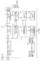
- FIG. 1schematically illustrates a driving apparatus of the liquid crystal display of the related art.
- the driving apparatus of the liquid crystal display of the related artcomprises a liquid crystal panel 2 in which m ⁇ n liquid crystal cells are arranged in a matrix and m data lines D 1 to Dm and n gate lines G 1 to Gn intersect.
- a TFTis formed at each interconnection.
- a data driver 4supplies a data signal to the data lines D 1 to Dm of the liquid crystal panel 22
- a gate driver 6supplies a scan signal to the gate lines G 1 to Gn
- a gamma voltage supplier 8supplies a gamma voltage to the data driver 4 .
- a timing controller 10controls the data driver 4 and the gate driver 6 by using a synchronization signal provided from a system 20 , a DC/DC converter 14 generates voltages supplied to the liquid crystal panel 2 by using a voltage supplied from a power supplier 12 and an inverter 16 drives a backlight 18 .
- the system 20supplies to the timing controller 10 vertical/horizontal synchronization signals V sync and H sync, a clock signal DCLK, a data enable signal DE and a data R, G and B.
- the liquid crystal panel 2comprises a plurality of liquid crystal cells Clc arranged in a matrix at the interconnection of the data lines D 1 to Dm and the gate lines G 1 to Gn.
- the TFT formed respectively in the liquid crystal cell Clcsupplies to the liquid crystal cell Clc the data signal supplied from the data lines D 1 to Dm in response to the scan signal supplied from the gate line G.
- a storage capacitor Cstis formed in each liquid crystal cell Clc.
- the storage capacitor Cstis formed between a pixel electrode of the liquid crystal cell Clc and a pre-staged gate line or is formed between the pixel electrode of the liquid crystal cell Clc and a common electrode line, thereby maintains a uniform voltage of the liquid crystal cell Clc.
- the gamma voltage supplier 8provides a plurality of gamma voltages to the data driver 4 .
- the data driver 4converts a digital video data R, G, and B into an analog gamma voltage (data signal) corresponding to a gray scale value in response to a control signal Cs from the timing controller 10 and supplies the analog gamma voltage to the data lines D 1 to Dm.
- the gate driver 6sequentially supplies a scan pulse to the gate lines G 1 to Gn in response to the control signal CS from the timing controller 10 to select a horizontal line of the liquid crystal panel 2 to which the data signal is supplied.
- the timing controller 10generates the control signal CS for controlling the gate driver 6 and the data driver 4 by using the vertical/horizontal synchronization signals Vsync and Hsync and the clock signal DCLK received from the system 20 .
- the control signal CS for controlling the gate driver 6comprises a gate start pulse GSP, a gate shift clock GSC and a gate output enable GOE etc.
- the control signal CS for controlling the data driver 4comprises a source start pulse GSP, a source shift clock SSC, a source output enable SOC and a polarity signal POL etc.
- the timing controller 10rearranges the data R, G, and B supplied from the system 20 to supply the rearranged data to the data driver 4 .
- the DC/DC converter 14increases or decreases 3.3 V of a voltage received from the power supplier 12 to produce a voltage to be supplied to the liquid crystal panel 2 .
- the DC/DC converter 14generates a gamma reference voltage, a gate high voltage VGH, a gate low voltage VGL and a common voltage Vcom.
- the inverter 16supplies a driving voltage (or a driving current) for driving the backlight 18 to the backlight 18 .
- the backlight 18generates light corresponding to the driving voltage (or the driving current) supplied from the inverter 16 to supply the driving voltage to the liquid crystal panel 2 .
- the contrastshould be clear.
- the backlight 18 of the liquid crystal displayconstantly and uniformly radiates irrespective of the data. If the backlight 18 constantly and uniformly radiates irrespective of the data, it is difficult to display dynamic and vivid pictures in the liquid crystal panel 2 . For example, if an explosion scene is to be vividly displayed, the brightness of the explosion scene should be emphasized.
- the backlight 18constantly radiates irrespective of data in the liquid crystal display of the related art, it is difficult to represent the vivid picture. That is, it is impossible to partially emphasize the brightness in the related art.
- one advantage of the embodiments of the present inventionare that they provide a method and apparatus for driving a liquid crystal display capable of changing the brightness of a display picture in accordance with input data information and partially emphasizing the brightness.
- an apparatus for driving the liquid crystal displaycomprises a picture quality improving unit that that receives first data, extracts a brightness component for at least one liquid crystal cell of the liquid crystal display from the first data, analyzes brightness of the first data using the extracted brightness component, and generates second data having a contrast extended from that of the first data in accordance with the analyzed brightness; a timing controller that rearranges the second data to supply the second data to a data driver; a backlight that supplies light to the liquid crystal panel in accordance with a driving voltage or current; and an inverter that supplies the driving voltage or current to the backlight.
- the invertermay receive a brightness control signal corresponding to the brightness component of the first data from the picture quality improving unit, and supply the driving current corresponding to the brightness control signal to the backlight.
- the picture quality improving unitmay generate the brightness control signal so that light proportional to the brightness of the brightness component is supplied to the liquid crystal panel from the backlight.
- the picture quality improving unitmay comprise: an image signal modulation unit that generates the second data using the first data; a backlight control unit that generates the brightness control signal through control of the image signal modulation unit; and a controller that receives a first synchronization signal and changes a received first synchronization signal in synchronization with the second data to supply the first synchronization signal synchronized to the second data to the timing controller.
- the image signal modulation unitmay comprise: a brightness/color dividing unit that converts the first data into the brightness component and a color-difference component; a histogram analyzer that accumulates the brightness components of a plurality of the liquid crystal cells in each frame into a histogram corresponding to a gray scale to determine brightness information; a histogram modulation unit that generates, for each of at least some of the brightness components, a modulated brightness component having a contrast extended from that of the brightness component using the histogram analyzed from the histogram analyzer; and a brightness/color mixing unit that generates the second data using one of the modulated brightness components and the associated color-difference component.
- the image signal modulation unitmay further comprise a delaying unit that delays each color-difference component until the brightness information is determined in the histogram analyzer.
- the histogram modulation unitmay darken a dark part of the brightness component and brighten a bright part to generate the modulated brightness component.
- the image signal modulation unitmay further comprise: a lookup table that provides reference data used to generate the brightness component in the backlight control unit and the brightness control signal corresponding to the modulated brightness component in the histogram modulation unit; and a memory that temporarily stores the reference data extracted from the lookup table.
- the histogram analyzermay supply at least one of a minimum value of brightness, a maximum value of brightness and an average value of brightness to the backlight control unit, and the backlight control unit may generate the brightness control signal in accordance with the at least one of the minimum value of brightness, the maximum value of brightness and the average value of brightness.
- the backlight control unitmay comprise: a backlight controller that generates the brightness control signal; and a digital/analog converter that converts the brightness control signal generated by the backlight controller into an analog signal.
- the liquid crystal panelmay be divided into a plurality of regions and the backlight comprises a plurality of lamps, each of the lamps providing light to a different region of the plurality of regions.
- the histogram analyzermay analyze the histogram to supply at least one of a frequency of the gray scale for each region, a total frequency of the gray scale, a minimum brightness for each region, and a maximum brightness for each region to the backlight control unit.
- the backlight control unitmay generate a region brightness control signal supplied to the inverter and subsequently to the lamps such that light proportional to a brightness of each region is supplied from one of the lamps.
- a method for driving a liquid crystal displaycomprises: accumulating received first data into a histogram corresponding to a gray scale to analyze brightness information; converting the first data into second data having a contrast extended from that of the first data using the brightness information; and rearranging the second data and supplying the second data to a data driver.
- the methodmay further comprise analyzing the brightness information of each frame.
- the methodmay further comprise controlling a backlight in accordance with the brightness information.
- the light supplied to a liquid crystal panel from the backlightmay be controlled in proportion to a brightness of the brightness information.
- the methodmay further comprise converting synchronization signals to synchronize with the second data.
- a method for driving a liquid crystal displaycomprises: converting received first data of each of a plurality of liquid crystal cells in a liquid crystal panel into a brightness component and a color-difference component; accumulating the brightness components of a frame into a histogram to analyze brightness information; altering the histogram such that a contrast of each of at least some of the brightness components is extended to generate a converted brightness component; generating second data of which the contrast is extended using the converted brightness component and the associated color-difference component; and rearranging the second data and supplying the second data to the liquid crystal panel through a data driver.
- the methodmay further comprise delaying the color-difference component to synchronize the color-difference component and the converted brightness component.
- the methodmay further comprise converting synchronization signals to synchronize with the second data.
- the methodmay further comprise controlling a backlight in accordance with the brightness information.
- the methodmay further comprise controlling light supplied to the liquid crystal panel from the backlight in proportion to brightness of the brightness information.
- the liquid crystal panelmay be divided into a plurality of regions and the method further comprise supplying each region with light from one lamp of a plurality of lamps of the backlight.
- the methodmay further comprise analyzing the brightness information of each region and producing region brightness information for each region.
- the methodmay further comprise controlling light of each of the lamps in proportion to the brightness of the region brightness information.
- the methodmay further comprise providing, from a lookup table, reference data used to control the backlight and to alter the histogram.
- the methodmay further comprise temporarily storing the reference data extracted from the lookup table in a memory prior to supplying the reference data.
- the methodmay further comprise experimentally determining the reference data.
- the methodmay further comprise experimentally determining the information prior to the histogram being accumulated.
- an apparatus that increases contrast of images displayed in a liquid crystal displaycomprises a picture quality improving unit that extracts a brightness component from received first data, generates a modified brightness component having a different gray scale value than the brightness component, and produces second data using the modified brightness component, wherein an image produced using the second data has a higher contrast than an image produced using the first data.
- the apparatusmay further comprise a data driver that supplies the second data to liquid crystal cells of a liquid crystal panel of the liquid crystal display.
- the apparatusmay further comprise a backlight that supplies light to the liquid crystal panel proportional to the brightness component.
- the apparatusmay further comprise a timing controller that rearranges the second data and supplies the rearranged second data to the data driver, wherein the picture quality improving unit comprises: an image signal modulation unit that generates the second data; a backlight control unit that generates a brightness control signal that controls the backlight; and a controller that synchronizes a synchronization signal with the second data and supplies the synchronization signal to the timing controller.
- the picture quality improving unitcomprises: an image signal modulation unit that generates the second data; a backlight control unit that generates a brightness control signal that controls the backlight; and a controller that synchronizes a synchronization signal with the second data and supplies the synchronization signal to the timing controller.
- the image signal modulation unitmay comprise: a brightness/color dividing unit that converts the first data into the brightness component and a color-difference component; a histogram analyzer that accumulates, for a particular frame, the brightness components of a plurality of the liquid crystal cells into a histogram to determine brightness information; a histogram modulation unit that generates, for each of at least some of the brightness components, the modulated brightness components using the histogram analyzed from the histogram analyzer; and a brightness/color mixing unit that generates the second data using one of the modulated brightness components and the color-difference component associated with the brightness component from which the one of the modulated brightness components was generated.
- the image signal modulation unitmay further comprise a delaying unit that delays the associated color-difference component such that the one of the modulated brightness components and the associated color-difference component are supplied synchronously to the brightness/color mixing unit.
- the histogram modulation unitmay generate the modulated brightness components for the brightness components of each of the liquid crystal cells.
- the histogram modulation unitmay generate the modulated brightness components for the brightness components in each frame.
- the image signal modulation unitmay further comprise a lookup table that provides reference data used, in the backlight control unit, to control the backlight and, in the histogram modulation unit, to generate the modulated brightness component.
- the image signal modulation unitmay further comprise a memory that temporarily stores the reference data extracted from the lookup table.
- the reference datamay exist in the lookup table prior to the histogram being accumulated.
- the histogram analyzermay supply at least one of a minimum value of brightness, a maximum value of brightness and an average value of brightness to the backlight control unit, and the backlight control unit may generate the brightness control signal in accordance with the at least one of the minimum value of brightness, the maximum value of brightness and the average value of brightness.
- the backlight control unitmay comprise: a backlight controller that generates the brightness control signal; and a digital/analog converter that converts the brightness control signal generated by the backlight controller into an analog signal.
- the backlightmay comprise a plurality of lamps, each of the lamps providing light to a different region of the liquid crystal panel.
- the histogram analyzermay analyze the histogram to supply at least one of a frequency of the gray scale for each region, a total frequency of the gray scale, a minimum brightness for each region, and a maximum brightness for each region to the backlight control unit.
- the backlight control unitmay generate a region brightness control signal that controls the lamps such that light proportional to a brightness of each different region is supplied by a different one of the lamps.
- FIG. 1is a block diagram illustrating a driving apparatus of a liquid crystal display of the related art
- FIG. 2is a block diagram illustrating a driving apparatus of a liquid crystal display according to an embodiment of the present invention
- FIG. 3is a block diagram illustrating in full detail a picture quality improving unit shown in FIG. 2 ;
- FIG. 4illustrates a brightness component analyzed in a histogram analyzer shown in FIG. 2 ;
- FIG. 5illustrates a brightness component modulated in a histogram modulation unit shown in FIG. 2 ;
- FIG. 6is a comparison of a picture according to an embodiment of the present invention that of the related art.
- FIG. 7is a block diagram illustrating a driving apparatus of a liquid crystal display according to the other embodiment of the present invention.
- FIG. 8is a block diagram illustrating in full detail a picture quality improving unit shown in FIG. 7 ;
- FIG. 9is a picture of a liquid crystal display according to another embodiment of the present invention.
- FIG. 2is a block diagram illustrating a driving apparatus of a liquid crystal display according to a first embodiment of the present invention.
- the driving apparatus of the liquid crystal displaycomprises a liquid crystal panel 22 where m ⁇ n liquid crystal cells are arranged in a matrix and m data lines D 1 to Dm and n gate lines G 1 to Gn intersect with a TFT formed at each interconnection.
- a data driver 24supplies a data signal to the data lines D 1 to Dm of the liquid crystal panel 22
- a gate driver 26supplies a scan signal to the gate lines G 1 to Gn
- a gamma voltage supplier 28supplies a gamma voltage to the data driver 24 .
- a timing controller 30controls the data driver 24 and the gate driver 26 using a second synchronization signal provided from a picture quality improving unit 42 , a DC/DC converter 34 generates voltages supplied to the liquid crystal panel 22 using a voltage supplied from a power supplier 32 , an inverter 36 drives a backlight 38 and a picture quality improving unit 42 extends the contrast of input data and supplies a brightness control signal (Dimming) corresponding to the input data to the inverter 36 .
- a brightness control signalDimming
- the system 40supplies to the picture quality improving unit 42 first vertical/horizontal synchronization signals Vsync 1 and Hsync 1 , a first clock signal DCLK 1 , a first data enable signal DE 1 and first data Ri, Gi and Bi which are the red, green, and blue levels for each of the liquid crystal cells Clc of the liquid crystal panel 22 .
- the liquid crystal panel 22comprises a plurality of liquid crystal cells Clc arranged in a matrix at the intersection of the data lines D 1 to Dm and the gate lines G 1 to Gn.
- the TFT formed respectively in each liquid crystal cell Clcsupplies to the liquid crystal cell Clc the data signal supplied from the data lines D 1 to Dm in response to the scan signal supplied from the gate line G.
- a storage capacitor Cstis formed in each liquid crystal cell Clc.
- the storage capacitor Cstis formed between a pixel electrode of the liquid crystal cell Clc and a pre-staged gate line or is formed between the pixel electrode of the liquid crystal cell Clc and a common electrode line to thereby uniformly maintain a voltage of the liquid crystal cell Clc.
- the gamma voltage supplier 28provides a plurality of gamma voltages to the data driver 24 .
- the data driver 24converts digital video data Ro, Go, and Bo into an analog gamma voltage (data signal) corresponding to a gray scale value in response to a control signal Cs from the timing controller 30 to supply the analog gamma voltage to the data lines D 1 to Dm.
- the gate driver 26sequentially supplies a scan pulse to the gate lines G 1 to Gn in response to the control signal CS from the timing controller 30 to select a horizontal line of the liquid crystal panel 22 to which the data signal is supplied.
- the timing controller 30generates a control signal (CS) that controls the gate driver 26 and the data driver 24 using the second vertical/horizontal synchronization signals Vsync 2 and Hsync 2 and the second clock signal DCLK 2 received from the picture quality improving unit 42 .
- the control signal CS that controls the gate driver 26comprises a gate start pulse GSP, a gate shift clock GSC and a gate output enable GOE etc.
- the control signal CS that controls the data driver 24comprises a source start pulse SSP, a source shift clock SSC, a source output enable SOC and a polarity signal POL.
- the timing controller 30rearranges the second data Ro, Go and Bo supplied from the picture quality improving unit 42 to supply the rearranged second data to the data driver 24 .
- the DC/DC converter 34may increase or decrease a 3 . 3 V voltage provided from the power supplier 32 to produce a voltage to be supplied to the liquid crystal panel 22 .
- the DC/DC converter 34generates a gamma reference voltage, a gate high voltage VGH, a gate low voltage VGL and a common voltage Vcom.
- the inverter 36supplies to the backlight 38 a driving voltage (or driving current) corresponding to a brightness control signal supplied from the picture quality improving unit 42 .
- the driving voltage or current supplied from the inverter 36 to the backlight 38is determined by the brightness control signal supplied from the picture quality improving unit 42 .
- the backlight 38supplies to the liquid crystal panel 22 light of a brightness corresponding to the driving voltage or current supplied from the inverter 36 .
- Either an edge-type system or a direct-below type systemmay be selected as the backlight 38 .
- the lampis installed on the outside of the liquid crystal panel and the light incident from the lamp is supplied to the entire surface of the liquid crystal panel through a transparent light guide panel.
- a direct-below type systemone or more light sources are mounted on the rear surface of the liquid crystal panel, and the light from the lamp is directly supplied to the liquid crystal panel.
- a direct-below type systemmay have a higher brightness and a wider light surface compared with the edge-type system, as well as fewer components.
- the picture quality improving unit 42extracts a brightness component for each liquid crystal cell Clc using the first data Ri, Gi and Bi received from the system 40 and generates second data Ro, Go and Bo which have a different gray scale value than that of the first data Ri, Gi and Bi.
- the picture quality improving unit 42also generates a brightness control signal corresponding to the extracted brightness component to supply the brightness control signal to the inverter 36 .
- the picture quality improving unit 42generates second vertical/horizontal synchronization signals Vsync 2 and Hsync 2 , a second clock signal DCLK 2 and a second data enable signal DE 2 synchronized to the second data Ro, Go and Bo using the first vertical/horizontal synchronization signal Vsync 1 and Hsync 1 , a first clock signal DCLK 1 and a first data enable signal DE 1 received from the system 40 .
- the picture quality improving unit 42includes an image signal modulation unit 70 that generates the second data Ro, Go and Bo using the first data Ri, Gi and Bi, a backlight controller unit 72 that generates the brightness control signal (Dimming) through control of the image signal modulation unit 70 and a controller 68 that generates the second vertical/horizontal synchronization signals Vsync 2 and Hsync 2 , the second clock signal DCLK 2 and the second data enable signal DE 2 .
- the image signal modulation unit 70extracts a brightness component Y from the first data Ri, Gi and Bi and generates the second data Ro, Go and Bo.
- the second data Ro, Go and Bohas a gray scale value that is changed.
- the image signal modulation unit 70comprises a brightness/color dividing unit 50 , a delaying unit 52 , a brightness/color mixing unit 54 , a histogram analyzer 56 , a histogram modulation unit 58 , a memory 64 and a lookup table 66 .
- the brightness/color dividing unit 50divides the first data Ri, Gi and Bi of each liquid crystal cell Clc of the liquid crystal panel 22 into the brightness component Y and color-difference components U and V.
- the brightness component Y and color-difference components U and V for a particular liquid crystal cellare determined using Equations 1 to 3.
- Y0.229 ⁇ Ri +0.587 ⁇ Gi +0.114 ⁇ Bi
- U0.493 ⁇ ( Bi ⁇ Y )
- V0.887 ⁇ ( Ri ⁇ Y ) [Equation 3]
- the histogram analyzer 56collects the brightness components of the liquid crystal cells Clc in each frame into a histogram or gray scale, such as that shown in FIG. 4 . Brightness information of the image is then obtained by analyzing the histogram. For example, if the histogram is inclined to right (high gray scale), the image is primarily bright, and if the histogram is inclined to left (low gray scale), the image is primarily dark.
- the histogram analyzer 56analyzes the histogram of the brightness component Y of each frame to determine the brightness information of the frame (e.g. a minimum value, a maximum value and an average value of the brightness). The histogram analyzer 56 then supplies at least one of the minimum value, the maximum value and the average value to the backlight control unit 72 .
- the histogram modulation unit 58receives the brightness information and the histogram from the histogram analyzer 56 .
- the histogram modulation unit 58then generates a modulated brightness component YM for each original brightness component Y and thus extends the contrast of the original histogram.
- the modulated brightness component YMis determined from modulation data stored in the lookup table 66 .
- the lookup table 66a variety of modulation data corresponding to the brightness information is stored in the lookup table 66 .
- the modulation data of various patternsis stored in the lookup table 66 so that the contrast is correspondingly extended to the designated brightness information.
- the histogram modulation unit 58refers to the modulation data stored in the lookup table 66 to generate each modulated brightness component YM as shown in FIG. 5 .
- the brightness componentsare divided into over 200 channels (different brightness components), although the exact number of channels into which the brightness data is disposed depends on the desired resolution, with an increase in channels providing better image display but more computation power.
- the gray scale of the modulated brightness components YMis distributed over substantially the entire region of the histogram. As described above, if the brightness components YM are distributed over substantially the entire region, the contrast is increased and thus the image appears more clearly.
- the modulation data stored in the lookup table 66may be determined experimentally so that the contrast is extended with relation to various histograms. The information in the lookup table 66 thus may be determined prior to the histogram being accumulated in the histogram analyzer 56 .
- the lookup table 66may be stored in the memory 64 . It should be understood that the lookup table 66 is illustrated as being separate from the memory 64 in order to more clearly indicate the lookup table 66 . In addition, the modulated data extracted from the lookup table 66 can be temporarily stored in the memory 64 .
- the driving voltage or currentwhich is supplied to the backlight 38 , is stored in the lookup table 66 and corresponds to at least one of the minimum value, the maximum value and the average value of the brightness in the lookup table 66 .
- the driving voltage or current stored in the lookup table 66is set so that the contrast is extended as determined by various experiments, which may be performed before the display is shipped from the manufacturer or in situ as the display is used.
- the delaying unit 52delays the color-difference components U and V during analyzation of the brightness components Y in the histogram analyzer 56 and the histogram modulation unit 58 .
- the delaying unit 52then supplies the delayed color-difference components UD and VD which are synchronized with the modulated brightness components YM to the bright/color mixing unit 54 .
- the brightness/color mixing unit 54generates the second data Ro, Go and Bo for each liquid crystal cell Clc in the frame using the modulated brightness component YM and the delayed color-difference components UD and VD.
- the second data Ro, Go and Boare determined using Equations 4 to 6.
- RoYM +0.000 ⁇ U +1.140 ⁇ V
- GoYM ⁇ 0.396 ⁇ U ⁇ 0.581 ⁇ V
- BoYM +2.029 ⁇ U +0.000 ⁇ V
- Equation 6
- the brightness/color dividing unit 50divides the first data Ri, Gi and Bi of each liquid crystal cell Clc in a particular frame, using the Equations 1 to 3, into the brightness component Y and the color-difference components U and V.
- the brightness components Yare provided to the histogram analyzer 56 and the color-difference components U and V are provided to the delaying unit 52 .
- the histogram analyzer 56accumulates the brightness components Y into a gray scale for each frame and analyzes the brightness information (e.g. a minimum value, a maximum value and an average value of the brightness) from the gray scale. The histogram analyzer 56 then supplies the brightness information 56 to the backlight control unit 72 and supplies the brightness information and the histogram information to the histogram modulation unit 58 .
- the brightness informatione.g. a minimum value, a maximum value and an average value of the brightness
- the histogram modulation unit 58refers to the lookup table 66 to extend the contrast of the histogram received thereto. In other words, the histogram modulation unit 58 generates an extended brightness component YM for each original brightness component Y. The histogram modulation unit 58 thus generates an extended and modulated histogram and supplies the brightness components YM to the brightness/color mixing unit 54 so that the histogram may be distributed over substantially the entire region. In one example of an extended histogram, the spread between the maximum and minimum modified brightness components is wider than that of the maximum and minimum original brightness components.
- the brightness/color mixing unit 54in response to the delayed color-difference component UD and VD and the modulated brightness component YM generates the second data Ro, Go and Bo using the Equations 4 to 6 for each liquid crystal cell Clc. Since the second data Ro, Go and Bo are generated by the modulated brightness component YM, this provides a clear brightness and darkness for the displayed image. That is, the brightness component YM is distributed over substantially the entire gray scale region to generate second data Ro, Go and Bo having a clear brightness and darkness, whereby vivid pictures can be displayed in the liquid crystal panel 22 . In other words, bright colors become brighter and dark color become darker. Thus, the contrast is improved.
- the backlight control unit 72extracts the driving voltage or current from the lookup table 66 in accordance with at least one of the minimum value, the maximum value and the average value of the brightness supplied from the histogram analyzer 56 to generate a brightness control signal corresponding to the extracted data.
- the brightness control signal generated from the backlight control unit 72is supplied to the inverter 36 .
- the backlight control unit 72comprises a backlight controller 60 and a digital/analog converter 62 .
- the backlight controller 60extracts a driving voltage or current from the lookup table 66 that corresponds to at least one of the minimum value, the maximum value and the average value of the brightness supplied from the histogram analyzer 56 to generate a brightness control signal corresponding to the extracted data. More specifically, if the brightness signal analyzed in the histogram analyzer 56 has a high brightness, the backlight controller 60 generates a digital control signal to produce light of a high brightness. However if the brightness signal analyzed in the histogram analyzer 56 has a low brightness, the backlight controller 60 generates a digital control signal to produce light of a low brightness.
- the digital to analog converter 62converts the digital control signal into an analog control signal and supplies the analog control signal to the inverter 36 .
- the inverter 36in response to the analog brightness control signal, supplies a driving voltage or current corresponding to the brightness control signal to the backlight 38 .
- the backlight 38generates light of a brightness corresponding to the driving voltage or current supplied from the inverter 36 , which is then supplied to the liquid crystal panel 22 . That is, the backlight controller 60 controls light from the backlight 38 so that bright colors are displayed more brightly and dark colors are displayed more darkly. This permits pictures with a higher contrast to be displayed in the liquid crystal panel 22 .
- the controller 68receives the first vertical/horizontal synchronization signals Vsync 1 and Hsync 1 , the first clock signal DCLK 1 , and the first data enable signal DE 1 provided from the system 40 .
- the controller 68generates the second vertical/horizontal synchronization signals Vsync 2 and Hsync 2 , the second clock signal DCLK 2 and the second data enable signal DE 2 in synchronization with the second data Ro, Go and Bo and supplies the second vertical/horizontal synchronization signals, the second clock signal and the second data enable signal to the timing controller 30 .
- the liquid crystal display apparatus of the above embodiment ofincreases the contrast of the entire display using the brightness component of the data to display dynamic and vivid pictures.
- Bright partse.g. lines
- dark partsshadows, tracks
- the brightness of the backlight 38is also adjusted in accordance with the brightness of the image in each frame to thereby display vivid and dynamic pictures as shown in FIG. 6 .
- the brightness of the backlight 38is accordingly decreased.
- the tube current of the backlight 38is adjusted to thereby reduce the power consumption of the backlight 38 .
- FIG. 7is a block diagram illustrating a driving apparatus of the liquid crystal display according to a second embodiment of the present invention.
- the same reference numeralsare assigned to blocks performing the same functions at that shown in FIG. 2 , and detailed explanations of these blocks will be omitted.
- the liquid crystal display according to the second embodiment of the present inventioncomprises a liquid crystal panel 22 having a TFT formed at intersections wherein m ⁇ n liquid crystal cells Clc are arranged in a matrix of m data lines D 1 to Dm and n gate lines G 1 to Gn, a data driver 24 supplies data signals to the data lines D 1 to Dm of the liquid crystal panel 22 , a gate driver 26 supplies scan signals to the gate lines G 1 to Gn, and a gamma voltage supplier 28 supplies gamma voltages to the data driver 24 .
- a timing controller 30controls the data driver 24 and the gate driver 26 using the second synchronization signal supplied from the picture quality improving unit 80 , a DC/DC converter 34 generates voltages supplied to the liquid crystal panel 22 using the voltage provided from the power supply 32 , an inverter 82 drives the backlight 84 , and a picture quality improving unit 80 supplies to the inverter 82 brightness control signals Dimming 1 to Dimming i that individually control a plurality of lamps 90 1 , 90 2 , 90 3 , . . . , 90 i (i is an integer) and extends the contrast of the input data.
- the system 40supplies a first vertical/horizontal synchronization signal Vsync 1 and Hsync 1 , a first clock signal DCLK 1 , a first data enable signal DE 1 and first data Ri, Gi, and Bi to the picture quality improving unit 42 .
- the liquid crystal displaycomprises liquid crystal cells Clc disposed in a matrix.
- the liquid crystal cells Clcdisplay a designated picture corresponding to the data signal supplied from the data driver 24 .
- the gamma voltage supplier 28supplies a plurality of gamma voltages to the data driver 24 .
- the data driver 24converts the video data Ro, Go, and Bo supplied thereto to the data signal using a gamma voltage, and supplies the data signal to the data lines D 1 to Dm.
- the gate driver 26sequentially supplies a scan pulse to the gate lines G 1 to Gn to select a particular liquid crystal cell.
- the timing controller 30generates a control signal CS that controls the gate driver 26 and the data driver 24 using a second vertical/horizontal synchronization signal Vsync 2 and Hsync 2 provided from the picture quality improving unit 80 .
- the timing controller 30rearranges the second data Ro, Go, and Bo provided from the picture quality improving unit 80 to supply the provided data to the data driver 24 .
- the DC/DC converter 34steps-up or steps-down 3.3 volts provided from the power supplier 32 to generate a gamma reference voltage, a gate high voltage VGH, a gate low voltage VGL and a common voltage Vcom.
- the inverter 82supplies to the backlight 84 the driving voltage or current corresponding to the brightness control signals Dimming 1 to Dimming i supplied from the picture quality improving unit 80 .
- the picture quality improving unit 80supplies i brightness control signals Dimming 1 to Dimming i (i.e. the total number of brightness control signals) to the inverter in order to each of the lamps 90 1 to 90 i .
- the inverter 82supplies driving voltages or currents respectively corresponding to the i brightness control signals Dimming 1 to Dimming i to the lamps 90 1 to 90 i .
- the driving voltages or currentsmay be different from or identical to each other. That is, the brightness of the lamps 90 1 to 90 i within one frame can be set differently. Essentially, the lamps 90 1 to 90 i correspond to the brightness control signals Dimming 1 to Dimming i to selectively control the brightness of light provided to the liquid crystal panel 22 .
- the direct-below type systemincluding a plurality of lamps 90 1 to 90 i is employed.
- a plurality of lamps 90 1 to 90 iare mounted on the rear surface of the liquid crystal panel 22 to supply to the liquid crystal panel light corresponding to the driving voltage or current supplied from the inverter 82 .
- the liquid crystal panel 22corresponds to mounting location of the lamps 90 1 to 90 i and can be divided into i regions.
- the liquid crystal panel 22can be divided into a first region having light supplied from the first lamp 90 1 , a second region having light supplied from the second lamp 90 2 , and an i th region having light supplied from the i th lamp 90 i , etc.
- the picture quality improving unit 80generates bright control signals Dimming 1 to Dimming i in accordance with the data supplied to each of the regions of the liquid crystal panel 22 .
- the picture quality improving unit 80extracts the brightness component of each liquid crystal cell Clc in a particular frame using the first data Ri, Gi, and Bi provided from the system 40 to generate the second data Ro, Go, and Bo, changing the gray scale value of the first data Ri, Gi, and Bi.
- the picture quality improving unit 80generates i brightness control signals Dimming 1 to Dimming i using the brightness components and frequency provided to i regions of the liquid crystal panel 22 and supplies the generated brightness control signals Dimming 1 to Dimming i to the inverter 82 .
- the picture quality improving unit 80generates the second vertical/horizontal synchronization signal Vsync 2 and Hsync 2 , the second clock signal DCLK 2 and the second data enable signal DE 2 synchronized with the second data Ro, Go, and Bo using the first vertical/horizontal synchronization signal Vsync 1 and Hsync 1 , the first clock signal DCLK 1 , and the first data enable signal DE 1 provided from the system 40 .
- the construction of the picture quality improving unit 80is shown in FIG. 8 .
- FIG. 8illustrates the picture quality improving unit 80 according to the second embodiment of the present invention.
- the same reference numeralsare assigned to blocks performing the same functions as in FIG. 3 . Thus, detailed explanations of these blocks will be omitted.
- the picture quality improving unit 80comprises an image signal modulation unit 102 that generates the second data Ro, Go, and Bo using the first data Ri, Gi, and Bi, a backlight control unit 88 that generates the brightness control signals Dimming 1 to Dimming i through control of the image signal modulation unit 102 , and a controller 68 that generates the second vertical/horizontal synchronization signal Vsync 1 and Hsync 1 , the second clock signal DCLK 2 and the second data enable signal DE 2 .
- the image signal modulation unit 102extracts the brightness component Y from the first data Ri, Gi and Bi and generates the second data Ro, Go and Bo having an altered gray scale value using the extracted brightness component Y.
- the image signal modulation unit 102controls the backlight control unit 88 referring to the brightness and the frequency of the data respectively supplied to the i regions of the liquid crystal panel 22 .
- the image signal modulation unit 102comprises a brightness/color dividing unit 50 , a delaying unit 52 , a brightness/color mixing unit 54 , a histogram analyzer 90 , a histogram modulation unit 58 , a memory 100 and a lookup table 98 .
- the brightness/color dividing unit 50divides the first data Ri, Gi, and Bi of each liquid crystal cell Clc of each frame into a brightness component Y and color difference components U and V using Equations 1 to 3.
- the histogram analyzer 90accumulates the brightness components Y of each frame into the gray scale of the frame. In other words, the histogram analyzer 90 collects the brightness components Y and separates the brightness components Y into a gray scale to acquire the histogram shown in FIG. 4 . Thus, a total frequency of each gray scale can be acquired.
- the histogram analyzer 90analyzes at least one of the minimum brightness, the maximum brightness and the region frequency of the gray scale for each of the i regions of the liquid crystal panel. Explaining this in more detail, the liquid crystal panel 22 is divided into i regions that correspond to the lamps 90 1 to 90 i .
- the histogram analyzer 90analyzes the gray scale value for each of the regions of the brightness (including the minimum brightness and the maximum brightness) and the region frequency of the gray scale supplied to each of the regions of the liquid crystal panel 22 .
- the histogram analyzer 90supplies at least one of the total frequency of the analyzed gray scale, the region frequency of the gray scale and the gray scale value for each region to the backlight control unit 88 .
- the total frequency and the region frequencycan be supplied to the backlight control unit 88 .
- the histogram modulation unit 58receives the brightness information and the histogram from the histogram analyzer 90 to generate modulated brightness components YM in which the contrast of the received histogram is extended.
- the histogram modulation unit 58refers to the modulation data stored in the lookup table 98 to generate the modulated brightness components YM.
- Various modulation data corresponding to the brightness informationis stored in the lookup table 98 .
- the modulation data of various patternsis stored so that the contrast may be extended in accordance with the designated brightness information.
- the histogram modulation unit 58refers to the modulation data stored in the lookup table 98 to generate the modulated brightness component YM for each original brightness component Y, as shown in FIG. 5 .
- the gray scale of the modulated brightness components YMis distributed over substantially the entire region. If the brightness components YM are distributed over substantially the entire region, the contrast between darkness and brightness can be increased.
- the modulation data stored in the lookup table 98is determined experimentally so that the contrast may be extended in accordance with the various histograms.
- the lookup table 98may be stored in the memory 100 , although as shown in FIG. 8 , the memory 100 and the lookup 98 are separated and depicted in order to better represent the lookup table 98 .
- the modulation data extracted from the lookup table 98can be temporarily stored in the memory 100 .
- the driving voltage or current to be supplied to the backlight unit 84 in accordance with at least one of the total frequency of the gray scale, the region frequency of the gray scale and the gray scale value for each region (including the minimum brightness and the maximum brightness)is stored in the lookup table 98 .
- the contrast of the driving voltage or current stored in the lookup table 98is extended and the driving voltage or current is determined experimentally so that vivid pictures may be displayed.
- the delaying unit 52delays the color-difference components U and V while the brightness component Y is analyzed in the histogram analyzer 56 and the histogram modulation unit 58 .
- the brightness/mixing unit 54receives the modulated brightness component YM and the delayed color-difference components UV and VD and generates the second data Ro, Go and Bo using Equations 4 to 6 of each liquid crystal cell Clc for each frame.
- the brightness/color dividing unit 50changes the first data Ri, Gi and Bi for each liquid crystal cell Clc using Equations 1 to 3 into the brightness component Y and the color-difference components U and V.
- the brightness component Yis provided to the histogram analyzer 90
- the color-difference components U and Vare provided to the delaying unit 52 .
- the histogram analyzer 90 receiving the brightness components Yaccumulates the brightness components Y into a gray scale for each frame, and analyzes the brightness information (the region frequency for each gray scale, the total frequency for each gray scale, and the gray scale value for each region) from the brightness components Y.
- the histogram analyzer 90supplies the brightness information to the backlight control unit 88 .
- the histogram analyzer 90supplies the histogram information to the histogram modulation unit 58 .
- the histogram modulation unit 58refers to the lookup table 98 to extend the contrast of the histogram received to itself. That is, the histogram modulation unit 58 generates a brightness component YM for each original brightness component Y in which the histogram is extended.
- the brightness components YMare supplied to the brightness/color mixing unit 54 so that the histogram is distributed over substantially the entire gray scale region.
- the brightness/color mixing unit 54 receiving the delayed color-difference components UV and VD and the modulated brightness component YMgenerates the second data Ro, Go, and Bo for each liquid crystal cell Clc using Equations 4 to 6.
- the second data Ro, Go, and Bohas extended contrast because of being generated by the modulated brightness component YM. That is, the brightness components YM are distributed over substantially the entire gray scale region to generate the second data Ro, Go, and Bo having increased contrast. This allows vivid images to be displayed in the liquid crystal panel 22 . In other words, bright colors are displayed more brightly and dark colors are displayed more darkly, thereby emphasizing the overall contrast of the image.
- the backlight control unit 88extracts the driving voltage or current from the lookup table 98 in accordance with at least one of the region frequency for each gray scale, the total frequency for each gray scale and the gray scale value for each region supplied from the histogram analyzer 90 .
- the backlight control unit 88then generates the brightness control signals Dimming 1 to Dimming i corresponding to that the driving voltage or current.
- the brightness control signals Dimming 1 to Dimming icorresponds to the regions of the liquid crystal panel 22 , that is, the lamps 90 1 to 90 i to be generated.
- the brightness control signals Dimming 1 to Dimming i generated from the backlight control unit 88are supplied to the inverter 82 .
- the backlight control unit 88thus comprises a backlight controller 94 and a digital/analog converter 96 .
- the backlight controller 94extracts the driving voltage or current from the lookup table 98 in accordance with at least one of the region frequency for each gray scale, the total frequency for each gray scale and the gray scale value for each region supplied from the histogram analyzer 90 .
- the backlight controller 94then generates the brightness control signals Dimming 1 to Dimming i corresponding to that. If one or more special regions have a particularly high brightness, the brightness control signals are generated so that light of a high brightness is generated, and if the one or more special regions have a low brightness, the brightness control signal is generated so that light of a low brightness is generated.
- the digital/analog converter 96converts digital brightness control signals Dimming 1 to Dimming i supplied from the backlight controller 94 into analog brightness control signals Dimming 1 to Dimming i and supply these signals to the inverter 82 .
- the inverter 82 receiving the brightness control signals Dimming 1 to Dimming isupplies the driving voltages or currents corresponding to the brightness control signals Dimming 1 to Dimming i to the lamps 90 1 to 90 i .
- the lamps 90 1 to 90 igenerate light of a brightness corresponding to the driving voltage or current supplied from the inverter 82 to supply the generated light to the liquid crystal panel 22 .
- the brightness of the light supplied to each region of the liquid crystal panel 22is determined in accordance with the brightness of the data supplied to each region. That is, the lamps 90 1 to 90 i are controlled so that bright colors are displayed more brightly and dark colors are displayed more darkly. Thereby, pictures having obvious contrast can be better displayed in the liquid crystal panel 22 . Further, since the brightness of the light supplied for each of the regions is determined in accordance with the brightness of the data supplied to each of the regions, vivid and the dynamic pictures can be better displayed.
- the controller 68receives the first vertical/horizontal synchronization signals Vsync 1 and Hsync 1 , the first clock signal DCLK 1 , and the first data enable signal DE 1 received from the system 40 .
- the controller 68then generates the second vertical/horizontal synchronization signals Vsync 2 and Hsync 2 , the second clock signal DCLK 2 , and the second data enable signal DE 2 in synchronization with the second data Ro, Go, and BO to supply these signals to the timing controller 30 .
- the liquid crystal display according to the second embodiment of the present inventionproduces an image in which substantially the entire contrast is obvious using the brightness components Y of the data, thereby permitting vivid and dynamic pictures to be displayed. Since the brightness of the light supplied to the regions of the liquid crystal panel is controlled in accordance with the brightness of the data, dynamic moving pictures can be implemented.
- FIG. 9is an example of an image displayed using the second embodiment of the present invention in which selective emphasis within one frame illustrates that vivid and dynamic pictures can be displayed. Further, this embodiment of the present invention adaptively adjusts a tube current of the backlight 84 , thereby reducing the power consumption.
- the method and apparatus of driving the liquid crystal display according to the present inventionextracts the brightness component from the input data, and provides a dark color that is more dark and a bright color that is more bright than the extracted brightness components. This permits display of pictures in which the contrast is more obvious.
- the liquid crystal displaycontrols the brightness of the backlight in accordance with the extracted brightness component and thereby permits vivid and dynamic pictures to be displayed.
- the liquid crystal displaymay divide the liquid crystal panel into regions corresponding to a plurality of backlights and control the brightness of the backlight in accordance with the brightness of the data supplied to the divided regions. Such an arrangement provides selective emphasis of portions of the pictures.
- selective control of the brightness of the backlightpermits a reduction in the power consumption of the backlight and thus the overall liquid crystal device.
Landscapes
- Engineering & Computer Science (AREA)
- Physics & Mathematics (AREA)
- Computer Hardware Design (AREA)
- General Physics & Mathematics (AREA)
- Theoretical Computer Science (AREA)
- Chemical & Material Sciences (AREA)
- Crystallography & Structural Chemistry (AREA)
- Control Of Indicators Other Than Cathode Ray Tubes (AREA)
- Liquid Crystal Display Device Control (AREA)
Abstract
Description
Y=0.229×Ri+0.587×Gi+0.114×Bi [Equation 1]
U=0.493×(Bi−Y) [Equation 2]
V=0.887×(Ri−Y) [Equation 3]
Ro=YM+0.000×U+1.140×V [Equation 4]
Go=YM−0.396×U−0.581×V [Equation 5]
Bo=YM+2.029×U+0.000×V [Equation 6]
Claims (25)
Priority Applications (1)
| Application Number | Priority Date | Filing Date | Title |
|---|---|---|---|
| US12/128,191US7643004B2 (en) | 2003-06-20 | 2008-05-28 | Method and apparatus for driving liquid crystal display device |
Applications Claiming Priority (2)
| Application Number | Priority Date | Filing Date | Title |
|---|---|---|---|
| KR1020030040127AKR100949492B1 (en) | 2002-12-24 | 2003-06-20 | Driving Method and Driving Device of Liquid Crystal Display |
| KRP2003-40127 | 2003-06-20 |
Related Child Applications (1)
| Application Number | Title | Priority Date | Filing Date |
|---|---|---|---|
| US12/128,191DivisionUS7643004B2 (en) | 2003-06-20 | 2008-05-28 | Method and apparatus for driving liquid crystal display device |
Publications (2)
| Publication Number | Publication Date |
|---|---|
| US20040257329A1 US20040257329A1 (en) | 2004-12-23 |
| US7394448B2true US7394448B2 (en) | 2008-07-01 |
Family
ID=33516421
Family Applications (2)
| Application Number | Title | Priority Date | Filing Date |
|---|---|---|---|
| US10/734,702Expired - LifetimeUS7394448B2 (en) | 2003-06-20 | 2003-12-11 | Method and apparatus for driving liquid crystal display device |
| US12/128,191Expired - LifetimeUS7643004B2 (en) | 2003-06-20 | 2008-05-28 | Method and apparatus for driving liquid crystal display device |
Family Applications After (1)
| Application Number | Title | Priority Date | Filing Date |
|---|---|---|---|
| US12/128,191Expired - LifetimeUS7643004B2 (en) | 2003-06-20 | 2008-05-28 | Method and apparatus for driving liquid crystal display device |
Country Status (1)
| Country | Link |
|---|---|
| US (2) | US7394448B2 (en) |
Cited By (37)
| Publication number | Priority date | Publication date | Assignee | Title |
|---|---|---|---|---|
| US20060119613A1 (en)* | 2004-12-02 | 2006-06-08 | Sharp Laboratories Of America, Inc. | Methods and systems for display-mode-dependent brightness preservation |
| US20060119612A1 (en)* | 2004-12-02 | 2006-06-08 | Kerofsky Louis J | Methods and systems for image-specific tone scale adjustment and light-source control |
| US20060232544A1 (en)* | 2005-04-18 | 2006-10-19 | Renesas Technology Corporation | Liquid crystal display device |
| US20060238487A1 (en)* | 2005-03-29 | 2006-10-26 | Ming-Chia Shih | Display device and method |
| US20060244584A1 (en)* | 1999-09-21 | 2006-11-02 | Nec Corporation | Data processing device and method of controlling power consumption in back-light in data processing device |
| US20060262111A1 (en)* | 2004-12-02 | 2006-11-23 | Kerofsky Louis J | Systems and Methods for Distortion-Related Source Light Management |
| US20060267923A1 (en)* | 2004-12-02 | 2006-11-30 | Kerofsky Louis J | Methods and Systems for Generating and Applying Image Tone Scale Adjustments |
| US20060284882A1 (en)* | 2005-06-15 | 2006-12-21 | Sharp Laboratories Of America, Inc. | Methods and systems for enhancing display characteristics with high frequency contrast enhancement |
| US20060284823A1 (en)* | 2005-06-15 | 2006-12-21 | Sharp Laboratories Of America, Inc. | Methods and systems for enhancing display characteristics with frequency-specific gain |
| US20070001997A1 (en)* | 2005-06-30 | 2007-01-04 | Lg Philips Lcd Co., Ltd. | Apparatus and method of driving liquid crystal display device |
| US20070035565A1 (en)* | 2005-08-12 | 2007-02-15 | Sharp Laboratories Of America, Inc. | Methods and systems for independent view adjustment in multiple-view displays |
| US20070132708A1 (en)* | 2005-12-12 | 2007-06-14 | Industrial Technology Research Institute | Driving system for matrix type backlight module |
| US20070146236A1 (en)* | 2004-12-02 | 2007-06-28 | Kerofsky Louis J | Systems and Methods for Brightness Preservation using a Smoothed Gain Image |
| US20070291048A1 (en)* | 2004-12-02 | 2007-12-20 | Kerofsky Louis J | Systems and Methods for Tone Curve Generation, Selection and Application |
| US20080174607A1 (en)* | 2007-01-24 | 2008-07-24 | Ali Iranli | Systems and methods for reducing power consumption in a device through a content adaptive display |
| US20080184060A1 (en)* | 2007-01-31 | 2008-07-31 | International Business Machines Corporation | Facilitating recovery in a coordinated timing network |
| US20080203929A1 (en)* | 2007-02-09 | 2008-08-28 | Mun-Soo Park | Light generating device, display apparatus having the same and method of driving the same |
| US20080315785A1 (en)* | 2007-06-22 | 2008-12-25 | Price Erin L | Systems and methods for backlighting image displays |
| US20090059081A1 (en)* | 2006-02-07 | 2009-03-05 | Tte Technology, Inc. | Histogram detector for contrast ratio enhancement system |
| US20090109232A1 (en)* | 2007-10-30 | 2009-04-30 | Kerofsky Louis J | Methods and Systems for Backlight Modulation and Brightness Preservation |
| US20090109233A1 (en)* | 2007-10-30 | 2009-04-30 | Kerofsky Louis J | Methods and Systems for Image Enhancement |
| US20090141178A1 (en)* | 2007-11-30 | 2009-06-04 | Kerofsky Louis J | Methods and Systems for Backlight Modulation with Scene-Cut Detection |
| US20090140970A1 (en)* | 2007-11-30 | 2009-06-04 | Kerofsky Louis J | Methods and Systems for Weighted-Error-Vector-Based Source Light Selection |
| US20090167751A1 (en)* | 2007-12-26 | 2009-07-02 | Kerofsky Louis J | Methods and Systems for Image Tonescale Design |
| US20090167672A1 (en)* | 2007-12-26 | 2009-07-02 | Kerofsky Louis J | Methods and Systems for Display Source Light Management with Histogram Manipulation |
| US20090167671A1 (en)* | 2007-12-26 | 2009-07-02 | Kerofsky Louis J | Methods and Systems for Display Source Light Illumination Level Selection |
| US20090167673A1 (en)* | 2007-12-26 | 2009-07-02 | Kerofsky Louis J | Methods and Systems for Display Source Light Management with Variable Delay |
| US20090167789A1 (en)* | 2007-12-26 | 2009-07-02 | Kerofsky Louis J | Methods and Systems for Backlight Modulation with Image Characteristic Mapping |
| US20090189543A1 (en)* | 2008-01-25 | 2009-07-30 | Yeo Dong-Min | Method of local dimming, backlight assembly for performing the method and display apparatus having the backlight assembly |
| US20090267876A1 (en)* | 2008-04-28 | 2009-10-29 | Kerofsky Louis J | Methods and Systems for Image Compensation for Ambient Conditions |
| US20100007599A1 (en)* | 2008-07-10 | 2010-01-14 | Louis Joseph Kerofsky | Methods and Systems for Color Preservation with a Color-Modulated Backlight |
| US20100149435A1 (en)* | 2007-10-04 | 2010-06-17 | Nec Display Solutions, Ltd | Video display device and light source driving method thereof |
| US20100321574A1 (en)* | 2009-06-17 | 2010-12-23 | Louis Joseph Kerofsky | Methods and Systems for Power-Controlling Display Devices |
| US20110074803A1 (en)* | 2009-09-29 | 2011-03-31 | Louis Joseph Kerofsky | Methods and Systems for Ambient-Illumination-Selective Display Backlight Modification and Image Enhancement |
| US20110122171A1 (en)* | 2009-11-24 | 2011-05-26 | Kyungjoon Kwon | Liquid crystal display and method of local dimming thereof |
| US9330630B2 (en) | 2008-08-30 | 2016-05-03 | Sharp Laboratories Of America, Inc. | Methods and systems for display source light management with rate change control |
| US20220076606A1 (en)* | 2020-09-09 | 2022-03-10 | Samsung Display Co., Ltd. | Display apparatus and method of driving the same |
Families Citing this family (74)
| Publication number | Priority date | Publication date | Assignee | Title |
|---|---|---|---|---|
| TWI249630B (en)* | 1999-05-10 | 2006-02-21 | Matsushita Electric Industrial Co Ltd | Image display device and method for displaying image |
| US7870354B2 (en)* | 2003-11-04 | 2011-01-11 | Bakbone Software, Inc. | Data replication from one-to-one or one-to-many heterogeneous devices |
| US20070279368A1 (en)* | 2004-09-01 | 2007-12-06 | Drs Tactical Systems, Inc. | Low intensity displays compatible with night vision imaging systems |
| JP2006113311A (en)* | 2004-10-15 | 2006-04-27 | Hitachi Displays Ltd | Display device |
| US7924261B2 (en)* | 2004-12-02 | 2011-04-12 | Sharp Laboratories Of America, Inc. | Methods and systems for determining a display light source adjustment |
| KR101266672B1 (en)* | 2004-12-29 | 2013-05-28 | 엘지디스플레이 주식회사 | Liquid crystal display and controlling method thereof |
| KR101136185B1 (en)* | 2004-12-30 | 2012-04-17 | 엘지디스플레이 주식회사 | Liquid Crystal Display device and method for driving the same |
| EP2398016A1 (en)* | 2005-01-25 | 2011-12-21 | Sharp Kabushiki Kaisha | Display device, instrument panel, automatic vehicle, and method of driving display device |
| US7598679B2 (en)* | 2005-02-03 | 2009-10-06 | O2Micro International Limited | Integrated circuit capable of synchronization signal detection |
| KR100750130B1 (en)* | 2005-03-23 | 2007-08-21 | 삼성전자주식회사 | Light emitting assembly, backlight unit and display |
| JP2006276677A (en)* | 2005-03-30 | 2006-10-12 | Toshiba Corp | Display device and driving method of display device |
| JP2006284901A (en)* | 2005-03-31 | 2006-10-19 | Toshiba Corp | Flat-panel image display device and driving method thereof |
| KR101113236B1 (en)* | 2005-04-26 | 2012-02-20 | 삼성전자주식회사 | Backlight unit for dynamic image and display device using same |
| DE102005020568A1 (en)* | 2005-04-30 | 2006-11-09 | Osram Opto Semiconductors Gmbh | Light source arrangement for backlighting of display devices and display device |
| KR101169051B1 (en)* | 2005-06-30 | 2012-07-26 | 엘지디스플레이 주식회사 | Liquid crystal display and method for driving the same |
| KR101174782B1 (en)* | 2005-06-30 | 2012-08-20 | 엘지디스플레이 주식회사 | Apparatus and Method for Driving Liquid Crystal Display Device |
| KR101137844B1 (en)* | 2005-06-30 | 2012-04-23 | 엘지디스플레이 주식회사 | A liquid crystal display device |
| KR100698126B1 (en)* | 2005-07-01 | 2007-03-26 | 엘지전자 주식회사 | Power control device and method of display module |
| KR100653070B1 (en)* | 2005-09-05 | 2006-12-01 | 삼성전자주식회사 | LCD Display |
| KR101006385B1 (en)* | 2005-11-16 | 2011-01-11 | 삼성전자주식회사 | Display device and control method thereof |
| US7746330B2 (en)* | 2005-12-22 | 2010-06-29 | Au Optronics Corporation | Circuit and method for improving image quality of a liquid crystal display |
| US20090015602A1 (en)* | 2006-01-11 | 2009-01-15 | Tte Technology, Inc. | Contrast Ratio Enhancement System Using Asymmetrically Delayed Illumination Control |
| JP4071800B2 (en)* | 2006-02-13 | 2008-04-02 | シャープ株式会社 | Moving picture reproduction apparatus and gradation correction apparatus |
| JP5176397B2 (en)* | 2006-06-01 | 2013-04-03 | ソニー株式会社 | Display device and driving method thereof |
| KR101361047B1 (en) | 2006-06-01 | 2014-02-10 | 소니 주식회사 | Display device and driving method thereof |
| US20070285379A1 (en)* | 2006-06-09 | 2007-12-13 | Samsung Electronics Co., Ltd. | Liquid crystal display and method of adjusting brightness for the same |
| US20080042927A1 (en)* | 2006-08-16 | 2008-02-21 | Samsung Electronics Co., Ltd. | Display apparatus and method of adjusting brightness thereof |
| TWI381362B (en)* | 2006-09-13 | 2013-01-01 | Mstar Semiconductor Inc | Method and apparatus for displaying image on a display unit and controlling backlight module which irradiates the display unit |
| US8314759B2 (en)* | 2006-09-13 | 2012-11-20 | Mstar Semiconductor, Inc. | Apparatus and method for displaying an image on a display unit and controlling the backlight module utilized to irradiate the display unit |
| JP4203090B2 (en)* | 2006-09-21 | 2008-12-24 | 株式会社東芝 | Image display device and image display method |
| KR101318081B1 (en)* | 2006-11-21 | 2013-10-14 | 엘지디스플레이 주식회사 | LCD and drive method thereof |
| JP2008176211A (en)* | 2007-01-22 | 2008-07-31 | Hitachi Ltd | Liquid crystal display device and brightness control method thereof |
| KR100855472B1 (en)* | 2007-02-07 | 2008-09-01 | 삼성전자주식회사 | Low power drive device and method |
| KR101333680B1 (en)* | 2007-04-12 | 2013-12-02 | 삼성전자주식회사 | Display apparatus and method of adjusting brightness for the same |
| CN101295472B (en)* | 2007-04-24 | 2010-10-06 | 北京京东方光电科技有限公司 | LCD device high dynamic contrast processing equipment and method |
| JP5117762B2 (en)* | 2007-05-18 | 2013-01-16 | 株式会社半導体エネルギー研究所 | Liquid crystal display |
| US20080297467A1 (en)* | 2007-05-30 | 2008-12-04 | Wintek Corporation | Method for backlight modulation and image processing |
| US8207931B2 (en)* | 2007-05-31 | 2012-06-26 | Hong Kong Applied Science and Technology Research Institute Company Limited | Method of displaying a low dynamic range image in a high dynamic range |
| TWI466093B (en)* | 2007-06-26 | 2014-12-21 | Apple Inc | Management techniques for video playback |
| US9064459B2 (en)* | 2007-06-29 | 2015-06-23 | Samsung Electronics Co., Ltd. | Display apparatus and brightness adjusting method thereof |
| KR20090010661A (en)* | 2007-07-24 | 2009-01-30 | 삼성전자주식회사 | Display device and control method |
| KR100867104B1 (en)* | 2007-07-27 | 2008-11-06 | 전자부품연구원 | Method and device for controlling backlight brightness of an image display device |
| CN101388183B (en)* | 2007-09-10 | 2011-01-05 | 北京京东方光电科技有限公司 | LCD device high dynamic contrast processing equipment and method |
| KR100928755B1 (en)* | 2007-09-17 | 2009-11-25 | 매그나칩 반도체 유한회사 | Image display device and image display method with adjustable brightness |
| CN101393727B (en)* | 2007-09-21 | 2011-07-20 | 北京京东方光电科技有限公司 | Highly dynamic contrast processing apparatus and method for LCD device |
| WO2009054223A1 (en)* | 2007-10-25 | 2009-04-30 | Sharp Kabushiki Kaisha | Image display device |
| JP5238222B2 (en)* | 2007-10-31 | 2013-07-17 | 株式会社東芝 | Image display apparatus, image display method, and image processing apparatus |
| US8031166B2 (en)* | 2007-11-06 | 2011-10-04 | Hisense Beijing Electric Co., Ltd. | Liquid crystal display method and the appratus thereof |
| US20090251400A1 (en)* | 2008-04-02 | 2009-10-08 | Hisense Beiging Electric Co., Ltd. | Lcd display method |
| US8373644B2 (en)* | 2008-09-23 | 2013-02-12 | Sharp Kabushiki Kaisha | Backlight luminance control apparatus and video display apparatus |
| KR101348700B1 (en)* | 2008-12-01 | 2014-01-22 | 엘지디스플레이 주식회사 | Liquid crystal display device and method of driving the same |
| CN101770752B (en)* | 2008-12-30 | 2012-05-23 | 鸿富锦精密工业(深圳)有限公司 | Display and display control method |
| KR101539575B1 (en)* | 2009-01-28 | 2015-07-31 | 삼성디스플레이 주식회사 | A light source driving method, a light source device for performing the same, and a display device including the light source device |
| TW201102718A (en)* | 2009-07-08 | 2011-01-16 | Dynascan Technology Corp | Decay fast detection method of LED backlight-board liquid crystal display and its display |
| US8890910B2 (en) | 2009-07-22 | 2014-11-18 | Dolby Laboratories Licensing Corporation | Image display based on multiple brightness indicators |
| BR112012001784A2 (en)* | 2009-07-30 | 2019-09-24 | Sharp Kk | "image display device and image display method" |
| TWI400963B (en)* | 2009-12-31 | 2013-07-01 | Amtran Technology Co Ltd | Display apparatus and method for adjusting frame brightness |
| TWI423212B (en)* | 2010-01-26 | 2014-01-11 | Himax Tech Ltd | Common voltage generator and a method thereof for a flat panel display |
| EP2385512A1 (en)* | 2010-05-06 | 2011-11-09 | Samsung Electro-Mechanics Co., Ltd. | Electronic paper display panel |
| EP2390870A1 (en)* | 2010-05-31 | 2011-11-30 | Samsung Electro-Mechanics Co., Ltd. | Apparatus and method for driving e-paper panel |
| KR101695290B1 (en)* | 2010-07-01 | 2017-01-16 | 엘지디스플레이 주식회사 | Driving circuit for liquid crystal display device and method for driving the same |
| KR101686103B1 (en)* | 2010-08-05 | 2016-12-14 | 엘지디스플레이 주식회사 | Display device and method for driving the same |
| CN103187032A (en)* | 2011-12-29 | 2013-07-03 | 瀚宇彩晶股份有限公司 | Display device and brightness control method capable of reducing power consumption of display device |
| CN105047142B (en) | 2015-09-01 | 2017-11-24 | 青岛海信电器股份有限公司 | Liquid crystal display brightness control method and device and liquid crystal display |
| CN105185328B (en) | 2015-09-01 | 2018-01-09 | 青岛海信电器股份有限公司 | Liquid crystal display brightness control method and device and liquid crystal display |
| CN105185327B (en) | 2015-09-01 | 2018-02-06 | 青岛海信电器股份有限公司 | Liquid crystal display brightness control method and device and liquid crystal display |
| CN105139809B (en) | 2015-09-01 | 2018-06-12 | 青岛海信电器股份有限公司 | Liquid crystal display brightness control method and device and liquid crystal display |
| CN105161064B (en)* | 2015-09-17 | 2018-06-26 | 青岛海信电器股份有限公司 | Liquid crystal display brightness control method and device and liquid crystal display |
| CN105185353B (en) | 2015-10-16 | 2018-05-18 | 青岛海信电器股份有限公司 | Liquid crystal display brightness control method and device and liquid crystal display |
| CN105118474B (en) | 2015-10-16 | 2017-11-07 | 青岛海信电器股份有限公司 | Liquid crystal display brightness control method and device and liquid crystal display |
| US10360868B2 (en)* | 2015-12-09 | 2019-07-23 | Hisense Electric Co., Ltd. | Image processing method and liquid crystal display device |
| WO2021010982A1 (en)* | 2019-07-16 | 2021-01-21 | Hewlett-Packard Development Company, L.P. | Selection of color calibration profile data from display memory |
| TWI812159B (en)* | 2022-04-13 | 2023-08-11 | 緯創資通股份有限公司 | Color adjustment device, display and color adjustment method |
| CN117409726A (en)* | 2023-04-14 | 2024-01-16 | 深圳Tcl新技术有限公司 | Backlight voltage adjusting device and method and display equipment |
Citations (5)
| Publication number | Priority date | Publication date | Assignee | Title |
|---|---|---|---|---|
| US5337068A (en)* | 1989-12-22 | 1994-08-09 | David Sarnoff Research Center, Inc. | Field-sequential display system utilizing a backlit LCD pixel array and method for forming an image |
| US5592193A (en)* | 1994-03-10 | 1997-01-07 | Chunghwa Picture Tubes, Ltd. | Backlighting arrangement for LCD display panel |
| US20050104837A1 (en)* | 2003-11-17 | 2005-05-19 | Lg Philips Lcd Co., Ltd. | Method and apparatus for driving liquid crystal display |
| US20050140640A1 (en)* | 2003-12-29 | 2005-06-30 | Lg.Philips Lcd Co., Ltd. | Liquid crystal display device and controlling method thereof |
| US7079107B2 (en)* | 2001-12-25 | 2006-07-18 | Advanced Display, Inc. | Liquid crystal display device |
Family Cites Families (2)
| Publication number | Priority date | Publication date | Assignee | Title |
|---|---|---|---|---|
| JP2001343957A (en) | 2000-03-27 | 2001-12-14 | Hitachi Ltd | Liquid crystal display |
| JP2002366121A (en) | 2001-06-12 | 2002-12-20 | Matsushita Electric Ind Co Ltd | Video display device and video display method |
- 2003
- 2003-12-11USUS10/734,702patent/US7394448B2/ennot_activeExpired - Lifetime
- 2008
- 2008-05-28USUS12/128,191patent/US7643004B2/ennot_activeExpired - Lifetime
Patent Citations (5)
| Publication number | Priority date | Publication date | Assignee | Title |
|---|---|---|---|---|
| US5337068A (en)* | 1989-12-22 | 1994-08-09 | David Sarnoff Research Center, Inc. | Field-sequential display system utilizing a backlit LCD pixel array and method for forming an image |
| US5592193A (en)* | 1994-03-10 | 1997-01-07 | Chunghwa Picture Tubes, Ltd. | Backlighting arrangement for LCD display panel |
| US7079107B2 (en)* | 2001-12-25 | 2006-07-18 | Advanced Display, Inc. | Liquid crystal display device |
| US20050104837A1 (en)* | 2003-11-17 | 2005-05-19 | Lg Philips Lcd Co., Ltd. | Method and apparatus for driving liquid crystal display |
| US20050140640A1 (en)* | 2003-12-29 | 2005-06-30 | Lg.Philips Lcd Co., Ltd. | Liquid crystal display device and controlling method thereof |
Cited By (68)
| Publication number | Priority date | Publication date | Assignee | Title |
|---|---|---|---|---|
| US20060244584A1 (en)* | 1999-09-21 | 2006-11-02 | Nec Corporation | Data processing device and method of controlling power consumption in back-light in data processing device |
| US7770043B2 (en)* | 1999-09-21 | 2010-08-03 | Nec Corporation | Data processing device and method of controlling power consumption in back-light in data processing device |
| US7961199B2 (en) | 2004-12-02 | 2011-06-14 | Sharp Laboratories Of America, Inc. | Methods and systems for image-specific tone scale adjustment and light-source control |
| US7982707B2 (en) | 2004-12-02 | 2011-07-19 | Sharp Laboratories Of America, Inc. | Methods and systems for generating and applying image tone scale adjustments |
| US20060119613A1 (en)* | 2004-12-02 | 2006-06-08 | Sharp Laboratories Of America, Inc. | Methods and systems for display-mode-dependent brightness preservation |
| US20060262111A1 (en)* | 2004-12-02 | 2006-11-23 | Kerofsky Louis J | Systems and Methods for Distortion-Related Source Light Management |
| US20060267923A1 (en)* | 2004-12-02 | 2006-11-30 | Kerofsky Louis J | Methods and Systems for Generating and Applying Image Tone Scale Adjustments |
| US20060119612A1 (en)* | 2004-12-02 | 2006-06-08 | Kerofsky Louis J | Methods and systems for image-specific tone scale adjustment and light-source control |
| US8947465B2 (en) | 2004-12-02 | 2015-02-03 | Sharp Laboratories Of America, Inc. | Methods and systems for display-mode-dependent brightness preservation |
| US8120570B2 (en) | 2004-12-02 | 2012-02-21 | Sharp Laboratories Of America, Inc. | Systems and methods for tone curve generation, selection and application |
| US8004511B2 (en) | 2004-12-02 | 2011-08-23 | Sharp Laboratories Of America, Inc. | Systems and methods for distortion-related source light management |
| US8111265B2 (en) | 2004-12-02 | 2012-02-07 | Sharp Laboratories Of America, Inc. | Systems and methods for brightness preservation using a smoothed gain image |
| US20070146236A1 (en)* | 2004-12-02 | 2007-06-28 | Kerofsky Louis J | Systems and Methods for Brightness Preservation using a Smoothed Gain Image |
| US20070291048A1 (en)* | 2004-12-02 | 2007-12-20 | Kerofsky Louis J | Systems and Methods for Tone Curve Generation, Selection and Application |
| US20060238487A1 (en)* | 2005-03-29 | 2006-10-26 | Ming-Chia Shih | Display device and method |
| US7786973B2 (en)* | 2005-03-29 | 2010-08-31 | Chi Mei Optoelectronics Corp. | Display device and method |
| US20060232544A1 (en)* | 2005-04-18 | 2006-10-19 | Renesas Technology Corporation | Liquid crystal display device |
| US8913089B2 (en) | 2005-06-15 | 2014-12-16 | Sharp Laboratories Of America, Inc. | Methods and systems for enhancing display characteristics with frequency-specific gain |
| US8922594B2 (en) | 2005-06-15 | 2014-12-30 | Sharp Laboratories Of America, Inc. | Methods and systems for enhancing display characteristics with high frequency contrast enhancement |
| US20060284823A1 (en)* | 2005-06-15 | 2006-12-21 | Sharp Laboratories Of America, Inc. | Methods and systems for enhancing display characteristics with frequency-specific gain |
| US20060284882A1 (en)* | 2005-06-15 | 2006-12-21 | Sharp Laboratories Of America, Inc. | Methods and systems for enhancing display characteristics with high frequency contrast enhancement |
| US20070001997A1 (en)* | 2005-06-30 | 2007-01-04 | Lg Philips Lcd Co., Ltd. | Apparatus and method of driving liquid crystal display device |
| US7609244B2 (en)* | 2005-06-30 | 2009-10-27 | Lg. Display Co., Ltd. | Apparatus and method of driving liquid crystal display device |
| US9083969B2 (en) | 2005-08-12 | 2015-07-14 | Sharp Laboratories Of America, Inc. | Methods and systems for independent view adjustment in multiple-view displays |
| US20070035565A1 (en)* | 2005-08-12 | 2007-02-15 | Sharp Laboratories Of America, Inc. | Methods and systems for independent view adjustment in multiple-view displays |
| US8432351B2 (en)* | 2005-12-12 | 2013-04-30 | Shenzhen China Star Optoelectronics Technology Co., Ltd. | Driving system for matrix type backlight module |
| US20070132708A1 (en)* | 2005-12-12 | 2007-06-14 | Industrial Technology Research Institute | Driving system for matrix type backlight module |
| US20090059081A1 (en)* | 2006-02-07 | 2009-03-05 | Tte Technology, Inc. | Histogram detector for contrast ratio enhancement system |
| US20080174607A1 (en)* | 2007-01-24 | 2008-07-24 | Ali Iranli | Systems and methods for reducing power consumption in a device through a content adaptive display |
| US20080184060A1 (en)* | 2007-01-31 | 2008-07-31 | International Business Machines Corporation | Facilitating recovery in a coordinated timing network |
| US20080203929A1 (en)* | 2007-02-09 | 2008-08-28 | Mun-Soo Park | Light generating device, display apparatus having the same and method of driving the same |
| US7609240B2 (en)* | 2007-02-09 | 2009-10-27 | Samsung Electronics Co., Ltd. | Light generating device, display apparatus having the same and method of driving the same |
| US7876058B2 (en)* | 2007-06-22 | 2011-01-25 | Dell Products L.P. | Systems and methods for backlighting image displays |
| US20080315785A1 (en)* | 2007-06-22 | 2008-12-25 | Price Erin L | Systems and methods for backlighting image displays |
| US20100149435A1 (en)* | 2007-10-04 | 2010-06-17 | Nec Display Solutions, Ltd | Video display device and light source driving method thereof |
| US8345172B2 (en)* | 2007-10-04 | 2013-01-01 | Nec Display Solutions, Ltd. | Video display device and light source driving method thereof |
| US20090109232A1 (en)* | 2007-10-30 | 2009-04-30 | Kerofsky Louis J | Methods and Systems for Backlight Modulation and Brightness Preservation |
| US8155434B2 (en) | 2007-10-30 | 2012-04-10 | Sharp Laboratories Of America, Inc. | Methods and systems for image enhancement |
| US20090109233A1 (en)* | 2007-10-30 | 2009-04-30 | Kerofsky Louis J | Methods and Systems for Image Enhancement |
| US8345038B2 (en) | 2007-10-30 | 2013-01-01 | Sharp Laboratories Of America, Inc. | Methods and systems for backlight modulation and brightness preservation |
| US9177509B2 (en) | 2007-11-30 | 2015-11-03 | Sharp Laboratories Of America, Inc. | Methods and systems for backlight modulation with scene-cut detection |
| US20090141178A1 (en)* | 2007-11-30 | 2009-06-04 | Kerofsky Louis J | Methods and Systems for Backlight Modulation with Scene-Cut Detection |
| US20090140970A1 (en)* | 2007-11-30 | 2009-06-04 | Kerofsky Louis J | Methods and Systems for Weighted-Error-Vector-Based Source Light Selection |
| US8378956B2 (en) | 2007-11-30 | 2013-02-19 | Sharp Laboratories Of America, Inc. | Methods and systems for weighted-error-vector-based source light selection |
| US8179363B2 (en) | 2007-12-26 | 2012-05-15 | Sharp Laboratories Of America, Inc. | Methods and systems for display source light management with histogram manipulation |
| US20090167673A1 (en)* | 2007-12-26 | 2009-07-02 | Kerofsky Louis J | Methods and Systems for Display Source Light Management with Variable Delay |
| US20090167789A1 (en)* | 2007-12-26 | 2009-07-02 | Kerofsky Louis J | Methods and Systems for Backlight Modulation with Image Characteristic Mapping |
| US20090167751A1 (en)* | 2007-12-26 | 2009-07-02 | Kerofsky Louis J | Methods and Systems for Image Tonescale Design |
| US8169431B2 (en) | 2007-12-26 | 2012-05-01 | Sharp Laboratories Of America, Inc. | Methods and systems for image tonescale design |
| US20090167671A1 (en)* | 2007-12-26 | 2009-07-02 | Kerofsky Louis J | Methods and Systems for Display Source Light Illumination Level Selection |
| US8203579B2 (en) | 2007-12-26 | 2012-06-19 | Sharp Laboratories Of America, Inc. | Methods and systems for backlight modulation with image characteristic mapping |
| US8207932B2 (en) | 2007-12-26 | 2012-06-26 | Sharp Laboratories Of America, Inc. | Methods and systems for display source light illumination level selection |
| US8223113B2 (en) | 2007-12-26 | 2012-07-17 | Sharp Laboratories Of America, Inc. | Methods and systems for display source light management with variable delay |
| US20090167672A1 (en)* | 2007-12-26 | 2009-07-02 | Kerofsky Louis J | Methods and Systems for Display Source Light Management with Histogram Manipulation |
| US20090189543A1 (en)* | 2008-01-25 | 2009-07-30 | Yeo Dong-Min | Method of local dimming, backlight assembly for performing the method and display apparatus having the backlight assembly |
| US8111223B2 (en)* | 2008-01-25 | 2012-02-07 | Samsung Electronics Co., Ltd. | Method of local dimming, backlight assembly for performing the method and display apparatus having the backlight assembly |
| US8531379B2 (en) | 2008-04-28 | 2013-09-10 | Sharp Laboratories Of America, Inc. | Methods and systems for image compensation for ambient conditions |
| US20090267876A1 (en)* | 2008-04-28 | 2009-10-29 | Kerofsky Louis J | Methods and Systems for Image Compensation for Ambient Conditions |
| US20100007599A1 (en)* | 2008-07-10 | 2010-01-14 | Louis Joseph Kerofsky | Methods and Systems for Color Preservation with a Color-Modulated Backlight |
| US8416179B2 (en) | 2008-07-10 | 2013-04-09 | Sharp Laboratories Of America, Inc. | Methods and systems for color preservation with a color-modulated backlight |
| US9330630B2 (en) | 2008-08-30 | 2016-05-03 | Sharp Laboratories Of America, Inc. | Methods and systems for display source light management with rate change control |
| US20100321574A1 (en)* | 2009-06-17 | 2010-12-23 | Louis Joseph Kerofsky | Methods and Systems for Power-Controlling Display Devices |
| US8165724B2 (en) | 2009-06-17 | 2012-04-24 | Sharp Laboratories Of America, Inc. | Methods and systems for power-controlling display devices |
| US20110074803A1 (en)* | 2009-09-29 | 2011-03-31 | Louis Joseph Kerofsky | Methods and Systems for Ambient-Illumination-Selective Display Backlight Modification and Image Enhancement |
| US8890900B2 (en)* | 2009-11-24 | 2014-11-18 | Lg Display Co., Ltd. | Liquid crystal display and method of local dimming thereof |
| US20110122171A1 (en)* | 2009-11-24 | 2011-05-26 | Kyungjoon Kwon | Liquid crystal display and method of local dimming thereof |
| US20220076606A1 (en)* | 2020-09-09 | 2022-03-10 | Samsung Display Co., Ltd. | Display apparatus and method of driving the same |
| US11626058B2 (en)* | 2020-09-09 | 2023-04-11 | Samsung Display Co., Ltd. | Display apparatus and method of driving the same |
Also Published As
| Publication number | Publication date |
|---|---|
| US7643004B2 (en) | 2010-01-05 |
| US20040257329A1 (en) | 2004-12-23 |
| US20080224977A1 (en) | 2008-09-18 |
Similar Documents
| Publication | Publication Date | Title |
|---|---|---|
| US7394448B2 (en) | Method and apparatus for driving liquid crystal display device | |
| US7339565B2 (en) | Method and apparatus for driving liquid crystal display device | |
| KR100561648B1 (en) | Driving Method and Driving Device of Liquid Crystal Display | |
| KR100580552B1 (en) | Driving Method and Driving Device of Liquid Crystal Display | |
| US7705814B2 (en) | Method and apparatus for driving liquid crystal display | |
| US7375719B2 (en) | Method and apparatus for driving liquid crystal display | |
| US7466301B2 (en) | Method of driving a display adaptive for making a stable brightness of a back light unit | |
| KR100592385B1 (en) | Driving Method and Driving Device of Liquid Crystal Display | |
| US7609244B2 (en) | Apparatus and method of driving liquid crystal display device | |
| JP4198678B2 (en) | Driving method and driving apparatus for liquid crystal display device | |
| KR100680058B1 (en) | Driving Method and Driving Device of Liquid Crystal Display | |
| KR101174782B1 (en) | Apparatus and Method for Driving Liquid Crystal Display Device | |
| KR100949492B1 (en) | Driving Method and Driving Device of Liquid Crystal Display | |
| KR101055192B1 (en) | Driving Method and Driving Device of Liquid Crystal Display | |
| KR20050000658A (en) | Method and Apparatus for Driving Liquid Crystal Display Device | |
| KR101030543B1 (en) | Method and apparatus for driving a liquid crystal display | |
| KR20050120264A (en) | Method and apparatus for driving liquid crystal display |
Legal Events
| Date | Code | Title | Description |
|---|---|---|---|
| AS | Assignment | Owner name:LG. PHILIPS LCD CO., LTD., KOREA, REPUBLIC OF Free format text:ASSIGNMENT OF ASSIGNORS INTEREST;ASSIGNORS:PARK, MANH HYO;SOHN, MIN HO;REEL/FRAME:014806/0570;SIGNING DATES FROM 20031126 TO 20031127 | |
| AS | Assignment | Owner name:LG. PHILIPS LCD CO., LTD., KOREA, REPUBLIC OF Free format text:CORRECTIVE ASSIGNMENT TO CORRECT THE INCORRECT SPELLING OF ASSIGNOR NAME PREVIOUSLY RECORDED ON REEL 014806 FRAME 0570;ASSIGNORS:PARK, MAN HYO;SOHN, MIN HO;REEL/FRAME:014992/0240;SIGNING DATES FROM 20031126 TO 20031127 | |
| AS | Assignment | Owner name:LG DISPLAY CO., LTD., KOREA, REPUBLIC OF Free format text:CHANGE OF NAME;ASSIGNOR:LG PHILIPS CO., LTD.;REEL/FRAME:020976/0785 Effective date:20080229 Owner name:LG DISPLAY CO., LTD.,KOREA, REPUBLIC OF Free format text:CHANGE OF NAME;ASSIGNOR:LG PHILIPS CO., LTD.;REEL/FRAME:020976/0785 Effective date:20080229 | |
| STCF | Information on status: patent grant | Free format text:PATENTED CASE | |
| FEPP | Fee payment procedure | Free format text:PAYOR NUMBER ASSIGNED (ORIGINAL EVENT CODE: ASPN); ENTITY STATUS OF PATENT OWNER: LARGE ENTITY | |
| FEPP | Fee payment procedure | Free format text:PAYER NUMBER DE-ASSIGNED (ORIGINAL EVENT CODE: RMPN); ENTITY STATUS OF PATENT OWNER: LARGE ENTITY | |
| FPAY | Fee payment | Year of fee payment:4 | |
| FPAY | Fee payment | Year of fee payment:8 | |
| MAFP | Maintenance fee payment | Free format text:PAYMENT OF MAINTENANCE FEE, 12TH YEAR, LARGE ENTITY (ORIGINAL EVENT CODE: M1553); ENTITY STATUS OF PATENT OWNER: LARGE ENTITY Year of fee payment:12 |