US7394367B1 - Keypad for building automation - Google Patents
Keypad for building automationDownload PDFInfo
- Publication number
- US7394367B1 US7394367B1US11/273,864US27386405AUS7394367B1US 7394367 B1US7394367 B1US 7394367B1US 27386405 AUS27386405 AUS 27386405AUS 7394367 B1US7394367 B1US 7394367B1
- Authority
- US
- United States
- Prior art keywords
- keypad
- sensing surface
- automation
- display device
- sensing
- Prior art date
- Legal status (The legal status is an assumption and is not a legal conclusion. Google has not performed a legal analysis and makes no representation as to the accuracy of the status listed.)
- Expired - Fee Related, expires
Links
Images


Classifications
- G—PHYSICS
- G05—CONTROLLING; REGULATING
- G05B—CONTROL OR REGULATING SYSTEMS IN GENERAL; FUNCTIONAL ELEMENTS OF SUCH SYSTEMS; MONITORING OR TESTING ARRANGEMENTS FOR SUCH SYSTEMS OR ELEMENTS
- G05B15/00—Systems controlled by a computer
- G05B15/02—Systems controlled by a computer electric
Definitions
- the described subject matterrelates to building automation, and more particularly to keypads for building automation.
- building automationThe ability to control one or more functions in a building (e.g., lighting, heating, air conditioning, audio, security systems, etc.) is known as building automation. Building automation may be used, for example, to automatically operate various lighting schemes in a house. Of course building automation may be used to control any of a wide variety of other functions, more or less elaborate than controlling lighting.
- Low-end building automation systemsare typically provided with switches, dials and knobs for controlling specific automation devices in a prescribed manner and cannot be readily customized or changed for individual users. More sophisticated building automation systems may use computer controls. These computer controls may be daunting to the user and therefore the user fails to realize the full potential of the building automation system.
- An exemplary embodiment of a keypad for building automationmay comprise a sensing layer operable to detect user input.
- the sensing surfaceis configured with a plurality of switching fields assigned to different automation functions.
- the switching fieldsmay be configured, e.g., as discrete areas or “buttons,” or as a switching matrix.
- a printed labelis layered over the sensing surface for identifying the different automation functions to a user.
- Control circuitryis operatively associated with the sensing surface. The control circuitry receives user input corresponding to at least one of the switching fields on the sensing surface, and the control circuitry generates a signal for executing the automation function assigned to the switching field at an automation device.
- An exemplary embodiment of a methodmay comprise: assigning a plurality of switching fields on a sensing layer of a keypad to different automation functions, identifying the different automation functions on a printed label for the keypad, generating an electrical signal in response to user input on at least one of the plurality of switching fields, and converting the electrical signal into a control signal for an automation device, the control signal including instructions for executing the automation function assigned to the switching field.
- FIG. 1is a front perspective view of an exemplary keypad with a convex transparent cover, shown as the keypad may be mounted to a wall.
- FIG. 1 ais front plan view of the exemplary keypad shown in FIG. 1 .
- FIG. 1 bis a top plan view of the exemplary keypad shown in FIG. 1 .
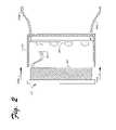
- FIG. 2is a cross-sectional view of an exemplary keypad illustrating installation in a wall box.
- FIG. 3is a cross-sectional diagrammatic view of an exemplary keypad illustrating various layers of the keypad.
- FIG. 4is an illustration of an exemplary sensing surface which may be implemented for a keypad.
- FIG. 5is an illustration of another exemplary sensing surface which may be implemented for a keypad.
- FIG. 6is a high-level schematic diagram of exemplary control circuitry which may be implemented for receiving input from a keypad and generating output for a device operatively associated with the keypad.
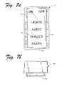
- FIG. 7is a front perspective view of another exemplary embodiment of a keypad with a flat transparent cover, shown as the keypad may be mounted to a wall.
- FIG. 7 ais a front plan view of the exemplary keypad shown in FIG. 7 .
- FIG. 7 bis a top plan view of the exemplary keypad shown in FIG. 7 .
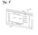
- FIG. 8is a front perspective view of another exemplary embodiment of a keypad with an integrated display device.
- An exemplary keypad devicemay include an optional transparent cover overlaid on a switching element (e.g., a capacitive, resistive, optical matrix, sonic, and/or heat sensitive switching element). Switching fields (or switch locations) may be defined on the switching element using program code, and printed labels may be provided (e.g., between the transparent panel and the switching element or vice versa) to identify the switching fields to a user.
- a switching elemente.g., a capacitive, resistive, optical matrix, sonic, and/or heat sensitive switching element.
- Switching fieldsmay be defined on the switching element using program code, and printed labels may be provided (e.g., between the transparent panel and the switching element or vice versa) to identify the switching fields to a user.
- the usermay select one or more automation functions by touching the transparent panel in an area labeled with one or more functions.
- the switching elementdetects the user's selection (e.g., the switching fields being activated), and control circuitry responds by signaling an automation device to execute the corresponding function.
- Exemplary embodiments of the keypadenable ready integration with other visual displays (e.g., TFT panels), provides a design that integrates with the environment, include a “slim” profile, and have no moving parts.
- the keypadmay also be configured with customized switch layouts. Accordingly, the keypad is easy to use and may be readily customized and changed for individual users.
- FIG. 1is a front perspective view of an exemplary keypad 100 with a convex transparent cover, shown as the keypad may be mounted to a wall 105 .
- FIG. 1 ais a front plan view of the exemplary keypad 100 shown in FIG. 1 .
- FIG. 1 bis a top plan view of the exemplary keypad 100 shown in FIG. 1 .
- Keypad 100may include a sensing surface 110 for receiving input from a user (e.g., when the user touches or presses surface 110 ).
- Sensing surface 110may be implemented as a plurality of switching elements which are configured to detect a user's input (e.g., capacitance resulting from a finger on or near the surface 110 ). Exemplary embodiments of the sensing surface 110 are described in more detail below with reference to FIGS. 4 and 5 .
- Transparent cover 120protects the sensing surface 110 (e.g., from dust, debris, and wear) while still allowing the user to see one or more legend or labels 130 , without inhibiting the ability detect input by the sensing surface 110 .
- Label 130identifies for the user various functions available via the keypad 100 , e.g., by touching the sensing surface 110 .
- different areas of the sensing surface 110may correspond to different functions, as illustrated in FIG. 1 by the labels for Lights, Audio, Shades, and Party.
- Indicator lights 140may be provided to indicate a user's selections.
- indicator light 140 next to the label 130may indicate the shades are open or closed. Openings may be formed through the label 130 so that the light can shine through the label 130 . These openings may be slightly smaller than the lights 140 , allowing for some tolerance in alignment.
- light pipe indicationsmay be provided outside the label area.
- the label 130may serve as a semi-transparent mask over the lights 140 . Such an implementation may enable the light to shine through the label. Different colors provided on the label 130 also enable different color lighting using the same color indicator light (e.g., broad spectrum or white light).
- Backlightingmay also be provided behind the label 130 , e.g., so that the keypad 100 is visible in dark rooms.
- the balance of the labelis clear (or translucent).
- a semi-clear labelmay be implemented to serve as a diffuser for the backlighting.
- the label 130may then be custom printed on a first surface with the desired legends and a continuous background color across its whole width.
- Keypad 100may also be provided with control circuitry for controlling various functions (e.g., building automation devices). Control circuitry is described in more detail below with reference to FIG. 6 . For now, it is enough to understand that the control circuitry may be provided on a circuit board and the sensing surface 110 mounted to it. The entire assembly can then be mounted in the wall 105 , as better illustrated with reference to FIG. 2 .
- FIG. 2is a cross-sectional side plan view of an exemplary keypad 200 (e.g., the keypad 100 in FIG. 1 ) illustrating installation in a wall box 210 .
- the wall box 210may be a standard plastic or metal junction box (or “J-Box”).
- the keypad 200is configured to fit within standard household electrical enclosures and appear similar to other commercially available cover plates (e.g., DECORA® cover plates). It is noted, however, that the keypad 200 is not limited to any particular size or configuration.
- a circuit board 220 including control circuitry and optional backlighting element(s)may be mounted in housing 210 .
- the entire assemblymay in turn be mounted in wall box 210 , as illustrated by arrows 230 a and 230 b.
- the keypad 200may be connected into a building automation system, e.g., via electrical and/or data wiring 240 a and 240 b .
- Keypad 200may include electrical and/or data connections 250 which connect to a controller board 260 (e.g., in the wall box 210 ).
- the controller board 260may be a dimmer control module, such as the dimmer control module described in more detail in U.S. Pat. No. 6,927,546 of Adamson, et al. Dimmer control module may receive input from the keypad 200 and generate a control signal for lighting to adjust the intensity of the lighting.
- keypad 200is not limited to use with any particular type of device (e.g., the dimmer control module). Likewise, the keypad 200 does not need to be connected directly to a controller device. In other embodiments, the keypad 200 may be linked to one or more automation devices indirectly via an automation system (e.g., a CAN bus, Ethernet network, etc.) to control one or more function in the automation system. For purposes of illustration, the keypad 200 may be implemented in a CAN bus building automation system such as the building automation system described in U.S. Patent Publication No. 2004/0176877 of Hesse, et al. However, the keypad 200 is not limited to use in any particular environment.
- an automation systeme.g., a CAN bus, Ethernet network, etc.
- the keypad 200may be implemented in a CAN bus building automation system such as the building automation system described in U.S. Patent Publication No. 2004/0176877 of Hesse, et al.
- the keypad 200is not limited to use in any particular environment.
- FIG. 3is a cross-sectional diagrammatic view of an exemplary keypad 300 illustrating various layers of the keypad 300 .
- Exemplary keypad 300may include a cover 310 , a label 320 , a sensing surface 330 , an adhesive 335 , a structural backing 340 , and a backlight 350 . It is noted that although the various layers are shown substantially in contact with one another, in other embodiments, there may exist airspace between one or more of the layers. It is also noted that the label 320 is not limited to being overlaid on the sensing surface 330 . In other embodiments, the label 320 may be positioned behind the sensing surface 330 .
- the cover 310is manufactured from a transparent or semi-transparent material (e.g., plastic or glass). However, the cover 310 does not need to be transparent or semi-transparent. In other embodiments, the cover 310 may be opaque and the label 320 may be provided over the surface of the cover 310 . Or in another embodiment, the label 320 may be coated (e.g., with a plastic material), thereby serving as a label and protective cover.
- a transparent or semi-transparent materiale.g., plastic or glass
- the cover 310does not need to be transparent or semi-transparent.
- the cover 310may be opaque and the label 320 may be provided over the surface of the cover 310 .
- the label 320may be coated (e.g., with a plastic material), thereby serving as a label and protective cover.
- the label 320may be a paper or plastic label which can be printed on using standard printing devices, such as, e.g., laser or inkjet printers.
- the label 320may also be translucent or semi-translucent.
- Other embodiments of the label 320may include, but are not limited to, die-cut labels and micro-perforated sheets.
- the label 320may also be removable and replaceable, before or after installation, e.g., without having to remove the keypad from the wall box. For example, a user may remove cover 310 to access the label 320 . As mentioned above, the label 320 may also be integrated, or provided as part of the cover 310 .
- the sensing surface 330may be implemented as an indium tin oxide (ITO) surface.
- ITOindium tin oxide
- An ITO surfacemay be sputter-deposited on a thin plastic film to form one or more “hot areas” or a matrix. These hot areas or matrix may be assigned to one or more switching fields and are electrically connected to the control circuitry (e.g., control circuitry 600 shown in FIG. 6 ), which may convert user input on the sensing surface 330 into binary data (e.g., 1's and 0's) for controlling one or more devices and/or functions. Accordingly, if the user touches on or near the sensing surface 330 , an electrical signal is generated indicative of the switching field. The electrical signal is issued to the control circuitry to generate an output signal corresponding to the function labeled on the keypad 300 .
- the sensing surface 330may be calibrated based on the thickness of the cover 310 and label 320 so that input can be detected through the layers, optionally even if the user is wearing gloves.
- the sensing surface 330is self-calibrating, e.g., based on user input over time.
- An optional pressure-sensitive adhesive layer 335may be provided, e.g., integral with the structural backing 340 .
- Any suitable adhesive layer 330may be used.
- the adhesive layer 335may be a tacky adhesive, such as the type of adhesive used on POST-IT or “sticky” notes.
- Adhesive layer 335serves to attach the sensing surface 330 to the structural backing 340 . It is noted that adhesive may also be provided between one or more of the other layers shown in FIG. 3 .
- the backlight 350may include one or more light-emitting diodes (LEDs). It is noted, however, that the keypad 300 is not limited to use with LED backlighting. In other implementations, LED fiber optics may be used, as may an electro-luminescent panel.
- LEDslight-emitting diodes
- the backlight 350may be operatively associated with a photo sensor that controls the backlight 350 and intensity of the backlight 350 . Accordingly, the backlight 350 may be responsive to external or ambient lighting, e.g., the intensity of light from the backlight 350 may decrease with decreasing ambient light and increase with increasing ambient light. In addition, the backlight 350 may be programmed by the user (e.g., for the minimum and maximum illumination levels).
- FIG. 4is an illustration of an exemplary sensing surface 400 which may be implemented for a keypad (e.g., the keypad 100 shown in FIG. 1 ).
- Exemplary sensing surface 400may include switch labels (e.g., the switch label 410 ) and corresponding switching elements (e.g., switching element 420 shown by dashed lines around switch label 410 ).
- the switching elements 420are “hot areas” or sensing locations on the sensing surface 400 for receiving user input.
- switching elements 420may be implemented for detecting capacitive input on the sensing surface.
- the capacitive surfaceresponds to a change in capacitance caused by a change in the dielectric, namely the air space between the ITO traces on the substrate.
- the sensing surfaceresponds to the presence of a finger (or other object), even without physical contact on the sensing surface.
- labelsmay be positioned between the sensing surface and the object (e.g., the user's finger) and when the object is on or near the paper, it still causes a control signal.
- the keypadis not limited to a capacitive sensing surface.
- Other exemplary embodimentsmay include thermal sensing, and/or resistive sensing switching elements, to name only a few examples.
- the switching elements 420may be electrically connected to control circuitry for implementing the functions corresponding to the labels 410 .
- the sensing surface 400is not limited to any particular type or duration of touch.
- the sensing surface 400may be implemented to detect any of a wide variety of input, including but not limited to, a finger, stylus, and/or other object.
- the sensing surface 400may be implemented as a secure surface for particular implementations (e.g., a security system). Such an embodiment may require detection of the user's fingerprint in order to activate the sensing surface.
- the sensing surface 400may include “dead spots.” For example, if the user were to touch an area as illustrated by oval 430 , nothing would happen. While this may be desirable in some implementations, in other embodiments, the sensing surface 400 may detect adjacent touch without the user having to physically touch the switching elements 420 .
- the switching elements 420may be extended beyond the label to reduce or altogether eliminate dead spots, e.g., as shown by switching element 425 surrounding label 415 .
- switching element 425surrounding label 415 .
- FIG. 4if the user were to touch an area as illustrated by oval 440 , it would be detected by switching element 425 to activate the function corresponding to label 415 .
- Still other embodimentsare also contemplated, such as the embodiment described in more detail below with reference to FIG. 5 .
- FIG. 5is an illustration of another exemplary sensing surface 500 which may be implemented for a keypad (e.g., the keypad 100 shown in FIG. 1 ).
- Exemplary sensing surface 500may include switch labels (e.g., the switch label 510 ).
- the sensing surface 500includes a switching grid 520 including a plurality of grid elements (e.g., the grid element 530 ).
- the switching grid 520has a sensing resolution of 253 by 253 (or 64,009 grid elements 530 ).
- the sensing surface 500is not limited to any particular resolution. The resolution may depend on a number of considerations including, but not limited to, user preferences and design considerations.
- the capacitance generated by touching the grid elements 530is measured, and an electrical signal delivers the capacitance to control circuitry for determining the position of touch (e.g., X, Y coordinates).
- the grid elementsmay be positioned such that there are no dead spots, and anywhere a user touches is detected (e.g., in oval 540 between labels 510 and 515 ).
- a user touchese.g., in oval 540 between labels 510 and 515 .
- Such an embodimentenables the use of any of a wide variety of different type, shape, and/or position of labels on the sensing surface 500 , e.g., as illustrated by the labels shown in FIG. 5 .
- sensing surface 500is not limited to any particular type of detection mechanism.
- Other exemplary embodimentsmay include, thermal sensing, and/or resistive-sensing switching elements.
- FIG. 6is a high-level schematic diagram of exemplary control circuitry 600 which may be implemented for receiving input from a keypad (e.g., the keypad 100 in FIG. 1 ) and generating output for a device (e.g., the controller board 260 in FIG. 2 ) operatively associated with the keypad.
- Control circuitry 600may be implemented, e.g., as one or more integrated circuit mounted to a circuit board 605 .
- Control circuitry 600may include a coordinate processor 610 which receives input 615 from the keypad.
- input 615 from the keypadmay include electronic signal(s) corresponding to a user's touch.
- Coordinate processor 610outputs a grid space or X, Y coordinates corresponding to the user's touch.
- a control processor 620 operatively associated with the coordinate process 610receives the X, Y coordinates (or other suitable data indicative of the user's touch) and determines a function indicative of the user's touch (e.g., a user selection).
- the touch spacemay be interpolated if two fingers are on the surface at the same time.
- control processor 620accesses cell definitions 630 and instruction data store 635 from memory 640 .
- Cell definitions 630may be implemented, e.g., as one or more data structure identifying functions corresponding to the X, Y coordinates where the user has touched the keypad.
- Instruction data store 635may also be implemented, e.g., as one or more data structure including control instructions for executing the functions.
- a usermay touch the keypad in an area labeled with an arrow for increasing lighting in a room.
- One or more electrical signalsare generated at the sensing surface and issued to the coordinate processor 610 .
- Coordinate processor 610receives the electrical signal(s) and may generate an X, Y coordinate (5, 10).
- Control processorreceives the X, Y coordinate (5, 10) and accesses memory 640 to determine which function(s) the X, Y coordinate (5, 10) corresponds to. In this example, the X, Y coordinate (5, 10) corresponds to the function “increase lighting.”
- the control processor 620then accesses the instruction data store 635 and generates output 650 for increasing the lighting (e.g., a signal including control instructions).
- the outputmay be issued to one or more automation device (e.g., the controller board 260 in FIG. 2 ) to increase lighting in the room.
- control circuitry 600may also be implemented to configure (or reconfigure) the keypad.
- a usermay operate the same switching field (or “key”) on the keypad to program one or more of the switching fields for one or more functions.
- the usermay press a program “key” to enter a programming mode, and then select from various pre-programmed devices or functions to configure one or more switching field.
- the usermay program the keypad using a personal computer (PC), personal digital assistant (PDA), etc. to define new functions and/or sensing areas of the keypad in program code.
- the usermay also program the luminance of the status LEDs and/or backlighting using similar techniques.
- control circuitry 600may include a remote access point 660 to enable an external remote control (e.g., infrared, BLUETOOTH®, Internet connection, etc.) allowing control and/or programming the keypad without touching it.
- an audible and/or kinetic indicator(not shown) may be provided for tactile feedback (e.g., sounding “beeps” or vibrating when the user touches designated areas of the sensing surface) to enhance the perceived switching action for the user.
- the usermay also program the level of the audible and/or kinetic indicator (e.g., using the techniques described above).
- Other input sensorsmay also be provided, such as, e.g., radio frequency (RF), light, and temperature, to name only a few examples.
- RFradio frequency
- FIG. 7is a front perspective view of another exemplary embodiment of a keypad 700 with a flat transparent cover, shown as the keypad may be mounted to a wall 705 .
- FIG. 7 ais a front plan view of the exemplary keypad 700 shown in FIG. 7 .
- FIG. 7 bis a top plan view of the exemplary keypad 700 shown in FIG. 7 .
- 700-series reference numbersare used to refer to corresponding elements in the embodiment of keypad 100 shown and described above with reference to FIGS. 1 , 1 a , and 1 b , and may not be described again with reference to FIGS. 7 , 7 a , and 7 b.
- Keypad 700may include a sensing surface 710 for receiving input from a user (e.g., when the user touches or presses the surface 710 ). Sensing surface 710 may be overlaid by a lens or transparent cover 720 . Label 730 identifies for the user various functions available via the keypad 700 .
- the transparent cover 720is flat.
- the transparent cover 720may be mounted such that it is flush with the wall 705 .
- the transparent cover 720may stick out from the wall, e.g., such as a conventional light switch plate.
- FIG. 8is a front perspective view of another exemplary embodiment of a keypad 800 with an integrated display device.
- the display deviceis a thin film transistor (TFT) display device 810 , although other display devices now known or later developed may also be implemented.
- Keypad 800includes a switch portion 820 adjacent the TFT device 810 . In this embodiment, the user may interface with functions provided by the switch portion 820 even if the TFT device 810 is turned off or in a hibernate mode.
- TFTthin film transistor
- the keypad 800is still operable, e.g., to turn on the lights when a user enters a darkened room because the user is still able to access the keypad functionality (e.g., lighting controls) provided in the switch portion 820 even if the TFT device 810 remains inactive.
- the keypad functionalitye.g., lighting controls
- Switch portion 820may be implemented, e.g., as an ITO deposition layer which forms an array of switch elements on a panel adjacent the TFT device. As discussed above (e.g., with reference to FIGS. 4 and 5 ), this array implements a software-defined sensing area where custom printed labels may be applied. Optionally, indicator lights (e.g., the LED 825 ) and/or backlighting may also be provided as described above.
- the keypad 800may also include an active border 830 surrounding the TFT device 810 , and/or covering the TFT display.
- a transparent panel including the ITO deposition layermay be provided over the active border 830 and/or the TFT display itself.
- the transparent panelmay also be provided over the switch portion 820 to enable switching via the switch portion 820 .
- the TFT device 810may be implemented to display functions (and/or programming options), and the user may interact with the keypad 800 as indicated by the labels in switch portion 820 and/or by touching the active border 830 and/or TFT display as indicated by output on the TFT display.
- the displayneed not be a TFT device.
- the displaymay also include organic LED, electronic paper technologies, or other types of graphical or visual display devices now known or later developed.
Landscapes
- Engineering & Computer Science (AREA)
- General Engineering & Computer Science (AREA)
- Physics & Mathematics (AREA)
- General Physics & Mathematics (AREA)
- Automation & Control Theory (AREA)
- Input From Keyboards Or The Like (AREA)
Abstract
Description
Claims (25)
Priority Applications (1)
| Application Number | Priority Date | Filing Date | Title |
|---|---|---|---|
| US11/273,864US7394367B1 (en) | 2004-11-16 | 2005-11-15 | Keypad for building automation |
Applications Claiming Priority (3)
| Application Number | Priority Date | Filing Date | Title |
|---|---|---|---|
| US62814204P | 2004-11-16 | 2004-11-16 | |
| US71341705P | 2005-09-01 | 2005-09-01 | |
| US11/273,864US7394367B1 (en) | 2004-11-16 | 2005-11-15 | Keypad for building automation |
Publications (1)
| Publication Number | Publication Date |
|---|---|
| US7394367B1true US7394367B1 (en) | 2008-07-01 |
Family
ID=39561139
Family Applications (1)
| Application Number | Title | Priority Date | Filing Date |
|---|---|---|---|
| US11/273,864Expired - Fee RelatedUS7394367B1 (en) | 2004-11-16 | 2005-11-15 | Keypad for building automation |
Country Status (1)
| Country | Link |
|---|---|
| US (1) | US7394367B1 (en) |
Cited By (24)
| Publication number | Priority date | Publication date | Assignee | Title |
|---|---|---|---|---|
| US20080012734A1 (en)* | 2006-07-12 | 2008-01-17 | Dominique Ciechanowski | Interface system for tubs |
| US20080055265A1 (en)* | 2006-08-30 | 2008-03-06 | Elan Home Systems, Llc | Interactive touchpad |
| US20090213698A1 (en)* | 2008-02-26 | 2009-08-27 | Leviton Manufacturing Company, Inc. | Wall mounted programmable timer system |
| US20100039240A1 (en)* | 2008-08-15 | 2010-02-18 | Wayne-Dalton Corp. | Method for Wiring Devices in a Structure Using a Wireless Network |
| US20100097781A1 (en)* | 2008-10-16 | 2010-04-22 | Combs Jeffrey S | System for light switch identification |
| US20100236824A1 (en)* | 2008-04-21 | 2010-09-23 | Inncom International Inc. | Smart wall box |
| US20110199495A1 (en)* | 2010-02-12 | 2011-08-18 | Honeywell International Inc. | Method of manipulating assets shown on a touch-sensitive display |
| US20110199516A1 (en)* | 2010-02-12 | 2011-08-18 | Honeywell International Inc. | Method of showing video on a touch-sensitive display |
| US20110199314A1 (en)* | 2010-02-12 | 2011-08-18 | Honeywell International Inc. | Gestures on a touch-sensitive display |
| US20110199517A1 (en)* | 2010-02-12 | 2011-08-18 | Honeywell International Inc. | Method of showing video on a touch-sensitive display |
| US20110199386A1 (en)* | 2010-02-12 | 2011-08-18 | Honeywell International Inc. | Overlay feature to provide user assistance in a multi-touch interactive display environment |
| US20110203865A1 (en)* | 2010-02-22 | 2011-08-25 | Shur Company | Wireless controllers |
| US20110292663A1 (en)* | 2010-05-26 | 2011-12-01 | Doug Fredrickson | Non-Opaque Junction Box Cover With Troubleshooting Electronic Circuit Board |
| US20120253521A1 (en)* | 2011-03-31 | 2012-10-04 | Trane International Inc. | Systems and Methods For Controlling Multiple HVAC Systems |
| US20120265369A1 (en)* | 2010-02-22 | 2012-10-18 | Shur-Co, Llc | Wireless controller system |
| GB2492350A (en)* | 2011-06-28 | 2013-01-02 | King I Electromechanical Ind Co Ltd | A touch switch with a backlight that is programmable in colour and intensity |
| US8836802B2 (en) | 2011-03-21 | 2014-09-16 | Honeywell International Inc. | Method of defining camera scan movements using gestures |
| US20150002276A1 (en)* | 2013-06-26 | 2015-01-01 | Savant Systems, Llc | Lighting controller |
| US9747026B1 (en) | 2006-05-25 | 2017-08-29 | Creator Technology B.V. | Low pin count solution using capacitance sensing matrix for keyboard architecture |
| US20180116754A1 (en)* | 2016-11-01 | 2018-05-03 | American Sterilizer Company | Lighthead identification system for lighthead control |
| US10379665B1 (en) | 2018-01-29 | 2019-08-13 | Crestron Electronics, Inc. | Control panel assembly |
| US10796870B2 (en) | 2012-11-20 | 2020-10-06 | Pass & Seymour, Inc. | Electronic switching device and system |
| GB2590577A (en)* | 2015-03-24 | 2021-06-30 | Axxess Ind Inc | Modular load control |
| USD1068693S1 (en)* | 2023-07-31 | 2025-04-01 | Ningbo Litesun Electric Co., Ltd. | Wall plate |
Citations (33)
| Publication number | Priority date | Publication date | Assignee | Title |
|---|---|---|---|---|
| US4158432A (en)* | 1976-12-10 | 1979-06-19 | Texas Instruments Incorporated | Control of self-test feature for appliances or electronic equipment operated by microprocessor |
| US4447692A (en)* | 1981-05-18 | 1984-05-08 | Essex Group, Inc. | Control system with interactive display |
| USD327471S (en) | 1989-08-22 | 1992-06-30 | Burle Technologies, Inc. | Infra-red detector wall switch |
| US5128654A (en) | 1990-02-23 | 1992-07-07 | Lightolier Incorporated | Preset light controller including infrared sensor operable in multiple modes |
| USD343386S (en) | 1992-01-28 | 1994-01-18 | The Watt Stopper | Motion detection wall switch |
| USD376130S (en) | 1995-04-20 | 1996-12-03 | Novitas Incorporated | Ultrasonic wall switch |
| USD377789S (en) | 1995-07-17 | 1997-02-04 | Primax Electronics, Ltd. | Touch pad |
| USD380202S (en) | 1995-11-13 | 1997-06-24 | Texas Microsystems, Inc. | Hand-held computer |
| USD380452S (en) | 1995-07-13 | 1997-07-01 | The Watt Stopper | Wall-mounted switch |
| USD380737S (en) | 1995-09-25 | 1997-07-08 | Michael Paul Weir | Electronic control module display |
| EP0813328A2 (en)* | 1996-06-13 | 1997-12-17 | Nokia Mobile Phones Ltd. | Touch screen keyboard |
| USD390211S (en) | 1997-03-19 | 1998-02-03 | Interlink Electronics, Inc. | Combined computer control and touch pad |
| USD392947S (en) | 1996-08-02 | 1998-03-31 | Kabushiki Kaisha Toshiba | Electronic computer |
| US5739753A (en) | 1996-09-19 | 1998-04-14 | Leviton Manufacturing Co., Inc. | Detector system with adjustable field of view |
| USD398905S (en) | 1997-09-25 | 1998-09-29 | Lance R Bergenham | Video book |
| USD409505S (en) | 1997-03-18 | 1999-05-11 | Intermatic Incorporated | Front housing for an electronic timer |
| USD412897S (en) | 1998-09-22 | 1999-08-17 | Ingersoll-Rand Company | Housing enclosure for a microprocessor controller |
| US5946209A (en) | 1995-02-02 | 1999-08-31 | Hubbell Incorporated | Motion sensing system with adaptive timing for controlling lighting fixtures |
| US6046730A (en)* | 1996-03-15 | 2000-04-04 | At&T Corp | Backlighting scheme for a multimedia terminal keypad |
| USD422971S (en) | 1998-06-27 | 2000-04-18 | Wella Aktiengesellschaft | Control for input and output of data for use in hairdressing |
| US6121889A (en) | 1997-04-24 | 2000-09-19 | Intermatic Incorporated | In-wall electronic timer |
| USD435798S1 (en) | 1999-12-08 | 2001-01-02 | Mytech | Ultrasonic occupancy sensor |
| USD455406S1 (en) | 2000-12-13 | 2002-04-09 | Sharper Image Corporation | Automatic light controller with sound and motion activation |
| US20020135476A1 (en) | 2001-01-31 | 2002-09-26 | Mckinney Edward C. | Sound and motion activated light controller |
| USD467557S1 (en) | 1999-12-29 | 2002-12-24 | Leviton Manufacturing Co., Inc. | Combined dimmer, switch, IR receiver and thermostat |
| US6581846B1 (en) | 2002-03-06 | 2003-06-24 | Howard B. Rosen | Thermostat including a vacation mode in which electrical devices within and proximate the conditioned space are operated by the thermostat to provide an occupied appearance |
| USD480722S1 (en) | 2001-12-21 | 2003-10-14 | Research In Motion Limited | Handheld electronic device and a keypad |
| US6750407B2 (en) | 2001-06-22 | 2004-06-15 | Lg Electronics Inc. | Control panel assembly for home appliances and method for manufacturing the same |
| USD494585S1 (en) | 2003-08-29 | 2004-08-17 | Colorado Vnet | Keypad and keypad housing |
| US6850159B1 (en) | 2001-05-15 | 2005-02-01 | Brian P. Platner | Self-powered long-life occupancy sensors and sensor circuits |
| USD502466S1 (en) | 2004-02-27 | 2005-03-01 | Colorado Vnet, Llc | Keypad and keypad housing |
| US20060114245A1 (en)* | 2004-12-01 | 2006-06-01 | Masters Timothy E | Touch screen cover |
| USD538234S1 (en) | 2005-09-01 | 2007-03-13 | Colorado Vnet, Llc | Transparent keypad and keypad housing |
- 2005
- 2005-11-15USUS11/273,864patent/US7394367B1/ennot_activeExpired - Fee Related
Patent Citations (33)
| Publication number | Priority date | Publication date | Assignee | Title |
|---|---|---|---|---|
| US4158432A (en)* | 1976-12-10 | 1979-06-19 | Texas Instruments Incorporated | Control of self-test feature for appliances or electronic equipment operated by microprocessor |
| US4447692A (en)* | 1981-05-18 | 1984-05-08 | Essex Group, Inc. | Control system with interactive display |
| USD327471S (en) | 1989-08-22 | 1992-06-30 | Burle Technologies, Inc. | Infra-red detector wall switch |
| US5128654A (en) | 1990-02-23 | 1992-07-07 | Lightolier Incorporated | Preset light controller including infrared sensor operable in multiple modes |
| USD343386S (en) | 1992-01-28 | 1994-01-18 | The Watt Stopper | Motion detection wall switch |
| US5946209A (en) | 1995-02-02 | 1999-08-31 | Hubbell Incorporated | Motion sensing system with adaptive timing for controlling lighting fixtures |
| USD376130S (en) | 1995-04-20 | 1996-12-03 | Novitas Incorporated | Ultrasonic wall switch |
| USD380452S (en) | 1995-07-13 | 1997-07-01 | The Watt Stopper | Wall-mounted switch |
| USD377789S (en) | 1995-07-17 | 1997-02-04 | Primax Electronics, Ltd. | Touch pad |
| USD380737S (en) | 1995-09-25 | 1997-07-08 | Michael Paul Weir | Electronic control module display |
| USD380202S (en) | 1995-11-13 | 1997-06-24 | Texas Microsystems, Inc. | Hand-held computer |
| US6046730A (en)* | 1996-03-15 | 2000-04-04 | At&T Corp | Backlighting scheme for a multimedia terminal keypad |
| EP0813328A2 (en)* | 1996-06-13 | 1997-12-17 | Nokia Mobile Phones Ltd. | Touch screen keyboard |
| USD392947S (en) | 1996-08-02 | 1998-03-31 | Kabushiki Kaisha Toshiba | Electronic computer |
| US5739753A (en) | 1996-09-19 | 1998-04-14 | Leviton Manufacturing Co., Inc. | Detector system with adjustable field of view |
| USD409505S (en) | 1997-03-18 | 1999-05-11 | Intermatic Incorporated | Front housing for an electronic timer |
| USD390211S (en) | 1997-03-19 | 1998-02-03 | Interlink Electronics, Inc. | Combined computer control and touch pad |
| US6121889A (en) | 1997-04-24 | 2000-09-19 | Intermatic Incorporated | In-wall electronic timer |
| USD398905S (en) | 1997-09-25 | 1998-09-29 | Lance R Bergenham | Video book |
| USD422971S (en) | 1998-06-27 | 2000-04-18 | Wella Aktiengesellschaft | Control for input and output of data for use in hairdressing |
| USD412897S (en) | 1998-09-22 | 1999-08-17 | Ingersoll-Rand Company | Housing enclosure for a microprocessor controller |
| USD435798S1 (en) | 1999-12-08 | 2001-01-02 | Mytech | Ultrasonic occupancy sensor |
| USD467557S1 (en) | 1999-12-29 | 2002-12-24 | Leviton Manufacturing Co., Inc. | Combined dimmer, switch, IR receiver and thermostat |
| USD455406S1 (en) | 2000-12-13 | 2002-04-09 | Sharper Image Corporation | Automatic light controller with sound and motion activation |
| US20020135476A1 (en) | 2001-01-31 | 2002-09-26 | Mckinney Edward C. | Sound and motion activated light controller |
| US6850159B1 (en) | 2001-05-15 | 2005-02-01 | Brian P. Platner | Self-powered long-life occupancy sensors and sensor circuits |
| US6750407B2 (en) | 2001-06-22 | 2004-06-15 | Lg Electronics Inc. | Control panel assembly for home appliances and method for manufacturing the same |
| USD480722S1 (en) | 2001-12-21 | 2003-10-14 | Research In Motion Limited | Handheld electronic device and a keypad |
| US6581846B1 (en) | 2002-03-06 | 2003-06-24 | Howard B. Rosen | Thermostat including a vacation mode in which electrical devices within and proximate the conditioned space are operated by the thermostat to provide an occupied appearance |
| USD494585S1 (en) | 2003-08-29 | 2004-08-17 | Colorado Vnet | Keypad and keypad housing |
| USD502466S1 (en) | 2004-02-27 | 2005-03-01 | Colorado Vnet, Llc | Keypad and keypad housing |
| US20060114245A1 (en)* | 2004-12-01 | 2006-06-01 | Masters Timothy E | Touch screen cover |
| USD538234S1 (en) | 2005-09-01 | 2007-03-13 | Colorado Vnet, Llc | Transparent keypad and keypad housing |
Non-Patent Citations (5)
| Title |
|---|
| "RCS: KPG8 Multi Menu Keypad and KPL-7 7-Button Keypad," (2002), 2 pages, Residential Control Systems, Inc., Rancho Cordova, CA. |
| AMX, Welcome to the AMX New Products, www.amx.com/new-products-public.asp, 12 pages, copyright 2005 AMX Corporation. |
| U.S. PTO Office Action issued Dec. 28, 2006 in U.S. Appl. No. 10/793,596, 13 pages. |
| www.matsci.com/content.html; 1 page printed from Internet on Oct. 20, 2004 (re-printed on Aug. 24, 2006). |
| www.merten.de/html/en/1163.html; 2 pages printed from Internet on Oct. 29, 2004 (re-printed on Aug. 24, 2006). |
Cited By (40)
| Publication number | Priority date | Publication date | Assignee | Title |
|---|---|---|---|---|
| US9747026B1 (en) | 2006-05-25 | 2017-08-29 | Creator Technology B.V. | Low pin count solution using capacitance sensing matrix for keyboard architecture |
| US20080012734A1 (en)* | 2006-07-12 | 2008-01-17 | Dominique Ciechanowski | Interface system for tubs |
| US9114060B2 (en)* | 2006-07-12 | 2015-08-25 | C.G. Air Systemes Inc. | Interface system for tubs |
| US7847790B2 (en)* | 2006-08-30 | 2010-12-07 | Elan Home Systems | Interactive touchpad |
| US20080055265A1 (en)* | 2006-08-30 | 2008-03-06 | Elan Home Systems, Llc | Interactive touchpad |
| US8050145B2 (en)* | 2008-02-26 | 2011-11-01 | Leviton Manufacturing Co., Inc. | Wall mounted programmable timer system |
| US10048653B2 (en) | 2008-02-26 | 2018-08-14 | Leviton Manufacturing Company, Inc. | Wall mounted programmable timer system |
| US20090213698A1 (en)* | 2008-02-26 | 2009-08-27 | Leviton Manufacturing Company, Inc. | Wall mounted programmable timer system |
| US20100236824A1 (en)* | 2008-04-21 | 2010-09-23 | Inncom International Inc. | Smart wall box |
| US20100039240A1 (en)* | 2008-08-15 | 2010-02-18 | Wayne-Dalton Corp. | Method for Wiring Devices in a Structure Using a Wireless Network |
| US8598993B2 (en)* | 2008-08-15 | 2013-12-03 | Homerun Holdings Corporation | Method for wiring devices in a structure using a wireless network |
| US20100097781A1 (en)* | 2008-10-16 | 2010-04-22 | Combs Jeffrey S | System for light switch identification |
| US8205996B2 (en)* | 2008-10-16 | 2012-06-26 | Combs Jeffrey S | System for light switch identification |
| US20110199517A1 (en)* | 2010-02-12 | 2011-08-18 | Honeywell International Inc. | Method of showing video on a touch-sensitive display |
| US20110199314A1 (en)* | 2010-02-12 | 2011-08-18 | Honeywell International Inc. | Gestures on a touch-sensitive display |
| US20110199495A1 (en)* | 2010-02-12 | 2011-08-18 | Honeywell International Inc. | Method of manipulating assets shown on a touch-sensitive display |
| US20110199516A1 (en)* | 2010-02-12 | 2011-08-18 | Honeywell International Inc. | Method of showing video on a touch-sensitive display |
| US8638371B2 (en) | 2010-02-12 | 2014-01-28 | Honeywell International Inc. | Method of manipulating assets shown on a touch-sensitive display |
| US20110199386A1 (en)* | 2010-02-12 | 2011-08-18 | Honeywell International Inc. | Overlay feature to provide user assistance in a multi-touch interactive display environment |
| US8570286B2 (en) | 2010-02-12 | 2013-10-29 | Honeywell International Inc. | Gestures on a touch-sensitive display |
| US9847797B2 (en)* | 2010-02-22 | 2017-12-19 | Shur-Co, Llc | Wireless controllers |
| US20120265369A1 (en)* | 2010-02-22 | 2012-10-18 | Shur-Co, Llc | Wireless controller system |
| US20110203865A1 (en)* | 2010-02-22 | 2011-08-25 | Shur Company | Wireless controllers |
| US9716518B2 (en) | 2010-02-22 | 2017-07-25 | Shur-Co, Llc | Wireless controller system |
| US9088311B2 (en)* | 2010-02-22 | 2015-07-21 | Shur-Co, Llc | Wireless controller system |
| US20110292663A1 (en)* | 2010-05-26 | 2011-12-01 | Doug Fredrickson | Non-Opaque Junction Box Cover With Troubleshooting Electronic Circuit Board |
| US8764211B2 (en)* | 2010-05-26 | 2014-07-01 | Doug Fredrickson | Non-opaque junction box cover with troubleshooting electronic circuit board |
| US8836802B2 (en) | 2011-03-21 | 2014-09-16 | Honeywell International Inc. | Method of defining camera scan movements using gestures |
| US20120253521A1 (en)* | 2011-03-31 | 2012-10-04 | Trane International Inc. | Systems and Methods For Controlling Multiple HVAC Systems |
| US9494952B2 (en)* | 2011-03-31 | 2016-11-15 | Trane International Inc. | Systems and methods for controlling multiple HVAC systems |
| GB2492350B (en)* | 2011-06-28 | 2018-07-11 | King I Electromechanical Ind Co Ltd | A touch lamp switch |
| GB2492350A (en)* | 2011-06-28 | 2013-01-02 | King I Electromechanical Ind Co Ltd | A touch switch with a backlight that is programmable in colour and intensity |
| US10796870B2 (en) | 2012-11-20 | 2020-10-06 | Pass & Seymour, Inc. | Electronic switching device and system |
| US20150002276A1 (en)* | 2013-06-26 | 2015-01-01 | Savant Systems, Llc | Lighting controller |
| US9867260B2 (en)* | 2013-06-26 | 2018-01-09 | Savant Systems, Llc | Lighting controller |
| GB2590577A (en)* | 2015-03-24 | 2021-06-30 | Axxess Ind Inc | Modular load control |
| US20180116754A1 (en)* | 2016-11-01 | 2018-05-03 | American Sterilizer Company | Lighthead identification system for lighthead control |
| US10603132B2 (en)* | 2016-11-01 | 2020-03-31 | American Sterilizer Company | Lighthead identification system for lighthead control |
| US10379665B1 (en) | 2018-01-29 | 2019-08-13 | Crestron Electronics, Inc. | Control panel assembly |
| USD1068693S1 (en)* | 2023-07-31 | 2025-04-01 | Ningbo Litesun Electric Co., Ltd. | Wall plate |
Similar Documents
| Publication | Publication Date | Title |
|---|---|---|
| US7394367B1 (en) | Keypad for building automation | |
| TWI629637B (en) | Controller interface, method of guiding or interfacing a controller interface associated with a controlled device, touch panel control interface, and controller | |
| CN101751176B (en) | Illuminated touchpad module | |
| CN102687103B (en) | Electro-optic display with touch sensor | |
| US7923654B2 (en) | Capacitive touch switch and domestic appliance provided with such switch | |
| US8558799B2 (en) | Method and device for user interaction | |
| KR101440708B1 (en) | Apparatuses, methods, and systems for an electronic device with a detachable user input attachment | |
| US20130093684A1 (en) | Touch keypad module | |
| CN101636710A (en) | The adaptable user interface and the mechanism that are used for portable electric appts | |
| US20110032207A1 (en) | Capacitive touch sensor | |
| US8102081B2 (en) | Electronic apparatus | |
| JP2002366304A (en) | Coordinate input device | |
| CN101622589A (en) | The adaptable user interface and the mechanism that are used for portable electric appts | |
| GB2439554A (en) | Display or keyboard having touch sensitive regions and able to detect simultaneous touches on different regions | |
| US20210141483A1 (en) | Touch encoder, touch panel, and input method editor with integrated development environment and methods thereof | |
| US11662833B2 (en) | Input or control device with variable controls configuration | |
| CN101622590A (en) | The adaptable user interface and the mechanism that are used for portable electric appts | |
| US20160048292A1 (en) | Touch-sensitive control device | |
| CN109474267A (en) | A kind of metal touch control keyboard and preparation method thereof | |
| KR100895147B1 (en) | Refrigerator | |
| KR100772676B1 (en) | Transparent touch switch | |
| US20170364201A1 (en) | Touch-sensitive remote control | |
| JP2011154563A (en) | Keyboard device and electronic apparatus using the same | |
| CN221175024U (en) | Backlight device and multimedia backlight touch system comprising same | |
| KR100985406B1 (en) | Capacitive Touch Panel |
Legal Events
| Date | Code | Title | Description |
|---|---|---|---|
| AS | Assignment | Owner name:COLORADO VNET, LLC, COLORADO Free format text:ASSIGNMENT OF ASSIGNORS INTEREST;ASSIGNORS:AUPPERLE, DONALD P.;BEIERWALTES, WILLIAM T.;ADAMSON, HUGH P.;AND OTHERS;REEL/FRAME:016954/0875;SIGNING DATES FROM 20051114 TO 20051115 | |
| STCF | Information on status: patent grant | Free format text:PATENTED CASE | |
| FEPP | Fee payment procedure | Free format text:PAYER NUMBER DE-ASSIGNED (ORIGINAL EVENT CODE: RMPN); ENTITY STATUS OF PATENT OWNER: LARGE ENTITY Free format text:PAYOR NUMBER ASSIGNED (ORIGINAL EVENT CODE: ASPN); ENTITY STATUS OF PATENT OWNER: LARGE ENTITY | |
| AS | Assignment | Owner name:RUSSOUND ACQUISITION CORP., NEW HAMPSHIRE Free format text:ASSIGNMENT OF ASSIGNORS INTEREST;ASSIGNOR:COLORADO VNET, LLC;REEL/FRAME:024823/0476 Effective date:20100806 | |
| AS | Assignment | Owner name:COLORADO VNET CORP., NEW HAMPSHIRE Free format text:CHANGE OF NAME;ASSIGNOR:RUSSOUND ACQUISITION CORP.;REEL/FRAME:024933/0412 Effective date:20091015 | |
| FEPP | Fee payment procedure | Free format text:PAYER NUMBER DE-ASSIGNED (ORIGINAL EVENT CODE: RMPN); ENTITY STATUS OF PATENT OWNER: LARGE ENTITY | |
| FPAY | Fee payment | Year of fee payment:4 | |
| AS | Assignment | Owner name:3VNET, INC., FLORIDA Free format text:CHANGE OF NAME;ASSIGNOR:COLORADO VNET CORP;REEL/FRAME:030111/0296 Effective date:20120503 | |
| AS | Assignment | Owner name:AUTOMATED CONTROL TECHNOLOGY PARTNERS, INC., FLORI Free format text:ASSIGNMENT OF ASSIGNORS INTEREST;ASSIGNOR:3VNET,INC.;REEL/FRAME:030460/0468 Effective date:20130515 | |
| AS | Assignment | Owner name:GOOGLE INC., CALIFORNIA Free format text:ASSIGNMENT OF ASSIGNORS INTEREST;ASSIGNOR:AUTOMATED CONTROL TECHNOLOGY PARTNERS, INC.;REEL/FRAME:031515/0743 Effective date:20130819 | |
| FEPP | Fee payment procedure | Free format text:PAT HOLDER NO LONGER CLAIMS SMALL ENTITY STATUS, ENTITY STATUS SET TO UNDISCOUNTED (ORIGINAL EVENT CODE: STOL); ENTITY STATUS OF PATENT OWNER: LARGE ENTITY | |
| FPAY | Fee payment | Year of fee payment:8 | |
| AS | Assignment | Owner name:GOOGLE LLC, CALIFORNIA Free format text:CHANGE OF NAME;ASSIGNOR:GOOGLE INC.;REEL/FRAME:044101/0610 Effective date:20170929 | |
| FEPP | Fee payment procedure | Free format text:MAINTENANCE FEE REMINDER MAILED (ORIGINAL EVENT CODE: REM.); ENTITY STATUS OF PATENT OWNER: LARGE ENTITY | |
| LAPS | Lapse for failure to pay maintenance fees | Free format text:PATENT EXPIRED FOR FAILURE TO PAY MAINTENANCE FEES (ORIGINAL EVENT CODE: EXP.); ENTITY STATUS OF PATENT OWNER: LARGE ENTITY | |
| STCH | Information on status: patent discontinuation | Free format text:PATENT EXPIRED DUE TO NONPAYMENT OF MAINTENANCE FEES UNDER 37 CFR 1.362 | |
| FP | Lapsed due to failure to pay maintenance fee | Effective date:20200701 |