US7394347B2 - Locking device for electronic equipment - Google Patents
Locking device for electronic equipmentDownload PDFInfo
- Publication number
- US7394347B2 US7394347B2US10/339,711US33971103AUS7394347B2US 7394347 B2US7394347 B2US 7394347B2US 33971103 AUS33971103 AUS 33971103AUS 7394347 B2US7394347 B2US 7394347B2
- Authority
- US
- United States
- Prior art keywords
- user
- programmable
- control system
- period
- mode
- Prior art date
- Legal status (The legal status is an assumption and is not a legal conclusion. Google has not performed a legal analysis and makes no representation as to the accuracy of the status listed.)
- Expired - Fee Related, expires
Links
- 230000004913activationEffects0.000claimsabstractdescription43
- 230000036961partial effectEffects0.000claimsabstractdescription19
- 230000006870functionEffects0.000claimsdescription8
- 230000003111delayed effectEffects0.000claimsdescription5
- 238000004891communicationMethods0.000claimsdescription3
- 230000009849deactivationEffects0.000claimsdescription3
- 230000000903blocking effectEffects0.000claims6
- 238000000034methodMethods0.000description12
- 230000007246mechanismEffects0.000description10
- 230000008901benefitEffects0.000description7
- 238000005516engineering processMethods0.000description7
- 239000004593EpoxySubstances0.000description5
- 230000001419dependent effectEffects0.000description3
- 238000013461designMethods0.000description3
- ATUOYWHBWRKTHZ-UHFFFAOYSA-NPropaneChemical compoundCCCATUOYWHBWRKTHZ-UHFFFAOYSA-N0.000description2
- 230000003213activating effectEffects0.000description2
- 230000001413cellular effectEffects0.000description2
- 238000004590computer programMethods0.000description2
- 230000009977dual effectEffects0.000description2
- 230000000694effectsEffects0.000description2
- 230000003993interactionEffects0.000description2
- 238000004519manufacturing processMethods0.000description2
- 239000000463materialSubstances0.000description2
- 238000012986modificationMethods0.000description2
- 230000004048modificationEffects0.000description2
- 238000012545processingMethods0.000description2
- 230000004044responseEffects0.000description2
- 230000004266retinal recognitionEffects0.000description2
- 230000003068static effectEffects0.000description2
- 230000009471actionEffects0.000description1
- 238000005452bendingMethods0.000description1
- 230000009286beneficial effectEffects0.000description1
- 230000005540biological transmissionEffects0.000description1
- 230000008859changeEffects0.000description1
- 238000010276constructionMethods0.000description1
- 238000005520cutting processMethods0.000description1
- 238000007599dischargingMethods0.000description1
- 238000010348incorporationMethods0.000description1
- 230000009191jumpingEffects0.000description1
- 238000012806monitoring deviceMethods0.000description1
- 238000012544monitoring processMethods0.000description1
- 239000001294propaneSubstances0.000description1
- 230000001681protective effectEffects0.000description1
- 230000007420reactivationEffects0.000description1
- 238000011084recoveryMethods0.000description1
- 230000002829reductive effectEffects0.000description1
- 230000008439repair processEffects0.000description1
- 230000002441reversible effectEffects0.000description1
- 238000012163sequencing techniqueMethods0.000description1
- 238000003860storageMethods0.000description1
- 238000012549trainingMethods0.000description1
Images


Classifications
- B—PERFORMING OPERATIONS; TRANSPORTING
- B25—HAND TOOLS; PORTABLE POWER-DRIVEN TOOLS; MANIPULATORS
- B25F—COMBINATION OR MULTI-PURPOSE TOOLS NOT OTHERWISE PROVIDED FOR; DETAILS OR COMPONENTS OF PORTABLE POWER-DRIVEN TOOLS NOT PARTICULARLY RELATED TO THE OPERATIONS PERFORMED AND NOT OTHERWISE PROVIDED FOR
- B25F5/00—Details or components of portable power-driven tools not particularly related to the operations performed and not otherwise provided for
Definitions
- the devicerelates to a safety and security device that, once activated, allows the electronic equipment to run for a preprogrammed period.
- the deviceis used as an antitheft device as without the code use of the device is prohibited, preventing theft and resale of protected equipment.
- a locking device disclosedis for use on electronics, such as computers, cameras, cell phones, VCRs, DVDs, etc. and mechanical equipment, tools, heavy equipment and machinery, gas-powered vehicles, as well as various other wheeled vehicles.
- the deviceprovides the option of permitting the equipment to be operarable or inoperable for a predetermined period of time, selection of specific operable features or being completely shut down with operation permitted only through code entry.
- Electronic circuitry within the devicein conjunction with an unlocking and timer operation, requires that the equipment be unlocked prior to use.
- a time period for operationcan be programmed into the equipment, after which time the unit shuts off or, conversely, the equipment can be shut down for a specific time period and automatically reacttreatedd. This reduces theft as well as preventing unauthorized use of the item.
- the operating control systemis for use with equipment, generally having an exterior case, a power source, an input device, at least one activation/deactivation member, and a control member.
- the control membersuch as a separate chip or programming embedded into existing chips, either has it's own input device to enable the input of user access codes or uses an input device inherent in the equipment, such as the buttons on a cell phone.
- a readout panelsuch as a cell phone, computer or camera screen, is used to monitor the status of the equipment. The readout can also be an audio output.
- the control memberis in communication with the input device, readout panel, power source, and activation/deactivation member. The control member prevents user code.
- the control membercan also be programmed to control the internal functions of the electronic device, such as permitting the viewing of certain channels on a TV during a predetermined time, and other channels during other times.
- Secondary access codespermit the system to be programmed to permit activation of the device only by those containing the secondary codes.
- the devicecan also permit cell phone calls out, but not in, or vise versa, during set time periods. Any equipment having electronic components can be incorporated with the disclosed device to provide the ability to selectively determine which features are active for specific time periods. In digital equipment, such as cameras, camcorders, etc, the capabilities are increased due to the versitality of the digital technology and it should be noted that any of the capabilities disclosed herein with one digital device can be incorporated in other digital devices.
- the control systemincludes a programmable timer to communicate with the control member thereby enabling access to the selected feature for the predetermined period of time entered at the input device.
- the memory within all embodimentsis nonvolitile thereby preventing a loss of the selling upon loss of power.
- a clock memberif not already inherent in the device, can be added to track time, activate, and deactivate the timer based on user input. In cellular phones, computers, cameras, etc., the operation of the equipment is dependent upon microchips, or microprocessors, and would not require the wiring of a power tool, or other non-processor based equipment. The versitility of the locking system enables it, as disclosed in application Ser. No. 09/178,837, to be use on equipment such as hand tools, electronics or wheeled vehicles as well as cell phones, digital and non-digital cameras, etc.
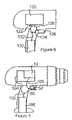
- FIG. 1is a side view of an example hand tool incorporating the locking device
- FIG. 2is a cutaway view of the interior of the locking arm and solenoid of the instant invention
- FIG. 3is a top view of an example controller configuration
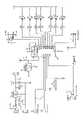
- FIG. 4is the schematic of an example wiring for the locking device for use with a hand tool
- FIG. 5is a cutaway side view of the interior of the hand tool of FIG. 1 ;
- FIG. 6is a cutaway side view of an alternate embodiment of a hand tool utilizing the disclosed locking device
- FIG. 7is a side view of the instant device for use with a air tool system
- FIG. 8is a schematic of the wiring for use with the locking device used in conjunction with air tools
- FIG. 9is a schematic of the wiring for use with electronic devices.
- FIG. 10is a schematic of the wiring for use with the locking device incorporating the analogue function
- FIG. 11is a flow chart for programming a multi-operation device
- FIG. 12is a flow chart for programming a single operation device
- FIG. 13is a flow chart for programming an electronic device including a reset option
- FIG. 14is a flow chart for programming an electronic device designating specific events, times and users.
- the disclosed inventionrelates to a programmable device having multiple programmable features including, but not limited to, restricting accessibility to specific portions of the device and a coded locking mechanism that discourages theft and restricts or eliminates use during a predetermined time frame.
- a coded locking mechanismthat discourages theft and restricts or eliminates use during a predetermined time frame.
- further safety advantagesare achieved simply by its existence. It will be obvious to anyone who buys an item containing the locking device that unless the seller has the code, the item is most likely stolen.
- the disclosed locking devicecontrols the activation of the item, preventing activation without the entry of user codes. Without access to the codes, the item is useless and unsaleable.
- Electronic devicessuch as cell phones, palm pilots and other hand held data access devices, cameras, computers, VCRs, televisions, MP3 players, etc. all fall into the category of easy theft devices with high resale value.
- Their use of programmable chipsmakes these valuable devices easy to modified to incorporate the advantages of the disclosed system.
- the devicein devices such as VCRs and televisions, can be a separately encased unit that is retrofitted into the power source, such as the power cord or plug.
- the power sourcesuch as the power cord or plug.
- microchips, microprocessors or analog, technologypermits various functions to be monitored, such as scheduling service, based on use time or the number of hours an item has been used.
- the locking mechanismis preferably of a type that does not require the use of a key, or other device, thereby avoiding an additional item to lose or carry.
- Access through keypads or other locking meanscan be used, such as magnetic card readers, fingerprint or retinal recognition, standard keys, telephone signals, or any applicable wireless technology, etc.
- the method of programming the deviceis dependent upon the type of device, size, etc. For example, touch key scanning, or other method of transmission having static data, can easily be incorporated into the device, thereby permitting data relating to the item to be tracked.
- the disclosed technologyprovides benefits in a laboratory or other setting where equipment is centralized and removed for use.
- Each employeewould have a personalized touch key, or other wireless or non-wireless access means, that would record the employee name, time of activation, and any other information required by the employer.
- the personalized access devicecan also carry the ID code enabling use of the device, thus preventing use by unauthorized personnel.
- the disclosed deviceWhen installed on a computer, the disclosed device can be connected directly to the power supply or programmed into the chip, hard drive or other storage/memory device; permitting businesses that sell computer time to automatically shut down the computer unless additional time is purchased.
- the devicepermits parental control on the amount of time, or specific time periods, the computer, or other electronic device such as a TV, can be used by a child.
- the computer, VCR or TVcould only be activated after homework time is over, etc.
- Computersare especially adaptable to keyboard programming of the device, although a keyboard interface can be included with any of the locking devices disclosed.
- a program embedded in the device's microchip and/or harddrivecan allow for a simple timer setting that is activated through key input on the keyboard.
- a direct coding keycan be incorporated on the keyboard that automatically accesses the program and permits activation, setting changes, etc.
- computer lock out programsare known in the prior art, they totally lock out use of the computer in an all or nothing method.
- the disclosed devicepermits access to the computer for a predetermined period of time either at random or within a specific schedule time, optionally, to extend the amount of time to use the device without interruption.
- the systemcan be set to enable the computer to be turned at a predetermined time, used for a specific time period, after which the computer cannot be used until the preprogrammed activation time.
- One of the programmable modes disclosed hereinis a partial activation mode, as described in detail hereinafter with relationship to cell phones.
- the usercan restrict partial use of the electronic equipment, for example a computer can be programmed to restrict certain programs, such as web access, instant messages, email, specific websites or type of site, during specific blackout time periods. For example, children could be prevented from surfing the web except during specific time periods. Or computer games could only be accessed for a restricted time, however the computer could be used for word processing or other homework related activities.
- This modeenables the computer to be used, but in a restricted manner, based upon primary user programming. Additionally, sub-user ID's can be used to permit individual access to an electronic device. This is advantageous with children having different age restrictions by permitting the older children to access programs, make long distance calls, etc., that are unavailable to younger children.
- the disclosed locking deviceis also advantageous for rental equipment, such as generators, compressors, VCR's, etc., in that the rented equipment can be programmed for a specific period of time and after that point be automatically deactivated. This discourages the theft of rental equipment, thereby reducing insurance and liability, since by preventing unauthorized use, especially when used in conjunction with larger equipment, insurance rates would potentially be reduced.
- the timing activation devicecan be activated through the remote controller. Once activated the program would appear on the screen and utilize either existing or specific keys to set the shut down time, user time periods, or extend the time period, etc. This would be an inexpensive addition to a controller and increase user convenience. Alternatively, the controller itself can be used to set the time of use, without the appearance of the setting program on the screen.
- a hand drillas illustrated in FIGS. 1 and 2 , is used to illustrate the disclosed mechanism used to limit user time, however this is as an example only and is not intended to limit the invention.
- the power tool 10is illustrated in FIG. 1 ready for use, incorporating a numeric keypad 12 as the locking mechanism and other activating mechanisms will be apparent to those skilled in the art.
- the timecan be set through any means appropriate to the equipment being used as well as the final use. For example, the time can be through repeatedly touching a specific key, jumping the time by predetermined increments. Alternatively, an “enter” key can be provided which allows entry of the unlocking code and subsequent entry of a predetermined period of time.
- all timed locking devicesare provided with nonvolatile memory to prevent the loss of programmed instructions in the event the item's battery goes dead or is removed. This is more critical with rechargeable hand tools where completely discharging the battery is sometimes required to fully recharge.
- an LED display 14 of FIG. 1can be included which indicates the activation time remaining and, if desired, the current status of the tool.
- the statuscan include, for example, current battery power (both during recharge and discharge), pressure remaining when air tools are used, rpm and direction of drills, etc. This is of optimum use in monitoring the status of rechargeable batteries. Since many rechargeable batteries do not either fully charge unless fully discharged prior to recharging, the battery-monitoring device permits optimum use and management of the battery. It should also be noted that an LED could be provided on the recharging device to monitor the battery recharge thereby serving as a double check to the LED on the device being charged.
- FIG. 2one design of the internal activation unit 40 is illustrated.
- the locking arm 48is supported between the upper case side 42 and the lower case side 44 .
- the spring tension 50is designed to place the solenoid contact 56 in physical contact with the solenoid 52 when the locking arm 48 is pulled back during use. Once the locking arm 48 is released, the solenoid contact 56 is removed from contact with the solenoid 52 .
- the solenoid 52receives power from the battery 108 ( FIG. 5 ) through the controller 80 , an example of which is illustrated in more detail in FIG. 3 .
- the controller 80serves as the central processing area, with all input and output passing through the controller 80 .
- the controller 80is connected directly to the locking mechanism, such as a numeric keypad 12 , through the keypad wiring 100 .
- the battery wiring 102 and motor wiring 104also feed into the controller 80 .
- the locking meanssuch as numeric keypad 12
- all connectionsare made and power is free to go to the driver specific to the power tool 10 .
- the exact schematic of the wiringis not critical, as the criticality lies with in the interaction between the locking means and the controller 80 .
- the interior of the hand tool 10as shown in FIG. 5 , is traditionally spaced, with the controller 80 located within the handle area.
- the various connecting wires 100 , 102 and 104are exposed and, in the event of theft, the case can be opened and the wires cut and crossed to bypass the controller 80 .
- the caseis provided with a safety lock key having a number of different embodiments.
- One embodimentis to incorporate a locking member, wired to the control through the locking wire 156 , that is deactivated by a locking code, key or other compatible methods.
- the controller 80can be programmed to allow the case to release, for example through a separate code being entered or by holding down the last number of the existing code for a predetermined time period.
- a separate codeis preferable in that it prevents any unauthorized access to the interior of the case.
- the solenoid 126 and wiring 122are encased in an epoxy, indicated herein as region 128 , as illustrated in FIG. 6 .
- region 128By encasing the wiring 122 within the epoxy, it is impossible to rewire the unit and bypass the controller 124 .
- Other materialsknown in the art, can be used to replace the epoxy.
- the wiring 122 from the motor 120exits the motor casing proximate the controller 124 , which has been placed as close as possible to the solenoid 126 . This revised placement reduces the area to be protected, thereby reducing material and labor costs. Revising the placement of the battery 130 is difficult, preventing in some instances the battery wiring 132 from being covered.
- the controller 124 and solenoid 126both encased in epoxy, there would be no value to cutting the battery wire 132 , as there would not be any accessible power connections.
- the locking deviceis illustrated being used with an air tool 200 , although it should be noted that the device can also be used with propane, gas, and diesel tools and equipment.
- the controller unit 202is located in the handle 204 of the air tool.
- the touch key-wiring 100goes to the controller 80 , as does the battery wire 102 and the motor wire 104 .
- the touch key wiring 150 and solenoid 154 wiringfeed into the controller 152 and onto the driver, the battery and motor connections being eliminated.
- the disclosed devicecan be easily incorporated with electronic equipment.
- the programming of the equipmentcan be through a number of methods and additional methods will become evident as technology changes and will be evident to those skilled in the art.
- Rewrite swipe cardsare gaining popularity and can easily be incorporated with the disclosed device.
- the cardscan be rewritten with the new codes using a computer or other applicable device, such as a palm or remote control.
- a computer programcan contain the applicable coding for all the electronic devices which incorporate the disclosed technology.
- a usercan select the functions to be incorporated for each device and write them to the card. The user can then use the same swipe the card to program each of the electronic devices available as each device will recognize its codes and ignore programming for other devices.
- a small hard drivesuch as used in digital cameras, can be used to program the various electronic devices.
- the schematic of FIG. 15is an example of the electronics for a device being incorporated into a computer, VCR, television, etc. As can be seen, the basic functioning of the antitheft device is the same as used for a battery operated, air or electric tools or other devices. As in the schematics disclosed heretofore, the touch key wiring 302 feeds into the controller 304 . In this embodiment, however, the electric wiring 306 is connected to the controller 304 through the latching relay wires 308 .
- the schematic of FIG. 16provides an example of the electronic layout, disclosed in FIG. 15 , to incorporate the analogue function into the device through analog wiring 350 .
- cellular phonesare a small sized, high dollar theft item that is difficult to protect.
- the thiefwould know that there was no way to stop the phone from shutting down at a pre-designated time and that once the predesignated time had expired the phone would be unusable.
- the usercould program the phone to shut off permanently at the expiration of a predetermined time or, alternatively at a preset time.
- the disclosed systemfurther enables a user to set the phone to shut down for a predetermined period of time, with automatic reactivation at the end of the time period.
- the ability to turn the phone off for a predetermined period of time, after which it automatically reactivates for a predetermined time based upon user programming,is beneficial for people attending meetings, movies, or some other activity that requires the phone to be turned off. Since the phone will automatically reactivate, the user does not need to worry about turning the phone back on.
- the phonecan also be set to either receive calls or make calls, during a user programmed time period, as well as the standard incoming/outgoing mode.
- the phonecan be set to forward all of the phone owner's incoming calls to their voice mail or other call forwarded location, while still allowing the person having the phone to make outbound calls.
- the person having the phonecan receive calls, but cannot use the phone to call out.
- the code enabling the programming disclosed hereinis preferably on the phone's, or other equipment's, permanent memory device, such as hard drive, microchip, etc. and is not solely dependent upon any temporary software, phone card or other removable system.
- a delayed activationcan also be programmed into any of the devices to enable activation at a specific time or after a certain amount of time has lapsed.
- the foremancan program the tool to activate in thirty minutes and to stay activated for an additional eight hours.
- the commandscan be set through a variety of methods.
- On equipment that has a built in a screensuch as a digital camera or cell phone, the screen can be used to monitor the exiting settings and program new settings.
- an external LED displayIn devices without screens an external LED display, voice activation, or some other means of forming communicating between the device and the user can be incorporated.
- the existing command or program buttonscan be used to program the device or additional buttons can be incorporated into the design at the time of manufacture.
- remotes, infrared, Bluetooth, or other wired or wireless devicescan be used as a programming tool.
- FIG. 11A sample of a sequence for the user to follow when programming a cell phone is illustrated in FIG. 11 .
- the systeminquires whether the user would like to activate the locking system 602 or, no changes are to be made entering the use mode 603 .
- the manufacturersets a default maximum amount of time that the phone can be continuously activated, after which it automatically shuts down. This maximum operational period is preferably applicable not only to cell phones but all devices using the disclosed locking system. The maximum time can be set by the user using a separate code, either single or multiple use, from the standard programming.
- the additional option of resetting the systemis added, enabling the user to either deactivate or reset the system 803 .
- the userenters their personal code 812 and selects whether they wish to deactivate 812 or reset 814 . If deactivate 812 is selected the system enters normal operation 810 , again incorporating the preferred restriction of a maximum operating time. If the user selects to reset 814 the system then goes to the timed operation sequence 816 , the system continues following arrows A 1000 and A 1002 , following the sequence as set forth in FIGS. 11 and 12 . It should be noted that arrow A 1004 serves as the return from the “no” selection at the end of the programmable options.
- fall backas used herein can relate to either the default set by the manufacturer or the last programmed codes.
- the fall back preferenceis set at the initial programming by the user at the time of set up.
- the Timed Operation mode, or scheduling 614provides the user the ability to shut down the operation of the device by clock setting 636 or number of minutes 640 .
- clock setting 636the user then enters the time of day that the device shuts down 638 .
- minutes 640 modulethe number of minutes prior to shutting down is requested 642 .
- a preset maximum time of operationwill still prevail after which the user code would be required to reactivate the phone.
- the selection of “no” as a responsebrings up the sleep mode 620 operation which, if entered through, enables the user to set a start time 644 and an end time 646 during which the device is inoperable.
- the end time 650is similar to the sleep mode end time 646 .
- the partial operation mode 634enables the user to separate the ability to make calls 652 from the ability to receive calls 654 .
- the make calls 652 operationis selected, the user enters the start time 656 and the end time 658 during which calls can be made.
- the receive calls 654also permits start time 660 and end time 662 entry. In the event the user selects none of the modules the system returns to the activate locking system mode 604 .
- the devicecan be programmed to accept multiple different commands, such as a sleep mode 620 where it does not operate from the start time 644 to the end time 646 and timed operation 614 in which the device shuts down 638 at 8:00 pm.
- commandssuch as a sleep mode 620 where it does not operate from the start time 644 to the end time 646 and timed operation 614 in which the device shuts down 638 at 8:00 pm.
- the devicescan be provided with an extend time mode 822 , as illustrated in FIG. 20 , and it should be noted that although the devices can be provided with this mode, as noted heretofore, it cannot permit endless extended time as that would eliminate the security concept.
- the useractivates the device 802 , selects to activate/reset the system 803 and enters the personal code 812 , the option of extend time 822 is presented.
- the extend time option 822the user can extend the time of the current programming equal to, or less than, the original program period.
- the amount of time for extensioncan be determined by the manufacturer and would be unchangeable by the user. For example, the phone can either shut down upon expiration of a preprogrammed maximum operational period or after a preset number of extensions 822 .
- a default timehas been entered. Therefore, once the user activates the device 700 , responds positively to activating the locking system 702 and enters the personal code 704 .
- the default start time 708is displayed, giving the user the opportunity to increase 710 or decrease 718 the time by either minutes 712 or hours 714 .
- minute and hoursfor example only and the time categories can be days, weeks, or any increment selected by the manufacturer.
- the default end time 716is adjusted in the same fashion.
- Each of the modes in this Figureprovide the default time options, however it should be noted that the default modes illustrated in FIG. 19 can be also included in conjunction with the timer setting modes illustrated in FIG. 18 . Alternatively the user can be provided with the choice of whether to select the default or the timer settings.
- FIG. 13would be more applicable for cameras, TVs, computers and other devices that have only one type of operation. In other words do not have the dual operations, send and receive, as does a cell phone or a VCRs record and play. It should be noted that the system as disclosed in FIG. 13 is used in the same way as explained in FIG. 12 .
- an eventincludes computer programs, television shows, radio stations, or any other specific event that is viewed or listened to through the electronic device. For example, between 7:00 pm and bedtime, by controlling the stations that can be viewed, a 12 year old could only watch specific shows and, at bed time, the TV would no longer be accessible.
- the primary, or programming useractivates the device 900 , and is asked whether they are to program 934 or view 932 . Entry of program 934 inquires whether the primary user would like to activate the locking system 902 or deactivate the system 903 .
- the personal code 904is requested and the device enters fall back operation 910 , again with the maximum running period or previously programmed time. If the primary user wishes enter a programmed operation 614 , they enter the start time 940 , end time 942 , user code 946 and the program code 952 while other programs are blocked. This tells the system that at the start time 940 the secondary, or non-programming user matching secondary user code 946 can watch the program entered into the program code 952 while other programs are blocked. To facilitate programming, multiple user codes 946 can be entered, or checked off on a list. Once the program code 952 is entered, the user can either repeat 948 the programming event 914 or end 950 the event. When returned to the programmed event 914 , the user can either program another event or continue on to other modes contained on the device, such as those illustrated in FIG. 13 . Alternatively, a next mode 954 can be accessed directly from the program code 952 module.
- the user code 930is entered and the system permits viewing of the preprogrammed events. This system is for use predominately on TV's and computers, however other applications will be evident to those skilled in the art.
- One use of the disclosed inventionis in commercial industries with workers using company owned tools and equipment, computers, motel TVs and VCRs, etc.
- the tools, or other equipmentare activated in the morning to run for an entire shift, at which point they shut down. This prevents theft from outside sources as well as employees. Additionally by reactivating the tools each morning, a “safety check” can be incorporated with the activation to prevent faulty equipment from being used.
- the locking devicecan further be used with bicycles, shopping carts, wheelchairs, etc. It should be noted, however, that since the locking devices disclosed herein operate on bicycles by stopping movement of the pedals, this device is not recommended for bikes, or other items that have foot brakes. In the event, that the device was activated during use, the user would be unable to activate the brakes.
- the example used hereinis a bicycle, however the device, as disclosed, can easily be adapted for a variety of other wheeled devices.
- the locking device for use with bicycles, or other applicable devicespreferably has a weight of about one (1) pound or less.
- FIGS. 9 , 10 and 11illustrate a manual version of the locking device 200 for use with wheeled vehicles and is illustrated on a bicycle.
- the locking mechanisms within the locking deviceare located within a protective case 202 to prevent tampering.
- the case 202is welded to the front frame 230 and rear frame 232 as currently done in the art replacing the standard joint at the juncture of the front and rear supports.
- the case 202is slightly larger than standard cases to accommodate the locking device 200 .
- the pedal axle 204passes through the case 202 and is attached to the pedals 236 as known in the art.
- the engagement disk 208has a centered receiving hole 220 that permits the disk 208 to be mounted on the axle 204 .
- the disk 208is welded to the axle 204 to cause the disk 208 to rotate with the axle 204 as the bicycle is pedaled.
- the disk 208contains a series of receiving holes 222 around its periphery.
- the receiving holes 222are dimensioned to receive the locking bar 210 that has been encased in the locking brace 216 .
- the locking brace 216is secured to the case 202 to prevent movement of the bar 210 and therefore movement of the pedals 236 once the bar 210 is in the locked position.
- the locking bar 210is drawn into the locking brace 216 .
- the bar 210engages the receiving holes 222 of the disk 208 and prevents the pedals 236 from turning.
- the locking brace 216must be securely affixed to the case 202 to prevent the brace 216 from dislodging when a user attempts to pedal during the locked mode. Additionally, the locking bar 210 must have sufficient strength to prevent the bar 210 from snapping or bending. In the embodiment of FIG. 9 the bar 210 is placed into either the locked or unlocked position by a key lock 206 , or other mechanically operated device. The interior mechanisms moving the locking bar 210 in response to the key lock 206 are like those of dead bolts for doors and other methods will be known to those skilled in the art.
- a bottom plate 214is incorporated into the locking device 200 .
- the bottom plate 214 illustratedhas a rotating lock 212 that is secured to a locking plate 220 .
- the flanges 218extend into the open area of the case 202 and provide support for the locking plate 220 when rotated to the locked position. Rotation of the rotating lock 212 moves the locking plate 220 into a position to clear the flanges, thereby permitting removal of the bottom plate 214 .
- the locking mechanism for the bottom plateis an example of a method for locking the bottom plate onto the case and other methods known in the art can be used.
- FIGS. 12-14An automatic embodiment of the locking mechanism for use with bicycles is illustrated in FIGS. 12-14 .
- the engagement disk 308is welded to the pedal axle 324 as described heretofore.
- the interacting locking bar 326is operated by a battery-powered solenoid 304 .
- the solenoid 304is maintained in position through use of a casing 306 that is securely affixed to the outer case 302 .
- the locking bar 326must be capable of withstanding the pressure exerted by a person attempting to pedal the bike.
- the batteries 340 to power the solenoid 304can be contained within the front support 342 or other location convenient for manufacture.
- the use of a battery-powered solenoidalso permits the use of a timer as disclosed for use with the hand tool of FIG. 1 .
- the analogue timeris advantageous for companies renting bikes by the hour or day as the timer can be activated upon the bike being removed from the shop and the time read and calculated upon return.
- the timer readout, entry method, etc.can be incorporated in either the front support 342 or back support 344 .
- the base plate 312uses an alternate design to the embodiment of FIG. 9 .
- the base plate 312is provided with a key lock 314 that is attached to dual rotating bars 320 and 322 .
- the sides of the case 302are provided with flange pairs 318 and 316 that are dimensioned to interact with the rotating bars 320 and 322 .
- the key lock 314is turned, the bars 320 and 322 move out of their interaction with the flange pairs 318 and 316 , thereby releasing the base plate 312 .
Landscapes
- Engineering & Computer Science (AREA)
- Mechanical Engineering (AREA)
- Lock And Its Accessories (AREA)
Abstract
Description
Claims (28)
Priority Applications (4)
| Application Number | Priority Date | Filing Date | Title |
|---|---|---|---|
| US10/339,711US7394347B2 (en) | 1997-10-27 | 2003-01-09 | Locking device for electronic equipment |
| TW92103630ATWI240155B (en) | 2002-10-18 | 2003-02-21 | Locking device for electronic equipment |
| US12/166,180US8289132B2 (en) | 1997-10-27 | 2008-07-01 | Locking system for electronic equipment |
| US13/653,212US8963681B2 (en) | 1997-10-27 | 2012-10-16 | Operating control system for electronic equipment |
Applications Claiming Priority (4)
| Application Number | Priority Date | Filing Date | Title |
|---|---|---|---|
| US6594197P | 1997-10-27 | 1997-10-27 | |
| US09/178,837US6469615B1 (en) | 1997-10-27 | 1998-10-26 | Locking device for tools and equipment |
| US10/273,819US20030043016A1 (en) | 1998-10-26 | 2002-10-18 | Locking device for electronic equipment |
| US10/339,711US7394347B2 (en) | 1997-10-27 | 2003-01-09 | Locking device for electronic equipment |
Related Parent Applications (2)
| Application Number | Title | Priority Date | Filing Date |
|---|---|---|---|
| US10/273,819Continuation-In-PartUS20030043016A1 (en) | 1997-10-27 | 2002-10-18 | Locking device for electronic equipment |
| US69079503AContinuation-In-Part | 1997-10-27 | 2003-10-22 |
Related Child Applications (1)
| Application Number | Title | Priority Date | Filing Date |
|---|---|---|---|
| US12/166,180Continuation-In-PartUS8289132B2 (en) | 1997-10-27 | 2008-07-01 | Locking system for electronic equipment |
Publications (2)
| Publication Number | Publication Date |
|---|---|
| US20030107470A1 US20030107470A1 (en) | 2003-06-12 |
| US7394347B2true US7394347B2 (en) | 2008-07-01 |
Family
ID=27370887
Family Applications (1)
| Application Number | Title | Priority Date | Filing Date |
|---|---|---|---|
| US10/339,711Expired - Fee RelatedUS7394347B2 (en) | 1997-10-27 | 2003-01-09 | Locking device for electronic equipment |
Country Status (1)
| Country | Link |
|---|---|
| US (1) | US7394347B2 (en) |
Cited By (25)
| Publication number | Priority date | Publication date | Assignee | Title |
|---|---|---|---|---|
| US20070221832A1 (en)* | 2006-03-21 | 2007-09-27 | Toon-Jeow Foo | Portable electronic device with electronic lock |
| US20070252675A1 (en)* | 2004-09-24 | 2007-11-01 | David Lamar | Electronically enabling device remotely |
| US20070271972A1 (en)* | 2005-01-12 | 2007-11-29 | Komatsu Ltd. | Lock Controller of Working Machine, and Working Machine |
| US20080150677A1 (en)* | 2005-01-11 | 2008-06-26 | Komatsu Ltd. | Lock Control System and Method for Working Machine, Working Machine, Lock Control Device and Lock Control Management Device for Working Machine |
| US20080281664A1 (en)* | 2007-05-07 | 2008-11-13 | David Matthew Campbell | System and method for managing use and availability of equipment |
| US20090015372A1 (en)* | 1997-10-27 | 2009-01-15 | Darren Kady | Locking System for Electronic Equipment |
| US20090212904A1 (en)* | 2008-02-25 | 2009-08-27 | Sanyo Electric Co., Ltd. | Electronic device provided with theft prevention function, and method for preventing theft of electronic devices |
| US20090313651A1 (en)* | 2008-06-17 | 2009-12-17 | Sanyo Electric Co., Ltd. | Electronic Apparatus Having Operation Restriction Function |
| US20100264752A1 (en)* | 2009-04-17 | 2010-10-21 | Shining Union Limited | Power supply control socket |
| US20110032076A1 (en)* | 2009-08-04 | 2011-02-10 | Raytheon Company | Method and System for Generating a Biometric Query Plan |
| US8660531B2 (en) | 2010-11-03 | 2014-02-25 | Blackberry Limited | Access to locked functions |
| US20140158389A1 (en)* | 2011-07-24 | 2014-06-12 | Makita Corporation | Theft-deterrence system for power tool system, and adapter and method therefor |
| US8963681B2 (en) | 1997-10-27 | 2015-02-24 | Direct Source International, Llc | Operating control system for electronic equipment |
| US9310963B2 (en) | 2007-06-29 | 2016-04-12 | Nokia Technologies Oy | Unlocking a touch screen device |
| US9467862B2 (en) | 2011-10-26 | 2016-10-11 | Milwaukee Electric Tool Corporation | Wireless tracking of power tools and related devices |
| US9466198B2 (en) | 2013-02-22 | 2016-10-11 | Milwaukee Electric Tool Corporation | Wireless tracking of power tools and related devices |
| US9537335B2 (en) | 2011-07-24 | 2017-01-03 | Makita Corporation | Adapter for power tools, power tool system and method for wirelessly communicating maintenance information therefor |
| US9547692B2 (en) | 2006-05-26 | 2017-01-17 | Andrew S. Poulsen | Meta-configuration of profiles |
| US9577450B2 (en) | 2011-07-24 | 2017-02-21 | Makita Corporation | Charger for hand-held power tool, power tool system and method of charging a power tool battery |
| US9733827B2 (en) | 2010-09-01 | 2017-08-15 | Nokia Technologies Oy | Mode switching |
| US9756402B2 (en) | 2015-05-04 | 2017-09-05 | Milwaukee Electric Tool Corporation | Power tool and method for wireless communication |
| US9830049B2 (en) | 2011-12-12 | 2017-11-28 | Nokia Technologies Oy | Apparatus and method for providing a visual transition between screens |
| US10158213B2 (en) | 2013-02-22 | 2018-12-18 | Milwaukee Electric Tool Corporation | Worksite power distribution box |
| US10437228B2 (en) | 2014-04-02 | 2019-10-08 | Ridge Tool Company | Electronic tool unlocking system |
| US11022955B2 (en) | 2014-04-02 | 2021-06-01 | Ridge Tool Company | Smart tool systems |
Families Citing this family (22)
| Publication number | Priority date | Publication date | Assignee | Title |
|---|---|---|---|---|
| US20050170811A1 (en)* | 2004-02-04 | 2005-08-04 | Pelaez Mariana B. | Protected mode for mobile communications terminals |
| JP4438946B2 (en)* | 2004-09-08 | 2010-03-24 | 日本電気株式会社 | Additional function control system and communication terminal |
| JP4678199B2 (en)* | 2005-02-10 | 2011-04-27 | パナソニック電工株式会社 | Electric tool |
| JP2006224208A (en)* | 2005-02-15 | 2006-08-31 | Max Co Ltd | Tool and process control data collection system |
| JP4612482B2 (en)* | 2005-06-17 | 2011-01-12 | 大日本印刷株式会社 | Usage management system |
| TWI590929B (en)* | 2008-05-20 | 2017-07-11 | Max Co Ltd | Tool |
| US20110090045A1 (en)* | 2009-10-19 | 2011-04-21 | Smith Douglas W | Lockable container with time-controlled remote control |
| JP2012061540A (en) | 2010-09-15 | 2012-03-29 | Alpha Corp | Electric hand tool |
| DE102010053584A1 (en) | 2010-12-06 | 2012-06-06 | Andreas Stihl Ag & Co. Kg | Usage lock for a hand-held implement |
| US9256996B2 (en)* | 2011-10-11 | 2016-02-09 | Schneider Electric Buildings, Llc | Method and system for training users related to a physical access control system |
| US20140156874A1 (en)* | 2012-11-30 | 2014-06-05 | Thomson Licensing | Method and system for a multimedia device operable by a control device |
| US20140166324A1 (en)* | 2012-12-13 | 2014-06-19 | Black & Decker Inc. | Power Tool User Interface |
| DE102012112835A1 (en)* | 2012-12-21 | 2014-06-26 | Robert Bosch Gmbh | System with a central license management unit and a tool device |
| JP6085225B2 (en)* | 2013-06-27 | 2017-02-22 | 株式会社マキタ | Screw tightening electric tool |
| WO2015017797A1 (en)* | 2013-08-02 | 2015-02-05 | Kid Case L.L.C. | Method and system for using a supervisory device with a mobile device |
| CN103412500A (en)* | 2013-08-26 | 2013-11-27 | 广西柳工机械股份有限公司 | Engineering mechanical equipment locking method |
| DE102014215045A1 (en)* | 2014-07-31 | 2016-02-04 | Robert Bosch Gmbh | High-performance portable power tool |
| US20160378097A1 (en)* | 2015-06-25 | 2016-12-29 | Ingersoll-Rand Company | Security lock-out for power tools |
| DE102015212028A1 (en)* | 2015-06-29 | 2016-12-29 | Robert Bosch Gmbh | Operating device for a hand tool |
| DE102017205430A1 (en)* | 2017-03-30 | 2018-10-04 | Robert Bosch Gmbh | machine tool |
| US11763610B2 (en)* | 2018-09-13 | 2023-09-19 | Milwaukee Electric Tool Corporation | Anti-theft systems and devices for battery-powered power tools |
| DE102021209654A1 (en)* | 2021-09-02 | 2023-03-02 | Robert Bosch Gesellschaft mit beschränkter Haftung | Driving tool with a human machine interface |
Citations (100)
| Publication number | Priority date | Publication date | Assignee | Title |
|---|---|---|---|---|
| US4081754A (en) | 1977-01-31 | 1978-03-28 | Jackson Joseph N | Programmable television receiver controllers |
| US4263781A (en) | 1979-07-25 | 1981-04-28 | United Technologies Corporation | Integral rocket-ramjet open loop fuel control system |
| US4279012A (en) | 1978-10-23 | 1981-07-14 | Massachusetts Microcomputers, Inc. | Programmable appliance controller |
| US4370721A (en) | 1980-09-02 | 1983-01-25 | Cincinnati Milacron Inc. | Method for modifying programmed positions by using a programmably controlled surface sensing element |
| US4484220A (en) | 1981-09-29 | 1984-11-20 | Idea Research Development Corp. | Television monitor |
| US4574752A (en) | 1984-10-15 | 1986-03-11 | Marvion E. Reichert, Jr. | Internal combustion engine shutdown device |
| JPS61283228A (en) | 1985-06-10 | 1986-12-13 | Nec Corp | Television receiver |
| US4700296A (en) | 1985-04-19 | 1987-10-13 | Palmer Jr Roy A | Electronic access control system |
| US4769765A (en) | 1986-11-10 | 1988-09-06 | Green David L | Controlled access programmable event timer system |
| US4959860A (en)* | 1989-02-07 | 1990-09-25 | Compaq Computer Corporation | Power-on password functions for computer system |
| US4967305A (en) | 1989-01-06 | 1990-10-30 | Datatrak, Inc. | Electronic door lock apparatus, system and method |
| US5036314A (en) | 1988-01-12 | 1991-07-30 | Sarin S.S. Ausiliari E Ricerca Informatica | Method and system for the integrated supply of telematic services and graphic information to user terminals, particularly for advertising purposes |
| US5051837A (en) | 1990-06-06 | 1991-09-24 | Mcjunkin Thomas N | Home entertainment equipment control apparatus |
| US5150298A (en) | 1989-03-13 | 1992-09-22 | Sumitomo Electric Industries, Ltd. | Brake control device in an antilock brake system |
| US5191231A (en) | 1991-04-30 | 1993-03-02 | Woodrow Berry | Timer for electrical appliances |
| US5231661A (en)* | 1991-07-31 | 1993-07-27 | Gold Medal Kids, Inc. | Television viewing control device and method |
| US5231310A (en)* | 1990-09-05 | 1993-07-27 | Oh Soo Young | Electrical and electronic appliance lock |
| US5253066A (en) | 1989-06-01 | 1993-10-12 | Vogel Peter S | TV recording and viewing control system |
| US5278538A (en) | 1992-04-20 | 1994-01-11 | Ainsworth Kathryn L | Bicycle security system |
| US5291067A (en) | 1990-01-31 | 1994-03-01 | Suzuki Kabushiki Kaisha | Electric circuit system for motorcycle |
| US5331353A (en) | 1992-03-10 | 1994-07-19 | Mindmaster Inc. | Device for limiting the amount of time an electrical appliance such as a television may be used |
| US5377317A (en) | 1991-12-20 | 1994-12-27 | International Business Machines Corporation | Method and apparatus for distinctively displaying windows on a computer display screen |
| EP0630802A2 (en) | 1993-06-22 | 1994-12-28 | Hans-Jürgen Vetterick | Bicycle safety device |
| US5382983A (en) | 1993-07-29 | 1995-01-17 | Kwoh; Daniel S. | Apparatus and method for total parental control of television use |
| US5510780A (en) | 1994-02-18 | 1996-04-23 | Profit Plus Corporation | Time cycled security code and activation control system |
| US5524195A (en) | 1993-05-24 | 1996-06-04 | Sun Microsystems, Inc. | Graphical user interface for interactive television with an animated agent |
| US5523796A (en) | 1994-05-20 | 1996-06-04 | Prevue Networks, Inc. | Video clip program guide |
| US5526034A (en) | 1990-09-28 | 1996-06-11 | Ictv, Inc. | Interactive home information system with signal assignment |
| US5530230A (en) | 1994-10-20 | 1996-06-25 | Smith; Andrew M. | Variable password safety interlock system for microwave ovens and other appliances |
| US5531467A (en) | 1994-02-10 | 1996-07-02 | Schueman Enterprises, Inc. | Safety means for controlling an air powered actuator for retracting the locking pins of a slider |
| US5534911A (en) | 1994-11-02 | 1996-07-09 | Levitan; Gutman | Virtual personal channel in a television system |
| US5563586A (en) | 1994-07-29 | 1996-10-08 | Ambitech Industries, Inc. | Apparatus for limiting control of electrical equipment |
| US5589892A (en) | 1993-09-09 | 1996-12-31 | Knee; Robert A. | Electronic television program guide schedule system and method with data feed access |
| US5600364A (en) | 1992-12-09 | 1997-02-04 | Discovery Communications, Inc. | Network controller for cable television delivery systems |
| US5642805A (en) | 1995-10-12 | 1997-07-01 | Tefft; Brian | Input device lock |
| US5653135A (en) | 1992-01-13 | 1997-08-05 | C & M Technology, Inc. | High security lock mechanism |
| US5684861A (en) | 1995-12-04 | 1997-11-04 | Lewis; Walter F. | Apparatus and method for monitoring cellular telephone usage |
| US5805763A (en) | 1995-05-05 | 1998-09-08 | Microsoft Corporation | System and method for automatically recording programs in an interactive viewing system |
| US5819156A (en) | 1997-01-14 | 1998-10-06 | Compaq Computer Corp. | PC/TV usage tracking and reporting device |
| US5850218A (en) | 1997-02-19 | 1998-12-15 | Time Warner Entertainment Company L.P. | Inter-active program guide with default selection control |
| US5898778A (en)* | 1995-07-05 | 1999-04-27 | Antonini; Pierre | Method and device for temporarily authorizing the use of a programme protected by an electronic cartridge |
| US5917256A (en) | 1997-02-04 | 1999-06-29 | Broadbent, Ii; Frederick J. | Timing device for blocking television signals |
| US5930446A (en) | 1995-04-08 | 1999-07-27 | Sony Corporation | Edition system |
| US5940755A (en) | 1996-12-31 | 1999-08-17 | Mci Communications Corporation | System and method for wireless network of unlicensed personal communications service areas with local switch interfaces and enhanced customer features |
| US5969748A (en) | 1996-05-29 | 1999-10-19 | Starsight Telecast, Inc. | Television schedule system with access control |
| US5974364A (en) | 1997-01-29 | 1999-10-26 | Samsung Electronics Co., Ltd. | Method for controlling a test mode of an electric device |
| US5982355A (en) | 1993-11-05 | 1999-11-09 | Jaeger; Denny | Multiple purpose controls for electrical systems |
| US6005489A (en) | 1994-08-18 | 1999-12-21 | Atlas Copco Tools Ab | Electric power tool with code receiver |
| US6098878A (en) | 1998-04-30 | 2000-08-08 | Ericsson Inc. | Tariff management apparatus and method for communications terminals using smart cards |
| US6111240A (en)* | 1997-08-14 | 2000-08-29 | Sharp Kabushiki Kaisha | Electric appliance |
| WO2001006786A1 (en) | 1999-07-15 | 2001-01-25 | Fotonation, Inc. | Digital camera with biometric security |
| WO2001017209A1 (en) | 1999-08-31 | 2001-03-08 | Nokia Mobile Phones Limited | A method and apparatus for controling functionality of a device based on time of day |
| US6202014B1 (en)* | 1999-04-23 | 2001-03-13 | Clark Equipment Company | Features of main control computer for a power machine |
| US6223265B1 (en) | 1993-09-17 | 2001-04-24 | Hitachi, Ltd. | Single-chip microcomputer synchronously controlling external synchronous memory responsive to memory clock signal and clock enable signal |
| US6226793B1 (en) | 1995-02-14 | 2001-05-01 | Daniel S. Kwoh | Apparatus and method for allowing rating level control of the viewing of a program |
| US6321381B1 (en) | 1993-07-29 | 2001-11-20 | Gemstar Development Corporation | Apparatus and method for improved parental control of television use |
| GB2362546A (en)* | 2000-05-19 | 2001-11-21 | Timothy Martin Coker | Mobile phone handset with parental control |
| WO2001088937A1 (en) | 2000-05-17 | 2001-11-22 | Chang Bin Song | Limiting apparatus of electric machinery |
| US20020002706A1 (en) | 2000-05-26 | 2002-01-03 | Sprunk Eric J. | Authentication and authorization epochs |
| WO2002037822A1 (en) | 2000-11-06 | 2002-05-10 | Mannie Padowitz | Methods and apparatus for monitoring and retrieving information and time usage |
| EP1213919A2 (en) | 1998-07-17 | 2002-06-12 | United Video Properties, Inc. | Interactive television program guide system having multiple devices within a household |
| US20020095673A1 (en) | 1996-04-01 | 2002-07-18 | Leung Wing P. | Apparatus and method for parental control using V-Chip plus+ and master password |
| US6430488B1 (en) | 1998-04-10 | 2002-08-06 | International Business Machines Corporation | Vehicle customization, restriction, and data logging |
| US6442406B1 (en) | 1999-10-15 | 2002-08-27 | Denso Corporation | Airtime usage limiting system |
| US6463276B1 (en)* | 1997-12-05 | 2002-10-08 | Telefonaktiebolaget L M Ericsson (Publ) | Mobile terminal having conditional blocking of outgoing call requests |
| US6473559B1 (en) | 1997-09-05 | 2002-10-29 | United Video Properties, Inc. | Program guide system for recording television programs |
| US20020174270A1 (en) | 2001-05-03 | 2002-11-21 | Mitsubishi Digital Electronics America, Inc. | Control system and user interface for network of input devices |
| US20020171763A1 (en) | 2001-05-03 | 2002-11-21 | Mitsubishi Digital Electronics America, Inc. | Control system and user interface for network of input devices |
| US20020174430A1 (en) | 2001-02-21 | 2002-11-21 | Ellis Michael D. | Systems and methods for interactive program guides with personal video recording features |
| US6501380B1 (en)* | 2000-11-10 | 2002-12-31 | Lucent Technologies Inc. | Probabilistic theft deterrence |
| US6505348B1 (en) | 1998-07-29 | 2003-01-07 | Starsight Telecast, Inc. | Multiple interactive electronic program guide system and methods |
| US20030009758A1 (en) | 1995-12-22 | 2003-01-09 | Christopher Townsend | Receivers for television signals |
| US6536041B1 (en) | 1998-06-16 | 2003-03-18 | United Video Properties, Inc. | Program guide system with real-time data sources |
| US20030066075A1 (en) | 2001-10-02 | 2003-04-03 | Catherine Bahn | System and method for facilitating and controlling selection of TV programs by children |
| US20030070166A1 (en) | 2001-10-05 | 2003-04-10 | Johnson Michael Wayne | Method and system for enabling program blocking |
| US20030103627A1 (en) | 2001-12-03 | 2003-06-05 | Nierzwick Mark Alan | Method and apparatus for providing parental control |
| US20030110488A1 (en) | 2001-12-11 | 2003-06-12 | Jung-Won Lee | Method for setting TV environment through user authentication and apparatus thereof |
| US20030115592A1 (en) | 2001-12-19 | 2003-06-19 | Johnson Carolynn Rae | Method and apparatus for selecting rating limits in a parental control system |
| US20030145321A1 (en) | 2002-01-31 | 2003-07-31 | International Business Machines Corporation | System and method for managing access to TV channels and shows |
| US20030163811A1 (en) | 2002-02-28 | 2003-08-28 | Luehrs Douglas Richard | Positive parental control |
| US6614987B1 (en) | 1998-06-12 | 2003-09-02 | Metabyte, Inc. | Television program recording with user preference determination |
| US20030172377A1 (en) | 2002-03-05 | 2003-09-11 | Johnson Carolynn Rae | Method and apparatus for selectively accessing programs in a parental control system |
| US20030237093A1 (en) | 2002-06-19 | 2003-12-25 | Marsh David J. | Electronic program guide systems and methods for handling multiple users |
| US6697617B2 (en)* | 1999-10-18 | 2004-02-24 | Gateway, Inc. | Notification of a low-battery and maintaining communication in a wireless network |
| US6698020B1 (en) | 1998-06-15 | 2004-02-24 | Webtv Networks, Inc. | Techniques for intelligent video ad insertion |
| US20040040034A1 (en) | 1999-08-17 | 2004-02-26 | Sullivan Gary E. | Unified parental locks |
| US6701523B1 (en) | 1998-09-16 | 2004-03-02 | Index Systems, Inc. | V-Chip plus+in-guide user interface apparatus and method for programmable blocking of television and other viewable programming, such as for parental control of a television receiver |
| US6704929B1 (en) | 1999-08-18 | 2004-03-09 | Webtv Networks, Inc. | Tracking viewing behavior of a home entertainment system |
| US20040083489A1 (en) | 2002-10-25 | 2004-04-29 | Atul Bansal | Program guide system |
| US20040123135A1 (en) | 1999-12-15 | 2004-06-24 | Goddard Mark D. | Method of setting parental lock levels based on example content |
| US6757534B2 (en)* | 1998-03-10 | 2004-06-29 | Lanae E. Bach | Cellular phone with special standby feature |
| US6769128B1 (en) | 1995-06-07 | 2004-07-27 | United Video Properties, Inc. | Electronic television program guide schedule system and method with data feed access |
| US20040153385A1 (en) | 2000-05-11 | 2004-08-05 | Accelerate Interactive, Inc. | Method and system for controlling and auditing content/service systems |
| US6777828B1 (en) | 2002-01-25 | 2004-08-17 | Ronald J. Rothstein | Management apparatus |
| US6785901B1 (en) | 2000-05-19 | 2004-08-31 | Webtv Networks, Inc. | Altering locks on programming content |
| US20040261097A1 (en) | 2003-06-18 | 2004-12-23 | Hanks Darwin Mitchel | System and method for regulating device use among multiple users |
| US6889207B2 (en) | 2002-06-18 | 2005-05-03 | Bellsouth Intellectual Property Corporation | Content control in a device environment |
| US6891955B1 (en) | 1999-07-29 | 2005-05-10 | Micron Technology, Inc. | Audio volume control for computer systems |
| US6898762B2 (en) | 1998-08-21 | 2005-05-24 | United Video Properties, Inc. | Client-server electronic program guide |
| US6922843B1 (en) | 1999-08-09 | 2005-07-26 | United Video Properties, Inc. | Interactive television program guide system with multiple account parental control |
Family Cites Families (2)
| Publication number | Priority date | Publication date | Assignee | Title |
|---|---|---|---|---|
| US2171763A (en)* | 1936-11-11 | 1939-09-05 | Damrow Brothers Company | Can cover replacer |
| US2174270A (en)* | 1938-06-01 | 1939-09-26 | Polaroid Corp | Display device employing polarized light |
- 2003
- 2003-01-09USUS10/339,711patent/US7394347B2/ennot_activeExpired - Fee Related
Patent Citations (109)
| Publication number | Priority date | Publication date | Assignee | Title |
|---|---|---|---|---|
| US4081754A (en) | 1977-01-31 | 1978-03-28 | Jackson Joseph N | Programmable television receiver controllers |
| US4279012A (en) | 1978-10-23 | 1981-07-14 | Massachusetts Microcomputers, Inc. | Programmable appliance controller |
| US4263781A (en) | 1979-07-25 | 1981-04-28 | United Technologies Corporation | Integral rocket-ramjet open loop fuel control system |
| US4370721A (en) | 1980-09-02 | 1983-01-25 | Cincinnati Milacron Inc. | Method for modifying programmed positions by using a programmably controlled surface sensing element |
| US4484220A (en) | 1981-09-29 | 1984-11-20 | Idea Research Development Corp. | Television monitor |
| US4574752A (en) | 1984-10-15 | 1986-03-11 | Marvion E. Reichert, Jr. | Internal combustion engine shutdown device |
| US4700296A (en) | 1985-04-19 | 1987-10-13 | Palmer Jr Roy A | Electronic access control system |
| JPS61283228A (en) | 1985-06-10 | 1986-12-13 | Nec Corp | Television receiver |
| US4769765A (en) | 1986-11-10 | 1988-09-06 | Green David L | Controlled access programmable event timer system |
| US5036314A (en) | 1988-01-12 | 1991-07-30 | Sarin S.S. Ausiliari E Ricerca Informatica | Method and system for the integrated supply of telematic services and graphic information to user terminals, particularly for advertising purposes |
| US4967305A (en) | 1989-01-06 | 1990-10-30 | Datatrak, Inc. | Electronic door lock apparatus, system and method |
| US4959860A (en)* | 1989-02-07 | 1990-09-25 | Compaq Computer Corporation | Power-on password functions for computer system |
| US5150298A (en) | 1989-03-13 | 1992-09-22 | Sumitomo Electric Industries, Ltd. | Brake control device in an antilock brake system |
| US5253066A (en) | 1989-06-01 | 1993-10-12 | Vogel Peter S | TV recording and viewing control system |
| US5253066C1 (en) | 1989-06-01 | 2001-05-22 | United Video Properties Inc | Tv recording and viewing control system |
| US5291067A (en) | 1990-01-31 | 1994-03-01 | Suzuki Kabushiki Kaisha | Electric circuit system for motorcycle |
| US5051837A (en) | 1990-06-06 | 1991-09-24 | Mcjunkin Thomas N | Home entertainment equipment control apparatus |
| US5231310A (en)* | 1990-09-05 | 1993-07-27 | Oh Soo Young | Electrical and electronic appliance lock |
| US5526034A (en) | 1990-09-28 | 1996-06-11 | Ictv, Inc. | Interactive home information system with signal assignment |
| US5191231A (en) | 1991-04-30 | 1993-03-02 | Woodrow Berry | Timer for electrical appliances |
| US5231661A (en)* | 1991-07-31 | 1993-07-27 | Gold Medal Kids, Inc. | Television viewing control device and method |
| US5377317A (en) | 1991-12-20 | 1994-12-27 | International Business Machines Corporation | Method and apparatus for distinctively displaying windows on a computer display screen |
| US5653135A (en) | 1992-01-13 | 1997-08-05 | C & M Technology, Inc. | High security lock mechanism |
| US5331353A (en) | 1992-03-10 | 1994-07-19 | Mindmaster Inc. | Device for limiting the amount of time an electrical appliance such as a television may be used |
| US5278538A (en) | 1992-04-20 | 1994-01-11 | Ainsworth Kathryn L | Bicycle security system |
| US5600364A (en) | 1992-12-09 | 1997-02-04 | Discovery Communications, Inc. | Network controller for cable television delivery systems |
| US5524195A (en) | 1993-05-24 | 1996-06-04 | Sun Microsystems, Inc. | Graphical user interface for interactive television with an animated agent |
| EP0630802A2 (en) | 1993-06-22 | 1994-12-28 | Hans-Jürgen Vetterick | Bicycle safety device |
| US6321381B1 (en) | 1993-07-29 | 2001-11-20 | Gemstar Development Corporation | Apparatus and method for improved parental control of television use |
| US5382983A (en) | 1993-07-29 | 1995-01-17 | Kwoh; Daniel S. | Apparatus and method for total parental control of television use |
| US5589892A (en) | 1993-09-09 | 1996-12-31 | Knee; Robert A. | Electronic television program guide schedule system and method with data feed access |
| US6014184A (en) | 1993-09-09 | 2000-01-11 | News America Publications, Inc. | Electronic television program guide schedule system and method with data feed access |
| US6223265B1 (en) | 1993-09-17 | 2001-04-24 | Hitachi, Ltd. | Single-chip microcomputer synchronously controlling external synchronous memory responsive to memory clock signal and clock enable signal |
| US5982355A (en) | 1993-11-05 | 1999-11-09 | Jaeger; Denny | Multiple purpose controls for electrical systems |
| US5531467A (en) | 1994-02-10 | 1996-07-02 | Schueman Enterprises, Inc. | Safety means for controlling an air powered actuator for retracting the locking pins of a slider |
| US5510780A (en) | 1994-02-18 | 1996-04-23 | Profit Plus Corporation | Time cycled security code and activation control system |
| US5523796A (en) | 1994-05-20 | 1996-06-04 | Prevue Networks, Inc. | Video clip program guide |
| US5563586A (en) | 1994-07-29 | 1996-10-08 | Ambitech Industries, Inc. | Apparatus for limiting control of electrical equipment |
| US6005489A (en) | 1994-08-18 | 1999-12-21 | Atlas Copco Tools Ab | Electric power tool with code receiver |
| US5530230A (en) | 1994-10-20 | 1996-06-25 | Smith; Andrew M. | Variable password safety interlock system for microwave ovens and other appliances |
| US5534911A (en) | 1994-11-02 | 1996-07-09 | Levitan; Gutman | Virtual personal channel in a television system |
| US6226793B1 (en) | 1995-02-14 | 2001-05-01 | Daniel S. Kwoh | Apparatus and method for allowing rating level control of the viewing of a program |
| US5930446A (en) | 1995-04-08 | 1999-07-27 | Sony Corporation | Edition system |
| US5805763A (en) | 1995-05-05 | 1998-09-08 | Microsoft Corporation | System and method for automatically recording programs in an interactive viewing system |
| US6769128B1 (en) | 1995-06-07 | 2004-07-27 | United Video Properties, Inc. | Electronic television program guide schedule system and method with data feed access |
| US5898778A (en)* | 1995-07-05 | 1999-04-27 | Antonini; Pierre | Method and device for temporarily authorizing the use of a programme protected by an electronic cartridge |
| US5642805A (en) | 1995-10-12 | 1997-07-01 | Tefft; Brian | Input device lock |
| US5684861A (en) | 1995-12-04 | 1997-11-04 | Lewis; Walter F. | Apparatus and method for monitoring cellular telephone usage |
| US20030009758A1 (en) | 1995-12-22 | 2003-01-09 | Christopher Townsend | Receivers for television signals |
| US20020095673A1 (en) | 1996-04-01 | 2002-07-18 | Leung Wing P. | Apparatus and method for parental control using V-Chip plus+ and master password |
| US6144401A (en) | 1996-05-29 | 2000-11-07 | Starsight Telecast, Inc. | Television schedule system with access control |
| US5969748A (en) | 1996-05-29 | 1999-10-19 | Starsight Telecast, Inc. | Television schedule system with access control |
| US5940755A (en) | 1996-12-31 | 1999-08-17 | Mci Communications Corporation | System and method for wireless network of unlicensed personal communications service areas with local switch interfaces and enhanced customer features |
| US5819156A (en) | 1997-01-14 | 1998-10-06 | Compaq Computer Corp. | PC/TV usage tracking and reporting device |
| US5974364A (en) | 1997-01-29 | 1999-10-26 | Samsung Electronics Co., Ltd. | Method for controlling a test mode of an electric device |
| US5917256A (en) | 1997-02-04 | 1999-06-29 | Broadbent, Ii; Frederick J. | Timing device for blocking television signals |
| US5850218A (en) | 1997-02-19 | 1998-12-15 | Time Warner Entertainment Company L.P. | Inter-active program guide with default selection control |
| US6111240A (en)* | 1997-08-14 | 2000-08-29 | Sharp Kabushiki Kaisha | Electric appliance |
| US6473559B1 (en) | 1997-09-05 | 2002-10-29 | United Video Properties, Inc. | Program guide system for recording television programs |
| US20040019902A1 (en) | 1997-09-05 | 2004-01-29 | United Video Properties, Inc. | Program guide system for recording television programs |
| US20040073927A1 (en) | 1997-09-05 | 2004-04-15 | Knudson Edward B. | Program guide system for recording television programs |
| US20020181933A1 (en) | 1997-09-05 | 2002-12-05 | Ellis Michael D. | Program guide system for recording television programs |
| US20040019903A1 (en) | 1997-09-05 | 2004-01-29 | United Video Properties, Inc. | Program guide system for recording television programs |
| US6463276B1 (en)* | 1997-12-05 | 2002-10-08 | Telefonaktiebolaget L M Ericsson (Publ) | Mobile terminal having conditional blocking of outgoing call requests |
| US6757534B2 (en)* | 1998-03-10 | 2004-06-29 | Lanae E. Bach | Cellular phone with special standby feature |
| US6430488B1 (en) | 1998-04-10 | 2002-08-06 | International Business Machines Corporation | Vehicle customization, restriction, and data logging |
| US6098878A (en) | 1998-04-30 | 2000-08-08 | Ericsson Inc. | Tariff management apparatus and method for communications terminals using smart cards |
| US6614987B1 (en) | 1998-06-12 | 2003-09-02 | Metabyte, Inc. | Television program recording with user preference determination |
| US6698020B1 (en) | 1998-06-15 | 2004-02-24 | Webtv Networks, Inc. | Techniques for intelligent video ad insertion |
| US6536041B1 (en) | 1998-06-16 | 2003-03-18 | United Video Properties, Inc. | Program guide system with real-time data sources |
| EP1213919A2 (en) | 1998-07-17 | 2002-06-12 | United Video Properties, Inc. | Interactive television program guide system having multiple devices within a household |
| US20030079227A1 (en) | 1998-07-29 | 2003-04-24 | Starsight Telecast, Inc. | Multiple interactive electronic program guide system and methods |
| US6505348B1 (en) | 1998-07-29 | 2003-01-07 | Starsight Telecast, Inc. | Multiple interactive electronic program guide system and methods |
| US6898762B2 (en) | 1998-08-21 | 2005-05-24 | United Video Properties, Inc. | Client-server electronic program guide |
| US6701523B1 (en) | 1998-09-16 | 2004-03-02 | Index Systems, Inc. | V-Chip plus+in-guide user interface apparatus and method for programmable blocking of television and other viewable programming, such as for parental control of a television receiver |
| US6433818B1 (en)* | 1998-11-06 | 2002-08-13 | Fotonation, Inc. | Digital camera with biometric security |
| US6202014B1 (en)* | 1999-04-23 | 2001-03-13 | Clark Equipment Company | Features of main control computer for a power machine |
| WO2001006786A1 (en) | 1999-07-15 | 2001-01-25 | Fotonation, Inc. | Digital camera with biometric security |
| US6891955B1 (en) | 1999-07-29 | 2005-05-10 | Micron Technology, Inc. | Audio volume control for computer systems |
| US6922843B1 (en) | 1999-08-09 | 2005-07-26 | United Video Properties, Inc. | Interactive television program guide system with multiple account parental control |
| US20040040034A1 (en) | 1999-08-17 | 2004-02-26 | Sullivan Gary E. | Unified parental locks |
| US6704929B1 (en) | 1999-08-18 | 2004-03-09 | Webtv Networks, Inc. | Tracking viewing behavior of a home entertainment system |
| WO2001017209A1 (en) | 1999-08-31 | 2001-03-08 | Nokia Mobile Phones Limited | A method and apparatus for controling functionality of a device based on time of day |
| US6442406B1 (en) | 1999-10-15 | 2002-08-27 | Denso Corporation | Airtime usage limiting system |
| US6697617B2 (en)* | 1999-10-18 | 2004-02-24 | Gateway, Inc. | Notification of a low-battery and maintaining communication in a wireless network |
| US20040123135A1 (en) | 1999-12-15 | 2004-06-24 | Goddard Mark D. | Method of setting parental lock levels based on example content |
| US20040153385A1 (en) | 2000-05-11 | 2004-08-05 | Accelerate Interactive, Inc. | Method and system for controlling and auditing content/service systems |
| WO2001088937A1 (en) | 2000-05-17 | 2001-11-22 | Chang Bin Song | Limiting apparatus of electric machinery |
| GB2362546A (en)* | 2000-05-19 | 2001-11-21 | Timothy Martin Coker | Mobile phone handset with parental control |
| US6785901B1 (en) | 2000-05-19 | 2004-08-31 | Webtv Networks, Inc. | Altering locks on programming content |
| US20020002706A1 (en) | 2000-05-26 | 2002-01-03 | Sprunk Eric J. | Authentication and authorization epochs |
| WO2002037822A1 (en) | 2000-11-06 | 2002-05-10 | Mannie Padowitz | Methods and apparatus for monitoring and retrieving information and time usage |
| US6501380B1 (en)* | 2000-11-10 | 2002-12-31 | Lucent Technologies Inc. | Probabilistic theft deterrence |
| US20020174430A1 (en) | 2001-02-21 | 2002-11-21 | Ellis Michael D. | Systems and methods for interactive program guides with personal video recording features |
| US20020171763A1 (en) | 2001-05-03 | 2002-11-21 | Mitsubishi Digital Electronics America, Inc. | Control system and user interface for network of input devices |
| US20020174270A1 (en) | 2001-05-03 | 2002-11-21 | Mitsubishi Digital Electronics America, Inc. | Control system and user interface for network of input devices |
| US20030066075A1 (en) | 2001-10-02 | 2003-04-03 | Catherine Bahn | System and method for facilitating and controlling selection of TV programs by children |
| US20030070166A1 (en) | 2001-10-05 | 2003-04-10 | Johnson Michael Wayne | Method and system for enabling program blocking |
| US20030103627A1 (en) | 2001-12-03 | 2003-06-05 | Nierzwick Mark Alan | Method and apparatus for providing parental control |
| US20030110488A1 (en) | 2001-12-11 | 2003-06-12 | Jung-Won Lee | Method for setting TV environment through user authentication and apparatus thereof |
| US20030115592A1 (en) | 2001-12-19 | 2003-06-19 | Johnson Carolynn Rae | Method and apparatus for selecting rating limits in a parental control system |
| US6777828B1 (en) | 2002-01-25 | 2004-08-17 | Ronald J. Rothstein | Management apparatus |
| US20030145321A1 (en) | 2002-01-31 | 2003-07-31 | International Business Machines Corporation | System and method for managing access to TV channels and shows |
| US20030163811A1 (en) | 2002-02-28 | 2003-08-28 | Luehrs Douglas Richard | Positive parental control |
| US20030172377A1 (en) | 2002-03-05 | 2003-09-11 | Johnson Carolynn Rae | Method and apparatus for selectively accessing programs in a parental control system |
| US6889207B2 (en) | 2002-06-18 | 2005-05-03 | Bellsouth Intellectual Property Corporation | Content control in a device environment |
| US20030237093A1 (en) | 2002-06-19 | 2003-12-25 | Marsh David J. | Electronic program guide systems and methods for handling multiple users |
| US20040083489A1 (en) | 2002-10-25 | 2004-04-29 | Atul Bansal | Program guide system |
| US20040261097A1 (en) | 2003-06-18 | 2004-12-23 | Hanks Darwin Mitchel | System and method for regulating device use among multiple users |
Cited By (63)
| Publication number | Priority date | Publication date | Assignee | Title |
|---|---|---|---|---|
| US8963681B2 (en) | 1997-10-27 | 2015-02-24 | Direct Source International, Llc | Operating control system for electronic equipment |
| US20090015372A1 (en)* | 1997-10-27 | 2009-01-15 | Darren Kady | Locking System for Electronic Equipment |
| US8289132B2 (en)* | 1997-10-27 | 2012-10-16 | Direct Source International, Inc. | Locking system for electronic equipment |
| US20070252675A1 (en)* | 2004-09-24 | 2007-11-01 | David Lamar | Electronically enabling device remotely |
| US20080150677A1 (en)* | 2005-01-11 | 2008-06-26 | Komatsu Ltd. | Lock Control System and Method for Working Machine, Working Machine, Lock Control Device and Lock Control Management Device for Working Machine |
| US8098128B2 (en) | 2005-01-11 | 2012-01-17 | Komatsu Ltd. | Lock control system and method for working machine, working machine, lock control device and lock control management device for working machine |
| US20070271972A1 (en)* | 2005-01-12 | 2007-11-29 | Komatsu Ltd. | Lock Controller of Working Machine, and Working Machine |
| US7940160B2 (en)* | 2005-01-12 | 2011-05-10 | Komatsu Ltd. | Lock controller of working machine, and working machine |
| US20070221832A1 (en)* | 2006-03-21 | 2007-09-27 | Toon-Jeow Foo | Portable electronic device with electronic lock |
| US11182041B1 (en) | 2006-05-26 | 2021-11-23 | Aspiration Innovation, Inc. | Meta-configuration of profiles |
| US9547692B2 (en) | 2006-05-26 | 2017-01-17 | Andrew S. Poulsen | Meta-configuration of profiles |
| US10228814B1 (en) | 2006-05-26 | 2019-03-12 | Andrew S. Poulsen | Meta-configuration of profiles |
| US20080281664A1 (en)* | 2007-05-07 | 2008-11-13 | David Matthew Campbell | System and method for managing use and availability of equipment |
| US9310963B2 (en) | 2007-06-29 | 2016-04-12 | Nokia Technologies Oy | Unlocking a touch screen device |
| US10310703B2 (en) | 2007-06-29 | 2019-06-04 | Nokia Technologies Oy | Unlocking a touch screen device |
| US20090212904A1 (en)* | 2008-02-25 | 2009-08-27 | Sanyo Electric Co., Ltd. | Electronic device provided with theft prevention function, and method for preventing theft of electronic devices |
| US20090313651A1 (en)* | 2008-06-17 | 2009-12-17 | Sanyo Electric Co., Ltd. | Electronic Apparatus Having Operation Restriction Function |
| US20100264752A1 (en)* | 2009-04-17 | 2010-10-21 | Shining Union Limited | Power supply control socket |
| US20110032076A1 (en)* | 2009-08-04 | 2011-02-10 | Raytheon Company | Method and System for Generating a Biometric Query Plan |
| US9733827B2 (en) | 2010-09-01 | 2017-08-15 | Nokia Technologies Oy | Mode switching |
| US8660531B2 (en) | 2010-11-03 | 2014-02-25 | Blackberry Limited | Access to locked functions |
| US10124455B2 (en)* | 2011-07-24 | 2018-11-13 | Makita Corporation | Theft-deterrence system for power tool system, and adapter and method therefor |
| US11721990B2 (en) | 2011-07-24 | 2023-08-08 | Makita Corporation | Power tool system having wireless communicator |
| US9577450B2 (en) | 2011-07-24 | 2017-02-21 | Makita Corporation | Charger for hand-held power tool, power tool system and method of charging a power tool battery |
| US9595839B2 (en) | 2011-07-24 | 2017-03-14 | Makita Corporation | Adapter for power tools, power tool system and method of operating the same |
| US9780583B2 (en) | 2011-07-24 | 2017-10-03 | Makita Corporation | Portable battery pack charging system, method for recharging a battery pack, and adapter therefor |
| US11114870B2 (en) | 2011-07-24 | 2021-09-07 | Makita Corporation | Power tool system and battery pack therefor having wireless communicator |
| US10396573B2 (en) | 2011-07-24 | 2019-08-27 | Makita Corporation | Portable battery pack charging system, method for recharging a battery pack, and adapter therefor |
| US12100981B2 (en) | 2011-07-24 | 2024-09-24 | Makita Corporation | Power tool system having receptacle for wireless communication adapter |
| US10090692B2 (en) | 2011-07-24 | 2018-10-02 | Makita Corporation | Charger for hand-held power tool, power tool system and method of charging a power tool battery |
| US9537335B2 (en) | 2011-07-24 | 2017-01-03 | Makita Corporation | Adapter for power tools, power tool system and method for wirelessly communicating maintenance information therefor |
| US20140158389A1 (en)* | 2011-07-24 | 2014-06-12 | Makita Corporation | Theft-deterrence system for power tool system, and adapter and method therefor |
| US10749360B2 (en) | 2011-07-24 | 2020-08-18 | Makita Corporation | Power tool system and battery pack therefor having wireless communicator |
| US11937086B2 (en) | 2011-10-26 | 2024-03-19 | Milwaukee Electric Tool Corporation | Wireless tracking of power tools and related devices |
| US10237742B2 (en) | 2011-10-26 | 2019-03-19 | Milwaukee Electric Tool Corporation | Wireless tracking of power tools and related devices |
| US11871232B2 (en) | 2011-10-26 | 2024-01-09 | Milwaukee Electric Tool Corporation | Wireless tracking of power tools and related devices |
| US12089047B2 (en) | 2011-10-26 | 2024-09-10 | Milwaukee Electric Tool Corporation | Wireless tracking of power tools and related devices |
| US9467862B2 (en) | 2011-10-26 | 2016-10-11 | Milwaukee Electric Tool Corporation | Wireless tracking of power tools and related devices |
| US12323803B2 (en) | 2011-10-26 | 2025-06-03 | Milwaukee Electric Tool Corporation | Wireless tracking of power tools and related devices |
| US11159942B2 (en) | 2011-10-26 | 2021-10-26 | Milwaukee Electric Tool Corporation | Wireless tracking of power tools and related devices |
| US10531304B2 (en) | 2011-10-26 | 2020-01-07 | Milwaukee Electric Tool Corporation | Wireless tracking of power tools and related devices |
| US12356193B2 (en) | 2011-10-26 | 2025-07-08 | Milwaukee Electric Tool Corporation | Wireless tracking of power tools and related devices |
| US9830049B2 (en) | 2011-12-12 | 2017-11-28 | Nokia Technologies Oy | Apparatus and method for providing a visual transition between screens |
| US10631120B2 (en) | 2013-02-22 | 2020-04-21 | Milwaukee Electric Tool Corporation | Wireless tracking of power tools and related devices |
| US10285003B2 (en) | 2013-02-22 | 2019-05-07 | Milwaukee Electric Tool Corporation | Wireless tracking of power tools and related devices |
| US10727653B2 (en) | 2013-02-22 | 2020-07-28 | Milwaukee Electric Tool Corporation | Worksite power distribution box |
| US9949075B2 (en) | 2013-02-22 | 2018-04-17 | Milwaukee Electric Tool Corporation | Wireless tracking of power tools and related devices |
| US10158213B2 (en) | 2013-02-22 | 2018-12-18 | Milwaukee Electric Tool Corporation | Worksite power distribution box |
| US9466198B2 (en) | 2013-02-22 | 2016-10-11 | Milwaukee Electric Tool Corporation | Wireless tracking of power tools and related devices |
| US11749975B2 (en) | 2013-02-22 | 2023-09-05 | Milwaukee Electric Tool Corporation | Worksite power distribution box |
| US11592801B2 (en) | 2014-04-02 | 2023-02-28 | Ridge Tool Company | Systems for monitoring aspects of tool use |
| US10437228B2 (en) | 2014-04-02 | 2019-10-08 | Ridge Tool Company | Electronic tool unlocking system |
| US11022955B2 (en) | 2014-04-02 | 2021-06-01 | Ridge Tool Company | Smart tool systems |
| US11483633B2 (en) | 2015-05-04 | 2022-10-25 | Milwaukee Electric Tool Corporation | Power tool and method for wireless communication |
| US10735833B2 (en) | 2015-05-04 | 2020-08-04 | Milwaukee Electric Tool Corporation | Power tool and method for wireless communication |
| US10277964B2 (en) | 2015-05-04 | 2019-04-30 | Milwaukee Electric Tool Corporation | Power tool and method for wireless communication |
| US11871167B2 (en) | 2015-05-04 | 2024-01-09 | Milwaukee Electric Tool Corporation | Power tool and method for wireless communication |
| US10516920B2 (en) | 2015-05-04 | 2019-12-24 | Milwaukee Electric Tool Corporation | Power tool and method for wireless communication |
| US10136198B2 (en) | 2015-05-04 | 2018-11-20 | Milwaukee Electric Tool Corporation | Power tool and method for wireless communication |
| US10979786B2 (en) | 2015-05-04 | 2021-04-13 | Milwaukee Electric Tool Corporation | Power tool and method for wireless communication |
| US12225335B2 (en) | 2015-05-04 | 2025-02-11 | Milwaukee Electric Tool Corporation | Power tool and method for wireless communication |
| US9888300B2 (en) | 2015-05-04 | 2018-02-06 | Milwaukee Electric Tool Corporation | Power tool and method for wireless communication |
| US9756402B2 (en) | 2015-05-04 | 2017-09-05 | Milwaukee Electric Tool Corporation | Power tool and method for wireless communication |
Also Published As
| Publication number | Publication date |
|---|---|
| US20030107470A1 (en) | 2003-06-12 |
Similar Documents
| Publication | Publication Date | Title |
|---|---|---|
| US7394347B2 (en) | Locking device for electronic equipment | |
| US8289132B2 (en) | Locking system for electronic equipment | |
| US8963681B2 (en) | Operating control system for electronic equipment | |
| US6469615B1 (en) | Locking device for tools and equipment | |
| ZA200503096B (en) | Locking device for electronic equipment | |
| EP2033474B1 (en) | Automated control system for multi-level authority to operate electronic and electrical devices | |
| US8077016B2 (en) | Method and apparatus for remotely controlling a plurality of devices | |
| US10347065B1 (en) | Access management and reporting technology | |
| US20190051082A1 (en) | Intelligent Key System | |
| US20030179075A1 (en) | Property access system | |
| CA2420462C (en) | Secure unattended delivery system | |
| US20050231323A1 (en) | Satellite-based keyless remote locking system for vehicle dealerships | |
| AU669688B2 (en) | A system and method for automatically controlling a space | |
| TW200406656A (en) | Locking device for electronic equipment | |
| CN1641174A (en) | Lock control system for electronic equipment and its anti-theft method | |
| US20060001523A1 (en) | Keyless remote vehicle dealership vehicle control system employing a wireless telephone vehicle management system | |
| AU2001282352A1 (en) | Secure unattended delivery system | |
| US20040075775A1 (en) | Device for limiting time of use of electronic equipment | |
| JPH10334355A (en) | Recording/reproducing device having robbery preventing function | |
| ZA200307499B (en) | Communication line control device. |
Legal Events
| Date | Code | Title | Description |
|---|---|---|---|
| AS | Assignment | Owner name:WORLD WIDE INNOVATIONS, LLC, VIRGINIA Free format text:ASSIGNMENT OF ASSIGNORS INTEREST;ASSIGNOR:KADY, MR. DARREN J.;REEL/FRAME:016882/0212 Effective date:20050426 | |
| STCF | Information on status: patent grant | Free format text:PATENTED CASE | |
| REMI | Maintenance fee reminder mailed | ||
| AS | Assignment | Owner name:DIRECT SOURCE INNOVATIONS, LLC, SOUTH CAROLINA Free format text:CHANGE OF ASSIGNEE ADDRESS;ASSIGNOR:DIRECT SOURCE INNOVATIONS, LLC;REEL/FRAME:027727/0879 Effective date:20120216 | |
| FPAY | Fee payment | Year of fee payment:4 | |
| SULP | Surcharge for late payment | ||
| AS | Assignment | Owner name:KADY, DARREN J., NORTH CAROLINA Free format text:ASSIGNMENT OF ASSIGNORS INTEREST;ASSIGNOR:WORLD WIDE INNOVATIONS, LLC;REEL/FRAME:029072/0891 Effective date:20100720 | |
| AS | Assignment | Owner name:DIRECT SOURCE INTERNATIONAL, LLC, NORTH CAROLINA Free format text:ASSIGNMENT OF ASSIGNORS INTEREST;ASSIGNOR:KADY, DARREN J.;REEL/FRAME:029178/0937 Effective date:20100825 | |
| AS | Assignment | Owner name:DIRECT SOURCE INTERNATIONAL, LLC, SOUTH CAROLINA Free format text:CHANGE OF ADDRESS FOR ASSIGNEE;ASSIGNOR:DIRECT SOURCE INTERNATIONAL, LLC;REEL/FRAME:029462/0444 Effective date:20120216 | |
| FPAY | Fee payment | Year of fee payment:8 | |
| FEPP | Fee payment procedure | Free format text:MAINTENANCE FEE REMINDER MAILED (ORIGINAL EVENT CODE: REM.); ENTITY STATUS OF PATENT OWNER: SMALL ENTITY | |
| LAPS | Lapse for failure to pay maintenance fees | Free format text:PATENT EXPIRED FOR FAILURE TO PAY MAINTENANCE FEES (ORIGINAL EVENT CODE: EXP.); ENTITY STATUS OF PATENT OWNER: SMALL ENTITY | |
| STCH | Information on status: patent discontinuation | Free format text:PATENT EXPIRED DUE TO NONPAYMENT OF MAINTENANCE FEES UNDER 37 CFR 1.362 |