US7393351B2 - Apparatus and methods for treating cervical inter-vertebral discs - Google Patents
Apparatus and methods for treating cervical inter-vertebral discsDownload PDFInfo
- Publication number
- US7393351B2 US7393351B2US10/175,555US17555502AUS7393351B2US 7393351 B2US7393351 B2US 7393351B2US 17555502 AUS17555502 AUS 17555502AUS 7393351 B2US7393351 B2US 7393351B2
- Authority
- US
- United States
- Prior art keywords
- shaft
- electrode
- tissue
- probe
- distal end
- Prior art date
- Legal status (The legal status is an assumption and is not a legal conclusion. Google has not performed a legal analysis and makes no representation as to the accuracy of the status listed.)
- Expired - Fee Related, expires
Links
- 238000000034methodMethods0.000titleclaimsabstractdescription216
- 239000000523sampleSubstances0.000claimsabstractdescription359
- 238000002679ablationMethods0.000claimsabstractdescription144
- 238000011282treatmentMethods0.000claimsabstractdescription55
- 230000015271coagulationEffects0.000claimsabstractdescription54
- 238000005345coagulationMethods0.000claimsabstractdescription54
- 238000012544monitoring processMethods0.000claimsabstractdescription11
- 239000000463materialSubstances0.000claimsdescription37
- BASFCYQUMIYNBI-UHFFFAOYSA-NplatinumChemical compound[Pt]BASFCYQUMIYNBI-UHFFFAOYSA-N0.000claimsdescription26
- 230000035515penetrationEffects0.000claimsdescription24
- PXHVJJICTQNCMI-UHFFFAOYSA-NNickelChemical compound[Ni]PXHVJJICTQNCMI-UHFFFAOYSA-N0.000claimsdescription22
- 230000008878couplingEffects0.000claimsdescription20
- 238000010168coupling processMethods0.000claimsdescription20
- 238000005859coupling reactionMethods0.000claimsdescription20
- 229910001220stainless steelInorganic materials0.000claimsdescription20
- 239000010935stainless steelSubstances0.000claimsdescription20
- 125000006850spacer groupChemical group0.000claimsdescription19
- ZOKXTWBITQBERF-UHFFFAOYSA-NMolybdenumChemical compound[Mo]ZOKXTWBITQBERF-UHFFFAOYSA-N0.000claimsdescription18
- 239000012634fragmentSubstances0.000claimsdescription18
- 239000011733molybdenumSubstances0.000claimsdescription18
- 229910052750molybdenumInorganic materials0.000claimsdescription18
- 230000000694effectsEffects0.000claimsdescription17
- 229910045601alloyInorganic materials0.000claimsdescription16
- 239000000956alloySubstances0.000claimsdescription16
- RTAQQCXQSZGOHL-UHFFFAOYSA-NTitaniumChemical compound[Ti]RTAQQCXQSZGOHL-UHFFFAOYSA-N0.000claimsdescription15
- 239000010936titaniumSubstances0.000claimsdescription15
- 229910052719titaniumInorganic materials0.000claimsdescription15
- 230000015572biosynthetic processEffects0.000claimsdescription14
- WFKWXMTUELFFGS-UHFFFAOYSA-NtungstenChemical compound[W]WFKWXMTUELFFGS-UHFFFAOYSA-N0.000claimsdescription14
- 239000010937tungstenSubstances0.000claimsdescription14
- 229910052697platinumInorganic materials0.000claimsdescription13
- 229910052721tungstenInorganic materials0.000claimsdescription13
- 229910052759nickelInorganic materials0.000claimsdescription10
- 230000007423decreaseEffects0.000claimsdescription9
- 229910052741iridiumInorganic materials0.000claimsdescription8
- GKOZUEZYRPOHIO-UHFFFAOYSA-Niridium atomChemical compound[Ir]GKOZUEZYRPOHIO-UHFFFAOYSA-N0.000claimsdescription8
- 230000003213activating effectEffects0.000claimsdescription4
- FGUUSXIOTUKUDN-IBGZPJMESA-NC1(=CC=CC=C1)N1C2=C(NC([C@H](C1)NC=1OC(=NN=1)C1=CC=CC=C1)=O)C=CC=C2Chemical compoundC1(=CC=CC=C1)N1C2=C(NC([C@H](C1)NC=1OC(=NN=1)C1=CC=CC=C1)=O)C=CC=C2FGUUSXIOTUKUDN-IBGZPJMESA-N0.000claims3
- 208000002193PainDiseases0.000abstractdescription22
- 230000003247decreasing effectEffects0.000abstractdescription8
- 230000002829reductive effectEffects0.000abstractdescription3
- 210000001519tissueAnatomy0.000description421
- 239000012530fluidSubstances0.000description176
- 239000010410layerSubstances0.000description54
- 238000010438heat treatmentMethods0.000description43
- 210000002381plasmaAnatomy0.000description40
- 210000005036nerveAnatomy0.000description37
- FAPWRFPIFSIZLT-UHFFFAOYSA-MSodium chlorideChemical compound[Na+].[Cl-]FAPWRFPIFSIZLT-UHFFFAOYSA-M0.000description31
- 102000008186CollagenHuman genes0.000description29
- 108010035532CollagenProteins0.000description29
- 229920001436collagenPolymers0.000description29
- 229910052751metalInorganic materials0.000description29
- 239000002184metalSubstances0.000description28
- 238000000576coating methodMethods0.000description23
- 238000001356surgical procedureMethods0.000description22
- 230000006378damageEffects0.000description21
- 230000009467reductionEffects0.000description21
- 239000011248coating agentSubstances0.000description20
- 238000010494dissociation reactionMethods0.000description20
- 230000005593dissociationsEffects0.000description20
- 230000006870functionEffects0.000description19
- 230000000670limiting effectEffects0.000description18
- 238000013519translationMethods0.000description18
- 208000037265diseases, disorders, signs and symptomsDiseases0.000description16
- 239000004020conductorSubstances0.000description15
- 208000035475disorderDiseases0.000description15
- 230000007246mechanismEffects0.000description15
- 230000008569processEffects0.000description15
- 230000005684electric fieldEffects0.000description14
- 230000001965increasing effectEffects0.000description14
- 230000003685thermal hair damageEffects0.000description14
- 210000000988bone and boneAnatomy0.000description13
- 239000000919ceramicSubstances0.000description13
- 239000000835fiberSubstances0.000description13
- 239000007789gasSubstances0.000description13
- 239000007788liquidSubstances0.000description13
- 239000011780sodium chlorideSubstances0.000description13
- 230000008901benefitEffects0.000description12
- 210000004369bloodAnatomy0.000description12
- 239000008280bloodSubstances0.000description12
- 230000008602contractionEffects0.000description12
- 239000002245particleSubstances0.000description12
- 238000013461designMethods0.000description11
- 230000008016vaporizationEffects0.000description11
- 238000013459approachMethods0.000description10
- 239000003990capacitorSubstances0.000description10
- 238000005520cutting processMethods0.000description10
- 238000012800visualizationMethods0.000description10
- 239000004642PolyimideSubstances0.000description9
- 238000002594fluoroscopyMethods0.000description9
- 238000004519manufacturing processMethods0.000description9
- 239000011159matrix materialSubstances0.000description9
- 229920001721polyimidePolymers0.000description9
- 230000005856abnormalityEffects0.000description8
- 230000017074necrotic cell deathEffects0.000description8
- 210000000578peripheral nerveAnatomy0.000description8
- 210000004872soft tissueAnatomy0.000description8
- 206010028980NeoplasmDiseases0.000description7
- 210000004204blood vesselAnatomy0.000description7
- 210000004027cellAnatomy0.000description7
- 239000012777electrically insulating materialSubstances0.000description7
- 238000010304firingMethods0.000description7
- 230000004907fluxEffects0.000description7
- 239000011521glassSubstances0.000description7
- 229910001285shape-memory alloyInorganic materials0.000description7
- 230000000451tissue damageEffects0.000description7
- 231100000827tissue damageToxicity0.000description7
- 239000011800void materialSubstances0.000description7
- 125000004429atomChemical group0.000description6
- 210000002808connective tissueAnatomy0.000description6
- 238000010586diagramMethods0.000description6
- 230000001747exhibiting effectEffects0.000description6
- 150000002500ionsChemical class0.000description6
- 229920000052poly(p-xylylene)Polymers0.000description6
- 210000001032spinal nerveAnatomy0.000description6
- 238000009834vaporizationMethods0.000description6
- 210000000845cartilageAnatomy0.000description5
- 230000023597hemostasisEffects0.000description5
- 238000002347injectionMethods0.000description5
- 239000007924injectionSubstances0.000description5
- 210000003041ligamentAnatomy0.000description5
- 210000000056organAnatomy0.000description5
- 208000008035Back PainDiseases0.000description4
- 241000283984RodentiaSpecies0.000description4
- MCMNRKCIXSYSNV-UHFFFAOYSA-NZirconium dioxideChemical compoundO=[Zr]=OMCMNRKCIXSYSNV-UHFFFAOYSA-N0.000description4
- PNEYBMLMFCGWSK-UHFFFAOYSA-Naluminium oxideInorganic materials[O-2].[O-2].[O-2].[Al+3].[Al+3]PNEYBMLMFCGWSK-UHFFFAOYSA-N0.000description4
- 230000000740bleeding effectEffects0.000description4
- 230000001413cellular effectEffects0.000description4
- 230000008859changeEffects0.000description4
- 238000004891communicationMethods0.000description4
- 150000001875compoundsChemical class0.000description4
- 230000007547defectEffects0.000description4
- 238000013467fragmentationMethods0.000description4
- 238000006062fragmentation reactionMethods0.000description4
- 239000007943implantSubstances0.000description4
- 238000003780insertionMethods0.000description4
- 230000037431insertionEffects0.000description4
- 230000003902lesionEffects0.000description4
- 210000004705lumbosacral regionAnatomy0.000description4
- 230000004048modificationEffects0.000description4
- 238000012986modificationMethods0.000description4
- 210000003205muscleAnatomy0.000description4
- 231100000435percutaneous penetrationToxicity0.000description4
- 230000001817pituitary effectEffects0.000description4
- 239000004033plasticSubstances0.000description4
- 239000000047productSubstances0.000description4
- 239000011241protective layerSubstances0.000description4
- 229920002379silicone rubberPolymers0.000description4
- 239000004945silicone rubberSubstances0.000description4
- 210000000278spinal cordAnatomy0.000description4
- 208000024891symptomDiseases0.000description4
- 210000002435tendonAnatomy0.000description4
- XLYOFNOQVPJJNP-UHFFFAOYSA-NwaterSubstancesOXLYOFNOQVPJJNP-UHFFFAOYSA-N0.000description4
- 239000004593EpoxySubstances0.000description3
- 206010061218InflammationDiseases0.000description3
- 208000003618Intervertebral Disc DisplacementDiseases0.000description3
- 206010061246Intervertebral disc degenerationDiseases0.000description3
- 206010028836Neck painDiseases0.000description3
- 206010059604Radicular painDiseases0.000description3
- 229910000831SteelInorganic materials0.000description3
- 210000000577adipose tissueAnatomy0.000description3
- 239000006227byproductSubstances0.000description3
- 230000015556catabolic processEffects0.000description3
- 230000005465channelingEffects0.000description3
- 230000006835compressionEffects0.000description3
- 238000007906compressionMethods0.000description3
- 238000010276constructionMethods0.000description3
- 230000003412degenerative effectEffects0.000description3
- 230000004927fusionEffects0.000description3
- PCHJSUWPFVWCPO-UHFFFAOYSA-NgoldChemical compound[Au]PCHJSUWPFVWCPO-UHFFFAOYSA-N0.000description3
- 239000010931goldSubstances0.000description3
- 230000004054inflammatory processEffects0.000description3
- 230000000977initiatory effectEffects0.000description3
- 238000012423maintenanceMethods0.000description3
- 210000004126nerve fiberAnatomy0.000description3
- 239000013307optical fiberSubstances0.000description3
- 230000037361pathwayEffects0.000description3
- 229920001296polysiloxanePolymers0.000description3
- -1polytetrafluoroethylenePolymers0.000description3
- 238000007789sealingMethods0.000description3
- 239000003566sealing materialSubstances0.000description3
- 238000007493shaping processMethods0.000description3
- 239000010959steelSubstances0.000description3
- 230000001225therapeutic effectEffects0.000description3
- 238000003466weldingMethods0.000description3
- XKRFYHLGVUSROY-UHFFFAOYSA-NArgonChemical compound[Ar]XKRFYHLGVUSROY-UHFFFAOYSA-N0.000description2
- IJGRMHOSHXDMSA-UHFFFAOYSA-NAtomic nitrogenChemical compoundN#NIJGRMHOSHXDMSA-UHFFFAOYSA-N0.000description2
- 241000894006BacteriaSpecies0.000description2
- OKTJSMMVPCPJKN-UHFFFAOYSA-NCarbonChemical compound[C]OKTJSMMVPCPJKN-UHFFFAOYSA-N0.000description2
- CURLTUGMZLYLDI-UHFFFAOYSA-NCarbon dioxideChemical compoundO=C=OCURLTUGMZLYLDI-UHFFFAOYSA-N0.000description2
- RYGMFSIKBFXOCR-UHFFFAOYSA-NCopperChemical compound[Cu]RYGMFSIKBFXOCR-UHFFFAOYSA-N0.000description2
- 208000031264Nerve root compressionDiseases0.000description2
- 206010037779RadiculopathyDiseases0.000description2
- 208000020307Spinal diseaseDiseases0.000description2
- 210000001015abdomenAnatomy0.000description2
- 230000004913activationEffects0.000description2
- 239000007864aqueous solutionSubstances0.000description2
- 238000003491arrayMethods0.000description2
- QVGXLLKOCUKJST-UHFFFAOYSA-Natomic oxygenChemical compound[O]QVGXLLKOCUKJST-UHFFFAOYSA-N0.000description2
- 238000005452bendingMethods0.000description2
- 230000036760body temperatureEffects0.000description2
- 229910052799carbonInorganic materials0.000description2
- 230000000747cardiac effectEffects0.000description2
- 238000006243chemical reactionMethods0.000description2
- 230000001112coagulating effectEffects0.000description2
- 238000007796conventional methodMethods0.000description2
- 239000010949copperSubstances0.000description2
- 229910052802copperInorganic materials0.000description2
- 230000006837decompressionEffects0.000description2
- 238000002674endoscopic surgeryMethods0.000description2
- 210000003722extracellular fluidAnatomy0.000description2
- 239000003574free electronSubstances0.000description2
- 238000012685gas phase polymerizationMethods0.000description2
- 229910052737goldInorganic materials0.000description2
- 230000035876healingEffects0.000description2
- 239000001257hydrogenSubstances0.000description2
- 229910052739hydrogenInorganic materials0.000description2
- 230000006872improvementEffects0.000description2
- 238000011065in-situ storageMethods0.000description2
- 230000001939inductive effectEffects0.000description2
- 230000002401inhibitory effectEffects0.000description2
- 238000009413insulationMethods0.000description2
- 210000002977intracellular fluidAnatomy0.000description2
- 238000002684laminectomyMethods0.000description2
- 230000008018meltingEffects0.000description2
- 238000002844meltingMethods0.000description2
- 150000002739metalsChemical class0.000description2
- VNWKTOKETHGBQD-UHFFFAOYSA-NmethaneChemical compoundCVNWKTOKETHGBQD-UHFFFAOYSA-N0.000description2
- 230000001338necrotic effectEffects0.000description2
- 239000011368organic materialSubstances0.000description2
- 239000001301oxygenSubstances0.000description2
- 229910052760oxygenInorganic materials0.000description2
- 230000002093peripheral effectEffects0.000description2
- 229920001343polytetrafluoroethylenePolymers0.000description2
- 239000004810polytetrafluoroethyleneSubstances0.000description2
- 102000004169proteins and genesHuman genes0.000description2
- 108090000623proteins and genesProteins0.000description2
- 238000011160researchMethods0.000description2
- 238000002271resectionMethods0.000description2
- 239000012781shape memory materialSubstances0.000description2
- 239000007779soft materialSubstances0.000description2
- 239000007787solidSubstances0.000description2
- 241000894007speciesSpecies0.000description2
- 210000000273spinal nerve rootAnatomy0.000description2
- 230000000087stabilizing effectEffects0.000description2
- 150000003431steroidsChemical class0.000description2
- 239000000126substanceSubstances0.000description2
- 229920001059synthetic polymerPolymers0.000description2
- 229910052715tantalumInorganic materials0.000description2
- GUVRBAGPIYLISA-UHFFFAOYSA-Ntantalum atomChemical compound[Ta]GUVRBAGPIYLISA-UHFFFAOYSA-N0.000description2
- 210000000115thoracic cavityAnatomy0.000description2
- 230000000472traumatic effectEffects0.000description2
- 230000003612virological effectEffects0.000description2
- 230000003313weakening effectEffects0.000description2
- VRBFTYUMFJWSJY-UHFFFAOYSA-N28804-46-8Chemical compoundClC1CC(C=C2)=CC=C2C(Cl)CC2=CC=C1C=C2VRBFTYUMFJWSJY-UHFFFAOYSA-N0.000description1
- OYPRJOBELJOOCE-UHFFFAOYSA-NCalciumChemical compound[Ca]OYPRJOBELJOOCE-UHFFFAOYSA-N0.000description1
- ZAMOUSCENKQFHK-UHFFFAOYSA-NChlorine atomChemical compound[Cl]ZAMOUSCENKQFHK-UHFFFAOYSA-N0.000description1
- PXGOKWXKJXAPGV-UHFFFAOYSA-NFluorineChemical compoundFFPXGOKWXKJXAPGV-UHFFFAOYSA-N0.000description1
- UFHFLCQGNIYNRP-UHFFFAOYSA-NHydrogenChemical compound[H][H]UFHFLCQGNIYNRP-UHFFFAOYSA-N0.000description1
- XQFRJNBWHJMXHO-RRKCRQDMSA-NIDURChemical compoundC1[C@H](O)[C@@H](CO)O[C@H]1N1C(=O)NC(=O)C(I)=C1XQFRJNBWHJMXHO-RRKCRQDMSA-N0.000description1
- DGAQECJNVWCQMB-PUAWFVPOSA-MIlexoside XXIXChemical compoundC[C@@H]1CC[C@@]2(CC[C@@]3(C(=CC[C@H]4[C@]3(CC[C@@H]5[C@@]4(CC[C@@H](C5(C)C)OS(=O)(=O)[O-])C)C)[C@@H]2[C@]1(C)O)C)C(=O)O[C@H]6[C@@H]([C@H]([C@@H]([C@H](O6)CO)O)O)O.[Na+]DGAQECJNVWCQMB-PUAWFVPOSA-M0.000description1
- 206010050296Intervertebral disc protrusionDiseases0.000description1
- FYYHWMGAXLPEAU-UHFFFAOYSA-NMagnesiumChemical compound[Mg]FYYHWMGAXLPEAU-UHFFFAOYSA-N0.000description1
- 208000028389Nerve injuryDiseases0.000description1
- 206010033425Pain in extremityDiseases0.000description1
- 241001631646PapillomaviridaeSpecies0.000description1
- 208000031481Pathologic ConstrictionDiseases0.000description1
- ZLMJMSJWJFRBEC-UHFFFAOYSA-NPotassiumChemical compound[K]ZLMJMSJWJFRBEC-UHFFFAOYSA-N0.000description1
- 206010036940Prostatic adenomaDiseases0.000description1
- 208000008765SciaticaDiseases0.000description1
- 206010041235SnoringDiseases0.000description1
- NRTOMJZYCJJWKI-UHFFFAOYSA-NTitanium nitrideChemical compound[Ti]#NNRTOMJZYCJJWKI-UHFFFAOYSA-N0.000description1
- 208000007097Urinary Bladder NeoplasmsDiseases0.000description1
- 208000027418Wounds and injuryDiseases0.000description1
- 230000001594aberrant effectEffects0.000description1
- 238000010521absorption reactionMethods0.000description1
- 230000009471actionEffects0.000description1
- 230000006978adaptationEffects0.000description1
- 238000004458analytical methodMethods0.000description1
- 238000004873anchoringMethods0.000description1
- 230000003110anti-inflammatory effectEffects0.000description1
- 229910052786argonInorganic materials0.000description1
- 238000000429assemblyMethods0.000description1
- 230000000712assemblyEffects0.000description1
- 230000004888barrier functionEffects0.000description1
- 238000005422blastingMethods0.000description1
- 210000001124body fluidAnatomy0.000description1
- 239000010839body fluidSubstances0.000description1
- 210000000746body regionAnatomy0.000description1
- 239000011575calciumSubstances0.000description1
- 229910052791calciumInorganic materials0.000description1
- 239000001569carbon dioxideSubstances0.000description1
- 229910002092carbon dioxideInorganic materials0.000description1
- 238000003763carbonizationMethods0.000description1
- 238000007675cardiac surgeryMethods0.000description1
- 210000000170cell membraneAnatomy0.000description1
- 210000000038chestAnatomy0.000description1
- 239000000460chlorineSubstances0.000description1
- 229910052801chlorineInorganic materials0.000description1
- 230000001684chronic effectEffects0.000description1
- 208000037976chronic inflammationDiseases0.000description1
- 230000006020chronic inflammationEffects0.000description1
- 230000000295complement effectEffects0.000description1
- 239000003246corticosteroidSubstances0.000description1
- 229960001334corticosteroidsDrugs0.000description1
- 210000003792cranial nerveAnatomy0.000description1
- 230000001186cumulative effectEffects0.000description1
- 230000000991decompressive effectEffects0.000description1
- 230000006735deficitEffects0.000description1
- 238000000151depositionMethods0.000description1
- 230000008021depositionEffects0.000description1
- 238000003745diagnosisMethods0.000description1
- 201000010099diseaseDiseases0.000description1
- 238000002224dissectionMethods0.000description1
- 239000003814drugSubstances0.000description1
- 229940079593drugDrugs0.000description1
- 210000001951dura materAnatomy0.000description1
- 238000010292electrical insulationMethods0.000description1
- 239000007772electrode materialSubstances0.000description1
- 238000005516engineering processMethods0.000description1
- 238000005530etchingMethods0.000description1
- 230000001815facial effectEffects0.000description1
- 238000001914filtrationMethods0.000description1
- 238000007667floatingMethods0.000description1
- 229910052731fluorineInorganic materials0.000description1
- 239000011737fluorineSubstances0.000description1
- 238000002682general surgeryMethods0.000description1
- 239000002241glass-ceramicSubstances0.000description1
- 229910001922gold oxideInorganic materials0.000description1
- 230000005484gravityEffects0.000description1
- 208000006454hepatitisDiseases0.000description1
- 231100000283hepatitisToxicity0.000description1
- 229930195733hydrocarbonNatural products0.000description1
- 150000002430hydrocarbonsChemical class0.000description1
- 125000004435hydrogen atomChemical class[H]*0.000description1
- 238000013383initial experimentMethods0.000description1
- 208000014674injuryDiseases0.000description1
- 229910010272inorganic materialInorganic materials0.000description1
- 239000011147inorganic materialSubstances0.000description1
- 239000011810insulating materialSubstances0.000description1
- 239000012212insulatorSubstances0.000description1
- 230000001788irregularEffects0.000description1
- 230000002427irreversible effectEffects0.000description1
- 238000005304joiningMethods0.000description1
- 201000010260leiomyomaDiseases0.000description1
- 239000004973liquid crystal related substanceSubstances0.000description1
- 239000011777magnesiumSubstances0.000description1
- 229910052749magnesiumInorganic materials0.000description1
- 238000007726management methodMethods0.000description1
- 239000003550markerSubstances0.000description1
- 238000002483medicationMethods0.000description1
- 239000000203mixtureSubstances0.000description1
- 230000000877morphologic effectEffects0.000description1
- 210000003097mucusAnatomy0.000description1
- 230000008764nerve damageEffects0.000description1
- 230000007383nerve stimulationEffects0.000description1
- 210000000944nerve tissueAnatomy0.000description1
- 229910052757nitrogenInorganic materials0.000description1
- 229910017464nitrogen compoundInorganic materials0.000description1
- 150000002830nitrogen compoundsChemical class0.000description1
- 239000000615nonconductorSubstances0.000description1
- 230000009972noncorrosive effectEffects0.000description1
- 230000003287optical effectEffects0.000description1
- MUMZUERVLWJKNR-UHFFFAOYSA-NoxoplatinumChemical compound[Pt]=OMUMZUERVLWJKNR-UHFFFAOYSA-N0.000description1
- 230000036961partial effectEffects0.000description1
- 230000000737periodic effectEffects0.000description1
- 230000002085persistent effectEffects0.000description1
- 229910003446platinum oxideInorganic materials0.000description1
- 230000010287polarizationEffects0.000description1
- 229920000642polymerPolymers0.000description1
- 238000006116polymerization reactionMethods0.000description1
- 239000011591potassiumSubstances0.000description1
- 229910052700potassiumInorganic materials0.000description1
- 238000003825pressingMethods0.000description1
- 230000000750progressive effectEffects0.000description1
- 230000035755proliferationEffects0.000description1
- 230000001737promoting effectEffects0.000description1
- 230000001681protective effectEffects0.000description1
- 238000005086pumpingMethods0.000description1
- 238000011084recoveryMethods0.000description1
- 239000012783reinforcing fiberSubstances0.000description1
- 230000008439repair processEffects0.000description1
- 231100000241scarToxicity0.000description1
- 230000037390scarringEffects0.000description1
- 206010039722scoliosisDiseases0.000description1
- 230000001953sensory effectEffects0.000description1
- 238000000926separation methodMethods0.000description1
- 230000035939shockEffects0.000description1
- 239000002210silicon-based materialSubstances0.000description1
- 231100000075skin burnToxicity0.000description1
- 201000002859sleep apneaDiseases0.000description1
- 239000000779smokeSubstances0.000description1
- 239000011734sodiumSubstances0.000description1
- 229910052708sodiumInorganic materials0.000description1
- 229910001415sodium ionInorganic materials0.000description1
- 239000000243solutionSubstances0.000description1
- 230000007480spreadingEffects0.000description1
- 238000003892spreadingMethods0.000description1
- 238000010186stainingMethods0.000description1
- 229910001256stainless steel alloyInorganic materials0.000description1
- 230000036262stenosisEffects0.000description1
- 208000037804stenosisDiseases0.000description1
- 230000000638stimulationEffects0.000description1
- 238000000859sublimationMethods0.000description1
- 230000008022sublimationEffects0.000description1
- 239000013589supplementSubstances0.000description1
- 230000008093supporting effectEffects0.000description1
- 239000002344surface layerSubstances0.000description1
- 230000003746surface roughnessEffects0.000description1
- 238000011477surgical interventionMethods0.000description1
- 230000008961swellingEffects0.000description1
- 210000005222synovial tissueAnatomy0.000description1
- 230000008685targetingEffects0.000description1
- 238000002207thermal evaporationMethods0.000description1
- 210000004881tumor cellAnatomy0.000description1
- 229910001930tungsten oxideInorganic materials0.000description1
- 238000007740vapor depositionMethods0.000description1
- 210000005166vasculatureAnatomy0.000description1
- 210000003462veinAnatomy0.000description1
- 208000029761vertebral diseaseDiseases0.000description1
Images


Classifications
- A—HUMAN NECESSITIES
- A61—MEDICAL OR VETERINARY SCIENCE; HYGIENE
- A61B—DIAGNOSIS; SURGERY; IDENTIFICATION
- A61B18/00—Surgical instruments, devices or methods for transferring non-mechanical forms of energy to or from the body
- A61B18/04—Surgical instruments, devices or methods for transferring non-mechanical forms of energy to or from the body by heating
- A61B18/12—Surgical instruments, devices or methods for transferring non-mechanical forms of energy to or from the body by heating by passing a current through the tissue to be heated, e.g. high-frequency current
- A61B18/14—Probes or electrodes therefor
- A61B18/148—Probes or electrodes therefor having a short, rigid shaft for accessing the inner body transcutaneously, e.g. for neurosurgery or arthroscopy
- A—HUMAN NECESSITIES
- A61—MEDICAL OR VETERINARY SCIENCE; HYGIENE
- A61B—DIAGNOSIS; SURGERY; IDENTIFICATION
- A61B18/00—Surgical instruments, devices or methods for transferring non-mechanical forms of energy to or from the body
- A61B18/04—Surgical instruments, devices or methods for transferring non-mechanical forms of energy to or from the body by heating
- A61B18/12—Surgical instruments, devices or methods for transferring non-mechanical forms of energy to or from the body by heating by passing a current through the tissue to be heated, e.g. high-frequency current
- A61B18/14—Probes or electrodes therefor
- A61B18/1482—Probes or electrodes therefor having a long rigid shaft for accessing the inner body transcutaneously in minimal invasive surgery, e.g. laparoscopy
- A—HUMAN NECESSITIES
- A61—MEDICAL OR VETERINARY SCIENCE; HYGIENE
- A61B—DIAGNOSIS; SURGERY; IDENTIFICATION
- A61B18/00—Surgical instruments, devices or methods for transferring non-mechanical forms of energy to or from the body
- A61B18/04—Surgical instruments, devices or methods for transferring non-mechanical forms of energy to or from the body by heating
- A61B18/12—Surgical instruments, devices or methods for transferring non-mechanical forms of energy to or from the body by heating by passing a current through the tissue to be heated, e.g. high-frequency current
- A61B18/14—Probes or electrodes therefor
- A61B18/1485—Probes or electrodes therefor having a short rigid shaft for accessing the inner body through natural openings
- A—HUMAN NECESSITIES
- A61—MEDICAL OR VETERINARY SCIENCE; HYGIENE
- A61B—DIAGNOSIS; SURGERY; IDENTIFICATION
- A61B18/00—Surgical instruments, devices or methods for transferring non-mechanical forms of energy to or from the body
- A61B18/04—Surgical instruments, devices or methods for transferring non-mechanical forms of energy to or from the body by heating
- A61B18/12—Surgical instruments, devices or methods for transferring non-mechanical forms of energy to or from the body by heating by passing a current through the tissue to be heated, e.g. high-frequency current
- A61B18/14—Probes or electrodes therefor
- A61B18/149—Probes or electrodes therefor bow shaped or with rotatable body at cantilever end, e.g. for resectoscopes, or coagulating rollers
- A—HUMAN NECESSITIES
- A61—MEDICAL OR VETERINARY SCIENCE; HYGIENE
- A61B—DIAGNOSIS; SURGERY; IDENTIFICATION
- A61B18/00—Surgical instruments, devices or methods for transferring non-mechanical forms of energy to or from the body
- A61B18/04—Surgical instruments, devices or methods for transferring non-mechanical forms of energy to or from the body by heating
- A61B18/12—Surgical instruments, devices or methods for transferring non-mechanical forms of energy to or from the body by heating by passing a current through the tissue to be heated, e.g. high-frequency current
- A61B18/14—Probes or electrodes therefor
- A61B18/1492—Probes or electrodes therefor having a flexible, catheter-like structure, e.g. for heart ablation
- A—HUMAN NECESSITIES
- A61—MEDICAL OR VETERINARY SCIENCE; HYGIENE
- A61B—DIAGNOSIS; SURGERY; IDENTIFICATION
- A61B18/00—Surgical instruments, devices or methods for transferring non-mechanical forms of energy to or from the body
- A61B18/04—Surgical instruments, devices or methods for transferring non-mechanical forms of energy to or from the body by heating
- A61B18/042—Surgical instruments, devices or methods for transferring non-mechanical forms of energy to or from the body by heating using additional gas becoming plasma
- A—HUMAN NECESSITIES
- A61—MEDICAL OR VETERINARY SCIENCE; HYGIENE
- A61B—DIAGNOSIS; SURGERY; IDENTIFICATION
- A61B18/00—Surgical instruments, devices or methods for transferring non-mechanical forms of energy to or from the body
- A61B18/04—Surgical instruments, devices or methods for transferring non-mechanical forms of energy to or from the body by heating
- A61B18/12—Surgical instruments, devices or methods for transferring non-mechanical forms of energy to or from the body by heating by passing a current through the tissue to be heated, e.g. high-frequency current
- A61B18/1206—Generators therefor
- A—HUMAN NECESSITIES
- A61—MEDICAL OR VETERINARY SCIENCE; HYGIENE
- A61B—DIAGNOSIS; SURGERY; IDENTIFICATION
- A61B18/00—Surgical instruments, devices or methods for transferring non-mechanical forms of energy to or from the body
- A61B18/04—Surgical instruments, devices or methods for transferring non-mechanical forms of energy to or from the body by heating
- A61B18/12—Surgical instruments, devices or methods for transferring non-mechanical forms of energy to or from the body by heating by passing a current through the tissue to be heated, e.g. high-frequency current
- A61B18/14—Probes or electrodes therefor
- A61B18/1477—Needle-like probes
- A—HUMAN NECESSITIES
- A61—MEDICAL OR VETERINARY SCIENCE; HYGIENE
- A61B—DIAGNOSIS; SURGERY; IDENTIFICATION
- A61B17/00—Surgical instruments, devices or methods
- A61B2017/00017—Electrical control of surgical instruments
- A61B2017/00022—Sensing or detecting at the treatment site
- A61B2017/00026—Conductivity or impedance, e.g. of tissue
- A—HUMAN NECESSITIES
- A61—MEDICAL OR VETERINARY SCIENCE; HYGIENE
- A61B—DIAGNOSIS; SURGERY; IDENTIFICATION
- A61B17/00—Surgical instruments, devices or methods
- A61B2017/00017—Electrical control of surgical instruments
- A61B2017/00022—Sensing or detecting at the treatment site
- A61B2017/00084—Temperature
- A61B2017/00101—Temperature using an array of thermosensors
- A—HUMAN NECESSITIES
- A61—MEDICAL OR VETERINARY SCIENCE; HYGIENE
- A61B—DIAGNOSIS; SURGERY; IDENTIFICATION
- A61B17/00—Surgical instruments, devices or methods
- A61B17/00234—Surgical instruments, devices or methods for minimally invasive surgery
- A61B2017/00238—Type of minimally invasive operation
- A61B2017/00243—Type of minimally invasive operation cardiac
- A61B2017/00247—Making holes in the wall of the heart, e.g. laser Myocardial revascularization
- A—HUMAN NECESSITIES
- A61—MEDICAL OR VETERINARY SCIENCE; HYGIENE
- A61B—DIAGNOSIS; SURGERY; IDENTIFICATION
- A61B17/00—Surgical instruments, devices or methods
- A61B17/00234—Surgical instruments, devices or methods for minimally invasive surgery
- A61B2017/00238—Type of minimally invasive operation
- A61B2017/00261—Discectomy
- A—HUMAN NECESSITIES
- A61—MEDICAL OR VETERINARY SCIENCE; HYGIENE
- A61B—DIAGNOSIS; SURGERY; IDENTIFICATION
- A61B17/00—Surgical instruments, devices or methods
- A61B17/00234—Surgical instruments, devices or methods for minimally invasive surgery
- A61B2017/00238—Type of minimally invasive operation
- A61B2017/00274—Prostate operation, e.g. prostatectomy, turp, bhp treatment
- A—HUMAN NECESSITIES
- A61—MEDICAL OR VETERINARY SCIENCE; HYGIENE
- A61B—DIAGNOSIS; SURGERY; IDENTIFICATION
- A61B18/00—Surgical instruments, devices or methods for transferring non-mechanical forms of energy to or from the body
- A61B2018/00005—Cooling or heating of the probe or tissue immediately surrounding the probe
- A61B2018/00011—Cooling or heating of the probe or tissue immediately surrounding the probe with fluids
- A61B2018/00029—Cooling or heating of the probe or tissue immediately surrounding the probe with fluids open
- A—HUMAN NECESSITIES
- A61—MEDICAL OR VETERINARY SCIENCE; HYGIENE
- A61B—DIAGNOSIS; SURGERY; IDENTIFICATION
- A61B18/00—Surgical instruments, devices or methods for transferring non-mechanical forms of energy to or from the body
- A61B2018/00053—Mechanical features of the instrument of device
- A61B2018/00059—Material properties
- A61B2018/00071—Electrical conductivity
- A61B2018/00083—Electrical conductivity low, i.e. electrically insulating
- A—HUMAN NECESSITIES
- A61—MEDICAL OR VETERINARY SCIENCE; HYGIENE
- A61B—DIAGNOSIS; SURGERY; IDENTIFICATION
- A61B18/00—Surgical instruments, devices or methods for transferring non-mechanical forms of energy to or from the body
- A61B2018/00053—Mechanical features of the instrument of device
- A61B2018/00107—Coatings on the energy applicator
- A61B2018/00119—Coatings on the energy applicator with metal oxide nitride
- A—HUMAN NECESSITIES
- A61—MEDICAL OR VETERINARY SCIENCE; HYGIENE
- A61B—DIAGNOSIS; SURGERY; IDENTIFICATION
- A61B18/00—Surgical instruments, devices or methods for transferring non-mechanical forms of energy to or from the body
- A61B2018/00053—Mechanical features of the instrument of device
- A61B2018/0016—Energy applicators arranged in a two- or three dimensional array
- A—HUMAN NECESSITIES
- A61—MEDICAL OR VETERINARY SCIENCE; HYGIENE
- A61B—DIAGNOSIS; SURGERY; IDENTIFICATION
- A61B18/00—Surgical instruments, devices or methods for transferring non-mechanical forms of energy to or from the body
- A61B2018/00053—Mechanical features of the instrument of device
- A61B2018/00172—Connectors and adapters therefor
- A61B2018/00178—Electrical connectors
- A—HUMAN NECESSITIES
- A61—MEDICAL OR VETERINARY SCIENCE; HYGIENE
- A61B—DIAGNOSIS; SURGERY; IDENTIFICATION
- A61B18/00—Surgical instruments, devices or methods for transferring non-mechanical forms of energy to or from the body
- A61B2018/00315—Surgical instruments, devices or methods for transferring non-mechanical forms of energy to or from the body for treatment of particular body parts
- A61B2018/00321—Head or parts thereof
- A61B2018/00327—Ear, nose or throat
- A—HUMAN NECESSITIES
- A61—MEDICAL OR VETERINARY SCIENCE; HYGIENE
- A61B—DIAGNOSIS; SURGERY; IDENTIFICATION
- A61B18/00—Surgical instruments, devices or methods for transferring non-mechanical forms of energy to or from the body
- A61B2018/00315—Surgical instruments, devices or methods for transferring non-mechanical forms of energy to or from the body for treatment of particular body parts
- A61B2018/00345—Vascular system
- A61B2018/00351—Heart
- A61B2018/00392—Transmyocardial revascularisation
- A—HUMAN NECESSITIES
- A61—MEDICAL OR VETERINARY SCIENCE; HYGIENE
- A61B—DIAGNOSIS; SURGERY; IDENTIFICATION
- A61B18/00—Surgical instruments, devices or methods for transferring non-mechanical forms of energy to or from the body
- A61B2018/00315—Surgical instruments, devices or methods for transferring non-mechanical forms of energy to or from the body for treatment of particular body parts
- A61B2018/00434—Neural system
- A—HUMAN NECESSITIES
- A61—MEDICAL OR VETERINARY SCIENCE; HYGIENE
- A61B—DIAGNOSIS; SURGERY; IDENTIFICATION
- A61B18/00—Surgical instruments, devices or methods for transferring non-mechanical forms of energy to or from the body
- A61B2018/00315—Surgical instruments, devices or methods for transferring non-mechanical forms of energy to or from the body for treatment of particular body parts
- A61B2018/00505—Urinary tract
- A—HUMAN NECESSITIES
- A61—MEDICAL OR VETERINARY SCIENCE; HYGIENE
- A61B—DIAGNOSIS; SURGERY; IDENTIFICATION
- A61B18/00—Surgical instruments, devices or methods for transferring non-mechanical forms of energy to or from the body
- A61B2018/00315—Surgical instruments, devices or methods for transferring non-mechanical forms of energy to or from the body for treatment of particular body parts
- A61B2018/00547—Prostate
- A—HUMAN NECESSITIES
- A61—MEDICAL OR VETERINARY SCIENCE; HYGIENE
- A61B—DIAGNOSIS; SURGERY; IDENTIFICATION
- A61B18/00—Surgical instruments, devices or methods for transferring non-mechanical forms of energy to or from the body
- A61B2018/00571—Surgical instruments, devices or methods for transferring non-mechanical forms of energy to or from the body for achieving a particular surgical effect
- A61B2018/00577—Ablation
- A61B2018/00583—Coblation, i.e. ablation using a cold plasma
- A—HUMAN NECESSITIES
- A61—MEDICAL OR VETERINARY SCIENCE; HYGIENE
- A61B—DIAGNOSIS; SURGERY; IDENTIFICATION
- A61B18/00—Surgical instruments, devices or methods for transferring non-mechanical forms of energy to or from the body
- A61B2018/00636—Sensing and controlling the application of energy
- A61B2018/00666—Sensing and controlling the application of energy using a threshold value
- A61B2018/00678—Sensing and controlling the application of energy using a threshold value upper
- A—HUMAN NECESSITIES
- A61—MEDICAL OR VETERINARY SCIENCE; HYGIENE
- A61B—DIAGNOSIS; SURGERY; IDENTIFICATION
- A61B18/00—Surgical instruments, devices or methods for transferring non-mechanical forms of energy to or from the body
- A61B2018/00636—Sensing and controlling the application of energy
- A61B2018/00696—Controlled or regulated parameters
- A61B2018/00702—Power or energy
- A—HUMAN NECESSITIES
- A61—MEDICAL OR VETERINARY SCIENCE; HYGIENE
- A61B—DIAGNOSIS; SURGERY; IDENTIFICATION
- A61B18/00—Surgical instruments, devices or methods for transferring non-mechanical forms of energy to or from the body
- A61B2018/00636—Sensing and controlling the application of energy
- A61B2018/00696—Controlled or regulated parameters
- A61B2018/00726—Duty cycle
- A—HUMAN NECESSITIES
- A61—MEDICAL OR VETERINARY SCIENCE; HYGIENE
- A61B—DIAGNOSIS; SURGERY; IDENTIFICATION
- A61B18/00—Surgical instruments, devices or methods for transferring non-mechanical forms of energy to or from the body
- A61B2018/00636—Sensing and controlling the application of energy
- A61B2018/00773—Sensed parameters
- A61B2018/00791—Temperature
- A—HUMAN NECESSITIES
- A61—MEDICAL OR VETERINARY SCIENCE; HYGIENE
- A61B—DIAGNOSIS; SURGERY; IDENTIFICATION
- A61B18/00—Surgical instruments, devices or methods for transferring non-mechanical forms of energy to or from the body
- A61B2018/00636—Sensing and controlling the application of energy
- A61B2018/00773—Sensed parameters
- A61B2018/00827—Current
- A—HUMAN NECESSITIES
- A61—MEDICAL OR VETERINARY SCIENCE; HYGIENE
- A61B—DIAGNOSIS; SURGERY; IDENTIFICATION
- A61B18/00—Surgical instruments, devices or methods for transferring non-mechanical forms of energy to or from the body
- A61B2018/00636—Sensing and controlling the application of energy
- A61B2018/00773—Sensed parameters
- A61B2018/00875—Resistance or impedance
- A—HUMAN NECESSITIES
- A61—MEDICAL OR VETERINARY SCIENCE; HYGIENE
- A61B—DIAGNOSIS; SURGERY; IDENTIFICATION
- A61B18/00—Surgical instruments, devices or methods for transferring non-mechanical forms of energy to or from the body
- A61B2018/00982—Surgical instruments, devices or methods for transferring non-mechanical forms of energy to or from the body combined with or comprising means for visual or photographic inspections inside the body, e.g. endoscopes
- A—HUMAN NECESSITIES
- A61—MEDICAL OR VETERINARY SCIENCE; HYGIENE
- A61B—DIAGNOSIS; SURGERY; IDENTIFICATION
- A61B18/00—Surgical instruments, devices or methods for transferring non-mechanical forms of energy to or from the body
- A61B18/04—Surgical instruments, devices or methods for transferring non-mechanical forms of energy to or from the body by heating
- A61B18/12—Surgical instruments, devices or methods for transferring non-mechanical forms of energy to or from the body by heating by passing a current through the tissue to be heated, e.g. high-frequency current
- A61B18/1206—Generators therefor
- A61B2018/1213—Generators therefor creating an arc
- A—HUMAN NECESSITIES
- A61—MEDICAL OR VETERINARY SCIENCE; HYGIENE
- A61B—DIAGNOSIS; SURGERY; IDENTIFICATION
- A61B18/00—Surgical instruments, devices or methods for transferring non-mechanical forms of energy to or from the body
- A61B18/04—Surgical instruments, devices or methods for transferring non-mechanical forms of energy to or from the body by heating
- A61B18/12—Surgical instruments, devices or methods for transferring non-mechanical forms of energy to or from the body by heating by passing a current through the tissue to be heated, e.g. high-frequency current
- A61B18/1206—Generators therefor
- A61B2018/124—Generators therefor switching the output to different electrodes, e.g. sequentially
- A—HUMAN NECESSITIES
- A61—MEDICAL OR VETERINARY SCIENCE; HYGIENE
- A61B—DIAGNOSIS; SURGERY; IDENTIFICATION
- A61B18/00—Surgical instruments, devices or methods for transferring non-mechanical forms of energy to or from the body
- A61B18/04—Surgical instruments, devices or methods for transferring non-mechanical forms of energy to or from the body by heating
- A61B18/12—Surgical instruments, devices or methods for transferring non-mechanical forms of energy to or from the body by heating by passing a current through the tissue to be heated, e.g. high-frequency current
- A61B18/1206—Generators therefor
- A61B2018/1246—Generators therefor characterised by the output polarity
- A61B2018/1253—Generators therefor characterised by the output polarity monopolar
- A—HUMAN NECESSITIES
- A61—MEDICAL OR VETERINARY SCIENCE; HYGIENE
- A61B—DIAGNOSIS; SURGERY; IDENTIFICATION
- A61B18/00—Surgical instruments, devices or methods for transferring non-mechanical forms of energy to or from the body
- A61B18/04—Surgical instruments, devices or methods for transferring non-mechanical forms of energy to or from the body by heating
- A61B18/12—Surgical instruments, devices or methods for transferring non-mechanical forms of energy to or from the body by heating by passing a current through the tissue to be heated, e.g. high-frequency current
- A61B18/1206—Generators therefor
- A61B2018/1246—Generators therefor characterised by the output polarity
- A61B2018/126—Generators therefor characterised by the output polarity bipolar
- A—HUMAN NECESSITIES
- A61—MEDICAL OR VETERINARY SCIENCE; HYGIENE
- A61B—DIAGNOSIS; SURGERY; IDENTIFICATION
- A61B18/00—Surgical instruments, devices or methods for transferring non-mechanical forms of energy to or from the body
- A61B18/04—Surgical instruments, devices or methods for transferring non-mechanical forms of energy to or from the body by heating
- A61B18/12—Surgical instruments, devices or methods for transferring non-mechanical forms of energy to or from the body by heating by passing a current through the tissue to be heated, e.g. high-frequency current
- A61B18/1206—Generators therefor
- A61B2018/1273—Generators therefor including multiple generators in one device
- A—HUMAN NECESSITIES
- A61—MEDICAL OR VETERINARY SCIENCE; HYGIENE
- A61B—DIAGNOSIS; SURGERY; IDENTIFICATION
- A61B18/00—Surgical instruments, devices or methods for transferring non-mechanical forms of energy to or from the body
- A61B18/04—Surgical instruments, devices or methods for transferring non-mechanical forms of energy to or from the body by heating
- A61B18/12—Surgical instruments, devices or methods for transferring non-mechanical forms of energy to or from the body by heating by passing a current through the tissue to be heated, e.g. high-frequency current
- A61B18/14—Probes or electrodes therefor
- A61B2018/1405—Electrodes having a specific shape
- A61B2018/1425—Needle
- A—HUMAN NECESSITIES
- A61—MEDICAL OR VETERINARY SCIENCE; HYGIENE
- A61B—DIAGNOSIS; SURGERY; IDENTIFICATION
- A61B18/00—Surgical instruments, devices or methods for transferring non-mechanical forms of energy to or from the body
- A61B18/04—Surgical instruments, devices or methods for transferring non-mechanical forms of energy to or from the body by heating
- A61B18/12—Surgical instruments, devices or methods for transferring non-mechanical forms of energy to or from the body by heating by passing a current through the tissue to be heated, e.g. high-frequency current
- A61B18/14—Probes or electrodes therefor
- A61B2018/1467—Probes or electrodes therefor using more than two electrodes on a single probe
- A—HUMAN NECESSITIES
- A61—MEDICAL OR VETERINARY SCIENCE; HYGIENE
- A61B—DIAGNOSIS; SURGERY; IDENTIFICATION
- A61B18/00—Surgical instruments, devices or methods for transferring non-mechanical forms of energy to or from the body
- A61B18/04—Surgical instruments, devices or methods for transferring non-mechanical forms of energy to or from the body by heating
- A61B18/12—Surgical instruments, devices or methods for transferring non-mechanical forms of energy to or from the body by heating by passing a current through the tissue to be heated, e.g. high-frequency current
- A61B18/14—Probes or electrodes therefor
- A61B2018/1472—Probes or electrodes therefor for use with liquid electrolyte, e.g. virtual electrodes
- A—HUMAN NECESSITIES
- A61—MEDICAL OR VETERINARY SCIENCE; HYGIENE
- A61B—DIAGNOSIS; SURGERY; IDENTIFICATION
- A61B18/00—Surgical instruments, devices or methods for transferring non-mechanical forms of energy to or from the body
- A61B18/04—Surgical instruments, devices or methods for transferring non-mechanical forms of energy to or from the body by heating
- A61B18/12—Surgical instruments, devices or methods for transferring non-mechanical forms of energy to or from the body by heating by passing a current through the tissue to be heated, e.g. high-frequency current
- A61B18/14—Probes or electrodes therefor
- A61B18/16—Indifferent or passive electrodes for grounding
- A61B2018/162—Indifferent or passive electrodes for grounding located on the probe body
- A—HUMAN NECESSITIES
- A61—MEDICAL OR VETERINARY SCIENCE; HYGIENE
- A61B—DIAGNOSIS; SURGERY; IDENTIFICATION
- A61B18/00—Surgical instruments, devices or methods for transferring non-mechanical forms of energy to or from the body
- A61B18/04—Surgical instruments, devices or methods for transferring non-mechanical forms of energy to or from the body by heating
- A61B18/12—Surgical instruments, devices or methods for transferring non-mechanical forms of energy to or from the body by heating by passing a current through the tissue to be heated, e.g. high-frequency current
- A61B18/14—Probes or electrodes therefor
- A61B18/16—Indifferent or passive electrodes for grounding
- A61B2018/165—Multiple indifferent electrodes
- A—HUMAN NECESSITIES
- A61—MEDICAL OR VETERINARY SCIENCE; HYGIENE
- A61B—DIAGNOSIS; SURGERY; IDENTIFICATION
- A61B2218/00—Details of surgical instruments, devices or methods for transferring non-mechanical forms of energy to or from the body
- A61B2218/001—Details of surgical instruments, devices or methods for transferring non-mechanical forms of energy to or from the body having means for irrigation and/or aspiration of substances to and/or from the surgical site
- A61B2218/002—Irrigation
- A—HUMAN NECESSITIES
- A61—MEDICAL OR VETERINARY SCIENCE; HYGIENE
- A61B—DIAGNOSIS; SURGERY; IDENTIFICATION
- A61B2218/00—Details of surgical instruments, devices or methods for transferring non-mechanical forms of energy to or from the body
- A61B2218/001—Details of surgical instruments, devices or methods for transferring non-mechanical forms of energy to or from the body having means for irrigation and/or aspiration of substances to and/or from the surgical site
- A61B2218/007—Aspiration
- A—HUMAN NECESSITIES
- A61—MEDICAL OR VETERINARY SCIENCE; HYGIENE
- A61B—DIAGNOSIS; SURGERY; IDENTIFICATION
- A61B90/00—Instruments, implements or accessories specially adapted for surgery or diagnosis and not covered by any of the groups A61B1/00 - A61B50/00, e.g. for luxation treatment or for protecting wound edges
- A61B90/10—Instruments, implements or accessories specially adapted for surgery or diagnosis and not covered by any of the groups A61B1/00 - A61B50/00, e.g. for luxation treatment or for protecting wound edges for stereotaxic surgery, e.g. frame-based stereotaxis
- A61B90/11—Instruments, implements or accessories specially adapted for surgery or diagnosis and not covered by any of the groups A61B1/00 - A61B50/00, e.g. for luxation treatment or for protecting wound edges for stereotaxic surgery, e.g. frame-based stereotaxis with guides for needles or instruments, e.g. arcuate slides or ball joints
- A—HUMAN NECESSITIES
- A61—MEDICAL OR VETERINARY SCIENCE; HYGIENE
- A61F—FILTERS IMPLANTABLE INTO BLOOD VESSELS; PROSTHESES; DEVICES PROVIDING PATENCY TO, OR PREVENTING COLLAPSING OF, TUBULAR STRUCTURES OF THE BODY, e.g. STENTS; ORTHOPAEDIC, NURSING OR CONTRACEPTIVE DEVICES; FOMENTATION; TREATMENT OR PROTECTION OF EYES OR EARS; BANDAGES, DRESSINGS OR ABSORBENT PADS; FIRST-AID KITS
- A61F2/00—Filters implantable into blood vessels; Prostheses, i.e. artificial substitutes or replacements for parts of the body; Appliances for connecting them with the body; Devices providing patency to, or preventing collapsing of, tubular structures of the body, e.g. stents
- A61F2/02—Prostheses implantable into the body
- A61F2/24—Heart valves ; Vascular valves, e.g. venous valves; Heart implants, e.g. passive devices for improving the function of the native valve or the heart muscle; Transmyocardial revascularisation [TMR] devices; Valves implantable in the body
- A61F2/2493—Transmyocardial revascularisation [TMR] devices
Definitions
- the present inventionis a non-provisional of 60/299,082 filed Jun. 18, 2001, and is a continuation-in-part of U.S. patent application Ser. No. 09/676,194 filed Sep. 28, 2000, now U.S. Pat. No. 6,602,248, which is now Reissue patent application Ser. No. 10/682,600 filed Oct. 9, 2003.
- Application Ser. No. 09/676,194claims priority from U.S. Provisional Application No. 60/224,107, filed Aug. 9, 2000, and is also a continuation-in-part of International Application No. PCT/US00/13706, filed May 17, 2000, which is a continuation of U.S. patent application Ser. No. 09/316,472, filed May 21, 1999, now U.S. Pat. No.
- Inter-vertebral discsmainly function to cushion and tether the vertebrae, while the interspinous tissue (i.e., tendons and cartilage, and the like) function to support the vertebrae so as to provide flexibility and stability to the patient's spine.
- Spinal discscomprise a central hydrophilic cushion, the nucleus pulposus, surrounded by a multi-layered fibrous ligament, the annulus fibrosus.
- the annulus fibrosusAs discs degenerate, they lose their water content and height, bringing the adjoining vertebrae closer together. This results in a weakening of the shock absorption properties of the disc and a narrowing of the nerve openings in the sides of the spine which may pinch these nerves.
- This disc degenerationcan eventually cause pain in the neck, back, and legs of a patient.
- Weakness in the annulus fibrosus resulting from disc degeneration or disc injurycan allow fragments of nucleus pulposus from within the disc space to migrate through the annulus fibrosus and into the spinal canal.
- nucleus pulposus tissuemay impinge on spinal nerves or nerve roots.
- a weakening of the annulus fibrosuscan cause the disc to bulge, e.g., a contained herniation, and the mere proximity of the nucleus pulposus or the damaged annulus fibrosus to a nerve can cause direct pressure against the nerve, resulting in pain and sensory and motor deficit.
- inflammation from disc herniationcan be treated successfully by non-surgical means, such as rest, therapeutic exercise, oral anti-inflammatory medications or epidural injection of corticosteroids.
- non-surgical meanssuch as rest, therapeutic exercise, oral anti-inflammatory medications or epidural injection of corticosteroids.
- Such treatmentsresult in a gradual but progressive improvement in symptoms and allow the patient to avoid surgical intervention.
- the disc tissueis irreparably damaged, thereby necessitating removal of a portion of the disc, or the entire disc, to eliminate the source of inflammation and pressure.
- the adjacent vertebral bodiesmust be stabilized following excision of the disc material to avoid reocurrence of the pain or other symptoms.
- spinal fusionOne approach to stabilizing the vertebrae, termed spinal fusion, is to insert an interbody graft or implant into the space vacated by the degenerative disc. In this procedure, a small amount of bone may be grafted and packed into the implants. This allows the bone to grow through and around the implant, fusing the vertebral bodies and preventing reoccurrence of the symptoms.
- Minimally invasive techniques for the treatment of spinal diseases or disordersinclude chemonucleolysis, laser techniques, and mechanical techniques. These procedures generally require the surgeon to form a passage or operating corridor from the external surface of the patient to the spinal disc(s) for passage of surgical instruments, implants, and the like. Typically, the formation of this operating corridor requires the removal of soft tissue, muscle or other types of tissue depending on the type of procedure (e.g., laparascopic, thoracoscopic, arthroscopic, etc.). This tissue is usually removed with mechanical instruments, such as pituitary rongeurs, curettes, graspers, cutters, drills, microdebriders, and the like. Unfortunately, these mechanical instruments greatly lengthen and increase the complexity of the procedure.
- Laserswere initially considered ideal for spine surgery because lasers ablate or vaporize tissue with heat, which also acts to cauterize and seal the small blood vessels in the tissue.
- lasersare both expensive and somewhat tedious to use in these procedures.
- Another disadvantage with lasersis the difficulty in judging the depth of tissue ablation. Since the surgeon generally points and shoots the laser without contacting the tissue, he or she does not receive any tactile feedback to judge how deeply the laser is cutting. Because healthy tissue, bones, ligaments and spinal nerves often lie within close proximity of the spinal disc, it is essential to maintain a minimum depth of tissue damage, which cannot always be ensured with a laser.
- Monopolar and bipolar radiofrequency deviceshave been used in limited roles in spine surgery, such as to cauterize severed vessels to improve visualization.
- Monopolar devicessuffer from the disadvantage that the electric current will flow through undefined paths in the patient's body, thereby increasing the risk of undesirable electrical stimulation to portions of the patient's body.
- the defined path through the patient's bodyhas a relatively high impedance (because of the large distance or resistivity of the patient's body)
- large voltage differencesmust typically be applied between the return and active electrodes in order to generate a current suitable for ablation or cutting of the target tissue.
- This currentmay inadvertently flow along body paths having less impedance than the defined electrical path, which will substantially increase the current flowing through these paths, possibly causing damage to (or destroying surrounding tissue or neighboring peripheral nerves.
- RF electrosurgical devicesparticularly monopolar devices
- nerve stimulationand interference with nerve monitoring equipment in the operating room.
- these devicestypically operate by creating a voltage difference between the active electrode and the target tissue, causing an electrical arc to form across the physical gap between the electrode and the tissue.
- rapid tissue heatingoccurs due to high current density between the electrode and the tissue.
- This high current densitycauses cellular fluids to rapidly vaporize into steam, thereby producing a “cutting effect” along the pathway of localized tissue heating.
- the tissueis parted along the pathway of evaporated cellular fluid, inducing undesirable collateral tissue damage in regions surrounding the target tissue site.
- discogenic paindue to defects or disorders of inter-vertebral discs. Such disc defects include annular fissures, fragmentation of the nucleus pulposus, and contained herniation.
- a common cause of pain related to various disc disordersis compression of a nerve root by the disc.
- discogenic painnaturally diminishes in severity over an extended period of time, perhaps several months.
- Some pain management specialistsbelieve that, in many cases, spine fusion procedures are unnecessary, and could be replaced by disc decompression.
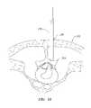
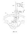
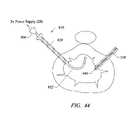
- the instant inventionprovides methods for decompressing nerve roots by ablation, shrinkage, or stiffening of disc tissue during a percutaneous procedure, wherein the volume of the disc is decreased and discogenic pain is alleviated.
- the present inventionprovides systems, apparatus, and methods for selectively applying electrical energy to structures within a patient's body, such as the inter-vertebral disc.
- the systems and methods of the present inventionare useful for shrinkage, ablation, stiffening, resection, aspiration, and/or hemostasis of tissue and other body structures in open and endoscopic spine surgery.
- the present inventionincludes methods and apparatus for debulking, ablating, stiffening, shrinking, or otherwise treating tissue of inter-vertebral discs.
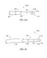
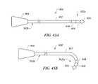
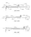
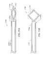
- the present inventionfurther relates to an electrosurgical probe including an elongated shaft having first and second curves in the distal end portion of the shaft, wherein the shaft can be rotated within an inter-vertebral disc to contact fresh tissue of the nucleus pulposus.
- the present inventionalso relates to an electrosurgical probe including an elongated shaft, wherein the shaft distal end can be guided to a specific target site within a disc, and the shaft distal end is adapted for localized ablation of targeted disc tissue.
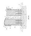
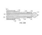
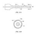
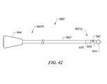
- the present inventionfurther relates to a probe having an elongated shaft, wherein the shaft includes an active electrode, an insulating collar, and an outer shield, and wherein the active electrode includes a head having an apical spike and a cusp.
- the present inventionstill further relates to a method for ablating disc tissue with an electrosurgical probe, wherein the probe includes an elongated shaft, and the shaft distal end is guided to a specific target site within a disc.
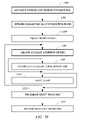
- the present inventionprovides a method of treating a herniated inter-vertebral disc.
- the methodcomprises positioning at least one active electrode within the inter-vertebral disc.
- High frequency voltageis applied between the active electrode(s) and one or more return electrode(s) to debulk, ablate, coagulate and/or shrink at least a portion of the nucleus pulposus and/or the annulus fibrosus.
- the high frequency voltageeffects a controlled depth of thermal heating to reduce the water content of the nucleus pulposus, thereby debulking the nucleus pulposus and reducing the internal pressure on the annulus fibrosus.
- an extraneous electrically conductive fluidsuch as isotonic saline or an electrically conductive gel, is delivered to the target site within the inter-vertebral disc prior to delivery of the high frequency voltage.
- the electrically conductive fluidmay fill the entire target region such that the active electrode(s) are submerged throughout the procedure.
- the electrically conductive fluid in the patient's disce.g., the nucleus pulposus
- the extraneous electrically conductive fluide.g., saline
- an initial amount of electrically conductive fluidis provided to initiate the requisite conditions (e.g., formation of a plasma layer) for ablation. Thereafter, the intrinsic electrically conductive fluid already present in the patient's tissue is used to sustain these conditions.
- the present inventionprovides a method of treating a disc having a contained herniation or fissure.
- the methodcomprises introducing an electrosurgical instrument into the patient's inter-vertebral disc either percutaneously or through an open procedure.
- the instrumentis steered or otherwise guided into close proximity to the contained herniation or fissure and a high frequency voltage is applied between an active electrode and a return electrode so as to debulk the nucleus pulposus adjacent the contained herniation or fissure.
- an electrically conductive fluidis delivered into the inter-vertebral disc prior to applying the high frequency voltage, to ensure that sufficient electrically conductive fluid exists for plasma formation and to conduct electric current between the active and return electrodes.
- the conductive fluidcan be delivered to the target site during the procedure.
- heating the nucleus pulposusdebulks the nucleus pulposus, and reduces the size of the disc so as to decrease the pressure on the affected nerve root and alleviate neck and back pain.
- an ionized plasmais formed and charged particles (e.g., electrons) cause the molecular breakdown or disintegration of several cell layers of the nucleus pulposus.
- This molecular dissociationis accompanied by the volumetric removal of the tissue.
- This processcan be precisely controlled to effect the volumetric removal of tissue as thin as 10 microns to 150 microns with minimal heating of, or damage to, surrounding or underlying tissue structures.
- U.S. Pat. No. 5,697,882the complete disclosure of which is incorporated herein by reference.
- the active electrode(s)may comprise a single active electrode, or an electrode array, extending from an electrically insulating support member, typically made of an inorganic material such as a ceramic, a silicone rubber, or a glass.
- the active electrodeusually has a smaller exposed surface area than the return electrode, such that the current densities are much higher at the active electrode than at the return electrode.
- the return electrodehas a relatively large, smooth surface extending around the instrument shaft to reduce current densities, thereby minimizing damage to adjacent tissue.
- the present inventionprovides a method of treating an inter-vertebral disc, the method comprising contacting at least a first region of the inter-vertebral disc with at least one active electrode of an electrosurgical system.
- the at least one active electrodemay be disposed on the distal end portion of a shaft of the electrosurgical system.
- a first high frequency voltageis applied between the active electrode(s) and one or more return electrode(s) such that at least a portion of the nucleus pulposus is ablated, and the volume of the disc's nucleus pulposus is decreased.
- disc tissue in the vicinity of the channelmay be coagulated, made necrotic, or made to sustain controlled thermal damage by applying a second high frequency voltage, wherein the second high frequency voltage may have different parameters as compared with the first high frequency voltage.
- the second high frequency voltagemay be applied in a sub-ablation mode to stiffen or shrink disc tissue in the vicinity of the channel.
- the present inventionprovides a method for treating an inter-vertebral disc, wherein the method involves providing an electrosurgical system including a probe having a shaft and a handle, the shaft having at least one active electrode located on the distal end portion of the shaft, and wherein the shaft distal end portion includes a pre-defined bias.
- the methodfurther involves inserting the shaft distal end portion within the disc, and ablating at least a portion of the nucleus pulposus tissue from the disc such that the volume of the disc is decreased with minimal or no collateral damage to non-target tissue within the disc.
- the ablating stepinvolves applying a high frequency voltage between the at least one active electrode and at least one return electrode.
- the high frequency voltageis sufficient to vaporize an electrically conductive fluid (e.g., a gel, isotonic saline, and/or tissue fluid) located between the at least one active electrode and the target tissue.
- an electrically conductive fluide.g., a gel, isotonic saline, and/or tissue fluid
- a plasmais formed, and charged particles (e.g., electrons) are accelerated towards the nucleus pulposus to cause the molecular dissociation of nucleus pulposus tissue at the site to be ablated. This molecular dissociation is accompanied by the volumetric removal of disc tissue at the target site.
- inserting the shaft distal end portion in the discinvolves advancing the shaft distal end portion via an introducer needle, the introducer needle having a lumen and a needle distal end, such that when the shaft distal end portion is advanced distally beyond the needle distal end, the at least one active electrode does not make contact with the needle distal end.
- One or more stages in the treatment or proceduremay be performed under fluoroscopy to allow visualization of the shaft within the disc to be treated. Visualization of the shaft may be enhanced by inclusion of a radiopaque tracking device on the distal end of the shaft.
- the depth of penetration of the shaft into a disccan be monitored by one or more depth markings on the shaft.
- the methodfurther comprises retracting the shaft distal end portion proximally within the lumen of the introducer needle, wherein the at least one active electrode does not make contact with the needle distal end.
- a probe of the electrosurgical systemincludes a shield, and a distal insulating collar.
- the at least one active electrodeincludes an apical spike and a cusp. Applicants have found that an active electrode having an apical spike and a cusp promotes high current density in the vicinity of the active electrode.
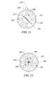
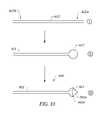
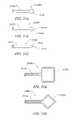
- an electrode for a medical instrumentwherein the electrode comprises an electrode filament and a distal electrode head in the form of a loop.
- the loopis formed by folding a length of insulated wire, separating the folded wire at the distal end portion of the folded wire to form the loop, and removing a layer of insulation from the wire in the region of the loop.
- the layer of insulationmay comprise a polyimide.
- the loopis substantially oval or substantially circular.
- the loopis substantially square or rectangular, and is formed by making a plurality of folds in a length of wire.
- the filamentcomprises a pair of juxtaposed wires resulting from folding the length of wire.
- the loopmay comprise a metal such as platinum, stainless steel, molybdenum, tungsten, titanium, molybdenum, nickel, iridium, or their alloys.
- an electrode for an electrosurgical probemay be constructed by forming an elongate void in a distal portion of a wire, and opening the void to form a loop, wherein the loop comprises an apical electrode head.
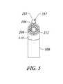
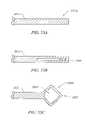
- an electrosurgical probeincluding a shaft having a shaft distal end, and an electrode assembly disposed at the shaft distal end.
- the electrode assemblycomprising an active electrode having a distal electrode head in the form of a loop.
- the shaft distal end and the electrode assemblyare adapted for passage through a lumen of an introducer device, such as a hypodermic needle.
- the probeis capable of ablating tissue in an ablation mode, and for modifying tissue in a sub-ablation mode.
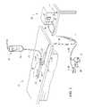
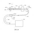
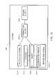
- an electrosurgical apparatusincluding a probe having a shaft distal end, an introducer needle having a lumen therethrough, and a positioning unit.
- the introducer needleis adapted for passage of the shaft distal end therethrough.
- the probeincludes an electrode assembly disposed at the shaft distal end, and is adapted for treating tissue, e.g., tissue within an inter-vertebral disc. Treatment may include ablation or modification of disc tissue by application of a high frequency voltage from a power supply operating in the ablation mode or the sub-ablation mode. Modification of the disc tissue may involve coagulation, shrinkage, or stiffening of a target tissue.
- the positioning unitis adapted for monitoring a location of the probe relative to the introducer needle.
- the positioning unitis further adapted for advancing and retracting the introducer needle relative to the probe, and for locking the probe in one or more positions relative to the introducer needle.
- the introducer needleincludes at least one depth marking for monitoring a depth of penetration of the introducer needle into a patient's body, and an introducer stop unit for limiting the depth of penetration of the introducer needle into the patient's body.
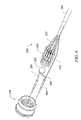
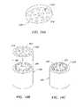
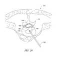
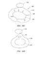
- the active electrode headPrior to firing the probe for treatment of a target tissue, the active electrode head protrudes from the distal end of the introducer needle and adopts the expanded configuration. In the expanded configuration, a larger volume of tissue can be treated by the probe for a given amount of axial and rotational movement of the probe.
- the active electrode headcomprises a spring-like material biased towards the expanded configuration.
- the active electrode headmay comprise a shape memory alloy (SMA).
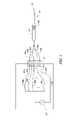
- an apparatusincluding an electrosurgical probe and an introducer device, wherein the probe includes a shaft, an electrically insulating spacer disposed at the distal end of the shaft, and an active electrode disposed on the spacer.
- the introducer devicecomprises an electrically conducting material and includes a lumen therethrough, the lumen adapted for accommodating the shaft.
- the shaftsimilarly comprises an electrically conducting material, and the shaft makes electrical contact with the introducer device when the shaft is engaged within the lumen.
- the shaft and the active electrodeare independently coupled to a high frequency power supply. When the shaft is engaged within the introducer device, and a voltage is applied from the power supply, the shaft and introducer device in combination serve as return electrode for the apparatus.
- a proximal portion of the introducer devicehas a thin external coating of an electrically insulating material.
- the external coatingmay comprise a polymeric material, such as a Parylene (Union Carbide).
- the external coatingmay be deposited by gas phase polymerization to give a uniform, heat-resistant, biocompatible, pinhole-free layer.
- using the introducer device in combination with the shaft as return electrodeallows construction of a narrower apparatus (i.e., a probe engaged within an introducer device) as well as other advantages, as compared with conventional probe/introducer device combinations.
- a narrower apparatusi.e., a probe engaged within an introducer device
- prior art devicesuse an insulating layer on the shaft to prevent arcing between the shaft and the introducer device, and, in some cases a protective layer covers the insulating layer to protect the insulating layer from skinning as the shaft is passed within the introducer device.
- the introducer deviceas a return electrode, both the insulating layer on the shaft and the protective layer are omitted.
- the external coating on the introducer device of the inventionis typically thinner than the insulating layer on the shaft of many prior art devices, thereby further reducing the overall diameter of the probe/introducer combination.
- An electrosurgical probe/introducer combination having a narrower diameteroffers advantages in a broad range of procedures.
- the inventionprovides an apparatus including an electrosurgical probe and an introducer device, wherein a return electrode of the apparatus comprises a shaft of the probe in combination with the introducer device, and wherein the apparatus requires a shorter length of the probe to protrude from the distal end of the introducer device for firing the probe, as compared with apparatus of the prior art.
- a return electrode of the apparatuscomprises a shaft of the probe in combination with the introducer device
- the apparatusrequires a shorter length of the probe to protrude from the distal end of the introducer device for firing the probe, as compared with apparatus of the prior art.
- a method for treating an inter-vertebral disccomprises introducing an introducer needle into the disc of a patient. Thereafter, an electrode assembly of a probe is positioned within the disc by passage through the needle lumen. The electrode assembly comprises a distal active electrode disposed on an electrically insulating spacer. The introducer needle is retracted, by actuation of a positioning unit, in order to expose a distal portion of the probe. The extent to which the electrode assembly protrudes distally from the introducer needle is monitored, and if necessary restricted, via the positioning unit.
- a high frequency voltagemay be applied to the probe via a high frequency power supply operating in the ablation mode or the sub-ablation mode. In this manner, target tissue within the disc can be ablated, coagulated, shrunk (contracted), or stiffened.
- FIG. 1is a perspective view of an electrosurgical system incorporating a power supply and an electrosurgical probe for tissue ablation, resection, incision, contraction and for vessel hemostasis according to the present invention
- FIG. 2schematically illustrates one embodiment of a power supply according to the present invention
- FIG. 3illustrates an electrosurgical system incorporating a plurality of active electrodes and associated current limiting elements
- FIG. 4is a side view of an electrosurgical probe according to the present invention.
- FIG. 5is a view of the distal end portion of the probe of FIG. 4
- FIG. 6is an exploded view of a proximal portion of an electrosurgical
- FIGS. 7A and 7Bare perspective and end views, respectively, of an alternative electrosurgical probe incorporating an inner fluid lumen
- FIGS. 8A-8Care cross-sectional views of the distal portions of three different embodiments of an electrosurgical probe according to the present invention.
- FIGS. 9-12are end views of alternative embodiments of the probe of FIG. 4 , incorporating aspiration electrode(s);
- FIG. 13is a side view of the distal portion of the shaft of an electrosurgical probe, according to one embodiment of the invention.
- FIGS. 14A-14Cillustrate an alternative embodiment incorporating a screen electrode
- FIGS. 15A-15Dillustrate four embodiments of electrosurgical probes specifically designed for treating spinal defects
- FIG. 16illustrates an electrosurgical system incorporating a dispersive return pad for monopolar and/or bipolar operations
- FIG. 17illustrates a catheter system for electrosurgical treatment of inter-vertebral discs according to the present invention
- FIGS. 18-22illustrate a method of performing a microendoscopic discectomy according to the principles of the present invention
- FIGS. 23-25illustrates another method of treating a spinal disc with one of the catheters or probes of the present invention
- FIG. 26Ais a side view of an electrosurgical probe according to the invention.
- FIG. 26Bis a side view of the distal end portion of the electrosurgical probe of FIG. 26A ;
- FIG. 27Ais a side view of an electrosurgical probe having a curved shaft
- FIG. 27Bis a side view of the distal end portion of the curved shaft of FIG. 27A , with the shaft distal end portion within an introducer device;
- FIG. 28Ais a side view of the distal end portion of an electrosurgical probe showing an active electrode having an apical spike and an equatorial cusp;
- FIG. 28Bis a cross-sectional view of the distal end portion of the electrosurgical probe of FIG. 28A ;
- FIG. 29is a side view of the distal end portion a shaft of an electrosurgical probe, indicating the position of a first curve and a second curve in relation to the head of the active electrode;
- FIG. 30Ashows the distal end portion of the shaft of an electrosurgical probe extended distally from an introducer needle
- FIG. 30Billustrates the position of the active electrode in relation to the inner wall of the introducer needle upon retraction of the active electrode within the introducer needle
- FIGS. 31A , 31 Bshow a side view and an end view, respectively, of a curved shaft of an electrosurgical probe, in relation to an introducer needle;
- FIG. 32Ashows the proximal end portion of the shaft of an electrosurgical probe, wherein the shaft includes a plurality of depth markings;
- FIG. 32Bshows the proximal end portion of the shaft of an electrosurgical probe, wherein the shaft includes a mechanical stop
- FIG. 33illustrates stages in manufacture of an active electrode of an electrosurgical probe of the present invention
- FIG. 34schematically represents a series of steps involved in a method of making a probe shaft of the present invention
- FIG. 35schematically represents a series of steps involved in a method of making an electrosurgical probe of the present invention
- FIG. 36Aschematically represents a normal inter-vertebral disc in relation to the spinal cord
- FIG. 36Bschematically represents an inter-vertebral disc exhibiting a protrusion of the nucleus pulposus and a concomitant distortion of the annulus fibrosus;
- FIG. 36Cschematically represents an inter-vertebral disc exhibiting a plurality of fissures within the annulus fibrosus and a concomitant distortion of the annulus fibrosus;
- FIG. 36Dschematically represents an inter-vertebral disc exhibiting fragmentation of the nucleus pulposus and a concomitant distortion of the annulus fibrosus;
- FIG. 37schematically represents translation of a curved shaft of an electrosurgical probe within the nucleus pulposus for treatment of an inter-vertebral disc
- FIG. 38shows a shaft of an electrosurgical probe within an inter-vertebral disc, wherein the shaft distal end is targeted to a specific site within the disc;
- FIG. 39schematically represents a series of steps involved in a method of ablating disc tissue according to the present invention.
- FIG. 40schematically represents a series of steps involved in a method of guiding an electrosurgical probe to a target site within an inter-vertebral disc for ablation of targeted disc tissue, according to another embodiment of the invention
- FIG. 41shows treatment of an inter-vertebral disc using an electrosurgical probe and a separately introduced ancillary device, according to another embodiment of the invention.
- FIG. 42is a side view of an electrosurgical probe having a tracking device
- FIG. 43Ashows a steerable electrosurgical probe wherein the shaft of the probe assumes a substantially linear configuration
- FIG. 43Bshows the steerable electrosurgical probe of FIG. 43A , wherein the shaft distal end of the probe adopts a bent configuration
- FIG. 44shows a steerable electrosurgical probe and an ancillary device inserted within the nucleus pulposus of an inter-vertebral disc;
- FIG. 45is a block diagram representing an electrosurgical system, according to another embodiment of the invention.
- FIG. 46is a block diagram representing an introducer unit of an electrosurgical apparatus, according to one embodiment of the invention.
- FIGS. 47A and 47Beach represents an electrosurgical probe, according to the invention.
- FIG. 48schematically represents an electrosurgical system, according to one embodiment of the invention.
- FIGS. 49A-Ceach schematically represent an electrosurgical probe in a different position relative to an introducer device, according to the invention.
- FIG. 50is a partial longitudinal section of the distal portion of an electrosurgical probe, according to one embodiment of the invention.
- FIGS. 51A-Ceach schematically represents an active electrode for a medical instrument, according to three different embodiments.
- FIGS. 52A-Beach schematically represents an active electrode for a medical instrument, according to two different embodiments of the invention.
- FIGS. 53A-Crepresent stages in forming an active electrode loop from a wire or filament, according to one embodiment of the invention.
- FIG. 54schematically represents a procedure for electrosurgical treatment of a cervical inter-vertebral disc, according to one embodiment of the invention.
- FIGS. 55A-Ceach schematically represent positioning an electrosurgical apparatus within an inter-vertebral disc, according to the invention.
- FIG. 56is a block diagram representing an electrosurgical system, according to another embodiment of the invention.
- FIGS. 57A-Dschematically represent an electrosurgical apparatus including an introducer device, according to the invention.
- FIGS. 58A-Cschematically represent an expandable electrode, according to another embodiment of the invention.
- FIGS. 59A and 59Bschematically represent an expandable electrode in the unexpanded and expanded configurations, respectively, according to another embodiment of the invention.
- FIG. 60schematically represents steps involved in a method for treating an inter-vertebral disc, according to another embodiment of the invention.
- the present inventionprovides systems and methods for selectively applying electrical energy to a target location within or on a patient's body, particularly including support tissue or other body structures in the spine.
- the inventionmay be used for performing a broad range of procedures, including treating interspinous tissue and degenerative discs, laminectomy/discectomy procedures for treating herniated discs, decompressive laminectomy for stenosis in the lumbosacral and cervical spine, localized tears or fissures in the annulus, nucleotomy, disc fusion procedures, medial facetectomy, posterior lumbosacral and cervical spine fuisions, treatment of scoliosis associated with vertebral disease, foraminotomies to remove the roof of the inter-vertebral foramina to relieve nerve root compression, and anterior cervical and lumbar discectomies.
- These proceduresmay be performed through open procedures, or using minimally invasive techniques, such as thoracoscopy, arthroscopy, laparascopy or the like.
- the present inventioninvolves techniques for treating disc abnormalities with RF energy.
- RF energyis used to ablate, debulk and/or stiffen the tissue structure of the disc to reduce the volume of the disc, thereby relieving neck and back pain.
- spinal disc tissueis volumetrically removed or ablated to form holes, channels, divots or other spaces within the disc.
- a high frequency voltage differenceis applied between one or more active electrode(s) and one or more return electrode(s) to develop high electric field intensities in the vicinity of the target tissue.
- the high electric field intensities adjacent the active electrode(s)lead to electric field induced molecular breakdown of target tissue through molecular dissociation (rather than thermal evaporation or carbonization).
- tissue structureis volumetrically removed through molecular disintegration of larger organic molecules into smaller molecules and/or atoms, such as hydrogen, oxygen, oxides of carbon, hydrocarbons and nitrogen compounds.
- This molecular disintegrationcompletely removes the tissue structure, as opposed to dehydrating the tissue material by the removal of water from within the cells of the tissue and extracellular fluids, as is typically the case with electrosurgical desiccation of the prior art.
- the present inventionalso involves a system and method for treating the interspinous tissue (e.g., tendons, cartilage, synovial tissue between the vertebrae, and other support tissue within and surrounding the vertebral column).
- RF energyis used to heat and shrink the interspinous tissue to stabilize the vertebral column and reduce pain in the back and neck.
- an active electrodeis positioned adjacent the interspinous tissue and the interspinous tissue is heated, preferably with RF energy, to a sufficient temperature to shrink the interspinous tissue.
- a high frequency voltage differenceis applied between one or more active electrode(s) and one or more return electrode(s) to develop high electric field intensities in the vicinity of the target tissue to controllably heat the target tissue.
- the high electric field intensitiesmay be generated by applying a high frequency voltage that is sufficient to vaporize an electrically conductive fluid over at least a portion of the active electrode(s) in the region between the distal tip of the active electrode(s) and the target tissue.
- the electrically conductive fluidmay be a gas or liquid, such as isotonic saline, blood, extracellular or intracellular fluid, delivered to, or already present at, the target site, or a viscous fluid, such as a gel, applied to the target site. Since the vapor layer or vaporized region has a relatively high electrical impedance, it minimizes the current flow into the electrically conductive fluid.
- Coblatione®This ionization, under the conditions described herein, induces the discharge of energetic electrons and photons from the vapor layer and to the surface of the target tissue.
- Coblatione®A more detailed description of this phenomenon, termed Coblatione® can be found in commonly assigned U.S. Pat. No. 5,697,882 the complete disclosure of which is incorporated herein by reference.
- Applicantbelieves that the principal mechanism of tissue removal in the Coblationg® process of the present invention involves energetic electrons or ions that have been energized in a plasma adjacent to the active electrode(s).
- a liquidis heated enough that atoms vaporize off the surface faster than they recondense, a gas is formed.
- the gasis heated enough that the atoms collide with each other and knock their electrons off in the process, an ionized gas or plasma is formed (the so-called “fourth state of matter”).
- a more complete description of plasmacan be found in Plasma Physics , by R. J. Goldston and P. H. Rutherford of the Plasma Physics Laboratory of Princeton University (1995), the complete disclosure of which is incorporated herein by reference.
- the electron mean free pathincreases to enable subsequently injected electrons to cause impact ionization within these regions of low density (i.e., vapor layers or bubbles).
- the ionic particles in the plasma layerhave sufficient energy, they accelerate towards the target tissue.
- Energy evolved by the energetic electronse.g., 3.5 eV to 5 eV
- Plasmasmay be formed by heating a gas and ionizing the gas by driving an electric current through it, or by transmitting radio waves into the gas.
- these methods of plasma formationgive energy to free electrons in the plasma directly, and then electron-atom collisions liberate more electrons, and the process cascades until the desired degree of ionization is achieved.
- the electronscarry the electrical current or absorb the radio waves and, therefore, are hotter than the ions.
- the electronswhich are carried away from the tissue towards the return electrode, carry most of the plasma's heat with them, allowing the ions to break apart the tissue molecules in a substantially non-thermal manner.
- the present inventionapplies high frequency (RF) electrical energy in an electrically conducting media environment to shrink or remove (i.e., resect, cut, or ablate) a tissue structure and to seal transected vessels within the region of the target tissue.
- RFhigh frequency
- the present inventionmay also be useful for sealing larger arterial vessels, e.g., on the order of about 1 mm in diameter.
- a high frequency power supplyhaving an ablation mode, wherein a first voltage is applied to an active electrode sufficient to effect molecular dissociation or disintegration of the tissue, and a coagulation mode, wherein a second, lower voltage is applied to an active electrode (either the same or a different electrode) sufficient to heat, shrink, and/or achieve hemostasis of severed vessels within the tissue.
- an electrosurgical instrumentis provided having one or more coagulation electrode(s) configured for sealing a severed vessel, such as an arterial vessel, and one or more active electrodes configured for either contracting the collagen fibers within the tissue or removing (ablating) the tissue, e.g., by applying sufficient energy to the tissue to effect molecular dissociation.
- the coagulation electrode(s)may be configured such that a single voltage can be applied to coagulate with the coagulation electrode(s), and to ablate or shrink with the active electrode(s).
- the power supplyis combined with the coagulation instrument such that the coagulation electrode is used when the power supply is in the coagulation mode (low voltage), and the active electrode(s) are used when the power supply is in the ablation mode (higher voltage).
- one or more active electrodesare brought into close proximity to tissue at a target site, and the power supply is activated in the ablation mode such that sufficient voltage is applied between the active electrodes and the return electrode to volumetrically remove the tissue through molecular dissociation, as described below.
- the power supplyis activated in the ablation mode such that sufficient voltage is applied between the active electrodes and the return electrode to volumetrically remove the tissue through molecular dissociation, as described below.
- vessels within the tissuewill be severed. Smaller vessels will be automatically sealed with the system and method of the present invention. Larger vessels, and those with a higher flow rate, such as arterial vessels, may not be automatically sealed in the ablation mode. In these cases, the severed vessels may be sealed by activating a control (e.g., a foot pedal) to reduce the voltage of the power supply into the coagulation mode.
- a controle.g., a foot pedal
- the active electrodesmay be pressed against the severed vessel to provide sealing and/or coagulation of the vessel.
- a coagulation electrode located on the same or a different instrumentmay be pressed against the severed vessel.
- the present inventionmay be used to shrink or contract collagen containing connective tissue which supports the vertebral column, or collagen containing connective tissue within an inter-vertebral disc.
- the RF energyheats the tissue directly by virtue of the electrical current flow therethrough, and/or indirectly through the exposure of the tissue to fluid heated by RF energy, to elevate the tissue temperature from normal body temperatures (e.g., 37° C.) to temperatures in the range of 45° C. to 90° C., preferably in the range from about 60° C. to 70° C.
- Thermal shrinkage of collagen fibersoccurs within a small temperature range which, for mammalian collagen is in the range of from about 60° C. to 70° C.
- the preferred depth of heating to effect the shrinkage of collagen in the heated regioni.e., the depth to which the tissue is elevated to temperatures between 60° C. to 70° C.
- the depth of heatingis usually in the range from 1.0 mm to 5.0 mm.
- the tissueis purposely damaged in a thermal heating mode to create necrosed or scarred tissue at the tissue surface.
- the high frequency voltage in the thermal heating modeis below the threshold of ablation as described above, but sufficient to cause some thermal damage to the tissue immediately surrounding the electrodes without vaporizing or otherwise debulking this tissue in situ.
- the voltage required for this thermal damagewill partly depend on the electrode configurations, the conductivity of the area immediately surrounding the electrodes, the time period for which the voltage is applied, and the depth of tissue damage desired.
- the voltage level for thermal heatingwill usually be in the range of about 20 volts RMS to 300 volts RMS, and more typically about 60 volts RMS to 200 volts RMS.
- the peak-to-peak voltages for thermal heating with a square wave form having a crest factor of about 2are typically in the range of about 40 volts peak-to-peak to 600 volts peak-to-peak, preferably about 120 volts peak-to-peak to 400 volts peak-to-peak.
- capacitors or other electrical elementsmay be used to increase the crest factor up to 10. The higher the voltage is within this range, the less time required. If the voltage is too high, however, the surface tissue may be vaporized, debulked or ablated, which is generally undesirable for certain applications.
- the present inventionmay be used for treating degenerative discs having fissures or tears.
- the active and return electrode(s)are positioned in or around the inner wall of the annulus fibrosus such that the active electrode is adjacent to the fissure.
- High frequency voltageis applied between the active and return electrodes to heat the tissue adjacent to the fissure, to shrink the collagen fibers, to create a seal or weld within the inner wall, thereby helping to close the fissure in the annulus fibrosus.
- the return electrodewill typically be positioned proximally from the active electrode(s) on the instrument shaft, and an electrically conductive fluid will be supplied to provide a current path between the active and return electrodes.
- the disc tissuemay complete this electrically conductive path.
- the present inventionis also useful for removing or ablating tissue around nerves, such as spinal, peripheral, or cranial nerves.
- nervessuch as spinal, peripheral, or cranial nerves.
- One of the significant drawbacks with the prior art shavers or microdebriders, conventional electrosurgical devices, and lasersis that these devices do not differentiate between the target tissue and the surrounding nerves or bone. Therefore, the surgeon must be extremely careful during these procedures to avoid damage to the bone or nerves within and around the target site.
- the Coblation® process for removing tissueavoids damage to non-target tissue, or results in extremely small depths of collateral tissue damage, as discussed above. This allows the surgeon to remove tissue close to a nerve without damaging the nerve.
- Peripheral nervesusually comprise a connective tissue sheath, or epineurium, enclosing the bundles of nerve fibers, each bundle being surrounded by its own sheath of connective tissue (the perineurium) to protect these nerve fibers.
- the outer protective tissue sheath or epineuriumtypically comprises a fatty material having substantially different electrical properties than the normal target tissue, such as collagen containing connective tissue in or around the vertebral column.
- the system of the present inventionmeasures the electrical properties of the tissue at the tip of the probe with one or more sensing electrode(s). These electrical properties may include electrical conductivity at one, several, or a range of frequencies (e.g., in the range from 1 kHz to 100 MHz), dielectric constant, capacitance, or combinations of these. In this embodiment, an audible signal may be produced when the sensing electrode(s) at the tip of the probe detects the fatty material surrounding a nerve.
- direct feedback controlcan be provided to supply power to the active electrode(s), either individually or to the complete array of electrodes, only if and when the tissue encountered at the tip or working end of the probe is normal tissue based on the measured electrical properties.
- the current limiting elementsare configured such that the active electrodes will shut down or turn off when the electrical impedance reaches a threshold level.
- a threshold levelis set to the impedance of the fatty material surrounding peripheral nerves, the active electrodes will shut off whenever they come in contact with, or in close proximity to, nerves.
- other active electrodes of an electrode arraywhich are in contact with or in close proximity to “normal” target tissue, will continue to conduct electric current to the return electrode.
- This selective ablation or removal of lower impedance tissuein combination with the Coblation® mechanism of the present invention, allows the surgeon to precisely remove tissue around nerves or bone. Applicant has found that the present invention is capable of volumetrically removing tissue closely adjacent to nerves without impairing the function of the nerves, and without significantly damaging the epineurium.
- the Coblation® mechanism of the present inventioncan be manipulated to ablate or remove certain tissue structures, while having little effect on other tissue structures.
- the present inventionuses a technique of vaporizing electrically conductive fluid to form a plasma layer or pocket around the active electrode(s), and then inducing the discharge of energy from this plasma or vapor layer to break the molecular bonds of the tissue structure. Based on initial experiments, applicants believe that the free electrons within the ionized vapor layer are accelerated in the high electric fields near the electrode tip(s).
- the electron mean free pathincreases to enable subsequently injected electrons to cause impact ionization within these regions of low density (i.e., vapor layers or bubbles).
- Energy evolved by the energetic electronse.g., 4 eV to 5 eV
- the energy evolved by the energetic electronsmay be varied by adjusting a variety of factors, such as: the number of active electrodes; electrode size and spacing; electrode surface area; asperities and sharp edges on the electrode surfaces; electrode materials; applied voltage and power; current limiting means, such as inductors; electrical conductivity of the fluid in contact with the electrodes; density of the fluid; and other factors. Accordingly, these factors can be manipulated to control the energy level of the excited electrons. Since different tissue structures have different molecular bonds, the present invention can be configured to break the molecular bonds of certain tissue, while having too low an energy to break the molecular bonds of other tissue.
- fatty tissuee.g., adipose tissue
- adipose tissuehas double bonds that require a substantially higher energy level than 4 eV to 5 eV to break (typically on the order of about 8 eV).
- the present inventionin its current configuration generally does not ablate or remove such fatty tissue.
- the present inventionmay be used to effectively ablate cells to release the inner fat content in a liquid form.
- factorsmay be changed such that these double bonds can also be broken in a similar fashion as the single bonds (e.g., by increasing voltage or changing the electrode configuration to increase the current density at the electrode tips).
- a more complete description of this phenomenoncan be found in co-pending U.S. patent application Ser. No. 09/032,375, filed Feb. 27, 1998 (Attorney Docket No. CB-3), the complete disclosure of which is incorporated herein by reference.
- the present inventionprovides systems, apparatus and methods for selectively removing tumors, e.g., facial tumors, or other undesirable body structures, while minimizing the spread of viable cells from the tumor.
- Conventional techniques for removing such tumorsgenerally result in the production of smoke in the surgical setting, termed an electrosurgical or laser plume, which can spread intact, viable cells, bacteria, or viral particles from the tumor or lesion to the surgical team, or to other portions of the patient's body.
- This potential spread of viable cells or particleshas resulted in increased concerns over the proliferation of certain debilitating and fatal diseases, such as hepatitis, herpes, HIV, and papillomavirus.
- high frequency voltageis applied between the active electrode(s) and one or more return electrode(s) to volumetrically remove at least a portion of the tissue cells in the tumor through the dissociation or disintegration of organic molecules into non-viable atoms and molecules.
- the present inventionconverts the cellular components of solid tissue into non-condensable gases that are no longer intact or viable, and thus, incapable of spreading viable tumor cells, bacteria, or viral particles to other portions of the patient's body or to the surgical staff.
- the high frequency voltageis preferably selected to effect controlled removal of target tissue while minimizing substantial tissue necrosis to surrounding or underlying tissue.
- the electrosurgical probe or catheter of the present inventioncan comprise a shaft or a handpiece having a proximal end and a distal end which supports one or more active electrode(s).
- the shaft or handpiecemay assume a wide variety of configurations, with the primary purpose being to mechanically support the active electrode and permit the treating physician to manipulate the electrode from a proximal end of the shaft.
- the shaftmay be rigid or flexible, with flexible shafts optionally being combined with a generally rigid external tube for mechanical support. Flexible shafts may be combined with pull wires, shape memory actuators, and other known mechanisms,for effecting selective deflection of the distal end of the shaft to facilitate positioning of the electrode(s) or electrode array.
- the shaftmay include a plurality of wires or other conductive elements running axially therethrough to permit connection of the electrode array to a connector at the proximal end of the shaft.
- the shaftwill have a suitable diameter and length to allow the surgeon to reach the target site (e.g., a disc or vertebra) by delivering the shaft through the thoracic cavity, the abdomen or the like.
- the shaftwill usually have a length in the range of about 5.0 cm to 30.0 cm, and a diameter in the range of about 0.2 mm to about 20 mm.
- the shaftmay be delivered directly through the patient's back in a posterior approach, which would considerably reduce the required length of the shaft.
- the target tissuemay be accessed in a posterior approach from the back of the neck.
- the shaftmay be introduced through rigid or flexible endoscopes, or via other introducer devices (e.g., an introducer needle).
- the shaftmay be a flexible catheter that is introduced through a percutaneous penetration in the patient. Specific shaft designs will be described in detail in connection with the figures hereinafter.
- the probemay comprise a long, thin shaft (e.g., on the order of about 1 mm or less in diameter) that can be percutaneously introduced through the patient's back directly into the spine.
- the shaftincludes one or more active electrode(s) for applying electrical energy to tissues of the vertebral column.
- the shaftmay include one or more return electrode(s), or the return electrode may be positioned on the patient's back, as a dispersive pad. In either embodiment, sufficient electrical energy is applied to the active electrode(s) to either shrink the collagen fibers within the spinal disc, to ablate tissue within the disc, or to shrink supporting tissue surrounding the vertebrae.
- the electrosurgical instrumentmay also be a catheter that is delivered percutaneously and/or endoluminally into the patient by insertion through a conventional or specialized guide catheter, or the invention may include a catheter having an active electrode or electrode array integral with its distal end.
- the catheter shaftmay be rigid or flexible, with flexible shafts optionally being combined with a generally rigid external tube for mechanical support. Flexible shafts may be combined with pull wires, shape memory actuators, and other known mechanisms for effecting selective deflection of the distal end of the shaft to facilitate positioning of the electrode or electrode array.
- the catheter shaftwill usually include a plurality of wires or other conductive elements running axially therethrough to permit connection of the electrode or electrode array and the return electrode to a connector at the proximal end of the catheter shaft.
- the catheter shaftmay include a guide wire for guiding the catheter to the target site, or the catheter may comprise a steerable guide catheter.
- the cathetermay also include a substantially rigid distal end portion to increase the torque control of the distal end portion as the catheter is advanced further into the patient's body.
- the active electrode(s)are preferably supported within or by an electrically insulating support positioned near the distal end of the instrument shaft.
- the return electrodemay be located on the instrument shaft, on another instrument, or on the external surface of the patient (i.e., a dispersive pad).
- a dispersive padlocated on the instrument shaft, on another instrument, or on the external surface of the patient (i.e., a dispersive pad).
- the return electrodeis preferably either integrated with the instrument body, or another instrument located in close proximity thereto.
- the proximal end of the instrument(s)include the appropriate electrical connections for coupling the return electrode(s) and the active electrode(s) to a high frequency power supply, such as an electrosurgical generator.
- the active electrode(s)have an active portion or surface with surface geometries shaped to promote relatively high electric field intensity and associated current density along the leading edges of the electrodes. Suitable surface geometries may be obtained by creating electrode shapes that include preferential sharp edges, or by creating asperities or other surface roughness on the active surface(s) of the electrodes. Electrode shapes according to the present invention can include the use of formed wire (e.g., by drawing round wire through a shaping die) to form electrodes with a variety of cross-sectional shapes, such as square, rectangular, L or V shaped, or the like. Electrode edges may also be created by removing a portion of the elongate metal electrode to reshape the cross-section.
- materialcan be ground along the length of a round or hollow wire electrode to form D or C shaped wires, respectively, with edges facing in the cutting direction.
- materialcan be removed at closely spaced intervals along the electrode length to form transverse grooves, slots, threads or the like along the electrodes.
- the active electrode surface(s)may be modified through chemical, electrochemical or abrasive methods to create a multiplicity of surface asperities on the electrode surface. These surface asperities will promote high electric field intensities between the active electrode surface(s) and the target tissue to facilitate ablation or cutting of the tissue.
- surface asperitiesmay be created by etching the active electrodes with etchants having a pH less than 7.0, or by using a high velocity stream of abrasive particles (e.g., grit blasting) to create asperities on the surface of an elongated electrode.
- abrasive particlese.g., grit blasting
- the return electrodeis typically spaced proximally from the active electrode(s) a suitable distance to avoid electrical shorting between the active and return electrodes in the presence of electrically conductive fluid.
- the distal edge of the exposed surface of the return electrodeis spaced about 0.5 mm to 25 mm from the proximal edge of the exposed surface of the active electrode(s), preferably about 1.0 mm to 5.0 mm.
- this distancemay vary with different voltage ranges, conductive fluids, and depending on the proximity of tissue structures to active and return electrodes.
- the return electrodewill typically have an exposed length in the range of about 1 mm to 20 mm.
- the current flow path between the active electrodes and the return electrode(s)may be generated by submerging the tissue site in an electrically conducting fluid (e.g., within a viscous fluid, such as an electrically conductive gel), or by directing an electrically conductive fluid along a fluid path to the target site (i.e., a liquid, such as isotonic saline, hypotonic saline; or a gas, such as argon).
- the conductive gelmay also be delivered to the target site to achieve a slower more controlled delivery rate of conductive fluid.
- the viscous nature of the gelmay allow the surgeon to more easily contain the gel around the target site (e.g., rather than attempting to contain isotonic saline).
- a liquid electrically conductive fluide.g., isotonic saline
- a liquid electrically conductive fluidmay be used to concurrently “bathe” the target tissue surface to provide an additional means for removing any tissue, and to cool the region of the target tissue ablated in the previous moment.
- the power supply, or generatormay include a fluid interlock for interrupting power to the active electrode(s) when there is insufficient conductive fluid around the active electrode(s). This ensures that the instrument will not be activated when conductive fluid is not present, minimizing the tissue damage that may otherwise occur.
- a fluid interlockfor interrupting power to the active electrode(s) when there is insufficient conductive fluid around the active electrode(s).
- the system of the present inventionmay include one or more suction lumen(s) in the instrument, or on another instrument, coupled to a suitable vacuum source for aspirating fluids from the target site.
- the inventionmay include one or more aspiration electrode(s) coupled to the distal end of the suction lumen for ablating, or at least reducing the volume of, non-ablated tissue fragments that are aspirated into the lumen.
- the aspiration electrode(s)function mainly to inhibit clogging of the lumen that may otherwise occur as larger tissue fragments are drawn therein.
- the aspiration electrode(s)may be different from the ablation active electrode(s), or the same electrode(s) may serve both functions.
- suctionit may be desirable to contain the excess electrically conductive fluid, tissue fragments, and/or gaseous products of ablation at or near the target site with a containment apparatus, such as a basket, retractable sheath, or the like.
- a containment apparatussuch as a basket, retractable sheath, or the like.
- This embodimenthas the advantage of ensuring that the conductive fluid, tissue fragments or ablation products do not flow through the patient's vasculature or into other portions of the body.
- the present inventionmay use a single active electrode or an array of active electrodes spaced around the distal surface of a catheter or probe.
- the electrode arrayusually includes a plurality of independently current-limited and/or power-controlled active electrodes to apply electrical energy selectively to the target tissue while limiting the unwanted application of electrical energy to the surrounding tissue and environment resulting from power dissipation into surrounding electrically conductive fluids, such as blood, normal saline, and the like.
- the active electrodesmay be independently current-limited by isolating the terminals from each other and connecting each terminal to a separate power source that is isolated from the other active electrodes.
- the active electrodesmay be connected to each other at either the proximal or distal ends of the catheter to form a single wire that couples to a power source.
- each individual active electrode in the electrode arrayis electrically insulated from all other active electrodes in the array within said instrument and is connected to a power source which is isolated from each of the other active electrodes in the array or to circuitry which limits or interrupts current flow to the active electrode when low resistivity material (e.g., blood, electrically conductive saline irrigant or electrically conductive gel) causes a lower impedance path between the return electrode and the individual active electrode.
- the isolated power sources for each individual active electrodemay be separate power supply circuits having internal impedance characteristics which limit power to the associated active electrode when a low impedance return path is encountered.
- the isolated power sourcemay be a user selectable constant current source.
- a single power sourcemay be connected to each of the active electrodes through independently actuatable switches, or by independent current limiting elements, such as inductors, capacitors, resistors, and/or combinations thereof.
- the current limiting elementsmay be provided in the instrument, connectors, cable, controller, or along the conductive path from the controller to the distal tip of the instrument.
- the resistance and/or capacitancemay occur on the surface of the active electrode(s) due to oxide layers which form selected active electrodes (e.g., titanium or a resistive coating on the surface of metal, such as platinum).
- the tip region of the instrumentmay comprise many independent active electrodes designed to deliver electrical energy in the vicinity of the tip.
- the selective application of electrical energy to the conductive fluidis achieved by connecting each individual active electrode and the return electrode to a power source having independently controlled or current limited channels.
- the return electrode(s)may comprise a single tubular member of conductive material proximal to the electrode array at the tip which also serves as a conduit for the supply of the electrically conductive fluid between the active and return electrodes.
- the instrumentmay comprise an array of return electrodes at the distal tip of the instrument (together with the active electrodes) to maintain the electric current at the tip.
- the application of high frequency voltage between the return electrode(s) and the electrode arrayresults in the generation of high electric field intensities at the distal tips of the active electrodes with conduction of high frequency current from each individual active electrode to the return electrode.
- the current flow from each individual active electrode to the return electrode(s)is controlled by either active or passive means, or a combination thereof, to deliver electrical energy to the surrounding conductive fluid while minimizing energy delivery to surrounding (non-target) tissue.
- the tissue volume over which energy is dissipated(i.e., a high current density exists) may be more precisely controlled, for example, by the use of a multiplicity of small active electrodes whose effective diameters or principal dimensions range from about 0.01 mm to 10 mm, preferably from about 0.05 mm to 2 mm, and more preferably from about 0.1 mm to 1 mm.
- electrode areas for both circular and non-circular terminalswill have a contact area (per active electrode) below 50 mm 2 for electrode arrays and as large as 75 mm 2 for single electrode embodiments.
- the contact area of each active electrodeis typically in the range from 0.0001 mm 2 to 1 mm 2 , and more preferably from 0.001 mm 2 to 0.5 mm 2 .
- the circumscribed area of the electrode array or active electrodeis in the range from 0.25 mm 2 to 75 mm 2 , preferably from 0.5 mm 2 to 40 mm 2 .
- the arraywill usually include at least two isolated active electrodes, often at least five active electrodes, often greater than 10 active electrodes, and even 50 or more active electrodes, disposed over the distal contact surfaces on the shaft.
- the use of small diameter active electrodesincreases the electric field intensity and reduces the extent or depth of tissue heating as a consequence of the divergence of current flux lines which emanate from the exposed surface of each active electrode.
- the area of the tissue treatment surfacecan vary widely, and the tissue treatment surface can assume a variety of geometries, with particular areas and geometries being selected for specific applications.
- the geometriescan be planar, concave, convex, hemispherical, conical, linear “in-line” array or virtually any other regular or irregular shape.
- the active electrode(s) or active electrode(s)will be formed at the distal tip of the electrosurgical instrument shaft, frequently being planar, disk-shaped, or hemispherical surfaces for use in reshaping procedures or being linear arrays for use in cutting.
- the active electrode(s)may be formed on lateral surfaces of the electrosurgical instrument shaft (e.g., in the manner of a spatula), facilitating access to certain body structures in endoscopic procedures.
- the inventionis not limited to electrically isolated active electrodes, or even to a plurality of active electrodes.
- the array of active electrodesmay be connected to a single lead that extends through the catheter shaft to a power source of high frequency current.
- the instrumentmay incorporate a single electrode that extends directly through the catheter shaft or is connected to a single lead that extends to the power source.
- the active electrode(s)may have ball shapes (e.g., for tissue vaporization and desiccation), twizzle shapes (for vaporization and needle-like cutting), spring shapes (for rapid tissue debulking and desiccation), twisted metal shapes, annular or solid tube shapes or the like.
- the electrode(s)may comprise a plurality of filaments, rigid or flexible brush electrode(s) (for debulking a tumor, such as a fibroid, bladder tumor or a prostate adenoma), side-effect brush electrode(s) on a lateral surface of the shaft, coiled electrode(s) or the like.
- the electrode support and the fluid outletmay be recessed from an outer surface of the instrument or handpiece to confine the electrically conductive fluid to the region immediately surrounding the electrode support.
- the shaftmay be shaped so as to form a cavity around the electrode support and the fluid outlet. This helps to assure that the electrically conductive fluid will remain in contact with the active electrode(s) and the return electrode(s) to maintain the conductive path therebetween. In addition, this will help to maintain a vapor layer and subsequent plasma layer between the active electrode(s) and the tissue at the treatment site throughout the procedure, which reduces the thermal damage that might otherwise occur if the vapor layer were extinguished due to a lack of conductive fluid. Provision of the electrically conductive fluid around the target site also helps to maintain the tissue temperature at desired levels.
- the active electrodesare spaced from the tissue a sufficient distance to minimize or avoid contact between the tissue and the vapor layer formed around the active electrodes.
- contact between the heated electrons in the vapor layer and the tissueis minimized as these electrons travel from the vapor layer back through the conductive fluid to the return electrode.
- the ions within the plasmawill have sufficient energy, under certain conditions such as higher voltage levels, to accelerate beyond the vapor layer to the tissue.
- the tissue bondsare dissociated or broken as in previous embodiments, while minimizing the electron flow, and thus the thermal energy, in contact with the tissue.
- the electrically conductive fluidshould have a threshold conductivity to provide a suitable conductive path between the return electrode and the active electrode(s).
- the electrical conductivity of the fluid(in units of millisiemens per centimeter or mS/cm) will usually be greater than 0.2 mS/cm, typically greater than 2 mS/cm, and more typically greater than 10 mS/cm.
- the electrically conductive fluidis isotonic saline, which has a conductivity of about 17 mS/cm. Applicant has found that a more conductive fluid, or one with a higher ionic concentration, will usually provide a more aggressive ablation rate.
- a saline solution with higher levels of sodium chloride than conventional saline(which is on the order of about 0.9% sodium chloride) e.g., on the order of greater than 1%, or between about 3% and 20%, may be desirable.
- the inventionmay be used with different types of conductive fluids that increase the power of the plasma layer by, for example, increasing the quantity of ions in the plasma, or by providing ions that have higher energy levels than sodium ions.
- the present inventionmay be used with elements other than sodium, such as potassium, magnesium, calcium and other metals near the left end of the periodic chart.
- other electronegative elementsmay be used in place of chlorine, such as fluorine.
- the voltage difference applied between the return electrode(s) and the active electrode(s)will be at high or radio frequency, typically between about 5 kHz and 20 MHz, usually being between about 30 kHz and 2.5 MHz, preferably being between about 50 kHz and 500 kHz, often less than 350 kHz, and often between about 100 kHz and 200 kHz.
- a frequency of about 100 kHzis useful because the tissue impedance is much greater at this frequency.
- higher frequenciesmay be desirable (e.g., 400-600 kHz) to minimize low frequency current flow into the heart or the nerves of the head and neck.
- the RMS (root mean square) voltage appliedwill usually be in the range from about 5 volts RMS to 1000 volts RMS, preferably being in the range from about 10 volts RMS to 500 volts RMS, often between about 150 volts RMS to 400 volts RMS depending on the active electrode size, the operating frequency and the operation mode of the particular procedure or desired effect on the tissue (i.e., contraction, coagulation, cutting or ablation).
- the peak-to-peak voltage for ablation or cutting with a square wave formwill be in the range of 10 volts to 2000 volts and preferably in the range of 100 volts to 1800 volts, and more preferably in the range of about 300 volts to 1500 volts, often in the range of about 300 volts to 800 volts peak to peak (again, depending on the electrode size, number of electrons, the operating frequency and the operation mode).
- Lower peak-to-peak voltageswill be used for tissue coagulation, thermal heating of tissue, or collagen contraction and will typically be in the range from 50 to 1500, preferably 100 to 1000 and more preferably 120 to 400 volts peak-to-peak (again, these values are computed using a square wave form).
- Peak-to-peak voltagese.g., greater than about 800 volts peak-to-peak, may be desirable for ablation of harder material, such as bone, depending on other factors, such as the electrode geometries and the composition of the conductive fluid.
- the voltageis usually delivered in a series of voltage pulses or alternating current of time varying voltage amplitude with a sufficiently high frequency (e.g., on the order of 5 kHz to 20 MHz) such that the voltage is effectively applied continuously (as compared with e.g., lasers claiming small depths of necrosis, which are generally pulsed about 10 Hz to 20 Hz).
- the duty cyclei.e., cumulative time in any one-second interval that energy is applied
- the preferred power source of the present inventiondelivers a high frequency current selectable to generate average power levels ranging from several milliwatts to tens of watts per electrode, depending on the volume of target tissue being treated, and/or the maximum allowed temperature selected for the instrument tip.
- the power sourceallows the user to select the voltage level according to the specific requirements of a particular neurosurgery procedure, cardiac surgery, arthroscopic surgery, dermatological procedure, ophthalmic procedures, open surgery or other endoscopic surgery procedure.
- the power sourcemay have an additional filter, for filtering leakage voltages at frequencies below 100 kHz, particularly voltages around 60 kHz.
- a power source having a higher operating frequencye.g., 300 kHz to 600 kHz may be used in certain procedures in which stray low frequency currents may be problematic.
- a description of one suitable power sourcecan be found in co-pending patent applications Ser. Nos. 09/058,571 and 09/058,336, filed Apr. 10, 1998, the complete disclosure of both applications are incorporated herein by reference for all purposes.
- the power sourcemay be current limited or otherwise controlled so that undesired heating of the target tissue or surrounding (non-target) tissue does not occur.
- current limiting inductorsare placed in series with each independent active electrode, where the inductance of the inductor is in the range of 10 uH to 50,000 uH, depending on the electrical properties of the target tissue, the desired tissue heating rate and the operating frequency.
- capacitor-inductor (LC) circuit structuresmay be employed, as described previously in U.S. Pat. No. 5,697,909, the complete disclosure of which is incorporated herein by reference. Additionally, current limiting resistors may be selected.
- these resistorswill have a large positive temperature coefficient of resistance so that, as the current level begins to rise for any individual active electrode in contact with a low resistance medium (e.g., saline irrigant or blood), the resistance of the current limiting resistor increases significantly, thereby minimizing the power delivery from said active electrode into the low resistance medium (e.g., saline irrigant or blood).
- a low resistance mediume.g., saline irrigant or blood
- Electrosurgical system 11generally comprises an electrosurgical handpiece or probe 10 connected to a power supply 28 for providing high frequency voltage to a target site, and a fluid source 21 for supplying electrically conductive fluid 50 to probe 10 .
- electrosurgical system 11may include an endoscope (not shown) with a fiber optic head light for viewing the surgical site.
- the endoscopemay be integral with probe 10 , or it may be part of a separate instrument.
- the system 11may also include a vacuum source (not shown) for coupling to a suction lumen or tube 211 (see FIG. 4 ) in probe 10 for aspirating the target site.
- probe 10generally includes a proximal handle 19 and an elongate shaft 18 having an array 12 of active electrodes 58 at its distal end.
- a connecting cable 34has a connector 26 for electrically coupling the active electrodes 58 to power supply 28 .
- the active electrodes 58are electrically isolated from each other and each of electrodes 58 is connected to an active or passive control network within power supply 28 by means of a plurality of individually insulated conductors (not shown).
- a fluid supply tube 15is connected to a fluid tube 14 of probe 10 for supplying electrically conductive fluid 50 to the target site. Fluid supply tube 15 may be connected to a suitable pump (not shown), if desired.
- Power supply 28has an operator controllable voltage level adjustment 30 to change the applied voltage level, which is observable at a voltage level display 32 .
- Power supply 28also includes first, second and third foot pedals 37 , 38 , 39 and a cable 36 which is removably coupled to power supply 28 .
- the foot pedals 37 , 38 , 39allow the surgeon to remotely adjust the energy level applied to active electrodes 58 .
- first foot pedal 37is used to place the power supply into the “ablation” mode and second foot pedal 38 places power supply 28 into the “sub-ablation” mode (e.g., for coagulation or contraction of tissue).
- the third foot pedal 39allows the user to adjust the voltage level within the “ablation” mode.
- a sufficient voltageis applied to the active electrodes to establish the requisite conditions for molecular dissociation of the tissue (i.e., vaporizing a portion of the electrically conductive fluid, ionizing charged particles within the vapor layer, and accelerating these charged particles against the tissue).
- the requisite voltage level for ablationwill vary depending on the number, size, shape, and spacing of the electrodes, the distance to which the electrodes extend from the support member, etc.
- power supply 28applies a low enough voltage to the active electrodes to avoid vaporization of the electrically conductive fluid and subsequent molecular dissociation of the tissue.
- the surgeonmay automatically toggle power supply 28 between the ablation and sub-ablation modes by alternately stepping on foot pedals 37 , 38 , respectively. In some embodiments, this allows the surgeon to quickly move between coagulation/thermal heating and ablation in situ, without having to remove his/her concentration from the surgical field or without having to request an assistant to switch the power supply.
- the probetypically will simultaneously seal and/or coagulate small severed vessels within the tissue.
- the surgeoncan simply step on foot pedal 38 , automatically lowering the voltage level below the threshold level for ablation, and apply sufficient pressure onto the severed vessel for a sufficient period of time to seal and/or coagulate the vessel. After this is completed, the surgeon may quickly move back into the ablation mode by stepping on foot pedal 37 .
- the high frequency power supply of the present inventionis configured to apply a high frequency voltage of about 10 volts RMS to 500 volts RMS between one or more active electrodes (and/or coagulation electrode) and one or more return electrodes.
- the power supplyapplies about 70 volts RMS to 350 volts RMS in the ablation mode and about 20 volts RMS to 90 volts RMS in a sub-ablation mode, preferably 45 volts RMS to 70 volts RMS in the sub-ablation mode (these values will, of course, vary depending on the probe configuration attached to the power supply and the desired mode of operation).
- the preferred power source of the present inventiondelivers a high frequency current selectable to generate average power levels ranging from several milliwatts to tens of watts per electrode, depending on the volume of target tissue being treated, and/or the maximum allowed temperature selected for the probe tip.
- the power supplyallows the user to select the voltage level according to the specific requirements of a particular procedure, e.g., spinal surgery, arthroscopic surgery, dermatological procedure, ophthalmic procedures, open surgery, or other endoscopic surgery procedure.
- the power supplygenerally comprises a radio frequency (RF) power oscillator 70 having output connections for coupling via a power output signal 71 to the load impedance, which is represented by the electrode assembly when the electrosurgical probe is in use.
- RFradio frequency
- the RF oscillatoroperates at about 100 kHz.
- the RF oscillatoris not limited to this frequency and may operate at frequencies of about 300 kHz to 600 kHz. In particular, for cardiac applications, the RF oscillator will preferably operate in the range of about 400 kHz to about 600 kHz.
- the RF oscillatorwill generally supply a square wave signal with a crest factor of about 1 to 2.
- this signalmay be a sine wave signal or other suitable wave signal depending on the application and other factors, such as the voltage applied, the number and geometry of the electrodes, etc.
- the power output signal 71is designed to incur minimal voltage decrease (i.e., sag) under load. This improves the applied voltage to the active electrodes and the return electrode, which improves the rate of volumetric removal (ablation) of tissue.
- Poweris supplied to RF oscillator 70 by a switching power supply 72 coupled between the power line and the RF oscillator rather than a conventional transformer.
- the switching power supply 72allows power supply 28 to achieve high peak power output without the large size and weight of a bulky transformer.
- the architecture of the switching power supplyalso has been designed to reduce electromagnetic noise such that U.S. and foreign EMI requirements are met. This architecture comprises a zero voltage switching or crossing, which causes the transistors to turn ON and OFF when the voltage is zero. Therefore, the electromagnetic noise produced by the transistors switching is vastly reduced.
- the switching power supply 72operates at about 100 kHz.
- the controller 74may be a microprocessor or an integrated circuit.
- the power supplymay also include one or more current sensors 75 for detecting the output current.
- the power supplyis preferably housed within a metal casing which provides a durable enclosure for the electrical components therein. In addition, the metal casing reduces the electromagnetic noise generated within the power supply because the grounded metal casing functions as a “Faraday shield,” thereby shielding the environment from internal sources of electromagnetic noise.
- the power supplygenerally comprises a main or mother board containing generic electrical components required for many different surgical procedures (e.g., arthroscopy, urology, general surgery, dermatology, neurosurgery, etc.), and a daughter board containing application specific current-limiting circuitry (e.g., inductors, resistors, capacitors and the like).
- the daughter boardis coupled to the mother board by a detachable multi-pin connector to allow convenient conversion of the power supply to, e.g., applications requiring a different current limiting circuit design.
- the daughter boardpreferably comprises a plurality of inductors of about 200 to 400 microhenries, usually about 300 microhenries, for each of the channels supplying current to the active electrodes 102 (see FIG. 4 ).
- current limiting inductorsare placed in series with each independent active electrode, where the inductance of the inductor is in the range of 10 uH to 50,000 uH, depending on the electrical properties of the target tissue, the desired tissue heating rate and the operating frequency.
- capacitor-inductor (LC) circuit structuresmay be employed, as described previously in co-pending PCT application No. PCT/US94/05168, the complete disclosure of which is incorporated herein by reference. Additionally, current limiting resistors may be selected.
- these resistorswill have a large positive temperature coefficient of resistance so that, as the current level begins to rise for any individual active electrode in contact with a low resistance medium (e.g., saline irrigant or conductive gel), the resistance of the current limiting resistor increases significantly, thereby minimizing the power delivery from the active electrode into the low resistance medium (e.g., saline irrigant or conductive gel).
- Power output signal 71may also be coupled to a plurality of current limiting elements 96 , which are preferably located on the daughter board since the current limiting elements may vary depending on the application.
- FIGS. 4-6illustrate an exemplary electrosurgical probe 20 constructed according to the principles of the present invention.
- probe 20generally includes an elongated shaft 100 which may be flexible or rigid, a handle 204 coupled to the proximal end of shaft 100 and an electrode support member 102 coupled to the distal end of shaft 100 .
- Shaft 100preferably comprises an electrically conducting material, usually metal, which is selected from the group comprising tungsten, stainless steel alloys, platinum or its alloys, titanium or its alloys, molybdenum or its alloys, and nickel or its alloys.
- shaft 100includes an electrically insulating jacket 108 , which is typically formed as one or more electrically insulating sheaths or coatings, such as polytetrafluoroethylene, polyimide, and the like.
- electrically insulating jacket 108is typically formed as one or more electrically insulating sheaths or coatings, such as polytetrafluoroethylene, polyimide, and the like.
- the provision of the electrically insulating jacket over the shaftprevents direct electrical contact between these metal elements and any adjacent body structure or the surgeon.
- Such direct electrical contact between a body structure (e.g., tendon) and an exposed electrodecould result in unwanted heating of the structure at the point of contact causing necrosis.
- the return electrodemay comprise an annular band coupled to an insulating shaft and having a connector extending within the shaft to its proximal end.
- Handle 204typically comprises a plastic material that is easily molded into a suitable shape for handling by the surgeon. Handle 204 defines an inner cavity (not shown) that houses the electrical connections 250 ( FIG. 6 ), and provides a suitable interface for connection to an electrical connecting cable distal portion 22 (see FIG. 1 ) Electrode support member 102 extends from the distal end of shaft 100 (usually about 1mm to 20 mm), and provides support for a plurality of electrically isolated active electrodes 104 (see FIG. 5 ). As shown in FIG. 4 , a fluid tube 233 extends through an opening in handle 204 , and includes a connector 235 for connection to a fluid supply source, for supplying electrically conductive fluid to the target site.
- fluid tube 233may extend through a single lumen (not shown) in shaft 100 , or it may be coupled to a plurality of lumens (also not shown) that extend through shaft 100 to a plurality of openings at its distal end.
- tubing 239is a tube that extends along the exterior of shaft 100 to a point just distal of return electrode 112 (see FIG. 5 ).
- the fluidis directed through an opening 237 past return electrode 112 to the active electrodes 104 .
- Probe 20may also include a valve 17 ( FIG. 1 ) or equivalent structure for controlling the flow rate of the electrically conductive fluid to the target site.
- Electrode support member 102has a substantially planar tissue treatment surface 212 ( FIG. 5 ) that is usually at an angle of about 10 degrees to 90 degrees relative to the longitudinal axis of shaft 100 , preferably about 30 degrees to 60 degrees and more preferably about 45 degrees.
- the distal portion of shaft 100comprises a flexible material which can be deflected relative to the longitudinal axis of the shaft. Such deflection may be selectively induced by mechanical tension of a pull wire, for example, or by a shape memory wire that expands or contracts by externally applied temperature changes. A more complete description of this embodiment can be found in U.S. Pat. No. 5,697,909, the complete disclosure of which has previously been incorporated herein by reference.
- the shaft 100 of the present inventionmay be bent by the physician to the appropriate angle using a conventional bending tool or the like.
- probe 20includes a return electrode 112 for completing the current path between active electrodes 104 and a high frequency power supply 28 (see FIG. 1 ).
- return electrode 112preferably comprises an exposed portion of shaft 100 shaped as an annular conductive band near the distal end of shaft 100 slightly proximal to tissue treatment surface 212 of electrode support member 102 , typically about 0.5 mm to 10 mm and more preferably about 1 mm to 10 mm.
- Return electrode 112 or shaft 100is coupled to a connector 258 that extends to the proximal end of probe 10 / 20 , where it is suitably connected to power supply 28 ( FIG. 1 ).
- return electrode 112is not directly connected to active electrodes 104 .
- an electrically conductive fluide.g., isotonic saline
- the electrically conductive fluidis delivered through fluid tube 233 to opening 237 , as described above.
- the conductive fluidmay be delivered by a fluid delivery element (not shown) that is separate from probe 20 .
- the target area of the jointwill be flooded with isotonic saline and the probe 90 will be introduced into this flooded target area.
- Electrically conductive fluidcan be continually re-supplied to maintain the conduction path between return electrode 112 and active electrodes 104 .
- the distal portion of probe 20may be dipped into a source of electrically conductive fluid, such as a gel or isotonic saline, prior to positioning at the target site.
- a source of electrically conductive fluidsuch as a gel or isotonic saline
- the surface tension of the fluid and/or the viscous nature of a gelallows the conductive fluid to remain around the active and return electrodes for long enough to complete its function according to the present invention, as described below.
- the conductive fluidsuch as a gel, may be applied directly to the target site.
- the fluid pathmay be formed in probe 90 by, for example, an inner lumen or an annular gap between the return electrode and a tubular support member within shaft 100 (see FIGS. 8A and 8B ).
- This annular gapmay be formed near the perimeter of the shaft 100 such that the electrically conductive fluid tends to flow radially inward towards the target site, or it may be formed towards the center of shaft 100 so that the fluid flows radially outward.
- a fluid sourcee.g., a bag of fluid elevated above the surgical site or having a pumping device
- a fluid supply tubenot shown
- a more complete description of an electrosurgical probe incorporating one or more fluid lumen(s)can be found in U.S. Pat. No. 5,697,281, the complete disclosure of which has previously been incorporated herein by reference.
- the electrically isolated active electrodes 104are spaced apart over tissue treatment surface 212 of electrode support member 102 .
- the tissue treatment surface and individual active electrodes 104will usually have dimensions within the ranges set forth above.
- the tissue treatment surface 212has a circular cross-sectional shape with a diameter in the range of 1 mm to 20 mm.
- the individual active electrodes 104preferably extend outward from tissue treatment surface 212 by a distance of about 0.1 mm to 4 mm, usually about 0.2 mm to 2 mm. Applicant has found that this configuration increases the high electric field intensities and associated current densities around active electrodes 104 to facilitate the ablation and shrinkage of tissue as described in detail above.
- the probeincludes a single, larger opening 209 in the center of tissue treatment surface 212 , and a plurality of active electrodes (e.g., about 3-15) around the perimeter of surface 212 (see FIG. 5 ).
- the probemay include a single, annular, or partially annular, active electrode at the perimeter of the tissue treatment surface.
- the central opening 209is coupled to a suction lumen (not shown) within shaft 100 and a suction tube 211 ( FIG. 4 ) for aspirating tissue, fluids and/or gases from the target site.
- the electrically conductive fluidgenerally flows radially inward past active electrodes 104 and then back through the opening 209 . Aspirating the electrically conductive fluid during surgery allows the surgeon to see the target site, and it prevents the fluid from flowing into the patient's body.
- the distal tip of an electrosurgical probe of the inventionmay have a variety of different configurations.
- the probemay include a plurality of openings 209 around the outer perimeter of tissue treatment surface 212 (see FIG. 7B ).
- the active electrodes 104extend distally from the center of tissue treatment surface 212 such that they are located radially inward from openings 209 .
- the openingsare suitably coupled to fluid tube 233 for delivering electrically conductive fluid to the target site, and suction tube 211 for aspirating the fluid after it has completed the conductive path between the return electrode 112 and the active electrodes 104 .
- FIG. 6illustrates the electrical connections 250 within handle 204 for coupling active electrodes 104 and return electrode 112 to the power supply 28 .
- a plurality of wires 252extend through shaft 100 to couple active electrodes 104 to a plurality of pins 254 , which are plugged into a connector block 256 for coupling to a connecting cable distal end 22 ( FIG. 1 ).
- return electrode 112is coupled to connector block 256 via a wire 258 and a plug 260 .
- the probe 20further includes an identification element that is characteristic of the particular electrode assembly so that the same power supply 28 can be used for different electrosurgical operations.
- the probee.g., 20
- the probeincludes a voltage reduction element or a voltage reduction circuit for reducing the voltage applied between the active electrodes 104 and the return electrode 112 .
- the voltage reduction elementserves to reduce the voltage applied by the power supply so that the voltage between the active electrodes and the return electrode is low enough to avoid excessive power dissipation into the electrically conducting medium and/or ablation of the soft tissue at the target site.
- the voltage reduction elementallows the power supply 28 to apply two different voltages simultaneously to two different electrodes (see FIG. 15D ).
- the probewill typically not require a voltage reduction element.
- the probemay include a voltage increasing element or circuit, if desired.
- the cable 34 and/or cable distal end 22 that couples the power supply 28 to the probemay be used as a voltage reduction element.
- the cablehas an inherent capacitance that can be used to reduce the power supply voltage if the cable is placed into the electrical circuit between the power supply, the active electrodes and the return electrode.
- the cable distal end 22may be used alone, or in combination with one of the voltage reduction elements discussed above, e.g., a capacitor.
- the present inventioncan be used with a power supply that is adapted to apply a voltage within the selected range for treatment of tissue. In this embodiment, a voltage reduction element or circuitry may not be desired.
- FIGS. 8A-8Cschematically illustrate the distal portion of three different embodiments of probe 90 according to the present invention.
- active electrodes 104are anchored in a support matrix 102 ′ of suitable insulating material (e.g., silicone or a ceramic or glass material, such as alumina, zirconia and the like) which could be formed at the time of manufacture in a flat, hemispherical or other shape according to the requirements of a particular procedure.
- suitable insulating materiale.g., silicone or a ceramic or glass material, such as alumina, zirconia and the like
- the preferred support matrix materialis alumina, available from Kyocera Industrial Ceramics Corporation, Elkgrove, Ill. because of its high thermal conductivity, good electrically insulative properties, high flexural modulus, resistance to carbon tracking, biocompatibility, and high melting point.
- the support matrix 102 ′is adhesively joined to a tubular support member 78 that extends most or all of the distance between matrix 102 ′ and the proximal end of probe 90 .
- Tubular member 78preferably comprises an electrically insulating material, such as an epoxy or silicone-based material.
- return electrode 112comprises an annular member positioned around the exterior of shaft 100 of probe 90 .
- Return electrode 112may fully or partially circumscribe tubular support member 78 to form an annular gap 54 therebetween for flow of electrically conductive liquid 50 therethrough, as discussed below.
- Gap 54preferably has a width in the range of 0.25 mm to 4 mm.
- probe 90may include a plurality of longitudinal ribs between support member 78 and return electrode 112 to form a plurality of fluid lumens extending along the perimeter of shaft 100 . In this embodiment, the plurality of lumens will extend to a plurality of openings.
- Return electrode 112is disposed within an electrically insulative jacket 118 , which is typically formed as one or more electrically insulative sheaths or coatings, such as polytetrafluoroethylene, polyimide, and the like.
- the provision of the electrically insulative jacket 118 over return electrode 112prevents direct electrical contact between return electrode 112 and any adjacent body structure. Such direct electrical contact between a body structure (e.g., tendon) and an exposed return electrode 112 could result in unwanted heating and necrosis of the structure at the point of contact.
- return electrode 112is not directly connected to active electrodes 104 .
- electrically conducting liquid 50e.g., isotonic saline
- Fluid path 83is formed by annular gap 54 between return electrode 112 and tubular support member 78 .
- the electrically conducting liquid 50 flowing through fluid path 83provides a pathway for electrical current flow between active electrodes 104 and return electrode 112 , as illustrated by the current flux lines 60 in FIG. 8A .
- FIG. 8Billustrates another alternative embodiment of electrosurgical probe 90 which has a return electrode 112 positioned within tubular member 78 .
- Return electrode 112is preferably a tubular member defining an inner lumen 57 for allowing electrically conducting liquid 50 (e.g., isotonic saline) to flow therethrough in electrical contact with return electrode 112 .
- electrically conducting liquid 50e.g., isotonic saline
- a voltage differenceis applied between active electrodes 104 and return electrode 112 resulting in electrical current flow through the electrically conducting liquid 50 as shown by current flux lines 60 .
- tissue 52becomes ablated or transected in zone 88 .
- FIG. 8Cillustrates another embodiment of probe 90 that is a combination of the embodiments in FIGS. 8A and 8B .
- this probeincludes both an inner lumen 57 and an outer gap or plurality of outer lumens 54 for flow of electrically conductive fluid.
- the return electrode 112may be positioned within tubular member 78 as in FIG. 8B , outside of tubular member 78 as in FIG. 8A , or in both locations.
- the probe 20 / 90will also include one or more aspiration electrode(s) coupled to the aspiration lumen for inhibiting clogging during aspiration of tissue fragments from the surgical site.
- one or more of the active electrodes 104may comprise loop electrodes 140 that extend across distal opening 209 of the suction lumen within shaft 100 .
- two of the active electrodes 104comprise loop electrodes 140 that cross over the distal opening 209 .
- the electrodesmay have shapes other than loops, such as the coiled configurations shown in FIGS.
- the electrodesmay be formed within suction lumen proximal to the distal opening 209 , as shown in FIG. 13 .
- the main function of loop electrodes 140is to ablate portions of tissue that are drawn into the suction lumen to prevent clogging of the lumen.
- loop electrodes 140are electrically isolated from the other active electrodes 104 . In other embodiments, the loop electrodes 140 and active electrodes 104 may be electrically connected to each other such that both are activated together. Loop electrodes 140 may or may not be electrically isolated from each other. Loop electrodes 140 will usually extend only about 0.05 mm to 4 mm, preferably about 0.1 mm to 1 mm from the tissue treatment surface of electrode support member 102 .
- the aspiration electrodesmay comprise a pair of coiled electrodes 150 that extend across distal opening 209 of the suction lumen.
- the larger surface area of the coiled electrodes 150usually increases the effectiveness of the electrodes 150 in ablating tissue fragments which may approach or pass through opening 209 .
- the aspiration electrodecomprises a single coiled electrode 154 extending across the distal opening 209 of the suction lumen. This single electrode 152 may be sufficient to inhibit clogging of the suction lumen.
- the aspiration electrodesmay be positioned within the suction lumen proximal to the distal opening 209 .
- these electrodesare close to opening 209 so that tissue does not clog the opening 209 before it reaches electrodes 154 .
- a separate return electrode(not shown) may be provided within the suction lumen to confine the electric currents therein.
- mesh electrode 600extending across the distal portion of aspiration lumen 162 .
- mesh electrode 600includes a plurality of openings 602 to allow fluids and tissue fragments to flow therethrough into aspiration lumen 162 .
- the size of the openings 602will vary depending on a variety of factors.
- the mesh electrodemay be coupled to the distal or proximal surfaces of support member 102 .
- Wire mesh electrode 600comprises a conductive material, such as titanium, tantalum, steel, stainless steel, tungsten, copper, gold or the like.
- wire mesh electrode 600comprises a different material having a different electric potential than the active electrode(s) 104 .
- mesh electrode 600comprises steel and active electrode(s) 104 comprises tungsten. Applicant has found that a slight variance in the electrochemical potential of mesh electrode 600 and active electrode(s) 104 improves the performance of the device. Of course, it will be recognized that mesh electrode 600 may be electrically insulated from active electrode(s) 104 , as in previous embodiments.
- an aspiration electrode 160within an aspiration lumen 162 of the probe.
- the electrode 160is positioned just proximal of distal opening 209 so that the tissue fragments are ablated as they enter lumen 162 .
- aspiration electrode 160comprises a loop electrode that extends across the aspiration lumen 162 .
- the return electrode 164is located towards the exterior of the shaft, as in the previously described embodiments.
- the return electrode(s)may be located within the aspiration lumen 162 with the aspiration electrode 160 .
- the inner insulating coating 163may be exposed at portions within the lumen 162 to provide a conductive path between this exposed portion of return electrode 164 and the aspiration electrode 160 .
- the latter embodimenthas the advantage of confining the electric currents to within the aspiration lumen.
- itis usually easier to maintain a conductive fluid path between the active and return electrodes in the latter embodiment because the conductive fluid is aspirated through the aspiration lumen 162 along with the tissue fragments.
- metal screen 610has a plurality of peripheral openings 612 for receiving active electrodes 104 , and a plurality of inner openings 614 for allowing aspiration of fluid and tissue through an opening 609 of the aspiration lumen. As shown, screen 610 is press fitted over active electrodes 104 and then adhered to shaft 100 of probe 20 / 90 . Similar to the mesh electrode embodiment, metal screen 610 may comprise a variety of conductive metals, such as titanium, tantalum, steel, stainless steel, tungsten, copper, gold or the like. In the representative embodiment, metal screen 610 is coupled directly to, or integral with, active electrode(s) 104 . In this embodiment, the active electrode(s) 104 and the metal screen 610 are electrically coupled to each other.
- FIGS. 15A to 15Dillustrate embodiments of an electrosurgical probe 350 specifically designed for the treatment of herniated or diseased spinal discs.
- probe 350comprises an electrically conductive shaft 352 , a handle 354 coupled to the proximal end of shaft 352 and an electrically insulating support member 356 at the distal end of shaft 352 .
- Probe 350further includes a shrink wrapped insulating sleeve 358 over shaft 352 , and an exposed portion of shaft 352 that functions as the return electrode 360 .
- probe 350comprises a plurality of active electrodes 362 extending from the distal end of support member 356 .
- return electrode 360is spaced a further distance from active electrodes 362 than in the embodiments described above.
- the return electrode 360is spaced a distance of about 2.0 mm to 50 mm, preferably about 5 mm to 25 mm from active electrodes 362 .
- return electrode 360has a larger exposed surface area than in previous embodiments, having a length in the range of about 2.0 mm to 40 mm, preferably about 5 mm to 20 mm. Accordingly, electric current passing from active electrodes 362 to return electrode 360 will follow a current flow path 370 that is further away from shaft 352 than in the previous embodiments. In some applications, this current flow path 370 results in a deeper current penetration into the surrounding tissue with the same voltage level, and thus increased thermal heating of the tissue.
- this increased thermal heatingmay have advantages in some applications of treating disc or other spinal abnormalities.
- a tissue temperaturein the range of about 60° C. to 100° C. to a depth of about 0.2 mm to 5 mm, usually about 1 mm to 2 mm.
- the voltage required for this thermal damagewill partly depend on the electrode configurations, the conductivity of the tissue and the area immediately surrounding the electrodes, the time period in which the voltage is applied and the depth of tissue damage desired.
- the voltage level for thermal heatingwill usually be in the range of about 20 volts RMS to 300 volts RMS, preferably about 60 volts RMS to 200 volts RMS.
- the peak-to-peak voltages for thermal heating with a square wave form having a crest factor of about 2are typically in the range of about 40 to 600 volts peak-to-peak, preferably about 120 to 400 volts peak-to-peak. The higher the voltage is within this range, the less time required. If the voltage is too high, however, the surface tissue may be vaporized, debulked or ablated, which is undesirable.
- the electrosurgical system used in conjunction with probe 350may include a dispersive return electrode 450 (see FIG. 16 ) for switching between bipolar and monopolar modes.
- the systemwill switch between an ablation mode, where the dispersive pad 450 is deactivated and voltage is applied between active and return electrodes 362 , 360 , and a sub-ablation or thermal heating mode, where the active electrode(s) 362 are deactivated and voltage is applied between the dispersive pad 450 and the return electrode 360 .
- a lower voltageis typically applied and the return electrode 360 functions as the active electrode to provide thermal heating and/or coagulation of tissue surrounding return electrode 360 .
- FIG. 15Billustrates yet another embodiment of the present invention.
- electrosurgical probe 350comprises an electrode assembly 372 having one or more active electrode(s) 362 and a proximally spaced return electrode 360 as in previous embodiments.
- Return electrode 360is typically spaced about 0.5 mm to 25 mm, preferably 1.0 mm to 5.0 mm from the active electrode(s) 362 , and has an exposed length of about 1 mm to 20 mm.
- electrode assembly 372includes two additional electrodes 374 , 376 spaced axially on either side of return electrode 360 . Electrodes 374 , 376 are typically spaced about 0.5 mm to 25 mm, preferably about 1 mm to 5 mm from return electrode 360 .
- the additional electrodes 374 , 376are exposed portions of shaft 352 , and the return electrode 360 is electrically insulated from shaft 352 such that a voltage difference may be applied between electrodes 374 , 376 and electrode 360 .
- probe 350may be used in at least two different modes, an ablation mode and a sub-ablation or thermal heating mode.
- ablation modevoltage is applied between active electrode(s) 362 and return electrode 360 in the presence of electrically conductive fluid, as described above.
- electrodes 374 , 376are deactivated.
- active electrode(s) 362are deactivated and a voltage difference is applied between electrodes 374 , 376 and electrode 360 such that a high frequency current 370 flows therebetween, as shown in FIG. 15B .
- a lower voltageis typically applied below the threshold for plasma formation and ablation, but sufficient to cause some thermal damage to the tissue immediately surrounding the electrodes without vaporizing or otherwise debulking this tissue so that the current 370 provides thermal heating and/or coagulation of tissue surrounding electrodes 360 , 372 , 374 .
- FIG. 15Cillustrates another embodiment of probe 350 incorporating an electrode assembly 372 having one or more active electrode(s) 362 and a proximally spaced return electrode 360 as in previous embodiments.
- Return electrode 360is typically spaced about 0.5 mm to 25 mm, preferably 1.0 mm to 5.0 mm from the active electrode(s) 362 , and has an exposed length of about 1 mm to 20 mm.
- electrode assembly 372includes a second active electrode 380 separated from return electrode 360 by an electrically insulating spacer 382 .
- handle 354includes a switch 384 for toggling probe 350 between at least two different modes, an ablation mode and a sub-ablation or thermal heating mode.
- the ablation modevoltage is applied between active electrode(s) 362 and return electrode 360 in the presence of electrically conductive fluid, as described above.
- electrode 380is deactivated.
- active electrode(s) 362may be deactivated and a voltage difference is applied between electrode 380 and electrode 360 such that a high frequency current 370 flows therebetween.
- active electrode(s) 362may not be deactivated as the higher resistance of the smaller electrodes may automatically send the electric current to electrode 380 without having to physically decouple electrode(s) 362 from the circuit.
- a lower voltageis typically applied below the threshold for plasma formation and ablation, but sufficient to cause some thermal damage to the tissue immediately surrounding the electrodes without vaporizing or otherwise debulking this tissue so that the current 370 provides thermal heating and/or coagulation of tissue surrounding electrodes 360 , 380 .
- electrosurgical probe 350may include a plurality of helical bands formed around shaft 352 , with one or more of the helical bands having an electrode coupled to the portion of the band such that one or more electrodes are formed on shaft 352 spaced axially from each other.
- FIG. 15Dillustrates another embodiment of the invention designed for channeling through tissue and creating lesions therein to treat spinal discs and/or snoring and sleep apnea.
- probe 350is similar to the probe in FIG. 15C having a return electrode 360 and a third, coagulation electrode 380 spaced proximally from the return electrode 360 .
- active electrode 362comprises a single electrode wire extending distally from insulating support member 356 .
- the active electrode 362may have a variety of configurations to increase the current densities on its surfaces, e.g., a conical shape tapering to a distal point, a hollow cylinder, loop electrode and the like.
- support members 356 and 382are constructed of a material, such as ceramic, glass, silicone and the like.
- the proximal support member 382may also comprise a more conventional organic material as this support member 382 will generally not be in the presence of a plasma that would otherwise etch or wear away an organic material.
- the probe 350 in FIG. 15Ddoes not include a switching element.
- all three electrodesare activated when the power supply is activated.
- the return electrode 360has an opposite polarity from the active and coagulation electrodes 362 , 380 such that current 370 flows from the latter electrodes to the return electrode 360 as shown.
- the electrosurgical systemincludes a voltage reduction element or a voltage reduction circuit for reducing the voltage applied between the coagulation electrode 380 and return electrode 360 .
- the voltage reduction elementallows the power supply 28 to, in effect, apply two different voltages simultaneously to two different electrodes.
- the operatormay apply a voltage sufficient to provide ablation of the tissue at the tip of the probe (i.e., tissue adjacent to the active electrode 362 ).
- the voltage applied to the coagulation electrode 380will be insufficient to ablate tissue.
- the voltage reduction elementwill serve to reduce a voltage of about 100 volts RMS to 300 volts RMS to about 45 volts RMS to 90 volts RMS, which is a suitable voltage for coagulation of tissue without ablation (e.g., molecular dissociation) of the tissue.
- the voltage reduction elementcomprises a pair of capacitors forming a bridge divider(not shown) coupled to the power supply and coagulation electrode 380 .
- the capacitorsusually have a capacitance of about 200 pF to 500 pF (at 500 volts) and preferably about 300 pF to 350 pF (at 500 volts).
- the capacitorsmay be located in other places within the system, such as in, or distributed along the length of, the cable, the generator, the connector, etc.
- other voltage reduction elementssuch as diodes, transistors, inductors, resistors, capacitors or combinations thereof, may be used in conjunction with the present invention.
- the probe 350may include a coded resistor (not shown) that is constructed to lower the voltage applied between the return and coagulation electrodes 360 , 380 , respectively.
- electrical circuitsmay be employed for this purpose.
- the probewill typically not require a voltage reduction element.
- the probemay include a voltage increasing element or circuit, if desired.
- cable 22 / 34 that couples power supply 28 to the probe 90may be used as a voltage reduction element.
- the cablehas an inherent capacitance that can be used to reduce the power supply voltage if the cable is placed into the electrical circuit between the power supply, the active electrodes and the return electrode.
- cable 22 / 34may be used alone, or in combination with one of the voltage reduction elements discussed above, e.g., a capacitor.
- the present inventioncan be used with a power supply that is adapted to apply two different voltages within the selected range for treatment of tissue. In this embodiment, a voltage reduction element or circuitry may not be desired.
- the probe 350is manufactured by first inserting an electrode wire (active electrode 362 ) through a ceramic tube (insulating member 356 ) such that a distal portion of the wire extends through the distal portion of the tube, and bonding the wire to the tube, typically with an appropriate epoxy.
- a stainless steel tube (return electrode 360 )is then placed over the proximal portion of the ceramic tube, and a wire (e.g., nickel wire) is bonded, typically by spot welding, to the inside surface of the stainless steel tube.
- the stainless steel tubeis coupled to the ceramic tube by epoxy, and the device is cured in an oven or other suitable heat source.
- a second ceramic tube(insulating member 382 ) is then placed inside of the proximal portion of the stainless steel tube, and bonded in a similar manner.
- the shaft 358is then bonded to the proximal portion of the second ceramic tube, and an insulating sleeve (e.g. polyimide) is wrapped around shaft 358 such that only a distal portion of the shaft is exposed (i.e., coagulation electrode 380 ).
- the nickel wire connectionwill extend through the center of shaft 358 to connect return electrode 360 to the power supply.
- the active electrode 362may form a distal portion of shaft 358 , or it may also have a connector extending through shaft 358 to the power supply.
- the physicianpositions active electrode 362 adjacent to the tissue surface to be treated (i.e., a spinal disc).
- the power supplyis activated to provide an ablation voltage between active and return electrodes 362 , 360 , respectively, and a coagulation or thermal heating voltage between coagulation and return electrodes 380 , 360 , respectively.
- An electrically conductive fluidcan then be provided around active electrode 362 , and in the junction between the active and return electrodes 360 , 362 to provide a current flow path therebetween. This may be accomplished in a variety of manners, as discussed above.
- the active electrode 362is then advanced through the space left by the ablated tissue to form a channel in the disc.
- the electric current between the coagulation and return electrodeis typically insufficient to cause any damage to the surface of the tissue as these electrodes pass through the tissue surface into the channel created by active electrode 362 .
- the physicianOnce the physician has formed the channel to the appropriate depth, he or she will cease advancement of the active electrode, and will either hold the instrument in place for approximately 5 seconds to 30 seconds, or can immediately remove the distal tip of the instrument from the channel (see detailed discussion of this below). In either event, when the active electrode is no longer advancing, it will eventually stop ablating tissue.
- coagulation electrode 380Prior to entering the channel formed by the active electrode 362 , an open circuit exists between return and coagulation electrodes 360 , 380 . Once coagulation electrode 380 enters this channel, electric current will flow from coagulation electrode 380 , through the tissue surrounding the channel, to return electrode 360 . This electric current will heat the tissue immediately surrounding the channel to coagulate any severed vessels at the surface of the channel. If the physician desires, the instrument may be held within the channel for a period of time to create a lesion around the channel, as discussed in more detail below.
- FIG. 16illustrates yet another embodiment of an electrosurgical system 440 incorporating a dispersive return pad 450 attached to the electrosurgical probe 400 .
- the inventionfunctions in the bipolar mode as described above.
- the system 440may function in a monopolar mode in which a high frequency voltage difference is applied between the active electrode(s) 410 , and the dispersive return pad 450 .
- the pad 450 and the probe 400are coupled together, and are both disposable, single-use items.
- the pad 450includes an electrical connector 452 that extends into handle 404 of probe 400 for direct connection to the power supply.
- the inventionwould also be operable with a standard return pad that connects directly to the power supply.
- the power supply 460will include a switch, e.g., a foot pedal 462 , for switching between the monopolar and bipolar modes.
- the return path on the power supplyis coupled to return electrode 408 on probe 400 , as described above.
- the return path on the power supplyis coupled to connector 452 of pad 450 , active electrode(s) 410 are decoupled from the electrical circuit, and return electrode 408 functions as the active electrode.
- active electrode(s) 410are decoupled from the electrical circuit
- return electrode 408functions as the active electrode.
- the bipolar modalitymay be preferable to limit the current penetration to the tissue.
- the dispersive return pad 450is adapted for coupling to an external surface of the patient in a region substantially close to the target region.
- the dispersive return padis designed and constructed for placement in or around the patient's shoulder, upper back or upper chest region. This design limits the current path through the patient's body to the head and neck area, which minimizes the damage that may be generated by unwanted current paths in the patient's body, particularly by limiting current flow through the patient's heart.
- the return padis also designed to minimize the current densities at the pad, to thereby minimize patient skin burns in the region where the pad is attached.
- a catheter system 400generally comprises an electrosurgical catheter 460 connected to a power supply 28 by an interconnecting cable 486 for providing high frequency voltage to a target tissue and an irrigant reservoir or source 600 for providing electrically conductive fluid to the target site.
- Catheter 460generally comprises an elongate, flexible shaft body 462 including a tissue removing or ablating region 464 at the distal end of body 462 .
- the proximal portion of catheter 460includes a multi-lumen fitment 614 which provides for interconnections between lumens and electrical leads within catheter 460 and conduits and cables proximal to fitment 614 .
- a catheter electrical connector 496is removably connected to a distal cable connector 494 which, in turn, is removably connectable to generator 28 through connector 492 .
- One or more electrically conducting lead wires (not shown) within catheter 460extend between one or more active electrodes 463 and a coagulation electrode 467 at tissue ablating region 464 and one or more corresponding electrical terminals (also not shown) in catheter connector 496 via active electrode cable branch 487 .
- a return electrode 466 at tissue ablating region 464is coupled to a return electrode cable branch 489 of catheter connector 496 by lead wires (not shown).
- lead wiresnot shown
- a single cable branchmay be used for both active and return electrodes.
- Catheter body 462may include reinforcing fibers or braids (not shown) in the walls of at least the distal ablation region 464 of body 462 to provide responsive torque control for rotation of active electrodes during tissue engagement.
- This rigid portion of the catheter body 462preferably extends only about 7 mm to 10 mm while the remainder of the catheter body 462 is flexible to provide good trackability during advancement and positioning of the electrodes adjacent target tissue.
- conductive fluid 50is provided to tissue ablation region 464 of catheter 460 via a lumen (not shown in FIG. 17 ) within catheter 460 .
- Fluidis supplied to the lumen from the source along a conductive fluid supply line 602 and a conduit 603 , which is coupled to the inner catheter lumen at multi-lumen fitment 614 .
- the source of conductive fluide.g., isotonic saline
- a control valve 604may be positioned at the interface of fluid supply line 602 and conduit 603 to allow manual control of the flow rate of electrically conductive fluid 50 .
- a metering pump or flow regulatormay be used to precisely control the flow rate of the conductive fluid.
- System 400can further include an aspiration or vacuum system (not shown) to aspirate liquids and gases from the target site.
- the aspiration systemwill usually comprise a source of vacuum coupled to fitment 614 by a aspiration connector 605 .
- the present inventionis particularly useful in microendoscopic discectomy procedures, e.g., for decompressing a nerve root with a lumbar discectomy.
- a percutaneous penetration 270is made in the patients' back 272 so that the superior lamina 274 can be accessed.
- a small needle(not shown) is used initially to localize the disc space level, and a guidewire (not shown) is inserted and advanced under lateral fluoroscopy to the inferior edge of the lamina 274 .
- Sequential cannulated dilators 276are inserted over the guide wire and each other to provide a hole from the incision 220 to the lamina 274 .
- the first dilatormay be used to “palpate” the lamina 274 , assuring proper location of its tip between the spinous process and facet complex just above the inferior edge of the lamina 274 .
- a tubular retractor 278is then passed over the largest dilator down to the lamina 274 .
- the dilators 276are removed, establishing an operating corridor within the tubular retractor 278 .
- an endoscope 280is then inserted into the tubular retractor 278 and a ring clamp 282 is used to secure the endoscope 280 .
- the formation of the operating corridor within retractor 278requires the removal of soft tissue, muscle or other types of tissue that were forced into this corridor as the dilators 276 and retractor 278 were advanced down to the lamina 274 .
- This tissueis usually removed with mechanical instruments, such as pituitary rongeurs, curettes, graspers, cutters, drills, microdebriders, and the like.
- mechanical instrumentsgreatly lengthen and increase the complexity of the procedure.
- these instrumentssever blood vessels within this tissue, usually causing profuse bleeding that obstructs the surgeon's view of the target site.
- an electrosurgical probe or catheter 284 as described aboveis introduced into the operating corridor within the retractor 278 to remove the soft tissue, muscle and other obstructions from this corridor so that the surgeon can easily access and visualization the lamina 274 .
- electrically conductive fluid 285can be delivered through tube 233 and opening 237 to the tissue (see FIG. 4 ).
- the fluidflows past the return electrode 112 to the active electrodes 104 at the distal end of the shaft.
- the rate of fluid flowis controlled with valve 17 ( FIG. 1 ) such that the zone between the tissue and electrode support 102 is constantly immersed in the fluid.
- the power supply 28is then turned on and adjusted such that a high frequency voltage difference is applied between active electrodes 104 and return electrode 112 .
- the electrically conductive fluidprovides the conduction path (see current flux lines) between active electrodes 104 and the return electrode 112 .
- the high frequency voltageis sufficient to convert the electrically conductive fluid (not shown) between the target tissue and active electrode(s) 104 into an ionized vapor layer or plasma (not shown).
- the applied voltage difference between active electrode(s) 104 and the target tissuei.e., the voltage gradient across the plasma layer
- charged particles in the plasmaviz., electrons
- these charged particlesgain sufficient energy to cause dissociation of the molecular bonds within tissue structures.
- This molecular dissociationis accompanied by the volumetric removal (i.e., ablative sublimation) of tissue and the production of low molecular weight gases, such as oxygen, nitrogen, carbon dioxide, hydrogen and methane.
- the short range of the accelerated charged particles within the tissueconfines the molecular dissociation process to the surface layer to minimize damage and necrosis to the underlying tissue.
- the gaseswill be aspirated through opening 209 and suction tube 211 to a vacuum source.
- excess electrically conductive fluid, and other fluidse.g., blood
- the residual heat generated by the current flux linestypically less than 150° C.
- the surgeonmay switch the power supply 28 into the coagulation mode by lowering the voltage to a level below the threshold for fluid vaporization, as discussed above. This simultaneous hemostasis results in less bleeding and facilitates the surgeon's ability to perform the procedure.
- Another advantage of the present inventionis the ability to precisely ablate soft tissue without causing necrosis or thermal damage to the underlying and surrounding tissues, nerves or bone.
- the voltagecan be controlled so that the energy directed to the target site is insufficient to ablate the lamina 274 so that the surgeon can literally clean the tissue off the lamina 274 , without ablating or otherwise effecting significant damage to the lamina.
- a laminotomy and medial facetectomyis accomplished either with conventional techniques (e.g., Kerrison punch or a high speed drill) or with the electrosurgical probe 284 as discussed above.
- medical retractioncan be achieved with a retractor 288 , or the present invention can be used to precisely ablate the disc.
- epidural veinsare cauterized either automatically or with the coagulation mode of the present invention.
- an annulotomyis necessary, it can be accomplished with a microknife or the ablation mechanism of the present invention while protecting the nerve root with the retractor 288 .
- the herniated disc 290is then removed with a pituitary rongeur in a standard fashion, or once again through ablation as described above.
- the present inventioninvolves a channeling technique in which small holes or channels are formed within the disc 290 , and thermal energy is applied to the tissue surface immediately surrounding these holes or channels to cause thermal damage to the tissue surface, thereby stiffening and debulking the surrounding tissue structure of the disc. Applicant has discovered that such stiffening of the tissue structure in the disc helps to reduce the pressure applied against the spinal nerves by the disc, thereby relieving back and neck pain.
- the electrosurgical instrument 350is introduced to the target site at the disc 290 as described above, or in another percutaneous manner (see FIGS. 23-25 below).
- the electrode assembly 351is positioned adjacent to or against the disc surface, and electrically conductive fluid is delivered to the target site, as described above.
- the conductive fluidis applied to the target site, or the distal end of probe 350 is dipped into conductive fluid or gel prior to introducing the probe 350 into the patient.
- the power supply 28is then activated and adjusted such that a high frequency voltage difference is applied to the electrode assembly as described above.
- the surgeonmay translate or otherwise move the electrodes relative to the target disc tissue to form holes, channels, stripes, divots, craters or the like within the disc.
- the surgeonmay purposely create some thermal damage within these holes, or channels to form scar tissue that will stiffen and debulk the disc.
- the physicianaxially translates the electrode assembly 351 into the disc tissue as the tissue is volumetrically removed to form one or more holes 702 therein (see also FIG. 22 ).
- the holes 702will typically have a diameter of less than 2 mm, preferably less than 1 mm.
- the physiciantranslates the active electrode across the outer surface of the disc to form one or more channels or troughs.
- FIG. 22is a more detailed viewed of the probe 350 of FIG. 15D forming a hole 702 in a disc 290 .
- Hole 702is preferably formed with the methods described in detail above. Namely, a high frequency voltage difference is applied between active and return electrodes 362 , 360 , respectively, in the presence of an electrically conductive fluid such that an electric current 361 passes from the active electrode 362 , through the conductive fluid, to the return electrode 360 . As shown in FIG. 22 , this will result in shallow or no current penetration into the disc tissue 704 .
- the fluidmay be delivered to the target site, applied directly to the target site, or the distal end of the probe may be dipped into the fluid prior to the procedure.
- the voltageis sufficient to vaporize the fluid around active electrode 362 to form a plasma with sufficient energy to effect molecular dissociation of the tissue.
- the distal end of probe 350is then axially advanced through the tissue as the tissue is removed by the plasma in front of the probe 350 .
- the holes 702will typically have a depth D in the range of about 0.5 cm to 2.5 cm, preferably about 1.2 cm to 1.8 cm, and a diameter d of about 0.5 mm to 5 mm, preferably about 1.0 mm to 3.0 mm. The exact diameter will, of course, depend on the diameter of the electrosurgical probe used for the procedure.
- each hole 702the conductive fluid between active and return electrodes 362 , 360 will generally minimize current flow into the surrounding tissue, thereby minimizing thermal damage to the tissue. Therefore, severed blood vessels on the surface 705 of the hole 702 may not be coagulated as the electrodes 362 advance through the tissue. In addition, in some procedures, it may be desired to thermally damage the surface 705 of the hole 702 to stiffen the tissue. For these reasons, it may be desired in some procedures to increase the thermal damage caused to the tissue surrounding hole 702 . In the embodiment shown in FIG.
- the size and spacing of these electrodes 360 , 380allows for relatively deep current penetration into the tissue 704 .
- the thermal necrosis(not shown) will extend about 1.0 mm to 5.0 mm from surface 705 of hole 702 .
- the probemay include one or more temperature sensors (not shown) on probe coupled to one or more temperature displays on the power supply 28 such that the physician is aware of the temperature within the hole 702 during the procedure.
- the physicianswitches the electrosurgical system from the ablation mode to the sub-ablation or thermal heating mode after the hole 702 has been formed. This is typically accomplished by pressing a switch or foot pedal to reduce the voltage applied to a level below the threshold required for ablation for the particular electrode configuration and the conductive fluid being used in the procedure (as described above).
- the physicianwill then remove the distal end of the probe 350 from the hole 702 .
- high frequency currentflows from the active electrodes 362 through the surrounding tissue to the return electrode 360 . This current flow heats the tissue and coagulates severed blood vessels at surface 705 .
- the electrosurgical probe of the present inventioncan be used to ablate and/or contract soft tissue within the disc 290 to allow the annulus fibrosus 292 to repair itself to prevent reoccurrence of this procedure.
- tissue contractiona sufficient voltage difference is applied between the active electrodes 104 and the return electrode 112 to elevate the tissue temperature from normal body temperatures (e.g., 37° C.) to temperatures in the range of 45° C. to 90° C., preferably in the range from 60° C. to 70° C. This temperature elevation causes contraction of the collagen connective fibers within the disc tissue so that the nucleus pulposus withdraws into the annulus fibrosus 292 .
- an electrically conductive fluidis delivered to the target site as described above, and heated to a sufficient temperature to induce contraction or shrinkage of the collagen fibers in the target tissue.
- the electrically conductive fluidis heated to a temperature sufficient to substantially irreversibly contract the collagen fibers, which generally requires a tissue temperature in the range of about 45° C. to 90° C., usually about 60° C. to 70° C.
- the fluidis heated by applying high frequency electrical energy to the active electrode(s) in contact with the electrically conductive fluid.
- the current emanating from the active electrode(s) 104heats the fluid and generates a jet or plume of heated fluid, which is directed towards the target tissue.
- the heated fluidelevates the temperature of the collagen sufficiently to cause hydrothermal shrinkage of the collagen fibers.
- the return electrode 112draws the electric current away from the tissue site to limit the depth of penetration of the current into the tissue, thereby inhibiting molecular dissociation and breakdown of the collagen tissue and minimizing or completely avoiding damage to surrounding and underlying tissue structures beyond the target tissue site.
- the active electrode(s) 104are held away from the tissue a sufficient distance such that the RF current does not pass into the tissue at all, but rather passes through the electrically conductive fluid back to the return electrode.
- the primary mechanism for imparting energy to the tissueis the heated fluid, rather than the electric current.
- the active electrode(s) 104are brought into contact with, or close proximity to, the target tissue so that the electric current passes directly into the tissue to a selected depth.
- the return electrodedraws the electric current away from the tissue site to limit its depth of penetration into the tissue.
- the depth of current penetrationalso can be varied with the electrosurgical system of the present invention by changing the frequency of the voltage applied to the active electrode and the return electrode. This is because the electrical impedance of tissue is known to decrease with increasing frequency due to the electrical properties of cell membranes which surround electrically conductive cellular fluid.
- an operating frequency of about 100 kHz to 200 kHzis applied to the active electrode(s) to obtain shallow depths of collagen shrinkage (e.g., usually less than 1.5 mm and preferably less than 0.5 mm).
- the size (e.g., diameter or principal dimension) of the active electrodes employed for treating the tissueare selected according to the intended depth of tissue treatment. As described previously in copending patent application PCT International Application, U.S. National Phase Ser. No. PCT/US94/05168, the depth of current penetration into tissue increases with increasing dimensions of an individual active electrode (assuming other factors remain constant, such as the frequency of the electric current, the return electrode configuration, etc.).
- the depth of current penetration(which refers to the depth at which the current density is sufficient to effect a change in the tissue, such as collagen shrinkage, irreversible necrosis, etc.) is on the order of the active electrode diameter for the bipolar configuration of the present invention and operating at a frequency of about 100 kHz to about 200 kHz. Accordingly, for applications requiring a smaller depth of current penetration, one or more active electrodes of smaller dimensions would be selected. Conversely, for applications requiring a greater depth of current penetration, one or more active electrodes of larger dimensions would be selected.
- FIGS. 23-25illustrate another system and method for treating swollen or herniated spinal discs according to the present invention.
- an clectrosurgical probe 800comprises a long, thin needle-like shaft 802 (e.g., on the order of about 1 mm in diameter or less) that can be percutaneously introduced posteriorly through the patient's back directly into the spine.
- the shaft 802may or may not be flexible, depending on the method of access chosen by the physician.
- the probe shaft 802will include one or more active electrode(s) 804 for applying electrical energy to tissues within the spine.
- the probe 800may include one or more return electrode(s) 806 , or the return electrode may be positioned on the patient's back, as a dispersive pad (not shown). As discussed below, however, a bipolar design is preferable.
- the distal portion of shaft 802is introduced anteriorly through a small percutaneous penetration into the annulus fibrosus 292 of the target spinal disc.
- the distal end of shaft 802may taper down to a sharper point (e.g., a needle), which can then be retracted to expose active electrode(s) 804 .
- the electrodesmay be formed around the surface of the tapered distal portion of shaft (not shown).
- the distal end of shaftis delivered through the annulus 292 to the target nucleus pulposus 294 , which may be herniated, extruded, non-extruded, or simply swollen. As shown in FIG.
- high frequency voltageis applied between active electrode(s) 804 and return electrode(s) 806 to heat the surrounding collagen to suitable temperatures for contraction (i.e., typically about 55° C. to about 70° C.).
- suitable temperatures for contractioni.e., typically about 55° C. to about 70° C.
- this proceduremay be accomplished with a monopolar configuration, as well.
- the bipolar configuration shown in FIGS. 23-25provides enhanced control of the high frequency current, which reduces the risk of spinal nerve damage.
- the probe 800is removed from the target site.
- the high frequency voltageis applied between active and return electrode(s) 804 , 806 as the probe is withdrawn through the annulus 292 .
- This voltageis sufficient to cause contraction of the collagen fibers within the annulus 292 , which allows the annulus 292 to contract around the hole formed by probe 800 , thereby improving the healing of this hole.
- the probe 800seals its own passage as it is withdrawn from the disc.
- FIG. 26Ais a side view of an electrosurgical probe 900 , according to one embodiment of the invention.
- Probe 900includes a shaft 902 having a distal end portion 902 a and a proximal end portion 902 b .
- An active electrode 910is disposed on distal end portion 902 a .
- Probe 900further includes a handle 904 which houses a connection block 906 for coupling electrodes, e.g. active electrode 910 , thereto.
- Connection block 906includes a plurality of pins 908 adapted for coupling probe 900 to a power supply unit, e.g. power supply 28 ( FIG. 1 ).
- FIG. 26Bis a side view of the distal end portion of the electrosurgical probe of FIG. 26A , showing details of shaft distal end portion 902 a .
- Distal end portion 902 aincludes an insulating collar or spacer 916 proximal to active electrode 910 , and a return electrode 918 proximal to collar 916 .
- a first insulating sleeve( FIG. 28B ) may be located beneath return electrode 918 .
- a second insulating jacket or sleeve 920may extend proximally from return electrode 918 . Second insulating sleeve 920 serves as an electrical insulator to inhibit current flow into the adjacent tissue.
- probe 900further includes a shield 922 extending proximally from second insulating sleeve 920 .
- Shield 922may be formed from a conductive metal such as stainless steel, and the like. Shield 922 functions to decrease the amount of leakage current passing from probe 900 to a patient or a user (e.g., surgeon). In particular, shield 922 decreases the amount of capacitive coupling between return electrode 918 and an introducer needle 928 ( FIG. 31A ).
- shield 922is coupled to an outer floating conductive layer or cable shield (not shown) of a cable, e.g. cables 22 , 34 ( FIG. 1 ), connecting probe 900 to power supply 28 .
- shield 922may be coated with a durable, hard compound such as titanium nitride. Such a coating has the advantage of providing reduced friction between shield 922 and introducer inner wall 932 as shaft 902 is axially translated within introducer needle 928 (e.g., FIGS. 31A , 31 B).
- FIG. 27Ais a side view of an electrosurgical probe 900 showing a first curve 924 and a second curve 926 located at distal end portion 902 a , wherein second curve 926 is proximal to first curve 924 .
- First curve 924 and second curve 926may be separated by a linear (i.e. straight, or non-curved), or substantially linear, inter-curve portion 925 of shaft 902 .
- FIG. 27Bis a side view of shaft distal end portion 902 a within a representative introducer device or needle 928 having an inner diameter D.
- Shaft distal end portion 902 aincludes first curve 924 and second curve 926 separated by inter-curve portion 925 .
- shaft distal end portion 902 aincludes a linear or substantially linear proximal portion 901 extending from proximal end portion 902 b to second curve 926 , a linear or substantially linear inter-curve portion 925 between first and second curves 924 , 926 , and a linear or substantially linear distal portion 909 between first curve 924 and the distal tip of shaft 902 (the distal tip is represented in FIG. 27B as an electrode head 911 ).
- first curve 924subtends a first angle ⁇ to the inner surface of needle 928
- second curve 926subtends a second angle ⁇ to inner surface 932 of needle 928 .
- needle inner surface 932is essentially parallel to the longitudinal axis of shaft proximal end portion 902 b ( FIG. 27A ).
- shaft distal end portion 902 ais designed such that the shaft distal tip occupies a substantially central transverse location within the lumen of introducer needle 928 when shaft distal end portion 902 a is translated axially with respect to introducer needle 928 .
- the shaft distal tipwill always occupy a transverse location towards the center of introducer needle 928 (even though the tip may be curved or biased away from the longitudinal axis of shaft 902 and needle 928 upon its advancement past the distal opening of introducer needle 928 ).
- shaft distal end portion 902 ais flexible and has a configuration which requires shaft distal end portion 902 a be distorted in the region of at least second curve 926 by application of a lateral force imposed by inner wall 932 of introducer needle 928 as shaft distal end portion 902 a is introduced or retracted into needle 928 .
- first curve 924 and second curve 926are in the same plane relative to the longitudinal axis of shaft 902 , and first and second curves 924 , 926 are in opposite directions.
- the “S-curve” configuration of shaft 902 shown in FIGS. 27A-Callows the distal end or tip of a device to be advanced or retracted through needle distal end 928 a and within the lumen of needle 928 without the distal end or tip contacting introducer needle 928 . Accordingly, this design allows a sensitive or delicate component to be located at the distal tip of a device, wherein the distal end or tip is advanced or retracted through a lumen of an introducer instrument comprising a relatively hard material (e.g., an introducer needle comprising stainless steel).
- a relatively hard materiale.g., an introducer needle comprising stainless steel
- This designalso allows a component located at a distal end or tip of a device to be constructed from a relatively soft material, and for the component located at the distal end or tip to be passed through an introducer instrument comprising a hard material without risking damage to the component comprising a relatively soft material.
- shaft distal end portion 902 aallows the distal tip (e.g., electrode head 911 ) to be advanced and retracted through the distal opening of needle 928 while avoiding contact between the distal tip and the edges of the distal opening of needle 928 .
- the length L 2 of distal portion 909 and the angle ⁇ between distal portion 909 and needle inner surface 932 928 , when shaft distal end portion 902 a is compressed within needle 928are selected such that the distal tip is substantially in the center of the lumen of 30 needle 928 , as shown in FIG. 27B .
- the angle ⁇will decrease, and vice versa.
- the exact values of length L 2 and angle ⁇will depend on the inner diameter, D of needle 928 , the inner diameter, d of shaft distal end portion 902 a , and the size of the shaft distal tip.
- first and second curves, 924 , 926provides a pre-defined bias in shaft 902 .
- shaft distal end portion 902 ais designed such that at least one of first and second curves 924 , 926 are compressed to some extent as shaft distal end portion 902 a is retracted into the lumen of needle 928 .
- the angle of at least one of curves 924 , 926may be changed when distal end portion 902 a is advanced out through the distal opening of introducer needle 928 , as compared with the corresponding angle when shaft distal end portion is completely retracted within introducer needle 928 .
- FIG. 27Cshows shaft 902 of FIG.
- first and second curves 924 , 926are allowed to adopt their natural or uncompressed angles ⁇ ′ and ⁇ ′, respectively, wherein ⁇ ′ is typically equal to or greater than ⁇ .
- Angle ⁇ ′may be greater than, equal to, or less than angle ⁇ .
- Angle ⁇ ′is subtended by inter-curve portion 925 and proximal portion 901 .
- shaft distal end portion 902 ais unrestrained by introducer needle 928 , proximal portion 901 approximates the longitudinal axis of shaft 902 .
- Angle ⁇ ′is subtended between linear distal portion 909 and a line drawn parallel to proximal portion 901 .
- Electrode head 911is omitted from FIG. 27C for the sake of clarity.
- the “S-curve” configuration of the inventionmay be included as a feature of any medical system or apparatus in which a medical instrument may be axially translated or passed within an introducer device.
- the principle of the “S-curve” configuration of the inventionmay be applied to any apparatus wherein it is desired that the distal end of the medical instrument does not contact or impinge upon the introducer device as the medical instrument is advanced from or retracted into the introducer device.
- the introducer devicemay be any apparatus through which a medical instrument is passed.
- Such medical systemsmay include, for example, a catheter, a cannula, an endoscope, and the like.
- shaft 902When shaft 902 is advanced distally through the needle lumen to a point where second curve 926 is located distal to needle distal end 928 a , the shaft distal tip is deflected from the longitudinal axis of needle 928 .
- the amount of this deflectionis determined by the relative size of angles ⁇ ′ and ⁇ ′, and the relative lengths of L 1 and L 2 .
- the amount of this deflectionwill in turn determine the size of a channel or lesion (depending on the application) formed in a tissue treated by electrode head 911 when shaft 902 is rotated circumferentially with respect to the longitudinal axis of probe 900 .
- shaft distal end portion 902 awill contact a larger volume of tissue than a linear shaft having the same dimensions.
- the pre-defined bias of shaft 902allows the physician to guide or steer the distal tip of shaft 902 by a combination of axial movement of needle distal end 928 a and the inherent curvature at shaft distal end portion 902 a of probe 900 .
- Shaft 902preferably has a length in the range of from about 4 cm to 30 cm.
- probe 900is manufactured in a range of sizes having different lengths and/or diameters of shaft 902 .
- a shaft of appropriate sizecan then be selected by the surgeon according to the body structure or tissue to be treated and the age or size of the patient. In this way, patients varying in size from small children to large adults can be accommodated.
- a shaft of appropriate sizecan be selected by the surgeon depending on the organ or tissue to be treated, for example, whether an inter-vertebral disc to be treated is in the lumbar spine or the cervical spine.
- a shaft suitable for treatment of a disc of the cervical spinemay be substantially smaller than a shaft for treatment of a lumbar disc.
- shaft 902is preferably in the range of from about 15 cm to 25 cm.
- shaft 902is preferably in the range of from about 4 cm to about 15 cm.
- the diameter of shaft 902is preferably in the range of from about 0.5 to about 2.5 mm, and more preferably from about 1 mm to 1.5 mm.
- First curve 924is separated from second curve 926 by a length L 1
- electrode head 911extends distally from first curve 924 by a length L 2 ( FIG. 27B ).
- L 2is greater than L 1 .
- length L 1may be in the range of from about 0.5 to about 5 mm, while L 2 may be in the range of from about 1 to about 10 mm.
- FIG. 28Ais a side view of shaft distal end portion 902 a of electrosurgical probe 900 showing a head 911 of active electrode 910 (the latter not shown in FIG. 28A ), according to one embodiment of the invention.
- electrode head 911includes an apical spike 911 a and an equatorial cusp 911 b .
- Electrode head 911exhibits a number of advantages as compared with, for example, an electrosurgical probe having a blunt, globular, or substantially spherical active electrode.
- electrode head 911provides a high current density at apical spike 911 a and cusp 911 b .
- high current density in the vicinity of an active electrodeis advantageous in the generation of a plasma; and, as is described fully hereinabove, generation of a plasma in the vicinity of an active electrode is fundamental to ablation of tissue with minimal collateral thermal damage according to certain embodiments of the instant invention.
- Electrode head 911provides an additional advantage, in that the sharp edges of cusp 911 b , and more particularly of apical spike 911 a , facilitate movement and guiding of head 911 into tissue during surgical procedures, as described fully hereinbelow.
- an electrosurgical probe having a blunt or rounded apical electrodeis more likely to follow a path of least resistance, such as a channel which was previously ablated within nucleus pulposus tissue.
- head 911depict head 911 as having a single apical spike, other shapes for the apical portion of active electrode 910 are also within the scope of the invention.
- FIG. 28Bis a longitudinal cross-sectional view of distal end portion 902 a of shaft 902 .
- Apical electrode head 911is in communication with a filament 912 .
- Filament 912typically comprises an electrically conductive wire encased within a first insulating sleeve 914 .
- First insulating sleeve 914comprises an insulator, such as various synthetic polymeric materials.
- An exemplary material from which first insulating sleeve 914 may be constructedis a polyimide.
- First insulating sleeve 914may extend the entire length of shaft 902 proximal to head 911 .
- An insulating collar or spacer 916is disposed on the distal end of first insulating sleeve 914 , adjacent to electrode head 911 .
- Collar 916preferably comprises a material such as a glass, a ceramic, or a silicone rubber.
- the exposed portion of first insulating sleeve 914i.e., the portion proximal to collar 916 ) is encased within a cylindrical return electrode 918 .
- Return electrode 918may extend proximally the entire length of shaft 902 .
- Return electrode 918may comprise an electrically conductive material such as stainless steel, tungsten, platinum or its alloys, titanium or its alloys, molybdenum or its alloys, nickel or its alloys, and the like.
- a proximal portion of return electrode 918is encased within a second insulating sleeve 920 , so as to provide an exposed band of return electrode 918 located distal to second sleeve 920 and proximal to collar 916 .
- Second sleeve 920provides an insulated portion of shaft 920 which facilitates handling of probe 900 by the surgeon during a surgical procedure.
- a proximal portion of second sleeve 920is encased within an electrically conductive shield 922 .
- Second sleeve 920 and shield 922may also extend proximally for the entire length of shaft 902 .
- FIG. 29is a side view of shaft distal end portion 902 a of electrosurgical probe 900 , indicating the position of first and second curves 924 , 926 , respectively.
- Probe 900includes head 911 , collar 916 , return electrode 918 , second insulating sleeve 920 , and shield 922 , generally as described with reference to FIGS. 28A , 28 B.
- first curve 924is located within return electrode 918
- second curve 926is located within shield 922 .
- shaft 902may be provided in which one or more curves are present at alternative or additional locations or components of shaft 902 , other than the location of first and second curves 924 , 926 , respectively, shown in FIG. 29 .
- FIG. 30Ashows distal end portion 902 a of shaft 902 extended distally from an introducer needle 928 , according to one embodiment of the invention.
- Introducer needle 928may be used to conveniently introduce shaft 902 into tissue, such as the nucleus pulposus of an inter-vertebral disc.
- head 911is displaced laterally from the longitudinal axis of introducer needle 928 .
- FIG. 30Bshows that as shaft 902 is retracted into introducer needle 928 , head 911 assumes a substantially central transverse location within lumen 930 (see also FIG.
- introducer 928Such re-alignment of head 911 with the longitudinal axis of introducer 928 is achieved by specific design of the curvature of shaft distal end 902 a , as accomplished by the instant inventors. In this manner, contact of various components of shaft distal end 902 a (e.g., electrode head 911 , collar 916 , return electrode 918 ) is prevented, thereby not only facilitating extension and retraction of shaft 902 within introducer 928 , but also avoiding a potential source of damage to sensitive components of shaft 902 .
- various components of shaft distal end 902 ae.g., electrode head 911 , collar 916 , return electrode 918
- FIG. 31Ashows a side view of shaft 902 in relation to an inner wall 932 of introducer needle 928 upon extension or retraction of electrode head 911 from, or within, introducer needle 928 .
- Shaft 902is located within introducer 928 with head 911 adjacent to introducer distal end 928 a ( FIG. 31B ).
- curvature of shaft 902may cause shaft distal end 902 a to be forced into contact with introducer inner wall 932 , e.g., at a location of second curve 926 .
- head 911does not contact introducer distal end 928 a.
- FIG. 31Bshows an end view of electrode head 911 in relation to introducer needle 928 at a point during extension or retraction of shaft 902 , wherein head 911 is adjacent to introducer distal end 928 a ( FIGS. 30B , 31 B).
- head 911is substantially centrally positioned within lumen 930 of introducer 928 . Therefore, contact between head 911 and introducer 928 is avoided, allowing shaft distal end 902 a to be extended and retracted repeatedly without sustaining any damage to shaft 902 .
- FIG. 32Ashows shaft proximal end portion 902 b of electrosurgical probe 900 , wherein shaft 902 includes a plurality of depth markings 903 (shown as 903 a - f in FIG. 32A ).
- depth markings 903may be included on shaft 902 .
- depth markingsmay be present along the entire length of shield 922 , or a single depth marking 903 may be present at shaft proximal end portion 902 b .
- Depth markingsserve to indicate to the surgeon the depth of penetration of shaft 902 into a patient's tissue, organ, or body, during a surgical procedure.
- Depth markings 903may be formed directly in or on shield 922 , and may comprise the same material as shield 922 .
- depth markings 903may be formed from a material other than that of shield 922 .
- depth markingsmay be formed from materials which have a different color and/or a different level of radiopacity, as compared with material of shield 922 .
- depth markingsmay comprise a metal, such as tungsten, gold, or platinum oxide (black), having a level of radiopacity different from that of shield 922 . Such depth markings may be visualized by the surgeon during a procedure performed under fluoroscopy.
- the length of the introducer needle and the shaft 902are selected to limit the range of the shaft beyond the distal tip of the introducer needle.
- FIG. 32Bshows a probe 900 , wherein shaft 902 includes a mechanical stop 905 .
- mechanical stop 905is located at shaft proximal end portion 902 b .
- Mechanical stop 905limits the distance to which shaft distal end 902 a can be advanced through introducer 928 by making mechanical contact with a proximal end 928 b of introducer 928 .
- Mechanical stop 905may be a rigid material or structure affixed to, or integral with, shaft 902 .
- Mechanical stop 905also serves to monitor the depth or distance of advancement of shaft distal end 902 a through introducer 928 , and the degree of penetration of distal end 902 a into a patient's tissue, organ, or body.
- mechanical stop 905is movable on shaft 902
- stop 905includes a stop adjustment unit 907 for adjusting the position of stop 905 and for locking stop 905 at a selected location on shaft 902 .
- FIG. 33illustrates stages in manufacture of an active electrode 910 of a shaft 902 , according to one embodiment of the present invention.
- Stage 33 -Ishows an elongated piece of electrically conductive material 912 ′, e.g., a metal wire, as is well known in the art.
- Material 912 ′includes a first end 912 ′ a and a second end 912 ′ b .
- Stage 33 -IIshows the formation of a globular structure 911 ′ from first end 912 ′ a , wherein globular structure 911 ′ is attached to filament 912 .
- Globular structure 911 ′may be conveniently formed by applying heat to first end 912 ′ a .
- Stage 33 -IIIshows the formation of an electrode head 911 from globular structure 911 ′, wherein active electrode 910 comprises head 911 , and filament 912 attached to head 911 .
- head 911includes an apical spike 911 a and a substantially equatorial cusp 911 b.
- FIG. 34schematically represents a series of steps involved in a method of making a shaft according to one embodiment of the present invention, wherein step 1000 involves providing an active electrode having a filament, the active electrode including an electrode head attached to the filament.
- An exemplary active electrode to be provided in step 1000is an electrode of the type described with reference to FIG. 33 .
- the filamentmay be trimmed to an appropriate length for subsequent coupling to a connection block ( FIG. 26A ).
- Step 1002involves covering or encasing the filament with a first insulating sleeve of an electrically insulating material such as a synthetic polymer or plastic, e.g., a polyimide.
- the first insulating sleeveextends the entire length of the shaft.
- Step 1004involves positioning a collar of an electrically insulating material on the distal end of the first insulating sleeve, wherein the collar is located adjacent to the electrode head.
- the collaris preferably a material such as a glass, a ceramic, or silicone.
- Step 1006involves placing a cylindrical return electrode over the first insulating sleeve.
- the return electrodeis positioned such that its distal end is contiguous with the proximal end of the collar, and the return electrode preferably extends proximally for the entire length of the shaft.
- the return electrodemay be constructed from stainless steel or other non-corrosive, electrically conductive metal.
- a metal cylindrical return electrodeis prebent to include a curve within its distal region (i.e. the return electrode component is bent prior to assembly onto the shaft).
- the shaftassumes a first curve upon placing the return electrode over the first insulating sleeve, i.e. the first curve in the shaft results from the bend in the return electrode.
- Step 1008involves covering a portion of the return electrode with a second insulating layer or sleeve such that a band of the return electrode is exposed distal to the distal end of the second insulating sleeve.
- the second insulating sleevecomprises a heat-shrink plastic material which is heated prior to positioning the second insulating sleeve over the return electrode.
- the second insulating sleeveis initially placed over the entire length of the shaft, and thereafter the distal end of the second insulating sleeve is cut back to expose an appropriate length of the return electrode.
- Step 1010involves encasing a proximal portion of the second insulating sleeve within a shield of electrically conductive material, such as a cylinder of stainless steel or other metal, as previously described herein.
- FIG. 35schematically represents a series of steps involved in a method of making an electrosurgical probe of the present invention, wherein step 1100 involves providing a shaft having at least one active electrode and at least one return electrode.
- An exemplary shaft to be provided in step 1100is that prepared according to the method described hereinabove with reference to FIG. 34 , i.e., the shaft includes a first curve.
- Step 1102involves bending the shaft to form a second curve.
- the second curveis located at the distal end portion of the shaft, but proximal to the first curve. In one embodiment, the second curve is greater than the first curve.
- Step 1104involves providing a handle for the probe.
- the handleincludes a connection block for electrically coupling the electrodes thereto.
- Step 1106involves coupling the active and return electrodes of the shaft to the connection block.
- the connection blockallows for convenient coupling of the electrosurgical probe to a power supply (e.g., power supply 28 , FIG. 1 ).
- step 1108involves affixing the shaft to the handle.
- FIG. 36Aschematically represents a normal inter-vertebral disc 290 in relation to the spinal cord 720 , the inter-vertebral disc having an outer annulus fibrosus 292 enclosing an inner nucleus pulposus 294 .
- the nucleus pulposusis a relatively soft tissue comprising proteins and having a relatively high water content, as compared with the harder, more fibrous annulus fibrosus.
- FIGS. 36B-Deach schematically represent an inter-vertebral disc having a disorder which can lead to discogenic pain, for example due to compression of a nerve root by a distorted annulus fibrosus.
- FIG. 36Aschematically represents a normal inter-vertebral disc 290 in relation to the spinal cord 720 , the inter-vertebral disc having an outer annulus fibrosus 292 enclosing an inner nucleus pulposus 294 .
- the nucleus pulposusis a relatively soft tissue comprising proteins and
- FIG. 36Bschematically represents an inter-vertebral disc exhibiting a protrusion of the nucleus pulposus and a concomitant distortion of the annulus fibrosus.
- the condition depicted in FIG. 36Bclearly represents a contained herniation, which can result in severe and often debilitating pain.
- FIG. 36Cschematically represents an inter-vertebral disc exhibiting a plurality of fissures within the annulus fibrosus, again with concomitant distortion of the annulus fibrosus.
- Such annular fissuresmay be caused by excessive pressure exerted by the nucleus pulposus on the annulus fibrosus.
- FIG. 36Dschematically represents an inter-vertebral disc exhibiting fragmentation of the nucleus pulposus and a concomitant distortion of the annulus fibrosus.
- errant fragment 294 ′ of the nucleus pulposustends to dehydrate and to diminish in size, often leading to a decrease in discogenic pain over an extended period of time (e.g., several months).
- each FIG. 36B , 36 C, 36 Dshows a single disorder. However, in practice more than one of the depicted disorders may occur in the same disc.
- a common disorder of inter-vertebral discsis a contained herniation in which the nucleus pulposus does not breach the annulus fibrosus, but a protrusion of the disc causes compression of the exiting nerve root, leading to radicular pain. Typical symptoms are leg pain compatible with sciatica.
- Such radicular painmay be considered as a particular form of discogenic pain. Most commonly, contained herniations leading to radicular pain are associated with the lumbar spine, and in particular with inter-vertebral discs at either L 4 - 5 or L 5 -S 1 . Various disc abnormalities are also encountered in the cervical spine. Methods and apparatus of the invention are applicable to all segments of the spine, including the cervical spine and the lumbar spine.
- FIG. 37schematically represents shaft 902 of probe 900 inserted within a nucleus pulposus of a disc having at least one fissure in the annulus fibrosus.
- Shaft 902may be conveniently inserted within the nucleus pulposus via introducer needle 928 in a minimally invasive percutaneous procedure.
- a disc in the lumbar spinemay be accessed via a posterior lateral approach, although other approaches are possible and are within the scope of the invention.
- the preferred length and diameter of shaft 902 and introducer needle 928 to be used in a procedurewill depend on a number of factors, including the region of the spine (e.g., lumbar, cervical) or other body region to be treated, and the size of the patient.
- introducer needle 928preferably has a diameter in the range of from about 50% to 150% the inside diameter of a 17 Gauge needle. In an embodiment for treatment of a cervical disc, introducer needle 928 preferably has a diameter in the range of from about 50% to 150% the inner diameter of a 20 Gauge needle.
- Shaft 902includes an active electrode 910 , as described hereinabove. Shaft 902 features curvature at distal end 902 a/ 902 ′ a , for example, as described with reference to FIGS. 27A-B .
- shaft distal end 902 acan be moved to a position indicated by the dashed lines and labeled as 902 ′ a .
- rotation of shaft 902 through an additional 180°defines a substantially cylindrical three-dimensional space with a proximal conical area, represented as a hatched area (shown between 902 a and 902 ′ a ).
- the bi-directional arrow distal to active electrode 910indicates translation of shaft 902 substantially along the longitudinal axis of shaft 902 .
- a much larger volume of the nucleus pulposuscan be contacted by electrode 910 , as compared with a corresponding probe having a linear (non-curved) shaft.
- the curved nature of shaft 902allows the surgeon to change the direction of advancement of shaft 902 by appropriate rotation thereof, and to guide shaft distal end 902 a to a particular target site within the nucleus pulposus.
- the curvature of shaft 902is the same, or substantially the same, both prior to it being used in a surgical procedure and while it is performing ablation during a procedure, e.g., within an inter-vertebral disc.
- One apparent exception to this statementrelates to the stage in a procedure wherein shaft 902 may be transiently “molded” into a somewhat more linear configuration by the constraints of introducer inner wall 932 during housing, or passing, of shaft 902 within introducer 928 .
- certain prior art devices, and embodiments of the invention to be described hereinbelowmay be linear or lacking a naturally defined configuration prior to use, and then may be steered into a selected configuration during a surgical procedure.
- probe 900may be used to ablate tissue by application of a first high frequency voltage between active electrode 910 and return electrode 918 (e.g., FIG. 26B ), wherein the volume of the nucleus pulposus is decreased, the pressure exerted by the nucleus pulposus on the annulus fibrosus is decreased, and at least one nerve or nerve root is decompressed. Accordingly, discogenic pain experienced by the patient may be alleviated.
- the plasmacauses ablation by breaking down high molecular weight disc tissue components (e.g., proteins) into low molecular weight gaseous materials.
- tissue componentse.g., proteins
- Such low molecular weight gaseous materialsmay be at least partially vented or exhausted from the disc, e.g., by piston action, upon removal of shaft 902 and introducer 928 from the disc and the clearance between the introducer 928 and the shaft 902 .
- by-products of tissue ablationmay be removed by an aspiration device (not shown in FIG. 37 ), as is well known in the art. In this manner, the volume and/or mass of the nucleus pulposus may be decreased.
- an electrically conductive fluidmay be applied to shaft 902 and/or the tissue to ablated.
- the electrically conductive fluidmay be applied to shaft 902 and/or to the tissue to be ablated, either before or during application of the first high frequency voltage.
- Examples of electrically conductive fluidsare saline (e.g., isotonic saline), and an electrically conductive gel.
- An electrically conductive fluidmay be applied to the tissue to be ablated before or during ablation.
- a fluid delivery unit or devicemay be a component of the electrosurgical probe itself, or may comprise a separate device, e.g., ancillary device 940 ( FIG. 41 ).
- many body fluids and/or tissuese.g., the nucleus pulposus, blood
- many body fluids and/or tissuese.g., the nucleus pulposus, blood
- many body fluids and/or tissuese.g., the nucleus pulposus, blood
- a second high frequency voltagemay be applied between active electrode 910 and return electrode 918 , wherein application of the second high frequency voltage causes coagulation of nucleus pulposus tissue adjacent to the cavity or channel.
- Such coagulation of nucleus pulposus tissuemay lead to increased stiffness, strength, and/or rigidity within certain regions of the nucleus pulposus, concomitant with an alleviation of discogenic pain.
- FIG. 37depicts a disc having fissures within the annulus fibrosus, it is to be understood that apparatus and methods of the invention discussed with reference to FIG. 37 are also applicable to treating other types of disc disorders, including those described with reference to FIGS. 36B , 36 D.
- FIG. 38shows shaft 902 of electrosurgical probe 900 within an inter-vertebral disc, wherein shaft distal end 902 a is targeted to a specific site within the disc.
- the target siteis occupied by an errant fragment 294 ′ of nucleus pulposus tissue.
- Shaft distal end 902may be guided or directed, at least in part, by appropriate placement of introducer 928 , such that active electrode 910 is in the vicinity of fragment 294 ′.
- active electrode 910is adjacent to, or in contact with, fragment 294 ′.
- shaft 902includes at least one curve (not shown in FIG. 38 ), and other features described herein with reference to FIGS. 26A-35 , wherein shaft distal end 902 a may be precisely guided by an appropriate combination of axial and rotational movement of shaft 902 .
- the procedure illustrated in FIG. 38may be performed generally according to the description presented with reference to FIG. 37 . That is, shaft 902 is introduced into the disc via introducer 928 in a percutaneous procedure. After shaft distal end 902 a has been guided to a target site, tissue at or adjacent to that site is ablated by application of a first high frequency voltage. Thereafter, depending on the particular condition of the disc being treated, a second high frequency voltage may optionally be applied in order to locally coagulate, or otherwise modify tissue within the disc.
- FIG. 39schematically represents a series of steps involved in a method of ablating disc tissue using an electrosurgical probe according to the present invention, wherein the probe includes a shaft, and an active electrode and a return electrode disposed on the shaft distal end.
- Step 1200involves advancing an introducer needle towards an inter-vertebral disc to be treated.
- the introducer needlehas a length in the range of from about 3 cm to about 25 cm, and the lumen of the introducer needle has a diameter in the range of from about 0.5 mm. to about 2.5 mm.
- the introducer needlemay be inserted in the inter-vertebral disc percutaneously, e.g. via a posterior lateral approach.
- the introducer needlemay have dimensions similar to those of an epidural needle, the latter well known in the art.
- Optional step 1202involves introducing an electrically conductive fluid, such as saline, into the disc or at the shaft distal end, whereby the electrically conductive fluid forms a current flow path between the active electrode and the return electrode.
- the ablation proceduremay rely on the electrical conductivity of the nucleus pulposus itself.
- Step 1204involves inserting the shaft of the electrosurgical probe into the disc, e.g., via the introducer needle, wherein the distal end portion of the shaft bears an active electrode and a return electrode.
- the shaftincludes an outer shield, first and second curves at the distal end portion of the shaft, and an electrode head having an apical spike, generally as described with reference to FIGS. 26A-32 .
- the apparatusincludes a positioning unit for monitoring the location of the probe relative to an introducer device (e.g., FIGS. 49A-C ).
- Step 1206involves ablating at least a portion of disc tissue by application of a first high frequency voltage between the active electrode and the return electrode.
- ablation of nucleus pulposus tissue according to methods of the inventionserves to decrease the volume of the nucleus pulposus, thereby relieving pressure exerted on the annulus fibrosus, with concomitant decompression of a previously compressed nerve root, and alleviation of discogenic pain.
- step 1208involves coagulating or otherwise modifying at least a portion of the disc tissue.
- step 1206results in the formation of a channel or cavity within the nucleus pulposus.
- tissue at the surface of the channelmay be coagulated, stiffened, or contracted, during step 1208 .
- Coagulation, stiffening, or contraction of disc tissuemay be performed by application of a second high frequency voltage, wherein the second high frequency voltage is applied in the sub-ablation mode, generally as described hereinabove.
- the shaftmay be moved (step 1210 ) such that the shaft distal end contacts fresh tissue of the nucleus pulposus.
- the shaftmay be axially translated (i.e.
- steps 1206 and 1208may be repeated with respect to the fresh tissue of the nucleus pulposus contacted by the shaft distal end.
- the shaftmay be withdrawn from the disc (step 1212 ).
- Step 1214involves withdrawing the introducer needle from the disc.
- the shaft and the needlemay be withdrawn from the disc concurrently. Withdrawal of the shaft from the disc may facilitate exhaustion of ablation by-products from the disc.
- ablation by-productsinclude low molecular weight gaseous compounds derived from molecular dissociation of disc tissue components, as described hereinabove.
- the size of a cavity or channel formed in a tissue by a single straight pass of the shaft through the tissue to be ablatedis a function of the diameter of the shaft (e.g., the diameter of the shaft distal end and active electrode) and the amount of axial translation of the shaft.
- a single straight pass of the shaftis meant one axial translation of the shaft in a distal direction through the tissue, in the absence of rotation of the shaft about the longitudinal axis of the shaft, with the power from the power supply turned on.
- a larger channelcan be formed by rotating the shaft as it is advanced through the tissue.
- the size of a channel formed in a tissue by a single rotational pass of the shaft through the tissue to be ablatedis a function of the deflection (i.e., curvature or bias) of the shaft, and the amount of rotation of the shaft about its longitudinal axis, as well as the diameter of the shaft (e.g., the diameter of the shaft distal end and active electrode) and the amount of axial translation of the shaft.
- a “single rotational pass” of the shaftis meant one axial translation of the shaft in a distal direction through the tissue, in the presence of rotation of the shaft about the longitudinal axis of the shaft, with the power from the power supply turned on.
- the diameter of a channel formed during a rotational pass of the shaft through tissuecan be controlled by the amount of rotation of the shaft, wherein the “amount of rotation” encompasses both the rate of rotation (e.g., the angular velocity of the shaft), and the number of degrees through which the shaft is rotated (e.g. the number of turns) per unit length of axial movement.
- the amount of axial translation per passis not limited by the length of the shaft.
- the amount of axial translation per single passis preferably determined by the size of the tissue to be ablated.
- a channel formed by a probe of the instant inventionmay preferably have a length in the range of from about 2 mm to about 50 mm, and a diameter in the range of from about 0.5 mm to about 7.5 mm.
- a channel formed by a shaft of the instant invention during a single rotational passmay preferably have a diameter in the range of from about 1.5 mm to about 25 mm.
- a channel formed by a shaft of the instant invention during a single rotational passtypically has a volume from about twice to about 15 times the volume of a channel of the same length formed during a single rotational pass, i.e., in the range of from about 2 mm 3 to about 4,000 mm 3 , more preferably in the range of from about 50 mm 3 to about 2,000 mm 3 .
- the reduction in volume of a disc having one or more channels thereinis a function of the total volume of the one or more channels.
- FIG. 40schematically represents a series of steps involved in a method of guiding the distal end of a shaft of an electrosurgical probe to a target site within an inter-vertebral disc for ablation of specifically targeted disc tissue, wherein steps 1300 and 1302 are analogous to steps 1200 and 1204 of FIG. 39 .
- step 1304involves guiding the shaft distal end to a defined region within the disc.
- the specific target sitemay be pre-defined as a result of a previous procedure to visualize the disc and its abnormality, e.g., via X-ray examination, endoscopically, or fluoroscopically.
- a defined target site within a discmay comprise a fragment of the nucleus pulposus that has migrated within the annulus fibrosus (see, e.g., FIG. 36D ) resulting in discogenic pain.
- guiding the shaft to defined sites associated with other types of disc disordersis also possible and is within the scope of the invention.
- Guiding the shaft distal end to the defined target sitemay be performed by axial and/or rotational movement of a curved shaft, as described hereinabove. Or the shaft may be steerable, for example, by means of a guide wire, as is well known in the art. Guiding the shaft distal end may be performed during visualization of the location of the shaft relative to the disc, wherein the visualization may be performed endoscopically or via fluoroscopy. Endoscopic examination may employ a fiber optic cable (not shown). The fiber optic cable may be integral with the electrosurgical probe, or be part of a separate instrument (endoscope). Step 1306 involves ablating disc tissue, and is analogous to step 1206 ( FIG. 39 ).
- an electrically conductive fluidmay be applied to the disc tissue and/or the shaft in order to provide a path for current flow between active and return electrodes on the shaft, and to facilitate and/or maintain a plasma in the vicinity of the distal end portion of the shaft.
- the shaftmay be moved locally, e.g., within the same region of the nucleus pulposus, or to a second defined target site within the same disc.
- the shaft distal endmay be moved as described herein (e.g., with reference to step 1210 , FIG. 39 ).
- the shaftmay be steerable, e.g., by techniques well known in the art. Steps 1310 and 1312 are analogous to steps 1212 and 1214 , respectively (described with reference to FIG. 39 ).
- epidural steroid injectionscan transiently diminish perineural inflammation of an affected nerve root, leading to alleviation of discogenic pain.
- methods for ablation of disc tissue described hereinabovemay be conveniently performed in conjunction with an epidural steroid injection.
- ablation of disc tissue and epidural injectioncould be carried out as part of a single procedure, by the same surgeon, using equipment common to both procedures (e.g. visualization equipment).
- Combining Coblation® and epidural injection in a single proceduremay provide substantial cost-savings to the healthcare industry, as well as a significant improvement in patient care.
- Sequential cannulated dilatorscan be inserted over the guide wire and each other to provide a hole from the incision to the lamina.
- the first dilatormay be used to “palpate” the lamina, assuring proper location of its tip between the spinous process and facet complex just above the inferior edge of the lamina.
- a tubular retractorcan then be passed over the largest dilator down to the lamina.
- the dilatorscan then be removed, so as to establish an operating corridor within the tubular retractor. It should be appreciated however, that other conventional or proprietary methods can be used to access the target inter-vertebral disc. Once the target inter-vertebral disc has been accessed, an introducer device may be inserted into the inter-vertebral disc.
- both introducer needle 928 and a second or ancillary introducer 938may be inserted into the same disc, to allow introduction of an ancillary device 940 into the target disc via ancillary introducer 938 .
- Ancillary device 940may comprise, for example, a fluid delivery device, a return electrode, an aspiration lumen, a second electrosurgical probe, or an endoscope having an optical fiber component.
- Each of introducer needle 928 and ancillary introducer 938may be advanced through the annulus fibrosus until at least the distal end portion of each introducer 928 and 938 , is positioned within the nucleus pulposus.
- shaft 902 ′′ of electrosurgical probe 900 ′may be inserted through at least one of introducers 928 , 938 , to treat the inter-vertebral disc.
- shaft 902 ′′ of probe 900 ′has an outer diameter no larger than about 7 French (1 Fr: 0.33 mm), and preferably between about 6 French and 7 French.
- an electrically conductive fluidcan be delivered into the disk via a fluid delivery assembly (e.g., ancillary device 940 ) in order to facilitate or promote the Coblationg® mechanism within the disc following the application of a high frequency voltage via probe 900 ′.
- a fluid delivery assemblye.g., ancillary device 940
- the dimensions of electrosurgical probe 900 ′can be kept to a minimum.
- electrically conductive fluidcan be conveniently replenished to the interior of the disc at any given time during the procedure. Nevertheless, in other embodiments, the fluid delivery assembly can be physically coupled to electrosurgical probe 900 ′.
- a radiopaque contrast solutionmay be delivered through a fluid delivery assembly so as to allow the surgeon to visualize the inter-vertebral disc under fluoroscopy.
- a tracking device 942e.g., FIG. 42
- shaft 902 ′′can be marked incrementally, e.g., with depth markings 903 , to indicate to the surgeon how far the active electrode is advanced into the inter-vertebral disc.
- tracking device 942includes a radiopaque material that can be visualized under fluoroscopy.
- Such a tracking device 942 and depth markings 903provide the surgeon with means to track the position of the active electrode 910 relative to a specific target site within the disc to which active electrode 910 is to be guided.
- Such specific target sitesmay include, for example, an annular fissure, a contained herniation, or a fragment of nucleus pulposus.
- the surgeoncan determine the position of the active electrode 910 by observing the depth markings 903 , or by comparing tracking device output, and a fluoroscopic image of the inter-vertebral disc to a pre-operative fluoroscopic image of the target inter-vertebral disc.
- an optical fiber(not shown) can be introduced into the disc.
- the optical fibermay be either integral with probe 900 ′ or may be introduced as part of an ancillary device 940 via ancillary introducer 938 . In this manner, the surgeon can visually monitor the interior of the inter-vertebral disc and the position of active electrode 910 .
- power supply 28includes a controller having an indicator, such as a light, an audible sound, or a liquid crystal display (LCD), to indicate whether probe 900 ′ is generating a plasma within the disc. If it is determined that the Coblation® mechanism is not occurring, (e.g., due to an insufficiency of electrically conductive fluid within the disc), the surgeon can then replenish the supply of the electrically conductive fluid to the disc.
- an indicatorsuch as a light, an audible sound, or a liquid crystal display (LCD)
- active electrode 910is shown in FIG. 42 as comprising a single apical electrode, other numbers, arrangements, and shapes for the active electrode(s) are within the scope of the invention.
- the probecan include a plurality of electrically isolated active electrodes in a variety of shapes.
- Active electrode 910will usually have a smaller exposed surface area than return electrode 918 , such that the current density is much higher at active electrode 910 than at return electrode 918 .
- return electrode 918has a relatively large, smooth surfaces extending around shaft 902 ′′ in order to reduce current densities in the vicinity of return electrode 918 , thereby minimizing damage to non-target tissue.
- bipolar delivery of a high frequency energyis the preferred method of debulking the nucleus pulposus
- other energy sourcesi.e., resistive, or the like
- the energycan be delivered with other methods (i.e., monopolar, conductive, or the like) to debulk the nucleus pulposus.
- FIG. 43Ashows a steerable electrosurgical probe 950 including a shaft 952 , according to another embodiment of the invention.
- shaft 952is flexible and may assume a substantially linear configuration as shown.
- Probe 950includes handle 904 , shaft distal end 952 a , active electrode 910 , insulating collar 916 , and return electrode 918 .
- FIG. 43Bshows that under certain circumstances, e.g., upon application of a force to shaft 952 during guiding or steering probe 950 during a procedure, shaft distal end 952 a can adopt a non-linear configuration, designated 952 ′ a .
- the deformable nature of shaft distal end 952 a/ 952 ′ aallows active electrode 910 to be guided to a specific target site within a disc.
- FIG. 44shows steerable electrosurgical probe 950 inserted within the nucleus pulposus of an inter-vertebral disc.
- An ancillary device 940 and ancillary introducer 928may also be inserted within the nucleus pulposus of the same disc.
- shaft 952( FIG. 43A ) can be manipulated to a non-linear configuration, represented as 952 ′.
- shaft 955 / 952 ′is flexible over at least shaft distal end 952 a ( FIGS. 43A-B ) so as to allow steering of active electrode 910 to a position adjacent to the targeted disc abnormality.
- the flexible shaftmay be combined with a sliding outer shield, a sliding outer introducer needle, pull wires, shape memory actuators, and other known mechanisms (not shown) for effecting selective deflection of distal end 952 a to facilitate positioning of active electrode 910 within a disc.
- a sliding outer shielda sliding outer introducer needle
- pull wiresshape memory actuators
- other known mechanismsnot shown
- FIG. 44may be used for the targeted treatment of annular fissures, or any other disc disorder in which the application of RF energy (either in the ablation mode or the sub-ablation mode) is indicated.
- shaft 952has a suitable diameter and length to allow the surgeon to reach the target disc or vertebra by introducing the shaft through the thoracic cavity, the abdomen, or the like.
- shaft 952may have a length in the range of from about 5.0 cm to 30.0 cm, and a diameter in the range of about 0.2 mm to about 20 mm.
- shaft 952may be delivered percutaneously in a posterior lateral approach. Regardless of the approach, shaft 952 may be introduced via a rigid or flexible endoscope.
- the methods described with reference to FIGS. 41 and 44may also be performed in the absence of ancillary introducer 938 and ancillary device 940 .
- FIG. 45is a block diagram representing an electrosurgical system 1400 , according to another embodiment of the invention.
- System 1400includes an electrosurgical probe 1410 electrically coupled to a power supply 1440 , an introducer unit 1420 for introducing a working portion of probe 1410 into a patient's body, and a positioning unit 1430 .
- Positioning unit 1430is in communication with introducer unit 1420 , and is adapted for monitoring the axial location of probe 1410 in relation to introducer unit 1420 .
- positioning unit 1430is further adapted for moving introducer unit 1420 axially relative to probe 1410 . For example in one embodiment, actuation of positioning unit 1430 advances or retracts introducer unit 1420 with respect to probe 1410 .
- actuation of positioning unit 1430causes introducer unit 1420 to advance or retract while probe 1410 remains stationary.
- the positioning unitmay be integral with the introducer unit (e.g., FIG. 46 ).
- Power supply 1440is adapted for supplying a high frequency voltage to probe 1410 in at least one of the ablation mode and the sub-ablation mode. The ablation mode and the sub-ablation mode of electrosurgical systems of the invention were described hereinabove.
- power supply 1440is switchable between the ablation mode and the sub-ablation mode, for example, via one or more foot pedals (e.g., FIG. 1 ), generally as described hereinabove.
- FIG. 46is a block diagram representing an introducer unit 1420 ′ of an electrosurgical apparatus, according to the instant invention.
- Introducer unit 1420 ′includes an introducer needle 1450 or similar introducer device.
- Introducer needle 1450is adapted for insertion into the body of a patient, and is further adapted for passage of at least a distal portion of an electrosurgical probe therethrough.
- Introducer unit 1420 ′further includes an integral positioning unit 1430 ′ in communication with introducer needle 1450 .
- Positioning unit 1430 ′is adapted for monitoring the location of the probe relative to introducer needle 1450 , for axially moving (advancing and retracting) introducer needle 1450 relative to the probe.
- Introducer unit 1420 ′may further include a depth guide 1480 , e.g., in the form of one or more depth markings on an external surface of introducer needle 1450 .
- Depth guide 1480serves to monitor the depth of penetration of introducer needle 1450 into the body of a patient.
- Introducer unit 1420 ′may further include an introducer stop unit 1470 for preventing penetration of introducer needle 1450 into the body of a patient beyond a pre-defined depth.
- FIG. 47Arepresents an electrosurgical probe 1500 , according to the instant invention, wherein probe 1500 includes a shaft 1502 affixed to a handle 1504 , and a connecting unit 1540 coupled to handle 1504 .
- Connecting unit 1540includes an extension lead 1542 coupled to a connection block 1544 , and a connection housing 1546 for accommodating connection block 1544 .
- Connection block 1544is adapted for coupling active and return electrodes to a power supply (e.g., FIG. 45 ) via an electrical cable (e.g., FIG. 1 , FIG. 48 ).
- Extension lead 1542is thinner and lighter than electrical cable 1690 ( FIG. 48 ), as will be described in detail hereinbelow.
- Connecting unit 1540 , and in particular extension lead 1542circumvents the requirement to couple the probe directly to a relatively heavy, bulky cable, thereby facilitating manipulation of the probe by the surgeon, and preventing discomfort to the patient.
- FIG. 47Brepresents an electrosurgical probe 1500 ′, according to the invention.
- Probe 1500 ′includes an active electrode head 1510 coupled to an active electrode filament 1512 .
- An electrically insulating inner sleeve 1514such as a layer of a polyimide, encases electrode filament 1512 .
- An electrically insulating collar or spacer 1516e.g., an annulus comprising a ceramic or a silicone rubber, is disposed on the distal end of electrode filament 1512 adjacent to electrode head 1510 .
- spacer 1516comprises alumina.
- a return electrode 1518is located proximal to spacer 1516 .
- a proximal portion of return electrode 1518may be encased within an electrically insulating outer sleeve 1520 , such as a second layer of a polyimide.
- FIG. 48schematically represents an electrosurgical system 1600 , according to one embodiment of the invention.
- System 1600is adapted for introducing the distal portion of an electrosurgical probe into a patient's body to access a target tissue, and for applying a high frequency voltage to the probe in order to treat the target tissue.
- the probeis introduced into the patient percutaneously, and the target tissue is a cervical inter-vertebral disc, as will be described in enabling detail hereinbelow.
- System 1600includes an introducer needle 1650 , a probe 1601 adapted for passage within needle 1650 , and a high frequency power supply 1640 coupled to probe 1601 .
- System 1600further includes a positioning unit 1630 for monitoring a position or location of probe 1601 in relation to introducer needle 1650 .
- Probe 1601generally includes a shaft 1602 affixed at its proximal end to a handle 1604 , and an electrode assembly 1622 disposed at the distal end of shaft 1602 .
- Electrode assembly 1622typically includes a terminal active electrode and a return electrode (e.g., FIG. 50 ).
- Probe 1601further includes an extension lead 1642 coupled to the active electrode and the return electrode.
- Extension lead 1642is affixed at its distal end 1642 a to handle 1604 , and is coupled at its proximal end 1642 b to a connection block 1644 .
- connection block 1644is housed within a connection housing 1646 .
- Connection block 1644is adapted for coupling probe 1601 to a high frequency power supply 1640 via an electrical cable 1690 .
- Extension lead 1642is lighter, narrower, and more flexible than cable 1690 .
- extension lead 1642has a diameter in the range of from about 0.5 mm to about 2.5 mm, more typically from about 1 mm to about 2 mm.
- extension lead 1642has a length in the range of from about 40 cm to about 80 cm, more typically from about 50 cm to about 70 cm. The inclusion of extension lead 1642 facilitates manipulation of probe 1601 by the surgeon, and prevents contact of cable 1690 with the patient's body.
- Needle 1650is adapted for insertion into a patient's body. Needle 1650 includes a lumen 1654 , adapted for passing electrode assembly 1622 and the distal portion of shaft 1602 therethrough. As an example, needle 1650 may be a 20 Gauge hypodermic needle. Needle 1650 typically includes at least one depth marking, e.g., marking 1682 n , on an external surface of needle 1650 . Such depth markings serve to monitor or indicate the depth of penetration of needle 1650 within the body of the patient. Needle 1650 may further include a needle stop unit 1670 for limiting the depth of penetration of needle 1650 within the patient's tissues, organ, or body.
- stop unit 1670is movable with respect to needle 1650
- stop unit 1670includes a needle stop adjusting element 1672 for adjusting the position of stop unit 1670 in relation to needle 1650 , and for anchoring stop unit 1670 at a specific location with respect to needle 1650 .
- FIG. 49Aschematically represents an electrosurgical apparatus including a probe 1701 at a first location P 1 in relation to an introducer needle 1750 .
- Probe 1701includes a shaft 1702 having a shaft distal end 1702 a , a shaft proximal end 1702 b , and a handle 1704 disposed at shaft proximal end 1702 b .
- Probe 1701further includes an electrode assembly 1722 disposed at shaft distal end 1702 a .
- Electrode assembly 1722typically includes a distal active electrode and a proximal return electrode separated by an electrically insulating spacer (e.g., FIG. 50 ).
- Introducer needle 1750includes a needle distal end 1752 a , a needle proximal end 1752 b , and a needle lumen 1754 .
- a positioning unit 1730is located at the proximal end of introducer needle 1750 .
- Positioning unit 1730may be integral with introducer needle 1750 or may be a separate device (e.g., FIGS. 45 , 46 ).
- Positioning unit 1730allows the operator (surgeon) to monitor the axial location of probe 1701 in relation to introducer needle 1750 .
- electrode assembly 1722is located within needle lumen 1754 adjacent to needle distal end 1752 a .
- probe 1701is not activated, i.e., a high frequency voltage is not applied to electrode assembly 1722 .
- Activation of probe 1701 at position P 1may irreparably damage probe 1701 .
- Positioning unit 1730allows the operator to readily monitor probe 1701 as being at position P 1 .
- positioning unit 1730is adapted for moving introducer needle 1750 axially in relation to probe 1701 .
- introducer needle 1750can be retracted or advanced relative to probe 1701 by actuating positioning unit 1730 .
- FIG. 49Bshows introducer needle 1750 having been retracted relative to probe 1701 in order to expose a length L 1 of probe 1701 (position P 2 ).
- FIG. 49Cintroducer needle 1750 can be further retracted relative to probe 1701 in order to expose a length L 2 of probe 1701 (position P 3 ).
- probe 1701may remain stationary.
- position P 2represents a minimum protrusion of probe 1701 distal to needle distal end 1752 a for activation of electrode assembly 1722 .
- the length L 1is in the range of from about 1 mm to about 7 mm, more typically from about 1.5 mm to about 4 mm, and usually from about 2 mm to 3 mm.
- position P 3may represent a maximum protrusion of probe 1701 distal to needle distal end 1752 a .
- the length L 2is in the range of from about 10 mm to about 20 mm, more typically from about 12 mm to about 18 mm, and usually around 15 mm.
- positioning unit 1730is further adapted for sequentially locking probe 1701 in a plurality of different locations relative to introducer needle 1750 .
- positioning unit 1730can be used to lock probe 1701 in any one of positions P 1 , P 2 , or P 3 .
- positioning unit 1750can be used to lock probe 1701 in a position intermediate between positions P 2 and P 3 .
- the introducer needlemay be advanced or retracted relative to the probe by a ratchet mechanism (not shown), the latter well known in the art.
- the introducer needlemay be advanced or retracted relative to the probe by a threaded rod which moves axially as it is screwed/unscrewed into a complementary threaded bore; or by a wheel, mounted on the introducer needle in axial alignment with the probe, which engagingly rotates against a friction element arranged on the probe shaft (also not shown).
- the probewill not have a positioning unit, and the physician may use his or her judgement as to the proper positioning of the probe, or simply use depth markings on the probe shaft.
- the physicianadvances the probe through the nucleus of the disc until he/she feels that the probe has advanced against the inner surface of the annulus. The physician then notes the marking on the shaft, and uses this marking as a depth limit to ensure that the probe does not advance into or past the annulus after the power supply has been, activated.
- FIG. 50schematically represents the distal portion of an electrosurgical probe 1800 , according to one embodiment of the invention.
- Probe 1800includes a terminal active electrode head 1810 in communication proximally with a first wire 1812 a and a second wire 1812 b via a fused portion 1813 .
- electrode head 1810may be formed, for example, by folding a length of wire to form a distal loop and a proximal filament 1812 , wherein filament 1812 is comprised of first wire 1812 a and second wire 1812 b (e.g., FIGS. 52A-B ).
- Electrode head 1810has an apical portion or point 1811 .
- Apical point 1811may be shaped to provide a suitable geometry for promoting relatively high current densities thereat upon application of a high frequency voltage. As noted hereinabove, such high current densities promote initiation and maintenance of a plasma at the surface of the active electrode and ablation of tissue by electrosurgical vaporization.
- Filament 1812includes distal fused portion 1813 .
- Fused portion 1813may be provided by joining first wire 1812 a to second wire 1812 b , e.g., via welding over a suitable axial distance in the range of perhaps from about 0.5 mm to 2 mm.
- Fused portion 1813prevents separation of first wire 1812 a and second wire 1812 b .
- Filament 1812is encased within an electrically insulating inner sleeve 1814 .
- An electrically insulating collar or spacer 1816is disposed at the distal end of filament 1812 immediately proximal to electrode head 1810 .
- An electrically conducting layer 1824is disposed external to inner sleeve 1814 .
- layer 1824may be a metal tube, e.g., a cylinder comprising stainless steel, or the like.
- the distal end of layer 1824lies adjacent to the proximal end of spacer 1816 .
- a proximal portion of layer 1824is encased within an electrically insulating outer sleeve 1820 , while an exposed distal portion of layer 1824 forms a return electrode 1818 .
- Active electrode head 1810 and filament 1812are typically comprised from platinum, stainless steel, molybdenum, tungsten, titanium, molybdenum, nickel, iridium, or their alloys, and the like.
- FIGS. 51A-Ceach schematically represents an active electrode for a medical instrument, according to three different embodiments of the invention.
- FIG. 51Ashows an active electrode 1900 a having an electrode filament 1912 a , and an active electrode head 1910 a in the form of a metal sphere.
- electrode 1900 acomprises a ball wire.
- FIG. 51Bshows an active electrode 1900 b having an electrode filament 1912 b and an active electrode head 1910 b .
- active electrode head 1910 bmay be formed by shaping a distal portion of a ball wire to a distal or apical point 1911 b .
- FIG. 51Cshows an active electrode 1900 c having an electrode filament 1912 c and an active electrode head 1910 c .
- active electrode 1900 cis formed by sharpening a distal portion of a length of wire to provide electrode head 1910 c having a distal or apical point 1911 c .
- Each of electrodes 1900 a through 1900 cmay comprise a metal such as platinum, stainless steel, molybdenum, tungsten, titanium, molybdenum, nickel, iridium, or their alloys.
- FIGS. 52A-Beach schematically represents an active electrode having an apical or distal electrode head in the form of a loop, according to two different embodiments of the invention.
- FIG. 52Ashows an active electrode 1900 d having a filament 1912 d and an active electrode head 1910 d , wherein electrode head 1910 d is in the form of a substantially rectangular or square loop, the loop arranged substantially parallel to the longitudinal axis of filament 1912 d .
- filament 1912 dis arranged substantially parallel to the longitudinal axis of the probe.
- electrode head 1910 dis formed by providing a length of wire, making a first bend in the wire counter-clockwise at an angle of about 90°, making a second bend in the wire clockwise at an angle of about 90°, making a third bend in the wire clockwise at an angle of about 90°, making a fourth bend in the wire clockwise at an angle of about 90°, making a fifth bend in the wire clockwise at an angle of about 90°, and making a sixth bend in the wire counter-clockwise at an angle of about 90°.
- filament 1912 dcomprises a pair of wires which may lie substantially parallel to each other, or may be merely juxtaposed. The pair of wires may be joined, e.g., by welding, at one or more locations, e.g., just proximal to electrode head 1910 d (e.g., FIG. 50 ).
- FIG. 52Bshows an active electrode 1900 e having an electrode filament 1912 e comprising a pair of wires, which may be joined at one or more locations, as described for electrode 1900 d ( FIG. 52A ).
- An active electrode head 1910 eis disposed at the distal end of filament 1912 e , wherein electrode head 1910 e is in the form of a substantially rectangular or square loop arranged at an angle to the longitudinal axis of filament 1912 d .
- the loop of electrode head 1910 eis arranged at an angle to the longitudinal axis of filament 1912 d in the range of from about 30° to 60°, and more typically around 45°.
- electrode head 1910 emay be formed by providing a length of wire, making a first bend in the wire counter-clockwise at an angle of about 45°, making a second bend in the wire clockwise at an angle of about 90°, making a third bend in the wire clockwise at an angle of about 90°, making a fourth bend in the wire clockwise at an angle of about 90°, and making a fifth bend in the wire counter-clockwise at an angle of about 45°.
- Electrodes 1900 d and 1900 emay be constructed from a wire comprising a metal such as platinum, stainless steel, molybdenum, tungsten, titanium, molybdenum, nickel, iridium, or their alloys, and the like.
- electrodes 1900 d and 1900 emay be constructed from a wire having a diameter in the range of from about 0.004 inch to about 0.016 inch, and more typically from about 0.006 inch to about 0.012 inch.
- FIGS. 53A-Crepresent stages in forming an active electrode loop from a wire or filament 2012 , according to one embodiment of the invention.
- FIG. 53Arepresents providing a wire or filament 2012 of an electrically conducting material, having a distal end portion 2012 a .
- Filament 2012may comprise a metal such as platinum, stainless steel, molybdenum, tungsten, titanium, molybdenum, nickel, iridium, or their alloys, and the like.
- FIG. 53Brepresents filament 2012 having a substantially rectangular, elongate void 2003 formed in distal end portion 2012 a .
- void 2003may be formed in filament 2012 using various laser techniques, such techniques being well known in the art.
- Electrode head 2010includes an apical point 2011 , which may be shaped or sharpened to provide a suitable electrode head geometry.
- Active electrode head 2010may be used in the construction of a bipolar electrosurgical probe (e.g., FIG. 50 ) adapted for treatment of cervical discs, and the like.
- FIG. 54schematically represents a procedure for electrosurgical treatment of a cervical inter-vertebral disc, according to one embodiment of the invention.
- an electrosurgical apparatus 2100including a probe 2101 and an introducer device 2150 is inserted percutaneously into the neck, NK of the patient in order to target a cervical inter-vertebral disc.
- Approaches other than that depicted in FIG. 54are also possible under the invention.
- apparatus of the inventionmay also be used to treat target tissues other than inter-vertebral discs.
- FIGS. 55A-Ceach schematically represent positioning an electrosurgical apparatus within a cervical inter-vertebral disc, according to the invention.
- FIG. 55Ashows apparatus 2200 introduced into nucleus pulposus 294 ′ of disc 290 ′.
- Apparatus 2200comprises a probe 2201 including a shaft having a shaft distal end 2202 a , and an electrode assembly 2222 located at the shaft distal end (e.g., FIGS. 49A-C , FIG. 50 ).
- Shaft distal end 2202 ais adapted for passage within introducer needle 2250 .
- probe 2201is coupled to a high frequency power supply (e.g., FIGS. 1 , 45 , 48 ) for applying a high frequency voltage to the electrode assembly.
- a high frequency power supplye.g., FIGS. 1 , 45 , 48
- Shaft distal end 2202 a of probe 2201is located within the lumen of introducer needle 2250 ( FIG. 55A ). This location of probe 2201 in relation to introducer needle 2250 is analogous to position P 1 of FIG. 49A .
- the electrode assemblyis not activated (i.e., a voltage is not applied from the high frequency power supply). Before, the electrode assembly is activated to treat a target tissue, the shaft distal end is made to protrude from the distal end of introducer needle 2250 . This may be achieved by retracting introducer needle 2250 relative to probe 2201 , for example by actuating a positioning unit as described hereinabove (e.g., with reference to FIGS. 49A-C ).
- the probemay be activated to treat the tissue.
- the location of probe 2201 , in relation to introducer needle 2250 , shown in FIG. 55Bis analogous to position P 2 of FIG. 49B .
- the probemay be axially translated within nucleus pulposus 294 ′. Axial translation of probe 2201 in the ablation mode will tend to form a void or channel in nucleus pulposus 294 ′ by volumetric removal of nucleus pulposus tissue.
- Axial translation of probe 2201 within the discmay be performed manually, during which process the operator may use tactile feedback to determine an appropriate rate and extent of axial translation.
- the operatormay manipulate probe 2201 manually while receiving tactile feedback as probe 2201 is advanced axially to form an ablation channel within nucleus pulposus 294 ′.
- introducer needle 2250may remain stationary.
- probe 2201is also rotatable within introducer needle 2250 (as represented by arrow A).
- probe 2201may be manually rotated within introducer needle 2250 through an angle of up to about 360° or more.
- axial translation of probe 2201may be combined with rotation of the shaft to create a substantially cylindrical channel in the nucleus pulposus.
- the distal end of introducer needle 2250is shown as being withdrawn from nucleus pulposus 294 ′, and adjacent to annulus fibrosus 292 ′.
- the shaft of probe 2201protrudes distally from introducer needle 2250 , essentially to a maximum distance.
- the location of probe 2201 with respect to introducer needle 2250 shown in FIG. 55Cis analogous to position P 3 described hereinabove with reference to FIG. 49C .
- Various locations of probe 2201 , with respect to introducer needle 2250may be monitored, adjusted, and locked in place, using a positioning unit as described hereinabove (e.g., with reference to FIGS. 49A-C ).
- Cervical discs 290 ′ represented as undergoing treatment in FIGS. 55A-Cmay have abnormalities or disorders similar to those described hereinabove, e.g., with reference to FIGS. 36B-36D .
- FIG. 56is a block diagram representing an electrosurgical system 2400 , according to another embodiment of the invention.
- System 2400includes a shaft 2402 , an electrically insulating spacer 2416 disposed on shaft 2402 , and an active electrode 2410 disposed on spacer 2416 .
- Shaft 2402typically comprises an electrically conducting material, such as platinum, stainless steel, molybdenum, tungsten, titanium, molybdenum, nickel, iridium, or their alloys.
- System 2400further includes an introducer needle 2420 having a lumen therethrough, the lumen adapted for accommodating shaft 2402 therein (e.g., FIGS. 57A-D ).
- Introducer needle 2420may be in the form of a cylinder comprising an electrically conducting material, such as platinum, stainless steel, molybdenum, tungsten, titanium, molybdenum, nickel, iridium, or their alloys.
- shaft 2402comprises a metal cylinder adapted for slidable engagement within introducer needle 2420 , and for making electrical contact therewith.
- shaft 2402 in combination with introducer needle 2420comprise a return electrode 2418 .
- shaft 2402has a naked or exposed, i.e., uninsulated, outer surface extending the entire length of shaft 2402 .
- a coating of an electrically insulating materialtypically covers a proximal portion of the exterior of introducer needle 2420 (e.g., FIGS. 57A-C ).
- shaft 2402 and introducer needle 2420each have a length of at least 5 cm, and often have a length of at least 15 cm.
- System 2400further includes a high frequency power supply 2428 for applying a high frequency voltage between active electrode 2410 and return electrode 2418 .
- Active electrode 2410 and shaft 2402are independently coupled to a connection block 2444 .
- Connection block 2444provides a convenient mechanism for coupling active electrode 2410 and shaft 2402 to power supply 2428 .
- FIG. 57Ais a longitudinal sectional view of an introducer device 2520 , according to one embodiment of the invention.
- Introducer device 2520includes an introducer distal end 2520 a and an introducer proximal end 2520 b .
- introducer device 2520has a length in the range of from about 5 cm to 30 cm, usually from about 7 cm to 20 cm, and often from about 10 cm to 18 cm.
- Introducer device 2520includes an axial introducer lumen 2522 extending therethrough.
- Introducer lumen 2522usually has a diameter, D i in the range of from about 0.2 mm to 10 mm, more typically from about 0.7 mm to 4 mm, and often from about 1 mm to 2.5 mm.
- Introducer device 2520usually has an external diameter, D o in the range of from about 1 mm to 12 mm, more typically from about 1.5 mm to 6 mm, and often from about 1.5 mm to 4 mm.
- An external coating 2424 of an electrically insulating materialis disposed on an outer surface of device 2520 .
- External coating 2524may comprise a layer of a synthetic polymer.
- external coating 2524is deposited as a thin layer by vapor deposition polymerization.
- external coating 2524has a thickness in the range of from about 0.1 ⁇ m to 1 mm, usually from about 0.5 ⁇ m to 0.5 mm, and often from about 1 ⁇ m to 0.3 mm.
- external coating 2524comprises a poly-para-xylylene, such as Parylene N, Parylene C, or Parylene D (Union Carbide). Parylene compounds exhibit good barrier and dielectric properties, as well as chemical inertness/biocompatibility, and the ability to withstand a wide range of temperatures (e.g., from 100° C. to ⁇ 160° C.) (see, for example, Virmani, N., ibid.).
- external coating 2524extends from introducer proximal end 2520 b and terminates at a location proximal to the distal terminus of device 2520 to define an exposed portion 2520 a ′.
- Exposed portion 2520 a ′usually has a length in the range of from about 2 mm to 12 mm, more typically from about 3 mm to 8 mm, and often from about 4 mm to 6 mm.
- introducer device 2520may be a modified needle, e.g., a Crawford needle, having a beveled distal end (not shown).
- FIG. 57Bis a longitudinal sectional view of an electrosurgical apparatus 2500 , including introducer device 2520 , according to the invention.
- Apparatus 2500includes a shaft 2502 having a shaft distal end 2502 a and a shaft proximal end 2502 b .
- An electrically insulating spacer 2516is disposed on shaft distal end 2502 a .
- Spacer 2516typically comprises a material such as a ceramic, a glass, a polymer such as a polyimide, or a silicone rubber.
- An active electrode head 2510is disposed on spacer 2516 .
- Active electrode head 2510is adapted for ablating, coagulating, or otherwise modifying a target tissue, and may have the various features and characteristics of active electrode terminals described hereinabove with reference to other aspects of the invention.
- shaft 2502is shown engaged within introducer device 2520 .
- Shaft 2502comprises an uninsulated (naked) electrically conducting material, and makes electrical contact with introducer device 2520 .
- Shaft proximal end 2502 bis affixed to a handle 2504 .
- Handle 2504houses a connection block 2506 .
- Active electrode 2510is electrically coupled to connection block 2506 via an active electrode filament 2512 .
- Shaft 2502is independently coupled to connection block 2506 via a return electrode lead 2503 .
- Connection block 2506is electrically coupled to a high frequency power supply 2528 via a cable 2526 .
- shaft 2502 and active electrode head 2510are independently coupled to power supply 2528 via connection block 2506 .
- Power supply 2528is capable of operating in at least one of the ablation mode and the sub-ablation mode. The ablation mode and the sub-ablation mode were described hereinabove (e.g., with reference to FIG. 1 ).
- FIG. 57Cis a cross-sectional view of electrosurgical apparatus 2500 , taken along the lines 57 C- 57 C of FIG. 57B , showing contact between shaft 2502 and an inner surface of introducer device 2520 .
- active electrode filament 2512lies within shaft 2502 .
- FIG. 57Dschematically represents a distal end 2500 a of apparatus 2500 , showing current flux lines 2560 between active electrode head 2510 and exposed portion 2520 a ′ of introducer device 2520 .
- Active electrode head 2510 and shaft 2502are coupled to opposite poles of power supply 2528 ( FIG. 57B ).
- shaft 2502makes electrical contact with introducer device 2520 .
- the return electrode of apparatus 2500comprises shaft 2502 in combination with introducer device 2520 .
- the arrangement shown in FIGS. 57A-Dprovides a narrower apparatus (i.e., a probe engaged within an introducer device) and other advantages, as compared with conventional apparatus.
- a narrower apparatusi.e., a probe engaged within an introducer device
- many prior art electrosurgical probesuse an insulating layer on the exterior of the shaft to radially separate the shaft from the introducer device in order to prevent arcing or coupling between the shaft and the introducer device.
- the introducer deviceas a return electrode, the insulating layer on the shaft is omitted.
- the external coating 2524 on the introducer device of the inventionis typically thinner than the insulating layer on the shaft of many prior art devices.
- an additional protective layeris disposed on the shaft insulating layer.
- Such a protective layeris similarly omitted from the embodiment of FIGS. 57A-D .
- the embodiment of FIGS. 57A-Dallows for a smaller diameter apparatus, as compared with many prior art devices.
- An electrosurgical apparatus having a narrower cross-sectionoffers advantages in a broad range of procedures.
- the arrangement shown in FIGS. 57A-Dprovides an apparatus requiring a shorter length of the probe to protrude from the distal end of the introducer device while firing the probe, as compared with conventional probe/introducer needle combinations.
- the active electrodeneeds to be axially spaced from the return electrode in order to provide homogeneous current density at the surface of the active electrode.
- the return electrode of such devicesneeds to be axially spaced from the introducer device to prevent arcing to the introducer device. Therefore, the active electrode of many prior art devices needs to protrude from the distal end of the introducer device by sufficient distance to provide clearance between the return electrode and the introducer device, and to provide sufficient space between the active and return electrodes.
- the introducer needleas a return electrode, as in the embodiment of FIGS. 57A-D , minimizes the distance that the active electrode needs to protrude from the introducer needle for the apparatus to be fired.
- the electrode configuration of the embodiment of FIGS. 57A-Dallows more latitude in placement of the active electrode during firing the probe when the target tissue is located within a confined space or structure, such as within a cervical inter-vertebral disc.
- FIGS. 58A-Cschematically represent a distal portion of an electrosurgical probe 2600 having an expandable electrode, according to another embodiment of the invention.
- Probe 2600includes a shaft 2602 having a shaft distal end 2602 a , and an active electrode head disposed at the shaft distal end.
- FIG. 58Ashows shaft distal end 2602 a and the active electrode head within an introducer lumen 2622 of an introducer needle 2620 .
- Introducer needle 2620includes an introducer distal end 2620 a .
- the active electrode headis constrained within the confines of introducer lumen 2622 .
- the constrained or unexpanded configuration of the active electrode head shown in FIG. 58Ais denoted 2610 .
- probe 2600Prior to firing probe 2600 , probe 2600 may be advanced distally with respect to introducer needle 2620 , or introducer needle 2620 may be retracted proximally, such that the active electrode head protrudes beyond introducer distal end 2620 a .
- FIG. 58Bshows shaft distal end 2602 a located distal to introducer distal end 2620 a , and the active electrode head in an expanded configuration, designated 2610 ′. In the expanded configuration 2610 ′, a larger volume of tissue can be treated by probe 2600 for a given unit of axial and rotational movement of shaft 2602 .
- Active electrode head 2610 / 2610 ′may comprise a shape memory material (e.g., a shape memory alloy (SMA)), or a spring-like material biased towards an expanded configuration.
- shape memory materiale.g., a shape memory alloy (SMA)
- SMAshape memory alloy
- the active electrode headmay assume a different constrained configuration, shown as 2610 ′′ in FIG. 58C .
- apparatus of the inventionmay include expandable active electrodes having geometries and configurations other than those shown in FIGS. 58A-C .
- FIGS. 59A-Bschematically represent a distal portion of an electrosurgical probe 2700 having an expandable electrode 2710 / 2710 ′, according to another embodiment of the invention.
- Probe 2700includes a shaft 2702 having a shaft distal end 2702 a , and an active electrode head disposed at shaft distal end 2702 a .
- FIG. 59Ashows shaft distal end 2702 a and the active electrode head within an introducer lumen 2722 of an introducer needle 2720 .
- the active electrode headis constrained within the confines of introducer lumen 2722 in an unexpanded configuration designated 2710 .
- introducer needle 2720may be axially translated with respect to probe 2700 such that the active electrode head protrudes beyond introducer distal end 2720 a.
- the active electrode headis shown in an expanded configuration, designated 2710 ′, in the form of a substantially rectangular loop.
- Active electrode head 2710 / 2710 ′may comprise a spring-like material or a shape memory material (e.g., a shape memory alloy (SMA)).
- SMAshape memory alloy
- an active electrodemay include one or more expandable members, wherein the active electrode undergoes a change in shape to an expanded configuration upon actuation by the surgeon of an actuator, which may be driven mechanically or electrically.
- an expandable electrode headmay be affixed to a tension wire extending to a proximal part of the probe. Application of an axial force in the proximal direction on the tension wire may pull the electrode head into an expanded configuration.
- an expandable electrode headmay be affixed to a rod extending to a proximal part of the probe.
- an axial force on the rod in the distal directionmay push the electrode head into an expanded configuration.
- other embodimentsare possible, such as shape memory alloys designed to expand to a particularly shape upon reaching a certain temperature, e.g., 37 degrees Celsius.
- FIG. 60schematically represents a series of steps involved in a method for treating a target tissue of an inter-vertebral disc, according to another embodiment of the invention, wherein step 2300 involves introducing an introducer needle into an inter-vertebral disc.
- the introducer needlehas a needle lumen therethrough, and the introducer needle is adapted for insertion in a cervical inter-vertebral disc.
- the needle lumenis adapted for passing therethrough a shaft of an electrosurgical probe.
- the introducer needlemay be a 20 Gauge needle having a length in the range of from about 2.5 to 6 inches.
- the introducer needlecomprises an electrically conducting material, and serves as a return electrode for the electrosurgical probe (e.g., FIGS.
- Step 2302involves positioning the introducer needle with respect to the target tissue within the disc.
- the inter-vertebral discis a cervical disc having a disorder or defect, such as a contained herniation, a fissure in the annulus fibrosus, or a fragmentation of the nucleus pulposus (e.g., FIGS. 36B-D ).
- One or more stages in the treatment or proceduremay be performed under fluoroscopy to allow visualization of the introducer needle and probe shaft within the disc to be treated.
- Visualization of the shaftmay be enhanced by inclusion of a radiopaque tracking device on the distal end of the shaft, as described hereinabove (e.g., FIG. 42 ).
- the depth of penetration of the shaft into the patient's bodycan also be monitored by one or more depth markings on the introducer needle.
- the depth of penetration of the introducer needle into the patient's bodycan be controlled, or limited, by an introducer stop unit, or mechanical stop, mounted on the introducer needle (e.g., FIG. 48 ).
- the introducer needleis positioned in step 2302 such that the distal end of the introducer needle is in close proximity to, or aligned with, the target tissue.
- Step 2304involves positioning an electrode assembly of the electrosurgical probe with respect to the introducer needle.
- the probeincludes a shaft, and the electrode assembly is disposed at the distal end of the shaft.
- the electrode assemblytypically includes an apical active electrode, and a proximal return electrode.
- the shaft proximal end portionis coated with an electrically insulating layer, and the return electrode may comprise an exposed (uninsulated) distal portion of the shaft.
- the active electrodemay be in the form of a loop (e.g., FIGS. 52A-B ).
- the active electrodemay have an expandable head (e.g., FIGS.
- step 2304involves positioning the electrode assembly within the needle lumen adjacent to the introducer needle distal end (e.g., FIG. 55A ).
- the shaftcomprises an electrically conductive material of appropriate external diameter, and the shaft is exposed (i.e., uninsulated) over most or all of its length, such that when the shaft of the probe is engaged within the introducer lumen, the external surface of the shaft makes electrical contact with the introducer needle to form a compound return electrode (e.g., FIGS. 57B-D ). That is to say, in the latter embodiment, the return electrode comprises the shaft of the probe in combination with at least a portion of the introducer needle.
- Step 2306involves moving the introducer needle axially with respect to the shaft, such that the active electrode protrudes distally beyond the needle distal end by at least a minimum distance.
- This minimum distancewill depend, inter alia, on the configuration of the active and return electrodes.
- the minimum distanceis typically in the range of from about 2 mm to 7 mm.
- the return electrodecomprises a naked, uninsulated shaft in combination with the introducer needle
- the minimum distanceis typically in the range of from about 1 mm to 4 mm.
- the minimum distanceis usually substantially less for the embodiment in which the introducer needle serves as the return electrode (as described hereinabove, e.g., with reference to FIGS.
- the maximum distance that the electrode assembly protrudes distally beyond the needle distal endis usually in the range of from about 10 mm to 15 mm.
- the introducer needleis moved with respect to the shaft by actuation of a positioning unit (e.g., FIGS. 48 , 49 A-C).
- the positioning unitmay be integral with the introducer needle or may be a separate device.
- Step 2308involves applying a high frequency voltage between the active and return electrodes via a high frequency power supply capable of operating in at least one of the ablation mode and the sub-ablation mode.
- the high frequency power supplyis capable of operating in both the ablation mode and the sub-ablation mode (e.g., FIG. 1 ).
- the voltage applied in step 2308is generally within the ranges given hereinabove.
- the applied voltageis typically in the range of from about 70 volts RMS to 350 volts RMS in the ablation mode, and from about 20 volts RMS to 90 volts RMS in the sub-ablation mode.
- Step 2310involves ablating or modifying the target tissue as a result of the applied high frequency voltage.
- ablation of disc tissuetypically involves the plasma-induced molecular dissociation of disc tissue components (e.g., via Coblation®).
- an electrically conductive fluidPrior to application of the high frequency voltage, an electrically conductive fluid may be delivered in the vicinity of the probe distal end to provide a current flow path between the active and return electrodes, substantially as described hereinabove.
- extraneously added electrically conductive fluidgenerally promotes initiation and maintenance of a plasma layer adjacent to the active electrode surface.
- a first high frequency voltageis applied (in the ablation mode) sufficient to volumetrically remove disc tissue, and thereafter a second high frequency voltage may be applied (in the sub-ablation mode) to modify the tissue. Modification of the tissue by activating the probe in the sub-ablation mode may include, stiffening, shrinkage, and coagulation.
- Step 2312involves moving the probe shaft with respect to the disc tissue.
- the shaftmay be moved during application of the high frequency voltage of step 2308 . Movement of the shaft may be in the form of axial translation of the shaft, rotation of the shaft, or both.
- a combination of axial translation and rotation of a shaft bearing a terminal loop electrodeforms a substantially cylindrical channel within the disc tissue.
- a larger volume of tissuecan be treated during combined axial translation and rotation of the electrode in the expanded configuration, as compared with the unexpanded configuration.
- step 2314involves withdrawing the probe shaft and the introducer needle from the disc and from the patient.
- the volume of the nucleus pulposuscan be decreased, thereby alleviating discogenic pain.
Landscapes
- Health & Medical Sciences (AREA)
- Surgery (AREA)
- Life Sciences & Earth Sciences (AREA)
- Engineering & Computer Science (AREA)
- Heart & Thoracic Surgery (AREA)
- Medical Informatics (AREA)
- Otolaryngology (AREA)
- Plasma & Fusion (AREA)
- Physics & Mathematics (AREA)
- Biomedical Technology (AREA)
- Veterinary Medicine (AREA)
- Nuclear Medicine, Radiotherapy & Molecular Imaging (AREA)
- Molecular Biology (AREA)
- Animal Behavior & Ethology (AREA)
- General Health & Medical Sciences (AREA)
- Public Health (AREA)
- Cardiology (AREA)
- Neurology (AREA)
- Neurosurgery (AREA)
- Surgical Instruments (AREA)
Abstract
Description
Claims (43)
Priority Applications (1)
| Application Number | Priority Date | Filing Date | Title |
|---|---|---|---|
| US10/175,555US7393351B2 (en) | 1995-06-07 | 2002-06-18 | Apparatus and methods for treating cervical inter-vertebral discs |
Applications Claiming Priority (13)
| Application Number | Priority Date | Filing Date | Title |
|---|---|---|---|
| US08/485,219US5697281A (en) | 1991-10-09 | 1995-06-07 | System and method for electrosurgical cutting and ablation |
| US08/690,159US5902272A (en) | 1992-01-07 | 1996-07-16 | Planar ablation probe and method for electrosurgical cutting and ablation |
| US08/990,374US6109268A (en) | 1995-06-07 | 1997-12-15 | Systems and methods for electrosurgical endoscopic sinus surgery |
| US09/026,851US6277112B1 (en) | 1996-07-16 | 1998-02-20 | Methods for electrosurgical spine surgery |
| US09/054,323US6063079A (en) | 1995-06-07 | 1998-04-02 | Methods for electrosurgical treatment of turbinates |
| US09/268,616US6159208A (en) | 1995-06-07 | 1999-03-15 | System and methods for electrosurgical treatment of obstructive sleep disorders |
| US09/295,687US6203542B1 (en) | 1995-06-07 | 1999-04-21 | Method for electrosurgical treatment of submucosal tissue |
| US31647200A | 2000-05-17 | 2000-05-17 | |
| PCT/US2000/013706WO2000071043A1 (en) | 1999-05-21 | 2000-05-17 | Systems and methods for electrosurgical treatment of intervertebral discs |
| US22410700P | 2000-08-09 | 2000-08-09 | |
| US09/676,194US6602248B1 (en) | 1995-06-07 | 2000-09-28 | Methods for repairing damaged intervertebral discs |
| US29908201P | 2001-06-18 | 2001-06-18 | |
| US10/175,555US7393351B2 (en) | 1995-06-07 | 2002-06-18 | Apparatus and methods for treating cervical inter-vertebral discs |
Related Parent Applications (9)
| Application Number | Title | Priority Date | Filing Date |
|---|---|---|---|
| US08/485,219Continuation-In-PartUS5697281A (en) | 1991-10-09 | 1995-06-07 | System and method for electrosurgical cutting and ablation |
| US08/690,159Continuation-In-PartUS5902272A (en) | 1992-01-07 | 1996-07-16 | Planar ablation probe and method for electrosurgical cutting and ablation |
| US08/990,374Continuation-In-PartUS6109268A (en) | 1992-01-07 | 1997-12-15 | Systems and methods for electrosurgical endoscopic sinus surgery |
| US09/026,851Continuation-In-PartUS6277112B1 (en) | 1992-01-07 | 1998-02-20 | Methods for electrosurgical spine surgery |
| US09/054,323Continuation-In-PartUS6063079A (en) | 1992-01-07 | 1998-04-02 | Methods for electrosurgical treatment of turbinates |
| US09/268,616Continuation-In-PartUS6159208A (en) | 1995-04-13 | 1999-03-15 | System and methods for electrosurgical treatment of obstructive sleep disorders |
| US09/295,687Continuation-In-PartUS6203542B1 (en) | 1995-04-13 | 1999-04-21 | Method for electrosurgical treatment of submucosal tissue |
| PCT/US2000/013706Continuation-In-PartWO2000071043A1 (en) | 1995-06-07 | 2000-05-17 | Systems and methods for electrosurgical treatment of intervertebral discs |
| US09/676,194Continuation-In-PartUS6602248B1 (en) | 1995-04-13 | 2000-09-28 | Methods for repairing damaged intervertebral discs |
Publications (2)
| Publication Number | Publication Date |
|---|---|
| US20030014047A1 US20030014047A1 (en) | 2003-01-16 |
| US7393351B2true US7393351B2 (en) | 2008-07-01 |
Family
ID=27580730
Family Applications (1)
| Application Number | Title | Priority Date | Filing Date |
|---|---|---|---|
| US10/175,555Expired - Fee RelatedUS7393351B2 (en) | 1995-06-07 | 2002-06-18 | Apparatus and methods for treating cervical inter-vertebral discs |
Country Status (1)
| Country | Link |
|---|---|
| US (1) | US7393351B2 (en) |
Cited By (69)
| Publication number | Priority date | Publication date | Assignee | Title |
|---|---|---|---|---|
| US20070208334A1 (en)* | 2006-03-02 | 2007-09-06 | Arthrocare Corporation | Internally located return electrode electrosurgical apparatus, system and method |
| US7462178B2 (en) | 2000-05-12 | 2008-12-09 | Arthrocare Corporation | Systems and methods for electrosurgical spine surgery |
| US7708733B2 (en) | 2003-10-20 | 2010-05-04 | Arthrocare Corporation | Electrosurgical method and apparatus for removing tissue within a bone body |
| US20100191307A1 (en)* | 2009-01-29 | 2010-07-29 | Zi-Ping Fang | Systems and methods for producing asynchronous neural responses to treat pain and/or other patient conditions |
| US7794456B2 (en) | 2003-05-13 | 2010-09-14 | Arthrocare Corporation | Systems and methods for electrosurgical intervertebral disc replacement |
| US20100268278A1 (en)* | 2009-04-15 | 2010-10-21 | Warsaw Orthopedic, Inc. | Tension band |
| US7931689B2 (en) | 2000-02-28 | 2011-04-26 | Spineology Inc. | Method and apparatus for treating a vertebral body |
| US8066750B2 (en) | 2006-10-06 | 2011-11-29 | Warsaw Orthopedic, Inc | Port structures for non-rigid bone plates |
| US8170675B2 (en) | 2009-04-22 | 2012-05-01 | Nevro Corporation | Selective high frequency spinal cord modulation for inhibiting pain with reduced side effects, and associated systems and methods |
| US8222822B2 (en) | 2009-10-27 | 2012-07-17 | Tyco Healthcare Group Lp | Inductively-coupled plasma device |
| US8361067B2 (en) | 2002-09-30 | 2013-01-29 | Relievant Medsystems, Inc. | Methods of therapeutically heating a vertebral body to treat back pain |
| US8414571B2 (en) | 2010-01-07 | 2013-04-09 | Relievant Medsystems, Inc. | Vertebral bone navigation systems |
| US8419730B2 (en) | 2008-09-26 | 2013-04-16 | Relievant Medsystems, Inc. | Systems and methods for navigating an instrument through bone |
| US8425507B2 (en) | 2002-09-30 | 2013-04-23 | Relievant Medsystems, Inc. | Basivertebral nerve denervation |
| US8575843B2 (en) | 2008-05-30 | 2013-11-05 | Colorado State University Research Foundation | System, method and apparatus for generating plasma |
| US8649874B2 (en) | 2010-11-30 | 2014-02-11 | Nevro Corporation | Extended pain relief via high frequency spinal cord modulation, and associated systems and methods |
| US8676331B2 (en) | 2012-04-02 | 2014-03-18 | Nevro Corporation | Devices for controlling spinal cord modulation for inhibiting pain, and associated systems and methods, including controllers for automated parameter selection |
| US8768472B2 (en) | 2007-11-05 | 2014-07-01 | Nevro Corporation | Multi-frequency neural treatments and associated systems and methods |
| US8798754B2 (en) | 2005-09-26 | 2014-08-05 | Venturi Group, Llc | Neural blocking therapy |
| US8805519B2 (en) | 2010-09-30 | 2014-08-12 | Nevro Corporation | Systems and methods for detecting intrathecal penetration |
| US8882764B2 (en) | 2003-03-28 | 2014-11-11 | Relievant Medsystems, Inc. | Thermal denervation devices |
| US8954165B2 (en) | 2012-01-25 | 2015-02-10 | Nevro Corporation | Lead anchors and associated systems and methods |
| US8979838B2 (en) | 2010-05-24 | 2015-03-17 | Arthrocare Corporation | Symmetric switching electrode method and related system |
| US8994270B2 (en) | 2008-05-30 | 2015-03-31 | Colorado State University Research Foundation | System and methods for plasma application |
| US9011445B2 (en) | 2013-03-11 | 2015-04-21 | Medtronic Advanced Energy Llc | Rongeur and method for stiffening, grasping and removing tissue from a region of the spine |
| US9028656B2 (en) | 2008-05-30 | 2015-05-12 | Colorado State University Research Foundation | Liquid-gas interface plasma device |
| US9259260B2 (en) | 2013-03-14 | 2016-02-16 | Megadyne Medical Products, Inc. | Fluid evacuation device |
| US9265935B2 (en) | 2013-06-28 | 2016-02-23 | Nevro Corporation | Neurological stimulation lead anchors and associated systems and methods |
| US9272359B2 (en) | 2008-05-30 | 2016-03-01 | Colorado State University Research Foundation | Liquid-gas interface plasma device |
| US9278215B2 (en) | 2011-09-08 | 2016-03-08 | Nevro Corporation | Selective high frequency spinal cord modulation for inhibiting pain, including cephalic and/or total body pain with reduced side effects, and associated systems and methods |
| US9288886B2 (en) | 2008-05-30 | 2016-03-15 | Colorado State University Research Foundation | Plasma-based chemical source device and method of use thereof |
| US9375253B2 (en) | 2013-03-14 | 2016-06-28 | Megadyne Medical Products, Inc. | Electrosurgical instrument |
| US9409019B2 (en) | 2009-07-28 | 2016-08-09 | Nevro Corporation | Linked area parameter adjustment for spinal cord stimulation and associated systems and methods |
| US9532826B2 (en) | 2013-03-06 | 2017-01-03 | Covidien Lp | System and method for sinus surgery |
| US9555145B2 (en) | 2013-03-13 | 2017-01-31 | Covidien Lp | System and method for biofilm remediation |
| USRE46356E1 (en) | 2002-09-30 | 2017-04-04 | Relievant Medsystems, Inc. | Method of treating an intraosseous nerve |
| US9724107B2 (en) | 2008-09-26 | 2017-08-08 | Relievant Medsystems, Inc. | Nerve modulation systems |
| US9724151B2 (en) | 2013-08-08 | 2017-08-08 | Relievant Medsystems, Inc. | Modulating nerves within bone using bone fasteners |
| US9775627B2 (en) | 2012-11-05 | 2017-10-03 | Relievant Medsystems, Inc. | Systems and methods for creating curved paths through bone and modulating nerves within the bone |
| US9833614B1 (en) | 2012-06-22 | 2017-12-05 | Nevro Corp. | Autonomic nervous system control via high frequency spinal cord modulation, and associated systems and methods |
| US9895539B1 (en) | 2013-06-10 | 2018-02-20 | Nevro Corp. | Methods and systems for disease treatment using electrical stimulation |
| WO2018169539A1 (en) | 2017-03-16 | 2018-09-20 | Spiration, Inc.D.B.A. Olympus Resapiratory America | Ablation needle with semipermeable ring |
| US10149978B1 (en) | 2013-11-07 | 2018-12-11 | Nevro Corp. | Spinal cord modulation for inhibiting pain via short pulse width waveforms, and associated systems and methods |
| US10237962B2 (en) | 2014-02-26 | 2019-03-19 | Covidien Lp | Variable frequency excitation plasma device for thermal and non-thermal tissue effects |
| US10390877B2 (en) | 2011-12-30 | 2019-08-27 | Relievant Medsystems, Inc. | Systems and methods for treating back pain |
| US10493275B2 (en) | 2009-04-22 | 2019-12-03 | Nevro Corp. | Spinal cord modulation for inducing paresthetic and anesthetic effects, and associated systems and methods |
| US10524849B2 (en) | 2016-08-02 | 2020-01-07 | Covidien Lp | System and method for catheter-based plasma coagulation |
| US10588691B2 (en) | 2012-09-12 | 2020-03-17 | Relievant Medsystems, Inc. | Radiofrequency ablation of tissue within a vertebral body |
| US10716618B2 (en) | 2010-05-21 | 2020-07-21 | Stratus Medical, LLC | Systems and methods for tissue ablation |
| US10736688B2 (en) | 2009-11-05 | 2020-08-11 | Stratus Medical, LLC | Methods and systems for spinal radio frequency neurotomy |
| US10765472B2 (en) | 2017-05-16 | 2020-09-08 | Megadyne Medical Products, Inc. | Electrosurgical instrument extension attachment |
| US10786300B2 (en) | 2015-04-13 | 2020-09-29 | Carlos Fernando Bazoberry | Radiofrequency denervation needle and method |
| US10799701B2 (en) | 2016-03-30 | 2020-10-13 | Nevro Corp. | Systems and methods for identifying and treating patients with high-frequency electrical signals |
| US10980999B2 (en) | 2017-03-09 | 2021-04-20 | Nevro Corp. | Paddle leads and delivery tools, and associated systems and methods |
| US11007010B2 (en) | 2019-09-12 | 2021-05-18 | Relevant Medsysterns, Inc. | Curved bone access systems |
| US11039876B2 (en) | 2017-05-16 | 2021-06-22 | Megadyne Medical Products, Inc. | Hand-held instrument with extendable shaft locking mechanism |
| US11318310B1 (en) | 2015-10-26 | 2022-05-03 | Nevro Corp. | Neuromodulation for altering autonomic functions, and associated systems and methods |
| US11369398B2 (en) | 2020-08-19 | 2022-06-28 | Tag Dream Medical Ltd. | Hybrid laser cutter |
| US11420045B2 (en) | 2018-03-29 | 2022-08-23 | Nevro Corp. | Leads having sidewall openings, and associated systems and methods |
| US11446504B1 (en) | 2016-05-27 | 2022-09-20 | Nevro Corp. | High frequency electromagnetic stimulation for modulating cells, including spontaneously active and quiescent cells, and associated systems and methods |
| US11590352B2 (en) | 2019-01-29 | 2023-02-28 | Nevro Corp. | Ramped therapeutic signals for modulating inhibitory interneurons, and associated systems and methods |
| US11596798B2 (en) | 2016-01-25 | 2023-03-07 | Nevro Corp | Treatment of congestive heart failure with electrical stimulation, and associated systems and methods |
| US11602634B2 (en) | 2019-01-17 | 2023-03-14 | Nevro Corp. | Sensory threshold adaptation for neurological therapy screening and/or electrode selection, and associated systems and methods |
| US11648047B2 (en) | 2017-10-06 | 2023-05-16 | Vive Scientific, Llc | System and method to treat obstructive sleep apnea |
| US11992261B2 (en) | 2017-05-16 | 2024-05-28 | Megadyne Medical Products, Inc. | Locking mechanism and sliding conductor for extendable shaft |
| US12035961B2 (en) | 2015-04-13 | 2024-07-16 | Carlos Fernando Bazoberry | Radiofrequency denervation needle and method |
| US12039731B2 (en) | 2020-12-22 | 2024-07-16 | Relievant Medsystems, Inc. | Prediction of candidates for spinal neuromodulation |
| US12082876B1 (en) | 2020-09-28 | 2024-09-10 | Relievant Medsystems, Inc. | Introducer drill |
| US12433668B1 (en) | 2021-11-08 | 2025-10-07 | Relievant Medsystems, Inc. | Impedance stoppage mitigation during radiofrequency tissue ablation procedures |
Families Citing this family (85)
| Publication number | Priority date | Publication date | Assignee | Title |
|---|---|---|---|---|
| US6602248B1 (en)* | 1995-06-07 | 2003-08-05 | Arthro Care Corp. | Methods for repairing damaged intervertebral discs |
| US6149620A (en) | 1995-11-22 | 2000-11-21 | Arthrocare Corporation | System and methods for electrosurgical tissue treatment in the presence of electrically conductive fluid |
| US7572251B1 (en) | 1995-06-07 | 2009-08-11 | Arthrocare Corporation | Systems and methods for electrosurgical tissue treatment |
| US7186234B2 (en)* | 1995-11-22 | 2007-03-06 | Arthrocare Corporation | Electrosurgical apparatus and methods for treatment and removal of tissue |
| US7357798B2 (en)* | 1996-07-16 | 2008-04-15 | Arthrocare Corporation | Systems and methods for electrosurgical prevention of disc herniations |
| US20030158545A1 (en) | 2000-09-28 | 2003-08-21 | Arthrocare Corporation | Methods and apparatus for treating back pain |
| JP2002228668A (en)* | 2001-01-31 | 2002-08-14 | Shimadzu Corp | Auto sampler |
| US7250048B2 (en)* | 2001-04-26 | 2007-07-31 | Medtronic, Inc. | Ablation system and method of use |
| US6648883B2 (en)* | 2001-04-26 | 2003-11-18 | Medtronic, Inc. | Ablation system and method of use |
| US7959626B2 (en) | 2001-04-26 | 2011-06-14 | Medtronic, Inc. | Transmural ablation systems and methods |
| AU2002336575A1 (en)* | 2001-09-14 | 2003-04-01 | Arthrocare Corporation | Electrosurgical apparatus and methods for tissue treatment and removal |
| US8002775B2 (en)* | 2001-10-24 | 2011-08-23 | Warsaw Orthopedic, Inc. | Methods and instruments for treating pseudoarthrosis |
| US9216053B2 (en)* | 2002-03-05 | 2015-12-22 | Avent, Inc. | Elongate member providing a variation in radiopacity |
| US20090024124A1 (en)* | 2005-07-14 | 2009-01-22 | Lefler Amy | Methods for treating the thoracic region of a patient's body |
| US7819869B2 (en)* | 2004-11-15 | 2010-10-26 | Kimberly-Clark Inc. | Methods of treating the sacroilac region of a patient's body |
| US9364281B2 (en)* | 2002-03-05 | 2016-06-14 | Avent, Inc. | Methods for treating the thoracic region of a patient's body |
| US20070156136A1 (en)* | 2002-03-05 | 2007-07-05 | Neil Godara | Methods of treating the sacroiliac region of a patient's body |
| US11291496B2 (en) | 2002-03-05 | 2022-04-05 | Avent, Inc. | Methods of treating the sacroiliac region of a patient's body |
| US20060259026A1 (en)* | 2005-05-05 | 2006-11-16 | Baylis Medical Company Inc. | Electrosurgical treatment method and device |
| US9949789B2 (en) | 2002-03-05 | 2018-04-24 | Avent, Inc. | Methods of treating the sacroiliac region of a patient's body |
| AU2003268458A1 (en)* | 2002-09-05 | 2004-03-29 | Arthrocare Corporation | Methods and apparatus for treating intervertebral discs |
| US20040127893A1 (en)* | 2002-12-13 | 2004-07-01 | Arthrocare Corporation | Methods for visualizing and treating intervertebral discs |
| US7297143B2 (en)* | 2003-02-05 | 2007-11-20 | Arthrocare Corporation | Temperature indicating electrosurgical apparatus and methods |
| US20050004563A1 (en)* | 2003-07-01 | 2005-01-06 | Racz N. Sandor | Apparatus and methods for sensing and cooling during application of thermal energy for treating degenerative spinal discs |
| JP4988600B2 (en)* | 2005-01-12 | 2012-08-01 | マケット・クリティカル・ケア・アーベー | Physiological signal measuring electrode and manufacturing method thereof |
| US7632267B2 (en)* | 2005-07-06 | 2009-12-15 | Arthrocare Corporation | Fuse-electrode electrosurgical apparatus |
| AU2006269738A1 (en) | 2005-07-14 | 2007-01-18 | Kimberly-Clark Inc. | Electrosurgical device and methods |
| US7879030B2 (en)* | 2005-07-27 | 2011-02-01 | St. Jude Medical, Atrial Fibrillation Division, Inc. | Multipolar, virtual-electrode catheter with at least one surface electrode and method for ablation |
| DE102005041601B4 (en)* | 2005-09-01 | 2010-07-08 | Siemens Ag | Ablation catheter for setting a lesion and method for making an ablation catheter |
| US20070106288A1 (en)* | 2005-11-09 | 2007-05-10 | Arthrocare Corporation | Electrosurgical apparatus with fluid flow regulator |
| US8876746B2 (en)* | 2006-01-06 | 2014-11-04 | Arthrocare Corporation | Electrosurgical system and method for treating chronic wound tissue |
| US7691101B2 (en) | 2006-01-06 | 2010-04-06 | Arthrocare Corporation | Electrosurgical method and system for treating foot ulcer |
| US20070161981A1 (en)* | 2006-01-06 | 2007-07-12 | Arthrocare Corporation | Electrosurgical method and systems for treating glaucoma |
| WO2007143445A2 (en) | 2006-05-30 | 2007-12-13 | Arthrocare Corporation | Hard tissue ablation system |
| GB2452103B (en) | 2007-01-05 | 2011-08-31 | Arthrocare Corp | Electrosurgical system with suction control apparatus and system |
| US7862560B2 (en)* | 2007-03-23 | 2011-01-04 | Arthrocare Corporation | Ablation apparatus having reduced nerve stimulation and related methods |
| US8103339B2 (en)* | 2008-04-21 | 2012-01-24 | Neurovision Medical Products, Inc. | Nerve stimulator with suction capability |
| US20100152726A1 (en)* | 2008-12-16 | 2010-06-17 | Arthrocare Corporation | Electrosurgical system with selective control of active and return electrodes |
| US9161773B2 (en) | 2008-12-23 | 2015-10-20 | Benvenue Medical, Inc. | Tissue removal tools and methods of use |
| US8470043B2 (en)* | 2008-12-23 | 2013-06-25 | Benvenue Medical, Inc. | Tissue removal tools and methods of use |
| US8574187B2 (en) | 2009-03-09 | 2013-11-05 | Arthrocare Corporation | System and method of an electrosurgical controller with output RF energy control |
| US8632534B2 (en) | 2009-04-03 | 2014-01-21 | Angiodynamics, Inc. | Irreversible electroporation (IRE) for congestive obstructive pulmonary disease (COPD) |
| WO2010138919A2 (en) | 2009-05-28 | 2010-12-02 | Angiodynamics, Inc. | System and method for synchronizing energy delivery to the cardiac rhythm |
| US8257350B2 (en) | 2009-06-17 | 2012-09-04 | Arthrocare Corporation | Method and system of an electrosurgical controller with wave-shaping |
| US9895189B2 (en) | 2009-06-19 | 2018-02-20 | Angiodynamics, Inc. | Methods of sterilization and treating infection using irreversible electroporation |
| US8372067B2 (en) | 2009-12-09 | 2013-02-12 | Arthrocare Corporation | Electrosurgery irrigation primer systems and methods |
| WO2011103133A2 (en)* | 2010-02-16 | 2011-08-25 | Angiodynamics, Inc. | Dual bracketed energy delivery probe and method of use |
| US8747399B2 (en) | 2010-04-06 | 2014-06-10 | Arthrocare Corporation | Method and system of reduction of low frequency muscle stimulation during electrosurgical procedures |
| EP2627274B1 (en) | 2010-10-13 | 2022-12-14 | AngioDynamics, Inc. | System for electrically ablating tissue of a patient |
| US8568405B2 (en) | 2010-10-15 | 2013-10-29 | Arthrocare Corporation | Electrosurgical wand and related method and system |
| US8685018B2 (en) | 2010-10-15 | 2014-04-01 | Arthrocare Corporation | Electrosurgical wand and related method and system |
| USD658760S1 (en) | 2010-10-15 | 2012-05-01 | Arthrocare Corporation | Wound care electrosurgical wand |
| US9131597B2 (en) | 2011-02-02 | 2015-09-08 | Arthrocare Corporation | Electrosurgical system and method for treating hard body tissue |
| US9078665B2 (en) | 2011-09-28 | 2015-07-14 | Angiodynamics, Inc. | Multiple treatment zone ablation probe |
| US9414881B2 (en) | 2012-02-08 | 2016-08-16 | Angiodynamics, Inc. | System and method for increasing a target zone for electrical ablation |
| US9872687B2 (en)* | 2012-07-19 | 2018-01-23 | Clariance | Driving assembly for a cutting tool of the shaver type |
| US9888956B2 (en) | 2013-01-22 | 2018-02-13 | Angiodynamics, Inc. | Integrated pump and generator device and method of use |
| US9693818B2 (en) | 2013-03-07 | 2017-07-04 | Arthrocare Corporation | Methods and systems related to electrosurgical wands |
| US9713489B2 (en) | 2013-03-07 | 2017-07-25 | Arthrocare Corporation | Electrosurgical methods and systems |
| US9801678B2 (en) | 2013-03-13 | 2017-10-31 | Arthrocare Corporation | Method and system of controlling conductive fluid flow during an electrosurgical procedure |
| US9480574B2 (en) | 2013-03-14 | 2016-11-01 | Benvenue Medical, Inc. | Spinal fusion implants and devices and methods for deploying such implants |
| US20150148795A1 (en)* | 2013-11-26 | 2015-05-28 | Boston Scientific Scimed, Inc. | Radio frequency ablation coil |
| US10314605B2 (en) | 2014-07-08 | 2019-06-11 | Benvenue Medical, Inc. | Apparatus and methods for disrupting intervertebral disc tissue |
| WO2016022789A1 (en)* | 2014-08-07 | 2016-02-11 | Teleflex Medical Incorporated | Surgical instrument electrodes and methods of use |
| CA2959330C (en) | 2014-08-26 | 2022-12-13 | Avent, Inc. | Selective nerve fiber block method and system |
| US12114911B2 (en) | 2014-08-28 | 2024-10-15 | Angiodynamics, Inc. | System and method for ablating a tissue site by electroporation with real-time pulse monitoring |
| US10022243B2 (en) | 2015-02-06 | 2018-07-17 | Benvenue Medical, Inc. | Graft material injector system and method |
| US10660691B2 (en) | 2015-10-07 | 2020-05-26 | Angiodynamics, Inc. | Multiple use subassembly with integrated fluid delivery system for use with single or dual-lumen peristaltic tubing |
| US10952785B2 (en)* | 2016-08-01 | 2021-03-23 | Medtronic Advanced Energy, Llc | Device for medical lead extraction |
| US10905492B2 (en) | 2016-11-17 | 2021-02-02 | Angiodynamics, Inc. | Techniques for irreversible electroporation using a single-pole tine-style internal device communicating with an external surface electrode |
| US10758286B2 (en) | 2017-03-22 | 2020-09-01 | Benvenue Medical, Inc. | Minimal impact access system to disc space |
| EP3662444B1 (en)* | 2017-07-31 | 2022-06-29 | Shanghai United Imaging Healthcare Co., Ltd. | Systems and methods for automatic vertebrae segmentation and identification in medical images |
| WO2019148083A1 (en) | 2018-01-29 | 2019-08-01 | Benvenue Medical, Inc. | Minimally invasive interbody fusion |
| US10792496B2 (en)* | 2018-03-15 | 2020-10-06 | Avent, Inc. | System and method to percutaneously block painful sensations |
| WO2019178575A1 (en) | 2018-03-16 | 2019-09-19 | Benvenue Medical, Inc. | Articulated instrumentation and methods of using the same |
| WO2019191538A1 (en)* | 2018-03-29 | 2019-10-03 | Asahi Intecc Co., Ltd. | Catheter and recanalization catheter system |
| WO2020181278A1 (en)* | 2019-03-07 | 2020-09-10 | Procept Biorobotics Corporation | Material removal from surgical site |
| WO2021010936A1 (en)* | 2019-07-18 | 2021-01-21 | Богдан Ярославович ГРИЩУК | Method for radiofrequency resection of the meniscus and arthroscopic instrument for the implementation thereof (variants) |
| AU2022252150A1 (en)* | 2021-03-30 | 2023-11-16 | Neuronoff, Inc. | System and methods for minimally invasive ablation with injectable wire structure devices |
| US12089861B2 (en) | 2021-08-05 | 2024-09-17 | Nextern Innovation, Llc | Intravascular lithotripsy system and device |
| US11896248B2 (en) | 2021-08-05 | 2024-02-13 | Nextern Innovation, Llc | Systems, devices and methods for generating subsonic pressure waves in intravascular lithotripsy |
| US11801066B2 (en) | 2021-08-05 | 2023-10-31 | Nextern Innovation, Llc | Systems, devices and methods for selection of arc location within a lithoplasty balloon spark gap |
| US11957369B2 (en) | 2021-08-05 | 2024-04-16 | Nextern Innovation, Llc | Intravascular lithotripsy systems and methods |
| US11877761B2 (en) | 2021-08-05 | 2024-01-23 | Nextern Innovation, Llc | Systems, devices and methods for monitoring voltage and current and controlling voltage of voltage pulse generators |
| USD1084316S1 (en) | 2023-11-20 | 2025-07-15 | Angiodynamics, Inc. | Ferrule |
Citations (370)
| Publication number | Priority date | Publication date | Assignee | Title |
|---|---|---|---|---|
| US2056377A (en) | 1933-08-16 | 1936-10-06 | Wappler Frederick Charles | Electrodic instrument |
| US3633425A (en) | 1970-01-02 | 1972-01-11 | Meditech Energy And Environmen | Chromatic temperature indicator |
| US3815604A (en) | 1972-06-19 | 1974-06-11 | Malley C O | Apparatus for intraocular surgery |
| US3828780A (en) | 1973-03-26 | 1974-08-13 | Valleylab Inc | Combined electrocoagulator-suction instrument |
| US3901242A (en) | 1974-05-30 | 1975-08-26 | Storz Endoskop Gmbh | Electric surgical instrument |
| US3920021A (en) | 1973-05-16 | 1975-11-18 | Siegfried Hiltebrandt | Coagulating devices |
| US3939839A (en) | 1974-06-26 | 1976-02-24 | American Cystoscope Makers, Inc. | Resectoscope and electrode therefor |
| US3970088A (en) | 1974-08-28 | 1976-07-20 | Valleylab, Inc. | Electrosurgical devices having sesquipolar electrode structures incorporated therein |
| US4040426A (en) | 1976-01-16 | 1977-08-09 | Valleylab, Inc. | Electrosurgical method and apparatus for initiating an electrical discharge in an inert gas flow |
| US4043342A (en) | 1974-08-28 | 1977-08-23 | Valleylab, Inc. | Electrosurgical devices having sesquipolar electrode structures incorporated therein |
| US4074718A (en) | 1976-03-17 | 1978-02-21 | Valleylab, Inc. | Electrosurgical instrument |
| US4092986A (en) | 1976-06-14 | 1978-06-06 | Ipco Hospital Supply Corporation (Whaledent International Division) | Constant output electrosurgical unit |
| US4116198A (en) | 1975-05-15 | 1978-09-26 | Delma, Elektro Und Medizinische Apparatebaugesellschaft M.B.H. | Electro - surgical device |
| FR2313949B1 (en) | 1975-06-11 | 1979-01-19 | Wolf Gmbh Richard | |
| US4161950A (en) | 1975-08-01 | 1979-07-24 | The United States Of America As Represented By The United States Department Of Energy | Electrosurgical knife |
| US4181131A (en) | 1977-02-28 | 1980-01-01 | Olympus Optical Co., Ltd. | High frequency electrosurgical instrument for cutting human body cavity structures |
| US4184492A (en) | 1975-08-07 | 1980-01-22 | Karl Storz Endoscopy-America, Inc. | Safety circuitry for high frequency cutting and coagulating devices |
| US4202337A (en) | 1977-06-14 | 1980-05-13 | Concept, Inc. | Bipolar electrosurgical knife |
| US4228800A (en) | 1978-04-04 | 1980-10-21 | Concept, Inc. | Bipolar electrosurgical knife |
| US4232676A (en) | 1978-11-16 | 1980-11-11 | Corning Glass Works | Surgical cutting instrument |
| US4248231A (en) | 1978-11-16 | 1981-02-03 | Corning Glass Works | Surgical cutting instrument |
| US4269174A (en) | 1979-08-06 | 1981-05-26 | Medical Dynamics, Inc. | Transcutaneous vasectomy apparatus and method |
| US4326529A (en) | 1978-05-26 | 1982-04-27 | The United States Of America As Represented By The United States Department Of Energy | Corneal-shaping electrode |
| JPS57117843U (en) | 1981-01-16 | 1982-07-21 | ||
| JPS5757802Y2 (en) | 1980-03-21 | 1982-12-11 | ||
| US4381007A (en) | 1981-04-30 | 1983-04-26 | The United States Of America As Represented By The United States Department Of Energy | Multipolar corneal-shaping electrode with flexible removable skirt |
| US4449926A (en) | 1980-09-02 | 1984-05-22 | Weiss Peter A | Dental electrosurgery electrodes and method of use |
| US4474179A (en) | 1981-05-20 | 1984-10-02 | F. L. Fischer Gmbh & Co. | Method and apparatus for the high frequency coagulation of protein for surgical purposes |
| US4476862A (en) | 1980-12-08 | 1984-10-16 | Pao David S C | Method of scleral marking |
| US4483338A (en) | 1981-06-12 | 1984-11-20 | Raychem Corporation | Bi-Polar electrocautery needle |
| US4532924A (en) | 1980-05-13 | 1985-08-06 | American Hospital Supply Corporation | Multipolar electrosurgical device and method |
| US4548207A (en) | 1982-11-17 | 1985-10-22 | Mentor O & O, Inc. | Disposable coagulator |
| US4567890A (en) | 1983-08-09 | 1986-02-04 | Tomio Ohta | Pair of bipolar diathermy forceps for surgery |
| US4573448A (en) | 1983-10-05 | 1986-03-04 | Pilling Co. | Method for decompressing herniated intervertebral discs |
| US4582057A (en) | 1981-07-20 | 1986-04-15 | Regents Of The University Of Washington | Fast pulse thermal cautery probe |
| US4590934A (en) | 1983-05-18 | 1986-05-27 | Jerry L. Malis | Bipolar cutter/coagulator |
| US4593691A (en) | 1983-07-13 | 1986-06-10 | Concept, Inc. | Electrosurgery electrode |
| US4658817A (en) | 1985-04-01 | 1987-04-21 | Children's Hospital Medical Center | Method and apparatus for transmyocardial revascularization using a laser |
| US4660571A (en) | 1985-07-18 | 1987-04-28 | Cordis Corporation | Percutaneous lead having radially adjustable electrode |
| US4674499A (en) | 1980-12-08 | 1987-06-23 | Pao David S C | Coaxial bipolar probe |
| US4682596A (en) | 1984-05-22 | 1987-07-28 | Cordis Corporation | Electrosurgical catheter and method for vascular applications |
| US4706667A (en) | 1984-06-25 | 1987-11-17 | Berchtold Medizin-Elektronik Gmbh & Co. | Electro surgical high frequency cutting instrument |
| US4727874A (en) | 1984-09-10 | 1988-03-01 | C. R. Bard, Inc. | Electrosurgical generator with high-frequency pulse width modulated feedback power control |
| US4765331A (en) | 1987-02-10 | 1988-08-23 | Circon Corporation | Electrosurgical device with treatment arc of less than 360 degrees |
| US4785823A (en) | 1987-07-21 | 1988-11-22 | Robert F. Shaw | Methods and apparatus for performing in vivo blood thermodilution procedures |
| US4805616A (en) | 1980-12-08 | 1989-02-21 | Pao David S C | Bipolar probes for ophthalmic surgery and methods of performing anterior capsulotomy |
| US4823791A (en) | 1987-05-08 | 1989-04-25 | Circon Acmi Division Of Circon Corporation | Electrosurgical probe apparatus |
| US4832048A (en) | 1987-10-29 | 1989-05-23 | Cordis Corporation | Suction ablation catheter |
| US4896671A (en) | 1988-08-01 | 1990-01-30 | C. R. Bard, Inc. | Catheter with contoured ablation electrode |
| US4907589A (en) | 1988-04-29 | 1990-03-13 | Cosman Eric R | Automatic over-temperature control apparatus for a therapeutic heating device |
| WO1990003152A1 (en) | 1988-09-24 | 1990-04-05 | John Considine | Electro-surgical apparatus for removing tumours from hollow organs of the body |
| US4920978A (en) | 1988-08-31 | 1990-05-01 | Triangle Research And Development Corporation | Method and apparatus for the endoscopic treatment of deep tumors using RF hyperthermia |
| US4931047A (en) | 1987-09-30 | 1990-06-05 | Cavitron, Inc. | Method and apparatus for providing enhanced tissue fragmentation and/or hemostasis |
| US4936281A (en) | 1989-04-13 | 1990-06-26 | Everest Medical Corporation | Ultrasonically enhanced RF ablation catheter |
| US4936301A (en) | 1987-06-23 | 1990-06-26 | Concept, Inc. | Electrosurgical method using an electrically conductive fluid |
| WO1990007303A1 (en) | 1989-01-06 | 1990-07-12 | Angioplasty Systems, Inc. | Electrosurgical catheter for resolving atherosclerotic plaque |
| US4943290A (en) | 1987-06-23 | 1990-07-24 | Concept Inc. | Electrolyte purging electrode tip |
| US4958539A (en) | 1988-02-29 | 1990-09-25 | Everest Medical Corporation | Method of making an electrosurgical spatula blade |
| US4966597A (en) | 1988-11-04 | 1990-10-30 | Cosman Eric R | Thermometric cardiac tissue ablation electrode with ultra-sensitive temperature detection |
| US4967765A (en) | 1988-07-28 | 1990-11-06 | Bsd Medical Corporation | Urethral inserted applicator for prostate hyperthermia |
| US4976711A (en) | 1989-04-13 | 1990-12-11 | Everest Medical Corporation | Ablation catheter with selectively deployable electrodes |
| US4976709A (en) | 1988-12-15 | 1990-12-11 | Sand Bruce J | Method for collagen treatment |
| US4979948A (en) | 1989-04-13 | 1990-12-25 | Purdue Research Foundation | Method and apparatus for thermally destroying a layer of an organ |
| US4998933A (en) | 1988-06-10 | 1991-03-12 | Advanced Angioplasty Products, Inc. | Thermal angioplasty catheter and method |
| US5007908A (en) | 1989-09-29 | 1991-04-16 | Everest Medical Corporation | Electrosurgical instrument having needle cutting electrode and spot-coag electrode |
| US5009656A (en) | 1989-08-17 | 1991-04-23 | Mentor O&O Inc. | Bipolar electrosurgical instrument |
| US5035696A (en) | 1990-02-02 | 1991-07-30 | Everest Medical Corporation | Electrosurgical instrument for conducting endoscopic retrograde sphincterotomy |
| US5047027A (en) | 1990-04-20 | 1991-09-10 | Everest Medical Corporation | Tumor resector |
| US5047026A (en) | 1989-09-29 | 1991-09-10 | Everest Medical Corporation | Electrosurgical implement for tunneling through tissue |
| US5078717A (en) | 1989-04-13 | 1992-01-07 | Everest Medical Corporation | Ablation catheter with selectively deployable electrodes |
| US5080660A (en) | 1990-05-11 | 1992-01-14 | Applied Urology, Inc. | Electrosurgical electrode |
| US5084044A (en) | 1989-07-14 | 1992-01-28 | Ciron Corporation | Apparatus for endometrial ablation and method of using same |
| US5085659A (en) | 1990-11-21 | 1992-02-04 | Everest Medical Corporation | Biopsy device with bipolar coagulation capability |
| US5088997A (en) | 1990-03-15 | 1992-02-18 | Valleylab, Inc. | Gas coagulation device |
| US5098431A (en) | 1989-04-13 | 1992-03-24 | Everest Medical Corporation | RF ablation catheter |
| US5099840A (en) | 1988-01-20 | 1992-03-31 | Goble Nigel M | Diathermy unit |
| US5102410A (en) | 1990-02-26 | 1992-04-07 | Dressel Thomas D | Soft tissue cutting aspiration device and method |
| US5108391A (en) | 1988-05-09 | 1992-04-28 | Karl Storz Endoscopy-America, Inc. | High-frequency generator for tissue cutting and for coagulating in high-frequency surgery |
| US5112330A (en) | 1988-09-16 | 1992-05-12 | Olympus Optical Co., Ltd. | Resectoscope apparatus |
| USRE33925E (en) | 1984-05-22 | 1992-05-12 | Cordis Corporation | Electrosurgical catheter aned method for vascular applications |
| US5122138A (en) | 1990-11-28 | 1992-06-16 | Manwaring Kim H | Tissue vaporizing accessory and method for an endoscope |
| US5125928A (en) | 1989-04-13 | 1992-06-30 | Everest Medical Corporation | Ablation catheter with selectively deployable electrodes |
| US5137530A (en) | 1985-09-27 | 1992-08-11 | Sand Bruce J | Collagen treatment apparatus |
| US5156151A (en) | 1991-02-15 | 1992-10-20 | Cardiac Pathways Corporation | Endocardial mapping and ablation system and catheter probe |
| US5167659A (en) | 1990-05-16 | 1992-12-01 | Aloka Co., Ltd. | Blood coagulating apparatus |
| WO1992021278A1 (en) | 1991-05-24 | 1992-12-10 | Ep Technologies, Inc. | Combination monophasic action potential/ablation catheter and high-performance filter system |
| US5171311A (en) | 1990-04-30 | 1992-12-15 | Everest Medical Corporation | Percutaneous laparoscopic cholecystectomy instrument |
| US5178620A (en) | 1988-06-10 | 1993-01-12 | Advanced Angioplasty Products, Inc. | Thermal dilatation catheter and method |
| US5190517A (en) | 1991-06-06 | 1993-03-02 | Valleylab Inc. | Electrosurgical and ultrasonic surgical system |
| US5192280A (en) | 1991-11-25 | 1993-03-09 | Everest Medical Corporation | Pivoting multiple loop bipolar cutting device |
| US5195959A (en) | 1991-05-31 | 1993-03-23 | Paul C. Smith | Electrosurgical device with suction and irrigation |
| US5197466A (en) | 1983-01-21 | 1993-03-30 | Med Institute Inc. | Method and apparatus for volumetric interstitial conductive hyperthermia |
| US5197963A (en) | 1991-12-02 | 1993-03-30 | Everest Medical Corporation | Electrosurgical instrument with extendable sheath for irrigation and aspiration |
| US5201729A (en) | 1990-01-12 | 1993-04-13 | Laserscope | Method for performing percutaneous diskectomy using a laser |
| US5207675A (en) | 1991-07-15 | 1993-05-04 | Jerome Canady | Surgical coagulation device |
| US5207684A (en) | 1992-04-13 | 1993-05-04 | Neuro Navigational Corporation | Sheath for shunt placement for hydrocephalus |
| US5217459A (en) | 1991-08-27 | 1993-06-08 | William Kamerling | Method and instrument for performing eye surgery |
| US5217457A (en) | 1990-03-15 | 1993-06-08 | Valleylab Inc. | Enhanced electrosurgical apparatus |
| WO1993013816A1 (en) | 1992-01-07 | 1993-07-22 | Angiocare Corp | Method and apparatus for advancing catheters |
| US5230334A (en) | 1992-01-22 | 1993-07-27 | Summit Technology, Inc. | Method and apparatus for generating localized hyperthermia |
| WO1993020747A1 (en) | 1992-04-21 | 1993-10-28 | St. Jude Medical, Inc. | Electrosurgical apparatus and method |
| US5261410A (en) | 1991-02-07 | 1993-11-16 | Alfano Robert R | Method for determining if a tissue is a malignant tumor tissue, a benign tumor tissue, or a normal or benign tissue using Raman spectroscopy |
| US5267997A (en) | 1991-01-16 | 1993-12-07 | Erbe Elektromedizin Gmbh | High-frequency electrosurgery apparatus with limitation of effective value of current flowing through a surgical instrument |
| US5267994A (en) | 1992-02-10 | 1993-12-07 | Conmed Corporation | Electrosurgical probe |
| US5273524A (en) | 1991-10-09 | 1993-12-28 | Ethicon, Inc. | Electrosurgical device |
| US5277201A (en) | 1992-05-01 | 1994-01-11 | Vesta Medical, Inc. | Endometrial ablation apparatus and method |
| US5281216A (en) | 1992-03-31 | 1994-01-25 | Valleylab, Inc. | Electrosurgical bipolar treating apparatus |
| US5290282A (en) | 1992-06-26 | 1994-03-01 | Christopher D. Casscells | Coagulating cannula |
| US5290273A (en) | 1991-08-12 | 1994-03-01 | Tan Oon T | Laser treatment method for removing pigement containing lesions from the skin of a living human |
| WO1994004220A1 (en) | 1992-08-12 | 1994-03-03 | Vidamed, Inc. | Medical probe device and method |
| US5300069A (en) | 1992-08-12 | 1994-04-05 | Daniel Hunsberger | Electrosurgical apparatus for laparoscopic procedures and method of use |
| US5306238A (en) | 1990-03-16 | 1994-04-26 | Beacon Laboratories, Inc. | Laparoscopic electrosurgical pencil |
| WO1994008524A1 (en) | 1992-10-09 | 1994-04-28 | Hemostatix Corporation | Electrosurgical instruments having a detachable working end |
| US5312400A (en) | 1992-10-09 | 1994-05-17 | Symbiosis Corporation | Cautery probes for endoscopic electrosurgical suction-irrigation instrument |
| US5314406A (en) | 1992-10-09 | 1994-05-24 | Symbiosis Corporation | Endoscopic electrosurgical suction-irrigation instrument |
| US5318564A (en) | 1992-05-01 | 1994-06-07 | Hemostatic Surgery Corporation | Bipolar surgical snare and methods of use |
| US5324254A (en) | 1990-05-25 | 1994-06-28 | Phillips Edward H | Tool for laparoscopic surgery |
| WO1994014383A1 (en) | 1992-12-22 | 1994-07-07 | Laser Engineering, Inc. | Handpiece for transmyocardial vascularization heart-synchronized pulsed laser system |
| US5330470A (en) | 1991-07-04 | 1994-07-19 | Delma Elektro-Und Medizinische Apparatebau Gesellschaft Mbh | Electro-surgical treatment instrument |
| US5336443A (en) | 1993-02-22 | 1994-08-09 | Shin-Etsu Polymer Co., Ltd. | Anisotropically electroconductive adhesive composition |
| US5342357A (en) | 1992-11-13 | 1994-08-30 | American Cardiac Ablation Co., Inc. | Fluid cooled electrosurgical cauterization system |
| WO1994008654B1 (en) | 1993-09-29 | 1994-09-15 | Minimally invasive irrigator/aspirator surgical probe and method of using same | |
| WO1994026228A1 (en) | 1993-05-10 | 1994-11-24 | Thapliyal And Eggers Partners | Methods and apparatus for surgical cutting |
| US5374261A (en) | 1990-07-24 | 1994-12-20 | Yoon; Inbae | Multifunctional devices for use in endoscopic surgical procedures and methods-therefor |
| US5375588A (en) | 1992-08-17 | 1994-12-27 | Yoon; Inbae | Method and apparatus for use in endoscopic procedures |
| US5380316A (en) | 1990-12-18 | 1995-01-10 | Advanced Cardiovascular Systems, Inc. | Method for intra-operative myocardial device revascularization |
| US5383917A (en) | 1991-07-05 | 1995-01-24 | Jawahar M. Desai | Device and method for multi-phase radio-frequency ablation |
| US5383876A (en) | 1992-11-13 | 1995-01-24 | American Cardiac Ablation Co., Inc. | Fluid cooled electrosurgical probe for cutting and cauterizing tissue |
| US5389096A (en) | 1990-12-18 | 1995-02-14 | Advanced Cardiovascular Systems | System and method for percutaneous myocardial revascularization |
| WO1995005867A1 (en) | 1993-08-27 | 1995-03-02 | Medtronic, Inc. | Apparatus for ablation |
| WO1995005781A1 (en) | 1993-08-27 | 1995-03-02 | Medtronic, Inc. | Method and apparatus for r-f ablation |
| US5395312A (en) | 1991-10-18 | 1995-03-07 | Desai; Ashvin | Surgical tool |
| US5400267A (en) | 1992-12-08 | 1995-03-21 | Hemostatix Corporation | Local in-device memory feature for electrically powered medical equipment |
| US5401272A (en) | 1992-09-25 | 1995-03-28 | Envision Surgical Systems, Inc. | Multimodality probe with extendable bipolar electrodes |
| US5403311A (en) | 1993-03-29 | 1995-04-04 | Boston Scientific Corporation | Electro-coagulation and ablation and other electrotherapeutic treatments of body tissue |
| US5417687A (en) | 1993-04-30 | 1995-05-23 | Medical Scientific, Inc. | Bipolar electrosurgical trocar |
| US5419767A (en) | 1992-01-07 | 1995-05-30 | Thapliyal And Eggers Partners | Methods and apparatus for advancing catheters through severely occluded body lumens |
| US5423882A (en) | 1991-12-26 | 1995-06-13 | Cordis-Webster, Inc. | Catheter having electrode with annular recess and method of using same |
| US5423810A (en) | 1992-02-27 | 1995-06-13 | G2 Design Limited | Cauterising apparatus |
| US5433739A (en) | 1993-11-02 | 1995-07-18 | Sluijter; Menno E. | Method and apparatus for heating an intervertebral disc for relief of back pain |
| US5436566A (en) | 1992-03-17 | 1995-07-25 | Conmed Corporation | Leakage capacitance compensating current sensor for current supplied to medical device loads |
| US5438302A (en) | 1993-07-12 | 1995-08-01 | Gyrus Medical Limited | Electrosurgical radiofrequency generator having regulated voltage across switching device |
| US5439446A (en) | 1994-06-30 | 1995-08-08 | Boston Scientific Corporation | Stent and therapeutic delivery system |
| US5441499A (en) | 1993-07-14 | 1995-08-15 | Dekna Elektro-U. Medizinische Apparatebau Gesellschaft Mbh | Bipolar radio-frequency surgical instrument |
| US5451224A (en) | 1992-02-27 | 1995-09-19 | G2 Design Limited | Apparatus for radio frequency bipolar electrosurgery |
| US5458596A (en) | 1994-05-06 | 1995-10-17 | Dorsal Orthopedic Corporation | Method and apparatus for controlled contraction of soft tissue |
| WO1995034259A1 (en) | 1994-06-14 | 1995-12-21 | Desai Ashvin H | Endoscopic surgical instrument |
| WO1996000042A1 (en) | 1994-06-24 | 1996-01-04 | Vidacare International | Thin layer ablation apparatus |
| US5496317A (en) | 1993-05-04 | 1996-03-05 | Gyrus Medical Limited | Laparoscopic surgical instrument |
| US5496312A (en) | 1993-10-07 | 1996-03-05 | Valleylab Inc. | Impedance and temperature generator control |
| US5496314A (en) | 1992-05-01 | 1996-03-05 | Hemostatic Surgery Corporation | Irrigation and shroud arrangement for electrically powered endoscopic probes |
| WO1996007360A1 (en) | 1994-09-08 | 1996-03-14 | Medtronic, Inc. | Mapping r- f ablating liquid injecting screw- in catheter mounted electrode |
| US5514130A (en) | 1994-10-11 | 1996-05-07 | Dorsal Med International | RF apparatus for controlled depth ablation of soft tissue |
| WO1996020652A1 (en) | 1994-12-30 | 1996-07-11 | Valleylab, Inc. | Partially coated electrodes, manufacture and use |
| US5542945A (en) | 1993-10-05 | 1996-08-06 | Delma Elektro-U. Medizinische Apparatebau Gesellschaft Mbh | Electro-surgical radio-frequency instrument |
| WO1996023449A1 (en) | 1995-01-30 | 1996-08-08 | Boston Scientific Corporation | Electro-surgical tissue removal |
| US5556397A (en) | 1994-10-26 | 1996-09-17 | Laser Centers Of America | Coaxial electrosurgical instrument |
| US5571100A (en) | 1993-11-01 | 1996-11-05 | Gyrus Medical Limited | Electrosurgical apparatus |
| US5571189A (en) | 1994-05-20 | 1996-11-05 | Kuslich; Stephen D. | Expandable fabric implant for stabilizing the spinal motion segment |
| EP0740926A2 (en) | 1995-05-03 | 1996-11-06 | Gebr. Berchtold GmbH & Co. | Arc generating electrosurgical instrument |
| US5584872A (en) | 1992-11-13 | 1996-12-17 | Scimed Life Systems, Inc. | Electrophysiology energy treatment devices and methods of use |
| WO1996041574A2 (en) | 1995-06-07 | 1996-12-27 | Innovasive Devices, Inc. | Surgical system and method for the reattachment of soft tissue to bone |
| WO1997000070A1 (en) | 1995-06-19 | 1997-01-03 | Astra Aktiebolag | Novel medical use |
| WO1997000646A1 (en) | 1995-06-23 | 1997-01-09 | Gyrus Medical Limited | An electrosurgical instrument |
| WO1997000647A1 (en) | 1995-06-23 | 1997-01-09 | Gyrus Medical Limited | An electrosurgical instrument |
| US5617854A (en) | 1994-06-22 | 1997-04-08 | Munsif; Anand | Shaped catheter device and method |
| US5626136A (en) | 1993-04-28 | 1997-05-06 | Cordis Webster, Inc. | Electrophysiology catheter with pre-curved circular tip |
| US5633578A (en) | 1991-06-07 | 1997-05-27 | Hemostatic Surgery Corporation | Electrosurgical generator adaptors |
| WO1997024073A1 (en) | 1995-12-29 | 1997-07-10 | Gyrus Medical Limited | An electrosurgical instrument and an electrosurgical electrode assembly |
| WO1997024074A1 (en) | 1995-12-29 | 1997-07-10 | Microgyn, Inc. | Apparatus and method for electrosurgery |
| US5647869A (en) | 1994-06-29 | 1997-07-15 | Gyrus Medical Limited | Electrosurgical apparatus |
| GB2308980A (en) | 1996-01-09 | 1997-07-16 | Gyrus Medical Ltd | Electrode construction for an electrosurgical instrument |
| GB2308981A (en) | 1996-01-09 | 1997-07-16 | Gyrus Medical Ltd | An electrosurgical instrument |
| GB2308979A (en) | 1996-01-09 | 1997-07-16 | Gyrus Medical Ltd | An electrosurgical instrument and electrode assembly |
| WO1997024992A1 (en) | 1996-01-05 | 1997-07-17 | Knowlton Edward W | Method for scar collagen formation and contraction |
| WO1997024994A1 (en) | 1996-01-09 | 1997-07-17 | Gyrus Medical Limited | An underwater electrosurgical instrument |
| WO1997024993A1 (en) | 1996-01-09 | 1997-07-17 | Gyrus Medical Limited | An electrosurgical instrument |
| US5660836A (en) | 1995-05-05 | 1997-08-26 | Knowlton; Edward W. | Method and apparatus for controlled contraction of collagen tissue |
| US5662680A (en) | 1991-10-18 | 1997-09-02 | Desai; Ashvin H. | Endoscopic surgical instrument |
| US5676693A (en) | 1992-11-13 | 1997-10-14 | Scimed Life Systems, Inc. | Electrophysiology device |
| US5681282A (en) | 1992-01-07 | 1997-10-28 | Arthrocare Corporation | Methods and apparatus for ablation of luminal tissues |
| US5683366A (en) | 1992-01-07 | 1997-11-04 | Arthrocare Corporation | System and method for electrosurgical tissue canalization |
| US5697882A (en) | 1992-01-07 | 1997-12-16 | Arthrocare Corporation | System and method for electrosurgical cutting and ablation |
| US5697281A (en) | 1991-10-09 | 1997-12-16 | Arthrocare Corporation | System and method for electrosurgical cutting and ablation |
| US5697909A (en) | 1992-01-07 | 1997-12-16 | Arthrocare Corporation | Methods and apparatus for surgical cutting |
| US5700262A (en) | 1995-10-16 | 1997-12-23 | Neuro Navigational, L.L.C. | Bipolar electrode with fluid channels for less invasive neurosurgery |
| WO1997048346A1 (en) | 1996-06-20 | 1997-12-24 | Gyrus Medical Limited | Under water treatment |
| WO1997048345A1 (en) | 1996-06-20 | 1997-12-24 | Gyrus Medical Limited | Underwater treatments |
| WO1998000070A1 (en) | 1996-07-02 | 1998-01-08 | Femrx, Inc. | Preferentially insulated electrodes and methods for use in a hollow viscous filled with a physiologic fluid |
| WO1998001087A1 (en) | 1996-07-10 | 1998-01-15 | Mohr Lawrence G Jr | Treating aneurysms by applying hardening/softening agents to hardenable/softenable substances |
| WO1998003220A1 (en) | 1996-07-18 | 1998-01-29 | Arthrocare Corporation | Shaped electrodes and methods for electrosurgical cutting and ablation |
| US5720744A (en) | 1995-06-06 | 1998-02-24 | Valleylab Inc | Control system for neurosurgery |
| WO1998007468A1 (en) | 1996-08-20 | 1998-02-26 | Oratec Interventions, Inc. | Apparatus for treating chondromalicia |
| WO1998011944A1 (en) | 1996-09-17 | 1998-03-26 | Oratec Interventions, Inc. | Method and apparatus for controlled contraction of soft tissue |
| WO1998014131A1 (en) | 1996-10-02 | 1998-04-09 | Medtronic, Inc. | Fluid-assisted electrocautery device |
| US5762629A (en) | 1991-10-30 | 1998-06-09 | Smith & Nephew, Inc. | Oval cannula assembly and method of use |
| US5766252A (en) | 1995-01-24 | 1998-06-16 | Osteonics Corp. | Interbody spinal prosthetic implant and method |
| US5766153A (en) | 1993-05-10 | 1998-06-16 | Arthrocare Corporation | Methods and apparatus for surgical cutting |
| WO1998027879A1 (en) | 1996-12-20 | 1998-07-02 | Electroscope, Inc. | Bipolar coagulation apparatus and method for arthroscopy |
| WO1998027880A1 (en) | 1996-12-20 | 1998-07-02 | Gyrus Medical Limited | Electrosurgical generator and system for underwater operation |
| US5785705A (en) | 1994-10-11 | 1998-07-28 | Oratec Interventions, Inc. | RF method for controlled depth ablation of soft tissue |
| US5807306A (en) | 1992-11-09 | 1998-09-15 | Cortrak Medical, Inc. | Polymer matrix drug delivery apparatus |
| US5807395A (en) | 1993-08-27 | 1998-09-15 | Medtronic, Inc. | Method and apparatus for RF ablation and hyperthermia |
| US5810809A (en) | 1997-01-13 | 1998-09-22 | Enhanced Orthopaedic Technologies, Inc. | Arthroscopic shaver incorporating electrocautery |
| US5820580A (en) | 1996-02-23 | 1998-10-13 | Somnus Medical Technologies, Inc. | Method for ablating interior sections of the tongue |
| US5823955A (en) | 1995-11-20 | 1998-10-20 | Medtronic Cardiorhythm | Atrioventricular valve tissue ablation catheter and method |
| US5836857A (en) | 1997-07-28 | 1998-11-17 | Fred C. Jennings | Apparatus and method for applying lateral force to body joints |
| US5846196A (en) | 1995-12-13 | 1998-12-08 | Cordis Europa N.V. | Intravascular multielectrode cardiac mapping probe |
| US5849009A (en) | 1994-08-02 | 1998-12-15 | Bernaz; Gabriel | Flexible probe for high frequency skin treatment |
| US5860975A (en) | 1994-12-21 | 1999-01-19 | Gyrus Medical Limited | Electrosurgical instrument |
| US5860974A (en) | 1993-07-01 | 1999-01-19 | Boston Scientific Corporation | Heart ablation catheter with expandable electrode and method of coupling energy to an electrode on a catheter shaft |
| GB2327352A (en) | 1997-07-18 | 1999-01-27 | Gyrus Medical Ltd | Electrosurgical instrument |
| GB2327350A (en) | 1997-07-18 | 1999-01-27 | Gyrus Medical Ltd | Electrosurgical instrument |
| GB2327351A (en) | 1997-07-18 | 1999-01-27 | Gyrus Medical Ltd | Electrosurgical instrument |
| WO1999003414A1 (en) | 1997-07-18 | 1999-01-28 | Medtronic, Inc. | Tissue sealing electrosurgery device and methods of sealing tissue |
| US5877289A (en) | 1992-03-05 | 1999-03-02 | The Scripps Research Institute | Tissue factor compositions and ligands for the specific coagulation of vasculature |
| US5885277A (en) | 1994-07-15 | 1999-03-23 | Olympus Winter & Ibe Gmbh | High-frequency surgical instrument for minimally invasive surgery |
| US5891134A (en) | 1996-09-24 | 1999-04-06 | Goble; Colin | System and method for applying thermal energy to tissue |
| US5897553A (en) | 1995-11-02 | 1999-04-27 | Medtronic, Inc. | Ball point fluid-assisted electrocautery device |
| US5902272A (en) | 1992-01-07 | 1999-05-11 | Arthrocare Corporation | Planar ablation probe and method for electrosurgical cutting and ablation |
| US5916214A (en) | 1995-05-01 | 1999-06-29 | Medtronic Cardiorhythm | Dual curve ablation catheter |
| EP0515867B1 (en) | 1991-05-01 | 1999-07-07 | The Trustees Of Columbia University In The City Of New York | Myocardial revascularization through the endocardial surface using a laser |
| US5925042A (en) | 1995-08-15 | 1999-07-20 | Rita Medical Systems, Inc. | Multiple antenna ablation apparatus and method |
| US5941869A (en) | 1997-02-12 | 1999-08-24 | Prolifix Medical, Inc. | Apparatus and method for controlled removal of stenotic material from stents |
| WO1999042037A1 (en) | 1998-02-20 | 1999-08-26 | Arthrocare Corporation | Systems and methods for electrosurgical spine surgery |
| US5954716A (en) | 1997-02-19 | 1999-09-21 | Oratec Interventions, Inc | Method for modifying the length of a ligament |
| WO1999051158A1 (en) | 1998-04-03 | 1999-10-14 | Gyrus Medical Limited | An electrode assembly for an electrosurgical instrument |
| WO1999051155A1 (en) | 1998-04-03 | 1999-10-14 | Gyrus Medical Limited | Endoscope |
| US5980504A (en) | 1996-08-13 | 1999-11-09 | Oratec Interventions, Inc. | Method for manipulating tissue of an intervertebral disc |
| WO1999047058A3 (en) | 1998-03-19 | 1999-11-11 | Oratec Interventions Inc | Catheter for delivery of energy to a surgical site |
| US6007570A (en) | 1996-08-13 | 1999-12-28 | Oratec Interventions, Inc. | Apparatus with functional element for performing function upon intervertebral discs |
| US6014584A (en) | 1997-08-01 | 2000-01-11 | Genetronics, Inc. | Electroporation therapy apparatus |
| US6024733A (en) | 1995-06-07 | 2000-02-15 | Arthrocare Corporation | System and method for epidermal tissue ablation |
| WO2000007507A1 (en) | 1998-08-07 | 2000-02-17 | Arthrocare Corporation | Systems and methods for electrosurgical treatment of tissue in the brain and spinal cord |
| WO2000010475A1 (en) | 1998-08-21 | 2000-03-02 | Vnus Medical Technologies, Inc. | Electrocatheter for inducing vessel stenosys having two arrays of diverging electrodes |
| US6036681A (en) | 1995-02-10 | 2000-03-14 | Enable Medical Corporation | Apparatus and method for morselating and removing tissue from a patient |
| US6039734A (en) | 1995-10-24 | 2000-03-21 | Gyrus Medical Limited | Electrosurgical hand-held battery-operated instrument |
| US6047700A (en) | 1998-03-30 | 2000-04-11 | Arthrocare Corporation | Systems and methods for electrosurgical removal of calcified deposits |
| US6063079A (en) | 1995-06-07 | 2000-05-16 | Arthrocare Corporation | Methods for electrosurgical treatment of turbinates |
| US6074386A (en) | 1995-12-29 | 2000-06-13 | Gyrus Medical Limited | Electrosurgical instrument and an electrosurgical electrode assembly |
| US6086584A (en) | 1998-09-10 | 2000-07-11 | Ethicon, Inc. | Cellular sublimation probe and methods |
| US6090106A (en) | 1996-01-09 | 2000-07-18 | Gyrus Medical Limited | Electrosurgical instrument |
| US6093187A (en) | 1997-04-03 | 2000-07-25 | Elekta Implants S.A. | Catheter for neurosurgery |
| US6096036A (en) | 1998-05-05 | 2000-08-01 | Cardiac Pacemakers, Inc. | Steerable catheter with preformed distal shape and method for use |
| US6102046A (en) | 1995-11-22 | 2000-08-15 | Arthrocare Corporation | Systems and methods for electrosurgical tissue revascularization |
| US6109268A (en) | 1995-06-07 | 2000-08-29 | Arthrocare Corporation | Systems and methods for electrosurgical endoscopic sinus surgery |
| US6117109A (en) | 1995-11-22 | 2000-09-12 | Arthrocare Corporation | Systems and methods for electrosurgical incisions on external skin surfaces |
| US6126682A (en) | 1996-08-13 | 2000-10-03 | Oratec Interventions, Inc. | Method for treating annular fissures in intervertebral discs |
| US6142992A (en) | 1993-05-10 | 2000-11-07 | Arthrocare Corporation | Power supply for limiting power in electrosurgery |
| US6146380A (en) | 1998-01-09 | 2000-11-14 | Radionics, Inc. | Bent tip electrical surgical probe |
| US6149620A (en) | 1995-11-22 | 2000-11-21 | Arthrocare Corporation | System and methods for electrosurgical tissue treatment in the presence of electrically conductive fluid |
| US6159208A (en) | 1995-06-07 | 2000-12-12 | Arthocare Corporation | System and methods for electrosurgical treatment of obstructive sleep disorders |
| US6159194A (en) | 1992-01-07 | 2000-12-12 | Arthrocare Corporation | System and method for electrosurgical tissue contraction |
| US6168593B1 (en) | 1997-02-12 | 2001-01-02 | Oratec Interventions, Inc. | Electrode for electrosurgical coagulation of tissue |
| US6174309B1 (en) | 1999-02-11 | 2001-01-16 | Medical Scientific, Inc. | Seal & cut electrosurgical instrument |
| US6176857B1 (en) | 1997-10-22 | 2001-01-23 | Oratec Interventions, Inc. | Method and apparatus for applying thermal energy to tissue asymmetrically |
| US6179824B1 (en) | 1993-05-10 | 2001-01-30 | Arthrocare Corporation | System and methods for electrosurgical restenosis of body lumens |
| US6183469B1 (en) | 1997-08-27 | 2001-02-06 | Arthrocare Corporation | Electrosurgical systems and methods for the removal of pacemaker leads |
| US6190381B1 (en) | 1995-06-07 | 2001-02-20 | Arthrocare Corporation | Methods for tissue resection, ablation and aspiration |
| US6203542B1 (en) | 1995-06-07 | 2001-03-20 | Arthrocare Corporation | Method for electrosurgical treatment of submucosal tissue |
| US6210402B1 (en) | 1995-11-22 | 2001-04-03 | Arthrocare Corporation | Methods for electrosurgical dermatological treatment |
| US6214001B1 (en) | 1997-09-19 | 2001-04-10 | Oratec Interventions, Inc. | Electrocauterizing tool for orthopedic shave devices |
| WO2001026570A1 (en) | 1999-10-13 | 2001-04-19 | Arthrocare Corporation | Systems and methods for treating spinal pain |
| US6228081B1 (en) | 1999-05-21 | 2001-05-08 | Gyrus Medical Limited | Electrosurgery system and method |
| US6228078B1 (en) | 1995-11-22 | 2001-05-08 | Arthrocare Corporation | Methods for electrosurgical dermatological treatment |
| US6235020B1 (en) | 1993-05-10 | 2001-05-22 | Arthrocare Corporation | Power supply and methods for fluid delivery in electrosurgery |
| US6237604B1 (en) | 1999-09-07 | 2001-05-29 | Scimed Life Systems, Inc. | Systems and methods for preventing automatic identification of re-used single use devices |
| US6238391B1 (en) | 1995-06-07 | 2001-05-29 | Arthrocare Corporation | Systems for tissue resection, ablation and aspiration |
| US6245107B1 (en) | 1999-05-28 | 2001-06-12 | Bret A. Ferree | Methods and apparatus for treating disc herniation |
| US6254600B1 (en) | 1993-05-10 | 2001-07-03 | Arthrocare Corporation | Systems for tissue ablation and aspiration |
| US6261286B1 (en) | 1995-06-23 | 2001-07-17 | Gyrus Medical Limited | Electrosurgical generator and system |
| US6270460B1 (en) | 1999-06-24 | 2001-08-07 | Acuson Corporation | Apparatus and method to limit the life span of a diagnostic medical ultrasound probe |
| US6280441B1 (en) | 1997-12-15 | 2001-08-28 | Sherwood Services Ag | Apparatus and method for RF lesioning |
| US6296638B1 (en) | 1993-05-10 | 2001-10-02 | Arthrocare Corporation | Systems for tissue ablation and aspiration |
| US6308089B1 (en) | 1999-04-14 | 2001-10-23 | O.B. Scientific, Inc. | Limited use medical probe |
| US6319250B1 (en) | 1998-11-23 | 2001-11-20 | C.R. Bard, Inc | Tricuspid annular grasp catheter |
| WO2001087154A1 (en) | 2000-05-18 | 2001-11-22 | Nuvasive, Inc. | Tissue discrimination and applications in medical procedures |
| US6330478B1 (en) | 1995-08-15 | 2001-12-11 | Rita Medical Systems, Inc. | Cell necrosis apparatus |
| WO2002011635A1 (en) | 2000-08-09 | 2002-02-14 | Arthrocare Corporation | Apparatus for treatment of spinal disorders |
| US6355032B1 (en) | 1995-06-07 | 2002-03-12 | Arthrocare Corporation | Systems and methods for selective electrosurgical treatment of body structures |
| US6363937B1 (en) | 1995-06-07 | 2002-04-02 | Arthrocare Corporation | System and methods for electrosurgical treatment of the digestive system |
| WO2001082813A3 (en) | 2000-04-27 | 2002-04-11 | Medtronic Inc | Variable length electrodes for delivery of irrigated ablation |
| US20020049438A1 (en) | 1999-10-05 | 2002-04-25 | Oratec Interventions, Inc. | Surgical instrument having distal face with first and second electrodes |
| WO2002036028A1 (en) | 2000-10-31 | 2002-05-10 | Gyrus Medical Limited | An electrosurgical system |
| US6391025B1 (en) | 1993-05-10 | 2002-05-21 | Arthrocare Corporation | Electrosurgical scalpel and methods for tissue cutting |
| US6402740B1 (en) | 1998-03-05 | 2002-06-11 | Scimed Systems, Inc. | Expandable PMR device and method |
| US20020082698A1 (en) | 2000-09-18 | 2002-06-27 | Parenteau Nancy L. | Method for treating a patient using a cultured connective tissue construct |
| US20020095151A1 (en) | 1995-11-22 | 2002-07-18 | Arthrocare Corporation | Electrosurgical apparatus and methods for treatment and removal of tissue |
| US6428576B1 (en) | 1999-04-16 | 2002-08-06 | Endospine, Ltd. | System for repairing inter-vertebral discs |
| US20020120337A1 (en) | 1999-10-20 | 2002-08-29 | Cauthen Joseph C. | Intervertebral disc annulus repair device |
| DE3930451C2 (en) | 1989-09-12 | 2002-09-26 | Leibinger Gmbh | Device for high-frequency coagulation of biological tissue |
| US6464695B2 (en) | 1995-06-07 | 2002-10-15 | Arthrocare Corporation | Method for electrosurgical treatment of intervertebral discs |
| US6468275B1 (en) | 1998-02-06 | 2002-10-22 | Ethicon Endo-Surgery, Inc. | RF bipolar mesentery takedown device including improved bipolar end effector |
| US6497704B2 (en) | 2001-04-04 | 2002-12-24 | Moshe Ein-Gal | Electrosurgical apparatus |
| US6500173B2 (en) | 1992-01-07 | 2002-12-31 | Ronald A. Underwood | Methods for electrosurgical spine surgery |
| US20030013986A1 (en) | 2001-07-12 | 2003-01-16 | Vahid Saadat | Device for sensing temperature profile of a hollow body organ |
| US20030028189A1 (en) | 1998-08-11 | 2003-02-06 | Arthrocare Corporation | Systems and methods for electrosurgical tissue treatment |
| US6517498B1 (en) | 1998-03-03 | 2003-02-11 | Senorx, Inc. | Apparatus and method for tissue capture |
| US6530922B2 (en) | 1993-12-15 | 2003-03-11 | Sherwood Services Ag | Cluster ablation electrode system |
| US6558390B2 (en) | 2000-02-16 | 2003-05-06 | Axiamed, Inc. | Methods and apparatus for performing therapeutic procedures in the spine |
| EP0703461B1 (en) | 1994-09-23 | 2003-05-07 | Ethicon Endo-Surgery, Inc. | Impedance feedback monitor for electrosurgical instrument |
| US20030088245A1 (en) | 2001-11-02 | 2003-05-08 | Arthrocare Corporation | Methods and apparatus for electrosurgical ventriculostomy |
| US6562033B2 (en) | 2001-04-09 | 2003-05-13 | Baylis Medical Co. | Intradiscal lesioning apparatus |
| US6589237B2 (en) | 1993-05-10 | 2003-07-08 | Arthrocare Corp. | Electrosurgical apparatus and methods for treating tissue |
| US20030130738A1 (en) | 2001-11-08 | 2003-07-10 | Arthrocare Corporation | System and method for repairing a damaged intervertebral disc |
| US6602248B1 (en) | 1995-06-07 | 2003-08-05 | Arthro Care Corp. | Methods for repairing damaged intervertebral discs |
| US6604003B2 (en) | 2000-09-07 | 2003-08-05 | Sherwood Services Ag | Apparatus and method for treatment of an intervertebral disc |
| US20030158545A1 (en) | 2000-09-28 | 2003-08-21 | Arthrocare Corporation | Methods and apparatus for treating back pain |
| US20030171743A1 (en) | 1995-11-22 | 2003-09-11 | Arthrocare Corporation | Systems and method for electrosurgically promoting blood flow to tissue |
| US6620156B1 (en) | 2002-09-20 | 2003-09-16 | Jon C. Garito | Bipolar tonsillar probe |
| US6622731B2 (en) | 2001-01-11 | 2003-09-23 | Rita Medical Systems, Inc. | Bone-treatment instrument and method |
| US6632193B1 (en) | 1995-06-07 | 2003-10-14 | Arthrocare Corporation | Systems and methods for electrosurgical tissue treatment |
| US6635087B2 (en) | 2001-08-29 | 2003-10-21 | Christopher M. Angelucci | Laminoplasty implants and methods of use |
| WO2003024506A3 (en) | 2001-09-14 | 2003-10-30 | Arthrocare Corp | Methods and apparatus for treating intervertebral discs |
| US20030208196A1 (en) | 2002-05-03 | 2003-11-06 | Arthrocare Corporation | Control system for limited-use device |
| US6645247B2 (en) | 1999-10-08 | 2003-11-11 | Bret A. Ferree | Supplementing engineered annulus tissues with autograft of allograft tendons |
| US20030212396A1 (en) | 1995-11-22 | 2003-11-13 | Arthrocare Corporation | Systems and methods for electrosurgical incisions on external skin surfaces |
| US20030212395A1 (en) | 2000-05-12 | 2003-11-13 | Arthrocare Corporation | Systems and methods for electrosurgery |
| US6679886B2 (en) | 2000-09-01 | 2004-01-20 | Synthes (Usa) | Tools and methods for creating cavities in bone |
| US20040049180A1 (en) | 1996-07-16 | 2004-03-11 | Arthrocare Corporation | Systems and methods for electrosurgical prevention of disc herniations |
| US20040054366A1 (en) | 1998-08-11 | 2004-03-18 | Arthrocare Corporation | Instrument for electrosurgical tissue treatment |
| US6740093B2 (en) | 2000-02-28 | 2004-05-25 | Stephen Hochschuler | Method and apparatus for treating a vertebral body |
| US6746451B2 (en) | 2001-06-01 | 2004-06-08 | Lance M. Middleton | Tissue cavitation device and method |
| US6749604B1 (en) | 1993-05-10 | 2004-06-15 | Arthrocare Corporation | Electrosurgical instrument with axially-spaced electrodes |
| US6749608B2 (en) | 2002-08-05 | 2004-06-15 | Jon C. Garito | Adenoid curette electrosurgical probe |
| US20040116922A1 (en) | 2002-09-05 | 2004-06-17 | Arthrocare Corporation | Methods and apparatus for treating intervertebral discs |
| US20040127893A1 (en) | 2002-12-13 | 2004-07-01 | Arthrocare Corporation | Methods for visualizing and treating intervertebral discs |
| US6758846B2 (en) | 2000-02-08 | 2004-07-06 | Gyrus Medical Limited | Electrosurgical instrument and an electrosurgery system including such an instrument |
| US6761718B2 (en) | 2001-09-06 | 2004-07-13 | Children's Medical Center Corp. | Direction-oriented and spatially controlled bipolar coagulator for in-situ cauterization of adherent cranial tissue occluding a ventricular catheter previously implanted in-vivo |
| US6772012B2 (en) | 1995-06-07 | 2004-08-03 | Arthrocare Corporation | Methods for electrosurgical treatment of spinal tissue |
| US6770071B2 (en) | 1995-06-07 | 2004-08-03 | Arthrocare Corporation | Bladed electrosurgical probe |
| US6780180B1 (en) | 1995-06-23 | 2004-08-24 | Gyrus Medical Limited | Electrosurgical instrument |
| US6780178B2 (en) | 2002-05-03 | 2004-08-24 | The Board Of Trustees Of The Leland Stanford Junior University | Method and apparatus for plasma-mediated thermo-electrical ablation |
| US20040186469A1 (en) | 2003-02-05 | 2004-09-23 | Arthrocare Corporation | Temperature indicating electrosurgical apparatus and methods |
| US6802842B2 (en) | 2000-11-03 | 2004-10-12 | Alan G. Ellman | Electrosurgical tonsilar and adenoid electrode |
| US20040230190A1 (en) | 1998-08-11 | 2004-11-18 | Arthrocare Corporation | Electrosurgical apparatus and methods for tissue treatment and removal |
| US6827716B2 (en) | 2002-09-30 | 2004-12-07 | Depuy Spine, Inc. | Method of identifying and treating a pathologic region of an intervertebral disc |
| US6837888B2 (en) | 1995-06-07 | 2005-01-04 | Arthrocare Corporation | Electrosurgical probe with movable return electrode and methods related thereto |
| US6837884B2 (en) | 2001-06-18 | 2005-01-04 | Arthrocare Corporation | Electrosurgical apparatus having compound return electrode |
| US6837887B2 (en) | 1995-06-07 | 2005-01-04 | Arthrocare Corporation | Articulated electrosurgical probe and methods |
| US20050004634A1 (en) | 1995-06-07 | 2005-01-06 | Arthrocare Corporation | Methods for electrosurgical treatment of spinal tissue |
| US6878155B2 (en) | 2000-02-25 | 2005-04-12 | Oratec Interventions, Inc. | Method of treating intervertebral disc tissue employing attachment mechanism |
| US20050119650A1 (en) | 2003-10-20 | 2005-06-02 | Arthrocare Corporation | Electrosurgical method and apparatus for removing tissue within a bone body |
| US6920883B2 (en) | 2001-11-08 | 2005-07-26 | Arthrocare Corporation | Methods and apparatus for skin treatment |
| US6929096B1 (en) | 2002-12-19 | 2005-08-16 | Systemax, Inc. | Stringer/shelf frame construction |
| US20050234439A1 (en) | 2004-03-26 | 2005-10-20 | Arthrocare Corporation | Method for treating obstructive sleep disorder includes removing tissue from base of tongue |
| US20050251134A1 (en) | 2004-05-07 | 2005-11-10 | Arthrocare Corporation | Apparatus and methods for electrosurgical ablation and resection of target tissue |
| US20050261754A1 (en) | 2003-02-26 | 2005-11-24 | Arthrocare Corporation | Methods and apparatus for treating back pain |
| US6974480B2 (en) | 2001-05-03 | 2005-12-13 | Synthes (Usa) | Intervertebral implant for transforaminal posterior lumbar interbody fusion procedure |
| US6974453B2 (en) | 1993-05-10 | 2005-12-13 | Arthrocare Corporation | Dual mode electrosurgical clamping probe and related methods |
| US20050288665A1 (en) | 2004-06-24 | 2005-12-29 | Arthrocare Corporation | Electrosurgical device having planar vertical electrode and related methods |
| WO2005122938A1 (en) | 2004-06-10 | 2005-12-29 | Arthrocare Corporation | Electrosurgical method and apparatus for removing tissue within a bone body |
| US6991631B2 (en) | 2000-06-09 | 2006-01-31 | Arthrocare Corporation | Electrosurgical probe having circular electrode array for ablating joint tissue and systems related thereto |
| US6997925B2 (en) | 1997-07-08 | 2006-02-14 | Atrionx, Inc. | Tissue ablation device assembly and method for electrically isolating a pulmonary vein ostium from an atrial wall |
| US6997885B2 (en) | 1998-04-08 | 2006-02-14 | Senorx, Inc. | Dilation devices and methods for removing tissue specimens |
| US20060036237A1 (en) | 2002-12-03 | 2006-02-16 | Arthrocare Corporation | Devices and methods for selective orientation of electrosurgical devices |
| US7001431B2 (en) | 1994-05-06 | 2006-02-21 | Disc Dynamics, Inc. | Intervertebral disc prosthesis |
| US7004941B2 (en) | 2001-11-08 | 2006-02-28 | Arthrocare Corporation | Systems and methods for electrosurigical treatment of obstructive sleep disorders |
| US20060095031A1 (en) | 2004-09-22 | 2006-05-04 | Arthrocare Corporation | Selectively controlled active electrodes for electrosurgical probe |
| US7041102B2 (en) | 2001-10-22 | 2006-05-09 | Surgrx, Inc. | Electrosurgical working end with replaceable cartridges |
| US20060129145A1 (en) | 1997-10-23 | 2006-06-15 | Arthrocare Corporation | Bipolar electrosurgical clamp for removing and modifying tissue |
| WO2005125287A3 (en) | 2004-06-15 | 2006-08-03 | Univ Eindhoven Tech | Device for creating a local plasma at the location of an object |
| US20060178670A1 (en) | 2003-07-16 | 2006-08-10 | Arthro Care Corporation | Rotary electrosurgical apparatus and methods thereof |
| US7090672B2 (en) | 1995-06-07 | 2006-08-15 | Arthrocare Corporation | Method for treating obstructive sleep disorder includes removing tissue from the base of tongue |
| US7094215B2 (en) | 1997-10-02 | 2006-08-22 | Arthrocare Corporation | Systems and methods for electrosurgical tissue contraction |
| US7104986B2 (en) | 1996-07-16 | 2006-09-12 | Arthrocare Corporation | Intervertebral disc replacement method |
| US7131969B1 (en) | 1995-06-07 | 2006-11-07 | Arthrocare Corp | Systems and methods for electrosurgical treatment of obstructive sleep disorders |
| US20060259025A1 (en) | 2005-05-16 | 2006-11-16 | Arthrocare Corporation | Conductive fluid bridge electrosurgical apparatus |
| US20070001088A1 (en) | 2005-06-29 | 2007-01-04 | Bowman John D | Attachment device for plant container catch tray |
| US7179255B2 (en) | 1995-06-07 | 2007-02-20 | Arthrocare Corporation | Methods for targeted electrosurgery on contained herniated discs |
Family Cites Families (2)
| Publication number | Priority date | Publication date | Assignee | Title |
|---|---|---|---|---|
| TW259716B (en) | 1992-10-09 | 1995-10-11 | Birtcher Med Syst | |
| DE69736719T2 (en) | 1996-10-23 | 2007-09-20 | Oratec Interventions, Inc., Menlo Park | DEVICE FOR TREATING INTERMEDIATE WHEELS |
- 2002
- 2002-06-18USUS10/175,555patent/US7393351B2/ennot_activeExpired - Fee Related
Patent Citations (465)
| Publication number | Priority date | Publication date | Assignee | Title |
|---|---|---|---|---|
| US2056377A (en) | 1933-08-16 | 1936-10-06 | Wappler Frederick Charles | Electrodic instrument |
| US3633425A (en) | 1970-01-02 | 1972-01-11 | Meditech Energy And Environmen | Chromatic temperature indicator |
| US3815604A (en) | 1972-06-19 | 1974-06-11 | Malley C O | Apparatus for intraocular surgery |
| US3828780A (en) | 1973-03-26 | 1974-08-13 | Valleylab Inc | Combined electrocoagulator-suction instrument |
| US3920021A (en) | 1973-05-16 | 1975-11-18 | Siegfried Hiltebrandt | Coagulating devices |
| US3901242A (en) | 1974-05-30 | 1975-08-26 | Storz Endoskop Gmbh | Electric surgical instrument |
| US3939839A (en) | 1974-06-26 | 1976-02-24 | American Cystoscope Makers, Inc. | Resectoscope and electrode therefor |
| US3970088A (en) | 1974-08-28 | 1976-07-20 | Valleylab, Inc. | Electrosurgical devices having sesquipolar electrode structures incorporated therein |
| US4043342A (en) | 1974-08-28 | 1977-08-23 | Valleylab, Inc. | Electrosurgical devices having sesquipolar electrode structures incorporated therein |
| US4116198A (en) | 1975-05-15 | 1978-09-26 | Delma, Elektro Und Medizinische Apparatebaugesellschaft M.B.H. | Electro - surgical device |
| FR2313949B1 (en) | 1975-06-11 | 1979-01-19 | Wolf Gmbh Richard | |
| US4161950A (en) | 1975-08-01 | 1979-07-24 | The United States Of America As Represented By The United States Department Of Energy | Electrosurgical knife |
| US4184492A (en) | 1975-08-07 | 1980-01-22 | Karl Storz Endoscopy-America, Inc. | Safety circuitry for high frequency cutting and coagulating devices |
| US4040426A (en) | 1976-01-16 | 1977-08-09 | Valleylab, Inc. | Electrosurgical method and apparatus for initiating an electrical discharge in an inert gas flow |
| US4074718A (en) | 1976-03-17 | 1978-02-21 | Valleylab, Inc. | Electrosurgical instrument |
| US4092986A (en) | 1976-06-14 | 1978-06-06 | Ipco Hospital Supply Corporation (Whaledent International Division) | Constant output electrosurgical unit |
| US4181131A (en) | 1977-02-28 | 1980-01-01 | Olympus Optical Co., Ltd. | High frequency electrosurgical instrument for cutting human body cavity structures |
| US4202337A (en) | 1977-06-14 | 1980-05-13 | Concept, Inc. | Bipolar electrosurgical knife |
| US4228800A (en) | 1978-04-04 | 1980-10-21 | Concept, Inc. | Bipolar electrosurgical knife |
| US4326529A (en) | 1978-05-26 | 1982-04-27 | The United States Of America As Represented By The United States Department Of Energy | Corneal-shaping electrode |
| US4248231A (en) | 1978-11-16 | 1981-02-03 | Corning Glass Works | Surgical cutting instrument |
| US4232676A (en) | 1978-11-16 | 1980-11-11 | Corning Glass Works | Surgical cutting instrument |
| US4269174A (en) | 1979-08-06 | 1981-05-26 | Medical Dynamics, Inc. | Transcutaneous vasectomy apparatus and method |
| JPS5757802Y2 (en) | 1980-03-21 | 1982-12-11 | ||
| US4532924A (en) | 1980-05-13 | 1985-08-06 | American Hospital Supply Corporation | Multipolar electrosurgical device and method |
| US4449926A (en) | 1980-09-02 | 1984-05-22 | Weiss Peter A | Dental electrosurgery electrodes and method of use |
| US4674499A (en) | 1980-12-08 | 1987-06-23 | Pao David S C | Coaxial bipolar probe |
| US4476862A (en) | 1980-12-08 | 1984-10-16 | Pao David S C | Method of scleral marking |
| US4805616A (en) | 1980-12-08 | 1989-02-21 | Pao David S C | Bipolar probes for ophthalmic surgery and methods of performing anterior capsulotomy |
| JPS57117843U (en) | 1981-01-16 | 1982-07-21 | ||
| US4381007A (en) | 1981-04-30 | 1983-04-26 | The United States Of America As Represented By The United States Department Of Energy | Multipolar corneal-shaping electrode with flexible removable skirt |
| US4474179A (en) | 1981-05-20 | 1984-10-02 | F. L. Fischer Gmbh & Co. | Method and apparatus for the high frequency coagulation of protein for surgical purposes |
| US4483338A (en) | 1981-06-12 | 1984-11-20 | Raychem Corporation | Bi-Polar electrocautery needle |
| US4582057A (en) | 1981-07-20 | 1986-04-15 | Regents Of The University Of Washington | Fast pulse thermal cautery probe |
| US4548207A (en) | 1982-11-17 | 1985-10-22 | Mentor O & O, Inc. | Disposable coagulator |
| US5197466A (en) | 1983-01-21 | 1993-03-30 | Med Institute Inc. | Method and apparatus for volumetric interstitial conductive hyperthermia |
| US4590934A (en) | 1983-05-18 | 1986-05-27 | Jerry L. Malis | Bipolar cutter/coagulator |
| US4593691A (en) | 1983-07-13 | 1986-06-10 | Concept, Inc. | Electrosurgery electrode |
| US4567890A (en) | 1983-08-09 | 1986-02-04 | Tomio Ohta | Pair of bipolar diathermy forceps for surgery |
| US4573448A (en) | 1983-10-05 | 1986-03-04 | Pilling Co. | Method for decompressing herniated intervertebral discs |
| USRE33925E (en) | 1984-05-22 | 1992-05-12 | Cordis Corporation | Electrosurgical catheter aned method for vascular applications |
| US4682596A (en) | 1984-05-22 | 1987-07-28 | Cordis Corporation | Electrosurgical catheter and method for vascular applications |
| US4706667A (en) | 1984-06-25 | 1987-11-17 | Berchtold Medizin-Elektronik Gmbh & Co. | Electro surgical high frequency cutting instrument |
| US4727874A (en) | 1984-09-10 | 1988-03-01 | C. R. Bard, Inc. | Electrosurgical generator with high-frequency pulse width modulated feedback power control |
| US4658817A (en) | 1985-04-01 | 1987-04-21 | Children's Hospital Medical Center | Method and apparatus for transmyocardial revascularization using a laser |
| US4660571A (en) | 1985-07-18 | 1987-04-28 | Cordis Corporation | Percutaneous lead having radially adjustable electrode |
| US5374265A (en) | 1985-09-27 | 1994-12-20 | Laser Biotech, Inc. | Collagen treatment apparatus and method |
| US5137530A (en) | 1985-09-27 | 1992-08-11 | Sand Bruce J | Collagen treatment apparatus |
| US4765331A (en) | 1987-02-10 | 1988-08-23 | Circon Corporation | Electrosurgical device with treatment arc of less than 360 degrees |
| US4823791A (en) | 1987-05-08 | 1989-04-25 | Circon Acmi Division Of Circon Corporation | Electrosurgical probe apparatus |
| US4943290A (en) | 1987-06-23 | 1990-07-24 | Concept Inc. | Electrolyte purging electrode tip |
| US4936301A (en) | 1987-06-23 | 1990-06-26 | Concept, Inc. | Electrosurgical method using an electrically conductive fluid |
| US4785823A (en) | 1987-07-21 | 1988-11-22 | Robert F. Shaw | Methods and apparatus for performing in vivo blood thermodilution procedures |
| US4931047A (en) | 1987-09-30 | 1990-06-05 | Cavitron, Inc. | Method and apparatus for providing enhanced tissue fragmentation and/or hemostasis |
| US4832048A (en) | 1987-10-29 | 1989-05-23 | Cordis Corporation | Suction ablation catheter |
| US5099840A (en) | 1988-01-20 | 1992-03-31 | Goble Nigel M | Diathermy unit |
| US4958539A (en) | 1988-02-29 | 1990-09-25 | Everest Medical Corporation | Method of making an electrosurgical spatula blade |
| US4907589A (en) | 1988-04-29 | 1990-03-13 | Cosman Eric R | Automatic over-temperature control apparatus for a therapeutic heating device |
| US5108391A (en) | 1988-05-09 | 1992-04-28 | Karl Storz Endoscopy-America, Inc. | High-frequency generator for tissue cutting and for coagulating in high-frequency surgery |
| US5178620A (en) | 1988-06-10 | 1993-01-12 | Advanced Angioplasty Products, Inc. | Thermal dilatation catheter and method |
| US4998933A (en) | 1988-06-10 | 1991-03-12 | Advanced Angioplasty Products, Inc. | Thermal angioplasty catheter and method |
| US4967765A (en) | 1988-07-28 | 1990-11-06 | Bsd Medical Corporation | Urethral inserted applicator for prostate hyperthermia |
| US4896671A (en) | 1988-08-01 | 1990-01-30 | C. R. Bard, Inc. | Catheter with contoured ablation electrode |
| US4920978A (en) | 1988-08-31 | 1990-05-01 | Triangle Research And Development Corporation | Method and apparatus for the endoscopic treatment of deep tumors using RF hyperthermia |
| US5112330A (en) | 1988-09-16 | 1992-05-12 | Olympus Optical Co., Ltd. | Resectoscope apparatus |
| WO1990003152A1 (en) | 1988-09-24 | 1990-04-05 | John Considine | Electro-surgical apparatus for removing tumours from hollow organs of the body |
| US4966597A (en) | 1988-11-04 | 1990-10-30 | Cosman Eric R | Thermometric cardiac tissue ablation electrode with ultra-sensitive temperature detection |
| US4976709A (en) | 1988-12-15 | 1990-12-11 | Sand Bruce J | Method for collagen treatment |
| US5626576A (en) | 1989-01-06 | 1997-05-06 | Advanced Coronary Intervention, Inc. | Electrosurgical catheter for resolving atherosclerotic plaque by radio frequency sparking |
| WO1990007303A1 (en) | 1989-01-06 | 1990-07-12 | Angioplasty Systems, Inc. | Electrosurgical catheter for resolving atherosclerotic plaque |
| US5454809A (en) | 1989-01-06 | 1995-10-03 | Angioplasty Systems, Inc. | Electrosurgical catheter and method for resolving atherosclerotic plaque by radio frequency sparking |
| US4936281A (en) | 1989-04-13 | 1990-06-26 | Everest Medical Corporation | Ultrasonically enhanced RF ablation catheter |
| US5125928A (en) | 1989-04-13 | 1992-06-30 | Everest Medical Corporation | Ablation catheter with selectively deployable electrodes |
| US5098431A (en) | 1989-04-13 | 1992-03-24 | Everest Medical Corporation | RF ablation catheter |
| US4976711A (en) | 1989-04-13 | 1990-12-11 | Everest Medical Corporation | Ablation catheter with selectively deployable electrodes |
| US5078717A (en) | 1989-04-13 | 1992-01-07 | Everest Medical Corporation | Ablation catheter with selectively deployable electrodes |
| US4979948A (en) | 1989-04-13 | 1990-12-25 | Purdue Research Foundation | Method and apparatus for thermally destroying a layer of an organ |
| US5084044A (en) | 1989-07-14 | 1992-01-28 | Ciron Corporation | Apparatus for endometrial ablation and method of using same |
| US5009656A (en) | 1989-08-17 | 1991-04-23 | Mentor O&O Inc. | Bipolar electrosurgical instrument |
| DE3930451C2 (en) | 1989-09-12 | 2002-09-26 | Leibinger Gmbh | Device for high-frequency coagulation of biological tissue |
| US5047026A (en) | 1989-09-29 | 1991-09-10 | Everest Medical Corporation | Electrosurgical implement for tunneling through tissue |
| US5007908A (en) | 1989-09-29 | 1991-04-16 | Everest Medical Corporation | Electrosurgical instrument having needle cutting electrode and spot-coag electrode |
| US5201729A (en) | 1990-01-12 | 1993-04-13 | Laserscope | Method for performing percutaneous diskectomy using a laser |
| US5035696A (en) | 1990-02-02 | 1991-07-30 | Everest Medical Corporation | Electrosurgical instrument for conducting endoscopic retrograde sphincterotomy |
| US5102410A (en) | 1990-02-26 | 1992-04-07 | Dressel Thomas D | Soft tissue cutting aspiration device and method |
| US5088997A (en) | 1990-03-15 | 1992-02-18 | Valleylab, Inc. | Gas coagulation device |
| US5217457A (en) | 1990-03-15 | 1993-06-08 | Valleylab Inc. | Enhanced electrosurgical apparatus |
| US5306238A (en) | 1990-03-16 | 1994-04-26 | Beacon Laboratories, Inc. | Laparoscopic electrosurgical pencil |
| US5047027A (en) | 1990-04-20 | 1991-09-10 | Everest Medical Corporation | Tumor resector |
| US5171311A (en) | 1990-04-30 | 1992-12-15 | Everest Medical Corporation | Percutaneous laparoscopic cholecystectomy instrument |
| US5080660A (en) | 1990-05-11 | 1992-01-14 | Applied Urology, Inc. | Electrosurgical electrode |
| US5167659A (en) | 1990-05-16 | 1992-12-01 | Aloka Co., Ltd. | Blood coagulating apparatus |
| US5334140A (en) | 1990-05-25 | 1994-08-02 | Phillips Edward H | Tool for laparoscopic surgery |
| US5324254A (en) | 1990-05-25 | 1994-06-28 | Phillips Edward H | Tool for laparoscopic surgery |
| US5380277A (en) | 1990-05-25 | 1995-01-10 | Phillips; Edward H. | Tool for laparoscopic surgery |
| US5374261A (en) | 1990-07-24 | 1994-12-20 | Yoon; Inbae | Multifunctional devices for use in endoscopic surgical procedures and methods-therefor |
| US5085659A (en) | 1990-11-21 | 1992-02-04 | Everest Medical Corporation | Biopsy device with bipolar coagulation capability |
| US5122138A (en) | 1990-11-28 | 1992-06-16 | Manwaring Kim H | Tissue vaporizing accessory and method for an endoscope |
| US5554152A (en) | 1990-12-18 | 1996-09-10 | Cardiogenesis Corporation | Method for intra-operative myocardial revascularization |
| US5389096A (en) | 1990-12-18 | 1995-02-14 | Advanced Cardiovascular Systems | System and method for percutaneous myocardial revascularization |
| US5380316A (en) | 1990-12-18 | 1995-01-10 | Advanced Cardiovascular Systems, Inc. | Method for intra-operative myocardial device revascularization |
| US5267997A (en) | 1991-01-16 | 1993-12-07 | Erbe Elektromedizin Gmbh | High-frequency electrosurgery apparatus with limitation of effective value of current flowing through a surgical instrument |
| US5261410A (en) | 1991-02-07 | 1993-11-16 | Alfano Robert R | Method for determining if a tissue is a malignant tumor tissue, a benign tumor tissue, or a normal or benign tissue using Raman spectroscopy |
| US5156151A (en) | 1991-02-15 | 1992-10-20 | Cardiac Pathways Corporation | Endocardial mapping and ablation system and catheter probe |
| EP0515867B1 (en) | 1991-05-01 | 1999-07-07 | The Trustees Of Columbia University In The City Of New York | Myocardial revascularization through the endocardial surface using a laser |
| WO1992021278A1 (en) | 1991-05-24 | 1992-12-10 | Ep Technologies, Inc. | Combination monophasic action potential/ablation catheter and high-performance filter system |
| US5195959A (en) | 1991-05-31 | 1993-03-23 | Paul C. Smith | Electrosurgical device with suction and irrigation |
| US5190517A (en) | 1991-06-06 | 1993-03-02 | Valleylab Inc. | Electrosurgical and ultrasonic surgical system |
| US5633578A (en) | 1991-06-07 | 1997-05-27 | Hemostatic Surgery Corporation | Electrosurgical generator adaptors |
| US5330470A (en) | 1991-07-04 | 1994-07-19 | Delma Elektro-Und Medizinische Apparatebau Gesellschaft Mbh | Electro-surgical treatment instrument |
| US5383917A (en) | 1991-07-05 | 1995-01-24 | Jawahar M. Desai | Device and method for multi-phase radio-frequency ablation |
| US5207675A (en) | 1991-07-15 | 1993-05-04 | Jerome Canady | Surgical coagulation device |
| US5290273A (en) | 1991-08-12 | 1994-03-01 | Tan Oon T | Laser treatment method for removing pigement containing lesions from the skin of a living human |
| US5217459A (en) | 1991-08-27 | 1993-06-08 | William Kamerling | Method and instrument for performing eye surgery |
| US5697281A (en) | 1991-10-09 | 1997-12-16 | Arthrocare Corporation | System and method for electrosurgical cutting and ablation |
| US5273524A (en) | 1991-10-09 | 1993-12-28 | Ethicon, Inc. | Electrosurgical device |
| US5395312A (en) | 1991-10-18 | 1995-03-07 | Desai; Ashvin | Surgical tool |
| US5662680A (en) | 1991-10-18 | 1997-09-02 | Desai; Ashvin H. | Endoscopic surgical instrument |
| US5762629A (en) | 1991-10-30 | 1998-06-09 | Smith & Nephew, Inc. | Oval cannula assembly and method of use |
| US5192280A (en) | 1991-11-25 | 1993-03-09 | Everest Medical Corporation | Pivoting multiple loop bipolar cutting device |
| US5197963A (en) | 1991-12-02 | 1993-03-30 | Everest Medical Corporation | Electrosurgical instrument with extendable sheath for irrigation and aspiration |
| US5423882A (en) | 1991-12-26 | 1995-06-13 | Cordis-Webster, Inc. | Catheter having electrode with annular recess and method of using same |
| US5419767A (en) | 1992-01-07 | 1995-05-30 | Thapliyal And Eggers Partners | Methods and apparatus for advancing catheters through severely occluded body lumens |
| US5902272A (en) | 1992-01-07 | 1999-05-11 | Arthrocare Corporation | Planar ablation probe and method for electrosurgical cutting and ablation |
| US6224592B1 (en) | 1992-01-07 | 2001-05-01 | Arthrocare Corporation | Systems and methods for electrosurgical tissue treatment in conductive fluid |
| US7201750B1 (en) | 1992-01-07 | 2007-04-10 | Arthrocare Corporation | System for treating articular cartilage defects |
| US6179836B1 (en) | 1992-01-07 | 2001-01-30 | Arthrocare Corporation | Planar ablation probe for electrosurgical cutting and ablation |
| US5366443A (en) | 1992-01-07 | 1994-11-22 | Thapliyal And Eggers Partners | Method and apparatus for advancing catheters through occluded body lumens |
| US20060253117A1 (en) | 1992-01-07 | 2006-11-09 | Arthrocare Corporation | Systems and methods for electrosurgical treatment of obstructive sleep disorders |
| US5681282A (en) | 1992-01-07 | 1997-10-28 | Arthrocare Corporation | Methods and apparatus for ablation of luminal tissues |
| US5871469A (en) | 1992-01-07 | 1999-02-16 | Arthro Care Corporation | System and method for electrosurgical cutting and ablation |
| US5683366A (en) | 1992-01-07 | 1997-11-04 | Arthrocare Corporation | System and method for electrosurgical tissue canalization |
| US5697882A (en) | 1992-01-07 | 1997-12-16 | Arthrocare Corporation | System and method for electrosurgical cutting and ablation |
| WO1993013816A1 (en) | 1992-01-07 | 1993-07-22 | Angiocare Corp | Method and apparatus for advancing catheters |
| US6312408B1 (en) | 1992-01-07 | 2001-11-06 | Arthrocare Corporation | Electrosurgical probe for treating tissue in electrically conductive fluid |
| US6416507B1 (en) | 1992-01-07 | 2002-07-09 | Arthrocare Corporation | Method for treating articular cartilage defects |
| US6159194A (en) | 1992-01-07 | 2000-12-12 | Arthrocare Corporation | System and method for electrosurgical tissue contraction |
| US6105581A (en) | 1992-01-07 | 2000-08-22 | Arthocare Corporation | Electrosurgical systems and methods for treating the spine |
| US5697909A (en) | 1992-01-07 | 1997-12-16 | Arthrocare Corporation | Methods and apparatus for surgical cutting |
| US5697536A (en) | 1992-01-07 | 1997-12-16 | Arthrocare Corporation | System and method for electrosurgical cutting and ablation |
| US5810764A (en) | 1992-01-07 | 1998-09-22 | Arthrocare Corporation | Resecting loop electrode and method for electrosurgical cutting and ablation |
| US6066134A (en) | 1992-01-07 | 2000-05-23 | Arthrocare Corporation | Method for electrosurgical cutting and ablation |
| US6632220B1 (en) | 1992-01-07 | 2003-10-14 | Arthrocare Corp. | Systems for electrosurgical tissue treatment in conductive fluid |
| US5843019A (en) | 1992-01-07 | 1998-12-01 | Arthrocare Corporation | Shaped electrodes and methods for electrosurgical cutting and ablation |
| US5873855A (en) | 1992-01-07 | 1999-02-23 | Arthrocare Corporation | Systems and methods for electrosurgical myocardial revascularization |
| US6575968B1 (en) | 1992-01-07 | 2003-06-10 | Arthrocare Corp. | Electrosurgical system for treating the spine |
| US5860951A (en) | 1992-01-07 | 1999-01-19 | Arthrocare Corporation | Systems and methods for electrosurgical myocardial revascularization |
| US6500173B2 (en) | 1992-01-07 | 2002-12-31 | Ronald A. Underwood | Methods for electrosurgical spine surgery |
| US5888198A (en) | 1992-01-07 | 1999-03-30 | Arthrocare Corporation | Electrosurgical system for resection and ablation of tissue in electrically conductive fluids |
| US5230334A (en) | 1992-01-22 | 1993-07-27 | Summit Technology, Inc. | Method and apparatus for generating localized hyperthermia |
| US5267994A (en) | 1992-02-10 | 1993-12-07 | Conmed Corporation | Electrosurgical probe |
| US5451224A (en) | 1992-02-27 | 1995-09-19 | G2 Design Limited | Apparatus for radio frequency bipolar electrosurgery |
| US5423810A (en) | 1992-02-27 | 1995-06-13 | G2 Design Limited | Cauterising apparatus |
| US5877289A (en) | 1992-03-05 | 1999-03-02 | The Scripps Research Institute | Tissue factor compositions and ligands for the specific coagulation of vasculature |
| US5436566A (en) | 1992-03-17 | 1995-07-25 | Conmed Corporation | Leakage capacitance compensating current sensor for current supplied to medical device loads |
| US5281216A (en) | 1992-03-31 | 1994-01-25 | Valleylab, Inc. | Electrosurgical bipolar treating apparatus |
| US5207684A (en) | 1992-04-13 | 1993-05-04 | Neuro Navigational Corporation | Sheath for shunt placement for hydrocephalus |
| WO1993020747A1 (en) | 1992-04-21 | 1993-10-28 | St. Jude Medical, Inc. | Electrosurgical apparatus and method |
| US5277201A (en) | 1992-05-01 | 1994-01-11 | Vesta Medical, Inc. | Endometrial ablation apparatus and method |
| US5496314A (en) | 1992-05-01 | 1996-03-05 | Hemostatic Surgery Corporation | Irrigation and shroud arrangement for electrically powered endoscopic probes |
| US5318564A (en) | 1992-05-01 | 1994-06-07 | Hemostatic Surgery Corporation | Bipolar surgical snare and methods of use |
| US5290282A (en) | 1992-06-26 | 1994-03-01 | Christopher D. Casscells | Coagulating cannula |
| US5300069A (en) | 1992-08-12 | 1994-04-05 | Daniel Hunsberger | Electrosurgical apparatus for laparoscopic procedures and method of use |
| WO1994004220A1 (en) | 1992-08-12 | 1994-03-03 | Vidamed, Inc. | Medical probe device and method |
| US5370675A (en) | 1992-08-12 | 1994-12-06 | Vidamed, Inc. | Medical probe device and method |
| US5375588A (en) | 1992-08-17 | 1994-12-27 | Yoon; Inbae | Method and apparatus for use in endoscopic procedures |
| US5401272A (en) | 1992-09-25 | 1995-03-28 | Envision Surgical Systems, Inc. | Multimodality probe with extendable bipolar electrodes |
| US5312400A (en) | 1992-10-09 | 1994-05-17 | Symbiosis Corporation | Cautery probes for endoscopic electrosurgical suction-irrigation instrument |
| WO1994008524A1 (en) | 1992-10-09 | 1994-04-28 | Hemostatix Corporation | Electrosurgical instruments having a detachable working end |
| US5314406A (en) | 1992-10-09 | 1994-05-24 | Symbiosis Corporation | Endoscopic electrosurgical suction-irrigation instrument |
| US5807306A (en) | 1992-11-09 | 1998-09-15 | Cortrak Medical, Inc. | Polymer matrix drug delivery apparatus |
| US5383876A (en) | 1992-11-13 | 1995-01-24 | American Cardiac Ablation Co., Inc. | Fluid cooled electrosurgical probe for cutting and cauterizing tissue |
| US5676693A (en) | 1992-11-13 | 1997-10-14 | Scimed Life Systems, Inc. | Electrophysiology device |
| US5584872A (en) | 1992-11-13 | 1996-12-17 | Scimed Life Systems, Inc. | Electrophysiology energy treatment devices and methods of use |
| US5342357A (en) | 1992-11-13 | 1994-08-30 | American Cardiac Ablation Co., Inc. | Fluid cooled electrosurgical cauterization system |
| US5437662A (en) | 1992-11-13 | 1995-08-01 | American Cardiac Ablation Co., Inc. | Fluid cooled electrosurgical cauterization system |
| US5400267A (en) | 1992-12-08 | 1995-03-21 | Hemostatix Corporation | Local in-device memory feature for electrically powered medical equipment |
| WO1994014383A1 (en) | 1992-12-22 | 1994-07-07 | Laser Engineering, Inc. | Handpiece for transmyocardial vascularization heart-synchronized pulsed laser system |
| US5336443A (en) | 1993-02-22 | 1994-08-09 | Shin-Etsu Polymer Co., Ltd. | Anisotropically electroconductive adhesive composition |
| US5403311A (en) | 1993-03-29 | 1995-04-04 | Boston Scientific Corporation | Electro-coagulation and ablation and other electrotherapeutic treatments of body tissue |
| US5626136A (en) | 1993-04-28 | 1997-05-06 | Cordis Webster, Inc. | Electrophysiology catheter with pre-curved circular tip |
| US5417687A (en) | 1993-04-30 | 1995-05-23 | Medical Scientific, Inc. | Bipolar electrosurgical trocar |
| US5496317A (en) | 1993-05-04 | 1996-03-05 | Gyrus Medical Limited | Laparoscopic surgical instrument |
| US6235020B1 (en) | 1993-05-10 | 2001-05-22 | Arthrocare Corporation | Power supply and methods for fluid delivery in electrosurgery |
| US6589237B2 (en) | 1993-05-10 | 2003-07-08 | Arthrocare Corp. | Electrosurgical apparatus and methods for treating tissue |
| US6749604B1 (en) | 1993-05-10 | 2004-06-15 | Arthrocare Corporation | Electrosurgical instrument with axially-spaced electrodes |
| US6254600B1 (en) | 1993-05-10 | 2001-07-03 | Arthrocare Corporation | Systems for tissue ablation and aspiration |
| US6296638B1 (en) | 1993-05-10 | 2001-10-02 | Arthrocare Corporation | Systems for tissue ablation and aspiration |
| US5766153A (en) | 1993-05-10 | 1998-06-16 | Arthrocare Corporation | Methods and apparatus for surgical cutting |
| US6391025B1 (en) | 1993-05-10 | 2002-05-21 | Arthrocare Corporation | Electrosurgical scalpel and methods for tissue cutting |
| US6974453B2 (en) | 1993-05-10 | 2005-12-13 | Arthrocare Corporation | Dual mode electrosurgical clamping probe and related methods |
| US7169143B2 (en) | 1993-05-10 | 2007-01-30 | Arthrocare Corporation | Methods for electrosurgical tissue treatment in electrically conductive fluid |
| US6416508B1 (en) | 1993-05-10 | 2002-07-09 | Arthrocare Corporation | Methods for electrosurgical tissue treatment in conductive fluid |
| US6142992A (en) | 1993-05-10 | 2000-11-07 | Arthrocare Corporation | Power supply for limiting power in electrosurgery |
| US6179824B1 (en) | 1993-05-10 | 2001-01-30 | Arthrocare Corporation | System and methods for electrosurgical restenosis of body lumens |
| US6960204B2 (en) | 1993-05-10 | 2005-11-01 | Arthrocare Corporation | Electrosurgical method using laterally arranged active electrode |
| WO1994026228A1 (en) | 1993-05-10 | 1994-11-24 | Thapliyal And Eggers Partners | Methods and apparatus for surgical cutting |
| US5891095A (en) | 1993-05-10 | 1999-04-06 | Arthrocare Corporation | Electrosurgical treatment of tissue in electrically conductive fluid |
| US5860974A (en) | 1993-07-01 | 1999-01-19 | Boston Scientific Corporation | Heart ablation catheter with expandable electrode and method of coupling energy to an electrode on a catheter shaft |
| US5438302A (en) | 1993-07-12 | 1995-08-01 | Gyrus Medical Limited | Electrosurgical radiofrequency generator having regulated voltage across switching device |
| US5441499A (en) | 1993-07-14 | 1995-08-15 | Dekna Elektro-U. Medizinische Apparatebau Gesellschaft Mbh | Bipolar radio-frequency surgical instrument |
| EP0774926B1 (en) | 1993-08-27 | 1999-06-09 | Medtronic, Inc. | r-f ablation apparatus |
| EP0719162B1 (en) | 1993-08-27 | 1997-11-19 | Medtronic, Inc. | Apparatus for ablation |
| WO1995005781A1 (en) | 1993-08-27 | 1995-03-02 | Medtronic, Inc. | Method and apparatus for r-f ablation |
| US5807395A (en) | 1993-08-27 | 1998-09-15 | Medtronic, Inc. | Method and apparatus for RF ablation and hyperthermia |
| WO1995005867A1 (en) | 1993-08-27 | 1995-03-02 | Medtronic, Inc. | Apparatus for ablation |
| WO1994008654B1 (en) | 1993-09-29 | 1994-09-15 | Minimally invasive irrigator/aspirator surgical probe and method of using same | |
| US5542945A (en) | 1993-10-05 | 1996-08-06 | Delma Elektro-U. Medizinische Apparatebau Gesellschaft Mbh | Electro-surgical radio-frequency instrument |
| US5496312A (en) | 1993-10-07 | 1996-03-05 | Valleylab Inc. | Impedance and temperature generator control |
| US5571100B1 (en) | 1993-11-01 | 1998-01-06 | Gyrus Medical Ltd | Electrosurgical apparatus |
| US5571100A (en) | 1993-11-01 | 1996-11-05 | Gyrus Medical Limited | Electrosurgical apparatus |
| US5433739A (en) | 1993-11-02 | 1995-07-18 | Sluijter; Menno E. | Method and apparatus for heating an intervertebral disc for relief of back pain |
| US6530922B2 (en) | 1993-12-15 | 2003-03-11 | Sherwood Services Ag | Cluster ablation electrode system |
| US7001431B2 (en) | 1994-05-06 | 2006-02-21 | Disc Dynamics, Inc. | Intervertebral disc prosthesis |
| US5569242A (en) | 1994-05-06 | 1996-10-29 | Lax; Ronald G. | Method and apparatus for controlled contraction of soft tissue |
| US5458596A (en) | 1994-05-06 | 1995-10-17 | Dorsal Orthopedic Corporation | Method and apparatus for controlled contraction of soft tissue |
| US7217268B2 (en) | 1994-05-10 | 2007-05-15 | Arthrocare Corporation | Method for electrosurgical tissue treatment near a patient's heart |
| US6296636B1 (en) | 1994-05-10 | 2001-10-02 | Arthrocare Corporation | Power supply and methods for limiting power in electrosurgery |
| US5571189A (en) | 1994-05-20 | 1996-11-05 | Kuslich; Stephen D. | Expandable fabric implant for stabilizing the spinal motion segment |
| WO1995034259A1 (en) | 1994-06-14 | 1995-12-21 | Desai Ashvin H | Endoscopic surgical instrument |
| US5562703A (en) | 1994-06-14 | 1996-10-08 | Desai; Ashvin H. | Endoscopic surgical instrument |
| US5617854A (en) | 1994-06-22 | 1997-04-08 | Munsif; Anand | Shaped catheter device and method |
| WO1996000042A1 (en) | 1994-06-24 | 1996-01-04 | Vidacare International | Thin layer ablation apparatus |
| EP0694290B1 (en) | 1994-06-29 | 2000-11-15 | Gyrus Medical Limited | Electrosurgical apparatus |
| US5647869A (en) | 1994-06-29 | 1997-07-15 | Gyrus Medical Limited | Electrosurgical apparatus |
| US5439446A (en) | 1994-06-30 | 1995-08-08 | Boston Scientific Corporation | Stent and therapeutic delivery system |
| US5885277A (en) | 1994-07-15 | 1999-03-23 | Olympus Winter & Ibe Gmbh | High-frequency surgical instrument for minimally invasive surgery |
| US5849009A (en) | 1994-08-02 | 1998-12-15 | Bernaz; Gabriel | Flexible probe for high frequency skin treatment |
| WO1996007360A1 (en) | 1994-09-08 | 1996-03-14 | Medtronic, Inc. | Mapping r- f ablating liquid injecting screw- in catheter mounted electrode |
| US5725524A (en) | 1994-09-08 | 1998-03-10 | Medtronic, Inc. | Apparatus for R-F ablation |
| US5609151A (en) | 1994-09-08 | 1997-03-11 | Medtronic, Inc. | Method for R-F ablation |
| EP0703461B1 (en) | 1994-09-23 | 2003-05-07 | Ethicon Endo-Surgery, Inc. | Impedance feedback monitor for electrosurgical instrument |
| US5514130A (en) | 1994-10-11 | 1996-05-07 | Dorsal Med International | RF apparatus for controlled depth ablation of soft tissue |
| US5785705A (en) | 1994-10-11 | 1998-07-28 | Oratec Interventions, Inc. | RF method for controlled depth ablation of soft tissue |
| US5556397A (en) | 1994-10-26 | 1996-09-17 | Laser Centers Of America | Coaxial electrosurgical instrument |
| US5860975A (en) | 1994-12-21 | 1999-01-19 | Gyrus Medical Limited | Electrosurgical instrument |
| WO1996020652A1 (en) | 1994-12-30 | 1996-07-11 | Valleylab, Inc. | Partially coated electrodes, manufacture and use |
| US5766252A (en) | 1995-01-24 | 1998-06-16 | Osteonics Corp. | Interbody spinal prosthetic implant and method |
| WO1996023449A1 (en) | 1995-01-30 | 1996-08-08 | Boston Scientific Corporation | Electro-surgical tissue removal |
| US6036681A (en) | 1995-02-10 | 2000-03-14 | Enable Medical Corporation | Apparatus and method for morselating and removing tissue from a patient |
| US20040024399A1 (en) | 1995-04-13 | 2004-02-05 | Arthrocare Corporation | Method for repairing damaged intervertebral discs |
| US5916214A (en) | 1995-05-01 | 1999-06-29 | Medtronic Cardiorhythm | Dual curve ablation catheter |
| EP0740926A2 (en) | 1995-05-03 | 1996-11-06 | Gebr. Berchtold GmbH & Co. | Arc generating electrosurgical instrument |
| US5660836A (en) | 1995-05-05 | 1997-08-26 | Knowlton; Edward W. | Method and apparatus for controlled contraction of collagen tissue |
| US5720744A (en) | 1995-06-06 | 1998-02-24 | Valleylab Inc | Control system for neurosurgery |
| US7179255B2 (en) | 1995-06-07 | 2007-02-20 | Arthrocare Corporation | Methods for targeted electrosurgery on contained herniated discs |
| US20030208194A1 (en) | 1995-06-07 | 2003-11-06 | Hovda David C. | Systems and methods for electrosurgical treatment of turbinates |
| US6432103B1 (en) | 1995-06-07 | 2002-08-13 | Arthrocare Corporation | System for electrosurgical treatment of submucosal tissue |
| US6468270B1 (en) | 1995-06-07 | 2002-10-22 | Arthocare Corporation | System and method for electrosurgical treatment of intervertebral discs |
| WO1996041574A2 (en) | 1995-06-07 | 1996-12-27 | Innovasive Devices, Inc. | Surgical system and method for the reattachment of soft tissue to bone |
| US6109268A (en) | 1995-06-07 | 2000-08-29 | Arthrocare Corporation | Systems and methods for electrosurgical endoscopic sinus surgery |
| US6602248B1 (en) | 1995-06-07 | 2003-08-05 | Arthro Care Corp. | Methods for repairing damaged intervertebral discs |
| US6363937B1 (en) | 1995-06-07 | 2002-04-02 | Arthrocare Corporation | System and methods for electrosurgical treatment of the digestive system |
| US6355032B1 (en) | 1995-06-07 | 2002-03-12 | Arthrocare Corporation | Systems and methods for selective electrosurgical treatment of body structures |
| US6464695B2 (en) | 1995-06-07 | 2002-10-15 | Arthrocare Corporation | Method for electrosurgical treatment of intervertebral discs |
| US6837888B2 (en) | 1995-06-07 | 2005-01-04 | Arthrocare Corporation | Electrosurgical probe with movable return electrode and methods related thereto |
| US20060095026A1 (en) | 1995-06-07 | 2006-05-04 | Arthrocare Corporation | Methods for electrosurgical treatment of spinal tissue |
| US7090672B2 (en) | 1995-06-07 | 2006-08-15 | Arthrocare Corporation | Method for treating obstructive sleep disorder includes removing tissue from the base of tongue |
| US6238391B1 (en) | 1995-06-07 | 2001-05-29 | Arthrocare Corporation | Systems for tissue resection, ablation and aspiration |
| US6632193B1 (en) | 1995-06-07 | 2003-10-14 | Arthrocare Corporation | Systems and methods for electrosurgical tissue treatment |
| US6024733A (en) | 1995-06-07 | 2000-02-15 | Arthrocare Corporation | System and method for epidermal tissue ablation |
| US7131969B1 (en) | 1995-06-07 | 2006-11-07 | Arthrocare Corp | Systems and methods for electrosurgical treatment of obstructive sleep disorders |
| US6203542B1 (en) | 1995-06-07 | 2001-03-20 | Arthrocare Corporation | Method for electrosurgical treatment of submucosal tissue |
| US6190381B1 (en) | 1995-06-07 | 2001-02-20 | Arthrocare Corporation | Methods for tissue resection, ablation and aspiration |
| US6770071B2 (en) | 1995-06-07 | 2004-08-03 | Arthrocare Corporation | Bladed electrosurgical probe |
| US6772012B2 (en) | 1995-06-07 | 2004-08-03 | Arthrocare Corporation | Methods for electrosurgical treatment of spinal tissue |
| US6837887B2 (en) | 1995-06-07 | 2005-01-04 | Arthrocare Corporation | Articulated electrosurgical probe and methods |
| US7192428B2 (en) | 1995-06-07 | 2007-03-20 | Arthrocare Corporation | Systems for epidermal tissue ablation |
| US6159208A (en) | 1995-06-07 | 2000-12-12 | Arthocare Corporation | System and methods for electrosurgical treatment of obstructive sleep disorders |
| US20050004634A1 (en) | 1995-06-07 | 2005-01-06 | Arthrocare Corporation | Methods for electrosurgical treatment of spinal tissue |
| US6063079A (en) | 1995-06-07 | 2000-05-16 | Arthrocare Corporation | Methods for electrosurgical treatment of turbinates |
| US20050010205A1 (en) | 1995-06-07 | 2005-01-13 | Arthrocare Corporation | Methods and apparatus for treating intervertebral discs |
| US6482201B1 (en) | 1995-06-07 | 2002-11-19 | Arthrocare Corporation | Systems and methods for tissue resection, ablation and aspiration |
| WO1997000070A1 (en) | 1995-06-19 | 1997-01-03 | Astra Aktiebolag | Novel medical use |
| US6416509B1 (en) | 1995-06-23 | 2002-07-09 | Gyrus Medical Limited | Electrosurgical generator and system |
| US6293942B1 (en) | 1995-06-23 | 2001-09-25 | Gyrus Medical Limited | Electrosurgical generator method |
| US20020029036A1 (en) | 1995-06-23 | 2002-03-07 | Gyrus Medical Limited | Electrosurgical generator and system |
| WO1997000646A1 (en) | 1995-06-23 | 1997-01-09 | Gyrus Medical Limited | An electrosurgical instrument |
| WO1997000647A1 (en) | 1995-06-23 | 1997-01-09 | Gyrus Medical Limited | An electrosurgical instrument |
| US6780180B1 (en) | 1995-06-23 | 2004-08-24 | Gyrus Medical Limited | Electrosurgical instrument |
| US6261286B1 (en) | 1995-06-23 | 2001-07-17 | Gyrus Medical Limited | Electrosurgical generator and system |
| EP0754437B2 (en) | 1995-06-23 | 2004-12-22 | Gyrus Medical Limited | An electrosurgical generator and system |
| US6364877B1 (en) | 1995-06-23 | 2002-04-02 | Gyrus Medical Limited | Electrosurgical generator and system |
| US6306134B1 (en) | 1995-06-23 | 2001-10-23 | Gyrus Medical Limited | Electrosurgical generator and system |
| US6004319A (en) | 1995-06-23 | 1999-12-21 | Gyrus Medical Limited | Electrosurgical instrument |
| US6027501A (en) | 1995-06-23 | 2000-02-22 | Gyrus Medical Limited | Electrosurgical instrument |
| US6056746A (en) | 1995-06-23 | 2000-05-02 | Gyrus Medical Limited | Electrosurgical instrument |
| US5925042A (en) | 1995-08-15 | 1999-07-20 | Rita Medical Systems, Inc. | Multiple antenna ablation apparatus and method |
| US6330478B1 (en) | 1995-08-15 | 2001-12-11 | Rita Medical Systems, Inc. | Cell necrosis apparatus |
| US5700262A (en) | 1995-10-16 | 1997-12-23 | Neuro Navigational, L.L.C. | Bipolar electrode with fluid channels for less invasive neurosurgery |
| US6039734A (en) | 1995-10-24 | 2000-03-21 | Gyrus Medical Limited | Electrosurgical hand-held battery-operated instrument |
| US5897553A (en) | 1995-11-02 | 1999-04-27 | Medtronic, Inc. | Ball point fluid-assisted electrocautery device |
| US5823955A (en) | 1995-11-20 | 1998-10-20 | Medtronic Cardiorhythm | Atrioventricular valve tissue ablation catheter and method |
| US20060189971A1 (en) | 1995-11-22 | 2006-08-24 | Arthrocare Corporation | Systems and methods for electrosurgical treatment of fasciitis |
| US6228078B1 (en) | 1995-11-22 | 2001-05-08 | Arthrocare Corporation | Methods for electrosurgical dermatological treatment |
| US7186234B2 (en) | 1995-11-22 | 2007-03-06 | Arthrocare Corporation | Electrosurgical apparatus and methods for treatment and removal of tissue |
| US20030212396A1 (en) | 1995-11-22 | 2003-11-13 | Arthrocare Corporation | Systems and methods for electrosurgical incisions on external skin surfaces |
| US6102046A (en) | 1995-11-22 | 2000-08-15 | Arthrocare Corporation | Systems and methods for electrosurgical tissue revascularization |
| US6149620A (en) | 1995-11-22 | 2000-11-21 | Arthrocare Corporation | System and methods for electrosurgical tissue treatment in the presence of electrically conductive fluid |
| US20020095151A1 (en) | 1995-11-22 | 2002-07-18 | Arthrocare Corporation | Electrosurgical apparatus and methods for treatment and removal of tissue |
| US6117109A (en) | 1995-11-22 | 2000-09-12 | Arthrocare Corporation | Systems and methods for electrosurgical incisions on external skin surfaces |
| US6210402B1 (en) | 1995-11-22 | 2001-04-03 | Arthrocare Corporation | Methods for electrosurgical dermatological treatment |
| US6309387B1 (en) | 1995-11-22 | 2001-10-30 | Arthrocare Corporation | Systems and methods for electrosurgical skin resurfacing |
| US20030171743A1 (en) | 1995-11-22 | 2003-09-11 | Arthrocare Corporation | Systems and method for electrosurgically promoting blood flow to tissue |
| US6264652B1 (en) | 1995-11-22 | 2001-07-24 | Arthro Care Corporation | Electrosurgical systems for treating tissue |
| US5846196A (en) | 1995-12-13 | 1998-12-08 | Cordis Europa N.V. | Intravascular multielectrode cardiac mapping probe |
| US6074386A (en) | 1995-12-29 | 2000-06-13 | Gyrus Medical Limited | Electrosurgical instrument and an electrosurgical electrode assembly |
| WO1997024074A1 (en) | 1995-12-29 | 1997-07-10 | Microgyn, Inc. | Apparatus and method for electrosurgery |
| WO1997024073A1 (en) | 1995-12-29 | 1997-07-10 | Gyrus Medical Limited | An electrosurgical instrument and an electrosurgical electrode assembly |
| WO1997024992A1 (en) | 1996-01-05 | 1997-07-17 | Knowlton Edward W | Method for scar collagen formation and contraction |
| US6015406A (en) | 1996-01-09 | 2000-01-18 | Gyrus Medical Limited | Electrosurgical instrument |
| US6090106A (en) | 1996-01-09 | 2000-07-18 | Gyrus Medical Limited | Electrosurgical instrument |
| WO1997024993A1 (en) | 1996-01-09 | 1997-07-17 | Gyrus Medical Limited | An electrosurgical instrument |
| US6013076A (en) | 1996-01-09 | 2000-01-11 | Gyrus Medical Limited | Electrosurgical instrument |
| US6234178B1 (en) | 1996-01-09 | 2001-05-22 | Gyrus Medical Limited | Electrosurgical instrument |
| WO1997024994A1 (en) | 1996-01-09 | 1997-07-17 | Gyrus Medical Limited | An underwater electrosurgical instrument |
| GB2308979A (en) | 1996-01-09 | 1997-07-16 | Gyrus Medical Ltd | An electrosurgical instrument and electrode assembly |
| GB2308981A (en) | 1996-01-09 | 1997-07-16 | Gyrus Medical Ltd | An electrosurgical instrument |
| GB2308980A (en) | 1996-01-09 | 1997-07-16 | Gyrus Medical Ltd | Electrode construction for an electrosurgical instrument |
| US5820580A (en) | 1996-02-23 | 1998-10-13 | Somnus Medical Technologies, Inc. | Method for ablating interior sections of the tongue |
| WO1997048346A1 (en) | 1996-06-20 | 1997-12-24 | Gyrus Medical Limited | Under water treatment |
| WO1997048345A1 (en) | 1996-06-20 | 1997-12-24 | Gyrus Medical Limited | Underwater treatments |
| US5944715A (en) | 1996-06-20 | 1999-08-31 | Gyrus Medical Limited | Electrosurgical instrument |
| WO1998000070A1 (en) | 1996-07-02 | 1998-01-08 | Femrx, Inc. | Preferentially insulated electrodes and methods for use in a hollow viscous filled with a physiologic fluid |
| WO1998001087A1 (en) | 1996-07-10 | 1998-01-15 | Mohr Lawrence G Jr | Treating aneurysms by applying hardening/softening agents to hardenable/softenable substances |
| US6929640B1 (en) | 1996-07-16 | 2005-08-16 | Arthrocare Corporation | Methods for electrosurgical tissue contraction within the spine |
| US20050187543A1 (en) | 1996-07-16 | 2005-08-25 | Arthrocare Corporation | Systems and methods for electrosurgical tissue contraction within the spine |
| US6726684B1 (en) | 1996-07-16 | 2004-04-27 | Arthrocare Corporation | Methods for electrosurgical spine surgery |
| US6540741B1 (en) | 1996-07-16 | 2003-04-01 | Arthrocare Corporation | Systems and methods for electrosurgical spine surgery |
| US6468274B1 (en) | 1996-07-16 | 2002-10-22 | Arthrocare Corporation | Systems and methods for treating spinal pain |
| US7104986B2 (en) | 1996-07-16 | 2006-09-12 | Arthrocare Corporation | Intervertebral disc replacement method |
| US6283961B1 (en) | 1996-07-16 | 2001-09-04 | Arthrocare Corporation | Apparatus for electrosurgical spine surgery |
| US6277112B1 (en) | 1996-07-16 | 2001-08-21 | Arthrocare Corporation | Methods for electrosurgical spine surgery |
| US6620155B2 (en) | 1996-07-16 | 2003-09-16 | Arthrocare Corp. | System and methods for electrosurgical tissue contraction within the spine |
| US6264651B1 (en) | 1996-07-16 | 2001-07-24 | Arthrocare Corporation | Method for electrosurgical spine surgery |
| US20040049180A1 (en) | 1996-07-16 | 2004-03-11 | Arthrocare Corporation | Systems and methods for electrosurgical prevention of disc herniations |
| WO1998003220A1 (en) | 1996-07-18 | 1998-01-29 | Arthrocare Corporation | Shaped electrodes and methods for electrosurgical cutting and ablation |
| US6073051A (en) | 1996-08-13 | 2000-06-06 | Oratec Interventions, Inc. | Apparatus for treating intervertebal discs with electromagnetic energy |
| US6261311B1 (en) | 1996-08-13 | 2001-07-17 | Oratec Interventions, Inc. | Method and apparatus for treating intervertebral discs |
| US6007570A (en) | 1996-08-13 | 1999-12-28 | Oratec Interventions, Inc. | Apparatus with functional element for performing function upon intervertebral discs |
| US5980504A (en) | 1996-08-13 | 1999-11-09 | Oratec Interventions, Inc. | Method for manipulating tissue of an intervertebral disc |
| US6126682A (en) | 1996-08-13 | 2000-10-03 | Oratec Interventions, Inc. | Method for treating annular fissures in intervertebral discs |
| US6095149A (en) | 1996-08-13 | 2000-08-01 | Oratec Interventions, Inc. | Method for treating intervertebral disc degeneration |
| US6122549A (en) | 1996-08-13 | 2000-09-19 | Oratec Interventions, Inc. | Apparatus for treating intervertebral discs with resistive energy |
| US6068628A (en) | 1996-08-20 | 2000-05-30 | Oratec Interventions, Inc. | Apparatus for treating chondromalacia |
| WO1998007468A1 (en) | 1996-08-20 | 1998-02-26 | Oratec Interventions, Inc. | Apparatus for treating chondromalicia |
| WO1998011944A1 (en) | 1996-09-17 | 1998-03-26 | Oratec Interventions, Inc. | Method and apparatus for controlled contraction of soft tissue |
| US5891134A (en) | 1996-09-24 | 1999-04-06 | Goble; Colin | System and method for applying thermal energy to tissue |
| WO1998014131A1 (en) | 1996-10-02 | 1998-04-09 | Medtronic, Inc. | Fluid-assisted electrocautery device |
| US6258086B1 (en) | 1996-10-23 | 2001-07-10 | Oratec Interventions, Inc. | Catheter for delivery of energy to a surgical site |
| WO1998027879A1 (en) | 1996-12-20 | 1998-07-02 | Electroscope, Inc. | Bipolar coagulation apparatus and method for arthroscopy |
| WO1998027880A1 (en) | 1996-12-20 | 1998-07-02 | Gyrus Medical Limited | Electrosurgical generator and system for underwater operation |
| US6093186A (en) | 1996-12-20 | 2000-07-25 | Gyrus Medical Limited | Electrosurgical generator and system |
| US5810809A (en) | 1997-01-13 | 1998-09-22 | Enhanced Orthopaedic Technologies, Inc. | Arthroscopic shaver incorporating electrocautery |
| US5941869A (en) | 1997-02-12 | 1999-08-24 | Prolifix Medical, Inc. | Apparatus and method for controlled removal of stenotic material from stents |
| US6168593B1 (en) | 1997-02-12 | 2001-01-02 | Oratec Interventions, Inc. | Electrode for electrosurgical coagulation of tissue |
| US5954716A (en) | 1997-02-19 | 1999-09-21 | Oratec Interventions, Inc | Method for modifying the length of a ligament |
| US6093187A (en) | 1997-04-03 | 2000-07-25 | Elekta Implants S.A. | Catheter for neurosurgery |
| US6997925B2 (en) | 1997-07-08 | 2006-02-14 | Atrionx, Inc. | Tissue ablation device assembly and method for electrically isolating a pulmonary vein ostium from an atrial wall |
| GB2327352A (en) | 1997-07-18 | 1999-01-27 | Gyrus Medical Ltd | Electrosurgical instrument |
| GB2327350A (en) | 1997-07-18 | 1999-01-27 | Gyrus Medical Ltd | Electrosurgical instrument |
| GB2327351A (en) | 1997-07-18 | 1999-01-27 | Gyrus Medical Ltd | Electrosurgical instrument |
| WO1999003414A1 (en) | 1997-07-18 | 1999-01-28 | Medtronic, Inc. | Tissue sealing electrosurgery device and methods of sealing tissue |
| US5836857A (en) | 1997-07-28 | 1998-11-17 | Fred C. Jennings | Apparatus and method for applying lateral force to body joints |
| US6014584A (en) | 1997-08-01 | 2000-01-11 | Genetronics, Inc. | Electroporation therapy apparatus |
| US6183469B1 (en) | 1997-08-27 | 2001-02-06 | Arthrocare Corporation | Electrosurgical systems and methods for the removal of pacemaker leads |
| US6379351B1 (en) | 1997-08-27 | 2002-04-30 | Arthrocare Corporation | Electrosurgical method for the removal of pacemaker leads |
| US6214001B1 (en) | 1997-09-19 | 2001-04-10 | Oratec Interventions, Inc. | Electrocauterizing tool for orthopedic shave devices |
| US7094215B2 (en) | 1997-10-02 | 2006-08-22 | Arthrocare Corporation | Systems and methods for electrosurgical tissue contraction |
| US6176857B1 (en) | 1997-10-22 | 2001-01-23 | Oratec Interventions, Inc. | Method and apparatus for applying thermal energy to tissue asymmetrically |
| WO1998017190A9 (en) | 1997-10-22 | 1999-01-21 | Method and apparatus for treating intervertebral discs | |
| US20060129145A1 (en) | 1997-10-23 | 2006-06-15 | Arthrocare Corporation | Bipolar electrosurgical clamp for removing and modifying tissue |
| US6280441B1 (en) | 1997-12-15 | 2001-08-28 | Sherwood Services Ag | Apparatus and method for RF lesioning |
| US6146380A (en) | 1998-01-09 | 2000-11-14 | Radionics, Inc. | Bent tip electrical surgical probe |
| US6468275B1 (en) | 1998-02-06 | 2002-10-22 | Ethicon Endo-Surgery, Inc. | RF bipolar mesentery takedown device including improved bipolar end effector |
| US6322549B1 (en) | 1998-02-20 | 2001-11-27 | Arthocare Corporation | Systems and methods for electrosurgical treatment of tissue in the brain and spinal cord |
| US6712811B2 (en) | 1998-02-20 | 2004-03-30 | Arthrocare Corporation | Methods for electrosurgical spine surgery |
| WO1999042037A1 (en) | 1998-02-20 | 1999-08-26 | Arthrocare Corporation | Systems and methods for electrosurgical spine surgery |
| US6045532A (en) | 1998-02-20 | 2000-04-04 | Arthrocare Corporation | Systems and methods for electrosurgical treatment of tissue in the brain and spinal cord |
| US6517498B1 (en) | 1998-03-03 | 2003-02-11 | Senorx, Inc. | Apparatus and method for tissue capture |
| US6402740B1 (en) | 1998-03-05 | 2002-06-11 | Scimed Systems, Inc. | Expandable PMR device and method |
| WO1999047058A3 (en) | 1998-03-19 | 1999-11-11 | Oratec Interventions Inc | Catheter for delivery of energy to a surgical site |
| US6047700A (en) | 1998-03-30 | 2000-04-11 | Arthrocare Corporation | Systems and methods for electrosurgical removal of calcified deposits |
| WO1999051158A1 (en) | 1998-04-03 | 1999-10-14 | Gyrus Medical Limited | An electrode assembly for an electrosurgical instrument |
| WO1999051155A1 (en) | 1998-04-03 | 1999-10-14 | Gyrus Medical Limited | Endoscope |
| US6997885B2 (en) | 1998-04-08 | 2006-02-14 | Senorx, Inc. | Dilation devices and methods for removing tissue specimens |
| US6096036A (en) | 1998-05-05 | 2000-08-01 | Cardiac Pacemakers, Inc. | Steerable catheter with preformed distal shape and method for use |
| WO2000007507A1 (en) | 1998-08-07 | 2000-02-17 | Arthrocare Corporation | Systems and methods for electrosurgical treatment of tissue in the brain and spinal cord |
| US20040230190A1 (en) | 1998-08-11 | 2004-11-18 | Arthrocare Corporation | Electrosurgical apparatus and methods for tissue treatment and removal |
| US20030028189A1 (en) | 1998-08-11 | 2003-02-06 | Arthrocare Corporation | Systems and methods for electrosurgical tissue treatment |
| US20040054366A1 (en) | 1998-08-11 | 2004-03-18 | Arthrocare Corporation | Instrument for electrosurgical tissue treatment |
| WO2000010475A1 (en) | 1998-08-21 | 2000-03-02 | Vnus Medical Technologies, Inc. | Electrocatheter for inducing vessel stenosys having two arrays of diverging electrodes |
| US6086584A (en) | 1998-09-10 | 2000-07-11 | Ethicon, Inc. | Cellular sublimation probe and methods |
| US20040153057A1 (en) | 1998-11-20 | 2004-08-05 | Arthrocare Corporation | Electrosurgical apparatus and methods for ablating tissue |
| US6319250B1 (en) | 1998-11-23 | 2001-11-20 | C.R. Bard, Inc | Tricuspid annular grasp catheter |
| US6174309B1 (en) | 1999-02-11 | 2001-01-16 | Medical Scientific, Inc. | Seal & cut electrosurgical instrument |
| US6308089B1 (en) | 1999-04-14 | 2001-10-23 | O.B. Scientific, Inc. | Limited use medical probe |
| US6428576B1 (en) | 1999-04-16 | 2002-08-06 | Endospine, Ltd. | System for repairing inter-vertebral discs |
| WO2000062698A9 (en) | 1999-04-21 | 2002-06-13 | Arthrocare Corp | Systems and methods for electrosurgical treatment of submucosal tissue |
| US6228081B1 (en) | 1999-05-21 | 2001-05-08 | Gyrus Medical Limited | Electrosurgery system and method |
| US6245107B1 (en) | 1999-05-28 | 2001-06-12 | Bret A. Ferree | Methods and apparatus for treating disc herniation |
| US6270460B1 (en) | 1999-06-24 | 2001-08-07 | Acuson Corporation | Apparatus and method to limit the life span of a diagnostic medical ultrasound probe |
| US6578579B2 (en) | 1999-09-07 | 2003-06-17 | Scimed Life Systems, Inc. | Systems and methods for preventing automatic identification of re-used single use devices |
| US6237604B1 (en) | 1999-09-07 | 2001-05-29 | Scimed Life Systems, Inc. | Systems and methods for preventing automatic identification of re-used single use devices |
| US20020049438A1 (en) | 1999-10-05 | 2002-04-25 | Oratec Interventions, Inc. | Surgical instrument having distal face with first and second electrodes |
| US6645247B2 (en) | 1999-10-08 | 2003-11-11 | Bret A. Ferree | Supplementing engineered annulus tissues with autograft of allograft tendons |
| WO2001026570A1 (en) | 1999-10-13 | 2001-04-19 | Arthrocare Corporation | Systems and methods for treating spinal pain |
| US20020120337A1 (en) | 1999-10-20 | 2002-08-29 | Cauthen Joseph C. | Intervertebral disc annulus repair device |
| US6758846B2 (en) | 2000-02-08 | 2004-07-06 | Gyrus Medical Limited | Electrosurgical instrument and an electrosurgery system including such an instrument |
| US6558390B2 (en) | 2000-02-16 | 2003-05-06 | Axiamed, Inc. | Methods and apparatus for performing therapeutic procedures in the spine |
| US6878155B2 (en) | 2000-02-25 | 2005-04-12 | Oratec Interventions, Inc. | Method of treating intervertebral disc tissue employing attachment mechanism |
| US6740093B2 (en) | 2000-02-28 | 2004-05-25 | Stephen Hochschuler | Method and apparatus for treating a vertebral body |
| WO2001082813A3 (en) | 2000-04-27 | 2002-04-11 | Medtronic Inc | Variable length electrodes for delivery of irrigated ablation |
| US20030212395A1 (en) | 2000-05-12 | 2003-11-13 | Arthrocare Corporation | Systems and methods for electrosurgery |
| WO2001087154A1 (en) | 2000-05-18 | 2001-11-22 | Nuvasive, Inc. | Tissue discrimination and applications in medical procedures |
| US6991631B2 (en) | 2000-06-09 | 2006-01-31 | Arthrocare Corporation | Electrosurgical probe having circular electrode array for ablating joint tissue and systems related thereto |
| WO2002011635A1 (en) | 2000-08-09 | 2002-02-14 | Arthrocare Corporation | Apparatus for treatment of spinal disorders |
| US7070596B1 (en) | 2000-08-09 | 2006-07-04 | Arthrocare Corporation | Electrosurgical apparatus having a curved distal section |
| US6679886B2 (en) | 2000-09-01 | 2004-01-20 | Synthes (Usa) | Tools and methods for creating cavities in bone |
| US6604003B2 (en) | 2000-09-07 | 2003-08-05 | Sherwood Services Ag | Apparatus and method for treatment of an intervertebral disc |
| US20020082698A1 (en) | 2000-09-18 | 2002-06-27 | Parenteau Nancy L. | Method for treating a patient using a cultured connective tissue construct |
| US20030158545A1 (en) | 2000-09-28 | 2003-08-21 | Arthrocare Corporation | Methods and apparatus for treating back pain |
| US20070010809A1 (en) | 2000-09-28 | 2007-01-11 | Arthrocare Corporation | Methods and apparatus for treating back pain |
| WO2002036028A1 (en) | 2000-10-31 | 2002-05-10 | Gyrus Medical Limited | An electrosurgical system |
| US6802842B2 (en) | 2000-11-03 | 2004-10-12 | Alan G. Ellman | Electrosurgical tonsilar and adenoid electrode |
| US7108696B2 (en) | 2001-01-11 | 2006-09-19 | Rita Medical Systems, Inc. | Bone-treatment instrument and method |
| US6622731B2 (en) | 2001-01-11 | 2003-09-23 | Rita Medical Systems, Inc. | Bone-treatment instrument and method |
| US20050131402A1 (en) | 2001-02-09 | 2005-06-16 | Arthrocare Corporation | Electrosurgical probe with movable return electrode and methods related thereto |
| US6497704B2 (en) | 2001-04-04 | 2002-12-24 | Moshe Ein-Gal | Electrosurgical apparatus |
| US6562033B2 (en) | 2001-04-09 | 2003-05-13 | Baylis Medical Co. | Intradiscal lesioning apparatus |
| US6974480B2 (en) | 2001-05-03 | 2005-12-13 | Synthes (Usa) | Intervertebral implant for transforaminal posterior lumbar interbody fusion procedure |
| US6746451B2 (en) | 2001-06-01 | 2004-06-08 | Lance M. Middleton | Tissue cavitation device and method |
| US6837884B2 (en) | 2001-06-18 | 2005-01-04 | Arthrocare Corporation | Electrosurgical apparatus having compound return electrode |
| US20030013986A1 (en) | 2001-07-12 | 2003-01-16 | Vahid Saadat | Device for sensing temperature profile of a hollow body organ |
| US6635087B2 (en) | 2001-08-29 | 2003-10-21 | Christopher M. Angelucci | Laminoplasty implants and methods of use |
| US6761718B2 (en) | 2001-09-06 | 2004-07-13 | Children's Medical Center Corp. | Direction-oriented and spatially controlled bipolar coagulator for in-situ cauterization of adherent cranial tissue occluding a ventricular catheter previously implanted in-vivo |
| WO2003024506A3 (en) | 2001-09-14 | 2003-10-30 | Arthrocare Corp | Methods and apparatus for treating intervertebral discs |
| US7041102B2 (en) | 2001-10-22 | 2006-05-09 | Surgrx, Inc. | Electrosurgical working end with replaceable cartridges |
| US20030088245A1 (en) | 2001-11-02 | 2003-05-08 | Arthrocare Corporation | Methods and apparatus for electrosurgical ventriculostomy |
| US7004941B2 (en) | 2001-11-08 | 2006-02-28 | Arthrocare Corporation | Systems and methods for electrosurigical treatment of obstructive sleep disorders |
| US6920883B2 (en) | 2001-11-08 | 2005-07-26 | Arthrocare Corporation | Methods and apparatus for skin treatment |
| US20030130738A1 (en) | 2001-11-08 | 2003-07-10 | Arthrocare Corporation | System and method for repairing a damaged intervertebral disc |
| US20030208196A1 (en) | 2002-05-03 | 2003-11-06 | Arthrocare Corporation | Control system for limited-use device |
| US6780178B2 (en) | 2002-05-03 | 2004-08-24 | The Board Of Trustees Of The Leland Stanford Junior University | Method and apparatus for plasma-mediated thermo-electrical ablation |
| US6749608B2 (en) | 2002-08-05 | 2004-06-15 | Jon C. Garito | Adenoid curette electrosurgical probe |
| US20040116922A1 (en) | 2002-09-05 | 2004-06-17 | Arthrocare Corporation | Methods and apparatus for treating intervertebral discs |
| WO2004022155A3 (en) | 2002-09-05 | 2004-08-26 | Arthrocare Corp | Methods and apparatus for treating intervertebral discs |
| US6620156B1 (en) | 2002-09-20 | 2003-09-16 | Jon C. Garito | Bipolar tonsillar probe |
| US6827716B2 (en) | 2002-09-30 | 2004-12-07 | Depuy Spine, Inc. | Method of identifying and treating a pathologic region of an intervertebral disc |
| US20060036237A1 (en) | 2002-12-03 | 2006-02-16 | Arthrocare Corporation | Devices and methods for selective orientation of electrosurgical devices |
| US20040127893A1 (en) | 2002-12-13 | 2004-07-01 | Arthrocare Corporation | Methods for visualizing and treating intervertebral discs |
| US6929096B1 (en) | 2002-12-19 | 2005-08-16 | Systemax, Inc. | Stringer/shelf frame construction |
| US20040186469A1 (en) | 2003-02-05 | 2004-09-23 | Arthrocare Corporation | Temperature indicating electrosurgical apparatus and methods |
| US20050261754A1 (en) | 2003-02-26 | 2005-11-24 | Arthrocare Corporation | Methods and apparatus for treating back pain |
| US20060178670A1 (en) | 2003-07-16 | 2006-08-10 | Arthro Care Corporation | Rotary electrosurgical apparatus and methods thereof |
| WO2005039390A3 (en) | 2003-10-20 | 2006-05-11 | Arthrocare Corp | Electrosurgical method and apparatus for removing tissue within a bone body |
| US20050119650A1 (en) | 2003-10-20 | 2005-06-02 | Arthrocare Corporation | Electrosurgical method and apparatus for removing tissue within a bone body |
| US20050234439A1 (en) | 2004-03-26 | 2005-10-20 | Arthrocare Corporation | Method for treating obstructive sleep disorder includes removing tissue from base of tongue |
| US20050251134A1 (en) | 2004-05-07 | 2005-11-10 | Arthrocare Corporation | Apparatus and methods for electrosurgical ablation and resection of target tissue |
| WO2005122938A1 (en) | 2004-06-10 | 2005-12-29 | Arthrocare Corporation | Electrosurgical method and apparatus for removing tissue within a bone body |
| WO2005125287A3 (en) | 2004-06-15 | 2006-08-03 | Univ Eindhoven Tech | Device for creating a local plasma at the location of an object |
| US20050288665A1 (en) | 2004-06-24 | 2005-12-29 | Arthrocare Corporation | Electrosurgical device having planar vertical electrode and related methods |
| US20060095031A1 (en) | 2004-09-22 | 2006-05-04 | Arthrocare Corporation | Selectively controlled active electrodes for electrosurgical probe |
| US20060259025A1 (en) | 2005-05-16 | 2006-11-16 | Arthrocare Corporation | Conductive fluid bridge electrosurgical apparatus |
| US20070001088A1 (en) | 2005-06-29 | 2007-01-04 | Bowman John D | Attachment device for plant container catch tray |
Non-Patent Citations (88)
| Title |
|---|
| A.K. Dobbie Bio-Medical Engineering vol. 4, pp. 206-216 (1969). |
| Aesculap, "Flexible endoscope", Micro, Neuro and Spine surgery, 3 pgs, no date. |
| Arnaud Wattiez et al., "Electrosurgery in Operative Endoscopy," Electrosurgical Effects, Blackwell Science, pp. 85-93, 1995. |
| B. Lee et al. JACC vol. 13(5), pp. 1167-1175 (1989). |
| Buchelt, et al. "Excimer Laser Ablation of Fibrocartilage: An In Vitro and In Vivo Study", Lasers in Surgery and Medicine, vol. 11, pp. 271-279, 1991. |
| C.P. Swain, et al., Gut vol. 25, pp. 1424-1431 (1984). |
| Codman & Shurtleff, Inc. "The Malis Bipolar Coagulating and Bipolar Cutting System CMC-II" brochure, early 1991. |
| Codman & Shurtleff, Inc. "The Malis Bipolar Electrosurgical System CMC-III Instruction Manual" Jul. 1997. |
| Cook and Webster, "Therapeutic Medical Devices: Application and Design," 1982. |
| Costello et al., "Nd: YAG Laser Ablation of the Prostate as a Treatment for Benign Prostatic Hypertrophy", Lasers in Surgery and Medicine, vol. 12, pp. 121-124, 1992. |
| EPO Communication, Supplementary EP Search Report for EP01935554, 5 pgs, Mailed Feb. 27, 2006. |
| EPO Communication, Supplementary EP Search Report for EP03749423, 3 pgs, Mailed Mar. 21, 2006. |
| EPO Communication, Supplementary EP Search Report for EP99934236, 3 pgs, Mailed Oct. 9, 2001. |
| Ian E. Shuman, "Bipolar Versus Monopolar Electrosurgery: Clinical Applications," Dentistry Today, vol. 20, No. 12, Dec. 2001. |
| J. O'Malley, Schaum's Outline of Theory and Problems of Basic Circuit Analysis, McGraw-Hill, 2<SUP>nd </SUP>Ed., 1992, pp. 3-5. |
| J. O'Malley, Schaum's Outline of Theory and Problems of Basic Circuit Analysis, McGraw-Hill, 2nd Ed., 1992, pp. 3-5. |
| J.W. Ramsey et al. Urological Research vol. 13, pp. 99-102 (1985). |
| Jacob Kline, Handbook of Biomedical Engineering, Academic Press Inc., N.Y., pp. 98-113, 1988. |
| K. Barry et al. American Heart Journal vol. 117, pp. 332-341 (1982). |
| Kramolowsky et al. J. of Urology vol. 143, pp. 275-277 (1990). |
| Kramolowsky et al. J. of Urology vol. 146, pp. 669-674 (1991). |
| L. Malis, "Electrosurgery, Technical Note," J. Neursurg., vol. 85, 970-975, Nov. 1996. |
| L. Malis, "Excerpted from a seminar by Leonard I. Malis, M.D. at the 1995 American Association of Neuological Surgeons Meeting," 1995. |
| L. Malis, "The Value of Irrigation During Bipolar Coagulation" See ARTC 21602, early Apr. 9, 1993. |
| Leonard I. Malis, "New Trends in Microsurgery and Applied Technology," Advanced Technology in Neurosurgery, 1-16, 1988. |
| Leonard Malis, "Instrumention for Microvascular Neurosurgery" Cerebrovascular Surgery, vol. 1, 245-260, 1985. |
| Leslie A. Geddes, "Medical Device Accidents: With Illustrative Cases" CRC Press, 1998. |
| Letter from Department of Health to Jerry Malis dated Apr. 15, 1985. |
| Letter from Department of Health to Jerry Malis dated Apr. 22, 1991. |
| Letter from Jerry malis to FDA dated Jul. 25, 1985. |
| Lu, et al., "Electrical Thermal Angioplasty: Catheter Design Feature, In Vitro Tissue Ablation Studies and In Vitro Experimental Finding," Am J. Cardiol vol. 60, pp. 1117-1122. |
| M.B. Dennis et al. "Evolution of Electrofuration in Control of Bleeding of Experimental Gastric Ulcers," Digestive Diseases and Sciences, vol. 24, No. 11, 845-848. |
| Olsen MD, Bipolar Laparoscopic Cholecstectomy Lecture (marked confidential), Oct. 7, 1991. |
| P.C. Nardella (1989) SPIE 1068:42-49 Radio Frequency Energy and Impedance Feedback. |
| PCT International Preliminary Examination Report for PCT/US01/15728, 4 pgs, Jan. 23, 2003. |
| PCT International Search Report for PCT/US00/13706, 1 pg, Mailed Jul. 31, 2000. |
| PCT International Search Report for PCT/US00/28267, 1 pg, Mailed Mar. 23, 2001. |
| PCT International Search Report for PCT/US01/15728, 1 pg, Mailed Oct. 18, 2001. |
| PCT International Search Report for PCT/US02/29469, 1 pg, Mailed May 22, 2003. |
| PCT International Search Report for PCT/US03/27745, 1 pg, Mailed Jul. 2, 2004. |
| PCT International Search Report for PCT/US04/34949, 1 pg, Mailed Mar. 28, 2006. |
| PCT International Search Report for PCT/US05/20774 1 pg, Mailed Oct. 26, 2005. |
| PCT International Search Report for PCT/US99/03339, 1 pg, Mailed May 14, 1999. |
| PCT International Search Report for PCT/US99/17821, 1 pg, Mailed Oct. 19, 1999. |
| PCT Written Opinion of the International Searching Authority for PCT/US04/34949, 3 pgs, Mailed Mar. 28, 2006. |
| PCT Written Opinion of the International Searching Authority for PCT/US05/20774, 4 pgs, Mailed Oct. 26, 2005. |
| Pearce, John A. (1986) Electrosurgery, pp. 17, 69-75, 87, John Wiley & Sons, New York. |
| Piercey et al., Gastroenterology vol. 74(3), pp. 527-534 (1978). |
| Protell et al., "Computer-Assisted Electrocoagulation: Bipolar v. Monopolar in the treatment of Experimantal Canine Gastric Ulcer Bleeding," Gastroenterology vol. 80, No. 3, pp. 451-455. |
| R. Tucker et al. J. of Urology vol. 141, pp. 662-665, (1989). |
| R. Tucker et al. Urological Research vol. 18, pp. 291-294 (1990). |
| R. Tucker et al., Abstract P14-11, p. 248, "A Bipolar Electrosurgical Turp Loop". |
| Rand et al., "Effect of Elecctrocautery on Fresh Human Articular Cartilage", J. Arthro. Surg., vol. 1, pp. 242-246, 1985. |
| Robert D. Tucker et al., "Demodulated Low Frequency Currents from Electrosurgical Procedures,"Surgery, Gynecology and Obstetrics, 159:39-43, 1984, |
| Selikowitz & LaCourse, "Electric Current and Voltage Recordings on the Myocardium During Electrosurgical Procedures in Canines," Surgery, Gynecology & Obstetrics, vol. 164, 219-224, Mar. 1987. |
| Slager et al. JACC 5(6):1382-6 (1985). |
| Slager et al. Z. Kardiol. 76:Suppl. 6, 67-71 (1987). |
| Stoffels, E. et al., "Biomedical Applications of Plasmas", Tutorial presented prior to the 55<SUP>th </SUP>Gaseous Electronics Conference in Minneapolis, MN, 41 pgs, Oct. 14, 2002. |
| Stoffels, E. et al., "Deactivation of Escherichia coli by the Plasma Needle", J. Phys. D: Appl. Phys. 38, pp. 1716-1721, May 20, 2005. |
| Stoffels, E. et al., "Development of a Gas Plasma Catheter for Gas Plasma Surgery", XXVIIth ICPIG, Endoven University of Technology, pp. 18-22, Jul. 2005. |
| Stoffels, E. et al., "Development of a Smart Positioning Sensor for the Plasma Needle", Plasma Sources Sci. Technol. 15, pp. 582-589, Jun. 27, 2006. |
| Stoffels, E. et al., "Electrical and Optical Characterization of the Plasma Needle", New Journal of Physics 6, pp. 1-14, Oct. 28, 2004. |
| Stoffels, E. et al., "Gas plasma effects on Living Cells", Physica Scripta, T107, pp. 79-82, 2004. |
| Stoffels, E. et al., "Investigation on the Interaction Plasma-Bone Tissue", E-MRS Spring Meeting, 1 pg, Jun. 18-21, 2002. |
| Stoffels, E. et al., "Plasma Interactions with Living Cells", Eindhoven University of Technoloogy, 1 pg, 2002. |
| Stoffels, E. et al., "Plasma Needle for In Vivo Medical Treatment: Recent Developments and Perspectives", Plasma Sources Sci. Technol. 15, pp. S169-S180, Oct. 6, 2006. |
| Stoffels, E. et al., "Plasma Needle", Eindhoven University of Technology, 1 pg, Nov. 28, 2003. |
| Stoffels, E. et al., "Plasma Physicists Move into Medicine", Physicsweb, 1 pg, Nov. 2003. |
| Stoffels, E. et al., "Plasma treated Tissue Engineered Skin to Study Skin Damage", Biomechanics and Tissue Engineering, Materials Technology, 1 pg, 2003. |
| Stoffels, E. et al., "Plasma Treatment of Dental Cavities: A Feasibility Study", IEEE Transaction on Plasma Science, vol. 32, No. 4, pp. 1540-1542, Aug. 2004. |
| Stoffels, E. et al., "Plasma Treatment of Mammalian Vascular Cells: A Quantitive Description", IEEE Transaction on Plasma Science, vol. 33, No. 2, pp. 771-775, Apr. 2005. |
| Stoffels, E. et al., "Plasma-Needle Treatment of Substrates with Respect to Wettability and Growth of Excherichia coli and Streptococcus mutans", IEEE Transactions on Plasma Science, vol. 34, No. 4, pp. 1325-1330, Aug. 2006. |
| Stoffels, E. et al., "Reattachmant and Apoptosis after Plasma-Needle Treatment of Cultured Cells", IEEE Transaction on Plasma Science, vol. 34, No. 4, pp. 1331-1336, Aug. 2006. |
| Stoffels, E. et al., "Superficial Treatment of Mammalian Cells using Plasma Needle", J. Phys. D: Appl. Phys. 26, pp. 2908-2913, Nov. 19, 2003. |
| Stoffels, E. et al., "The Effects of UV Irradiation and Gas Plasma Treatment on Living Mammalian Cells and Bacteria: A Comparative Approach", IEEE Transaction on Plasma Science, vol. 32, No. 4, pp. 1544-1550, Aug. 2004. |
| Stoffels, E. et al., "UV Excimer Lamp Irradiation of Fibroblasts: The Influence on Antioxidant Homostasis", IEEE Transaction on Plasma Science, vol. 34, No. 4, pp. 1359-1364, Aug. 2006. |
| Stoffels, E. et al., "Where Plasma Meets Plasma", Eindhoven University of Technology, 23 pgs, 2004. |
| Stoffels, E. et al., "Biomedical Applications of Plasmas", Tutorial presented prior to the 55th Gaseous Electronics Conference in Minneapolis, MN, 41 pgs, Oct. 14, 2002. |
| Stoffels, E. et al., Killing of S. Mutans Bacteria Using a Plasma Needle at Atmospheric Pressure, IEEE Transaction on Plasma Science, vol. 34, No. 4, pp. 1317-1324, Aug. 2006. |
| Supplementary EP Search Report for EP97932609, 2 pgs, Dec. 19, 2000. |
| Thermal Characteristics and the Lumbar Disc: Evaluation of a Novel Approach to Targeted Intradiscal Thermal Therapy; Jeffrey A. Saal, MD; Joel S. Saal, MD; John Ashley, MS Menlo Park, CA. |
| V.E. Elsasser et al. Acta Medicotechnica vol. 24, No. 4, pp. 129-134 (1976). |
| Valley Forge Scientific Corp., "Summary of Safety and Effective Information from 510K," 1991. |
| Valley Forge's New Products, Clinica, 475, 5, Nov. 6, 1991. |
| Valleylab SSE2L Instruction Manual, Jan. 6, 1983. |
| Valleylab, Inc. " Valleylab Part Number 945 100 102 A" Surgistat Service Manual, Jul. 1988. |
| W. Honig IEEE pp. 58-65 (1975). |
| Wyeth, "Electrosurgical Unit" pp. 1181-1202. |
Cited By (220)
| Publication number | Priority date | Publication date | Assignee | Title |
|---|---|---|---|---|
| US7931689B2 (en) | 2000-02-28 | 2011-04-26 | Spineology Inc. | Method and apparatus for treating a vertebral body |
| US7462178B2 (en) | 2000-05-12 | 2008-12-09 | Arthrocare Corporation | Systems and methods for electrosurgical spine surgery |
| US9023038B2 (en) | 2002-09-30 | 2015-05-05 | Relievant Medsystems, Inc. | Denervation methods |
| US10111704B2 (en) | 2002-09-30 | 2018-10-30 | Relievant Medsystems, Inc. | Intraosseous nerve treatment |
| US10478246B2 (en) | 2002-09-30 | 2019-11-19 | Relievant Medsystems, Inc. | Ablation of tissue within vertebral body involving internal cooling |
| US8992523B2 (en) | 2002-09-30 | 2015-03-31 | Relievant Medsystems, Inc. | Vertebral treatment |
| US9848944B2 (en) | 2002-09-30 | 2017-12-26 | Relievant Medsystems, Inc. | Thermal denervation devices and methods |
| US9486279B2 (en) | 2002-09-30 | 2016-11-08 | Relievant Medsystems, Inc. | Intraosseous nerve treatment |
| USRE46356E1 (en) | 2002-09-30 | 2017-04-04 | Relievant Medsystems, Inc. | Method of treating an intraosseous nerve |
| US8628528B2 (en) | 2002-09-30 | 2014-01-14 | Relievant Medsystems, Inc. | Vertebral denervation |
| US9421064B2 (en) | 2002-09-30 | 2016-08-23 | Relievant Medsystems, Inc. | Nerve modulation systems |
| US9017325B2 (en) | 2002-09-30 | 2015-04-28 | Relievant Medsystems, Inc. | Nerve modulation systems |
| US8992522B2 (en) | 2002-09-30 | 2015-03-31 | Relievant Medsystems, Inc. | Back pain treatment methods |
| US8425507B2 (en) | 2002-09-30 | 2013-04-23 | Relievant Medsystems, Inc. | Basivertebral nerve denervation |
| US8419731B2 (en) | 2002-09-30 | 2013-04-16 | Relievant Medsystems, Inc. | Methods of treating back pain |
| US8623014B2 (en) | 2002-09-30 | 2014-01-07 | Relievant Medsystems, Inc. | Systems for denervation of basivertebral nerves |
| US8613744B2 (en) | 2002-09-30 | 2013-12-24 | Relievant Medsystems, Inc. | Systems and methods for navigating an instrument through bone |
| USRE48460E1 (en) | 2002-09-30 | 2021-03-09 | Relievant Medsystems, Inc. | Method of treating an intraosseous nerve |
| US11596468B2 (en) | 2002-09-30 | 2023-03-07 | Relievant Medsystems, Inc. | Intraosseous nerve treatment |
| US8361067B2 (en) | 2002-09-30 | 2013-01-29 | Relievant Medsystems, Inc. | Methods of therapeutically heating a vertebral body to treat back pain |
| US9173676B2 (en) | 2002-09-30 | 2015-11-03 | Relievant Medsystems, Inc. | Nerve modulation methods |
| US8882764B2 (en) | 2003-03-28 | 2014-11-11 | Relievant Medsystems, Inc. | Thermal denervation devices |
| US10463423B2 (en) | 2003-03-28 | 2019-11-05 | Relievant Medsystems, Inc. | Thermal denervation devices and methods |
| US7951141B2 (en) | 2003-05-13 | 2011-05-31 | Arthrocare Corporation | Systems and methods for electrosurgical intervertebral disc replacement |
| US7794456B2 (en) | 2003-05-13 | 2010-09-14 | Arthrocare Corporation | Systems and methods for electrosurgical intervertebral disc replacement |
| US8801705B2 (en) | 2003-10-20 | 2014-08-12 | Arthrocare Corporation | Electrosurgical method and apparatus for removing tissue within a bone body |
| US7708733B2 (en) | 2003-10-20 | 2010-05-04 | Arthrocare Corporation | Electrosurgical method and apparatus for removing tissue within a bone body |
| US12268876B2 (en) | 2005-09-26 | 2025-04-08 | Flathead Partners, Llc | Neural blocking therapy |
| US8798754B2 (en) | 2005-09-26 | 2014-08-05 | Venturi Group, Llc | Neural blocking therapy |
| US7879034B2 (en) | 2006-03-02 | 2011-02-01 | Arthrocare Corporation | Internally located return electrode electrosurgical apparatus, system and method |
| US20070208334A1 (en)* | 2006-03-02 | 2007-09-06 | Arthrocare Corporation | Internally located return electrode electrosurgical apparatus, system and method |
| US7901403B2 (en) | 2006-03-02 | 2011-03-08 | Arthrocare Corporation | Internally located return electrode electrosurgical apparatus, system and method |
| US8292887B2 (en) | 2006-03-02 | 2012-10-23 | Arthrocare Corporation | Internally located return electrode electrosurgical apparatus, system and method |
| US8066750B2 (en) | 2006-10-06 | 2011-11-29 | Warsaw Orthopedic, Inc | Port structures for non-rigid bone plates |
| US8768472B2 (en) | 2007-11-05 | 2014-07-01 | Nevro Corporation | Multi-frequency neural treatments and associated systems and methods |
| US8774926B2 (en) | 2007-11-05 | 2014-07-08 | Nevro Corporation | Multi-frequency neural treatments and associated systems and methods |
| US9028656B2 (en) | 2008-05-30 | 2015-05-12 | Colorado State University Research Foundation | Liquid-gas interface plasma device |
| US8994270B2 (en) | 2008-05-30 | 2015-03-31 | Colorado State University Research Foundation | System and methods for plasma application |
| US8575843B2 (en) | 2008-05-30 | 2013-11-05 | Colorado State University Research Foundation | System, method and apparatus for generating plasma |
| US9287091B2 (en) | 2008-05-30 | 2016-03-15 | Colorado State University Research Foundation | System and methods for plasma application |
| US9288886B2 (en) | 2008-05-30 | 2016-03-15 | Colorado State University Research Foundation | Plasma-based chemical source device and method of use thereof |
| US9272359B2 (en) | 2008-05-30 | 2016-03-01 | Colorado State University Research Foundation | Liquid-gas interface plasma device |
| US12161350B2 (en) | 2008-09-26 | 2024-12-10 | Relievant Medsystems, Inc. | Systems for treating nerves within bone using steam |
| US8419730B2 (en) | 2008-09-26 | 2013-04-16 | Relievant Medsystems, Inc. | Systems and methods for navigating an instrument through bone |
| US10028753B2 (en) | 2008-09-26 | 2018-07-24 | Relievant Medsystems, Inc. | Spine treatment kits |
| US12329412B2 (en) | 2008-09-26 | 2025-06-17 | Relievant Medsystems, Inc. | Systems for accessing nerves within bone |
| US12303166B2 (en) | 2008-09-26 | 2025-05-20 | Relievant Medsystems, Inc. | Methods for accessing nerves within bone |
| US10265099B2 (en) | 2008-09-26 | 2019-04-23 | Relievant Medsystems, Inc. | Systems for accessing nerves within bone |
| US8808284B2 (en) | 2008-09-26 | 2014-08-19 | Relievant Medsystems, Inc. | Systems for navigating an instrument through bone |
| US9039701B2 (en) | 2008-09-26 | 2015-05-26 | Relievant Medsystems, Inc. | Channeling paths into bone |
| US11471171B2 (en) | 2008-09-26 | 2022-10-18 | Relievant Medsystems, Inc. | Bipolar radiofrequency ablation systems for treatment within bone |
| US9259241B2 (en) | 2008-09-26 | 2016-02-16 | Relievant Medsystems, Inc. | Methods of treating nerves within bone using fluid |
| US10905440B2 (en) | 2008-09-26 | 2021-02-02 | Relievant Medsystems, Inc. | Nerve modulation systems |
| US9724107B2 (en) | 2008-09-26 | 2017-08-08 | Relievant Medsystems, Inc. | Nerve modulation systems |
| US9265522B2 (en) | 2008-09-26 | 2016-02-23 | Relievant Medsystems, Inc. | Methods for navigating an instrument through bone |
| US10918867B2 (en) | 2009-01-29 | 2021-02-16 | Nevro Corp. | Systems and methods for producing asynchronous neural responses to treat pain and/or other patient conditions |
| US8509906B2 (en) | 2009-01-29 | 2013-08-13 | Nevro Corporation | Systems and methods for producing asynchronous neural responses to treat pain and/or other patient conditions |
| US8849410B2 (en) | 2009-01-29 | 2014-09-30 | Nevro Corporation | Systems and methods for producing asynchronous neural responses to treat pain and/or other patient conditions |
| US11883670B2 (en) | 2009-01-29 | 2024-01-30 | Nevro Corp. | Systems and methods for producing asynchronous neural responses to treat pain and/or other patient conditions |
| US9403013B2 (en) | 2009-01-29 | 2016-08-02 | Nevro Corporation | Systems and methods for producing asynchronous neural responses to treat pain and/or other patient conditions |
| US8255057B2 (en) | 2009-01-29 | 2012-08-28 | Nevro Corporation | Systems and methods for producing asynchronous neural responses to treat pain and/or other patient conditions |
| US10179241B2 (en) | 2009-01-29 | 2019-01-15 | Nevro Corp. | Systems and methods for producing asynchronous neural responses to treat pain and/or other patient conditions |
| US10173065B2 (en) | 2009-01-29 | 2019-01-08 | Nevro Corp. | Systems and methods for producing asynchronous neural responses to treat pain and/or other patient conditions |
| US20100191307A1 (en)* | 2009-01-29 | 2010-07-29 | Zi-Ping Fang | Systems and methods for producing asynchronous neural responses to treat pain and/or other patient conditions |
| US20100268278A1 (en)* | 2009-04-15 | 2010-10-21 | Warsaw Orthopedic, Inc. | Tension band |
| US8874222B2 (en) | 2009-04-22 | 2014-10-28 | Nevro Corporation | Selective high frequency spinal cord modulation for inhibiting pain with reduced side effects, and associated systems and methods |
| US10493275B2 (en) | 2009-04-22 | 2019-12-03 | Nevro Corp. | Spinal cord modulation for inducing paresthetic and anesthetic effects, and associated systems and methods |
| US8170675B2 (en) | 2009-04-22 | 2012-05-01 | Nevro Corporation | Selective high frequency spinal cord modulation for inhibiting pain with reduced side effects, and associated systems and methods |
| US8209021B2 (en) | 2009-04-22 | 2012-06-26 | Nevro Corporation | Selective high frequency spinal cord modulation for inhibiting pain with reduced side effects, and associated systems and methods |
| US12285611B2 (en) | 2009-04-22 | 2025-04-29 | Nevro Corp. | Spinal cord modulation for inducing paresthetic and anesthetic effects, and associated systems and methods |
| US8355792B2 (en) | 2009-04-22 | 2013-01-15 | Nevro Corporation | Selective high frequency spinal cord modulation for inhibiting pain with reduced side effects, and associated systems and methods |
| US8892209B2 (en) | 2009-04-22 | 2014-11-18 | Nevro Corporation | Selective high frequency spinal cord modulation for inhibiting pain with reduced side effects, and associated systems and methods |
| US8886326B2 (en) | 2009-04-22 | 2014-11-11 | Nevro Corporation | Selective high frequency spinal cord modulation for inhibiting pain with reduced side effects, and associated systems and methods |
| US8886328B2 (en) | 2009-04-22 | 2014-11-11 | Nevro Corporation | Selective high frequency spinal cord modulation for inhibiting pain with reduced side effects, and associated systems and methods |
| US8886327B2 (en) | 2009-04-22 | 2014-11-11 | Nevro Corporation | Selective high frequency spinal cord modulation for inhibiting pain with reduced side effects, and associated systems and methods |
| US8359103B2 (en) | 2009-04-22 | 2013-01-22 | Nevro Corporation | Selective high frequency spinal cord modulation for inhibiting pain with reduced side effects, and associated systems and methods |
| US11786731B2 (en) | 2009-04-22 | 2023-10-17 | Nevro Corp. | Selective high frequency spinal cord modulation for inhibiting pain with reduced side effects, and associated systems and methods |
| US9248293B2 (en) | 2009-04-22 | 2016-02-02 | Nevro Corporation | Devices for controlling high frequency spinal cord modulation for inhibiting pain, and associated systems and methods, including simplified program selection |
| US11759638B2 (en) | 2009-04-22 | 2023-09-19 | Nevro Corp. | Spinal cord modulation for inducing paresthetic and anesthetic effects, and associated systems and methods |
| US8880177B2 (en) | 2009-04-22 | 2014-11-04 | Nevro Corporation | Selective high frequency spinal cord modulation for inhibiting pain with reduced side effects, and associated systems and methods |
| US8874221B2 (en) | 2009-04-22 | 2014-10-28 | Nevro Corporation | Selective high frequency spinal cord modulation for inhibiting pain with reduced side effects, and associated systems and methods |
| US8359102B2 (en) | 2009-04-22 | 2013-01-22 | Nevro Corporation | Selective high frequency spinal cord modulation for inhibiting pain with reduced side effects, and associated systems and methods |
| US8874217B2 (en) | 2009-04-22 | 2014-10-28 | Nevro Corporation | Selective high frequency spinal cord modulation for inhibiting pain with reduced side effects, and associated systems and methods |
| US8396559B2 (en) | 2009-04-22 | 2013-03-12 | Nevro Corporation | Selective high frequency spinal cord modulation for inhibiting pain with reduced side effects, and associated systems and methods |
| US8868192B2 (en) | 2009-04-22 | 2014-10-21 | Nevro Corporation | Selective high frequency spinal cord modulation for inhibiting pain with reduced side effects, and associated systems and methods |
| US11229792B2 (en) | 2009-04-22 | 2022-01-25 | Nevro Corp. | Spinal cord modulation for inducing paresthetic and anesthetic effects, and associated systems and methods |
| US11229793B2 (en) | 2009-04-22 | 2022-01-25 | Nevro Corp. | Selective high frequency spinal cord modulation for inhibiting pain with reduced side effects, and associated systems and methods |
| US8862239B2 (en) | 2009-04-22 | 2014-10-14 | Nevro Corporation | Selective high frequency spinal cord modulation for inhibiting pain with reduced side effects, and associated systems and methods |
| US8423147B2 (en) | 2009-04-22 | 2013-04-16 | Nevro Corporation | Devices for controlling high frequency spinal cord modulation for inhibiting pain, and associated systems and methods, including simplified controllers |
| US9327127B2 (en) | 2009-04-22 | 2016-05-03 | Nevro Corporation | Selective high frequency spinal cord modulation for inhibiting pain with reduced side effects, and associated systems and methods |
| US9327126B2 (en) | 2009-04-22 | 2016-05-03 | Nevro Corporation | Selective high frequency spinal cord modulation for inhibiting pain with reduced side effects, and associated systems and methods |
| US9327125B2 (en) | 2009-04-22 | 2016-05-03 | Nevro Corporation | Selective high frequency spinal cord modulation for inhibiting pain with reduced side effects, and associated systems and methods |
| US8428748B2 (en) | 2009-04-22 | 2013-04-23 | Nevro Corporation | Selective high frequency spinal cord modulation for inhibiting pain with reduced side effects, and associated systems and methods |
| US9333360B2 (en) | 2009-04-22 | 2016-05-10 | Nevro Corporation | Selective high frequency spinal cord modulation for inhibiting pain with reduced side effects, and associated systems and methods |
| US9333359B2 (en) | 2009-04-22 | 2016-05-10 | Nevro Corporation | Selective high frequency spinal cord modulation for inhibiting pain with reduced side effects, and associated systems and methods |
| US9333357B2 (en) | 2009-04-22 | 2016-05-10 | Nevro Corporation | Selective high frequency spinal cord modulation for inhibiting pain with reduced side effects, and associated systems and methods |
| US9333358B2 (en) | 2009-04-22 | 2016-05-10 | Nevro Corporation | Selective high frequency spinal cord modulation for inhibiting pain with reduced side effects, and associated systems and methods |
| US10603494B2 (en) | 2009-04-22 | 2020-03-31 | Nevro Corp. | Selective high frequency spinal cord modulation for inhibiting pain with reduced side effects, and associated systems and methods |
| US8989865B2 (en) | 2009-04-22 | 2015-03-24 | Nevro Corporation | Selective high frequency spinal cord modulation for inhibiting pain with reduced side effects, and associated systems and methods |
| US9387327B2 (en) | 2009-04-22 | 2016-07-12 | Nevro Corporation | Selective high frequency spinal cord modulation for inhibiting pain with reduced side effects, and associated systems and methods |
| US8838248B2 (en) | 2009-04-22 | 2014-09-16 | Nevro Corporation | Devices for controlling high frequency spinal cord modulation for inhibiting pain, and associated systems and methods, including simplified program selection |
| US8509905B2 (en) | 2009-04-22 | 2013-08-13 | Nevro Corporation | Selective high frequency spinal cord modulation for inhibiting pain with reduced side effects, and associated systems and methods |
| US10471258B2 (en) | 2009-04-22 | 2019-11-12 | Nevro Corp. | Selective high frequency spinal cord modulation for inhibiting pain with reduced side effects, and associated systems and methods |
| US9480842B2 (en) | 2009-04-22 | 2016-11-01 | Nevro Corporation | Selective high frequency spinal cord modulation for inhibiting pain with reduced side effects, and associated systems and methods |
| US8792988B2 (en) | 2009-04-22 | 2014-07-29 | Nevro Corporation | Selective high frequency spinal cord modulation for inhibiting pain with reduced side effects, and associated systems and methods |
| US10463857B2 (en) | 2009-04-22 | 2019-11-05 | Nevro Corp. | Selective high frequency spinal cord modulation for inhibiting pain with reduced side effects, and associated systems and methods |
| US10413729B2 (en) | 2009-04-22 | 2019-09-17 | Nevro Corp. | Devices for controlling high frequency spinal cord modulation for inhibiting pain, and associated systems and methods, including simplified contact selection |
| US9592388B2 (en) | 2009-04-22 | 2017-03-14 | Nevro Corp. | Devices for controlling high frequency spinal cord modulation for inhibiting pain, and associated systems and methods, including simplified contact selection |
| US8554326B2 (en) | 2009-04-22 | 2013-10-08 | Nevro Corporation | Selective high frequency spinal cord modulation for inhibiting pain with reduced side effects, and associated systems and methods |
| US8718781B2 (en) | 2009-04-22 | 2014-05-06 | Nevro Corporation | Selective high frequency spinal cord modulation for inhibiting pain with reduced side effects, and associated systems and methods |
| US10245433B2 (en) | 2009-04-22 | 2019-04-02 | Nevro Corp. | Selective high frequency spinal cord modulation for inhibiting pain with reduced side effects, and associated systems and methods |
| US8718782B2 (en) | 2009-04-22 | 2014-05-06 | Nevro Corporation | Selective high frequency spinal cord modulation for inhibiting pain with reduced side effects, and associated systems and methods |
| US10226626B2 (en) | 2009-04-22 | 2019-03-12 | Nevro Corp. | Selective high frequency spinal cord modulation for inhibiting pain with reduced side effects, and associated systems and methods |
| US10220208B2 (en) | 2009-04-22 | 2019-03-05 | Nevro Corp. | Selective high frequency spinal cord modulation for inhibiting pain with reduced side effects, and associated systems and methods |
| US10220209B2 (en) | 2009-04-22 | 2019-03-05 | Nevro Corp. | Selective high frequency spinal cord modulation for inhibiting pain with reduced side effects, and associated systems and methods |
| US8712533B2 (en) | 2009-04-22 | 2014-04-29 | Nevro Corporation | Selective high frequency spinal cord modulation for inhibiting pain with reduced side effects, and associated systems and methods |
| US10195433B2 (en) | 2009-04-22 | 2019-02-05 | Nevro Corp. | Selective high frequency spinal cord modulation for inhibiting pain with reduced side effects, and associated systems and methods |
| US9993645B2 (en) | 2009-04-22 | 2018-06-12 | Nevro Corp. | Devices for controlling high frequency spinal cord modulation for inhibiting pain, and associated systems and methods, including simplified program selection |
| US8694109B2 (en) | 2009-04-22 | 2014-04-08 | Nevro Corporation | Selective high frequency spinal cord modulation for inhibiting pain with reduced side effects, and associated systems and methods |
| US8694108B2 (en) | 2009-04-22 | 2014-04-08 | Nevro Corporation | Devices for controlling high frequency spinal cord modulation for inhibiting pain, and associated systems and methods, including simplified controllers |
| US9409019B2 (en) | 2009-07-28 | 2016-08-09 | Nevro Corporation | Linked area parameter adjustment for spinal cord stimulation and associated systems and methods |
| US8878434B2 (en) | 2009-10-27 | 2014-11-04 | Covidien Lp | Inductively-coupled plasma device |
| US8222822B2 (en) | 2009-10-27 | 2012-07-17 | Tyco Healthcare Group Lp | Inductively-coupled plasma device |
| US11806070B2 (en) | 2009-11-05 | 2023-11-07 | Stratus Medical, LLC | Methods and systems for spinal radio frequency neurotomy |
| US10925664B2 (en) | 2009-11-05 | 2021-02-23 | Stratus Medical, LLC | Methods for radio frequency neurotomy |
| US10736688B2 (en) | 2009-11-05 | 2020-08-11 | Stratus Medical, LLC | Methods and systems for spinal radio frequency neurotomy |
| US8414571B2 (en) | 2010-01-07 | 2013-04-09 | Relievant Medsystems, Inc. | Vertebral bone navigation systems |
| US8535309B2 (en) | 2010-01-07 | 2013-09-17 | Relievant Medsystems, Inc. | Vertebral bone channeling systems |
| US10966782B2 (en) | 2010-05-21 | 2021-04-06 | Stratus Medical, LLC | Needles and systems for radiofrequency neurotomy |
| US10716618B2 (en) | 2010-05-21 | 2020-07-21 | Stratus Medical, LLC | Systems and methods for tissue ablation |
| US8979838B2 (en) | 2010-05-24 | 2015-03-17 | Arthrocare Corporation | Symmetric switching electrode method and related system |
| US9358388B2 (en) | 2010-09-30 | 2016-06-07 | Nevro Corporation | Systems and methods for detecting intrathecal penetration |
| US10279183B2 (en) | 2010-09-30 | 2019-05-07 | Nevro Corp. | Systems and methods for detecting intrathecal penetration |
| US8805519B2 (en) | 2010-09-30 | 2014-08-12 | Nevro Corporation | Systems and methods for detecting intrathecal penetration |
| US9180298B2 (en) | 2010-11-30 | 2015-11-10 | Nevro Corp. | Extended pain relief via high frequency spinal cord modulation, and associated systems and methods |
| US10258796B2 (en) | 2010-11-30 | 2019-04-16 | Nevro Corp. | Extended pain relief via high frequency spinal cord modulation, and associated systems and methods |
| US8649874B2 (en) | 2010-11-30 | 2014-02-11 | Nevro Corporation | Extended pain relief via high frequency spinal cord modulation, and associated systems and methods |
| US10493277B2 (en) | 2011-09-08 | 2019-12-03 | Nevro Corp. | Selective high frequency spinal cord modulation for inhibiting pain, including cephalic and/or total body pain with reduced side effects, and associated systems and methods |
| US9283387B2 (en) | 2011-09-08 | 2016-03-15 | Nevro Corporation | Selective high frequency spinal cord modulation for inhibiting pain, including cephalic and/or total body pain with reduced side effects, and associated systems and methods |
| US9283388B2 (en) | 2011-09-08 | 2016-03-15 | Nevro Corporation | Selective high frequency spinal cord modulation for inhibiting pain, including cephalic and/or total body pain with reduced side effects, and associated systems and methods |
| US11883663B2 (en) | 2011-09-08 | 2024-01-30 | Nevro Corp. | Selective high frequency spinal cord modulation for inhibiting pain, including cephalic and/or total body pain with reduced side effects, and associated systems and methods |
| US9295839B2 (en) | 2011-09-08 | 2016-03-29 | Nevro Corporation | Selective high frequency spinal cord modulation for inhibiting pain, including cephalic and/or total body pain with reduced side effects, and associated systems and methods |
| US9327121B2 (en) | 2011-09-08 | 2016-05-03 | Nevro Corporation | Selective high frequency spinal cord modulation for inhibiting pain, including cephalic and/or total body pain with reduced side effects, and associated systems and methods |
| US11298539B2 (en) | 2011-09-08 | 2022-04-12 | Nevro Corp. | Selective high frequency spinal cord modulation for inhibiting pain, including cephalic and/or total body pain with reduced side effects, and associated systems and methods |
| US9278215B2 (en) | 2011-09-08 | 2016-03-08 | Nevro Corporation | Selective high frequency spinal cord modulation for inhibiting pain, including cephalic and/or total body pain with reduced side effects, and associated systems and methods |
| US11471210B2 (en) | 2011-12-30 | 2022-10-18 | Relievant Medsystems, Inc. | Methods of denervating vertebral body using external energy source |
| US12059193B2 (en) | 2011-12-30 | 2024-08-13 | Relievant Medsystems, Inc. | Methods of denervating vertebral body using external energy source |
| US10390877B2 (en) | 2011-12-30 | 2019-08-27 | Relievant Medsystems, Inc. | Systems and methods for treating back pain |
| US8954165B2 (en) | 2012-01-25 | 2015-02-10 | Nevro Corporation | Lead anchors and associated systems and methods |
| US9002460B2 (en) | 2012-04-02 | 2015-04-07 | Nevro Corporation | Devices for controlling spinal cord modulation for inhibiting pain, and associated systems and methods, including controllers for automated parameter selection |
| US9604059B2 (en) | 2012-04-02 | 2017-03-28 | Nevro Corp. | Devices for controlling spinal cord modulation for inhibiting pain, and associated systems and methods, including controllers for automated parameter selection |
| US8676331B2 (en) | 2012-04-02 | 2014-03-18 | Nevro Corporation | Devices for controlling spinal cord modulation for inhibiting pain, and associated systems and methods, including controllers for automated parameter selection |
| US9833614B1 (en) | 2012-06-22 | 2017-12-05 | Nevro Corp. | Autonomic nervous system control via high frequency spinal cord modulation, and associated systems and methods |
| US12420098B1 (en) | 2012-06-22 | 2025-09-23 | Nevro Corp. | Autonomic nervous system control via high frequency spinal cord modulation, and associated systems and methods |
| US11247057B1 (en) | 2012-06-22 | 2022-02-15 | Nevro Corp. | Autonomic nervous system control via high frequency spinal cord modulation, and associated systems and methods |
| US10328256B1 (en) | 2012-06-22 | 2019-06-25 | Nevro Corp. | Autonomic nervous system control via high frequency spinal cord modulation, and associated systems and methods |
| US10588691B2 (en) | 2012-09-12 | 2020-03-17 | Relievant Medsystems, Inc. | Radiofrequency ablation of tissue within a vertebral body |
| US11690667B2 (en) | 2012-09-12 | 2023-07-04 | Relievant Medsystems, Inc. | Radiofrequency ablation of tissue within a vertebral body |
| US11701168B2 (en) | 2012-09-12 | 2023-07-18 | Relievant Medsystems, Inc. | Radiofrequency ablation of tissue within a vertebral body |
| US11737814B2 (en) | 2012-09-12 | 2023-08-29 | Relievant Medsystems, Inc. | Cryotherapy treatment for back pain |
| US9775627B2 (en) | 2012-11-05 | 2017-10-03 | Relievant Medsystems, Inc. | Systems and methods for creating curved paths through bone and modulating nerves within the bone |
| US10517611B2 (en) | 2012-11-05 | 2019-12-31 | Relievant Medsystems, Inc. | Systems for navigation and treatment within a vertebral body |
| US11291502B2 (en) | 2012-11-05 | 2022-04-05 | Relievant Medsystems, Inc. | Methods of navigation and treatment within a vertebral body |
| US11974759B2 (en) | 2012-11-05 | 2024-05-07 | Relievant Medsystems, Inc. | Methods of navigation and treatment within a vertebral body |
| US11234764B1 (en) | 2012-11-05 | 2022-02-01 | Relievant Medsystems, Inc. | Systems for navigation and treatment within a vertebral body |
| US11160563B2 (en) | 2012-11-05 | 2021-11-02 | Relievant Medsystems, Inc. | Systems for navigation and treatment within a vertebral body |
| US10357258B2 (en) | 2012-11-05 | 2019-07-23 | Relievant Medsystems, Inc. | Systems and methods for creating curved paths through bone |
| US10524848B2 (en) | 2013-03-06 | 2020-01-07 | Covidien Lp | System and method for sinus surgery |
| US9532826B2 (en) | 2013-03-06 | 2017-01-03 | Covidien Lp | System and method for sinus surgery |
| US9011445B2 (en) | 2013-03-11 | 2015-04-21 | Medtronic Advanced Energy Llc | Rongeur and method for stiffening, grasping and removing tissue from a region of the spine |
| US9555145B2 (en) | 2013-03-13 | 2017-01-31 | Covidien Lp | System and method for biofilm remediation |
| US9259260B2 (en) | 2013-03-14 | 2016-02-16 | Megadyne Medical Products, Inc. | Fluid evacuation device |
| US9375253B2 (en) | 2013-03-14 | 2016-06-28 | Megadyne Medical Products, Inc. | Electrosurgical instrument |
| US12280256B2 (en) | 2013-06-10 | 2025-04-22 | Nevro Corp. | Methods and systems for disease treatment using electrical stimulation |
| US9895539B1 (en) | 2013-06-10 | 2018-02-20 | Nevro Corp. | Methods and systems for disease treatment using electrical stimulation |
| US11998744B1 (en) | 2013-06-10 | 2024-06-04 | Nevro Corp. | Methods and systems for disease treatment using electrical stimulation |
| US10751536B1 (en) | 2013-06-10 | 2020-08-25 | Nevro Corp. | Methods and systems for disease treatment using electrical stimulation |
| US9265935B2 (en) | 2013-06-28 | 2016-02-23 | Nevro Corporation | Neurological stimulation lead anchors and associated systems and methods |
| US9687649B2 (en) | 2013-06-28 | 2017-06-27 | Nevro Corp. | Neurological stimulation lead anchors and associated systems and methods |
| US9724151B2 (en) | 2013-08-08 | 2017-08-08 | Relievant Medsystems, Inc. | Modulating nerves within bone using bone fasteners |
| US10456187B2 (en) | 2013-08-08 | 2019-10-29 | Relievant Medsystems, Inc. | Modulating nerves within bone using bone fasteners |
| US12193719B2 (en) | 2013-08-08 | 2025-01-14 | Relievant Medsystems, Inc. | Modulating nerves within bone |
| US11065046B2 (en) | 2013-08-08 | 2021-07-20 | Relievant Medsystems, Inc. | Modulating nerves within bone |
| US10576286B1 (en) | 2013-11-07 | 2020-03-03 | Nevro Corp. | Spinal cord modulation for inhibiting pain via short pulse width waveforms, and associated systems and methods |
| US10149978B1 (en) | 2013-11-07 | 2018-12-11 | Nevro Corp. | Spinal cord modulation for inhibiting pain via short pulse width waveforms, and associated systems and methods |
| US10569089B1 (en) | 2013-11-07 | 2020-02-25 | Nevro Corp. | Spinal cord modulation for inhibiting pain via short pulse width waveforms, and associated systems and methods |
| US10556112B1 (en) | 2013-11-07 | 2020-02-11 | Nevro Corp. | Spinal cord modulation for inhibiting pain via short pulse width waveforms, and associated systems and methods |
| US12390645B1 (en) | 2013-11-07 | 2025-08-19 | Nevro Corp. | Spinal cord modulation for inhibiting pain via short pulse width waveforms, and associated systems and methods |
| US10750605B2 (en) | 2014-02-26 | 2020-08-18 | Covidien Lp | Variable frequency excitation plasma device for thermal and non-thermal tissue effects |
| US10237962B2 (en) | 2014-02-26 | 2019-03-19 | Covidien Lp | Variable frequency excitation plasma device for thermal and non-thermal tissue effects |
| US10786300B2 (en) | 2015-04-13 | 2020-09-29 | Carlos Fernando Bazoberry | Radiofrequency denervation needle and method |
| US12035961B2 (en) | 2015-04-13 | 2024-07-16 | Carlos Fernando Bazoberry | Radiofrequency denervation needle and method |
| US11318310B1 (en) | 2015-10-26 | 2022-05-03 | Nevro Corp. | Neuromodulation for altering autonomic functions, and associated systems and methods |
| US11596798B2 (en) | 2016-01-25 | 2023-03-07 | Nevro Corp | Treatment of congestive heart failure with electrical stimulation, and associated systems and methods |
| US10799701B2 (en) | 2016-03-30 | 2020-10-13 | Nevro Corp. | Systems and methods for identifying and treating patients with high-frequency electrical signals |
| US11446504B1 (en) | 2016-05-27 | 2022-09-20 | Nevro Corp. | High frequency electromagnetic stimulation for modulating cells, including spontaneously active and quiescent cells, and associated systems and methods |
| US11376058B2 (en) | 2016-08-02 | 2022-07-05 | Covidien Lp | System and method for catheter-based plasma coagulation |
| US10524849B2 (en) | 2016-08-02 | 2020-01-07 | Covidien Lp | System and method for catheter-based plasma coagulation |
| US11759631B2 (en) | 2017-03-09 | 2023-09-19 | Nevro Corp. | Paddle leads and delivery tools, and associated systems and methods |
| US10980999B2 (en) | 2017-03-09 | 2021-04-20 | Nevro Corp. | Paddle leads and delivery tools, and associated systems and methods |
| WO2018169539A1 (en) | 2017-03-16 | 2018-09-20 | Spiration, Inc.D.B.A. Olympus Resapiratory America | Ablation needle with semipermeable ring |
| US11291497B2 (en) | 2017-03-16 | 2022-04-05 | Gyrus Acmi, Inc. | Ablation needle with a semipermeable ring |
| US10765472B2 (en) | 2017-05-16 | 2020-09-08 | Megadyne Medical Products, Inc. | Electrosurgical instrument extension attachment |
| US11992261B2 (en) | 2017-05-16 | 2024-05-28 | Megadyne Medical Products, Inc. | Locking mechanism and sliding conductor for extendable shaft |
| US11039876B2 (en) | 2017-05-16 | 2021-06-22 | Megadyne Medical Products, Inc. | Hand-held instrument with extendable shaft locking mechanism |
| US11648047B2 (en) | 2017-10-06 | 2023-05-16 | Vive Scientific, Llc | System and method to treat obstructive sleep apnea |
| US11420045B2 (en) | 2018-03-29 | 2022-08-23 | Nevro Corp. | Leads having sidewall openings, and associated systems and methods |
| US11602634B2 (en) | 2019-01-17 | 2023-03-14 | Nevro Corp. | Sensory threshold adaptation for neurological therapy screening and/or electrode selection, and associated systems and methods |
| US12415074B2 (en) | 2019-01-17 | 2025-09-16 | Nevro, Inc. | Sensory threshold and/or adaptation for neurological therapy screening and/or parameter selection, and associated systems and methods |
| US11590352B2 (en) | 2019-01-29 | 2023-02-28 | Nevro Corp. | Ramped therapeutic signals for modulating inhibitory interneurons, and associated systems and methods |
| US11123103B2 (en) | 2019-09-12 | 2021-09-21 | Relievant Medsystems, Inc. | Introducer systems for bone access |
| US11426199B2 (en) | 2019-09-12 | 2022-08-30 | Relievant Medsystems, Inc. | Methods of treating a vertebral body |
| US11007010B2 (en) | 2019-09-12 | 2021-05-18 | Relevant Medsysterns, Inc. | Curved bone access systems |
| US11207100B2 (en) | 2019-09-12 | 2021-12-28 | Relievant Medsystems, Inc. | Methods of detecting and treating back pain |
| US11202655B2 (en) | 2019-09-12 | 2021-12-21 | Relievant Medsystems, Inc. | Accessing and treating tissue within a vertebral body |
| US11638591B2 (en) | 2020-08-19 | 2023-05-02 | Tag Dream Medical Ltd. | Hybrid laser cutter |
| US11369398B2 (en) | 2020-08-19 | 2022-06-28 | Tag Dream Medical Ltd. | Hybrid laser cutter |
| US12082876B1 (en) | 2020-09-28 | 2024-09-10 | Relievant Medsystems, Inc. | Introducer drill |
| US12039731B2 (en) | 2020-12-22 | 2024-07-16 | Relievant Medsystems, Inc. | Prediction of candidates for spinal neuromodulation |
| US12433668B1 (en) | 2021-11-08 | 2025-10-07 | Relievant Medsystems, Inc. | Impedance stoppage mitigation during radiofrequency tissue ablation procedures |
Also Published As
| Publication number | Publication date |
|---|---|
| US20030014047A1 (en) | 2003-01-16 |
Similar Documents
| Publication | Publication Date | Title |
|---|---|---|
| US7393351B2 (en) | Apparatus and methods for treating cervical inter-vertebral discs | |
| US6837884B2 (en) | Electrosurgical apparatus having compound return electrode | |
| US6602248B1 (en) | Methods for repairing damaged intervertebral discs | |
| US7179255B2 (en) | Methods for targeted electrosurgery on contained herniated discs | |
| US7070596B1 (en) | Electrosurgical apparatus having a curved distal section | |
| US7387625B2 (en) | Methods and apparatus for treating intervertebral discs | |
| US7270659B2 (en) | Methods for electrosurgical treatment of spinal tissue | |
| US6772012B2 (en) | Methods for electrosurgical treatment of spinal tissue | |
| US7331956B2 (en) | Methods and apparatus for treating back pain | |
| US6464695B2 (en) | Method for electrosurgical treatment of intervertebral discs | |
| US6726684B1 (en) | Methods for electrosurgical spine surgery | |
| EP1061857B1 (en) | Systems for electrosurgical spine surgery | |
| US20050261754A1 (en) | Methods and apparatus for treating back pain | |
| US20030130738A1 (en) | System and method for repairing a damaged intervertebral disc | |
| US20040116922A1 (en) | Methods and apparatus for treating intervertebral discs | |
| WO2000071043A1 (en) | Systems and methods for electrosurgical treatment of intervertebral discs |
Legal Events
| Date | Code | Title | Description |
|---|---|---|---|
| AS | Assignment | Owner name:ARTHRO CARE CORPORATION, CALIFORNIA Free format text:ASSIGNMENT OF ASSIGNORS INTEREST;ASSIGNORS:WOLOSZKO, JEAN;ORMSBY, THEODORE C.;ELLSBERRY, MARIA;AND OTHERS;REEL/FRAME:013313/0605;SIGNING DATES FROM 20020916 TO 20020917 | |
| AS | Assignment | Owner name:BANK OF AMERICA, N.A.,WASHINGTON Free format text:PATENT SECURITY AGREEMENT;ASSIGNOR:ARTHROCARE CORPORATION;REEL/FRAME:017105/0855 Effective date:20060113 Owner name:BANK OF AMERICA, N.A., WASHINGTON Free format text:PATENT SECURITY AGREEMENT;ASSIGNOR:ARTHROCARE CORPORATION;REEL/FRAME:017105/0855 Effective date:20060113 | |
| STCF | Information on status: patent grant | Free format text:PATENTED CASE | |
| CC | Certificate of correction | ||
| AS | Assignment | Owner name:ARTHROCARE CORPORATION, TEXAS Free format text:RELEASE OF PATENT SECURITY AGREEMENT RECORDED AT REEL 017105 FRAME 0855;ASSIGNOR:BANK OF AMERICA, N.A.;REEL/FRAME:023180/0892 Effective date:20060113 Owner name:ARTHROCARE CORPORATION,TEXAS Free format text:RELEASE OF PATENT SECURITY AGREEMENT RECORDED AT REEL 017105 FRAME 0855;ASSIGNOR:BANK OF AMERICA, N.A.;REEL/FRAME:023180/0892 Effective date:20060113 | |
| FPAY | Fee payment | Year of fee payment:4 | |
| FPAY | Fee payment | Year of fee payment:8 | |
| FEPP | Fee payment procedure | Free format text:MAINTENANCE FEE REMINDER MAILED (ORIGINAL EVENT CODE: REM.); ENTITY STATUS OF PATENT OWNER: LARGE ENTITY | |
| LAPS | Lapse for failure to pay maintenance fees | Free format text:PATENT EXPIRED FOR FAILURE TO PAY MAINTENANCE FEES (ORIGINAL EVENT CODE: EXP.); ENTITY STATUS OF PATENT OWNER: LARGE ENTITY | |
| STCH | Information on status: patent discontinuation | Free format text:PATENT EXPIRED DUE TO NONPAYMENT OF MAINTENANCE FEES UNDER 37 CFR 1.362 | |
| FP | Lapsed due to failure to pay maintenance fee | Effective date:20200701 |