US7393054B2 - Self adjusting seatback system - Google Patents
Self adjusting seatback systemDownload PDFInfo
- Publication number
- US7393054B2 US7393054B2US11/164,296US16429605AUS7393054B2US 7393054 B2US7393054 B2US 7393054B2US 16429605 AUS16429605 AUS 16429605AUS 7393054 B2US7393054 B2US 7393054B2
- Authority
- US
- United States
- Prior art keywords
- lumbar
- lumbar support
- frame
- support
- pivot
- Prior art date
- Legal status (The legal status is an assumption and is not a legal conclusion. Google has not performed a legal analysis and makes no representation as to the accuracy of the status listed.)
- Expired - Fee Related, expires
Links
- 238000000034methodMethods0.000claimsdescription8
- 230000000712assemblyEffects0.000description1
- 238000000429assemblyMethods0.000description1
- 239000000463materialSubstances0.000description1
- 229910052751metalInorganic materials0.000description1
- 239000002184metalSubstances0.000description1
- 150000002739metalsChemical class0.000description1
- 229920003023plasticPolymers0.000description1
- 239000004033plasticSubstances0.000description1
Images


Classifications
- A—HUMAN NECESSITIES
- A47—FURNITURE; DOMESTIC ARTICLES OR APPLIANCES; COFFEE MILLS; SPICE MILLS; SUCTION CLEANERS IN GENERAL
- A47C—CHAIRS; SOFAS; BEDS
- A47C7/00—Parts, details, or accessories of chairs or stools
- A47C7/36—Supports for the head or the back
- A47C7/40—Supports for the head or the back for the back
- A47C7/46—Supports for the head or the back for the back with special, e.g. adjustable, lumbar region support profile; "Ackerblom" profile chairs
- A47C7/462—Supports for the head or the back for the back with special, e.g. adjustable, lumbar region support profile; "Ackerblom" profile chairs adjustable by mechanical means
- A47C7/465—Supports for the head or the back for the back with special, e.g. adjustable, lumbar region support profile; "Ackerblom" profile chairs adjustable by mechanical means by pulling an elastic cable
Definitions
- the present inventionrelates to seating systems having seatbacks for supporting occupants of the type wherein a lumbar support is included to support a lumbar portion of the occupant.
- Seating systemsare commonly used in any number of environments and vehicles to support occupants in a seating position.
- Some seating systeminclude a feature in the seatback to support a lumbar portion of the seat occupant, commonly referred to as a lumbar support.
- the lumbar supportis generally configured to be provide a bulge or other rigid or semi-rigid feature in the seatback for focusing support on the lumbar portion of the occupant. In some cases, a positioning of the lumbar support within the seatback may be controlled by the occupant.
- Such lumbar seatback assembliesare uniform to all seat occupants, regardless of the size and other parameters of the occupant. This can make it difficult in maximizing the position of the lumbar support relative to the occupant.
- One non-limiting aspect of the present inventionrelates to a seatback system that improves alignment of a lumbar support relative to a seat occupant.
- One non-limiting aspect of the present inventionrelates to a self-adjusting lumbar support to improve alignment of the lumbar support relative to the seat occupant, such as to permit an apex of the lumbar support to mold or confirm to spinal contours of the seat occupant.
- the systemmay include a lumbar support configured to support a lumbar portion of a seat occupant and a pivot configured to permit the lumbar support to pivot with pressure applied by the occupant such that the lumbar support self-adjusts to the occupant.
- the systemmay include a lumbar frame connected to the lumbar support and the pivot such that pressure applied by the occupant causes the frame to rotate the lumbar support about the pivot.
- the systemmay include an actuator to move the lumbar support along the lumbar frame.
- the lumbar framemay be elongated such the actuator moves the lumbar support along a longitudinal axis of the lumbar frame.
- the actuatormay pivot with rotation of the lumbar frame.
- the systemmay include a seatback frame, wherein the pivot is connected to the seatback frame such that the actuator, lumbar frame, and lumbar support each simultaneously rotate about the pivot while the seatback frame remains fixed when the pressure is applied by the occupant.
- the actuatormay move the lumbar support in an up/down manner along the lumbar frame and/or to flex the lumbar support in/out with the up/down movement.
- an end of the frameextends outboard of the lumbar support to facilitate rotation of the lumbar support relative to the pivot when the pressure is applied by the occupant.
- the pivotmay be connected to a center of the lumbar frame.
- the lumbar supportmay be connected to the lumbar frame and the lumbar frame may be connected to the pivot.
- the pivotmay be free-floating.
- the systemmay include a lumbar frame having at least two rails, a lumbar support configured to slide along the two rails of the lumbar frame, and a pivot connected to the lumbar frame to permit the lumbar support to pivot with pressure applied by the occupant such that the lumbar support self-adjusts to the occupant.
- the systemmay include an actuator configured to cause in/out movement of the lumbar support, optionally, causing at least one end of the lumbar support to slide along the two rails such that the lumbar flexes in an in/out manner.
- the actuatormay be connected to the lumbar frame such that the actuator rotates with the lumbar support and frame when pressure is applied by the occupant.
- One non-limiting aspect of the present inventionrelates to a method of controlling a lumbar support.
- the methodmay include receiving signals for adjusting a positioning of the lumbar support, controlling an electrically driven actuator to position the lumbar support as a function of the received signals, and rotating of the lumbar support about a pivot after the lumbar support is adjusted and as a function of pressure applied thereto by an occupant.
- the methodmay include controlling another electrically driven actuator to rotate a pivot connected to the lumbar support.
- the methodmay include rotating the lumbar support as a function of signals received from pressure sensors attached to outboard ends of a lumbar frame connected to the lumbar support, the outboard ends extending outboard of the lumber support.
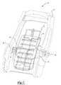
- FIGS. 1-2illustrate a seatback system in accordance with one non-limiting aspect of the present invention.
- FIG. 3illustrates a lumbar frame in accordance with one non-limiting aspect of the present invention.
- FIGS. 1-2illustrate a seatback system 10 in accordance with one non-limiting aspect of the present invention.
- the seatback system 10may be used in any number of environments to support any number of occupants.
- the seatback system 10may be used in automobiles, buses, planes, watercraft, and any number of other vehicles.
- the seatback system 10may be used in commercial, residential, and other non-vehicle seating systems and arrangements. Accordingly, the present invention is not intended to be limited to any particular application or environment.
- the system 10may include a seatback frame 12 for providing a general contour and structure of a seatback (not shown). Padding, upholstery, and other features may be attached or otherwise connected to the seatback frame 12 to facilitate supporting and comforting a seat occupant, as one having ordinary skill in the art will appreciate.
- the system 10may include a lumbar support 14 to support a lumbar portion of the seat occupant.
- the lumbar support 14may be generally elongated and comprise a rigid or semi-rigid material having properties for supporting the lumbar portion of the seat occupant.
- the lumbar support 14is configured to flex in/out to support the seat occupant. Any number of suitable plastics and metals, or combinations thereof, having sufficient flexibility may be used. Optionally, openings or other apertures may be include to facilitate the flexing thereof.
- the lumbar support 14may be connected to or otherwise attached to a lumbar frame 16 .
- the lumbar frame 16may include a pair of rails to which the lumbar support 14 may connect.
- the frame 16may permit vertical (up/down) motion of the lumbar support 14 , such as to permit the lumbar support to be positioned relative to the lumbar portion of the occupant.
- One or more actuators 18 - 20may be attached to the lumbar frame to control movement of the lumbar support within the frame.
- the actuators 18 - 20may be mechanically and/or electrically driven.
- a mechanical or electrical device(not shown) may be included on the lumbar frame 14 or in other communication with the actuator to control the operation thereof.
- the device(not show) may be a switch or lever connected to the seatback frame 12 or to another feature in the vicinity of the system 10 to facilitate controlling the actuators 18 - 20 .
- a control module(not shown) or other feature may be configured to receive signals from the switch for electrically actuating the actuators 18 - 20 , and thereby, control positioning of the lumbar support and/or the seatback frame.
- the actuatormay be connect to the lumbar support through cables 22 - 26 or other features. Axial ends of the lumbar support 14 may include hooking features 30 - 34 to connect the lumbar support 14 to the cables 22 - 26 to permit the movement thereof.
- the actuators 18 - 20may be rotary actuators configured to wind and unwind the cables 22 - 26 so as to move the lumbar support in an up/down manner, such as to provide two-way movement of the lumbar support.
- the actuators 18 - 20may be configured to permit one end of the lumbar support 14 to move while the other end remains fixed such that the lumbar support 14 is caused to flex in/out.
- the flexing of the lumbar support 14 in this mannermay be used to control bulging or bowing of the lumbar support 14 , and thereby, the amount of lumbar support provided against the lumbar portion of the seat occupant.
- Pivots 38 - 40may be connected to the lumbar frame 14 by way of brackets 42 - 44 and/or other features. The pivots 38 - 40 may then be used to permit rotation of the lumbar frame 16 , and all features connected thereto, about the seatback frame 12 .
- the pivots 38 - 40may be a free-floating feature configured to rotate in response to pressure applied to the lumbar support 14 by the seat occupant.
- the pivots 38 - 40may include bearings or other features (not shown) to facilitate the rotation thereof.
- the connecting of the lumbar support 14 to the lumbar frame 16 and the lumber frame 16 to the pivots 38 - 40cause both of the lumbar support 14 and frame 16 to rotate with the applied pressure.
- the actuators 18 - 20 connected to the lumbar frame 16are similarly rotated to cause all lumbar features to rotate with the applied pressure.
- the rotation of the lumbar support 14 and attendant featuresmay be advantageous in improving alignment of the lumbar support 14 relative to the seat occupant.
- the rotating lumbar support 14may provide a self-adjusting lumbar feature to improve alignment of the lumbar support relative to the seat occupant, such as to permit an apex of the lumbar support to mold or confirm to spinal contours of the seat occupant.
- the pivots 38 - 40connect to the lumbar frame 16 , which in turn connects to the lumbar support 14 and actuators 18 - 20 .
- the present inventionis not so limited and fully contemplates any number of variations to this arrangement.
- the pivots 38 - 40are intended to rotate the lumbar support 14 and features attendant to the operation thereof so that the lumbar support 14 self-adjusts to the seat occupant. Accordingly, the pivots 38 - 40 may be connected to anyone of the features associated with the lumbar support 14 , and/or the lumbar support 14 itself, as long as the lumbar support 14 is able to self-adjust to the seat occupant.
- FIG. 3illustrates the lumbar frame 16 in accordance with one non-limiting aspect of the present invention.
- the lumbar frame 16may include angled, outboard features 48 - 50 at the axial ends thereof.
- the outboard features 48 - 50may extend out board of the lumbar support 14 towards the seat occupant such that pressure may be applied thereto by the seat occupant.
- the outboard portions 48 - 50may be used to facilitate rotation of the lumbar support 14 as the outboard portions 48 - 50 tend to enhance rotation of the lumbar support 14 so that less pressure is required by the seat occupant to self-adjust the positioning thereof.
- a pivot actuator(not shown) may be used in place of the free-floating pivots 38 - 40 to provide controlled motion of the lumbar support 14 and attendant features.
- the pivot actuatormay be electronically controlled by the seat occupant and/or with signals generated from the control module.
- sensorsmay be positioned at the ends of the lumbar frame 16 to sense pressure and permit the self-adjustment of the lumbar support 14 . The pressure signals may then be used by the control module to control pivoting of the pivot lumbar, and thereby, positioning of the lumbar support.
Landscapes
- Engineering & Computer Science (AREA)
- Mechanical Engineering (AREA)
- Seats For Vehicles (AREA)
Abstract
Description
Claims (20)
Priority Applications (1)
| Application Number | Priority Date | Filing Date | Title |
|---|---|---|---|
| US11/164,296US7393054B2 (en) | 2005-11-17 | 2005-11-17 | Self adjusting seatback system |
Applications Claiming Priority (1)
| Application Number | Priority Date | Filing Date | Title |
|---|---|---|---|
| US11/164,296US7393054B2 (en) | 2005-11-17 | 2005-11-17 | Self adjusting seatback system |
Publications (2)
| Publication Number | Publication Date |
|---|---|
| US20070108816A1 US20070108816A1 (en) | 2007-05-17 |
| US7393054B2true US7393054B2 (en) | 2008-07-01 |
Family
ID=38040024
Family Applications (1)
| Application Number | Title | Priority Date | Filing Date |
|---|---|---|---|
| US11/164,296Expired - Fee RelatedUS7393054B2 (en) | 2005-11-17 | 2005-11-17 | Self adjusting seatback system |
Country Status (1)
| Country | Link |
|---|---|
| US (1) | US7393054B2 (en) |
Cited By (11)
| Publication number | Priority date | Publication date | Assignee | Title |
|---|---|---|---|---|
| US20080164738A1 (en)* | 2006-12-11 | 2008-07-10 | Schukra Of North America, Ltd. | Lumbar system for climate seating |
| US7878590B1 (en)* | 2006-12-22 | 2011-02-01 | B&B Innovators, Llc | Vertebral column support for mesh back chairs |
| CN102079260A (en)* | 2009-11-30 | 2011-06-01 | 现代自动车株式会社 | Lumbar supporting device for vehicle |
| US20130001993A1 (en)* | 2010-03-24 | 2013-01-03 | Fumihiro Kurata | Lumbar support device for chair |
| US8944977B2 (en) | 2006-04-12 | 2015-02-03 | Daniel N. Foster | Combination ergonomic task chair and exercise device |
| US9004597B2 (en) | 2012-09-20 | 2015-04-14 | Steelcase Inc. | Chair back mechanism and control assembly |
| US9827503B2 (en) | 2015-04-17 | 2017-11-28 | Lagoon Corporation, Inc. | Restraint system for amusement ride |
| US9950647B2 (en) | 2015-04-17 | 2018-04-24 | Lagoon Corporation, Inc. | Seat form for amusement rides |
| US10023075B2 (en) | 2016-06-17 | 2018-07-17 | Toyota Motor Engineering & Manufacturing North America, Inc | Automatically adjusting vehicle seat back supports of vehicle seat assemblies |
| US20180251004A1 (en)* | 2017-03-03 | 2018-09-06 | Toyota Boshoku Kabushiki Kaisha | Vehicle seat |
| US11304528B2 (en) | 2012-09-20 | 2022-04-19 | Steelcase Inc. | Chair assembly with upholstery covering |
Families Citing this family (10)
| Publication number | Priority date | Publication date | Assignee | Title |
|---|---|---|---|---|
| DE102005036774B4 (en)* | 2005-08-04 | 2011-03-31 | Schukra Gerätebau AG | lumbar support |
| US7841663B2 (en)* | 2008-10-01 | 2010-11-30 | Lear Corporation | Vehicle seat lumbar system |
| KR101717172B1 (en)* | 2011-03-28 | 2017-03-16 | 엘 앤드 피 스위스 홀딩 아게 | Actuator arrangement for a seat and adjusting method |
| DE102012013208B4 (en)* | 2012-05-07 | 2019-07-25 | Adient Luxembourg Holding S.À R.L. | Seat part of a vehicle seat |
| CN104284799B (en) | 2012-05-07 | 2017-03-22 | 约翰逊控制技术公司 | Seat adjustment device for vertical adjustment of vehicle seat |
| KR101545928B1 (en)* | 2015-04-03 | 2015-08-20 | (주)디에스시 | Lumbar Support Assembly |
| US9796308B2 (en)* | 2015-05-05 | 2017-10-24 | Ami Industries, Inc. | Flexible lumbar support of aircraft seat |
| US10952535B2 (en)* | 2018-11-05 | 2021-03-23 | La-Z-Boy Incorporated | Furniture member having lumbar adjustment mechanism |
| US11672348B2 (en) | 2018-11-05 | 2023-06-13 | La-Z-Boy Incorporated | Furniture member having lumbar adjustment mechanism |
| US11324324B2 (en) | 2018-11-05 | 2022-05-10 | La-Z-Boy Incorporated | Furniture member having lumbar adjustment mechanism |
Citations (36)
| Publication number | Priority date | Publication date | Assignee | Title |
|---|---|---|---|---|
| US272579A (en)* | 1883-02-20 | William h | ||
| US1789821A (en)* | 1927-11-10 | 1931-01-20 | William H Leffingwell | Chair |
| US2831533A (en)* | 1955-12-14 | 1958-04-22 | Pasquarelli Blase | Back support for automobiles-back saver |
| US2843195A (en)* | 1956-01-25 | 1958-07-15 | Alvar E A Barvaeus | Self-adjusting back support |
| US2991124A (en)* | 1958-09-26 | 1961-07-04 | Schwarz Johann | Back supporting attachment for seat backs |
| US3121592A (en)* | 1962-08-29 | 1964-02-18 | Gen Fireproofing Co | Posture chair |
| US4469374A (en) | 1981-11-20 | 1984-09-04 | Namba Press Works Co., Ltd. | Automotive seat |
| US4556251A (en) | 1983-10-18 | 1985-12-03 | Tachikawa Spring Co., Ltd. | Lumbar support device |
| US4623193A (en) | 1983-02-28 | 1986-11-18 | P.A. Rentrop Hubert & Wagner Fahrzeugausstattungen GmbH & Co KG | Seat with lumbar support |
| US4711493A (en) | 1985-04-17 | 1987-12-08 | General Motors Corporation | Mounting or locking assembly, especially for use with pivotable motor vehicle seats |
| US4832401A (en) | 1988-04-01 | 1989-05-23 | General Motors Corporation | Apparatus and method of a seat with a floating lumbar |
| US4880271A (en) | 1987-12-28 | 1989-11-14 | Wickes Manufacturing Company | Adjustable lumbar support |
| US5110121A (en) | 1990-09-28 | 1992-05-05 | Foster Daniel N | Exercise chair for the lower back |
| US5113176A (en) | 1990-11-13 | 1992-05-12 | Staodyn, Inc. | Lumbar roll with audible alerting capability |
| US5244252A (en) | 1990-10-29 | 1993-09-14 | Hector Serber | Seat assembly and method |
| US5425566A (en)* | 1990-09-05 | 1995-06-20 | Buchacz; Jurek | Working chair |
| US5505520A (en) | 1994-11-03 | 1996-04-09 | Ford Motor Company | Passenger seat with adjustable lumbar support |
| US5730688A (en) | 1996-03-28 | 1998-03-24 | Prusick; Vincent R. | Portable abdominal-lumbar exercise device |
| US5735574A (en)* | 1994-09-13 | 1998-04-07 | Serber; Hector | Seat lumbar motion chair, assembly and method |
| US5772281A (en) | 1997-05-19 | 1998-06-30 | Lear Corporation | Dual spring back suspension system for an automotive seat |
| US6309018B1 (en) | 1996-09-09 | 2001-10-30 | Volvo Car Corporation | Back support structure for a seat |
| US6312366B1 (en) | 1996-03-28 | 2001-11-06 | Vipa, L.L.C. | Exercising device |
| US20010043002A1 (en) | 2000-03-30 | 2001-11-22 | Hidetoshi Nakane | Lumbar support device |
| US20020008417A1 (en) | 2000-06-28 | 2002-01-24 | Bert Holst | Vehicle seat lumbar support system |
| US20030012240A1 (en) | 1998-12-07 | 2003-01-16 | Tsuyoshi Yamamoto | Semiconductor laser and method of manufacturing the same |
| US20030057757A1 (en) | 2001-09-26 | 2003-03-27 | Martin Charles N. | Therapeutic chair |
| US20030197393A1 (en) | 2002-04-22 | 2003-10-23 | Hanagan Michael W. | Vehicle seat with movable backrest |
| US20040061362A1 (en) | 2002-09-30 | 2004-04-01 | Mark Farquhar | Vehicle seat having active head restraint system |
| US6719368B1 (en) | 2001-02-28 | 2004-04-13 | Magna Seating Systems Inc. | Vehicle seat assembly having a cradle seat back |
| US6749261B2 (en)* | 1997-10-24 | 2004-06-15 | Steelcase Development Corporation | Seating unit including novel back construction |
| US6837541B2 (en) | 2002-09-30 | 2005-01-04 | Lear Corporation | Vehicle seat having a lumbar support system |
| US20050046252A1 (en) | 2003-09-03 | 2005-03-03 | Mcmillen Robert J. | Occupant centering ergonomic support apparatus and method |
| US20050147515A1 (en) | 2003-12-30 | 2005-07-07 | Cusak Stanley M. | Chair providing dynamic thrust to exercise lumbar area of spine |
| US20050161980A1 (en) | 2003-09-03 | 2005-07-28 | Mostafa Rashidy | Structural seat system for an automotive vehicle |
| US6938956B1 (en)* | 2002-09-06 | 2005-09-06 | Pro-Cord Spa | Chair backrest |
| US7000987B2 (en)* | 2000-02-17 | 2006-02-21 | Richard Van Seenus Nederland B.V. | Device for supporting a seated person and method for adjusting, designing and/or manufacturing such a device |
- 2005
- 2005-11-17USUS11/164,296patent/US7393054B2/ennot_activeExpired - Fee Related
Patent Citations (39)
| Publication number | Priority date | Publication date | Assignee | Title |
|---|---|---|---|---|
| US272579A (en)* | 1883-02-20 | William h | ||
| US1789821A (en)* | 1927-11-10 | 1931-01-20 | William H Leffingwell | Chair |
| US2831533A (en)* | 1955-12-14 | 1958-04-22 | Pasquarelli Blase | Back support for automobiles-back saver |
| US2843195A (en)* | 1956-01-25 | 1958-07-15 | Alvar E A Barvaeus | Self-adjusting back support |
| US2991124A (en)* | 1958-09-26 | 1961-07-04 | Schwarz Johann | Back supporting attachment for seat backs |
| US3121592A (en)* | 1962-08-29 | 1964-02-18 | Gen Fireproofing Co | Posture chair |
| US4469374A (en) | 1981-11-20 | 1984-09-04 | Namba Press Works Co., Ltd. | Automotive seat |
| US4623193A (en) | 1983-02-28 | 1986-11-18 | P.A. Rentrop Hubert & Wagner Fahrzeugausstattungen GmbH & Co KG | Seat with lumbar support |
| US4556251A (en) | 1983-10-18 | 1985-12-03 | Tachikawa Spring Co., Ltd. | Lumbar support device |
| US4711493A (en) | 1985-04-17 | 1987-12-08 | General Motors Corporation | Mounting or locking assembly, especially for use with pivotable motor vehicle seats |
| US4880271A (en) | 1987-12-28 | 1989-11-14 | Wickes Manufacturing Company | Adjustable lumbar support |
| US4832401A (en) | 1988-04-01 | 1989-05-23 | General Motors Corporation | Apparatus and method of a seat with a floating lumbar |
| US5425566A (en)* | 1990-09-05 | 1995-06-20 | Buchacz; Jurek | Working chair |
| US5110121A (en) | 1990-09-28 | 1992-05-05 | Foster Daniel N | Exercise chair for the lower back |
| US5244252A (en) | 1990-10-29 | 1993-09-14 | Hector Serber | Seat assembly and method |
| US5113176A (en) | 1990-11-13 | 1992-05-12 | Staodyn, Inc. | Lumbar roll with audible alerting capability |
| US5735574A (en)* | 1994-09-13 | 1998-04-07 | Serber; Hector | Seat lumbar motion chair, assembly and method |
| US5505520A (en) | 1994-11-03 | 1996-04-09 | Ford Motor Company | Passenger seat with adjustable lumbar support |
| US6312366B1 (en) | 1996-03-28 | 2001-11-06 | Vipa, L.L.C. | Exercising device |
| US5730688A (en) | 1996-03-28 | 1998-03-24 | Prusick; Vincent R. | Portable abdominal-lumbar exercise device |
| US6309018B1 (en) | 1996-09-09 | 2001-10-30 | Volvo Car Corporation | Back support structure for a seat |
| US5772281A (en) | 1997-05-19 | 1998-06-30 | Lear Corporation | Dual spring back suspension system for an automotive seat |
| US6749261B2 (en)* | 1997-10-24 | 2004-06-15 | Steelcase Development Corporation | Seating unit including novel back construction |
| US20030012240A1 (en) | 1998-12-07 | 2003-01-16 | Tsuyoshi Yamamoto | Semiconductor laser and method of manufacturing the same |
| US7000987B2 (en)* | 2000-02-17 | 2006-02-21 | Richard Van Seenus Nederland B.V. | Device for supporting a seated person and method for adjusting, designing and/or manufacturing such a device |
| US20010043002A1 (en) | 2000-03-30 | 2001-11-22 | Hidetoshi Nakane | Lumbar support device |
| US6499803B2 (en) | 2000-03-30 | 2002-12-31 | Aisin Seiki Kabushiki Kaisha | Lumbar support device |
| US6644740B2 (en) | 2000-06-28 | 2003-11-11 | Lear Corporation | Vehicle seat lumbar support system |
| US20020008417A1 (en) | 2000-06-28 | 2002-01-24 | Bert Holst | Vehicle seat lumbar support system |
| US6719368B1 (en) | 2001-02-28 | 2004-04-13 | Magna Seating Systems Inc. | Vehicle seat assembly having a cradle seat back |
| US20040075312A1 (en) | 2001-02-28 | 2004-04-22 | Neale Colin G. | Vehicle seat assembly having a cradle seat back |
| US20030057757A1 (en) | 2001-09-26 | 2003-03-27 | Martin Charles N. | Therapeutic chair |
| US20030197393A1 (en) | 2002-04-22 | 2003-10-23 | Hanagan Michael W. | Vehicle seat with movable backrest |
| US6938956B1 (en)* | 2002-09-06 | 2005-09-06 | Pro-Cord Spa | Chair backrest |
| US20040061362A1 (en) | 2002-09-30 | 2004-04-01 | Mark Farquhar | Vehicle seat having active head restraint system |
| US6837541B2 (en) | 2002-09-30 | 2005-01-04 | Lear Corporation | Vehicle seat having a lumbar support system |
| US20050161980A1 (en) | 2003-09-03 | 2005-07-28 | Mostafa Rashidy | Structural seat system for an automotive vehicle |
| US20050046252A1 (en) | 2003-09-03 | 2005-03-03 | Mcmillen Robert J. | Occupant centering ergonomic support apparatus and method |
| US20050147515A1 (en) | 2003-12-30 | 2005-07-07 | Cusak Stanley M. | Chair providing dynamic thrust to exercise lumbar area of spine |
Cited By (31)
| Publication number | Priority date | Publication date | Assignee | Title |
|---|---|---|---|---|
| US8944977B2 (en) | 2006-04-12 | 2015-02-03 | Daniel N. Foster | Combination ergonomic task chair and exercise device |
| US20080164738A1 (en)* | 2006-12-11 | 2008-07-10 | Schukra Of North America, Ltd. | Lumbar system for climate seating |
| US7614696B2 (en)* | 2006-12-11 | 2009-11-10 | Schukra Of North America | Lumbar system for climate seating |
| US7878590B1 (en)* | 2006-12-22 | 2011-02-01 | B&B Innovators, Llc | Vertebral column support for mesh back chairs |
| CN102079260A (en)* | 2009-11-30 | 2011-06-01 | 现代自动车株式会社 | Lumbar supporting device for vehicle |
| CN102079260B (en)* | 2009-11-30 | 2014-12-17 | 现代自动车株式会社 | Lumbar supporting device for vehicle |
| US20130001993A1 (en)* | 2010-03-24 | 2013-01-03 | Fumihiro Kurata | Lumbar support device for chair |
| US8845025B2 (en)* | 2010-03-24 | 2014-09-30 | Takano Co., Ltd. | Lumbar support device for chair |
| US9049935B2 (en) | 2012-09-20 | 2015-06-09 | Steelcase Inc. | Control assembly for chair |
| US9492013B2 (en) | 2012-09-20 | 2016-11-15 | Steelcase Inc. | Chair back mechanism and control assembly |
| US9022476B2 (en) | 2012-09-20 | 2015-05-05 | Steelcase Inc. | Control assembly for chair |
| US9027997B2 (en) | 2012-09-20 | 2015-05-12 | Steelcasel Inc. | Chair assembly |
| US9027999B2 (en) | 2012-09-20 | 2015-05-12 | Steelcase Inc. | Control assembly for chair |
| US9027998B2 (en) | 2012-09-20 | 2015-05-12 | Steelcase Inc. | Chair assembly |
| US9004597B2 (en) | 2012-09-20 | 2015-04-14 | Steelcase Inc. | Chair back mechanism and control assembly |
| USD742677S1 (en) | 2012-09-20 | 2015-11-10 | Steelcase Inc. | Chair |
| USD742676S1 (en) | 2012-09-20 | 2015-11-10 | Steelcase Inc. | Chair |
| US9451826B2 (en) | 2012-09-20 | 2016-09-27 | Steelcase Inc. | Chair assembly |
| US9462888B2 (en) | 2012-09-20 | 2016-10-11 | Steelcase Inc. | Control assembly for chair |
| US9010859B2 (en) | 2012-09-20 | 2015-04-21 | Steelcase Inc. | Chair assembly |
| US9526339B2 (en) | 2012-09-20 | 2016-12-27 | Steelcase Inc. | Control assembly for chair |
| US11304528B2 (en) | 2012-09-20 | 2022-04-19 | Steelcase Inc. | Chair assembly with upholstery covering |
| US9844267B2 (en) | 2012-09-20 | 2017-12-19 | Steelcase Inc. | Chair back mechanism and control assembly |
| US9861201B2 (en) | 2012-09-20 | 2018-01-09 | Steelcase, Inc. | Chair assembly |
| US9918552B2 (en) | 2012-09-20 | 2018-03-20 | Steelcase Inc. | Control assembly for chair |
| US10206507B2 (en) | 2012-09-20 | 2019-02-19 | Steelcase Inc. | Control assembly for chair |
| US9950647B2 (en) | 2015-04-17 | 2018-04-24 | Lagoon Corporation, Inc. | Seat form for amusement rides |
| US9827503B2 (en) | 2015-04-17 | 2017-11-28 | Lagoon Corporation, Inc. | Restraint system for amusement ride |
| US10023075B2 (en) | 2016-06-17 | 2018-07-17 | Toyota Motor Engineering & Manufacturing North America, Inc | Automatically adjusting vehicle seat back supports of vehicle seat assemblies |
| US20180251004A1 (en)* | 2017-03-03 | 2018-09-06 | Toyota Boshoku Kabushiki Kaisha | Vehicle seat |
| US10625565B2 (en)* | 2017-03-03 | 2020-04-21 | Toyota Boshoku Kabushiki Kaisha | Vehicle seat |
Also Published As
| Publication number | Publication date |
|---|---|
| US20070108816A1 (en) | 2007-05-17 |
Similar Documents
| Publication | Publication Date | Title |
|---|---|---|
| US7393054B2 (en) | Self adjusting seatback system | |
| US9821694B2 (en) | Seat with pneumatic headrest and thigh adjustment | |
| CN106965727B (en) | Personified pivotable upper seat back support | |
| US8851574B2 (en) | Folding vehicle head restraint assembly | |
| US8348347B2 (en) | Folding vehicle head restraint assembly | |
| KR101394940B1 (en) | Pivot pin retainer mechanism | |
| US6905170B2 (en) | Fold down seat lumbar support apparatus and method | |
| US9987950B2 (en) | Vehicle seat electrical connector bracket assembly | |
| US9315130B2 (en) | Articulating head restraint | |
| US7658447B2 (en) | Vehicle seat with auto-fold leg | |
| WO2007026790A1 (en) | Vehicle seat and method of assembling vehicle seat | |
| US20110012413A1 (en) | Reclining seat assembly | |
| US20040140705A1 (en) | Automatically actuating ergonomic support system for a fold down seat | |
| WO2006046719A1 (en) | Cushion plate with pressure regulating mechanism of vehicle seat | |
| US11292370B2 (en) | Rear seat for vehicle | |
| US20170028875A1 (en) | Vehicle seat | |
| CN104512287A (en) | Conveyance seat | |
| KR20150005657A (en) | Seat inclination adjustment mechanism, vehicle seat, and method for mounting said vehicle seat | |
| US10406948B2 (en) | Vehicle seat | |
| CN113492736A (en) | Relaxing comfortable seat for vehicle | |
| US11479156B2 (en) | Lumbar support device | |
| US20060220433A1 (en) | Vision improving system for a head restraint | |
| US5738475A (en) | Adjustable expansion rivet | |
| CN105365610A (en) | Reclining apparatus for rear seat in a car | |
| JPH0811603A (en) | Power comfort seat structure |
Legal Events
| Date | Code | Title | Description |
|---|---|---|---|
| AS | Assignment | Owner name:LEAR CORPORATION, MICHIGAN Free format text:ASSIGNMENT OF ASSIGNORS INTEREST;ASSIGNORS:MCQUEEN, KENNETH;BACARELLA, PETER A.;WAWRZYNIAK, JIM;REEL/FRAME:016794/0296 Effective date:20051114 Owner name:LEAR CORPORATION,MICHIGAN Free format text:ASSIGNMENT OF ASSIGNORS INTEREST;ASSIGNORS:MCQUEEN, KENNETH;BACARELLA, PETER A.;WAWRZYNIAK, JIM;REEL/FRAME:016794/0296 Effective date:20051114 | |
| AS | Assignment | Owner name:JPMORGAN CHASE BANK, N.A., AS ADMINISTRATIVE AGENT Free format text:GRANT OF FIRST LIEN SECURITY INTEREST IN PATENT RIGHTS;ASSIGNOR:LEAR CORPORATION;REEL/FRAME:023519/0267 Effective date:20091109 Owner name:JPMORGAN CHASE BANK, N.A., AS ADMINISTRATIVE AGENT Free format text:GRANT OF SECOND LIEN SECURITY INTEREST IN PATENT RIGHTS;ASSIGNOR:LEAR CORPORATION;REEL/FRAME:023519/0626 Effective date:20091109 | |
| FPAY | Fee payment | Year of fee payment:4 | |
| AS | Assignment | Owner name:JPMORGAN CAHSE BANK, N.A., AS AGENT, ILLINOIS Free format text:SECURITY INTEREST;ASSIGNOR:LEAR CORPORATION;REEL/FRAME:030076/0016 Effective date:20130130 Owner name:JPMORGAN CHASE BANK, N.A., AS AGENT, ILLINOIS Free format text:SECURITY INTEREST;ASSIGNOR:LEAR CORPORATION;REEL/FRAME:030076/0016 Effective date:20130130 | |
| AS | Assignment | Owner name:LEAR CORPORATION, MICHIGAN Free format text:RELEASE BY SECURED PARTY;ASSIGNOR:JPMORGAN CHASE BANK, N.A.;REEL/FRAME:032770/0843 Effective date:20100830 | |
| AS | Assignment | Owner name:LEAR CORPORATION, MICHIGAN Free format text:RELEASE BY SECURED PARTY;ASSIGNOR:JPMORGAN CHASE BANK, N.A., AS AGENT;REEL/FRAME:037701/0251 Effective date:20160104 Owner name:LEAR CORPORATION, MICHIGAN Free format text:RELEASE BY SECURED PARTY;ASSIGNOR:JPMORGAN CHASE BANK, N.A., AS AGENT;REEL/FRAME:037701/0340 Effective date:20160104 Owner name:LEAR CORPORATION, MICHIGAN Free format text:RELEASE BY SECURED PARTY;ASSIGNOR:JPMORGAN CHASE BANK, N.A., AS AGENT;REEL/FRAME:037701/0180 Effective date:20160104 | |
| AS | Assignment | Owner name:LEAR CORPORATION, MICHIGAN Free format text:RELEASE BY SECURED PARTY;ASSIGNOR:JPMORGAN CHASE BANK, N.A., AS AGENT;REEL/FRAME:037702/0911 Effective date:20160104 | |
| REMI | Maintenance fee reminder mailed | ||
| LAPS | Lapse for failure to pay maintenance fees | ||
| STCH | Information on status: patent discontinuation | Free format text:PATENT EXPIRED DUE TO NONPAYMENT OF MAINTENANCE FEES UNDER 37 CFR 1.362 | |
| FP | Lapsed due to failure to pay maintenance fee | Effective date:20160701 |