US7392955B1 - System and method for temperature control of hot-water supply system - Google Patents
System and method for temperature control of hot-water supply systemDownload PDFInfo
- Publication number
- US7392955B1 US7392955B1US11/098,003US9800305AUS7392955B1US 7392955 B1US7392955 B1US 7392955B1US 9800305 AUS9800305 AUS 9800305AUS 7392955 B1US7392955 B1US 7392955B1
- Authority
- US
- United States
- Prior art keywords
- water
- hot water
- cold water
- central channel
- water side
- Prior art date
- Legal status (The legal status is an assumption and is not a legal conclusion. Google has not performed a legal analysis and makes no representation as to the accuracy of the status listed.)
- Active, expires
Links
- XLYOFNOQVPJJNP-UHFFFAOYSA-NwaterSubstancesOXLYOFNOQVPJJNP-UHFFFAOYSA-N0.000titleclaimsabstractdescription239
- 239000012530fluidSubstances0.000claimsabstractdescription17
- 238000012986modificationMethods0.000description2
- 230000004048modificationEffects0.000description2
- 239000002699waste materialSubstances0.000description2
- 230000000903blocking effectEffects0.000description1
- 239000000356contaminantSubstances0.000description1
- 238000001816coolingMethods0.000description1
Images


Classifications
- E—FIXED CONSTRUCTIONS
- E03—WATER SUPPLY; SEWERAGE
- E03B—INSTALLATIONS OR METHODS FOR OBTAINING, COLLECTING, OR DISTRIBUTING WATER
- E03B7/00—Water main or service pipe systems
- E03B7/04—Domestic or like local pipe systems
- E03B7/045—Domestic or like local pipe systems diverting initially cold water in warm water supply
- G—PHYSICS
- G05—CONTROLLING; REGULATING
- G05D—SYSTEMS FOR CONTROLLING OR REGULATING NON-ELECTRIC VARIABLES
- G05D23/00—Control of temperature
- G05D23/01—Control of temperature without auxiliary power
- G05D23/12—Control of temperature without auxiliary power with sensing element responsive to pressure or volume changes in a confined fluid
- E—FIXED CONSTRUCTIONS
- E03—WATER SUPPLY; SEWERAGE
- E03C—DOMESTIC PLUMBING INSTALLATIONS FOR FRESH WATER OR WASTE WATER; SINKS
- E03C1/00—Domestic plumbing installations for fresh water or waste water; Sinks
- E03C1/02—Plumbing installations for fresh water
- E03C1/04—Water-basin installations specially adapted to wash-basins or baths
- E03C1/044—Water-basin installations specially adapted to wash-basins or baths having a heating or cooling apparatus in the supply line
- F—MECHANICAL ENGINEERING; LIGHTING; HEATING; WEAPONS; BLASTING
- F16—ENGINEERING ELEMENTS AND UNITS; GENERAL MEASURES FOR PRODUCING AND MAINTAINING EFFECTIVE FUNCTIONING OF MACHINES OR INSTALLATIONS; THERMAL INSULATION IN GENERAL
- F16K—VALVES; TAPS; COCKS; ACTUATING-FLOATS; DEVICES FOR VENTING OR AERATING
- F16K31/00—Actuating devices; Operating means; Releasing devices
- F16K31/002—Actuating devices; Operating means; Releasing devices actuated by temperature variation
- G—PHYSICS
- G05—CONTROLLING; REGULATING
- G05D—SYSTEMS FOR CONTROLLING OR REGULATING NON-ELECTRIC VARIABLES
- G05D23/00—Control of temperature
- G05D23/01—Control of temperature without auxiliary power
- G05D23/12—Control of temperature without auxiliary power with sensing element responsive to pressure or volume changes in a confined fluid
- G05D23/123—Control of temperature without auxiliary power with sensing element responsive to pressure or volume changes in a confined fluid the sensing element being placed within a regulating fluid flow
Definitions
- the present inventionrelates generally to the field of water supply systems.
- the inventionrelates to the control of temperature of a hot-water supply system.
- wateris made available at one or more outlets, such as sinks, tubs, showers or appliances, through a cold water line and a hot water line.
- waterenters the supply system from a source, such as a well or a water main, and is directed, on the one side, to a cold water line and, on the other side, to a water heater. Hot water from the water heater is then directed to a hot water line. The hot and cold water lines are then mixed at the outlet to provide water at a desired temperature.
- hot watermay not be immediately available at all outlets at all times.
- water in the line between the water heater and an outletmay cool to room temperature overnight. Hot water does not become available at an outlet until the cooled water in the line is first drawn and wasted. This problem may be particularly apparent at an outlet that is furthest from the water heater. At such an outlet, the amount of cooled water that must be drawn before hot water becomes available may be quite large.
- U.S. Pat. No. 6,536,464which is hereby incorporated by reference, proposes a thermostatically controlled bypass valve positioned within a tubular body between the hot water side and the cold water side.
- the valveopens a passage between the hot water side and the cold water side when the hot water is too cool.
- the bypass valveis positioned well within the tubular body and cannot be accessed for adjustment of the temperature at which the valve should close.
- the valve assemblyincludes a hot water side with a hot water inlet and a cold water side.
- the valve assemblyalso includes a central channel for fluid communication between the cold water side and the hot water side and a bypass valve portion.
- the bypass valve portionincludes a thermostatic valve adapted to substantially block the fluid communication through the central channel between the cold water side and the hot water side when a temperature of water flowing through the central channel increases above a threshold temperature.
- the bypass valve portionalso includes a mechanical temperature adjustment portion adapted to selectively vary the threshold temperature.
- FIG. 1is a schematic illustration of an embodiment of a water-supply system according to the present invention
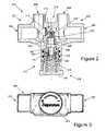
- FIG. 2is a cross-sectional illustration of a valve assembly according to an embodiment of the invention.
- FIG. 3is a front plan view of the valve assembly of FIG. 2 ;
- FIG. 4illustrates a perspective view of a circulating pump adapter for use with the water-supply system of FIG. 1 ;
- FIG. 5is a top plan view of the circulating pump adapter of FIG. 4 ;
- FIG. 6is a cross-sectional illustration of the circulating pump adapter of FIGS. 4 and 5 .
- the water supply system 10may be installed in any house, building or other structure for providing water to one or more outlets, such as water outlet 24 .
- the water outlet 24may be a sink, a tub, a shower or the like.
- the water supply system 10is illustrated with a single water outlet 24 , it will be understood by those skilled in the art that additional water outlets may be positioned at various points of the water supply system 10 .
- the water supply system 10receives water from a supply line 12 which directs water into the water supply system 10 from a source such as a well or a local water reservoir, for example.
- the water in the supply line 12is then directed to a first branch 14 and a second branch 16 .
- Water in the first branch 14is directed to a hot water system through a water heater 22 , which heats the water to a desired temperature.
- the temperature of the hot watermay be set using a dial or other control on the water heater 22 .
- the heated watercan then be drawn by the water outlet 24 through a hot water supply line 18 connecting the water heater 22 and the water outlet 24 .
- a circulating pump assembly 300is positioned on the first branch 14 between the supply line 12 and the water heater 22 . The circulating pump assembly 300 is described in greater detail below with reference to FIGS. 4-6 .
- Cold wateris supplied to the water outlet 24 through a cold water supply line 20 connected to the second branch 16 , where it can be mixed with hot water from the hot water supply line 18 .
- the hot water supply line 18 and the cold water supply line 20lead to a bypass valve assembly 200 positioned at the water outlet 24 .
- a hot water connector 26 and a cold water connector 28provide hot water and cold water, respectively, from the bypass valve assembly 200 to the water outlet 24 , which may include controls, such as knobs, to control the amount and temperature of water drawn.
- the bypass valve assembly 200includes a hot water side 201 and a cold water side 205 .
- the hot water side 201includes a hot water inlet 202 and a hot water outlet 204 .
- the hot water inlet 202is adapted to receive water from the water heater 22 through the hot water supply line 18 ( FIG. 1 ).
- the hot water outlet 204directs water to a water outlet, such as water outlet 24 shown in FIG. 1 .
- the cold water side 205 of the illustrated embodiment of the bypass valve assembly 200includes a cold water inlet 206 and a cold water outlet 208 .
- the cold water inlet 206is adapted to receive water from the cold water supply line 20 , and the cold water outlet 208 directs water to the water outlet 24 ( FIG. 1 ).
- the hot water side 201 and the cold water side 205are separated by a central portion 210 of the bypass valve assembly 200 .
- a central channel 214 , 216is provided through the central portion 210 for fluid communication between the hot water side 201 and the cold water side 205 .
- a bypass valve portion 212is positioned substantially perpendicular to an axis formed by the hot water inlet 202 and the cold water inlet 206 and aligned with the central portion 210 .
- a thermostatic valve 222is positioned within the bypass valve portion 212 .
- the thermostatic valve 222has a thermally sensitive valve body 228 which is adapted to actuate a piston 224 . With increasing temperature of the thermally sensitive valve body 228 , the piston 224 is extended further.
- the thermostatic valve 222is provided with a large diameter section 226 which secures a bias spring 234 around the thermally sensitive valve body 228 .
- a bias spring 234is forced against a surface of the large diameter section 226 , while the other end is positioned around an opening of the central channel 214 , 216 in the central portion 210 .
- a piston cap 230is positioned around the piston 224 and around a portion of the thermostatic valve 222 .
- the piston cap 230includes an annular flange 232 extending outward from the thermostatic valve 222 .
- the annular flange 232provides a base for one end of an over-travel spring 236 .
- the water on the hot water sidemay cool down together with the thermally sensitive valve body 228 .
- the cooling of the thermally sensitive valve body 228causes the piston 224 to move to a retracted position.
- the bias spring 234forces the large diameter section 226 and the thermally sensitive valve body 228 away from the central channel 214 , 216 , and fluid communication between the hot water side 201 and the cold water side 205 is allowed through the central channel 214 , 216 .
- a pressure differential between the hot water side 201 and the cold water side 205 created by the circulation pump assembly 300 ( FIG. 1 )causes the cooled water to flow through the central channel 214 , 216 .
- a check valve 220is provided within the central channel 214 , 216 to prevent backward flow from the cold water side 205 to the hot water side 201 .
- a screen 218is provided at the hot water side of the central channel 214 , 216 to prevent contaminants from entering and clogging the bypass valve portion 212 .
- the screen 218may be adapted to be cleaned by the cooled water flowing therethrough.
- the temperature of the thermally sensitive valve body 228increases, causing the piston 224 to extend outward.
- the extension of the piston 224acts against the force of the bias spring 234 and causes the thermostatic valve 222 to be forced toward the central channel 214 , 216 .
- the piston 224extends sufficiently to cause the thermally sensitive valve body 228 to block the central channel 214 , 216 , thereby blocking fluid communication between the hot water side 201 and the cold water side 205 .
- wateris then directed to the hot water outlet 204 at a temperature that is at or above the threshold temperature.
- the bypass valve portion 212also includes a temperature adjustment portion 238 to allow variation of the threshold temperature at which the central channel 214 , 216 is blocked.
- the temperature adjustment portion 238is mechanical and includes a valve adjustment dial 240 with a cavity inside for accommodating the over-travel spring 236 and the piston cap 230 .
- the valve adjustment dial 240also includes an inward flange 242 which engages the annular flange 232 of the piston cap 230 and secures the piston cap 230 within the cavity.
- valve adjustment dial 240is moved inward, as may be achieved by turning the valve adjustment dial 240 clockwise, the piston cap 230 is also moved inward, resulting in a decrease in the distance between the piston cap 230 and the central channel 214 , 216 .
- the amount of extension of the piston 224 required to block the central channel 214 , 216is reduced.
- the threshold temperature at which the central channel 214 , 216 is blocked and water is directed to the hot water outlet 204is also reduced.
- valve adjustment dial 240Conversely, if the valve adjustment dial 240 is moved outward, as may be achieved by turning the valve adjustment dial 240 counterclockwise, the piston cap 230 is also moved outward, resulting in an increase in the distance between the piston cap 230 and the central channel 214 , 216 . In turn, the amount of extension of the piston 224 required to block the central channel 214 , 216 is increased. Thus, the threshold temperature at which the central channel 214 , 216 is blocked and water is directed to the hot water outlet 204 is also increased.
- a usermay be provided with an easily accessible means for adjusting the temperature at which water from the hot water side will flow from the outlet. Since the cooled water is bypassed to the cold water side, waste of water is significantly reduced or eliminated.
- a pressure differentialmay be required between the hot water side 201 and the cold water side 205 .
- a circulation pump assembly 300may be provided, as illustrated in FIG. 1 .
- FIGS. 4-6An embodiment of a circulating pump adapter 301 , which may be a part of the circulation pump assembly 300 , is illustrated in FIGS. 4-6 .
- the circulating pump adapter 301includes an inlet 302 and an outlet 304 for the cold water from the first branch 14 shown in FIG. 1 .
- the inlet 302engages the first branch 14
- the outlet 304may be connected directly to the water heater 22 , shown in FIG. 1 .
- the circulating pump adapter 301also includes a threaded pump mount 306 upon which a circulation pump (not shown) can be installed.
- the circulation pump to be installedmay be a small, low-capacity pump to provide a pressure differential sufficient to direct flow through the central channel 214 , 216 from the hot water side 201 to the cold water side 205 .
- a pressure differential of 3 psiis generated by the circulation pump.
- the circulating pump adapter 301includes a pump inlet 308 to direct water from the inlet 302 to the pump. Further, a pump outlet 310 is provided to direct water from the pump to the outlet 304 . A check valve 312 is provided to allow water to bypass the circulation pump. For example, when water is being drawn through a water outlet, such as outlet 24 of FIG. 1 , the amount of water passing through the circulation pump assembly may significantly exceed the capacity of the circulation pump. In this regard, the check valve 312 allows water to bypass the circulation pump to prevent damage to the circulation pump.
Landscapes
- Engineering & Computer Science (AREA)
- Physics & Mathematics (AREA)
- Life Sciences & Earth Sciences (AREA)
- Automation & Control Theory (AREA)
- Health & Medical Sciences (AREA)
- General Physics & Mathematics (AREA)
- Hydrology & Water Resources (AREA)
- Public Health (AREA)
- Water Supply & Treatment (AREA)
- General Engineering & Computer Science (AREA)
- Fluid Mechanics (AREA)
- Mechanical Engineering (AREA)
- Temperature-Responsive Valves (AREA)
Abstract
Description
Claims (10)
Priority Applications (1)
| Application Number | Priority Date | Filing Date | Title |
|---|---|---|---|
| US11/098,003US7392955B1 (en) | 2005-04-01 | 2005-04-01 | System and method for temperature control of hot-water supply system |
Applications Claiming Priority (1)
| Application Number | Priority Date | Filing Date | Title |
|---|---|---|---|
| US11/098,003US7392955B1 (en) | 2005-04-01 | 2005-04-01 | System and method for temperature control of hot-water supply system |
Publications (1)
| Publication Number | Publication Date |
|---|---|
| US7392955B1true US7392955B1 (en) | 2008-07-01 |
Family
ID=39561042
Family Applications (1)
| Application Number | Title | Priority Date | Filing Date |
|---|---|---|---|
| US11/098,003Active2026-04-08US7392955B1 (en) | 2005-04-01 | 2005-04-01 | System and method for temperature control of hot-water supply system |
Country Status (1)
| Country | Link |
|---|---|
| US (1) | US7392955B1 (en) |
Cited By (10)
| Publication number | Priority date | Publication date | Assignee | Title |
|---|---|---|---|---|
| US20080105305A1 (en)* | 2006-11-08 | 2008-05-08 | Ken Lum | Method and system for controlled release of hot water from a fixture |
| US20090095356A1 (en)* | 2007-10-16 | 2009-04-16 | Greenthal Steven M | Method and apparatus for conserving water |
| US20090165875A1 (en)* | 2004-12-03 | 2009-07-02 | Winns Folly Pty Ltd. | Assembly for saving water |
| US20100269908A1 (en)* | 2007-10-16 | 2010-10-28 | Greenthal Steven M | Water Conserving Devices and Processesx |
| US20130240053A1 (en)* | 2007-07-02 | 2013-09-19 | Grundfos Pumps Corporation | Water circulation system valve assemblies having water temperature control |
| US20140183220A1 (en)* | 2011-11-22 | 2014-07-03 | Saes Getters S.P.A. | Multi-beverage vending machine |
| US9732866B2 (en) | 2013-03-13 | 2017-08-15 | Scott E. Dolgos | Adjustable temperature regulated faucet |
| US20180321697A1 (en)* | 2015-11-05 | 2018-11-08 | Reliance Worldwide Corporation (Aust.) Pty. Ltd. | Thermostatic mixing valve with disinfecting facility |
| US11697929B2 (en) | 2019-01-18 | 2023-07-11 | Geberit International Ag | Anti-scald device for fluid supply system having hot water disinfection |
| US11739509B2 (en) | 2013-03-13 | 2023-08-29 | Scott E. Dolgos | Adjustable temperature regulated faucet |
Citations (10)
| Publication number | Priority date | Publication date | Assignee | Title |
|---|---|---|---|---|
| US2842155A (en) | 1956-06-14 | 1958-07-08 | Ernst A Peters | Thermostatically controlled water bypass valve |
| EP0751355A1 (en) | 1995-06-26 | 1997-01-02 | Karsten Dipl.-Ing. Laing | Transport mechanism for the cyclic transporting of the cooled down content of a pipe in a hot water distribution system |
| DE29718257U1 (en) | 1997-03-22 | 1998-07-23 | Miller, Bernhard, 70439 Stuttgart | Regulator |
| DE19712051A1 (en) | 1997-03-22 | 1998-09-24 | Miller Bernhard | Regulator for hot water supply |
| WO1998043143A1 (en) | 1997-03-22 | 1998-10-01 | Bernhard Miller | Regulator |
| US6536464B1 (en) | 2000-10-25 | 2003-03-25 | Grundfos Pumps Manufacturing Corporation | Thermostatically controlled bypass valve and water circulating system for same |
| US6929187B2 (en) | 2000-10-25 | 2005-08-16 | Grundfos Pumps Manufacturing Corporation | Water control fixture having thermostatically controlled bypass valve |
| US7073528B2 (en) | 2000-10-25 | 2006-07-11 | Grundfos Pumps Manufacturing Corp. | Water pump and thermostatically controlled bypass valve |
| US7198059B2 (en) | 2000-10-25 | 2007-04-03 | Grundfos Pumps Manufacturing Company | Apparatus and system for retrofitting water control valves |
| US20070114290A1 (en) | 2000-10-25 | 2007-05-24 | Grundfos Pumps Corporation | Water control fixture having thermostatically controlled bypass valve |
- 2005
- 2005-04-01USUS11/098,003patent/US7392955B1/enactiveActive
Patent Citations (18)
| Publication number | Priority date | Publication date | Assignee | Title |
|---|---|---|---|---|
| US2842155A (en) | 1956-06-14 | 1958-07-08 | Ernst A Peters | Thermostatically controlled water bypass valve |
| EP0751355A1 (en) | 1995-06-26 | 1997-01-02 | Karsten Dipl.-Ing. Laing | Transport mechanism for the cyclic transporting of the cooled down content of a pipe in a hot water distribution system |
| EP1018063B1 (en) | 1997-03-22 | 2004-05-26 | Bernhard Miller | Regulator |
| DE29718257U1 (en) | 1997-03-22 | 1998-07-23 | Miller, Bernhard, 70439 Stuttgart | Regulator |
| WO1998043143A1 (en) | 1997-03-22 | 1998-10-01 | Bernhard Miller | Regulator |
| AU7209298A (en) | 1997-03-22 | 1998-10-20 | Bernhard Miller | Regulator |
| DE19880372D2 (en) | 1997-03-22 | 2000-11-30 | Bernhard Miller | Regulator |
| DE19712051A1 (en) | 1997-03-22 | 1998-09-24 | Miller Bernhard | Regulator for hot water supply |
| US6929187B2 (en) | 2000-10-25 | 2005-08-16 | Grundfos Pumps Manufacturing Corporation | Water control fixture having thermostatically controlled bypass valve |
| US6536464B1 (en) | 2000-10-25 | 2003-03-25 | Grundfos Pumps Manufacturing Corporation | Thermostatically controlled bypass valve and water circulating system for same |
| US20050242199A1 (en) | 2000-10-25 | 2005-11-03 | Dale Kempf | Water control fixture having thermostatically controlled bypass valve |
| US20060049267A1 (en) | 2000-10-25 | 2006-03-09 | Ken Lum | Water control fixture having thermostatically controlled bypass valve |
| US7073528B2 (en) | 2000-10-25 | 2006-07-11 | Grundfos Pumps Manufacturing Corp. | Water pump and thermostatically controlled bypass valve |
| US7140382B2 (en) | 2000-10-25 | 2006-11-28 | Grundfos Pumps Corporation | Water circulating system having thermostatically controlled bypass valve |
| US7198059B2 (en) | 2000-10-25 | 2007-04-03 | Grundfos Pumps Manufacturing Company | Apparatus and system for retrofitting water control valves |
| US20070114290A1 (en) | 2000-10-25 | 2007-05-24 | Grundfos Pumps Corporation | Water control fixture having thermostatically controlled bypass valve |
| US20070131783A1 (en) | 2000-10-25 | 2007-06-14 | Grundfos Pumps Corporation | Water control valve assembly |
| US20070137709A1 (en) | 2000-10-25 | 2007-06-21 | Grundfos Pumps Corporation | Thermostatically controlled bypass valve |
Cited By (17)
| Publication number | Priority date | Publication date | Assignee | Title |
|---|---|---|---|---|
| US20090165875A1 (en)* | 2004-12-03 | 2009-07-02 | Winns Folly Pty Ltd. | Assembly for saving water |
| US7740182B2 (en)* | 2006-11-08 | 2010-06-22 | Grundfos Pumps Corporation | Method and system for controlled release of hot water from a fixture |
| US20080105305A1 (en)* | 2006-11-08 | 2008-05-08 | Ken Lum | Method and system for controlled release of hot water from a fixture |
| US9170584B2 (en)* | 2007-07-02 | 2015-10-27 | Grundfos Pumps Corporation | Water circulation system valve assemblies having water temperature control |
| US20130240053A1 (en)* | 2007-07-02 | 2013-09-19 | Grundfos Pumps Corporation | Water circulation system valve assemblies having water temperature control |
| US20090095356A1 (en)* | 2007-10-16 | 2009-04-16 | Greenthal Steven M | Method and apparatus for conserving water |
| US20100269908A1 (en)* | 2007-10-16 | 2010-10-28 | Greenthal Steven M | Water Conserving Devices and Processesx |
| US8245946B2 (en)* | 2007-10-16 | 2012-08-21 | Nitroworks Corporation | Method and apparatus for conserving water |
| US8740098B2 (en) | 2007-10-16 | 2014-06-03 | Nitroworks Corporation | Water conserving devices and processes |
| US20140183220A1 (en)* | 2011-11-22 | 2014-07-03 | Saes Getters S.P.A. | Multi-beverage vending machine |
| US9254060B2 (en)* | 2011-11-22 | 2016-02-09 | Saes Getters S.P.A. | Multi-beverage vending machine |
| US9732866B2 (en) | 2013-03-13 | 2017-08-15 | Scott E. Dolgos | Adjustable temperature regulated faucet |
| US10487482B2 (en) | 2013-03-13 | 2019-11-26 | Scott E. Dolgos | Adjustable temperature regulated faucet |
| US11739509B2 (en) | 2013-03-13 | 2023-08-29 | Scott E. Dolgos | Adjustable temperature regulated faucet |
| US20180321697A1 (en)* | 2015-11-05 | 2018-11-08 | Reliance Worldwide Corporation (Aust.) Pty. Ltd. | Thermostatic mixing valve with disinfecting facility |
| US10802511B2 (en)* | 2015-11-05 | 2020-10-13 | Reliance Worldwide Corporation (Aust.) Pty. Ltd. | Thermostatic mixing valve with disinfecting facility |
| US11697929B2 (en) | 2019-01-18 | 2023-07-11 | Geberit International Ag | Anti-scald device for fluid supply system having hot water disinfection |
Similar Documents
| Publication | Publication Date | Title |
|---|---|---|
| US8522814B2 (en) | Water control valve assembly | |
| US7140382B2 (en) | Water circulating system having thermostatically controlled bypass valve | |
| US7475703B2 (en) | Thermostatically controlled bypass valve | |
| US2842155A (en) | Thermostatically controlled water bypass valve | |
| US7874498B2 (en) | Water control fixture having thermostatically controlled bypass valve | |
| US7744007B2 (en) | Thermostatic mixing valves and systems | |
| US7392955B1 (en) | System and method for temperature control of hot-water supply system | |
| US4450829A (en) | Water saving system | |
| US6286464B1 (en) | Water heating system | |
| ES2227154T3 (en) | MIXING VALVE. | |
| JPH01169186A (en) | Burn preventive device for plumbing equipment | |
| US11193605B1 (en) | Hot water recirculation valve | |
| RU2508510C1 (en) | Fluid distribution control system | |
| KR101020872B1 (en) | Thermostatic valve | |
| US3096021A (en) | Hot water circulating system | |
| US20050173545A1 (en) | Faucet with internal thermostatic tempering device | |
| KR100829818B1 (en) | Hot water supply for bathroom mirror | |
| US20250084999A1 (en) | Circulation pump, system and method for domestic hot-water recirculation | |
| KR20190066278A (en) | Faucet having water recirculation constitution | |
| JPS5821151B2 (en) | Hot water mixer faucet with built-in switching valve | |
| JPH01266444A (en) | Floor heating panel | |
| BRPI0504061B1 (en) | water flow diverter valve |
Legal Events
| Date | Code | Title | Description |
|---|---|---|---|
| STCF | Information on status: patent grant | Free format text:PATENTED CASE | |
| AS | Assignment | Owner name:ITT MANUFACTURING ENTERPRISES, INC., DELAWARE Free format text:ASSIGNMENT OF ASSIGNORS INTEREST;ASSIGNORS:LAING, OLIVER PETER;LAING, KARSTEN ANDREAS;LAING, BIRGER;REEL/FRAME:022917/0919 Effective date:20090608 | |
| FPAY | Fee payment | Year of fee payment:4 | |
| FPAY | Fee payment | Year of fee payment:8 | |
| MAFP | Maintenance fee payment | Free format text:PAYMENT OF MAINTENANCE FEE, 12TH YEAR, LARGE ENTITY (ORIGINAL EVENT CODE: M1553); ENTITY STATUS OF PATENT OWNER: LARGE ENTITY Year of fee payment:12 | |
| AS | Assignment | Owner name:ITT MANUFACTURING LLC, NEW YORK Free format text:CHANGE OF NAME;ASSIGNOR:ITT MANUFACTURING INC.;REEL/FRAME:059496/0718 Effective date:20110930 Owner name:XYLEM IP HOLDINGS LLC, DELAWARE Free format text:ASSIGNMENT OF ASSIGNORS INTEREST;ASSIGNOR:ITT MANUFACTURING ENTERPRISES LLC;REEL/FRAME:059387/0910 Effective date:20111025 |