US7392117B1 - Data logging, collection, and analysis techniques - Google Patents
Data logging, collection, and analysis techniquesDownload PDFInfo
- Publication number
- US7392117B1 US7392117B1US10/979,870US97987004AUS7392117B1US 7392117 B1US7392117 B1US 7392117B1US 97987004 AUS97987004 AUS 97987004AUS 7392117 B1US7392117 B1US 7392117B1
- Authority
- US
- United States
- Prior art keywords
- rail
- data
- site
- neutral temperature
- field sensor
- Prior art date
- Legal status (The legal status is an assumption and is not a legal conclusion. Google has not performed a legal analysis and makes no representation as to the accuracy of the status listed.)
- Active, expires
Links
- 238000000034methodMethods0.000titleclaimsabstractdescription51
- 238000004458analytical methodMethods0.000titleclaimsabstractdescription16
- 230000007935neutral effectEffects0.000claimsabstractdescription89
- 238000012544monitoring processMethods0.000claimsabstractdescription8
- 238000013480data collectionMethods0.000claimsdescription55
- 238000003860storageMethods0.000claimsdescription8
- 238000010586diagramMethods0.000description17
- 238000004891communicationMethods0.000description14
- 230000008859changeEffects0.000description7
- 238000004364calculation methodMethods0.000description5
- 230000008439repair processEffects0.000description5
- 230000009471actionEffects0.000description4
- 238000005259measurementMethods0.000description4
- 230000008569processEffects0.000description4
- 230000000007visual effectEffects0.000description4
- 238000006243chemical reactionMethods0.000description3
- 230000008602contractionEffects0.000description3
- 230000006870functionEffects0.000description3
- 239000000463materialSubstances0.000description3
- 238000012546transferMethods0.000description3
- 230000003321amplificationEffects0.000description2
- 230000006835compressionEffects0.000description2
- 238000007906compressionMethods0.000description2
- 238000005520cutting processMethods0.000description2
- 229910003460diamondInorganic materials0.000description2
- 239000010432diamondSubstances0.000description2
- 230000000694effectsEffects0.000description2
- 238000012423maintenanceMethods0.000description2
- 238000003199nucleic acid amplification methodMethods0.000description2
- 230000004044responseEffects0.000description2
- 238000012360testing methodMethods0.000description2
- 206010012411DerailmentDiseases0.000description1
- 229910000831SteelInorganic materials0.000description1
- 235000013405beerNutrition0.000description1
- 230000008901benefitEffects0.000description1
- 238000009529body temperature measurementMethods0.000description1
- 230000015556catabolic processEffects0.000description1
- 238000004590computer programMethods0.000description1
- 238000012790confirmationMethods0.000description1
- 238000005336crackingMethods0.000description1
- 238000013479data entryMethods0.000description1
- 238000006731degradation reactionMethods0.000description1
- 230000001627detrimental effectEffects0.000description1
- 238000002405diagnostic procedureMethods0.000description1
- 238000005516engineering processMethods0.000description1
- 231100001261hazardousToxicity0.000description1
- 238000012986modificationMethods0.000description1
- 230000004048modificationEffects0.000description1
- 230000000630rising effectEffects0.000description1
- 239000010959steelSubstances0.000description1
- 238000003466weldingMethods0.000description1
Images


Classifications
- G—PHYSICS
- G01—MEASURING; TESTING
- G01K—MEASURING TEMPERATURE; MEASURING QUANTITY OF HEAT; THERMALLY-SENSITIVE ELEMENTS NOT OTHERWISE PROVIDED FOR
- G01K1/00—Details of thermometers not specially adapted for particular types of thermometer
- G01K1/02—Means for indicating or recording specially adapted for thermometers
- G01K1/022—Means for indicating or recording specially adapted for thermometers for recording
- B—PERFORMING OPERATIONS; TRANSPORTING
- B61—RAILWAYS
- B61L—GUIDING RAILWAY TRAFFIC; ENSURING THE SAFETY OF RAILWAY TRAFFIC
- B61L23/00—Control, warning or like safety means along the route or between vehicles or trains
- B61L23/04—Control, warning or like safety means along the route or between vehicles or trains for monitoring the mechanical state of the route
- B61L23/042—Track changes detection
- G—PHYSICS
- G01—MEASURING; TESTING
- G01K—MEASURING TEMPERATURE; MEASURING QUANTITY OF HEAT; THERMALLY-SENSITIVE ELEMENTS NOT OTHERWISE PROVIDED FOR
- G01K13/00—Thermometers specially adapted for specific purposes
Definitions
- the inventionrelates to a method of collecting and analyzing information relating to the condition of a particular structure.
- the inventionrelates to a method of logging, collecting, and analyzing information relating to the condition of a particular structure, such as a continuously welded railway rail.
- FIG. 1is a diagram of a portion of railway and a field sensor system.
- FIGS. 2 a and 2 bare cross sectional diagrams of both sides of a rail.
- FIG. 3is a diagram of a portion of a railway and an alternate field sensor system.
- FIG. 4is a diagram of a portion of a railway and an another alternate field sensor system.
- FIG. 5is a diagram of a portion of a railway and a crib-based field sensor system.
- FIG. 6is a diagram of a field sensor system where data collection is taking place.
- FIG. 7is a diagram of a field sensor system where data collection is taking place in an alternate manner.
- FIG. 8is a diagram of a field sensor system where data collection is taking place in yet another manner.
- FIG. 9is a diagram of data being stored in a database.
- FIG. 10is a flow chart illustrating the operation of data logging, collection, and analysis in some embodiments of the present invention.
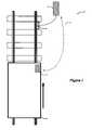
- FIG. 11is a diagram of a field sensor system that can be used to monitor neutral temperature.
- FIGS. 12 a and 12 bshow the configuration of strain gauge circuits on a rail.
- FIG. 13is a block diagram of a field sensor system.
- FIG. 14is a flow chart of the operation of a device in a field sensor system.
- FIG. 15is a flow chart of the operation of a data collection device.
- FIGS. 16 , 17 , 18 , 19 , and 20are screen displays for a Pocket PC-based data collection device.
- FIG. 21is a screen display for a desktop data viewing and analysis application.
- FIG. 22is a diagram of a relational database.
- FIG. 23is a flow chart of the operation of a data viewing and analysis application.
- FIGS. 24 , 25 , and 26are screen displays for a desktop data viewing and analysis application.
- one crucial structure that is subject to eventual detrimental changes and loss of integrityis the rail used to construct the railroads on which trains operate.
- the railused to construct the railroads on which trains operate.
- weather conditions, railroad track maintenance, changes in the track sub-structure or even normal train operationscan have an effect and degrade the structural integrity of railway rail to unsafe levels.
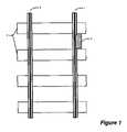
- FIG. 1is a diagram of a portion of railway with rails 1 and 2 and ties 3 .
- a track or field sensor system 4which can be used to monitor various characteristics and conditions of the rail.
- the field sensor system 4is made up of various field sensor system components, which may include electronics, sensors, and other components to facilitate the measurement of various conditions of the rail 1 .
- the field sensor system 4collects data from the structure to be monitored, which in FIG. 1 is the rail 1 . Data relating to the condition of the rail 1 is collected either continuously or periodically, and in some embodiments, the field sensor system 4 stores this data in a storage device or memory located within the field sensor system 4 .
- FIG. 2 a and FIG. 2 bshow a cross sectional diagram of both sides of rail 1 in FIG. 1 .
- various components 5 of the field sensor system 4may be mounted along the web of the rail 1 .
- FIG. 2 billustrates the inboard or inward side of the rail 1 where various components 6 of the field sensor system 4 are mounted along the web of the inner portion of the rail 1 .
- the field sensor system 4may include components 5 , or components 6 , or both.
- the components 5 or 6may be housed in an enclosure that is mounted along the web of the rail 1 .
- additional components of the field sensor system 4may additionally be mounted along one or both sides of the opposing rail 2 . Further, depending on the information required from the rails 1 and 2 , it may also be appropriate to alternatively or additionally place components at other locations along the rail (other than along the web).
- FIG. 3shows an alternate configuration.
- the field sensor system 7is represented by boxes 8 and 9 .
- Some of the components of the field sensor systemare represented by box 8 , which is located on or near the rail 1
- othersare represented by box 9 , which is located a distance away from the rail 1 (e.g., 30 feet).
- communications connection 10which may be a wireless or wireline (cabled) connection.
- the field sensor systemis represented by boxes 11 , 12 , and 13 .
- some of the componentsare located along the rails (see 11 and 12 ), and some components are located a distance away from the track, as represented by box 13 .
- various components of the field sensor system in an embodiment such as that shown in FIG. 4are connected in some fashion (see connections 14 and 15 ).
- FIG. 5shows yet another configuration of the field sensor system, in which some of the field sensor components are located in a crib 16 between the rails 1 and 2 .
- the field sensor systemcomprises, in this embodiment, the crib 16 , and components at the rails 1 and 2 , as represented by the boxes 17 and 18 , all of which are connected by connection 19 .
- the field sensor system 20is made up of crib 16 , components represented by boxes 17 and 18 (mounted along the rails 1 and 2 ), and connection 19 .
- Datais collected from the rails 1 and 2 periodically by the components 17 and 18 , and the data is stored in a storage area located in crib 16 .
- the data stored in structure 16is collected by data collection personnel.
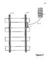
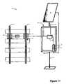
- Data collection personneltravel (often using a vehicle 21 ) to the portion of the track where the field sensor system 20 is located, and use a data collection device 22 to collect the data from the field sensor system 20 . Collection of the data takes place by interfacing the data collection device 22 to the field sensor system 20 .
- This interfacemay be created in a variety of ways, such as through a physical RS-232 connection between the field sensor system 20 (or crib 16 ) and the data collection device 22 , through a USB connection, or through any other means now known or hereafter developed for physically connecting two devices for the purpose of data communication.
- the data collection device 22is able to interface with the field sensor system 20 over a wireless interface, such as Bluetooth, WiFi, or any other popular, proprietary, or otherwise appropriate method now known or hereafter developed.
- the data collection device 22could query the field sensor system 20 for the data it has collected, and some or all of the data can then be transferred to the data collection device 22 .
- a wireless interfaceallows the person collecting the data to avoid leaving his or her vehicle 21 to collect the data.
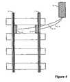
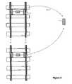
- a field sensor system 23is comprised of components 24 and 25 , and it communicates with a data collection device 26 over a wireless interface 27 in a manner similar to that described in connection with FIG. 6 .
- the data collection device 26is located on a railway vehicle 28 .
- the data stored in the field sensor system 23is collected by the device 26 when the railway vehicle 28 comes close to the field sensor system 23 , such as when it passes that portion of the track where the field sensor system 23 is located.
- the data collection device 26 in the embodiment of FIG. 7is preferably configured to allow collection of data from a variety of field sensor systems 23 located along the railway. Data is collected from each field sensor system as the railway vehicle 28 travels along the track.
- the railway vehicle 28 in FIG. 7could be a railroad car or other vehicle that is adapted for use on the railway.
- the railway vehicle 28is a railroad car or other vehicle that regularly travels on the track for other purposes, so as to reduce the necessity of independent data collection personnel physically visiting each field sensor system solely to collect data from the field sensor system 23 .
- a field sensor system 29is configured in a crib configuration, such as in FIG. 6 .
- the field sensor system 29 in the embodiment of FIG. 8includes the capability to initiate communication over a wireless interface 30 to a data collection device 31 .
- the field sensor system 29 in such an embodimentmay initiate communication with the data collection device 31 periodically, and each time transfer the data it has collected to the data collection device 31 .
- the field sensor system 29may initiate communication with the data collection device 31 only when one or more of a particular set of conditions arise, such as conditions that suggest a degradation of the structural integrity of the rail being monitoried.
- the ability for such communication initiated by the field sensor system 29can be implemented by including within the field sensor system 29 cell or mobile telephony capability, satellite capability, WiFi, or any other known or hereafter developed technique for wireless communication.
- the data collection device 31 in such an embodimentmay be at a distant location, and may also be in a location that allows more than one field sensor system to communicate with it, so that, for example, the data collection device 31 can receive data from field sensor systems 29 and 32 , which monitor different portions of track. See FIG. 8 .
- the datamay then be integrated into a master database that includes data relating to the structure being monitored (e.g., a railway rail) from prior data collection efforts.
- a master databasethat includes data relating to the structure being monitored (e.g., a railway rail) from prior data collection efforts.
- data from field sensor system 29 in one readingis collected by data collection device 31 , and is represented by the data set 33 shown in FIG. 9 .
- the data set 33 from such a collection effortis integrated into a master database 34 along with data sets 35 , 36 , and 37 from prior collection efforts.
- the data in the database 34can then be processed and/or analyzed to determine various characteristics and information about the condition of the structure(s) being monitored.
- the data in database 34can be studied and analyzed to identify any situations where the integrity of the structure(s) being monitored has or is being degraded. In some situations, data from a history of collection efforts can be studied to determine patterns or trends in how the structure being monitored changes over time, or in response to various weather conditions, stresses, or other conditions.
- FIG. 10is a flow chart summarizing a typical process for data logging, collection, and analysis in an attempt to monitor and detect specific conditions that indicate a structure, such as a railway rail, may degrade to a point where it is no longer safe.
- the datacan then be processed and analyzed 40 , perhaps by comparing data from different data collection efforts, or by evaluating data to detect specific structural integrity issues. If any potential structural problems are detected 41 , appropriate actions can be taken 42 to avert any safety hazards, and to repair or replace the affected structure. This process can be repeated indefinitely.
- railway railis subject to expansion and contraction that is proportional to the temperature of the rail.
- railway trackwas constructed of relatively short individual track rails that were fastened together end-to-end using rail joints. Adjacent rails were typically spaced apart at each end with a small gap, which accommodated changes in the rail length.
- most railroadsare constructed of continuously welded rail, so that the gaps between adjacent rails are virtually eliminated. With continuously welded rail, the rail's tendency to change length with changing temperatures is, in a sense, magnified, since there are no natural expansion or contraction joints to allow the rail to expand or contract.
- the rail's tendency to change lengthrepresents a significant safety problem, because if the internal compressive forces on the rail become too great, the rail can buckle or kink (sun kinks). If the tensile forces become too great, the rail can crack and pull apart. Either condition jeopardizes the safety of normal train operations, and in some situations can lead to catastrophic train derailments. Unfortunately, it is often not visually apparent whether a particular rail is under an axial load that is potentially unsafe, so a safety hazard caused by a kinked rail, for example, may arise without much warning.
- One way to address structural problems relating to the expansion and contraction of railway railis to monitor the neutral temperature of the rail, which is defined as the temperature at which the rail is neither in tension or compression.
- the neutral temperature of the railwhich is defined as the temperature at which the rail is neither in tension or compression.
- the railWhen a rail is at its neutral temperature, it has no tendency to change length and has no internal axial force or stress. At temperatures which are cooler than the rail's neutral temperature, the rail is stretched and has an internal tensile force. And at temperatures warmer than the neutral temperature, the rail is squeezed and has an internal compressive force.
- FIG. 11shows a diagram of a field sensor system 43 that can be used to monitor the neutral temperature of rails 1 and 2 .
- the field sensor system 43includes commercially-available strain gauge circuits, mounted on both sides of each rail at the locations designated by boxes 44 and 45 .
- Two commercially-available thermocouple sensor circuits 46 and 47are also used, one thermocouple 46 mounted to the rail 1 , and the other thermocouple 47 mounted in a location that permits the collection of ambient temperature data.
- the output of the components 44 , 45 , 46 , and 47are connected to a module 48 in an enclosure 49 .
- the enclosure 49houses various components of the field sensor system 43 , including the module 48 , an antenna 50 that is used for communicating with a data collection device (not shown), rechargeable batteries 51 , and a charge controller 52 .
- Rechargeable batteries 51such as 12 V DC batteries, power the entire field sensor system 43 .
- the batteriesare recharged using a charge controller 52 and a solar panel 53 , which is mounted on a pole 54 . In some embodiments, it is convenient to mount the enclosure 49 on the solar panel pole 54 .
- FIGS. 12( a ) and 12 ( b )show in more detail the configuration of the strain gauge circuit 44 on rail 1 .
- strain gauge circuitsare implemented by resistors that change resistance as they are stretched or compressed.
- FIGS. 2( a ) and 2 ( b ) and FIGS. 12( a ) and 12 ( b )When mounted in the web of the rail, such as is shown in FIGS. 2( a ) and 2 ( b ) and FIGS. 12( a ) and 12 ( b ), they can be used to determine to what extent the rail has been stretched or compressed in the longitudinal direction.
- FIG. 12( a )shows the strain gauges 55 and 56 mounted in the web on the outboard side of the rail 1 .
- the gaugesare preferably mounted in a Wheatstone bridge configuration, along the side of an imaginary diamond 59 drawn on the web of the rail 1 as shown in FIG. 12( a ).
- the gauges 57 and 58are preferably mounted on the opposite side of the rail (inboard) along a corresponding diamond 60 as shown in FIG. 12( b ).
- FIG. 13is a block diagram of components of the field sensor system 43 shown in FIG. 11 and FIGS. 12( a ) and 12 ( b ).
- the voltages from the north and south strain gauges 44 and 45are each fed into a bridge amplification circuit or signal conditioner 61 and 62 to condition the signal before the data acquisition device 63 can read the voltages.
- the bridge amplification circuits 61 and 62amplify the voltages that come from the strain gauge circuits 44 and 45 .
- the bridge amplifiers 61 and 62also provide current for the strain gage circuits 44 and 45 .
- the strain gaugesare preferably calibrated when installed, and such calibration may require the current neutral temperature of the rail, which then is used to determine an offset voltage (V o ) that is used in calculating neutral temperature. Calibration may not be necessary for some embodiments, such as for monitoring fluctuations in the neutral temperature.
- any appropriate method now known or hereafter developed for placing a rail at a known neutral temperature or measuring the neutral temperature of an existing railcan be used for calibration.
- the railis simply placed at a known neutral temperature by cutting and re-welding it so that it is not in compression or tension.
- the current rail temperatureis then the neutral temperature of the rail that can be used for calibration.
- there are also ways to measure the neutral temperature of an existing railhowever. For example, one method involves cutting the rail to determine the distance it expands or contracts, and then from this information, calculating its initial neutral temperature. In another method, a portion of existing rail is unclipped from its ties, and the rail is raised several inches. A Verse is used to determine the amount of force is required to raise the rail a certain distance. From this information, the neutral temperature can be determined.
- thermocouple signal conditioners 64 and 65that amplify the thermocouple voltages so they can be read by the data acquisition device 63 .
- the signal conditioners 64 and 65also will preferably contain a cold junction compensator that adjusts for the cold junction created when connecting the thermocouple wire to the signal conditioner. In general, no calibration is necessary for the thermocouple signal conditioners.
- an auto calibration R-Cal resistor circuit 66is used to provide some assurance that data quality is high.
- the R-Cal resistoris used to ensure that the resistance measured by the strain gauges shown in FIGS. 12( a ) and 12 ( b ) is consistent with calibration.
- the R-Cal resistorcan be installed so that it can temporarily replace the resistance provided by the strain gauges (e.g., 55 and 56 ).
- By reading the resistance provided by the R-Cal resistor(a known quantity) it can be determined whether the resistance provided by the strain gauges (e.g., 55 and 56 ) is accurate. This measurement may be taken periodically (e.g., each strain gauge reading or perhaps once per day) or on demand to ensure data quality.
- a microprocessor 67 and memory 68are used for storing data from the data acquisition module 63 .
- the data acquisition module 63 , the microprocessor 67 , and the data memory 68may, in some embodiments, be implemented using a commercially-available data logger device 69 , such as an Adam-5510 manufactured by Advantech of Cincinnati, Ohio. In other embodiments, the data logger device 69 could be integrated as one or more components, perhaps on a single circuit board.
- a Bluetooth wireless interface module 70is controlled by the microprocessor 67 to communicate with a PDA or Pocket PC or other portable device 71 , which has a Bluetooth communications module 72 and is executing an application program 73 .
- An insertable storage card 74such as a Secure Digital card, may also be used as storage for the application program 73 .
- the components used to construct the field sensor system 43are chosen or designed so that they facilitate replacement or repair of the system 43 .
- the module 48might be designed so that it can be easily replaced in the event that one or more components of the module 48 fails.
- a field sensor system having a faulty module 48may be remedied by disconnecting the sensors, power, and antenna cables from the faulty module 48 , and replacing it with a substitute module having the same or similar connections, so that the same sensors, power, and antenna cables can be easily reattached.
- the faulty module 48may then be sent to an appropriate location for diagnostic testing, if desired.
- T( V ⁇ A ) ⁇ B
- the sensors 44 , 45 , 46 , and 47are sampled periodically at a defined interval, such as once each hour, although this time period can be configured as desired.
- the data acquisition device 63converts the analog voltages to digital voltages for each of the four sensor readings.
- Software in the microprocessor 67stores these voltages in the memory 68 along with a time stamp of when they were collected.
- the sensor readingsare stored in the field sensor's memory 68 until they can be downloaded to a data collection device 71 .
- a reading counter maintained in the memory 68is incremented so that the number of samples that are stored in the memory 68 can be ascertained.
- Datais collected from the memory 68 using a handheld device, such as a Pocket PC device 71 with wireless communication capability.
- the Pocket PC device 71executes a data collection application (represented by 73 in FIG. 13 ) that enables wireless communication with the field sensor system 43 .
- datais transmitted to Pocket PC 71 over a wireless signal using the Bluetooth wireless communications protocol.
- the module 48includes a Bluetooth RS-232 module 70 that is attached to the RS-232 port of the microprocessor 67
- the Pocket PC 71includes a Bluetooth radio module 72 .
- the RS-232 module 70 and the module 72 in the Pocket PCallow wireless communication as if an RS-232 cable linked the Pocket PC 71 and the microprocessor 67 .
- the Pocket PC 71when the data collection application 73 is executing on a Pocket PC 71 , and a user brings the Pocket PC 71 within the range (approximately 10 meters) of the Bluetooth RS-232 Module 70 , the Pocket PC 71 automatically connects to the field sensor system 43 (module 70 ) and establishes a connection.
- the system parameters for the field sensor system 43 as well as all of the data that has been collected in memory 68 since the last downloadare automatically downloaded to the Pocket PC 71 upon establishing an initial communications link. This data is stored in available storage in the Pocket PC 71 .
- system parameters for the field sensor system 43it is useful to store the system parameters for the field sensor system 43 in the memory 68 . Storing system parameters for the field sensor system 43 in the memory 68 , and making such system parameters available to be downloaded by any Pocket PC 71 device that may be used for collection of data ensures that data collection personnel can use any Pocket PC running the data collection application 73 to download the data. In other words, multiple Pocket PCs can be used interchangeably in some embodiments to collect data from various field sensor systems.
- the system parameters stored in the field sensor system 43may include: (1) the system date and time as maintained by the field sensor system, (2) field sensor system name, (3) field sensor system identifier (e.g., a number or code), (4) number of records of normal data collected, (5) number of records of archive data collected, (6) strain gauge voltage offsets for each rail, (7) initial neutral temperature for each rail (when the rail was installed or most recent calibration), and (8) rate at which data is sampled.
- field sensor system namee.g., a number or code
- the memory 68may also then be cleared.
- the Pocket PC 71can also specify specific data to be retrieved from or written to the field sensor system 43 by sending ASCII commands to the microprocessor 67 over the Bluetooth connection.
- FIG. 14is a flow chart of the operation of data logger device 69 in the embodiment of FIG. 11 and FIG. 13 .
- memory and various variablessuch as a sample counter
- the systementers a loop at 76 .
- the data from the sensorsis collected 77 through the data acquisition device 63 and stored in memory 68 for later collection.
- the serial port buffer for the microprocessor 67is continuously monitored 78 for data representing a command sent by a Pocket PC device 71 . If such data is present at the serial port, appropriate action is taken in response to the command.
- the microprocessoris capable of performing a variety of actions, some of which involve reading from and writing to memory 67 . See 79 in FIG. 14 .
- FIG. 15is a flow chart of the operation of the data collection application 73 running in the Pocket PC 71 used by data collection personnel in FIG. 13 .
- the Bluetooth capability or other communications capabilityis loaded and initialized.
- data collection personnelstarts the data collection application 73 , he or she has typically traveled to a location near a field sensor system 43 , and the Pocket PC 71 enters a loop searching for another Bluetooth device in the area 81 .
- the Pocket PC 71connects to it through the Bluetooth connection 83 .
- the system parameters for the field sensor system 43 and any available dataare downloaded 84 to the Pocket PC device.
- FIG. 16shows the display of a Pocket PC device 71 in an embodiment such as that illustrated in FIG. 15 .
- the displayis shown after the Pocket PC 71 has made an initial connection to a field sensor system having the name “LSD 107 .”
- FIG. 16also shows that 151 data records are being read from the LSD 107 field sensor system.
- the Pocket PC 71calculates the neutral temperatures for both the north and south rails, preferably using the most recent data record, and this calculation is displayed, as shown in FIG. 17 . (In some embodiments, it is possible that the neutral temperature calculation is performed by the data logger device 69 , or by other logic.)
- Selecting the “Options” menu at the bottom of the screen in FIG. 16provides the ability to (1) exit the program, and (2) view the system parameters for the field sensor system. Selecting the option to display system parameters causes a screen such as that shown in FIG. 18 to appear. From this screen, it is possible to change the indicated parameters by changing the displayed item and then selecting the “write” button to write the data to the field sensor system. The data is written by communicating with the microprocessor 67 over the wireless Bluetooth connection.
- the “Data” menu item in FIGS. 16 and 17provides the ability to display (1) the current neutral temperature calculation, or (2) historical data retrieved by the Pocket PC device 71 . Selecting the first option causes a screen such as that shown in FIG. 19 to be displayed, which shows the neutral temperature calculation in FIG. 17 , as well as some of the underlying data used to calculate the neutral temperature.
- Selecting the second optioncauses a screen such as that shown in FIG. 20 to be displayed.
- the screen in FIG. 20shows the raw data collected by the field sensor system, and the time each reading was taken.
- the reading date/time 87 shown in the center of the screenis the date the Pocket PC 71 downloaded the data from the field sensor system 43 , and the time entries shown in the grid are the actual times the sensor measurements for the indicated site and rail were taken by the field sensor system 43 .
- Data collection personnelcan select other reading dates 87 stored on the Pocket PC 71 by selecting the desired date from the drop-down menu associated with 87 shown in FIG.
- the application running on the Pocket PC 71is stored on a Secure Digital (or other) memory card 74 that can be inserted and read by the Pocket PC. This allows the software to be used on virtually any Bluetooth-enabled Pocket PC device by simply inserting the memory card 74 , and in general, without any additional configuration or software installation.
- the new datacan be integrated into a master database where other readings are stored. In some embodiments, this is done by synchronizing the Pocket PC device using software such as Microsoft's ActiveSync to transfer the data on the Pocket PC to a desktop or other computer where a master database is maintained.
- FIG. 21shows a screen from a desktop application that can be used in an embodiment of the present invention to analyze the data collected from various field sensor systems.
- the applicationhas a pull-down menu 88 and a data display area 89 .
- the data shown in the display area 89 in FIG. 21relates to various readings from a number of field sensor systems deployed on a railroad.
- the subdivisions listed in the first column 90identify a section of track, which may include one or more field sensor systems.
- the site name column 91lists the identifier for each field sensor system located in the corresponding subdivision.
- Column 92lists the date and time that a reading on each rail was last taken using a data collection device.
- the current force 93 and current neutral temperature 94 as calculated for the last data available for each siteis also listed, along with the initial neutral temperature of the rail 95 , which is determined when the rail was installed, or when the field sensor system was last or previously calibrated.
- the historical maximum neutral temperatureis listed 96 , along with the current difference (i.e., delta) 97 between the current neutral temperature 94 and the initial neutral temperature 95 are also shown for each of the two rails at each site.
- the difference between the maximum neutral temperature 96 and the initial neutral temperature 95is also shown 98 .
- color or other visual indiciamay be used to highlight data that may be of interest to the user, such as measurements that suggest a significant change in neutral temperature.
- the data shown in FIG. 21is preferably taken from a relational database, such as the database represented by the diagram in FIG. 22 .
- Shown in FIG. 21are five tables 99 , 100 , 101 , 102 , and 103 .
- Table 99is used for storing a list of Subdivisions and characteristics associated with each Subdivision.
- Each Subdivisionwhich generally refers to a section of railway track, has a name, a location, and may have a contact person and phone number.
- Associated with each Subdivisionmay be one or more Sites, which are listed in the Sites table 100 .
- For each Siteone or more Readings may be stored in the Readings table 101 , and each Reading may have associated with it one or more data entries, which are stored in the Data table 102 .
- a System Parameters table 103is also shown in FIG. 22 .
- FIG. 23is a flowchart of the operation of the desktop application of FIG. 21 .
- the Pocket PCis queried to determine whether any new data (typically in the form of data files or text files) is available 105 . If any data is available, the data is copied from the Pocket PC to the desktop PC executing the desktop application 106 . The data may then be integrated 107 into a database, such as the one illustrated in FIG. 22 . The files may then be stored in an archival location on the PC or elsewhere 108 , and the files may also be removed from the Pocket PC. During this process, the desktop PC user may receive visual or other confirmation as these steps are being completed.
- the application window for the desktop application shown in FIG. 21has a pull-down menu 88 , which can be used to access a number of functions.
- the pull-down menu 88includes a System menu 110 , an iPaq menu 111 , and a View menu 112 , as represented in FIG. 23 .
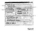
- the usermay either view system parameters, which causes a dialog box such as that shown in FIG. 24 to appear, or the user may exit the program.
- the dialog box of FIG. 24provides the opportunity to alter the way in which the desktop application of FIG. 23 operates.
- the usercan modify the location where data files are stored or archived 113 , and can modify the way data is transferred and otherwise handled 114 .
- the automatic synchronization feature(see 104 in FIG. 23 ) can be enabled in this dialog box, and data may be automatically deleted from the Pocket PC after transfer (see 106 in FIG. 23 ).
- the desktop applicationcan be configured to send an email including some or all of the data to a desired email address.
- the dialog box of FIG. 24also provides the ability to modify the data history range, or the number of days data is displayed in the display window of FIG. 26 . Also, the color thresholds for the data displayed in FIG. 21 may also be configured in the dialog box of FIG. 24 . See 115 of FIG. 24 .
- iPaqis a popular Pocket PC device manufactured by Hewlett-Packard Company, and is used here synonymously with “Pocket PC”
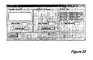
- a dialog boxsuch as that shown in FIG. 25 to appear, which can be used to manually retrieve data from the Pocket PC, similar to the manner in which the data is retrieved through the synchronization procedure 105 , 106 , 107 , and 108 .
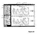
- Selecting the View menu 112provides the option to view the data in the Subdivisions and Sites tables, which are illustrated as part of the database in FIG. 22 , and also to view and/or chart data from one or more sites in a manner shown in FIG. 26 .
- the data viewing screen in FIG. 26allows both the graphical display 117 and text-grid display 118 of data for two different rails.
- the rails displayedmay simply be the north and south rails from the same Site, as is shown in FIG. 26 , or the rails may from different sites.
- the Site drop down menus 119 and 121 and the Rail ID drop-down menus 120 and 122the user can select the desired data for display.
- graphs of the neutral temperature 123 , the rail temperature 124 , and the ambient temperature 125 over timemay be displayed for each of the displayed rails.
- the force on the rail 126may also be displayed, if desired.
- the neutral temperature of the tracktends to vary over a twenty-four hour period, rising as the ambient temperature rises, and falling as the ambient temperature falls.
- railis installed so that it is securely fastened to the ground, and is given little, if any, room to move.
- the neutral temperaturewould, theoretically, not fluctuate during the day.
- the neutral temperaturemay be an indication that the track has some room to relieve some axial forces that it is subject to, and presumably may not be completely secured.
- a trackmay be insufficiently secured to the ground, or loose, which is a condition that can cause problems for railroads, and perhaps additional safety issues.
- some of the embodiments and systems described hereinmay also be used to detect not only the internal forces in the rail, but also the extent to which the rail is securely attached to the ground.
- Appendices A, B, and Care lists of files containing source code for three applications.
- Appendix Ais a list of files from an application designed to execute on a data logger module (Adam-5510), and is written in C.
- Appendix Bis a list of files for an application written in Microsoft Embedded Visual C++ that executes on a Pocket PC handheld device.
- Appendix Bis a list of files for a Microsoft Windows desktop application written in Visual Basic. The software in these appendices can be used in a Pocket PC-based wireless neutral temperature measurement system, as is described herein, particularly in connection with FIG. 16 to FIG. 26 .
Landscapes
- Physics & Mathematics (AREA)
- General Physics & Mathematics (AREA)
- Engineering & Computer Science (AREA)
- Mechanical Engineering (AREA)
- Arrangements For Transmission Of Measured Signals (AREA)
Abstract
Description
NT=T−P/(Area×E×a)
- Where:
- NT is the neutral temperature of the rail,
- T is the actual temperature of the rail,
- P is the internal longitudinal force in the rail,
- Area is the area of the rail cross-section,
- E is the Modulus of Elasticity for the track system,
- a is the Coefficient of Thermal Expansion for steel.
T=(V×A)×B
- T is the temperature of the rail (Fahrenheit),
- V is the voltage from the signal conditioners,
- A is the temperature conversion scale constant,
- B is the temperature conversion offset constant.
P=(Vs+Vo)×C
- Where:
- P is the force (lbs.)
- Vsis the strain gauge voltage,
- Vois the voltage offset in volts (from calibration),
- C is the voltage to force conversion constant.
Claims (16)
Priority Applications (3)
| Application Number | Priority Date | Filing Date | Title |
|---|---|---|---|
| US10/979,870US7392117B1 (en) | 2003-11-03 | 2004-11-02 | Data logging, collection, and analysis techniques |
| US12/138,617US7698028B1 (en) | 2003-11-03 | 2008-06-13 | Data logging, collection, and analysis techniques |
| US12/716,247US8155809B1 (en) | 2003-11-03 | 2010-03-02 | Data logging, collection, and analysis techniques |
Applications Claiming Priority (2)
| Application Number | Priority Date | Filing Date | Title |
|---|---|---|---|
| US51683003P | 2003-11-03 | 2003-11-03 | |
| US10/979,870US7392117B1 (en) | 2003-11-03 | 2004-11-02 | Data logging, collection, and analysis techniques |
Related Child Applications (1)
| Application Number | Title | Priority Date | Filing Date |
|---|---|---|---|
| US12/138,617ContinuationUS7698028B1 (en) | 2003-11-03 | 2008-06-13 | Data logging, collection, and analysis techniques |
Publications (1)
| Publication Number | Publication Date |
|---|---|
| US7392117B1true US7392117B1 (en) | 2008-06-24 |
Family
ID=39530082
Family Applications (3)
| Application Number | Title | Priority Date | Filing Date |
|---|---|---|---|
| US10/979,870Active2026-04-04US7392117B1 (en) | 2003-11-03 | 2004-11-02 | Data logging, collection, and analysis techniques |
| US12/138,617Expired - LifetimeUS7698028B1 (en) | 2003-11-03 | 2008-06-13 | Data logging, collection, and analysis techniques |
| US12/716,247Expired - LifetimeUS8155809B1 (en) | 2003-11-03 | 2010-03-02 | Data logging, collection, and analysis techniques |
Family Applications After (2)
| Application Number | Title | Priority Date | Filing Date |
|---|---|---|---|
| US12/138,617Expired - LifetimeUS7698028B1 (en) | 2003-11-03 | 2008-06-13 | Data logging, collection, and analysis techniques |
| US12/716,247Expired - LifetimeUS8155809B1 (en) | 2003-11-03 | 2010-03-02 | Data logging, collection, and analysis techniques |
Country Status (1)
| Country | Link |
|---|---|
| US (3) | US7392117B1 (en) |
Cited By (42)
| Publication number | Priority date | Publication date | Assignee | Title |
|---|---|---|---|---|
| US20070044566A1 (en)* | 2004-07-26 | 2007-03-01 | Salient Systems, Inc. | Stress monitoring system for railways |
| US20070073453A1 (en)* | 2005-09-29 | 2007-03-29 | Siemens Aktiengesellschaft | System architecture for controlling and monitoring components of a railroad safety installation |
| US20070078574A1 (en)* | 2005-09-30 | 2007-04-05 | Davenport David M | System and method for providing access to wireless railroad data network |
| US20080195265A1 (en)* | 2004-05-03 | 2008-08-14 | Sti Rail Pty Ltd | Train Integrity Network System |
| US20090173839A1 (en)* | 2008-01-03 | 2009-07-09 | Iwapi Inc. | Integrated rail efficiency and safety support system |
| US20090228155A1 (en)* | 2007-11-23 | 2009-09-10 | Slifkin Timothy P | Display and management of events in transport refrigeration units |
| USD601561S1 (en) | 2008-09-22 | 2009-10-06 | Carrier Corporation | Data logging device having tethered data communication interface |
| US20090277998A1 (en)* | 2008-05-07 | 2009-11-12 | James Kiss | Methods and system for detecting railway vacancy |
| US20100182163A1 (en)* | 2005-02-25 | 2010-07-22 | Iwapi Inc. | Smart modem device for vehicular and roadside applications |
| US20110313686A1 (en)* | 2009-03-05 | 2011-12-22 | Product & Process Development, S.L. | Method for applying extensometric sensors in railway tracks |
| US8178242B2 (en) | 2004-10-29 | 2012-05-15 | Medtronic, Inc. | Lithium-ion battery |
| US8275522B1 (en) | 2007-06-29 | 2012-09-25 | Concaten, Inc. | Information delivery and maintenance system for dynamically generated and updated data pertaining to road maintenance vehicles and other related information |
| US8902081B2 (en) | 2010-06-02 | 2014-12-02 | Concaten, Inc. | Distributed maintenance decision and support system and method |
| US8914171B2 (en) | 2012-11-21 | 2014-12-16 | General Electric Company | Route examining system and method |
| US9077022B2 (en) | 2004-10-29 | 2015-07-07 | Medtronic, Inc. | Lithium-ion battery |
| US9255913B2 (en) | 2013-07-31 | 2016-02-09 | General Electric Company | System and method for acoustically identifying damaged sections of a route |
| US9287580B2 (en) | 2011-07-27 | 2016-03-15 | Medtronic, Inc. | Battery with auxiliary electrode |
| US20160356661A1 (en)* | 2014-01-21 | 2016-12-08 | Thales Deutschland Gmbh | Rail measuring system |
| EP3109126A1 (en)* | 2015-06-24 | 2016-12-28 | VolkerRail Nederland BV | Monitoring with a lpwan data logger |
| US9587321B2 (en) | 2011-12-09 | 2017-03-07 | Medtronic Inc. | Auxiliary electrode for lithium-ion battery |
| US9671358B2 (en) | 2012-08-10 | 2017-06-06 | General Electric Company | Route examining system and method |
| US9733625B2 (en) | 2006-03-20 | 2017-08-15 | General Electric Company | Trip optimization system and method for a train |
| DE102016002692A1 (en)* | 2016-03-08 | 2017-09-14 | Goldschmidt Thermit Gmbh | Method for determining the neutral temperature in elongate workpieces |
| US9828010B2 (en) | 2006-03-20 | 2017-11-28 | General Electric Company | System, method and computer software code for determining a mission plan for a powered system using signal aspect information |
| US9864957B2 (en) | 2007-06-29 | 2018-01-09 | Concaten, Inc. | Information delivery and maintenance system for dynamically generated and updated data pertaining to road maintenance vehicles and other related information |
| US9950722B2 (en) | 2003-01-06 | 2018-04-24 | General Electric Company | System and method for vehicle control |
| US9956974B2 (en) | 2004-07-23 | 2018-05-01 | General Electric Company | Vehicle consist configuration control |
| US10167003B1 (en) | 2015-05-15 | 2019-01-01 | Voestalpine Signaling Usa Inc. | Automated rail inspection system |
| AT520438A4 (en)* | 2018-03-12 | 2019-04-15 | Plasser & Theurer Export Von Bahnbaumaschinen Gmbh | System for detecting a mechanical tensile / compressive stress of a rail |
| USRE47395E1 (en)* | 2010-05-19 | 2019-05-21 | L.B. Foster Rail Technologies Canada, Ltd. | Optimizing rail track performance |
| US10308265B2 (en) | 2006-03-20 | 2019-06-04 | Ge Global Sourcing Llc | Vehicle control system and method |
| EP3557193A1 (en)* | 2018-04-18 | 2019-10-23 | Siemens Mobility GmbH | Sensor device and method for inspecting a rail section |
| US10582187B2 (en) | 2015-02-20 | 2020-03-03 | Tetra Tech, Inc. | 3D track assessment method |
| US20200070862A1 (en)* | 2018-08-30 | 2020-03-05 | Voestalpine Signaling Usa Inc. | Railcar acoustic monitoring system and method of use |
| US10625760B2 (en) | 2018-06-01 | 2020-04-21 | Tetra Tech, Inc. | Apparatus and method for calculating wooden crosstie plate cut measurements and rail seat abrasion measurements based on rail head height |
| IT201800020269A1 (en)* | 2018-12-20 | 2020-06-20 | Lef Holding S R L | An isolated joint control system along a railway line |
| US10728988B2 (en) | 2015-01-19 | 2020-07-28 | Tetra Tech, Inc. | Light emission power control apparatus and method |
| US10730538B2 (en) | 2018-06-01 | 2020-08-04 | Tetra Tech, Inc. | Apparatus and method for calculating plate cut and rail seat abrasion based on measurements only of rail head elevation and crosstie surface elevation |
| US10807623B2 (en) | 2018-06-01 | 2020-10-20 | Tetra Tech, Inc. | Apparatus and method for gathering data from sensors oriented at an oblique angle relative to a railway track |
| JP2021501079A (en)* | 2017-10-30 | 2021-01-14 | コヌクス ゲーエムベーハー | Data fusion concept |
| US10908291B2 (en) | 2019-05-16 | 2021-02-02 | Tetra Tech, Inc. | System and method for generating and interpreting point clouds of a rail corridor along a survey path |
| US11377130B2 (en) | 2018-06-01 | 2022-07-05 | Tetra Tech, Inc. | Autonomous track assessment system |
Families Citing this family (13)
| Publication number | Priority date | Publication date | Assignee | Title |
|---|---|---|---|---|
| US20100194533A1 (en)* | 2009-01-30 | 2010-08-05 | Sullivan Henry W | Method and apparatus for encoding railroad ties and other railroad track components |
| US20120203402A1 (en)* | 2011-02-07 | 2012-08-09 | International Business Machines Corporation | Intelligent Railway System for Preventing Accidents at Railway Passing Points and Damage to the Rail Track |
| US9405914B2 (en) | 2011-05-10 | 2016-08-02 | Thales Canada Inc. | Data analysis system |
| ES2711077T3 (en) | 2012-04-12 | 2019-04-30 | Progress Rail Services Corp | Detection and signaling method of a hot box condition |
| EP2650190A1 (en)* | 2012-04-12 | 2013-10-16 | Progress Rail Services Corporation | Device for detecting a hot box or hot wheel condition |
| US9222904B2 (en)* | 2012-08-13 | 2015-12-29 | Harold Harrison | Method and apparatus for detecting track failure |
| US9481348B2 (en)* | 2012-09-20 | 2016-11-01 | Wabtec Holding Corp. | System and method for addressing a pneumatic emergency in a helper locomotive |
| US9441307B2 (en) | 2013-12-06 | 2016-09-13 | Saudi Arabian Oil Company | Cathodic protection automated current and potential measuring device for anodes protecting vessel internals |
| US9663127B2 (en) | 2014-10-28 | 2017-05-30 | Smartdrive Systems, Inc. | Rail vehicle event detection and recording system |
| US9902410B2 (en)* | 2015-01-08 | 2018-02-27 | Smartdrive Systems, Inc. | System and method for synthesizing rail vehicle event information |
| US9487222B2 (en) | 2015-01-08 | 2016-11-08 | Smartdrive Systems, Inc. | System and method for aggregation display and analysis of rail vehicle event information |
| US9296401B1 (en) | 2015-01-12 | 2016-03-29 | Smartdrive Systems, Inc. | Rail vehicle event triggering system and method |
| US10351150B1 (en)* | 2015-05-29 | 2019-07-16 | Carnegie Mellon University | System to enable rail infrastructure monitoring through the dynamic response of an operational train |
Citations (23)
| Publication number | Priority date | Publication date | Assignee | Title |
|---|---|---|---|---|
| US4701866A (en) | 1984-12-07 | 1987-10-20 | Battelle Memorial Institute | Wheel load measurement |
| US4755238A (en) | 1982-02-19 | 1988-07-05 | Unimetal | Straightened rail |
| US5098080A (en) | 1990-12-19 | 1992-03-24 | Xerox Corporation | Ski jump stack height sensor |
| US5161891A (en) | 1991-02-12 | 1992-11-10 | Practical Transportation, Inc. | Process for determining and controlling railroad rail's neutral temperature to prevent track buckling and rail fractures |
| US5386727A (en) | 1992-06-02 | 1995-02-07 | Herzog Contracting Corporation | Dynamic rail longitudinal stress measuring system |
| US5529267A (en) | 1995-07-21 | 1996-06-25 | Union Switch & Signal Inc. | Railway structure hazard predictor |
| US5680054A (en) | 1996-02-23 | 1997-10-21 | Chemin De Fer Qns&L | Broken rail position detection using ballast electrical property measurement |
| US5713540A (en) | 1996-06-26 | 1998-02-03 | At&T Corp. | Method and apparatus for detecting railway activity |
| US5743495A (en) | 1997-02-12 | 1998-04-28 | General Electric Company | System for detecting broken rails and flat wheels in the presence of trains |
| US5786750A (en)* | 1996-05-10 | 1998-07-28 | The United States Of America As Represented By The Secretary Of The Navy | Pilot vehicle which is useful for monitoring hazardous conditions on railroad tracks |
| US5941482A (en)* | 1998-03-23 | 1999-08-24 | Thermal-Flex Systems, Inc. | Heating cable assembly and connector for railroad switch heating system |
| US5992241A (en)* | 1995-05-09 | 1999-11-30 | Magyar Allamvasutak Reszvenytarsasag | Method and device for determining the neutral temperature of welded tracks |
| US6026687A (en) | 1995-07-14 | 2000-02-22 | Jury; Brent Felix | Stress testing and relieving method and apparatus |
| US6216985B1 (en) | 1997-08-29 | 2001-04-17 | Robert Douglas Stephens | Railway hazard acoustic sensing, locating, and alarm system |
| US20010045495A1 (en) | 1999-03-31 | 2001-11-29 | Leslie E. Olson | Fiber optic rail monitoring apparatus and method |
| US6405141B1 (en) | 2000-03-02 | 2002-06-11 | Ensco, Inc. | Dynamic track stiffness measurement system and method |
| US6434452B1 (en)* | 2000-10-31 | 2002-08-13 | General Electric Company | Track database integrity monitor for enhanced railroad safety distributed power |
| US6570497B2 (en) | 2001-08-30 | 2003-05-27 | General Electric Company | Apparatus and method for rail track inspection |
| US20040122569A1 (en) | 1999-06-15 | 2004-06-24 | Andian Technologies Ltd. | Geometric track and track/vehicle analyzers and methods for controlling railroad systems |
| US6813581B1 (en)* | 2003-03-26 | 2004-11-02 | Union Pacific Railroad Company | Statistical and trend analysis of railroad bearing temperatures |
| US6951132B2 (en) | 2003-06-27 | 2005-10-04 | General Electric Company | Rail and train monitoring system and method |
| US20060020375A1 (en) | 2004-07-26 | 2006-01-26 | Salient Systems, Inc. | System and method for determining rail safety limits |
| US20060059992A1 (en) | 2002-09-20 | 2006-03-23 | Jury Brent F | Apparatus for and methods of stress testing metal components |
Family Cites Families (20)
| Publication number | Priority date | Publication date | Assignee | Title |
|---|---|---|---|---|
| US4578665A (en)* | 1982-04-28 | 1986-03-25 | Yang Tai Her | Remote controlled surveillance train car |
| DE3503347A1 (en)* | 1985-02-01 | 1986-08-14 | Dr.Ing.H.C. F. Porsche Ag, 7000 Stuttgart | DEVICE FOR WIRELESS MEASURING SIGNAL TRANSMISSION |
| US4728063A (en)* | 1986-08-07 | 1988-03-01 | General Signal Corp. | Railway signalling system especially for broken rail detection |
| US5446452A (en)* | 1993-02-05 | 1995-08-29 | Litton; Charles J. | Temperature monitoring system |
| US5987979A (en)* | 1996-04-01 | 1999-11-23 | Cairo Systems, Inc. | Method and apparatus for detecting railtrack failures by comparing data from a plurality of railcars |
| US5956664A (en)* | 1996-04-01 | 1999-09-21 | Cairo Systems, Inc. | Method and apparatus for monitoring railway defects |
| US5627508A (en)* | 1996-05-10 | 1997-05-06 | The United States Of America As Represented By The Secretary Of The Navy | Pilot vehicle which is useful for monitoring hazardous conditions on railroad tracks |
| AU751020B2 (en)* | 1997-03-17 | 2002-08-08 | Ge-Harris Railways Electronics, L.L.C. | A communications system and method for interconnected networks having a linear topology, especially railways |
| AU6872398A (en)* | 1997-03-31 | 1998-10-22 | Whitaker Corporation, The | Unidirectional telemetry system |
| US6681160B2 (en)* | 1999-06-15 | 2004-01-20 | Andian Technologies Ltd. | Geometric track and track/vehicle analyzers and methods for controlling railroad systems |
| US6175784B1 (en)* | 1999-08-09 | 2001-01-16 | Honeywell, Inc. | Remotely operated rail car status monitor and control system |
| US7219067B1 (en)* | 1999-09-10 | 2007-05-15 | Ge Harris Railway Electronics Llc | Total transportation management system |
| US7026941B1 (en)* | 2001-03-01 | 2006-04-11 | Netquest Services, Llc | System and method for measuring a plurality of physical variables from a remote location |
| JP3647767B2 (en)* | 2001-04-25 | 2005-05-18 | 株式会社日立製作所 | Train operation control system |
| US6970100B2 (en)* | 2001-07-05 | 2005-11-29 | Long Range Systems, Inc. | Temperature tag and system for monitoring, recording, and reporting temperature readings |
| DE50204471D1 (en)* | 2002-07-09 | 2006-02-16 | Lenz Elektronik Gmbh | Method and device for the digital control of electrical consumers of a model railway installation |
| US6823242B1 (en)* | 2002-09-23 | 2004-11-23 | Norfolk Southern Corporation | Method and apparatus for monitoring wheel/brake performance |
| JP2005106802A (en)* | 2003-07-10 | 2005-04-21 | Canon Inc | Environmental sensor, environmental measuring device and environmental measuring system |
| US6980124B2 (en)* | 2003-07-15 | 2005-12-27 | Autosafe International, Inc. | Wireless security, telemetry and control system |
| US7226021B1 (en)* | 2005-12-27 | 2007-06-05 | General Electric Company | System and method for detecting rail break or vehicle |
- 2004
- 2004-11-02USUS10/979,870patent/US7392117B1/enactiveActive
- 2008
- 2008-06-13USUS12/138,617patent/US7698028B1/ennot_activeExpired - Lifetime
- 2010
- 2010-03-02USUS12/716,247patent/US8155809B1/ennot_activeExpired - Lifetime
Patent Citations (23)
| Publication number | Priority date | Publication date | Assignee | Title |
|---|---|---|---|---|
| US4755238A (en) | 1982-02-19 | 1988-07-05 | Unimetal | Straightened rail |
| US4701866A (en) | 1984-12-07 | 1987-10-20 | Battelle Memorial Institute | Wheel load measurement |
| US5098080A (en) | 1990-12-19 | 1992-03-24 | Xerox Corporation | Ski jump stack height sensor |
| US5161891A (en) | 1991-02-12 | 1992-11-10 | Practical Transportation, Inc. | Process for determining and controlling railroad rail's neutral temperature to prevent track buckling and rail fractures |
| US5386727A (en) | 1992-06-02 | 1995-02-07 | Herzog Contracting Corporation | Dynamic rail longitudinal stress measuring system |
| US5992241A (en)* | 1995-05-09 | 1999-11-30 | Magyar Allamvasutak Reszvenytarsasag | Method and device for determining the neutral temperature of welded tracks |
| US6026687A (en) | 1995-07-14 | 2000-02-22 | Jury; Brent Felix | Stress testing and relieving method and apparatus |
| US5529267A (en) | 1995-07-21 | 1996-06-25 | Union Switch & Signal Inc. | Railway structure hazard predictor |
| US5680054A (en) | 1996-02-23 | 1997-10-21 | Chemin De Fer Qns&L | Broken rail position detection using ballast electrical property measurement |
| US5786750A (en)* | 1996-05-10 | 1998-07-28 | The United States Of America As Represented By The Secretary Of The Navy | Pilot vehicle which is useful for monitoring hazardous conditions on railroad tracks |
| US5713540A (en) | 1996-06-26 | 1998-02-03 | At&T Corp. | Method and apparatus for detecting railway activity |
| US5743495A (en) | 1997-02-12 | 1998-04-28 | General Electric Company | System for detecting broken rails and flat wheels in the presence of trains |
| US6216985B1 (en) | 1997-08-29 | 2001-04-17 | Robert Douglas Stephens | Railway hazard acoustic sensing, locating, and alarm system |
| US5941482A (en)* | 1998-03-23 | 1999-08-24 | Thermal-Flex Systems, Inc. | Heating cable assembly and connector for railroad switch heating system |
| US20010045495A1 (en) | 1999-03-31 | 2001-11-29 | Leslie E. Olson | Fiber optic rail monitoring apparatus and method |
| US20040122569A1 (en) | 1999-06-15 | 2004-06-24 | Andian Technologies Ltd. | Geometric track and track/vehicle analyzers and methods for controlling railroad systems |
| US6405141B1 (en) | 2000-03-02 | 2002-06-11 | Ensco, Inc. | Dynamic track stiffness measurement system and method |
| US6434452B1 (en)* | 2000-10-31 | 2002-08-13 | General Electric Company | Track database integrity monitor for enhanced railroad safety distributed power |
| US6570497B2 (en) | 2001-08-30 | 2003-05-27 | General Electric Company | Apparatus and method for rail track inspection |
| US20060059992A1 (en) | 2002-09-20 | 2006-03-23 | Jury Brent F | Apparatus for and methods of stress testing metal components |
| US6813581B1 (en)* | 2003-03-26 | 2004-11-02 | Union Pacific Railroad Company | Statistical and trend analysis of railroad bearing temperatures |
| US6951132B2 (en) | 2003-06-27 | 2005-10-04 | General Electric Company | Rail and train monitoring system and method |
| US20060020375A1 (en) | 2004-07-26 | 2006-01-26 | Salient Systems, Inc. | System and method for determining rail safety limits |
Non-Patent Citations (5)
| Title |
|---|
| "StressNet Solution" product web page, Salient Systems, Inc. (believed to be published at www.salientsystems.com in Oct. 2003) |
| Beer & Johnston, Mechanics of Materials (McGraw Hill 1981) (excerpt). |
| Cook & Young, Advanced Mechanics of Materials (MacMillan 1985) (excerpt). |
| Omega Engineering, The Temperature Handbook (Omega 1999) (excerpt). |
| Shier, "Wireless Options for the Pocket PC: A Tutorial," Pocket PC Magazine, Sep. 2003, p. 79. |
Cited By (80)
| Publication number | Priority date | Publication date | Assignee | Title |
|---|---|---|---|---|
| US9950722B2 (en) | 2003-01-06 | 2018-04-24 | General Electric Company | System and method for vehicle control |
| US20080195265A1 (en)* | 2004-05-03 | 2008-08-14 | Sti Rail Pty Ltd | Train Integrity Network System |
| US9956974B2 (en) | 2004-07-23 | 2018-05-01 | General Electric Company | Vehicle consist configuration control |
| US20070044566A1 (en)* | 2004-07-26 | 2007-03-01 | Salient Systems, Inc. | Stress monitoring system for railways |
| US7869909B2 (en)* | 2004-07-26 | 2011-01-11 | Harold Harrison | Stress monitoring system for railways |
| US8178242B2 (en) | 2004-10-29 | 2012-05-15 | Medtronic, Inc. | Lithium-ion battery |
| US9077022B2 (en) | 2004-10-29 | 2015-07-07 | Medtronic, Inc. | Lithium-ion battery |
| US8284037B2 (en) | 2005-02-25 | 2012-10-09 | Concaten, Inc. | Maintenance decision support system and method for vehicular and roadside applications |
| US20100182163A1 (en)* | 2005-02-25 | 2010-07-22 | Iwapi Inc. | Smart modem device for vehicular and roadside applications |
| US8120473B2 (en) | 2005-02-25 | 2012-02-21 | Concaten, Inc. | Smart modem device for vehicular and roadside applications |
| US20070073453A1 (en)* | 2005-09-29 | 2007-03-29 | Siemens Aktiengesellschaft | System architecture for controlling and monitoring components of a railroad safety installation |
| US20070078574A1 (en)* | 2005-09-30 | 2007-04-05 | Davenport David M | System and method for providing access to wireless railroad data network |
| US10308265B2 (en) | 2006-03-20 | 2019-06-04 | Ge Global Sourcing Llc | Vehicle control system and method |
| US9828010B2 (en) | 2006-03-20 | 2017-11-28 | General Electric Company | System, method and computer software code for determining a mission plan for a powered system using signal aspect information |
| US9733625B2 (en) | 2006-03-20 | 2017-08-15 | General Electric Company | Trip optimization system and method for a train |
| US10275724B2 (en) | 2007-06-29 | 2019-04-30 | Concaten, Inc. | Information delivery and maintenance system for dynamically generated and updated data pertaining to road maintenance vehicles and other related information |
| US11270231B2 (en) | 2007-06-29 | 2022-03-08 | Concaten, Inc. | Information delivery and maintenance system for dynamically generated and updated data pertaining to road maintenance vehicles and other related information |
| US8583333B2 (en) | 2007-06-29 | 2013-11-12 | Concaten, Inc. | Information delivery and maintenance system for dynamically generated and updated data pertaining to road maintenance vehicles and other related information |
| US9864957B2 (en) | 2007-06-29 | 2018-01-09 | Concaten, Inc. | Information delivery and maintenance system for dynamically generated and updated data pertaining to road maintenance vehicles and other related information |
| US12299604B2 (en) | 2007-06-29 | 2025-05-13 | Concaten, Inc. | Information delivery and maintenance system for dynamically generated and updated data pertaining to road maintenance vehicles and other related information |
| US8275522B1 (en) | 2007-06-29 | 2012-09-25 | Concaten, Inc. | Information delivery and maintenance system for dynamically generated and updated data pertaining to road maintenance vehicles and other related information |
| US10733542B2 (en) | 2007-06-29 | 2020-08-04 | Concaten, Inc. | Information delivery and maintenance system for dynamically generated and updated data pertaining to road maintenance vehicles and other related information |
| US20090228155A1 (en)* | 2007-11-23 | 2009-09-10 | Slifkin Timothy P | Display and management of events in transport refrigeration units |
| US20090173839A1 (en)* | 2008-01-03 | 2009-07-09 | Iwapi Inc. | Integrated rail efficiency and safety support system |
| US10352779B2 (en)* | 2008-01-03 | 2019-07-16 | Concaten, Inc. | Integrated rail efficiency and safety support system |
| US20180274989A1 (en)* | 2008-01-03 | 2018-09-27 | Concaten, Inc. | Integrated Rail Efficiency and Safety Support System |
| US8231270B2 (en)* | 2008-01-03 | 2012-07-31 | Concaten, Inc. | Integrated rail efficiency and safety support system |
| US8452466B2 (en)* | 2008-05-07 | 2013-05-28 | General Electric Company | Methods and system for detecting railway vacancy |
| US20090277998A1 (en)* | 2008-05-07 | 2009-11-12 | James Kiss | Methods and system for detecting railway vacancy |
| USD601561S1 (en) | 2008-09-22 | 2009-10-06 | Carrier Corporation | Data logging device having tethered data communication interface |
| US20110313686A1 (en)* | 2009-03-05 | 2011-12-22 | Product & Process Development, S.L. | Method for applying extensometric sensors in railway tracks |
| US8892368B2 (en)* | 2009-03-05 | 2014-11-18 | Product & Process Development, S.L. | Method for applying extensometric sensors in railway tracks |
| USRE47395E1 (en)* | 2010-05-19 | 2019-05-21 | L.B. Foster Rail Technologies Canada, Ltd. | Optimizing rail track performance |
| US8902081B2 (en) | 2010-06-02 | 2014-12-02 | Concaten, Inc. | Distributed maintenance decision and support system and method |
| US10410517B2 (en) | 2010-06-02 | 2019-09-10 | Concaten, Inc. | Distributed maintenance decision and support system and method |
| US9373258B2 (en) | 2010-06-02 | 2016-06-21 | Concaten, Inc. | Distributed maintenance decision and support system and method |
| US10008112B2 (en) | 2010-06-02 | 2018-06-26 | Concaten, Inc. | Distributed maintenance decision and support system and method |
| US12183194B2 (en) | 2010-06-02 | 2024-12-31 | Concaten, Inc. | Distributed maintenance decision and support system and method |
| US9287580B2 (en) | 2011-07-27 | 2016-03-15 | Medtronic, Inc. | Battery with auxiliary electrode |
| US9587321B2 (en) | 2011-12-09 | 2017-03-07 | Medtronic Inc. | Auxiliary electrode for lithium-ion battery |
| US9671358B2 (en) | 2012-08-10 | 2017-06-06 | General Electric Company | Route examining system and method |
| US8914171B2 (en) | 2012-11-21 | 2014-12-16 | General Electric Company | Route examining system and method |
| US9255913B2 (en) | 2013-07-31 | 2016-02-09 | General Electric Company | System and method for acoustically identifying damaged sections of a route |
| US10444095B2 (en)* | 2014-01-21 | 2019-10-15 | Thales Deutschland Gmbh | Rail measuring system |
| US20160356661A1 (en)* | 2014-01-21 | 2016-12-08 | Thales Deutschland Gmbh | Rail measuring system |
| US10728988B2 (en) | 2015-01-19 | 2020-07-28 | Tetra Tech, Inc. | Light emission power control apparatus and method |
| US10616558B2 (en) | 2015-02-20 | 2020-04-07 | Tetra Tech, Inc. | 3D track assessment method |
| US10582187B2 (en) | 2015-02-20 | 2020-03-03 | Tetra Tech, Inc. | 3D track assessment method |
| US11399172B2 (en) | 2015-02-20 | 2022-07-26 | Tetra Tech, Inc. | 3D track assessment apparatus and method |
| US10616557B2 (en) | 2015-02-20 | 2020-04-07 | Tetra Tech, Inc. | 3D track assessment method |
| US10616556B2 (en) | 2015-02-20 | 2020-04-07 | Tetra Tech, Inc. | 3D track assessment method |
| US11259007B2 (en) | 2015-02-20 | 2022-02-22 | Tetra Tech, Inc. | 3D track assessment method |
| US11196981B2 (en) | 2015-02-20 | 2021-12-07 | Tetra Tech, Inc. | 3D track assessment apparatus and method |
| US10167003B1 (en) | 2015-05-15 | 2019-01-01 | Voestalpine Signaling Usa Inc. | Automated rail inspection system |
| EP3109126A1 (en)* | 2015-06-24 | 2016-12-28 | VolkerRail Nederland BV | Monitoring with a lpwan data logger |
| DE102016002692A1 (en)* | 2016-03-08 | 2017-09-14 | Goldschmidt Thermit Gmbh | Method for determining the neutral temperature in elongate workpieces |
| US20170261449A1 (en)* | 2016-03-08 | 2017-09-14 | Goldschmidt Thermit Gmbh | Method for determining the neutral temperature in long-stretched workpieces |
| JP2021501079A (en)* | 2017-10-30 | 2021-01-14 | コヌクス ゲーエムベーハー | Data fusion concept |
| AT520438A4 (en)* | 2018-03-12 | 2019-04-15 | Plasser & Theurer Export Von Bahnbaumaschinen Gmbh | System for detecting a mechanical tensile / compressive stress of a rail |
| AT520438B1 (en)* | 2018-03-12 | 2019-04-15 | Plasser & Theurer Export Von Bahnbaumaschinen Gmbh | System for detecting a mechanical tensile / compressive stress of a rail |
| EP3557193A1 (en)* | 2018-04-18 | 2019-10-23 | Siemens Mobility GmbH | Sensor device and method for inspecting a rail section |
| US11305799B2 (en) | 2018-06-01 | 2022-04-19 | Tetra Tech, Inc. | Debris deflection and removal method for an apparatus and method for gathering data from sensors oriented at an oblique angle relative to a railway track |
| US10870441B2 (en) | 2018-06-01 | 2020-12-22 | Tetra Tech, Inc. | Apparatus and method for gathering data from sensors oriented at an oblique angle relative to a railway track |
| US10730538B2 (en) | 2018-06-01 | 2020-08-04 | Tetra Tech, Inc. | Apparatus and method for calculating plate cut and rail seat abrasion based on measurements only of rail head elevation and crosstie surface elevation |
| US10807623B2 (en) | 2018-06-01 | 2020-10-20 | Tetra Tech, Inc. | Apparatus and method for gathering data from sensors oriented at an oblique angle relative to a railway track |
| US11919551B2 (en) | 2018-06-01 | 2024-03-05 | Tetra Tech, Inc. | Apparatus and method for gathering data from sensors oriented at an oblique angle relative to a railway track |
| US11560165B2 (en) | 2018-06-01 | 2023-01-24 | Tetra Tech, Inc. | Apparatus and method for gathering data from sensors oriented at an oblique angle relative to a railway track |
| US10625760B2 (en) | 2018-06-01 | 2020-04-21 | Tetra Tech, Inc. | Apparatus and method for calculating wooden crosstie plate cut measurements and rail seat abrasion measurements based on rail head height |
| US11377130B2 (en) | 2018-06-01 | 2022-07-05 | Tetra Tech, Inc. | Autonomous track assessment system |
| US20210041232A1 (en)* | 2018-08-30 | 2021-02-11 | Voestalpine Signaling Usa Inc. | Railcar acoustic monitoring system and method of use |
| WO2020047280A2 (en) | 2018-08-30 | 2020-03-05 | Voestalpine Signaling Usa Inc. | Railcar acoustic monitoring system and method of use |
| US20200070862A1 (en)* | 2018-08-30 | 2020-03-05 | Voestalpine Signaling Usa Inc. | Railcar acoustic monitoring system and method of use |
| US11787454B2 (en)* | 2018-08-30 | 2023-10-17 | Voestalpine Signaling Usa Inc. | Railcar acoustic monitoring system and method of use |
| US20240109571A1 (en)* | 2018-08-30 | 2024-04-04 | Voestalpine Signaling Usa Inc. | Railcar acoustic monitoring system and method of use |
| US12168468B2 (en)* | 2018-08-30 | 2024-12-17 | Voestalpine Signaling Usa Inc. | Railcar acoustic monitoring system and method of use |
| US10864930B2 (en)* | 2018-08-30 | 2020-12-15 | Voestalpine Signaling Usa Inc. | Railcar acoustic monitoring system and method of use |
| IT201800020269A1 (en)* | 2018-12-20 | 2020-06-20 | Lef Holding S R L | An isolated joint control system along a railway line |
| US11782160B2 (en) | 2019-05-16 | 2023-10-10 | Tetra Tech, Inc. | System and method for generating and interpreting point clouds of a rail corridor along a survey path |
| US11169269B2 (en) | 2019-05-16 | 2021-11-09 | Tetra Tech, Inc. | System and method for generating and interpreting point clouds of a rail corridor along a survey path |
| US10908291B2 (en) | 2019-05-16 | 2021-02-02 | Tetra Tech, Inc. | System and method for generating and interpreting point clouds of a rail corridor along a survey path |
Also Published As
| Publication number | Publication date |
|---|---|
| US8155809B1 (en) | 2012-04-10 |
| US7698028B1 (en) | 2010-04-13 |
Similar Documents
| Publication | Publication Date | Title |
|---|---|---|
| US7392117B1 (en) | Data logging, collection, and analysis techniques | |
| US10167003B1 (en) | Automated rail inspection system | |
| US5421204A (en) | Structural monitoring system | |
| JP5410669B2 (en) | Stress observation system for railway | |
| CN110864661B (en) | A safety monitoring method and system based on BIM scaffolding | |
| TW419554B (en) | Automatic static load testing for piles | |
| US9201120B2 (en) | Electronic battery tester for testing storage battery | |
| EP2867634B1 (en) | Industrial process temperature transmitter with sensor stress diagnostics | |
| JP2008507647A (en) | System and method for determining rail safety limits | |
| BR102015000214A2 (en) | remote diagnostic system | |
| KR20110125046A (en) | Remote monitoring method of heterogeneous facility using sensor | |
| AU2016332928A1 (en) | Reference hours tracking for machine maintenance | |
| Thomas | Development of a wireless borehole extensometer for monitoring convergence in underground mines | |
| JP3016902U (en) | Landslide alarm device | |
| Curry et al. | Current Ohio experience with an automated weather station network | |
| JP3795358B2 (en) | Rail clearance measurement method, rail clearance measurement device, and rail clearance measurement system | |
| Vons et al. | In-situ experiments on the time dependent thermo-mechanical behaviour of rock salt | |
| Farhey | Instrumentation system performance for long-term bridge health monitoring | |
| Munson et al. | Instrumentation of the thermal/structural interactions in situ tests at the Waste Isolation Pilot Plant (WIPP) | |
| Kunkle | Evaluation of the 8310-NS manufactured by Sutron–Results of bench, temperature, and field deployment testing | |
| Burchill et al. | Underground coal mine instrumentation and test | |
| Gravengaard | Use of computers in the field | |
| Lobmeyer et al. | Water levels in continuously monitored wells in the Yucca Mountain area, Nevada, 1989 | |
| Beus et al. | Report of Investigations 8275: Instrument to Measure the Initial Deformation of Rock around Underground Openings | |
| Howes et al. | Geotechnical Instrumentation and Data Acquisition System for Site and Preliminary Design Validation at the DOE Waste Isolation Pilot Plant, Eddy County, NM |
Legal Events
| Date | Code | Title | Description |
|---|---|---|---|
| STCF | Information on status: patent grant | Free format text:PATENTED CASE | |
| AS | Assignment | Owner name:BILODEAU, JAMES R., COLORADO Free format text:ASSIGNMENT OF ASSIGNORS INTEREST;ASSIGNOR:RHODES, WILLIAM A.;REEL/FRAME:021294/0139 Effective date:20080107 | |
| FPAY | Fee payment | Year of fee payment:4 | |
| FPAY | Fee payment | Year of fee payment:8 | |
| AS | Assignment | Owner name:DATATRAKS, INC., COLORADO Free format text:ASSIGNMENT OF ASSIGNORS INTEREST;ASSIGNOR:BILODEAU, JAMES R.;REEL/FRAME:040383/0365 Effective date:20161017 | |
| AS | Assignment | Owner name:VOESTALPINE SIGNALING USA INC., WYOMING Free format text:ASSIGNMENT OF ASSIGNORS INTEREST;ASSIGNOR:DATATRAKS, INC.;REEL/FRAME:045229/0925 Effective date:20170126 | |
| FEPP | Fee payment procedure | Free format text:MAINTENANCE FEE REMINDER MAILED (ORIGINAL EVENT CODE: REM.); ENTITY STATUS OF PATENT OWNER: SMALL ENTITY | |
| FEPP | Fee payment procedure | Free format text:11.5 YR SURCHARGE- LATE PMT W/IN 6 MO, LARGE ENTITY (ORIGINAL EVENT CODE: M1556); ENTITY STATUS OF PATENT OWNER: LARGE ENTITY Free format text:ENTITY STATUS SET TO UNDISCOUNTED (ORIGINAL EVENT CODE: BIG.); ENTITY STATUS OF PATENT OWNER: LARGE ENTITY | |
| MAFP | Maintenance fee payment | Free format text:PAYMENT OF MAINTENANCE FEE, 12TH YEAR, LARGE ENTITY (ORIGINAL EVENT CODE: M1553); ENTITY STATUS OF PATENT OWNER: LARGE ENTITY Year of fee payment:12 |