US7392068B2 - Alternative wirefree mobile device power supply method and system with free positioning - Google Patents
Alternative wirefree mobile device power supply method and system with free positioningDownload PDFInfo
- Publication number
- US7392068B2 US7392068B2US10/211,224US21122402AUS7392068B2US 7392068 B2US7392068 B2US 7392068B2US 21122402 AUS21122402 AUS 21122402AUS 7392068 B2US7392068 B2US 7392068B2
- Authority
- US
- United States
- Prior art keywords
- mobile device
- power
- adaptor
- contacts
- delivery system
- Prior art date
- Legal status (The legal status is an assumption and is not a legal conclusion. Google has not performed a legal analysis and makes no representation as to the accuracy of the status listed.)
- Expired - Fee Related, expires
Links
- 238000000034methodMethods0.000titledescription7
- 230000007246mechanismEffects0.000claimsdescription14
- 230000003044adaptive effectEffects0.000claimsdescription9
- 239000004020conductorSubstances0.000claimsdescription8
- 230000005055memory storageEffects0.000claims1
- 230000008878couplingEffects0.000description15
- 238000010168coupling processMethods0.000description15
- 238000005859coupling reactionMethods0.000description15
- 238000010586diagramMethods0.000description10
- 230000003287optical effectEffects0.000description7
- 238000001514detection methodMethods0.000description4
- 230000004913activationEffects0.000description3
- 239000003990capacitorSubstances0.000description3
- 230000006870functionEffects0.000description3
- 230000000977initiatory effectEffects0.000description3
- 229910052751metalInorganic materials0.000description3
- 239000002184metalSubstances0.000description3
- 230000004044responseEffects0.000description3
- 239000007787solidSubstances0.000description3
- 238000013459approachMethods0.000description2
- 230000008901benefitEffects0.000description2
- 230000005540biological transmissionEffects0.000description2
- 235000009508confectioneryNutrition0.000description2
- 238000013461designMethods0.000description2
- 229910003460diamondInorganic materials0.000description2
- 239000010432diamondSubstances0.000description2
- 239000012811non-conductive materialSubstances0.000description2
- 239000004033plasticSubstances0.000description2
- 239000000758substrateSubstances0.000description2
- 241000699666Mus <mouse, genus>Species0.000description1
- 241000699670Mus sp.Species0.000description1
- 240000007643Phytolacca americanaSpecies0.000description1
- 235000009074Phytolacca americanaNutrition0.000description1
- 230000002378acidificating effectEffects0.000description1
- 230000009471actionEffects0.000description1
- 230000006978adaptationEffects0.000description1
- 229910052782aluminiumInorganic materials0.000description1
- XAGFODPZIPBFFR-UHFFFAOYSA-NaluminiumChemical compound[Al]XAGFODPZIPBFFR-UHFFFAOYSA-N0.000description1
- 238000007743anodisingMethods0.000description1
- 239000002216antistatic agentSubstances0.000description1
- 238000013475authorizationMethods0.000description1
- 230000007175bidirectional communicationEffects0.000description1
- 239000004568cementSubstances0.000description1
- 230000008859changeEffects0.000description1
- 238000006243chemical reactionMethods0.000description1
- 230000006854communicationEffects0.000description1
- 238000004891communicationMethods0.000description1
- 230000001419dependent effectEffects0.000description1
- 230000001066destructive effectEffects0.000description1
- 238000006073displacement reactionMethods0.000description1
- 230000005611electricityEffects0.000description1
- 238000005530etchingMethods0.000description1
- 239000004744fabricSubstances0.000description1
- 239000000446fuelSubstances0.000description1
- 239000003292glueSubstances0.000description1
- 230000001939inductive effectEffects0.000description1
- 238000009413insulationMethods0.000description1
- 239000012212insulatorSubstances0.000description1
- 230000010354integrationEffects0.000description1
- 238000013178mathematical modelMethods0.000description1
- 238000012986modificationMethods0.000description1
- 230000004048modificationEffects0.000description1
- 238000003032molecular dockingMethods0.000description1
- 230000000737periodic effectEffects0.000description1
- 230000008569processEffects0.000description1
- 229920005989resinPolymers0.000description1
- 239000011347resinSubstances0.000description1
- 230000000284resting effectEffects0.000description1
- 230000000630rising effectEffects0.000description1
- 239000004065semiconductorSubstances0.000description1
- 230000035939shockEffects0.000description1
- 238000000638solvent extractionMethods0.000description1
- 238000012360testing methodMethods0.000description1
- 238000012795verificationMethods0.000description1
Images


Classifications
- H—ELECTRICITY
- H01—ELECTRIC ELEMENTS
- H01R—ELECTRICALLY-CONDUCTIVE CONNECTIONS; STRUCTURAL ASSOCIATIONS OF A PLURALITY OF MUTUALLY-INSULATED ELECTRICAL CONNECTING ELEMENTS; COUPLING DEVICES; CURRENT COLLECTORS
- H01R25/00—Coupling parts adapted for simultaneous co-operation with two or more identical counterparts, e.g. for distributing energy to two or more circuits
- H01R25/14—Rails or bus-bars constructed so that the counterparts can be connected thereto at any point along their length
- H01R25/147—Low voltage devices, i.e. safe to touch live conductors
- H—ELECTRICITY
- H01—ELECTRIC ELEMENTS
- H01R—ELECTRICALLY-CONDUCTIVE CONNECTIONS; STRUCTURAL ASSOCIATIONS OF A PLURALITY OF MUTUALLY-INSULATED ELECTRICAL CONNECTING ELEMENTS; COUPLING DEVICES; CURRENT COLLECTORS
- H01R13/00—Details of coupling devices of the kinds covered by groups H01R12/70 or H01R24/00 - H01R33/00
- H01R13/02—Contact members
- H01R13/22—Contacts for co-operating by abutting
- H—ELECTRICITY
- H01—ELECTRIC ELEMENTS
- H01R—ELECTRICALLY-CONDUCTIVE CONNECTIONS; STRUCTURAL ASSOCIATIONS OF A PLURALITY OF MUTUALLY-INSULATED ELECTRICAL CONNECTING ELEMENTS; COUPLING DEVICES; CURRENT COLLECTORS
- H01R13/00—Details of coupling devices of the kinds covered by groups H01R12/70 or H01R24/00 - H01R33/00
- H01R13/62—Means for facilitating engagement or disengagement of coupling parts or for holding them in engagement
- H01R13/6205—Two-part coupling devices held in engagement by a magnet
- Y—GENERAL TAGGING OF NEW TECHNOLOGICAL DEVELOPMENTS; GENERAL TAGGING OF CROSS-SECTIONAL TECHNOLOGIES SPANNING OVER SEVERAL SECTIONS OF THE IPC; TECHNICAL SUBJECTS COVERED BY FORMER USPC CROSS-REFERENCE ART COLLECTIONS [XRACs] AND DIGESTS
- Y10—TECHNICAL SUBJECTS COVERED BY FORMER USPC
- Y10S—TECHNICAL SUBJECTS COVERED BY FORMER USPC CROSS-REFERENCE ART COLLECTIONS [XRACs] AND DIGESTS
- Y10S439/00—Electrical connectors
- Y10S439/913—Condition determining device, e.g. oxygen sensor, accelerometer, ionizer chamber, thermocouple
Definitions
- This inventionrelates to mobile devices.
- itrelates to the connection or coupling arrangements for mobile devices whereby power or network connectivity is provided to the mobile devices.
- Mobile devicessuch as notebook computers, personal digital assistants, mobile telephones, pagers etc. require periodic recharging, which generally involves connecting the mobile device to a charging unit which draws power from a wall socket.
- FIG. 1shows a perspective view of a coupling system in accordance with the invention
- FIG. 2shows a schematic drawing of an electrical connection between an adaptor unit and a base unit, in accordance with the invention
- FIG. 3shows an example of a coupling system implementation for a notebook computer
- FIG. 4shows a case of a coupling system which does not require dynamic power switching to contact
- FIG. 5shows a block diagram of a base or charging unit in accordance with the invention
- FIG. 6shows a block diagram of a system for supplying power in accordance with the invention
- FIG. 7shows a block diagram of a power provisioning system having multiple contacts in accordance with the invention.
- FIG. 8shows a block diagram of a desk and a mat in accordance with the invention.
- FIG. 9shows a schematic drawing of an adaptor unit releasably secured to a notebook computer
- FIG. 10shows a schematic drawing of a notebook computer placed on a mat in accordance with the invention.
- FIG. 11shows a block diagram of a track system comprising interleaved positive and negative tracks in accordance with the invention
- FIG. 12shows a top plan view of a portion of FIG. 11 ;
- FIG. 13shows a schematic drawing of a base pad which is in contact with an overlying adaptor pad in accordance with the invention
- FIG. 14shows another case of a base pad in accordance with the invention.
- FIG. 15shows yet a further example of a base pad in accordance with the invention.
- FIG. 16shows a block diagram of a notebook computer which is inductively coupled to a charging pad in accordance with invention
- FIGS. 17A to 17Cshows one case of a coupling system in accordance with the invention.
- FIG. 18schematically illustrates a few alternative methods for activation and determination of a position of a notebook computer on a charging pad in accordance with the invention.
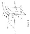
- the inventionprovides an electrical coupling system (“CS”) that allows the closing of an electrical circuit between two bodies, each with a surface that contains a conductive area.
- the CSprovides three degrees of freedom between the two surfaces.
- the first degreecomprises a linear movement along an X axis of an XY plane that is essentially co-planar to the larger of the bodies.
- the third degreecomprises a rotation around a Z axis that is perpendicular to the XY plane
- free positioning contactsmay include telescopic action in the Z axis direction (not shown).
- FIG. 1shows a simplified perspective view of a coupling system 10 comprising conductive area 12 which forms part of a charging or base unit (not shown) which is typically stationary.
- the CS 10also includes a second conductive area 14 which is part of an adapter unit (not shown). Also shown for orientation, is the above mentioned coordinate system comprising the x y plane and the Z axis perpendicular thereto.
- Electrical lead wires 16 and 18electrically connect the conductive areas 12 , 14 , respectively to the base unit and the adaptor unit, respectively.
- the conductive areas 12 , 14may either be attached to the base unit and the adaptor unit, respectively, or, in a preferred case, integrated with the base unit and the adaptor unit, respectively. This allows a power circuit between the base unit and the adaptor unit to be closed, without requiring alignment, as is required by conventional connectors, power charging cradles, etc.
- the CS 10may be used to provide power to notebook computers or other mobile devices by allowing the mobile devices to be placed freely on an energizing desktop or other surface which forms part of the base unit.
- the desktop or other surfaceforms the conductive area 12 of the CS 10 and a bottom of the mobile device acts as the conductive area 14 .
- a power supplyis connected to the conductive area 12 of the desk or surface (such as a desk pad, writing pad, etc.) and can close an electrical circuit with the conductive area 14 of the mobile device placed thereupon, thus allowing e.g. a charging or power circuit of the mobile device to be energized independently of an XY, or angular position of the mobile device on the desk top or other surface.
- the relative positioncan be expressed as a tuple of three numbers [X, Y, G] called “relative placement” or “placement” in short.
- the X and Y valuesdenote the linear displacement between the centers of the conductive areas 12 , 14 relative to the XY coordinate system.
- the G valuedenotes the relative radial angle in degrees between the conductive areas 12 , 14 , as projected onto the XY plane with some arbitrary relative rotation considered to have a rotation of zero degrees.
- a placementis said to be “supported” or “active” if a closed electrical circuit can be formed between the base unit and the adaptor unit through electrical contacts on or adjacent conductive areas 12 , 14 , respectively.
- a set of active placementsforms a continuous range without gaps. In other words, when the conductive area 14 rests on the conductive area 12 , a placement is guaranteed to be active regardless of the relative position of the conductive area 14 and the conductive area 12 .
- FIG. 2 of the drawingsshows a simplified view of an electrical connection between an adaptor unit and a base unit.
- the base unitcomprises conductive area 14 which includes at least two electrical contacts B 1 and B 2 that are electrically connected via electrical lead wires 20 to a power source 22 .
- the adaptor unitincludes at least two electrical contacts A 1 and A 2 that are electrically connected via electrical lead wires 24 to a circuit of the mobile device, for example a power or charging circuit, which is depicted, in simplified form, as electrical load 26 .
- a number, size, shape, dimension, spacing, and other spatial configuration aspects of the electrical contacts of the conductive surfaces 12 and 14are such that for each placement that is in the active range, there is at least one pair of contacts B 1 and B 2 of the base unit, and at least one pair of contacts A 1 and A 2 of the adaptor unit that satisfy the following conditions:
- a two wire electrical circuitcan be formed between the base unit and the adaptor units using contacts A 1 -B 1 as one lead and contact A 1 -B 2 as the other lead.
- more than two contacts (for example three contacts) of the base limitmay make contact with corresponding contacts of the adaptor unit to enable multi-phase power transmission between the base unit and the adaptor unit.
- a sensing circuitdetects a signal that is asserted by the adaptor unit contacts when they come into contact with the base unit contacts. The sensing circuit uses this information to activate the base unit contacts that are touched by the adaptor unit contacts. In other cases, the current can be redirected to the contacts by sensing the relative position of the conductive surfaces 12 and 14 . In other cases, the base unit can switch power to a sequence of pairs of base unit contacts until it senses that the circuit is closed with the mobile device. In other cases, the current routing can be done by mechanical switches that are activated by the conductive areas 12 , 14 based on their relative positions.
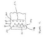
- FIG. 3 of the drawingsshows an example of a CS implementation for a notebook computer.
- the adaptor unitincludes an electrical load 26 that is electrically connected to two electrical contacts B 1 and B 2 .
- the conductive area 12 of the base unitincludes a plurality of circular electrical contacts 28 disposed in a rectangular array. Of these, electrical contacts 28 , contacts marked A 1 and A 2 are active in a sense that they receive power from the power supply 22 . It will be appreciated that the plurality of electrical contacts 28 allow for a wide range of movement in the X and Y directions and a 360° freedom of rotation around the Z axis for which placement of the electrical contacts is still active.
- the conductive area 12 of the base unitmay be defined by a top surface of a desktop, whereas the conductive area 14 of the adaptor unit may be built into a notebook computer with the contacts A 1 and A 2 mounted on a bottom surface of the notebook computer. In some cases the contacts A 1 and A 2 may be built into the notebook computer itself. In other cases, the contacts A 1 and A 2 may be part of an adaptor pad with conductive areas 12 .
- the adaptor padmay be attached to an underside of the notebook computer using an electrical wire lead that can be connected directly to a charging port of the notebook computer.
- the contacts 28are arranged as an array of circles of radius R with a horizontal and vertical spacing D between adjacent circles.
- the adaptor contacts A 1 , A 2 in this exampleeach comprises a circle of radius (R+D/2) ⁇ square root over (2) ⁇ and with at least a spacing greater than 2R.
- the base unitmay comprise electrical contacts arranged in a honeycomb pattern with interleaving non-conductive areas.
- the base contactsmay be linear and be disposed in a linear array.
- load 26symbolizes the electrical aspects of the notebook computer and, the power source 22 indicates a power supply. It will be appreciated by one skilled in the art that the load 26 and the power source 22 may in reality be quite complex.
- FIG. 4shows a case of a CS which does not require dynamic power routing or switching to the base contacts.
- the electrical contacts of the base(hereinafter referred to as the “base contacts”) B 1 and B 2 are in the form of the form of two rectangular pads 30 .
- the electrical contacts of the adaptor unit A 1 and A 2(hereinafter referred to as “adaptor contacts”) are in the form of two circular contact pads 32 .
- the arrangement shown in FIG. 3allows limited linear movement along the X and Y axes and limited rotational movement about the Z axis.
- the example of FIG. 4does not require dynamic power switching to the base contacts.
- movement along the X and Y axesis limited in the sense that an adaptor contacts 32 must always make contact with a base contact 30 .
- movement along the X axiscan occur until the adaptor contacts 32 reach the left edge of the base contacts 30 .
- rotation around the Z axisis limited in the sense that the adaptor contacts 32 must always make contact with the base contacts 30 .
- rotation along the Z axisis permitted as long as adaptor contacts 32 make contact with base contacts 30 .
- base contacts B 1 and B 2are not energized.
- a sensing unit in the base unitdetects the load and switches power to the contacts B 1 and B 2 based on information and properties of the load.
- the poweris of a predefined voltage and polarity, or frequency.
- the sensing unitmay sense various parameters such as operational status, identification, and power requirements from the load and perform authentication, authorization and compatibility checks before providing power to contacts B 1 and B 2 using the required voltage and polarity.
- the base or charging unitmay include a surface with a plurality of exposed contacts and may be configured to supply power to multiple loads, each connected to a further set of contacts and having different voltage characteristics.
- the charging unitwill provide protection against short circuits and overloads when contacts of the charging unit are connected, thus providing shock protection when exposed contacts of the charging unit are touched when an electrical load is not present.
- FIG. 5 of the drawingsshows a block diagram of one case of a base or charging unit of the present invention.
- the charging unitincludes a power supply 36 which is electrically connected via power input lines 38 to a power source and via power output lines 40 to electrical contacts 42 to 48 .
- electrical load 50which represents, for example electrical circuitry of a notebook computer, is electrically connected via electrical lead lines 52 to contacts 44 and 46 .
- the power supply 36receives power from a standard household current supply, but in some cases may also use other sources, such as generators, solar panels, batteries, fuel cells, etc. each separately, or in any combination.
- contacts of a power supplygenerally provide voltage in a preset voltage, frequency and polarity, independently of an actual load 50 attached to the power supply 36 .
- the power supply 36detects when, where, and how electrical load 50 is connected to the power contacts 42 - 48 and may sense information such as identification, product type, manufacturer, polarity power requirements, and other parameters and properties of the load and the connection type required. The base unit uses this information to connect the power supply 36 to the electrical load 50 .
- a power supplymay be adapted in terms of voltage, polarity and frequency to the needs of a specific electrical load, thus improving safety by avoiding exposed power connectors when no load is attached, and also providing the ability to power a plurality of electrical loads at the same time, each connected to an arbitrary set of contacts and receiving a different voltage.
- the exchange and negotiation of information between the electrical load 50 and the power supply 36is symbolized by arrows 54 and 56 in FIG. 5 of the drawings.
- arrow 54indicates that identification and status information associated with load 50 is supplied to a sensing circuit (not shown) of power supply 36 which ensures that the correct voltage, polarity and frequency of power is supplied to electrical contacts 44 and 46 .
- FIG. 6 of the drawingsa block diagram of a particular instance 60 of a system for supplying power described above is shown.
- the system 60may be used to deliver power to a multitude of power contacts, however, for purposes of simplicity, only two power contacts C 1 and C 2 are shown. Thus, it must be borne in mind that more contacts may be served by the power supply system 60 .
- the power supply system 60includes a voltage regulator 62 connected via electrical lines 64 to a current supply which may be a household current supply or any of the other sources mentioned above.
- a sensing unit 66is connected via a voltage control line 68 to the voltage regulator 62 and via sensing lines 72 and 74 to power contacts C 1 and C 2 , respectively.
- the contacts C 1 and C 2are electrically connected to a mobile device, for example, a notebook computer 76 which includes an electrical load 78 and an identification load 80 .
- the sensing unit 66senses the identification load 80 and in particular information such as identification, product type, manufacturer, polarity power requirements and other parameters and properties associated with the electrical load 78 .
- the power supply arrangement 60generally comprises more than just the power contacts C 1 and C 2 and thus, during a first stage, the sensing unit 66 scans for the presence of more than one electrical load 78 connected to the power contacts of the power supply 60 . After scanning, the sensing unit 66 sends a switch control signal 84 to the switching arrangement 82 to open and close the necessary switches in order to supply power to only those power contacts that have electrical loads connected thereto.
- the switches used during scanning for the presence of an electrical loadmay be combined or may be separate from polarity and voltage switches of the switching arrangement 82 . Further, advanced semiconductors may be used instead of simple mechanical or relay type switches which are indicated in FIG. 6 for the sake of simplicity.
- the sensing unit 66detects the unique identifier (ID) (represented as identification load 80 ) of the load 78 through the sensing lines 72 and 74 and uses this ID to determine the voltage, current and polarity requirements of the load 78 . If the voltage and the current requirements are in the range supported by the power supply, the sensing unit 66 sends a signal to the switch arrangement 82 to power a source in the right polarity and also sends a signal to voltage regulator 62 to set the required voltage.
- IDunique identifier
- the sensingis done by applying a minimal, non-destructive sensing voltage or pattern, and observing responses of the identification load or element 80 .
- the ID element 80may be a simple resistor, that is read with a very low voltage below the activation of the normally non-linear response of the electrical or device load 78 .
- the ID element 80may be a diode, or a resistor and a diode combination, or any passive or active circuit, including conductors and capacitors etc. that can be used to convey the presence and parameters associated with load 78 .
- RFIDradio frequency Identity
- a digital IDmay be used, and read, with a voltage that is below the active region of the load, or in some cases the adaptor unit may have intelligence to disconnect the load 78 until it establishes a connection or gets power from the base unit. This may be useful, for example, for resistive loads.
- the sensing unit 66detects that the device bearing the ID element 80 is not connected to the power supply and turns off the switching arrangement 82 , thereby disconnecting the power from the contact C 1 and C 2 .
- the base unitmay disconnect based on a sensing of a mobile device current usage passage.
- FIG. 7shows a block diagram of a power provisioning system 90 having multiple contacts C 1 , C 2 , C 3 , C 4 and C 5 .
- the contacts C 1 -C 5are used to provide power to electrical loads 78 which are denoted as Load 1 and Load 2 in FIG. 7 .
- ID elements 80denoted as ID 1 and ID 2 respectively, provide identification information associated with Load 1 , and Load 2 respectively, as described above.
- Sensing unit 66controls a switching arrangement 82 to provide power at two predefined voltage levels (V 1 and V 2 ) to the loads 78 , while automatically adapting the power polarity for each load 78 .
- the sensing unit 66detects that identification element ID 1 is connected between power contacts C 1 (+) and C 3 ( ⁇ ), the sensing unit 66 activates the switches of contacts C 1 and C 2 to connect C 1 to the (+) side of power source V 1 and connects C 2 of the ( ⁇ ) side of the power source V 1 .
- the Load 2is connected to V 2 in the correct polarity through C 2 and C 6 .
- the sensing unit 66may typically comprise a microcontroller and adaptation circuitry, including resistors, diodes, capacitors and possibly active components as well. Naturally, there will be a power supply to the sensing unit 66 itself, which has not been shown in FIG. 7 , so as not to obscure aspects of the present invention.
- control switchesmay be solid state or relays.
- the ID elementsmay not only be used to provide identification information, but may actually control power flow to a device (not shown) to which it is connected by means of a switch (not shown). In these cases, the ID elements may include verification of voltage and current type (AC, DC etc.) and other auxiliary functions.
- the adaptor unitmay receive commands from the base unit (e.g. turn power on, set ID unique to the pad, etc.) Further, the adaptor unit may be integrated with the power management of the device to which it is connected (e.g. for retrieving information about battery state, CPU usage, etc.).
- the above described power provisioning systemmay be combined with other elements to form a complete system that allows a user more freedom when using a notebook computer, for example, at a desk or similar environment, such as a home office, a hotel, an office, or even at a kiosk at an airport or other public place.
- FIG. 8 of the drawingsshows a desk 100 on which is placed a desk mat 102 .
- the desk mat 102includes a conductive area 12 with electrical contacts as described above.
- the desk mat 102may be integrated into the desk 100 .
- the desk mat 102includes a conductive plastic that may be applied in a thin layer on top of a metallic conductor interleaved with non-conductive material and surrounded by conductive plastic and metal.
- color metallic areasmay be silk screened onto mat 102 , leaving sufficient openings for contacts.
- acidic etchings into a metal substratemay create openings to deposit colored resins, in a process similar to the anodizing of aluminum.
- chrome-plated or nickel-finished round metal contactsmay be embedded in a rubber mat. All of the above approaches can be used to make a desk mat product that is visually appealing to consumers, and functions as a base for a charging or power unit as described above.
- a cabling system 104which is hidden within the desk 100 connects to a power supply 106 that contains both the power source itself and the sensing and switching arrangement described above.
- a power cord 108 ending in a power connector 110plugs into a regular household AC outlet, of the type available in homes and offices.
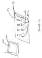
- FIG. 9shows one case in which an adaptor unit or piece 118 is releasably secured to a notebook computer 112 .
- the notebook computer 112is shown from a lower rear-end and includes a base section 114 and a lid section 116 . As can be seen in FIG. 9 of the drawings, the notebook computer 112 is slightly opened with the lid section 116 spaced from and hingedly connected to the base section 114 .
- the adaptor piece 118is attached to an underside of the base section 114 using, for example, hook-and-pile fasteners, mounting tape, or any other suitable fastening arrangement including but not limited to screws, bolts, glue, cement, snaps etc.
- the adaptor unit 118has, in this example, three separate areas 120 , 122 and 124 as can be seen.
- the areas 120 and 124may be conductive surfaces and the area 122 may be an insulator.
- a cable 126is used to connect the adaptor unit 118 to the notebook computer 112 via a regular power supply port of the notebook computer 112 .
- a wireless network card 128protrudes from a port of the notebook computer 112 .
- the adaptor unit 118may be integrally formed with the notebook computer, or in other cases, it may more specifically integrated with a battery unit or an enclosure for a battery unit, hence requiring a special cable or attachment.
- a convenient recepticlemay be offered, so that the user does not have to unplug the adaptor unit in case of using a regular charger with a base.
- the adaptor unitmay be electrically disconnected, so as to avoid hazards by exposing live contacts.
- FIG. 10shows a schematic drawing in which the notebook computer 112 is placed on a conductive mat 102 of a desk 100 .
- Each of the components 100 , 102 and 112have been described with reference to FIGS. 8 and 9 respectively.
- notebook computer 112is placed at an odd angle, to exemplify that such a device may, according to the novel art of this disclosure, be placed in any position on conductive mat 102 , thus allowing for notebook computer 112 to be charged or powered while the notebook is in use, without having to plug in any cable or carry any power supplies.
- contacts 120 , 122 and 124 of the adaptor unit 118may be round as opposed to being square and may have dimensions that match those of the notebook base section 114 , rather than being scaled to a functional minimal size.
- adaptor unit 118may connect to a docking connector for notebook computer 112 , as opposed to using a power cord arrangement.
- adaptor unit 118may be integrated into the standard enclosure of a notebook, thus eliminating a need for a separate, add on device.
- Desk mat 102may also have many variations. In one case desk mat 102 may be used in conjunction with a standard power supply provided by a notebook manufacturer and may contain by itself only the sensing and switching functionality, rather than the full power supply.
- the systemmay be used to transmit data over the established electrical connections, as opposed to just power. This may be achieved either by using additional contacts, or by modulating signals onto the existing power leads and adding a filter (i.e. inductor/capacitor) to separate DC supply from high speed data signals such as Ethernet signals etc.
- a filteri.e. inductor/capacitor
- an Ethernet portmay be offered in both a desk mat 102 and a cable on adaptor unit 118 .
- Other network standards besides Ethernetmay also be supported, as desired or required.
- wireless methodsmay be used for the data transmissions. These methods include but are not limited to optical methods including infrared (IR), inductive coupling, capacitive coupling, or radio frequency with or without modulation.
- Some casesmay include virtual docking connections or regular local area network connections, or both.
- a mat 102may be integrated into the desk 100 .
- the matmay be a foldable or rollable mat reduced in size for easy portability, for the convenience of travelers.
- input devicesmay be integrated into the base charging unit, for example a tablet or a large touch pad, the pad surface may be mouse friendly (both to mechanical and optical mice) or it may be used to power semi-mobile devices such as desk lamps, electrical staplers, etc.
- the desk mat 102may be of an anti-static material (thus making it safer than using no mat at all).
- extensionsmay be offered as modules, including making the mat area of the charging power device modular (cutting to order, tiles etc.).
- the base unitprovides a standard power and each device/adaptor converts it to the level needed by its respective device.
- the devicealso makes some decisions on power switching (for example is this space safe to use
- the contact surfacemay be made like a fabric (printed or woven), and applied to walls in offices, schools, homes, stores etc.
- the sensing or interrogation before releasing powermay be used in existing building wiring, controlling outlets. Thus, only an authorized device can draw power. This may have important benefits such as improving safety (e.g. for children), or for security against power theft in public or semipublic places, or avoiding overload to a back-up network. In a hospital, for instance, non-essential units accidentally plugged in to an emergency power system would not work without an override.
- the base unitmay do power allocation and management, e.g. between multiple devices being powered at the same time. The functionality of the system can be divided in many ways between the pad surface and the device.
- the systemcan also provide for an adapter/device to have more than two contacts and it can do smart power routing/conversion as well.
- the surface contacts or some of themcan be energized or grounded all the time (e.g. the interleaving geometry).
- the surfacemay have only one pair of contacts.
- ‘handshaking’does not require bi-directional communication or communication at all.
- Some implementationcan use for example simple analog sensing of resistance or diode.
- sensingmay entail multiple steps, such as 1. check for diode 2. check resistor and 3. check ID digitally. Each of the steps may use different voltages, and in some cases only one, or two or three may be done. Further, tests may also include DC, AC and modulated probing signals.
- FIG. 11 of the drawingsshows a track system comprising interleaved positive and negative tracks.
- the positive tracksare indicated by reference numerals 130 , 132 and 134
- the negative tracksare indicated by reference numerals 136 and 138 .
- Each trackincludes a number of longitudinally spaced projections which stand proud of the track and which are indicated, generally by reference numeral 140 .
- the projectionsmay take a form of nails, bolts, etc. which stand proud of the tracks themselves.
- FIG. 12 of the drawingsshows a top plan view of a portion of FIG. 11 show only tracks 130 , 132 and 136 .
- the track systemis integrated into a base pad 144 .
- the circular areas in FIG. 12represent the rising conductors or projections 140 which are also known as feed points in (FPs) which extend into an out of the plane of the page in both directions, depending on a size that is required.
- FPsfeed points in
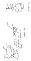
- FIG. 13 of the drawingsshows the base pad 144 which is in contact with an overlying adaptor pad 150 (hereinafter adaptor pad) comprising three circular electrical contacts 152 , 154 and 156 .
- the positive FPsare denoted as 140 A and the negative FPs as 140 B.
- Each electrical contact 152 , 154 and 156is separated from each other and may be used to feed a selection logic that determines which contact 152 - 156 has been connected to a positive FP 140 A and which contact has been connected to a negative FP 140 B.
- a higher number of contactssuch as four or more may be required to guarantee at least one contact to a positive FP 140 A and one contact to a negative FP 140 B, depending on both a geometry of the pad 144 and the adaptor pad 150 , as well as a geometry of the contacts 152 to 156 and the FPs 140 .
- only three contacts 152 to 156have been shown.
- the words positive and negativeare to be seen in the broadest terms as simply representing conduits for power, since in some cases, rather than DC, AC may be used, or pluses, or power in conjunction with data etc.
- the simplest way to achieve correct connectivityis to use a bridge rectifier to extract the voltage from the FPs 140 and then to use that voltage to drive circuitry (not shown) between adaptor pad 150 and a device (not shown), such as a notebook computer.
- the circuitrythen, using low drop switches (i.e. bipolar solid state switches in parallel to the bridge rectifier), connects the actual contacts of the adaptor pad 150 to the conductors of the notebook charger connector (details not shown).
- the adaptor pad 150 and their contacts 152 to 156must be such that they cannot short between positive and negative FPs, on the one hand, and that independently of the positioning on the surface, must always be connected to at least one positive and one negative FP.
- a complete railmay surface and depending on the dimensions and distances, the dimensions and distances as well as the geometry of the adaptor pad 150 may change.
- a linear arraybe better, or a T-shaped, X-shaped, a honeycomb cluster of contacts, or other suitable multi-port connection may be used instead of a adaptor pad 150 having a contact geometry as soon in FIG. 13 .
- a diamond shaped adaptor pad 150using four rather than just three contacts in conjunctions with an interleaving field of cylindrical FPs 140 as shown in FIG. 13 , may be used.
- the FPs 140may in some cases be formed into diamond shapes, covering almost all of the surface of the pad 144 , with very tiny gaps for insulation, or may be formed in a honeycomb pattern. In other cases, the FPs 140 may resemble round dots, as shown in FIG. 13 and may be arranged in the geometry shown in FIG. 13 , or any other suitable geometry. In some cases, the FPs 140 may comprise spherical or cylindrical projections with or without mitering, or pokes, etc. As noted above, more than three or four electrical contacts may be required to guarantee contact to a pair of FPs 140 of with opposite plurality.
- Suitable geometries for the FPs 140may be obtained by modeling their connectivity using a mathematical model and a computer. In some cases, the design of the FPs 140 on pad 144 may be driven by industrial design concepts.
- the adaptor pad 150it is preferable to arrange the adaptor pad 150 across the whole surface area of the mobile device, rather than across only a localized portion, thus allowing the weight of the mobile device to be distributed across all contacts 152 to 156 , ensuring a better electrical contact, as opposed to having all contacts of the adaptor pad 150 in one corner, which might result in some of them lifting off (unless they are spring loaded or the pad is pivotally mounted).
- the contacts 152 to 156may be integrated into an enclosure of the mobile device itself, with internal connections.
- powermay always be on the FPs 140 thus not requiring any sensing to be performed. In other cases, only basic short circuit protection may be provided.
- FIG. 14shows another example of a pad 144 whose microstructure has been sectioned into rectangular elements 158 .
- the positive FPs 140 A of each section of 158could be connected separately through a cable 160 to an adaptive power supply 162 and the negative FPs 140 B throughout the whole pad could stay connected to the power supply 162 so that it is always on.
- the pad 144once a mobile device is placed on the pad 144 , only that section containing the mobile device may be activated. Thus, different sections of the pad 144 could have different voltages, allowing the mobile device not to require a regulator or an adaptor unit.
- a usermay place a mobile phone and notebook computer, an a PDA all onto surface 144 , and the adaptive power supply would, after identifying each device, turn on either a standard voltage or a voltage specific to each device, depending on whether the devices have voltage adaptors themselves or only have identification switching devices.
- FIG. 15 of the drawingsshows a pad 170 of either conductive or non-conductive material, having a thickness D.
- an inductorindicated generally by reference numeral 172 which is connected to longitudinal and transverse arms 174 and 176 respectively.
- a drive mechanismcomprising a screw fitted shank 178 and a motor 180 can be operated to displace arm 174 in a direction parallel to transverse arm 176 .
- the arm 176is connected to a drive mechanism comprising a screw fitted shank 182 to a motor 184 which can be operated to displace the inductor 172 in a direction parallel to the arm 174 .
- FIG. 15 of the drawingsdepicts a drive mechanism comprising screw fitted shanks 178 and 182 coupled to electrical motors 180 and 184 respectively, it will be appreciated by one skilled in the art that other drive mechanisms are possible such as belt drives, scissor arms, etc.
- a notebook computer 186includes a matching inductor 188 that may contain some circuitry.
- a cable 190couples the inductor 188 to standard charging circuitry of the notebook computer 186 .
- the inductor 188may be integrated into the notebook 186 .
- the motors 180 and 184are activated, for example by a command such as pushing a button or by detection means such as weight detection or other detection means to detect the position of the notebook 186 on the pad 170 based on a location of the inductor 188 .
- a controllermay be embedded in the pad 170 , or may be part of a power supply (also not shown) for the pad 170 and is used to send data to a small controller/receiver unit (not shown). In other cases, the controller may be controlled by the notebook 186 .
- the controller aided by motors 180 and 184can detect an area (called a sweet spot port) where optimal or near-optimal coupling between the inductor 172 and inductor 188 may be achieved, which then provides an indication of the relative position of inductor 188 and hence notebook computer 186 on the pad 170 .
- the inductor 188may send out a homing signal that may be used to track a location of the notebook computer 186 on the pad 170 .
- inductor 172may send out a ping signal and listen for a resulting echo response from inductor 188 .
- other sensor type or optical detectioncan also be used to assist in searching the position of inductor 188 relative to the pad 170 .
- small step wise incrementsallow for more accurate positioning of the inductor 188 relative to the inductor 172 , thus allowing power to be increased once optimal magnetic coupling between inductors 172 and 188 is achieved. If a user were to move notebook computer 186 , then the magnetic coupling quality would fall, which could be observed by the adaptive power supply resulting in shutting off power and initiating a new search sequence to align inductors 188 and 172 for the purposes of charging notebook computer 186 .
- FIG. 16 of the drawingsanother configuration can be seen whereby a notebook computer 200 is inductively coupled to a charging pad 192 for the purposes of charging the notebook computer 200 .
- the charging pad 192includes a plurality of inductors 194 which are distributed through a substrate of the charging pad 192 which may be conductive or non-conductive.
- Each of the conductors 194is connected to a controller 196 which, in turn is connected to a power supply (not shown) via an electrical lead line 198 .
- the notebook computer 200includes an inductor in a form of a receiver coil 202 which is dimensioned such that when the notebook computer 200 is placed on a surface of the charging pad 192 , the inductor 202 encloses several inductors 194 of the charging pad 192 .
- the inductors 194may be provided with electronic switching whereby power to the inductors 194 is switched on by controller 196 . However, in other embodiments, no electronic switching of the inductors 194 is provided.
- the inductors 194 and the inductor coil 202power can then be selectively turned on to one or more of the inductors 194 , thereby to improve coupling between the inductor coil 202 and the inductors 194 which then function as an emitting coil.
- FIGS. 17A to 17C of the drawingsshows yet another approach for a coupling system.
- a pad 204which either may be conductive or non-conductive, although non-conductive is preferred, is divided into an array of electrodes 206 .
- a notebook computer indicated generally by reference numeral 208(see FIG. 17B ) has two electrodes 210 and 212 , which are connected to a power receiving unit 214 which in turn is connected via a cable 216 to a power adaptor plug of the notebook computer 208 .
- FIG. 17Bshows yet another approach for a coupling system.
- FIG. 17a pad 204 , which either may be conductive or non-conductive, although non-conductive is preferred, is divided into an array of electrodes 206 .
- a notebook computer indicated generally by reference numeral 208has two electrodes 210 and 212 , which are connected to a power receiving unit 214 which in turn is connected via a cable 216 to a power adaptor plug of the notebook computer 208 .
- FIG. 17Cshows that, based on a determination of a position of notebook computer 208 on charging pad 204 , electrodes 206 A and 206 B are selected from available electrodes 204 to form a capacitive transformer with notebook electrodes 210 and 212 . Power is fed into power receiving unit 214 and hence to notebook computer 208 via the cable 216 .
- the charging pad 204may be a combination wherein one “wire” is conductive (e.g. ground) and the other is capacitive.
- a pad 220which may be conductive or non-conductive is partitioned into rectangular sections 222 , each of which contains a sensor element 224 .
- the sensor element 224may be a photosensor.
- the sensor elements 224may simply comprises mechanical pressure switches, or piezo-electric pressure or weight sensors, etc.
- a position of a mobile device on the charging pad 220may be determined using information such as a weight and footprint of the mobile device. In some cases even a device ID for the mobile device may be used.
- the piezo-electric sensorsmay pick up ultrasonic signals emitted by a notebook computer or, in other cases the sensors may ping the notebook computer, which will then respond with an echo giving information about its position and its type.
- a camera indicated generally by reference 230may be used to take a picture of the pad 220 and to monitor (“see”) a device's position on the pad 220 .
- image recognition means associated with the camera 230may recognize a model and type of a mobile device, as well as its orientation and may then instruct an adaptive power supply or one of the non-conductive systems described above, to activate the power accordingly.
- a voice recognition system indicated generally by reference numeral 240may include a microphone 242 connected to it.
- a usermay simply say, for example “please charge my SonyTM notebook computer” and accordingly, the voice recognition system 240 would instruct the adaptor power supply or a non-conductive charging pad to turn on power.
- radio frequency link with a networksuch as an 802.11 ⁇ type network or a GPS network or any other network, may be used to locate (triangulate) the position of a mobile device and determine whether it is situated on a pad and thereafter to activate the pad (not shown) accordingly.
- a buttonmay be provided on a charging pad itself or on a mobile device to be charged that when activated, for example by pushing, initiates charging, rather than automatic initiation of charging. Such a manual initiation of charging would avoid unintentional charging cycles.
- a pad deploying a conductive surface with openingmay be placed above another solid conducting surface, separated by an insulating layer with slightly smaller openings (not shown).
- Ball-like contactsmay be spring loaded and may protrude from an undersurface of a mobile device, such that some of these balls will “land” in the holes and connect to a lower plane carrying one polarity, the others resting on an upper plane, connected to a top layer carrying another polarity.
- currentmay be redirected to proper contacts by sensing a pressure exerted by the mobile device on a base unit. Once a mobile is placed on top a surface of the base unit, pressure on the surface determines a location of the mobile device and routes power to the appropriate location.
- currentmay be redirected to proper contacts by using optical senses.
- Certain senses embedded in a base unitwill detect an optical signal, such as an infrared signal generated by an adaptor unit. Based on a formula dependent on the optical signal, the base unit may then redirect power to the proper contacts.
- the optical signalmay be generated at or away from the base unit and thereafter receive the adaptor unit.
- the adaptor unitmay be connected, attached, or integrated into a side of a mobile device.
- the adaptor unitwould include contacts that connect to corresponding contacts to a base unit.
- the adaptor unitmay be attached to a prop of the mobile device or to a screen of the mobile device. In such cases, when the lap top screen is fully open power would then be transferred to contacts on a base unit to the adaptor unit on the mobile device.
Landscapes
- Charge And Discharge Circuits For Batteries Or The Like (AREA)
Abstract
Description
- (a) contactor B1 of the base unit touches A1 of the adaptor unit;
- (b) contactor B2 of the base unit touches contactor A2 of the adaptor unit; and
- (c) the electrical contact of the base unit and the adaptor unit do not form a short circuit between electrical contacts B1 and B2.
Claims (15)
Priority Applications (4)
| Application Number | Priority Date | Filing Date | Title |
|---|---|---|---|
| US10/211,224US7392068B2 (en) | 2002-03-01 | 2002-08-01 | Alternative wirefree mobile device power supply method and system with free positioning |
| AU2003213627AAU2003213627A1 (en) | 2002-03-01 | 2003-02-27 | Power and network connection arrangements for mobile devices |
| PCT/US2003/006166WO2003075415A1 (en) | 2002-03-01 | 2003-02-27 | Power and network connection arrangements for mobile devices |
| TW092104398ATW200402913A (en) | 2002-03-01 | 2003-03-03 | Power and network connection arrangments for mobile devices |
Applications Claiming Priority (6)
| Application Number | Priority Date | Filing Date | Title |
|---|---|---|---|
| US36163102P | 2002-03-01 | 2002-03-01 | |
| US36160202P | 2002-03-01 | 2002-03-01 | |
| US36162602P | 2002-03-01 | 2002-03-01 | |
| US36559102P | 2002-03-18 | 2002-03-18 | |
| US36610102P | 2002-03-19 | 2002-03-19 | |
| US10/211,224US7392068B2 (en) | 2002-03-01 | 2002-08-01 | Alternative wirefree mobile device power supply method and system with free positioning |
Publications (2)
| Publication Number | Publication Date |
|---|---|
| US20040082369A1 US20040082369A1 (en) | 2004-04-29 |
| US7392068B2true US7392068B2 (en) | 2008-06-24 |
Family
ID=27792372
Family Applications (1)
| Application Number | Title | Priority Date | Filing Date |
|---|---|---|---|
| US10/211,224Expired - Fee RelatedUS7392068B2 (en) | 2002-03-01 | 2002-08-01 | Alternative wirefree mobile device power supply method and system with free positioning |
Country Status (4)
| Country | Link |
|---|---|
| US (1) | US7392068B2 (en) |
| AU (1) | AU2003213627A1 (en) |
| TW (1) | TW200402913A (en) |
| WO (1) | WO2003075415A1 (en) |
Cited By (266)
| Publication number | Priority date | Publication date | Assignee | Title |
|---|---|---|---|---|
| US20060014565A1 (en)* | 2004-07-19 | 2006-01-19 | Chien-Tsung Chen | Multi-output connector capable of receiving data wirelessly |
| US20060205381A1 (en)* | 2002-12-16 | 2006-09-14 | Beart Pilgrim G | Adapting portable electrical devices to receive power wirelessly |
| US20070194526A1 (en)* | 2002-12-10 | 2007-08-23 | Mitch Randall | System and method for providing power to an electronic device |
| US20080200119A1 (en)* | 2007-02-16 | 2008-08-21 | Seiko Epson Corporation | Power reception control device, power transmission control device, non-contact power transmission system, power reception device, power transmission device, and electronic instrument |
| US20090098750A1 (en)* | 2002-12-10 | 2009-04-16 | Mitch Randall | Reliable contact and safe system and method for providing power to an electronic device |
| US20090177908A1 (en)* | 2008-01-07 | 2009-07-09 | Access Business Group International Llc | Wireless power adapter for computer |
| US20090278494A1 (en)* | 2008-03-03 | 2009-11-12 | Mitch Randall | Universal electrical interface for providing power to mobile devices |
| US20100070219A1 (en)* | 2007-03-22 | 2010-03-18 | Powermat Ltd | Efficiency monitor for inductive power transmission |
| US20100194336A1 (en)* | 2007-10-18 | 2010-08-05 | Powermat Ltd. | Inductively chargeable audio devices |
| US20100219183A1 (en)* | 2007-11-19 | 2010-09-02 | Powermat Ltd. | System for inductive power provision within a bounding surface |
| US20100219693A1 (en)* | 2007-11-19 | 2010-09-02 | Powermat Ltd. | System for inductive power provision in wet environments |
| US20100219697A1 (en)* | 2007-09-25 | 2010-09-02 | Powermat Ltd. | Adjustable inductive power transmission platform |
| US20100290215A1 (en)* | 2009-05-12 | 2010-11-18 | Kimball International, Inc. | Furniture with wireless power |
| US7952324B2 (en) | 2002-05-13 | 2011-05-31 | Access Business Group International Llc | Contact-less power transfer |
| US20110157137A1 (en)* | 2008-07-08 | 2011-06-30 | Powermat Ltd. | Encapsulated pixels for display device |
| US20110189954A1 (en)* | 2003-02-04 | 2011-08-04 | Access Business Group International Llc | Adaptive inductive power supply with communication |
| US20110210617A1 (en)* | 2009-08-28 | 2011-09-01 | Pure Energy Solutions, Inc. | Power transmission across a substantially planar interface by magnetic induction and geometrically-complimentary magnetic field structures |
| US8188619B2 (en) | 2008-07-02 | 2012-05-29 | Powermat Technologies Ltd | Non resonant inductive power transmission system and method |
| US8320143B2 (en) | 2008-04-15 | 2012-11-27 | Powermat Technologies, Ltd. | Bridge synchronous rectifier |
| US20120328094A1 (en)* | 2005-10-14 | 2012-12-27 | Research In Motion Limited | Interface and communication protocol for a mobile device with a smart battery |
| US20130026973A1 (en)* | 2011-07-26 | 2013-01-31 | Gogoro, Inc. | Apparatus, method and article for authentication, security and control of power storage devices, such as batteries |
| US8554284B2 (en) | 2005-10-14 | 2013-10-08 | Blackberry Limited | Mobile device with a smart battery having a battery information profile corresponding to a communication standard |
| US8618695B2 (en) | 2008-06-02 | 2013-12-31 | Powermat Technologies, Ltd | Appliance mounted power outlets |
| US8629577B2 (en) | 2007-01-29 | 2014-01-14 | Powermat Technologies, Ltd | Pinless power coupling |
| US8639219B2 (en) | 2005-10-14 | 2014-01-28 | Blackberry Limited | Battery pack authentication for a mobile communication device |
| US20140194160A1 (en)* | 2013-01-04 | 2014-07-10 | Silicon Spread Corporation | Wireless charger circuit and method |
| US8862388B2 (en) | 2011-07-26 | 2014-10-14 | Gogoro, Inc. | Apparatus, method and article for providing locations of power storage device collection, charging and distribution machines |
| US8862304B2 (en) | 2011-07-26 | 2014-10-14 | Gogoro, Inc. | Apparatus, method and article for providing vehicle diagnostic data |
| US8878487B2 (en) | 2011-07-26 | 2014-11-04 | Gogoro, Inc. | Apparatus, method and article for providing to a user device information regarding availability of portable electrical energy storage devices at a portable electrical energy storage device collection, charging and distribution machine |
| US8981598B2 (en) | 2008-07-02 | 2015-03-17 | Powermat Technologies Ltd. | Energy efficient inductive power transmission system and method |
| US9035602B2 (en) | 2012-08-24 | 2015-05-19 | Silicon Spread Corporation | Wireless battery charger for mobile devices and method thereof |
| US9035501B2 (en) | 2008-03-17 | 2015-05-19 | Powermat Technologies, Ltd. | System and method for providing simple feedback signals indicating if more or less power is required during inductive power transmission |
| US9124121B2 (en) | 2008-09-23 | 2015-09-01 | Powermat Technologies, Ltd. | Combined antenna and inductive power receiver |
| US9124308B2 (en) | 2009-05-12 | 2015-09-01 | Kimball International, Inc. | Furniture with wireless power |
| US9124085B2 (en) | 2013-11-04 | 2015-09-01 | Gogoro Inc. | Apparatus, method and article for power storage device failure safety |
| US9123035B2 (en) | 2011-04-22 | 2015-09-01 | Angel A. Penilla | Electric vehicle (EV) range extending charge systems, distributed networks of charge kiosks, and charge locating mobile apps |
| US9129461B2 (en) | 2011-07-26 | 2015-09-08 | Gogoro Inc. | Apparatus, method and article for collection, charging and distributing power storage devices, such as batteries |
| DE102014007070A1 (en) | 2014-05-15 | 2015-11-19 | Bury Sp.Z.O.O | Charging station for an electrical device |
| US9216687B2 (en) | 2012-11-16 | 2015-12-22 | Gogoro Inc. | Apparatus, method and article for vehicle turn signals |
| US9275505B2 (en) | 2011-07-26 | 2016-03-01 | Gogoro Inc. | Apparatus, method and article for physical security of power storage devices in vehicles |
| US9276436B2 (en) | 2013-11-08 | 2016-03-01 | Silicon Spread Corporation | Wireless charger for mobile devices with flexible platform and method |
| US9331750B2 (en) | 2008-03-17 | 2016-05-03 | Powermat Technologies Ltd. | Wireless power receiver and host control interface thereof |
| US9337902B2 (en) | 2008-03-17 | 2016-05-10 | Powermat Technologies Ltd. | System and method for providing wireless power transfer functionality to an electrical device |
| US9390566B2 (en) | 2013-11-08 | 2016-07-12 | Gogoro Inc. | Apparatus, method and article for providing vehicle event data |
| US9407024B2 (en) | 2014-08-11 | 2016-08-02 | Gogoro Inc. | Multidirectional electrical connector, plug and system |
| US9424697B2 (en) | 2011-07-26 | 2016-08-23 | Gogoro Inc. | Apparatus, method and article for a power storage device compartment |
| US9438070B2 (en) | 2013-09-30 | 2016-09-06 | Norman R. Byrne | Articles with electrical charging surfaces |
| US9437058B2 (en) | 2011-07-26 | 2016-09-06 | Gogoro Inc. | Dynamically limiting vehicle operation for best effort economy |
| US9484751B2 (en) | 2013-09-30 | 2016-11-01 | Norman R. Byrne | Wireless power for portable articles |
| US9552682B2 (en) | 2011-07-26 | 2017-01-24 | Gogoro Inc. | Apparatus, method and article for redistributing power storage devices, such as batteries, between collection, charging and distribution machines |
| US9577461B2 (en) | 2014-04-16 | 2017-02-21 | International Business Machines Corporation | Multi axis vibration unit in device for vectored motion |
| US9597973B2 (en) | 2011-04-22 | 2017-03-21 | Angel A. Penilla | Carrier for exchangeable batteries for use by electric vehicles |
| USD789883S1 (en) | 2014-09-04 | 2017-06-20 | Gogoro Inc. | Collection, charging and distribution device for portable electrical energy storage devices |
| US9770996B2 (en) | 2013-08-06 | 2017-09-26 | Gogoro Inc. | Systems and methods for powering electric vehicles using a single or multiple power cells |
| US9787103B1 (en) | 2013-08-06 | 2017-10-10 | Energous Corporation | Systems and methods for wirelessly delivering power to electronic devices that are unable to communicate with a transmitter |
| US9793758B2 (en) | 2014-05-23 | 2017-10-17 | Energous Corporation | Enhanced transmitter using frequency control for wireless power transmission |
| US9800172B1 (en) | 2014-05-07 | 2017-10-24 | Energous Corporation | Integrated rectifier and boost converter for boosting voltage received from wireless power transmission waves |
| US9800080B2 (en) | 2013-05-10 | 2017-10-24 | Energous Corporation | Portable wireless charging pad |
| US9806564B2 (en) | 2014-05-07 | 2017-10-31 | Energous Corporation | Integrated rectifier and boost converter for wireless power transmission |
| US9812890B1 (en) | 2013-07-11 | 2017-11-07 | Energous Corporation | Portable wireless charging pad |
| US9819230B2 (en) | 2014-05-07 | 2017-11-14 | Energous Corporation | Enhanced receiver for wireless power transmission |
| US9824815B2 (en) | 2013-05-10 | 2017-11-21 | Energous Corporation | Wireless charging and powering of healthcare gadgets and sensors |
| US9825674B1 (en) | 2014-05-23 | 2017-11-21 | Energous Corporation | Enhanced transmitter that selects configurations of antenna elements for performing wireless power transmission and receiving functions |
| US9830753B2 (en) | 2011-07-26 | 2017-11-28 | Gogoro Inc. | Apparatus, method and article for reserving power storage devices at reserving power storage device collection, charging and distribution machines |
| US9831718B2 (en) | 2013-07-25 | 2017-11-28 | Energous Corporation | TV with integrated wireless power transmitter |
| US9837842B2 (en) | 2014-01-23 | 2017-12-05 | Gogoro Inc. | Systems and methods for utilizing an array of power storage devices, such as batteries |
| US9838083B2 (en) | 2014-07-21 | 2017-12-05 | Energous Corporation | Systems and methods for communication with remote management systems |
| US9843213B2 (en) | 2013-08-06 | 2017-12-12 | Energous Corporation | Social power sharing for mobile devices based on pocket-forming |
| US9843229B2 (en) | 2013-05-10 | 2017-12-12 | Energous Corporation | Wireless sound charging and powering of healthcare gadgets and sensors |
| US9843201B1 (en) | 2012-07-06 | 2017-12-12 | Energous Corporation | Wireless power transmitter that selects antenna sets for transmitting wireless power to a receiver based on location of the receiver, and methods of use thereof |
| US9847677B1 (en) | 2013-10-10 | 2017-12-19 | Energous Corporation | Wireless charging and powering of healthcare gadgets and sensors |
| US9847669B2 (en) | 2013-05-10 | 2017-12-19 | Energous Corporation | Laptop computer as a transmitter for wireless charging |
| US9847679B2 (en) | 2014-05-07 | 2017-12-19 | Energous Corporation | System and method for controlling communication between wireless power transmitter managers |
| US9853458B1 (en) | 2014-05-07 | 2017-12-26 | Energous Corporation | Systems and methods for device and power receiver pairing |
| US9853485B2 (en) | 2015-10-28 | 2017-12-26 | Energous Corporation | Antenna for wireless charging systems |
| US9853692B1 (en) | 2014-05-23 | 2017-12-26 | Energous Corporation | Systems and methods for wireless power transmission |
| US9859797B1 (en) | 2014-05-07 | 2018-01-02 | Energous Corporation | Synchronous rectifier design for wireless power receiver |
| US9859757B1 (en) | 2013-07-25 | 2018-01-02 | Energous Corporation | Antenna tile arrangements in electronic device enclosures |
| US9859756B2 (en) | 2012-07-06 | 2018-01-02 | Energous Corporation | Transmittersand methods for adjusting wireless power transmission based on information from receivers |
| US9859758B1 (en) | 2014-05-14 | 2018-01-02 | Energous Corporation | Transducer sound arrangement for pocket-forming |
| US9866279B2 (en) | 2013-05-10 | 2018-01-09 | Energous Corporation | Systems and methods for selecting which power transmitter should deliver wireless power to a receiving device in a wireless power delivery network |
| US9867062B1 (en) | 2014-07-21 | 2018-01-09 | Energous Corporation | System and methods for using a remote server to authorize a receiving device that has requested wireless power and to determine whether another receiving device should request wireless power in a wireless power transmission system |
| US9871398B1 (en) | 2013-07-01 | 2018-01-16 | Energous Corporation | Hybrid charging method for wireless power transmission based on pocket-forming |
| US9871387B1 (en) | 2015-09-16 | 2018-01-16 | Energous Corporation | Systems and methods of object detection using one or more video cameras in wireless power charging systems |
| US9871301B2 (en) | 2014-07-21 | 2018-01-16 | Energous Corporation | Integrated miniature PIFA with artificial magnetic conductor metamaterials |
| US9876648B2 (en) | 2014-08-21 | 2018-01-23 | Energous Corporation | System and method to control a wireless power transmission system by configuration of wireless power transmission control parameters |
| US9876394B1 (en) | 2014-05-07 | 2018-01-23 | Energous Corporation | Boost-charger-boost system for enhanced power delivery |
| US9876379B1 (en) | 2013-07-11 | 2018-01-23 | Energous Corporation | Wireless charging and powering of electronic devices in a vehicle |
| US9876536B1 (en) | 2014-05-23 | 2018-01-23 | Energous Corporation | Systems and methods for assigning groups of antennas to transmit wireless power to different wireless power receivers |
| US9882427B2 (en) | 2013-05-10 | 2018-01-30 | Energous Corporation | Wireless power delivery using a base station to control operations of a plurality of wireless power transmitters |
| US9882430B1 (en) | 2014-05-07 | 2018-01-30 | Energous Corporation | Cluster management of transmitters in a wireless power transmission system |
| US9887584B1 (en) | 2014-08-21 | 2018-02-06 | Energous Corporation | Systems and methods for a configuration web service to provide configuration of a wireless power transmitter within a wireless power transmission system |
| US9887739B2 (en) | 2012-07-06 | 2018-02-06 | Energous Corporation | Systems and methods for wireless power transmission by comparing voltage levels associated with power waves transmitted by antennas of a plurality of antennas of a transmitter to determine appropriate phase adjustments for the power waves |
| US9893538B1 (en) | 2015-09-16 | 2018-02-13 | Energous Corporation | Systems and methods of object detection in wireless power charging systems |
| US9893555B1 (en) | 2013-10-10 | 2018-02-13 | Energous Corporation | Wireless charging of tools using a toolbox transmitter |
| US9893535B2 (en) | 2015-02-13 | 2018-02-13 | Energous Corporation | Systems and methods for determining optimal charging positions to maximize efficiency of power received from wirelessly delivered sound wave energy |
| US9893768B2 (en) | 2012-07-06 | 2018-02-13 | Energous Corporation | Methodology for multiple pocket-forming |
| US9893554B2 (en) | 2014-07-14 | 2018-02-13 | Energous Corporation | System and method for providing health safety in a wireless power transmission system |
| US9891669B2 (en) | 2014-08-21 | 2018-02-13 | Energous Corporation | Systems and methods for a configuration web service to provide configuration of a wireless power transmitter within a wireless power transmission system |
| US9899861B1 (en) | 2013-10-10 | 2018-02-20 | Energous Corporation | Wireless charging methods and systems for game controllers, based on pocket-forming |
| US9899744B1 (en) | 2015-10-28 | 2018-02-20 | Energous Corporation | Antenna for wireless charging systems |
| US9899873B2 (en) | 2014-05-23 | 2018-02-20 | Energous Corporation | System and method for generating a power receiver identifier in a wireless power network |
| US9900057B2 (en) | 2012-07-06 | 2018-02-20 | Energous Corporation | Systems and methods for assigning groups of antenas of a wireless power transmitter to different wireless power receivers, and determining effective phases to use for wirelessly transmitting power using the assigned groups of antennas |
| US9906275B2 (en) | 2015-09-15 | 2018-02-27 | Energous Corporation | Identifying receivers in a wireless charging transmission field |
| US9906065B2 (en) | 2012-07-06 | 2018-02-27 | Energous Corporation | Systems and methods of transmitting power transmission waves based on signals received at first and second subsets of a transmitter's antenna array |
| US9912199B2 (en) | 2012-07-06 | 2018-03-06 | Energous Corporation | Receivers for wireless power transmission |
| US9917477B1 (en) | 2014-08-21 | 2018-03-13 | Energous Corporation | Systems and methods for automatically testing the communication between power transmitter and wireless receiver |
| US9923386B1 (en) | 2012-07-06 | 2018-03-20 | Energous Corporation | Systems and methods for wireless power transmission by modifying a number of antenna elements used to transmit power waves to a receiver |
| US9935482B1 (en) | 2014-02-06 | 2018-04-03 | Energous Corporation | Wireless power transmitters that transmit at determined times based on power availability and consumption at a receiving mobile device |
| US9939864B1 (en) | 2014-08-21 | 2018-04-10 | Energous Corporation | System and method to control a wireless power transmission system by configuration of wireless power transmission control parameters |
| US9941747B2 (en) | 2014-07-14 | 2018-04-10 | Energous Corporation | System and method for manually selecting and deselecting devices to charge in a wireless power network |
| US9941754B2 (en) | 2012-07-06 | 2018-04-10 | Energous Corporation | Wireless power transmission with selective range |
| US9941707B1 (en) | 2013-07-19 | 2018-04-10 | Energous Corporation | Home base station for multiple room coverage with multiple transmitters |
| US9941752B2 (en) | 2015-09-16 | 2018-04-10 | Energous Corporation | Systems and methods of object detection in wireless power charging systems |
| US9948135B2 (en) | 2015-09-22 | 2018-04-17 | Energous Corporation | Systems and methods for identifying sensitive objects in a wireless charging transmission field |
| US9954374B1 (en) | 2014-05-23 | 2018-04-24 | Energous Corporation | System and method for self-system analysis for detecting a fault in a wireless power transmission Network |
| US9960640B2 (en) | 2008-03-17 | 2018-05-01 | Powermat Technologies Ltd. | System and method for regulating inductive power transmission |
| US9960642B2 (en) | 2008-03-17 | 2018-05-01 | Powermat Technologies Ltd. | Embedded interface for wireless power transfer to electrical devices |
| US9966784B2 (en) | 2014-06-03 | 2018-05-08 | Energous Corporation | Systems and methods for extending battery life of portable electronic devices charged by sound |
| US9966765B1 (en) | 2013-06-25 | 2018-05-08 | Energous Corporation | Multi-mode transmitter |
| US9965009B1 (en) | 2014-08-21 | 2018-05-08 | Energous Corporation | Systems and methods for assigning a power receiver to individual power transmitters based on location of the power receiver |
| US9967743B1 (en) | 2013-05-10 | 2018-05-08 | Energous Corporation | Systems and methods for using a transmitter access policy at a network service to determine whether to provide power to wireless power receivers in a wireless power network |
| US9973021B2 (en) | 2012-07-06 | 2018-05-15 | Energous Corporation | Receivers for wireless power transmission |
| US9973008B1 (en) | 2014-05-07 | 2018-05-15 | Energous Corporation | Wireless power receiver with boost converters directly coupled to a storage element |
| US9979440B1 (en) | 2013-07-25 | 2018-05-22 | Energous Corporation | Antenna tile arrangements configured to operate as one functional unit |
| US9991741B1 (en) | 2014-07-14 | 2018-06-05 | Energous Corporation | System for tracking and reporting status and usage information in a wireless power management system |
| US10003211B1 (en) | 2013-06-17 | 2018-06-19 | Energous Corporation | Battery life of portable electronic devices |
| US10008889B2 (en) | 2014-08-21 | 2018-06-26 | Energous Corporation | Method for automatically testing the operational status of a wireless power receiver in a wireless power transmission system |
| US10008886B2 (en) | 2015-12-29 | 2018-06-26 | Energous Corporation | Modular antennas with heat sinks in wireless power transmission systems |
| US10008875B1 (en) | 2015-09-16 | 2018-06-26 | Energous Corporation | Wireless power transmitter configured to transmit power waves to a predicted location of a moving wireless power receiver |
| US10020678B1 (en) | 2015-09-22 | 2018-07-10 | Energous Corporation | Systems and methods for selecting antennas to generate and transmit power transmission waves |
| US10021523B2 (en) | 2013-07-11 | 2018-07-10 | Energous Corporation | Proximity transmitters for wireless power charging systems |
| US10027159B2 (en) | 2015-12-24 | 2018-07-17 | Energous Corporation | Antenna for transmitting wireless power signals |
| US10027168B2 (en) | 2015-09-22 | 2018-07-17 | Energous Corporation | Systems and methods for generating and transmitting wireless power transmission waves using antennas having a spacing that is selected by the transmitter |
| US10027180B1 (en) | 2015-11-02 | 2018-07-17 | Energous Corporation | 3D triple linear antenna that acts as heat sink |
| US10027158B2 (en) | 2015-12-24 | 2018-07-17 | Energous Corporation | Near field transmitters for wireless power charging of an electronic device by leaking RF energy through an aperture |
| US10033222B1 (en) | 2015-09-22 | 2018-07-24 | Energous Corporation | Systems and methods for determining and generating a waveform for wireless power transmission waves |
| US10038332B1 (en) | 2015-12-24 | 2018-07-31 | Energous Corporation | Systems and methods of wireless power charging through multiple receiving devices |
| US10038337B1 (en) | 2013-09-16 | 2018-07-31 | Energous Corporation | Wireless power supply for rescue devices |
| US10050470B1 (en) | 2015-09-22 | 2018-08-14 | Energous Corporation | Wireless power transmission device having antennas oriented in three dimensions |
| US10050462B1 (en) | 2013-08-06 | 2018-08-14 | Energous Corporation | Social power sharing for mobile devices based on pocket-forming |
| US10055911B2 (en) | 2011-07-26 | 2018-08-21 | Gogoro Inc. | Apparatus, method and article for authentication, security and control of power storage devices, such as batteries, based on user profiles |
| US10056782B1 (en) | 2013-05-10 | 2018-08-21 | Energous Corporation | Methods and systems for maximum power point transfer in receivers |
| US10063064B1 (en) | 2014-05-23 | 2018-08-28 | Energous Corporation | System and method for generating a power receiver identifier in a wireless power network |
| US10063108B1 (en) | 2015-11-02 | 2018-08-28 | Energous Corporation | Stamped three-dimensional antenna |
| US10063105B2 (en) | 2013-07-11 | 2018-08-28 | Energous Corporation | Proximity transmitters for wireless power charging systems |
| US10063106B2 (en) | 2014-05-23 | 2018-08-28 | Energous Corporation | System and method for a self-system analysis in a wireless power transmission network |
| US10068701B2 (en) | 2007-09-25 | 2018-09-04 | Powermat Technologies Ltd. | Adjustable inductive power transmission platform |
| US10068703B1 (en) | 2014-07-21 | 2018-09-04 | Energous Corporation | Integrated miniature PIFA with artificial magnetic conductor metamaterials |
| US10065525B2 (en) | 2013-08-06 | 2018-09-04 | Gogoro Inc. | Adjusting electric vehicle systems based on an electrical energy storage device thermal profile |
| US10075017B2 (en) | 2014-02-06 | 2018-09-11 | Energous Corporation | External or internal wireless power receiver with spaced-apart antenna elements for charging or powering mobile devices using wirelessly delivered power |
| US10075008B1 (en) | 2014-07-14 | 2018-09-11 | Energous Corporation | Systems and methods for manually adjusting when receiving electronic devices are scheduled to receive wirelessly delivered power from a wireless power transmitter in a wireless power network |
| US20180262028A1 (en)* | 2015-09-14 | 2018-09-13 | Energysquare Sas | System and method for recharging nomadic electronic devices, and adapter for such a system |
| US10079515B2 (en) | 2016-12-12 | 2018-09-18 | Energous Corporation | Near-field RF charging pad with multi-band antenna element with adaptive loading to efficiently charge an electronic device at any position on the pad |
| US10090699B1 (en) | 2013-11-01 | 2018-10-02 | Energous Corporation | Wireless powered house |
| US10090886B1 (en) | 2014-07-14 | 2018-10-02 | Energous Corporation | System and method for enabling automatic charging schedules in a wireless power network to one or more devices |
| US10103582B2 (en) | 2012-07-06 | 2018-10-16 | Energous Corporation | Transmitters for wireless power transmission |
| US10103552B1 (en) | 2013-06-03 | 2018-10-16 | Energous Corporation | Protocols for authenticated wireless power transmission |
| US10116170B1 (en) | 2014-05-07 | 2018-10-30 | Energous Corporation | Methods and systems for maximum power point transfer in receivers |
| US10116143B1 (en) | 2014-07-21 | 2018-10-30 | Energous Corporation | Integrated antenna arrays for wireless power transmission |
| US10122219B1 (en) | 2017-10-10 | 2018-11-06 | Energous Corporation | Systems, methods, and devices for using a battery as a antenna for receiving wirelessly delivered power from radio frequency power waves |
| US10122415B2 (en) | 2014-12-27 | 2018-11-06 | Energous Corporation | Systems and methods for assigning a set of antennas of a wireless power transmitter to a wireless power receiver based on a location of the wireless power receiver |
| US10128686B1 (en) | 2015-09-22 | 2018-11-13 | Energous Corporation | Systems and methods for identifying receiver locations using sensor technologies |
| US10124754B1 (en) | 2013-07-19 | 2018-11-13 | Energous Corporation | Wireless charging and powering of electronic sensors in a vehicle |
| US10128699B2 (en) | 2014-07-14 | 2018-11-13 | Energous Corporation | Systems and methods of providing wireless power using receiver device sensor inputs |
| US10128695B2 (en) | 2013-05-10 | 2018-11-13 | Energous Corporation | Hybrid Wi-Fi and power router transmitter |
| US10128693B2 (en) | 2014-07-14 | 2018-11-13 | Energous Corporation | System and method for providing health safety in a wireless power transmission system |
| US10135112B1 (en) | 2015-11-02 | 2018-11-20 | Energous Corporation | 3D antenna mount |
| US10134260B1 (en) | 2013-05-10 | 2018-11-20 | Energous Corporation | Off-premises alert system and method for wireless power receivers in a wireless power network |
| US10135295B2 (en) | 2015-09-22 | 2018-11-20 | Energous Corporation | Systems and methods for nullifying energy levels for wireless power transmission waves |
| US10135294B1 (en) | 2015-09-22 | 2018-11-20 | Energous Corporation | Systems and methods for preconfiguring transmission devices for power wave transmissions based on location data of one or more receivers |
| US10141768B2 (en) | 2013-06-03 | 2018-11-27 | Energous Corporation | Systems and methods for maximizing wireless power transfer efficiency by instructing a user to change a receiver device's position |
| US10141791B2 (en) | 2014-05-07 | 2018-11-27 | Energous Corporation | Systems and methods for controlling communications during wireless transmission of power using application programming interfaces |
| US10148097B1 (en) | 2013-11-08 | 2018-12-04 | Energous Corporation | Systems and methods for using a predetermined number of communication channels of a wireless power transmitter to communicate with different wireless power receivers |
| US10148133B2 (en) | 2012-07-06 | 2018-12-04 | Energous Corporation | Wireless power transmission with selective range |
| US10153660B1 (en) | 2015-09-22 | 2018-12-11 | Energous Corporation | Systems and methods for preconfiguring sensor data for wireless charging systems |
| US10153645B1 (en) | 2014-05-07 | 2018-12-11 | Energous Corporation | Systems and methods for designating a master power transmitter in a cluster of wireless power transmitters |
| US10153653B1 (en) | 2014-05-07 | 2018-12-11 | Energous Corporation | Systems and methods for using application programming interfaces to control communications between a transmitter and a receiver |
| US10158257B2 (en) | 2014-05-01 | 2018-12-18 | Energous Corporation | System and methods for using sound waves to wirelessly deliver power to electronic devices |
| US10158259B1 (en) | 2015-09-16 | 2018-12-18 | Energous Corporation | Systems and methods for identifying receivers in a transmission field by transmitting exploratory power waves towards different segments of a transmission field |
| US10170917B1 (en) | 2014-05-07 | 2019-01-01 | Energous Corporation | Systems and methods for managing and controlling a wireless power network by establishing time intervals during which receivers communicate with a transmitter |
| EP3425765A1 (en) | 2017-07-03 | 2019-01-09 | France Brevets | Adaptor for a device to bus contact connection |
| US10181735B2 (en) | 2015-03-11 | 2019-01-15 | Norman R. Byrne | Portable electrical power unit |
| US10186913B2 (en) | 2012-07-06 | 2019-01-22 | Energous Corporation | System and methods for pocket-forming based on constructive and destructive interferences to power one or more wireless power receivers using a wireless power transmitter including a plurality of antennas |
| US10186893B2 (en) | 2015-09-16 | 2019-01-22 | Energous Corporation | Systems and methods for real time or near real time wireless communications between a wireless power transmitter and a wireless power receiver |
| US10186094B2 (en) | 2011-07-26 | 2019-01-22 | Gogoro Inc. | Apparatus, method and article for providing locations of power storage device collection, charging and distribution machines |
| US10193396B1 (en) | 2014-05-07 | 2019-01-29 | Energous Corporation | Cluster management of transmitters in a wireless power transmission system |
| US10199835B2 (en) | 2015-12-29 | 2019-02-05 | Energous Corporation | Radar motion detection using stepped frequency in wireless power transmission system |
| US10199850B2 (en) | 2015-09-16 | 2019-02-05 | Energous Corporation | Systems and methods for wirelessly transmitting power from a transmitter to a receiver by determining refined locations of the receiver in a segmented transmission field associated with the transmitter |
| US10199849B1 (en) | 2014-08-21 | 2019-02-05 | Energous Corporation | Method for automatically testing the operational status of a wireless power receiver in a wireless power transmission system |
| US10205239B1 (en) | 2014-05-07 | 2019-02-12 | Energous Corporation | Compact PIFA antenna |
| US10206185B2 (en) | 2013-05-10 | 2019-02-12 | Energous Corporation | System and methods for wireless power transmission to an electronic device in accordance with user-defined restrictions |
| US10211682B2 (en) | 2014-05-07 | 2019-02-19 | Energous Corporation | Systems and methods for controlling operation of a transmitter of a wireless power network based on user instructions received from an authenticated computing device powered or charged by a receiver of the wireless power network |
| US10211674B1 (en) | 2013-06-12 | 2019-02-19 | Energous Corporation | Wireless charging using selected reflectors |
| US10211680B2 (en) | 2013-07-19 | 2019-02-19 | Energous Corporation | Method for 3 dimensional pocket-forming |
| US10211685B2 (en) | 2015-09-16 | 2019-02-19 | Energous Corporation | Systems and methods for real or near real time wireless communications between a wireless power transmitter and a wireless power receiver |
| US10218227B2 (en) | 2014-05-07 | 2019-02-26 | Energous Corporation | Compact PIFA antenna |
| US10223717B1 (en) | 2014-05-23 | 2019-03-05 | Energous Corporation | Systems and methods for payment-based authorization of wireless power transmission service |
| US10224758B2 (en) | 2013-05-10 | 2019-03-05 | Energous Corporation | Wireless powering of electronic devices with selective delivery range |
| US10224982B1 (en) | 2013-07-11 | 2019-03-05 | Energous Corporation | Wireless power transmitters for transmitting wireless power and tracking whether wireless power receivers are within authorized locations |
| US10230266B1 (en) | 2014-02-06 | 2019-03-12 | Energous Corporation | Wireless power receivers that communicate status data indicating wireless power transmission effectiveness with a transmitter using a built-in communications component of a mobile device, and methods of use thereof |
| US10243414B1 (en) | 2014-05-07 | 2019-03-26 | Energous Corporation | Wearable device with wireless power and payload receiver |
| US10256677B2 (en) | 2016-12-12 | 2019-04-09 | Energous Corporation | Near-field RF charging pad with adaptive loading to efficiently charge an electronic device at any position on the pad |
| US10256657B2 (en) | 2015-12-24 | 2019-04-09 | Energous Corporation | Antenna having coaxial structure for near field wireless power charging |
| US10263432B1 (en) | 2013-06-25 | 2019-04-16 | Energous Corporation | Multi-mode transmitter with an antenna array for delivering wireless power and providing Wi-Fi access |
| US10270261B2 (en) | 2015-09-16 | 2019-04-23 | Energous Corporation | Systems and methods of object detection in wireless power charging systems |
| US10291066B1 (en) | 2014-05-07 | 2019-05-14 | Energous Corporation | Power transmission control systems and methods |
| US10291056B2 (en) | 2015-09-16 | 2019-05-14 | Energous Corporation | Systems and methods of controlling transmission of wireless power based on object indentification using a video camera |
| US10291055B1 (en) | 2014-12-29 | 2019-05-14 | Energous Corporation | Systems and methods for controlling far-field wireless power transmission based on battery power levels of a receiving device |
| US10320446B2 (en) | 2015-12-24 | 2019-06-11 | Energous Corporation | Miniaturized highly-efficient designs for near-field power transfer system |
| US10333332B1 (en) | 2015-10-13 | 2019-06-25 | Energous Corporation | Cross-polarized dipole antenna |
| US10381880B2 (en) | 2014-07-21 | 2019-08-13 | Energous Corporation | Integrated antenna structure arrays for wireless power transmission |
| US10389161B2 (en) | 2017-03-15 | 2019-08-20 | Energous Corporation | Surface mount dielectric antennas for wireless power transmitters |
| US10421462B2 (en) | 2015-06-05 | 2019-09-24 | Gogoro Inc. | Systems and methods for vehicle load detection and response |
| US10439448B2 (en) | 2014-08-21 | 2019-10-08 | Energous Corporation | Systems and methods for automatically testing the communication between wireless power transmitter and wireless power receiver |
| US10439442B2 (en) | 2017-01-24 | 2019-10-08 | Energous Corporation | Microstrip antennas for wireless power transmitters |
| US10511097B2 (en) | 2017-05-12 | 2019-12-17 | Energous Corporation | Near-field antennas for accumulating energy at a near-field distance with minimal far-field gain |
| US10523033B2 (en) | 2015-09-15 | 2019-12-31 | Energous Corporation | Receiver devices configured to determine location within a transmission field |
| US10547188B2 (en) | 2016-03-11 | 2020-01-28 | Norman R. Byrne | Furniture-mounted charging station |
| US10615647B2 (en) | 2018-02-02 | 2020-04-07 | Energous Corporation | Systems and methods for detecting wireless power receivers and other objects at a near-field charging pad |
| US10680392B2 (en) | 2017-07-24 | 2020-06-09 | Norman R. Byrne | Furniture-mounted electrical charging station |
| US10680319B2 (en) | 2017-01-06 | 2020-06-09 | Energous Corporation | Devices and methods for reducing mutual coupling effects in wireless power transmission systems |
| US10734717B2 (en) | 2015-10-13 | 2020-08-04 | Energous Corporation | 3D ceramic mold antenna |
| US10778041B2 (en) | 2015-09-16 | 2020-09-15 | Energous Corporation | Systems and methods for generating power waves in a wireless power transmission system |
| US10779640B2 (en) | 2018-11-26 | 2020-09-22 | Steelcase Inc. | Cantilevered desk and components and method for the use thereof |
| US10839451B2 (en) | 2011-04-22 | 2020-11-17 | Emerging Automotive, Llc | Systems providing electric vehicles with access to exchangeable batteries from available battery carriers |
| US10848853B2 (en) | 2017-06-23 | 2020-11-24 | Energous Corporation | Systems, methods, and devices for utilizing a wire of a sound-producing device as an antenna for receipt of wirelessly delivered power |
| US10923954B2 (en) | 2016-11-03 | 2021-02-16 | Energous Corporation | Wireless power receiver with a synchronous rectifier |
| US10965164B2 (en) | 2012-07-06 | 2021-03-30 | Energous Corporation | Systems and methods of wirelessly delivering power to a receiver device |
| US10985617B1 (en) | 2019-12-31 | 2021-04-20 | Energous Corporation | System for wirelessly transmitting energy at a near-field distance without using beam-forming control |
| US10992187B2 (en) | 2012-07-06 | 2021-04-27 | Energous Corporation | System and methods of using electromagnetic waves to wirelessly deliver power to electronic devices |
| US10992185B2 (en) | 2012-07-06 | 2021-04-27 | Energous Corporation | Systems and methods of using electromagnetic waves to wirelessly deliver power to game controllers |
| US10988940B2 (en) | 2016-06-03 | 2021-04-27 | Norman R. Byrne | Surface-mounted resonators for wireless power |
| US11011942B2 (en) | 2017-03-30 | 2021-05-18 | Energous Corporation | Flat antennas having two or more resonant frequencies for use in wireless power transmission systems |
| US11018779B2 (en) | 2019-02-06 | 2021-05-25 | Energous Corporation | Systems and methods of estimating optimal phases to use for individual antennas in an antenna array |
| US11075530B2 (en) | 2013-03-15 | 2021-07-27 | Gogoro Inc. | Modular system for collection and distribution of electric storage devices |
| US11139699B2 (en) | 2019-09-20 | 2021-10-05 | Energous Corporation | Classifying and detecting foreign objects using a power amplifier controller integrated circuit in wireless power transmission systems |
| US11159057B2 (en) | 2018-03-14 | 2021-10-26 | Energous Corporation | Loop antennas with selectively-activated feeds to control propagation patterns of wireless power signals |
| US11222485B2 (en) | 2013-03-12 | 2022-01-11 | Gogoro Inc. | Apparatus, method and article for providing information regarding a vehicle via a mobile device |
| US11245289B2 (en) | 2016-12-12 | 2022-02-08 | Energous Corporation | Circuit for managing wireless power transmitting devices |
| US20220109310A1 (en)* | 2020-10-07 | 2022-04-07 | Keone Trask | System and method for mobile device charging station |
| US11342798B2 (en) | 2017-10-30 | 2022-05-24 | Energous Corporation | Systems and methods for managing coexistence of wireless-power signals and data signals operating in a same frequency band |
| US11355966B2 (en) | 2019-12-13 | 2022-06-07 | Energous Corporation | Charging pad with guiding contours to align an electronic device on the charging pad and efficiently transfer near-field radio-frequency energy to the electronic device |
| US11381118B2 (en) | 2019-09-20 | 2022-07-05 | Energous Corporation | Systems and methods for machine learning based foreign object detection for wireless power transmission |
| US11411441B2 (en) | 2019-09-20 | 2022-08-09 | Energous Corporation | Systems and methods of protecting wireless power receivers using multiple rectifiers and establishing in-band communications using multiple rectifiers |
| US11437735B2 (en) | 2018-11-14 | 2022-09-06 | Energous Corporation | Systems for receiving electromagnetic energy using antennas that are minimally affected by the presence of the human body |
| US11462949B2 (en) | 2017-05-16 | 2022-10-04 | Wireless electrical Grid LAN, WiGL Inc | Wireless charging method and system |
| US11502551B2 (en) | 2012-07-06 | 2022-11-15 | Energous Corporation | Wirelessly charging multiple wireless-power receivers using different subsets of an antenna array to focus energy at different locations |
| US11515732B2 (en) | 2018-06-25 | 2022-11-29 | Energous Corporation | Power wave transmission techniques to focus wirelessly delivered power at a receiving device |
| US11539243B2 (en) | 2019-01-28 | 2022-12-27 | Energous Corporation | Systems and methods for miniaturized antenna for wireless power transmissions |
| US11710321B2 (en) | 2015-09-16 | 2023-07-25 | Energous Corporation | Systems and methods of object detection in wireless power charging systems |
| US11710105B2 (en) | 2013-03-12 | 2023-07-25 | Gogoro Inc. | Apparatus, method and article for changing portable electrical power storage device exchange plans |
| US11799324B2 (en) | 2020-04-13 | 2023-10-24 | Energous Corporation | Wireless-power transmitting device for creating a uniform near-field charging area |
| US11831361B2 (en) | 2019-09-20 | 2023-11-28 | Energous Corporation | Systems and methods for machine learning based foreign object detection for wireless power transmission |
| US11863001B2 (en) | 2015-12-24 | 2024-01-02 | Energous Corporation | Near-field antenna for wireless power transmission with antenna elements that follow meandering patterns |
| US11916398B2 (en) | 2021-12-29 | 2024-02-27 | Energous Corporation | Small form-factor devices with integrated and modular harvesting receivers, and shelving-mounted wireless-power transmitters for use therewith |
| US11979201B2 (en) | 2008-07-02 | 2024-05-07 | Powermat Technologies Ltd. | System and method for coded communication signals regulating inductive power transmissions |
| US12057715B2 (en) | 2012-07-06 | 2024-08-06 | Energous Corporation | Systems and methods of wirelessly delivering power to a wireless-power receiver device in response to a change of orientation of the wireless-power receiver device |
| US12074460B2 (en) | 2017-05-16 | 2024-08-27 | Wireless Electrical Grid Lan, Wigl Inc. | Rechargeable wireless power bank and method of using |
| US12074452B2 (en) | 2017-05-16 | 2024-08-27 | Wireless Electrical Grid Lan, Wigl Inc. | Networked wireless charging system |
| US12142939B2 (en) | 2022-05-13 | 2024-11-12 | Energous Corporation | Integrated wireless-power-transmission platform designed to operate in multiple bands, and multi-band antennas for use therewith |
| US12155231B2 (en) | 2019-04-09 | 2024-11-26 | Energous Corporation | Asymmetric spiral antennas for wireless power transmission and reception |
| US12224599B2 (en) | 2020-08-12 | 2025-02-11 | Energous Corporation | Systems and methods for secure wireless transmission of power using unidirectional communication signals from a wireless-power-receiving device |
| US12283828B2 (en) | 2015-09-15 | 2025-04-22 | Energous Corporation | Receiver devices configured to determine location within a transmission field |
| US12306285B2 (en) | 2020-12-01 | 2025-05-20 | Energous Corporation | Systems and methods for using one or more sensors to detect and classify objects in a keep-out zone of a wireless-power transmission field, and antennas with integrated sensor arrangements |
| US12431735B2 (en) | 2019-09-20 | 2025-09-30 | Energous Corporation | Asymmetric spiral antennas with parasitic elements for wireless power transmission |
Families Citing this family (27)
| Publication number | Priority date | Publication date | Assignee | Title |
|---|---|---|---|---|
| DE10253386B3 (en)* | 2002-11-15 | 2004-07-15 | Fujitsu Siemens Computers Gmbh | System with a screen and an external power supply unit |
| US20090072782A1 (en)* | 2002-12-10 | 2009-03-19 | Mitch Randall | Versatile apparatus and method for electronic devices |
| US7172196B2 (en)* | 2002-12-10 | 2007-02-06 | Mitch Randall | Systems and methods for providing electric power to mobile and arbitrarily positioned devices |
| EP1608042A1 (en)* | 2004-06-17 | 2005-12-21 | Hans-Jürgen Wilke | Electrical connector arrangement |
| US7525216B2 (en)* | 2005-01-07 | 2009-04-28 | Apple Inc. | Portable power source to provide power to an electronic device via an interface |
| WO2007099412A1 (en)* | 2006-02-28 | 2007-09-07 | Nokia Corporation | Providing an electrical circuit |
| FR2904894A1 (en)* | 2006-08-11 | 2008-02-15 | Tou Tong | Electrical supply device for e.g. telephone, has connection module comprising electrical contact elements placed in similar manner on two levels for permitting connection by respective physical contacts between elements and tracks |
| FR2909234B1 (en)* | 2006-11-27 | 2009-02-06 | Trixell Sas Soc Par Actions Si | DEVICE FOR RECHARGING A BATTERY OF A PORTABLE IONIZING RADIATION SENSOR. |
| JP4308855B2 (en)* | 2007-01-17 | 2009-08-05 | セイコーエプソン株式会社 | Power reception control device, power reception device, and electronic device |
| US7928602B2 (en)* | 2007-03-30 | 2011-04-19 | Steelcase Development Corporation | Power floor method and assembly |
| EP2186211A4 (en)* | 2007-08-13 | 2016-08-10 | Qualcomm Inc | Long range low frequency resonator and materials |
| US8095713B2 (en)* | 2007-09-04 | 2012-01-10 | Apple Inc. | Smart cables |
| US20090236140A1 (en)* | 2007-10-12 | 2009-09-24 | Mitch Randall | Wireless power receiver module |
| US7973513B2 (en)* | 2007-10-31 | 2011-07-05 | Sony Ericsson Mobile Communications Ab | Systems and methods for ubiquitous charging |
| US7986059B2 (en)* | 2008-01-04 | 2011-07-26 | Pure Energy Solutions, Inc. | Device cover with embedded power receiver |
| US20090243396A1 (en)* | 2008-03-03 | 2009-10-01 | Mitch Randall | Apparatus and method for retrofitting a broad range of mobile devices to receive wireless power |
| WO2010050958A1 (en)* | 2008-10-30 | 2010-05-06 | Mitch Randall | Wireless power receiver module |
| DE102008060274A1 (en) | 2008-12-03 | 2010-06-10 | Fujitsu Siemens Computers Gmbh | Device arrangement comprising an electronic device and a power supply and method for switching a power supply |
| USD611898S1 (en) | 2009-07-17 | 2010-03-16 | Lin Wei Yang | Induction charger |
| USD611899S1 (en) | 2009-07-31 | 2010-03-16 | Lin Wei Yang | Induction charger |
| USD611900S1 (en) | 2009-07-31 | 2010-03-16 | Lin Wei Yang | Induction charger |
| US20170364679A1 (en)* | 2016-06-17 | 2017-12-21 | Hewlett Packard Enterprise Development Lp | Instrumented versions of executable files |
| DE102014100493A1 (en)* | 2014-01-17 | 2015-07-23 | Michele Dallachiesa | Charging device and method for electrically charging battery cells |
| US10284012B2 (en) | 2015-05-06 | 2019-05-07 | Flag Acquisition, Llc | Systems and method for high power constellations for wireless charging and power delivery |
| JP6985938B2 (en)* | 2015-06-30 | 2021-12-22 | シグニファイ ホールディング ビー ヴィSignify Holding B.V. | Commissioning support for network power distribution systems |
| FR3046501A1 (en)* | 2015-12-31 | 2017-07-07 | Ergylink | MAGNETIC CONNECTOR AND ASSOCIATED SYSTEM |
| TWI831005B (en)* | 2021-04-28 | 2024-02-01 | 華碩電腦股份有限公司 | Portable electronic device and charging system thereof |
Citations (54)
| Publication number | Priority date | Publication date | Assignee | Title |
|---|---|---|---|---|
| FR2271952A1 (en) | 1974-05-21 | 1975-12-19 | Mary Dominique | Low voltage supply system for small vehicles - has floor conducting plates supplying two of eight collectors of each vehicle |
| DE2640717A1 (en) | 1976-09-10 | 1978-03-16 | Jan Kralicek | Sliding contact for electric toy vehicle - has several conducting traces on which at least five contacts can slide |
| US4654573A (en) | 1985-05-17 | 1987-03-31 | Flexible Manufacturing Systems, Inc. | Power transfer device |
| FR2613883A1 (en) | 1987-04-13 | 1988-10-14 | Scidepa Ste Civile Brevets | Device for supplying an electrical receiver placed on a surface including a network of lands (areas) made of electricity-conducting material |
| DE4011198A1 (en) | 1990-04-04 | 1991-10-10 | Peter Graue | Supply system for electrical loads - has strip foil contacts set into surface to engage with contacts of load devices |
| WO1993015929A1 (en) | 1992-02-14 | 1993-08-19 | Ernest Dennis Workman | Electrical current pick-up from a surface conductor array |
| US5371456A (en)* | 1992-03-18 | 1994-12-06 | Brainard; Gerald L. | Power supply and battery charging system |
| US5410141A (en)* | 1989-06-07 | 1995-04-25 | Norand | Hand-held data capture system with interchangable modules |
| US5535274A (en) | 1991-10-19 | 1996-07-09 | Cellport Labs, Inc. | Universal connection for cellular telephone interface |
| US5600225A (en) | 1994-06-30 | 1997-02-04 | Nippon Electric Co | Noncontacting charging device |
| US5696367A (en)* | 1993-04-19 | 1997-12-09 | Keith; Arlie L. | Charging batteries of electric vehicles |
| US5732074A (en) | 1996-01-16 | 1998-03-24 | Cellport Labs, Inc. | Mobile portable wireless communication system |
| US5821731A (en) | 1996-01-30 | 1998-10-13 | Sumitomo Wiring Systems, Ltd. | Connection system and connection method for an electric automotive vehicle |
| US5898933A (en)* | 1991-07-12 | 1999-04-27 | Motorola, Inc. | Apparatus and method for generating a control signal responsive to a movable antenna |
| US5923544A (en) | 1996-07-26 | 1999-07-13 | Tdk Corporation | Noncontact power transmitting apparatus |
| US5929598A (en) | 1996-07-03 | 1999-07-27 | Uniden Corporation | Noncontact charging device, charger, cordless electric equipment, and noncontact charger |
| US5936380A (en)* | 1997-09-12 | 1999-08-10 | Micron Electronics, Inc. | Alternative power for a portable computer via solar cells |
| US5953677A (en)* | 1996-09-27 | 1999-09-14 | Matsushita Electric Industrial Co., Ltd. | Mobile telephone apparatus with power saving |
| US5952814A (en) | 1996-11-20 | 1999-09-14 | U.S. Philips Corporation | Induction charging apparatus and an electronic device |
| US5955867A (en)* | 1997-07-29 | 1999-09-21 | Dell Usa L.P. | Dual battery pack charging in a computer system |
| US5959433A (en) | 1997-08-22 | 1999-09-28 | Centurion Intl., Inc. | Universal inductive battery charger system |
| US5963012A (en) | 1998-07-13 | 1999-10-05 | Motorola, Inc. | Wireless battery charging system having adaptive parameter sensing |
| US6008622A (en) | 1997-09-29 | 1999-12-28 | Nec Moli Energy Corp. | Non-contact battery charging equipment using a soft magnetic plate |
| US6016046A (en) | 1997-07-22 | 2000-01-18 | Sanyo Electric Co., Ltd. | Battery pack |
| US6023147A (en)* | 1989-04-14 | 2000-02-08 | Intermec Ip Corp. | Hand held computerized data collection terminal with rechargeable battery pack sensor and battery power conservation |
| US6028413A (en) | 1997-09-19 | 2000-02-22 | Perdix Oy | Charging device for batteries in a mobile electrical device |
| US6040680A (en) | 1997-07-22 | 2000-03-21 | Sanyo Electric Co., Ltd. | Rechargeable battery pack and charging stand for charging the rechargeable battery pack by electromagnetic induction |
| US6057668A (en)* | 1998-09-17 | 2000-05-02 | Shi-Ming Chen | Battery charging device for mobile phone |
| US6073033A (en)* | 1996-11-01 | 2000-06-06 | Telxon Corporation | Portable telephone with integrated heads-up display and data terminal functions |
| US6075345A (en)* | 1998-04-29 | 2000-06-13 | Samsung Electronics Co., Ltd. | Battery powered electronic system with an improved power management |
| US6118249A (en) | 1998-08-19 | 2000-09-12 | Perdix Oy | Charger with inductive power transmission for batteries in a mobile electrical device |
| US6122514A (en) | 1997-01-03 | 2000-09-19 | Cellport Systems, Inc. | Communications channel selection |
| US6163705A (en)* | 1996-08-07 | 2000-12-19 | Matsushita Electric Industrial Co., Ltd. | Communication system and a communication apparatus |
| US6216013B1 (en)* | 1994-03-10 | 2001-04-10 | Cable & Wireless Plc | Communication system with handset for distributed processing |
| US6275143B1 (en) | 1997-05-09 | 2001-08-14 | Anatoli Stobbe | Security device having wireless energy transmission |
| US6278884B1 (en)* | 1997-03-07 | 2001-08-21 | Ki Il Kim | Portable information communication device |
| US6316909B1 (en) | 1998-03-24 | 2001-11-13 | Seiko Epson Corporation | Electronic device, control method for electronic device, recharge-rate estimating method for secondary battery, and charging control method for secondary battery |
| US6326884B1 (en) | 1998-04-18 | 2001-12-04 | Braun Gmbh | Method of transmitting data between a small electric appliance and a supplementary electric appliance connectible therewith, as well as appliances suitably configured for this purpose |
| US6339711B1 (en)* | 1997-03-14 | 2002-01-15 | Kabushiki Kaisha Toshiba | Radio apparatus |
| US6341218B1 (en) | 1999-12-06 | 2002-01-22 | Cellport Systems, Inc. | Supporting and connecting a portable phone |
| US6345180B1 (en)* | 1998-12-30 | 2002-02-05 | Ericsson Inc. | Mobile terminal reserve power system |
| US6377825B1 (en) | 2000-02-18 | 2002-04-23 | Cellport Systems, Inc. | Hands-free wireless communication in a vehicle |
| US20020061739A1 (en)* | 2000-11-17 | 2002-05-23 | Fujitsu Takamisawa Component Limited | Wireless mouse unit, wireless mouse and receiver |
| US20020089305A1 (en) | 2001-01-05 | 2002-07-11 | Samsung Electronics Co., Ltd. | Contactless battery charger |
| US20020093309A1 (en) | 1998-12-22 | 2002-07-18 | Peele James Calvin | Methods and devices for charging batteries |
| US6430164B1 (en) | 1999-06-17 | 2002-08-06 | Cellport Systems, Inc. | Communications involving disparate protocol network/bus and device subsystems |
| US6459175B1 (en)* | 1997-11-17 | 2002-10-01 | Patrick H. Potega | Universal power supply |
| US20030009308A1 (en) | 2000-06-24 | 2003-01-09 | Chris Kirtley | Instrumented insole |
| US6509717B2 (en)* | 2000-07-28 | 2003-01-21 | Lg Electronics Inc. | Smart battery, secondary smart battery connection apparatus of portable computer system, AC adapter implementing same, and connection method thereof |
| US6529743B1 (en)* | 1999-03-29 | 2003-03-04 | 3Com Corporation | Universal wireless telephone to modem adapter |
| US6594471B1 (en) | 1993-04-05 | 2003-07-15 | Ambit Corp | Radiative focal area antenna transmission coupling arrangement |
| US6633769B2 (en)* | 2000-07-24 | 2003-10-14 | Symbol Technologies, Inc. | Wireless access point software system |
| US20040048511A1 (en) | 2002-03-01 | 2004-03-11 | Tal Dayan | Wirefree mobile device power supply method & system with free positioning |
| US6731952B2 (en)* | 2000-07-27 | 2004-05-04 | Eastman Kodak Company | Mobile telephone system having a detachable camera / battery module |
- 2002
- 2002-08-01USUS10/211,224patent/US7392068B2/ennot_activeExpired - Fee Related
- 2003
- 2003-02-27AUAU2003213627Apatent/AU2003213627A1/ennot_activeAbandoned
- 2003-02-27WOPCT/US2003/006166patent/WO2003075415A1/ennot_activeApplication Discontinuation
- 2003-03-03TWTW092104398Apatent/TW200402913A/enunknown
Patent Citations (55)
| Publication number | Priority date | Publication date | Assignee | Title |
|---|---|---|---|---|
| FR2271952A1 (en) | 1974-05-21 | 1975-12-19 | Mary Dominique | Low voltage supply system for small vehicles - has floor conducting plates supplying two of eight collectors of each vehicle |
| DE2640717A1 (en) | 1976-09-10 | 1978-03-16 | Jan Kralicek | Sliding contact for electric toy vehicle - has several conducting traces on which at least five contacts can slide |
| US4654573A (en) | 1985-05-17 | 1987-03-31 | Flexible Manufacturing Systems, Inc. | Power transfer device |
| FR2613883A1 (en) | 1987-04-13 | 1988-10-14 | Scidepa Ste Civile Brevets | Device for supplying an electrical receiver placed on a surface including a network of lands (areas) made of electricity-conducting material |
| US6023147A (en)* | 1989-04-14 | 2000-02-08 | Intermec Ip Corp. | Hand held computerized data collection terminal with rechargeable battery pack sensor and battery power conservation |
| US5410141A (en)* | 1989-06-07 | 1995-04-25 | Norand | Hand-held data capture system with interchangable modules |
| DE4011198A1 (en) | 1990-04-04 | 1991-10-10 | Peter Graue | Supply system for electrical loads - has strip foil contacts set into surface to engage with contacts of load devices |
| US5898933A (en)* | 1991-07-12 | 1999-04-27 | Motorola, Inc. | Apparatus and method for generating a control signal responsive to a movable antenna |
| US5535274A (en) | 1991-10-19 | 1996-07-09 | Cellport Labs, Inc. | Universal connection for cellular telephone interface |
| WO1993015929A1 (en) | 1992-02-14 | 1993-08-19 | Ernest Dennis Workman | Electrical current pick-up from a surface conductor array |
| US5371456A (en)* | 1992-03-18 | 1994-12-06 | Brainard; Gerald L. | Power supply and battery charging system |
| US6594471B1 (en) | 1993-04-05 | 2003-07-15 | Ambit Corp | Radiative focal area antenna transmission coupling arrangement |
| US5696367A (en)* | 1993-04-19 | 1997-12-09 | Keith; Arlie L. | Charging batteries of electric vehicles |
| US6216013B1 (en)* | 1994-03-10 | 2001-04-10 | Cable & Wireless Plc | Communication system with handset for distributed processing |
| US5600225A (en) | 1994-06-30 | 1997-02-04 | Nippon Electric Co | Noncontacting charging device |
| US5732074A (en) | 1996-01-16 | 1998-03-24 | Cellport Labs, Inc. | Mobile portable wireless communication system |
| US5821731A (en) | 1996-01-30 | 1998-10-13 | Sumitomo Wiring Systems, Ltd. | Connection system and connection method for an electric automotive vehicle |
| US5929598A (en) | 1996-07-03 | 1999-07-27 | Uniden Corporation | Noncontact charging device, charger, cordless electric equipment, and noncontact charger |
| US5923544A (en) | 1996-07-26 | 1999-07-13 | Tdk Corporation | Noncontact power transmitting apparatus |
| US6163705A (en)* | 1996-08-07 | 2000-12-19 | Matsushita Electric Industrial Co., Ltd. | Communication system and a communication apparatus |
| US5953677A (en)* | 1996-09-27 | 1999-09-14 | Matsushita Electric Industrial Co., Ltd. | Mobile telephone apparatus with power saving |
| US6073033A (en)* | 1996-11-01 | 2000-06-06 | Telxon Corporation | Portable telephone with integrated heads-up display and data terminal functions |
| US5952814A (en) | 1996-11-20 | 1999-09-14 | U.S. Philips Corporation | Induction charging apparatus and an electronic device |
| US6122514A (en) | 1997-01-03 | 2000-09-19 | Cellport Systems, Inc. | Communications channel selection |
| US6278884B1 (en)* | 1997-03-07 | 2001-08-21 | Ki Il Kim | Portable information communication device |
| US6339711B1 (en)* | 1997-03-14 | 2002-01-15 | Kabushiki Kaisha Toshiba | Radio apparatus |
| US6275143B1 (en) | 1997-05-09 | 2001-08-14 | Anatoli Stobbe | Security device having wireless energy transmission |
| US6040680A (en) | 1997-07-22 | 2000-03-21 | Sanyo Electric Co., Ltd. | Rechargeable battery pack and charging stand for charging the rechargeable battery pack by electromagnetic induction |
| US6016046A (en) | 1997-07-22 | 2000-01-18 | Sanyo Electric Co., Ltd. | Battery pack |
| US5955867A (en)* | 1997-07-29 | 1999-09-21 | Dell Usa L.P. | Dual battery pack charging in a computer system |
| US5959433A (en) | 1997-08-22 | 1999-09-28 | Centurion Intl., Inc. | Universal inductive battery charger system |
| US5936380A (en)* | 1997-09-12 | 1999-08-10 | Micron Electronics, Inc. | Alternative power for a portable computer via solar cells |
| US6028413A (en) | 1997-09-19 | 2000-02-22 | Perdix Oy | Charging device for batteries in a mobile electrical device |
| US6008622A (en) | 1997-09-29 | 1999-12-28 | Nec Moli Energy Corp. | Non-contact battery charging equipment using a soft magnetic plate |
| US6459175B1 (en)* | 1997-11-17 | 2002-10-01 | Patrick H. Potega | Universal power supply |
| US6316909B1 (en) | 1998-03-24 | 2001-11-13 | Seiko Epson Corporation | Electronic device, control method for electronic device, recharge-rate estimating method for secondary battery, and charging control method for secondary battery |
| US6326884B1 (en) | 1998-04-18 | 2001-12-04 | Braun Gmbh | Method of transmitting data between a small electric appliance and a supplementary electric appliance connectible therewith, as well as appliances suitably configured for this purpose |
| US6075345A (en)* | 1998-04-29 | 2000-06-13 | Samsung Electronics Co., Ltd. | Battery powered electronic system with an improved power management |
| US5963012A (en) | 1998-07-13 | 1999-10-05 | Motorola, Inc. | Wireless battery charging system having adaptive parameter sensing |
| US6118249A (en) | 1998-08-19 | 2000-09-12 | Perdix Oy | Charger with inductive power transmission for batteries in a mobile electrical device |
| US6057668A (en)* | 1998-09-17 | 2000-05-02 | Shi-Ming Chen | Battery charging device for mobile phone |
| US20020093309A1 (en) | 1998-12-22 | 2002-07-18 | Peele James Calvin | Methods and devices for charging batteries |
| US6345180B1 (en)* | 1998-12-30 | 2002-02-05 | Ericsson Inc. | Mobile terminal reserve power system |
| US6529743B1 (en)* | 1999-03-29 | 2003-03-04 | 3Com Corporation | Universal wireless telephone to modem adapter |
| US6430164B1 (en) | 1999-06-17 | 2002-08-06 | Cellport Systems, Inc. | Communications involving disparate protocol network/bus and device subsystems |
| US6341218B1 (en) | 1999-12-06 | 2002-01-22 | Cellport Systems, Inc. | Supporting and connecting a portable phone |
| US6377825B1 (en) | 2000-02-18 | 2002-04-23 | Cellport Systems, Inc. | Hands-free wireless communication in a vehicle |
| US20030009308A1 (en) | 2000-06-24 | 2003-01-09 | Chris Kirtley | Instrumented insole |
| US6633769B2 (en)* | 2000-07-24 | 2003-10-14 | Symbol Technologies, Inc. | Wireless access point software system |
| US6731952B2 (en)* | 2000-07-27 | 2004-05-04 | Eastman Kodak Company | Mobile telephone system having a detachable camera / battery module |
| US6509717B2 (en)* | 2000-07-28 | 2003-01-21 | Lg Electronics Inc. | Smart battery, secondary smart battery connection apparatus of portable computer system, AC adapter implementing same, and connection method thereof |
| US20020061739A1 (en)* | 2000-11-17 | 2002-05-23 | Fujitsu Takamisawa Component Limited | Wireless mouse unit, wireless mouse and receiver |
| US20020089305A1 (en) | 2001-01-05 | 2002-07-11 | Samsung Electronics Co., Ltd. | Contactless battery charger |
| US20040048511A1 (en) | 2002-03-01 | 2004-03-11 | Tal Dayan | Wirefree mobile device power supply method & system with free positioning |
| US6913477B2 (en)* | 2002-03-01 | 2005-07-05 | Mobilewise, Inc. | Wirefree mobile device power supply method & system with free positioning |
Non-Patent Citations (3)
| Title |
|---|
| PCT Notification of Transmittal of International Preliminary Examination Report for PCT Counterpart Application No. PCT/US03/06166 dated Apr. 30,2004, 5 pgs. |
| PCT Notification of Transmittal of The International Search Report or The Declaration for PCT Counterpart Application No. PCT/US03/06166 Containing International Search Report (Jul. 10, 2003). |
| PCT Notification of Transmittal of The International Search Report or The Declaration for PCT Counterpart Application No. PCT/US03/06179 Containing International Search Report (Jul. 10, 2003). |
Cited By (442)
| Publication number | Priority date | Publication date | Assignee | Title |
|---|---|---|---|---|
| US9368976B2 (en) | 1999-06-21 | 2016-06-14 | Access Business Group International Llc | Adaptive inductive power supply with communication |
| US7952324B2 (en) | 2002-05-13 | 2011-05-31 | Access Business Group International Llc | Contact-less power transfer |
| US20070194526A1 (en)* | 2002-12-10 | 2007-08-23 | Mitch Randall | System and method for providing power to an electronic device |
| US7982436B2 (en) | 2002-12-10 | 2011-07-19 | Pure Energy Solutions, Inc. | Battery cover with contact-type power receiver for electrically powered device |
| US20090098750A1 (en)* | 2002-12-10 | 2009-04-16 | Mitch Randall | Reliable contact and safe system and method for providing power to an electronic device |
| US7932638B2 (en)* | 2002-12-10 | 2011-04-26 | Pure Energy Solutions, Inc. | Reliable contact and safe system and method for providing power to an electronic device |
| US20110210619A1 (en)* | 2002-12-16 | 2011-09-01 | Access Business Group International Llc | Adapting portable electrical devices to receive power wirelessly |
| US8280453B2 (en) | 2002-12-16 | 2012-10-02 | Access Business Group International Llc | Adapting portable electrical devices to receive power wirelessly |
| US10007297B2 (en) | 2002-12-16 | 2018-06-26 | Philips Ip Ventures B.V. | Adapting portable electrical devices to receive power wirelessly |
| US8055310B2 (en)* | 2002-12-16 | 2011-11-08 | Access Business Group International Llc | Adapting portable electrical devices to receive power wirelessly |
| US8560024B2 (en) | 2002-12-16 | 2013-10-15 | Access Business Group International Llc | Adapting portable electrical devices to receive power wirelessly |
| US9112957B2 (en) | 2002-12-16 | 2015-08-18 | Access Business Group International Llc | Adapting portable electrical devices to receive power wirelessly |
| US20060205381A1 (en)* | 2002-12-16 | 2006-09-14 | Beart Pilgrim G | Adapting portable electrical devices to receive power wirelessly |
| US20110298298A1 (en)* | 2003-02-04 | 2011-12-08 | Access Business Group International Llc | Adaptive inductive power supply with communication |
| US8831513B2 (en)* | 2003-02-04 | 2014-09-09 | Access Business Group International Llc | Adaptive inductive power supply with communication |
| US8346166B2 (en)* | 2003-02-04 | 2013-01-01 | Access Business Group International Llc | Adaptive inductive power supply with communication |
| US20110189954A1 (en)* | 2003-02-04 | 2011-08-04 | Access Business Group International Llc | Adaptive inductive power supply with communication |
| US10439437B2 (en) | 2003-02-04 | 2019-10-08 | Philips Ip Ventures B.V. | Adaptive inductive power supply with communication |
| US20060014565A1 (en)* | 2004-07-19 | 2006-01-19 | Chien-Tsung Chen | Multi-output connector capable of receiving data wirelessly |
| US8670799B2 (en)* | 2005-10-14 | 2014-03-11 | Blackberry Limited | Interface and communication protocol for a mobile device with a smart battery |
| US8554284B2 (en) | 2005-10-14 | 2013-10-08 | Blackberry Limited | Mobile device with a smart battery having a battery information profile corresponding to a communication standard |
| US8543162B2 (en) | 2005-10-14 | 2013-09-24 | Blackberry Limited | Interface and communication protocol for a mobile device with a smart battery |
| US8639219B2 (en) | 2005-10-14 | 2014-01-28 | Blackberry Limited | Battery pack authentication for a mobile communication device |
| US20120328094A1 (en)* | 2005-10-14 | 2012-12-27 | Research In Motion Limited | Interface and communication protocol for a mobile device with a smart battery |
| US8629577B2 (en) | 2007-01-29 | 2014-01-14 | Powermat Technologies, Ltd | Pinless power coupling |
| US11611240B2 (en) | 2007-01-29 | 2023-03-21 | Powermat Technologies Ltd. | Pinless power coupling |
| US11881717B2 (en) | 2007-01-29 | 2024-01-23 | Powermat Technologies Ltd. | Pinless power coupling |
| US11437852B2 (en) | 2007-01-29 | 2022-09-06 | Powermat Technologies Ltd. | Pinless power coupling |
| US9666360B2 (en) | 2007-01-29 | 2017-05-30 | Powermat Technologies, Ltd. | Pinless power coupling |
| US11114895B2 (en) | 2007-01-29 | 2021-09-07 | Powermat Technologies, Ltd. | Pinless power coupling |
| US12308656B2 (en) | 2007-01-29 | 2025-05-20 | Powermat Technologies Ltd. | Pinless power coupling |
| US20080200119A1 (en)* | 2007-02-16 | 2008-08-21 | Seiko Epson Corporation | Power reception control device, power transmission control device, non-contact power transmission system, power reception device, power transmission device, and electronic instrument |
| US8064825B2 (en)* | 2007-02-16 | 2011-11-22 | Seiko Epson Corporation | Power reception control device, power transmission control device, non-contact power transmission system, power reception device, power transmission device, and electronic instrument |
| US9362049B2 (en) | 2007-03-22 | 2016-06-07 | Powermat Technologies Ltd. | Efficiency monitor for inductive power transmission |
| US8090550B2 (en) | 2007-03-22 | 2012-01-03 | Powermat, Ltd. | Efficiency monitor for inductive power transmission |
| US8749097B2 (en) | 2007-03-22 | 2014-06-10 | Powermat Technologies, Ltd | System and method for controlling power transfer across an inductive power coupling |
| US20100073177A1 (en)* | 2007-03-22 | 2010-03-25 | Powermat Ltd | Inductive power outlet locator |
| US20100070219A1 (en)* | 2007-03-22 | 2010-03-18 | Powermat Ltd | Efficiency monitor for inductive power transmission |
| US8965720B2 (en) | 2007-03-22 | 2015-02-24 | Powermat Technologies, Ltd. | Efficiency monitor for inductive power transmission |
| US8441364B2 (en) | 2007-03-22 | 2013-05-14 | Powermat Technologies, Ltd | Inductive power outlet locator |
| US8626461B2 (en) | 2007-03-22 | 2014-01-07 | Powermat Technologies, Ltd | Efficiency monitor for inductive power transmission |
| US10742076B2 (en) | 2007-03-22 | 2020-08-11 | Samsung Electronics Co., Ltd. | Inductive power outlet locator |
| US8049370B2 (en) | 2007-09-25 | 2011-11-01 | Powermat Ltd. | Centrally controlled inductive power transmission platform |
| US8766488B2 (en) | 2007-09-25 | 2014-07-01 | Powermat Technologies, Ltd. | Adjustable inductive power transmission platform |
| US10068701B2 (en) | 2007-09-25 | 2018-09-04 | Powermat Technologies Ltd. | Adjustable inductive power transmission platform |
| US20100219697A1 (en)* | 2007-09-25 | 2010-09-02 | Powermat Ltd. | Adjustable inductive power transmission platform |
| US20100219698A1 (en)* | 2007-09-25 | 2010-09-02 | Powermat Ltd. | Centrally controlled inductive power transmission platform |
| US8456038B2 (en)* | 2007-09-25 | 2013-06-04 | Powermat Technologies, Ltd | Adjustable inductive power transmission platform |
| US8624750B2 (en) | 2007-10-09 | 2014-01-07 | Powermat Technologies, Ltd. | System and method for inductive power provision over an extended surface |
| US20100244584A1 (en)* | 2007-10-09 | 2010-09-30 | Powermat Ltd. | Inductive power providing system having moving outlets |
| US20100259401A1 (en)* | 2007-10-09 | 2010-10-14 | Powermat Ltd. | System and method for inductive power provision over an extended surface |
| US8380998B2 (en) | 2007-10-09 | 2013-02-19 | Powermat Technologies, Ltd. | Inductive receivers for electrical devices |
| US20100253282A1 (en)* | 2007-10-09 | 2010-10-07 | Powermat Ltd. | Chargeable inductive power outlet |
| US7906936B2 (en) | 2007-10-09 | 2011-03-15 | Powermat Ltd. | Rechargeable inductive charger |
| US20100257382A1 (en)* | 2007-10-09 | 2010-10-07 | Powermat Ltd. | Inductive receivers for electrical devices |
| US8762749B2 (en) | 2007-10-09 | 2014-06-24 | Powermat Technologies, Ltd. | Inductive receivers for electrical devices |
| US8283812B2 (en) | 2007-10-09 | 2012-10-09 | Powermat Technologies, Ltd. | Inductive power providing system having moving outlets |
| US20100194336A1 (en)* | 2007-10-18 | 2010-08-05 | Powermat Ltd. | Inductively chargeable audio devices |
| US8193769B2 (en) | 2007-10-18 | 2012-06-05 | Powermat Technologies, Ltd | Inductively chargeable audio devices |
| US8536737B2 (en) | 2007-11-19 | 2013-09-17 | Powermat Technologies, Ltd. | System for inductive power provision in wet environments |
| US20100219693A1 (en)* | 2007-11-19 | 2010-09-02 | Powermat Ltd. | System for inductive power provision in wet environments |
| US20100219183A1 (en)* | 2007-11-19 | 2010-09-02 | Powermat Ltd. | System for inductive power provision within a bounding surface |
| US8127155B2 (en) | 2008-01-07 | 2012-02-28 | Access Business Group International Llc | Wireless power adapter for computer |
| US20090177908A1 (en)* | 2008-01-07 | 2009-07-09 | Access Business Group International Llc | Wireless power adapter for computer |
| US20090278494A1 (en)* | 2008-03-03 | 2009-11-12 | Mitch Randall | Universal electrical interface for providing power to mobile devices |
| US10205346B2 (en) | 2008-03-17 | 2019-02-12 | Powermat Technologies Ltd. | Wireless power receiver and host control interface thereof |
| US9337902B2 (en) | 2008-03-17 | 2016-05-10 | Powermat Technologies Ltd. | System and method for providing wireless power transfer functionality to an electrical device |
| US9685795B2 (en) | 2008-03-17 | 2017-06-20 | Powermat Technologies Ltd. | Transmission-guard system and method for an inductive power supply |
| US9960640B2 (en) | 2008-03-17 | 2018-05-01 | Powermat Technologies Ltd. | System and method for regulating inductive power transmission |
| US9960642B2 (en) | 2008-03-17 | 2018-05-01 | Powermat Technologies Ltd. | Embedded interface for wireless power transfer to electrical devices |
| US9331750B2 (en) | 2008-03-17 | 2016-05-03 | Powermat Technologies Ltd. | Wireless power receiver and host control interface thereof |
| US10033231B2 (en) | 2008-03-17 | 2018-07-24 | Powermat Technologies Ltd. | System and method for providing wireless power transfer functionality to an electrical device |
| US9035501B2 (en) | 2008-03-17 | 2015-05-19 | Powermat Technologies, Ltd. | System and method for providing simple feedback signals indicating if more or less power is required during inductive power transmission |
| US9048696B2 (en) | 2008-03-17 | 2015-06-02 | Powermat Technologies, Ltd. | Transmission-guard system and method for an inductive power supply |
| US9083204B2 (en) | 2008-03-17 | 2015-07-14 | Powermat Technologies, Ltd. | Transmission-guard system and method for an inductive power supply |
| US9136734B2 (en) | 2008-03-17 | 2015-09-15 | Powermat Technologies, Ltd. | Transmission-guard system and method for an inductive power supply |
| US11837399B2 (en) | 2008-03-17 | 2023-12-05 | Powermat Technologies, Ltd. | Transmission-guard system and method for an inductive power supply |
| US8320143B2 (en) | 2008-04-15 | 2012-11-27 | Powermat Technologies, Ltd. | Bridge synchronous rectifier |
| US8618695B2 (en) | 2008-06-02 | 2013-12-31 | Powermat Technologies, Ltd | Appliance mounted power outlets |
| US11979201B2 (en) | 2008-07-02 | 2024-05-07 | Powermat Technologies Ltd. | System and method for coded communication signals regulating inductive power transmissions |
| US8427012B2 (en) | 2008-07-02 | 2013-04-23 | Powermat Technologies, Ltd. | Non resonant inductive power transmission system and method |
| US8981598B2 (en) | 2008-07-02 | 2015-03-17 | Powermat Technologies Ltd. | Energy efficient inductive power transmission system and method |
| US11387688B2 (en) | 2008-07-02 | 2022-07-12 | Powermat Technologies, Ltd. | System and method for coded communication signals regulating inductive power transmissions |
| US9099894B2 (en) | 2008-07-02 | 2015-08-04 | Powermat Technologies, Ltd. | System and method for coded communication signals regulating inductive power transmission |
| US8188619B2 (en) | 2008-07-02 | 2012-05-29 | Powermat Technologies Ltd | Non resonant inductive power transmission system and method |
| US9006937B2 (en) | 2008-07-02 | 2015-04-14 | Powermat Technologies Ltd. | System and method for enabling ongoing inductive power transmission |
| US8319925B2 (en) | 2008-07-08 | 2012-11-27 | Powermat Technologies, Ltd. | Encapsulated pixels for display device |
| US20110157137A1 (en)* | 2008-07-08 | 2011-06-30 | Powermat Ltd. | Encapsulated pixels for display device |
| US9124121B2 (en) | 2008-09-23 | 2015-09-01 | Powermat Technologies, Ltd. | Combined antenna and inductive power receiver |
| US9572424B2 (en) | 2009-05-12 | 2017-02-21 | Kimball International, Inc. | Furniture with wireless power |
| US8061864B2 (en) | 2009-05-12 | 2011-11-22 | Kimball International, Inc. | Furniture with wireless power |
| US9124308B2 (en) | 2009-05-12 | 2015-09-01 | Kimball International, Inc. | Furniture with wireless power |
| US8262244B2 (en) | 2009-05-12 | 2012-09-11 | Kimball International, Inc. | Furniture with wireless power |
| US20100290215A1 (en)* | 2009-05-12 | 2010-11-18 | Kimball International, Inc. | Furniture with wireless power |
| US20110210617A1 (en)* | 2009-08-28 | 2011-09-01 | Pure Energy Solutions, Inc. | Power transmission across a substantially planar interface by magnetic induction and geometrically-complimentary magnetic field structures |
| US9123035B2 (en) | 2011-04-22 | 2015-09-01 | Angel A. Penilla | Electric vehicle (EV) range extending charge systems, distributed networks of charge kiosks, and charge locating mobile apps |
| US9177306B2 (en) | 2011-04-22 | 2015-11-03 | Angel A. Penilla | Kiosks for storing, charging and exchanging batteries usable in electric vehicles and servers and applications for locating kiosks and accessing batteries |
| US9177305B2 (en) | 2011-04-22 | 2015-11-03 | Angel A. Penilla | Electric vehicles (EVs) operable with exchangeable batteries and applications for locating kiosks of batteries and reserving batteries |
| US9193277B1 (en) | 2011-04-22 | 2015-11-24 | Angel A. Penilla | Systems providing electric vehicles with access to exchangeable batteries |
| US9129272B2 (en) | 2011-04-22 | 2015-09-08 | Angel A. Penilla | Methods for providing electric vehicles with access to exchangeable batteries and methods for locating, accessing and reserving batteries |
| US10245964B2 (en) | 2011-04-22 | 2019-04-02 | Emerging Automotive, Llc | Electric vehicle batteries and stations for charging batteries |
| US10839451B2 (en) | 2011-04-22 | 2020-11-17 | Emerging Automotive, Llc | Systems providing electric vehicles with access to exchangeable batteries from available battery carriers |
| US9925882B2 (en) | 2011-04-22 | 2018-03-27 | Emerging Automotive, Llc | Exchangeable batteries for use by electric vehicles |
| US9738168B2 (en) | 2011-04-22 | 2017-08-22 | Emerging Automotive, Llc | Cloud access to exchangeable batteries for use by electric vehicles |
| US9335179B2 (en) | 2011-04-22 | 2016-05-10 | Angel A. Penilla | Systems for providing electric vehicles data to enable access to charge stations |
| US10086714B2 (en) | 2011-04-22 | 2018-10-02 | Emerging Automotive, Llc | Exchangeable batteries and stations for charging batteries for use by electric vehicles |
| US9597973B2 (en) | 2011-04-22 | 2017-03-21 | Angel A. Penilla | Carrier for exchangeable batteries for use by electric vehicles |
| US10546438B2 (en) | 2011-07-26 | 2020-01-28 | Gogoro Inc. | Apparatus, method and article for providing vehicle diagnostic data |
| US9129461B2 (en) | 2011-07-26 | 2015-09-08 | Gogoro Inc. | Apparatus, method and article for collection, charging and distributing power storage devices, such as batteries |
| US9552682B2 (en) | 2011-07-26 | 2017-01-24 | Gogoro Inc. | Apparatus, method and article for redistributing power storage devices, such as batteries, between collection, charging and distribution machines |
| US20130026973A1 (en)* | 2011-07-26 | 2013-01-31 | Gogoro, Inc. | Apparatus, method and article for authentication, security and control of power storage devices, such as batteries |
| US9908506B2 (en) | 2011-07-26 | 2018-03-06 | Gogoro Inc. | Apparatus, method and article for physical security of power storage devices in vehicles |
| US9911252B2 (en) | 2011-07-26 | 2018-03-06 | Gogoro Inc. | Apparatus, method and article for providing to a user device information regarding availability of portable electrical energy storage devices at a portable electrical energy storage device collection, charging and distribution machine |
| US9424697B2 (en) | 2011-07-26 | 2016-08-23 | Gogoro Inc. | Apparatus, method and article for a power storage device compartment |
| US9437058B2 (en) | 2011-07-26 | 2016-09-06 | Gogoro Inc. | Dynamically limiting vehicle operation for best effort economy |
| US20140028089A1 (en)* | 2011-07-26 | 2014-01-30 | Hok-Sum Horace Luke | Apparatus, method and article for authentication, security and control of power storage devices, such as batteries |
| US10055911B2 (en) | 2011-07-26 | 2018-08-21 | Gogoro Inc. | Apparatus, method and article for authentication, security and control of power storage devices, such as batteries, based on user profiles |
| US8862388B2 (en) | 2011-07-26 | 2014-10-14 | Gogoro, Inc. | Apparatus, method and article for providing locations of power storage device collection, charging and distribution machines |
| US11772493B2 (en) | 2011-07-26 | 2023-10-03 | Gogoro Inc. | Apparatus, method and article for authentication, security and control of power storage devices, such as batteries |
| US9275505B2 (en) | 2011-07-26 | 2016-03-01 | Gogoro Inc. | Apparatus, method and article for physical security of power storage devices in vehicles |
| US10186094B2 (en) | 2011-07-26 | 2019-01-22 | Gogoro Inc. | Apparatus, method and article for providing locations of power storage device collection, charging and distribution machines |
| US8862304B2 (en) | 2011-07-26 | 2014-10-14 | Gogoro, Inc. | Apparatus, method and article for providing vehicle diagnostic data |
| US10209090B2 (en)* | 2011-07-26 | 2019-02-19 | Gogoro Inc. | Apparatus, method and article for authentication, security and control of power storage devices, such as batteries |
| US8878487B2 (en) | 2011-07-26 | 2014-11-04 | Gogoro, Inc. | Apparatus, method and article for providing to a user device information regarding availability of portable electrical energy storage devices at a portable electrical energy storage device collection, charging and distribution machine |
| US8996212B2 (en) | 2011-07-26 | 2015-03-31 | Gogoro Inc. | Apparatus, method and article for providing vehicle diagnostic data |
| US9830753B2 (en) | 2011-07-26 | 2017-11-28 | Gogoro Inc. | Apparatus, method and article for reserving power storage devices at reserving power storage device collection, charging and distribution machines |
| US10345843B2 (en) | 2011-07-26 | 2019-07-09 | Gogoro Inc. | Apparatus, method and article for redistributing power storage devices, such as batteries, between collection, charging and distribution machines |
| US11139684B2 (en) | 2011-07-26 | 2021-10-05 | Gogoro Inc. | Apparatus, method and article for a power storage device compartment |
| US9182244B2 (en)* | 2011-07-26 | 2015-11-10 | Gogoro Inc. | Apparatus, method and article for authentication, security and control of power storage devices, such as batteries |
| US10459471B2 (en) | 2011-07-26 | 2019-10-29 | Gorogo Inc. | Apparatus, method and article for collection, charging and distributing power storage devices, such as batteries |
| US10529151B2 (en) | 2011-07-26 | 2020-01-07 | Gogoro Inc. | Apparatus, method and article for reserving power storage devices at reserving power storage device collection, charging and distribution machines |
| US9176680B2 (en) | 2011-07-26 | 2015-11-03 | Gogoro Inc. | Apparatus, method and article for providing vehicle diagnostic data |
| US10573103B2 (en) | 2011-07-26 | 2020-02-25 | Gogoro Inc. | Apparatus, method and article for physical security of power storage devices in vehicles |
| US11652369B2 (en) | 2012-07-06 | 2023-05-16 | Energous Corporation | Systems and methods of determining a location of a receiver device and wirelessly delivering power to a focus region associated with the receiver device |
| US9923386B1 (en) | 2012-07-06 | 2018-03-20 | Energous Corporation | Systems and methods for wireless power transmission by modifying a number of antenna elements used to transmit power waves to a receiver |
| US10992187B2 (en) | 2012-07-06 | 2021-04-27 | Energous Corporation | System and methods of using electromagnetic waves to wirelessly deliver power to electronic devices |
| US9843201B1 (en) | 2012-07-06 | 2017-12-12 | Energous Corporation | Wireless power transmitter that selects antenna sets for transmitting wireless power to a receiver based on location of the receiver, and methods of use thereof |
| US10992185B2 (en) | 2012-07-06 | 2021-04-27 | Energous Corporation | Systems and methods of using electromagnetic waves to wirelessly deliver power to game controllers |
| US9906065B2 (en) | 2012-07-06 | 2018-02-27 | Energous Corporation | Systems and methods of transmitting power transmission waves based on signals received at first and second subsets of a transmitter's antenna array |
| US9893768B2 (en) | 2012-07-06 | 2018-02-13 | Energous Corporation | Methodology for multiple pocket-forming |
| US9859756B2 (en) | 2012-07-06 | 2018-01-02 | Energous Corporation | Transmittersand methods for adjusting wireless power transmission based on information from receivers |
| US9912199B2 (en) | 2012-07-06 | 2018-03-06 | Energous Corporation | Receivers for wireless power transmission |
| US10298024B2 (en) | 2012-07-06 | 2019-05-21 | Energous Corporation | Wireless power transmitters for selecting antenna sets for transmitting wireless power based on a receiver's location, and methods of use thereof |
| US11502551B2 (en) | 2012-07-06 | 2022-11-15 | Energous Corporation | Wirelessly charging multiple wireless-power receivers using different subsets of an antenna array to focus energy at different locations |
| US12166363B2 (en) | 2012-07-06 | 2024-12-10 | Energous Corporation | System and methods of using electromagnetic waves to wirelessly deliver power to security cameras and adjusting wireless delivery of power to the security cameras as they move |
| US9900057B2 (en) | 2012-07-06 | 2018-02-20 | Energous Corporation | Systems and methods for assigning groups of antenas of a wireless power transmitter to different wireless power receivers, and determining effective phases to use for wirelessly transmitting power using the assigned groups of antennas |
| US10186913B2 (en) | 2012-07-06 | 2019-01-22 | Energous Corporation | System and methods for pocket-forming based on constructive and destructive interferences to power one or more wireless power receivers using a wireless power transmitter including a plurality of antennas |
| US10148133B2 (en) | 2012-07-06 | 2018-12-04 | Energous Corporation | Wireless power transmission with selective range |
| US10103582B2 (en) | 2012-07-06 | 2018-10-16 | Energous Corporation | Transmitters for wireless power transmission |
| US9887739B2 (en) | 2012-07-06 | 2018-02-06 | Energous Corporation | Systems and methods for wireless power transmission by comparing voltage levels associated with power waves transmitted by antennas of a plurality of antennas of a transmitter to determine appropriate phase adjustments for the power waves |
| US10965164B2 (en) | 2012-07-06 | 2021-03-30 | Energous Corporation | Systems and methods of wirelessly delivering power to a receiver device |
| US9941754B2 (en) | 2012-07-06 | 2018-04-10 | Energous Corporation | Wireless power transmission with selective range |
| US9973021B2 (en) | 2012-07-06 | 2018-05-15 | Energous Corporation | Receivers for wireless power transmission |
| US12057715B2 (en) | 2012-07-06 | 2024-08-06 | Energous Corporation | Systems and methods of wirelessly delivering power to a wireless-power receiver device in response to a change of orientation of the wireless-power receiver device |
| US9035602B2 (en) | 2012-08-24 | 2015-05-19 | Silicon Spread Corporation | Wireless battery charger for mobile devices and method thereof |
| US9216687B2 (en) | 2012-11-16 | 2015-12-22 | Gogoro Inc. | Apparatus, method and article for vehicle turn signals |
| US20140194160A1 (en)* | 2013-01-04 | 2014-07-10 | Silicon Spread Corporation | Wireless charger circuit and method |
| US9276625B2 (en)* | 2013-01-04 | 2016-03-01 | Silicon Spread Corporation | Wireless charger circuit and method |
| US9525303B2 (en) | 2013-01-04 | 2016-12-20 | Silicon Spread Corporation | Wireless charger circuit and method |
| US11710105B2 (en) | 2013-03-12 | 2023-07-25 | Gogoro Inc. | Apparatus, method and article for changing portable electrical power storage device exchange plans |
| US11222485B2 (en) | 2013-03-12 | 2022-01-11 | Gogoro Inc. | Apparatus, method and article for providing information regarding a vehicle via a mobile device |
| US11075530B2 (en) | 2013-03-15 | 2021-07-27 | Gogoro Inc. | Modular system for collection and distribution of electric storage devices |
| US10206185B2 (en) | 2013-05-10 | 2019-02-12 | Energous Corporation | System and methods for wireless power transmission to an electronic device in accordance with user-defined restrictions |
| US9843229B2 (en) | 2013-05-10 | 2017-12-12 | Energous Corporation | Wireless sound charging and powering of healthcare gadgets and sensors |
| US9866279B2 (en) | 2013-05-10 | 2018-01-09 | Energous Corporation | Systems and methods for selecting which power transmitter should deliver wireless power to a receiving device in a wireless power delivery network |
| US9967743B1 (en) | 2013-05-10 | 2018-05-08 | Energous Corporation | Systems and methods for using a transmitter access policy at a network service to determine whether to provide power to wireless power receivers in a wireless power network |
| US10128695B2 (en) | 2013-05-10 | 2018-11-13 | Energous Corporation | Hybrid Wi-Fi and power router transmitter |
| US10224758B2 (en) | 2013-05-10 | 2019-03-05 | Energous Corporation | Wireless powering of electronic devices with selective delivery range |
| US9847669B2 (en) | 2013-05-10 | 2017-12-19 | Energous Corporation | Laptop computer as a transmitter for wireless charging |
| US9800080B2 (en) | 2013-05-10 | 2017-10-24 | Energous Corporation | Portable wireless charging pad |
| US9941705B2 (en) | 2013-05-10 | 2018-04-10 | Energous Corporation | Wireless sound charging of clothing and smart fabrics |
| US10134260B1 (en) | 2013-05-10 | 2018-11-20 | Energous Corporation | Off-premises alert system and method for wireless power receivers in a wireless power network |
| US9824815B2 (en) | 2013-05-10 | 2017-11-21 | Energous Corporation | Wireless charging and powering of healthcare gadgets and sensors |
| US9882427B2 (en) | 2013-05-10 | 2018-01-30 | Energous Corporation | Wireless power delivery using a base station to control operations of a plurality of wireless power transmitters |
| US10056782B1 (en) | 2013-05-10 | 2018-08-21 | Energous Corporation | Methods and systems for maximum power point transfer in receivers |
| US10103552B1 (en) | 2013-06-03 | 2018-10-16 | Energous Corporation | Protocols for authenticated wireless power transmission |
| US10291294B2 (en) | 2013-06-03 | 2019-05-14 | Energous Corporation | Wireless power transmitter that selectively activates antenna elements for performing wireless power transmission |
| US11722177B2 (en) | 2013-06-03 | 2023-08-08 | Energous Corporation | Wireless power receivers that are externally attachable to electronic devices |
| US10141768B2 (en) | 2013-06-03 | 2018-11-27 | Energous Corporation | Systems and methods for maximizing wireless power transfer efficiency by instructing a user to change a receiver device's position |
| US10211674B1 (en) | 2013-06-12 | 2019-02-19 | Energous Corporation | Wireless charging using selected reflectors |
| US10003211B1 (en) | 2013-06-17 | 2018-06-19 | Energous Corporation | Battery life of portable electronic devices |
| US10263432B1 (en) | 2013-06-25 | 2019-04-16 | Energous Corporation | Multi-mode transmitter with an antenna array for delivering wireless power and providing Wi-Fi access |
| US9966765B1 (en) | 2013-06-25 | 2018-05-08 | Energous Corporation | Multi-mode transmitter |
| US9871398B1 (en) | 2013-07-01 | 2018-01-16 | Energous Corporation | Hybrid charging method for wireless power transmission based on pocket-forming |
| US10396588B2 (en) | 2013-07-01 | 2019-08-27 | Energous Corporation | Receiver for wireless power reception having a backup battery |
| US9812890B1 (en) | 2013-07-11 | 2017-11-07 | Energous Corporation | Portable wireless charging pad |
| US10063105B2 (en) | 2013-07-11 | 2018-08-28 | Energous Corporation | Proximity transmitters for wireless power charging systems |
| US10523058B2 (en) | 2013-07-11 | 2019-12-31 | Energous Corporation | Wireless charging transmitters that use sensor data to adjust transmission of power waves |
| US10021523B2 (en) | 2013-07-11 | 2018-07-10 | Energous Corporation | Proximity transmitters for wireless power charging systems |
| US10224982B1 (en) | 2013-07-11 | 2019-03-05 | Energous Corporation | Wireless power transmitters for transmitting wireless power and tracking whether wireless power receivers are within authorized locations |
| US10305315B2 (en) | 2013-07-11 | 2019-05-28 | Energous Corporation | Systems and methods for wireless charging using a cordless transceiver |
| US9876379B1 (en) | 2013-07-11 | 2018-01-23 | Energous Corporation | Wireless charging and powering of electronic devices in a vehicle |
| US10211680B2 (en) | 2013-07-19 | 2019-02-19 | Energous Corporation | Method for 3 dimensional pocket-forming |
| US10124754B1 (en) | 2013-07-19 | 2018-11-13 | Energous Corporation | Wireless charging and powering of electronic sensors in a vehicle |
| US9941707B1 (en) | 2013-07-19 | 2018-04-10 | Energous Corporation | Home base station for multiple room coverage with multiple transmitters |
| US9979440B1 (en) | 2013-07-25 | 2018-05-22 | Energous Corporation | Antenna tile arrangements configured to operate as one functional unit |
| US9831718B2 (en) | 2013-07-25 | 2017-11-28 | Energous Corporation | TV with integrated wireless power transmitter |
| US9859757B1 (en) | 2013-07-25 | 2018-01-02 | Energous Corporation | Antenna tile arrangements in electronic device enclosures |
| US9843213B2 (en) | 2013-08-06 | 2017-12-12 | Energous Corporation | Social power sharing for mobile devices based on pocket-forming |
| US10498144B2 (en) | 2013-08-06 | 2019-12-03 | Energous Corporation | Systems and methods for wirelessly delivering power to electronic devices in response to commands received at a wireless power transmitter |
| US9770996B2 (en) | 2013-08-06 | 2017-09-26 | Gogoro Inc. | Systems and methods for powering electric vehicles using a single or multiple power cells |
| US9787103B1 (en) | 2013-08-06 | 2017-10-10 | Energous Corporation | Systems and methods for wirelessly delivering power to electronic devices that are unable to communicate with a transmitter |
| US10065525B2 (en) | 2013-08-06 | 2018-09-04 | Gogoro Inc. | Adjusting electric vehicle systems based on an electrical energy storage device thermal profile |
| US10050462B1 (en) | 2013-08-06 | 2018-08-14 | Energous Corporation | Social power sharing for mobile devices based on pocket-forming |
| US10038337B1 (en) | 2013-09-16 | 2018-07-31 | Energous Corporation | Wireless power supply for rescue devices |
| US9608455B2 (en) | 2013-09-30 | 2017-03-28 | Norman R. Byrne | Wireless power for portable articles |
| US9484751B2 (en) | 2013-09-30 | 2016-11-01 | Norman R. Byrne | Wireless power for portable articles |
| US9438070B2 (en) | 2013-09-30 | 2016-09-06 | Norman R. Byrne | Articles with electrical charging surfaces |
| US10050473B2 (en) | 2013-09-30 | 2018-08-14 | Norman R. Byrne | Articles with electrical charging surfaces |
| US9893555B1 (en) | 2013-10-10 | 2018-02-13 | Energous Corporation | Wireless charging of tools using a toolbox transmitter |
| US9847677B1 (en) | 2013-10-10 | 2017-12-19 | Energous Corporation | Wireless charging and powering of healthcare gadgets and sensors |
| US9899861B1 (en) | 2013-10-10 | 2018-02-20 | Energous Corporation | Wireless charging methods and systems for game controllers, based on pocket-forming |
| US10090699B1 (en) | 2013-11-01 | 2018-10-02 | Energous Corporation | Wireless powered house |
| US9124085B2 (en) | 2013-11-04 | 2015-09-01 | Gogoro Inc. | Apparatus, method and article for power storage device failure safety |
| US9390566B2 (en) | 2013-11-08 | 2016-07-12 | Gogoro Inc. | Apparatus, method and article for providing vehicle event data |
| US10148097B1 (en) | 2013-11-08 | 2018-12-04 | Energous Corporation | Systems and methods for using a predetermined number of communication channels of a wireless power transmitter to communicate with different wireless power receivers |
| US9276436B2 (en) | 2013-11-08 | 2016-03-01 | Silicon Spread Corporation | Wireless charger for mobile devices with flexible platform and method |
| US10467827B2 (en) | 2013-11-08 | 2019-11-05 | Gogoro Inc. | Apparatus, method and article for providing vehicle event data |
| US9837842B2 (en) | 2014-01-23 | 2017-12-05 | Gogoro Inc. | Systems and methods for utilizing an array of power storage devices, such as batteries |
| US9935482B1 (en) | 2014-02-06 | 2018-04-03 | Energous Corporation | Wireless power transmitters that transmit at determined times based on power availability and consumption at a receiving mobile device |
| US10230266B1 (en) | 2014-02-06 | 2019-03-12 | Energous Corporation | Wireless power receivers that communicate status data indicating wireless power transmission effectiveness with a transmitter using a built-in communications component of a mobile device, and methods of use thereof |
| US10075017B2 (en) | 2014-02-06 | 2018-09-11 | Energous Corporation | External or internal wireless power receiver with spaced-apart antenna elements for charging or powering mobile devices using wirelessly delivered power |
| US9577461B2 (en) | 2014-04-16 | 2017-02-21 | International Business Machines Corporation | Multi axis vibration unit in device for vectored motion |
| US10516301B2 (en) | 2014-05-01 | 2019-12-24 | Energous Corporation | System and methods for using sound waves to wirelessly deliver power to electronic devices |
| US10158257B2 (en) | 2014-05-01 | 2018-12-18 | Energous Corporation | System and methods for using sound waves to wirelessly deliver power to electronic devices |
| US10298133B2 (en) | 2014-05-07 | 2019-05-21 | Energous Corporation | Synchronous rectifier design for wireless power receiver |
| US10218227B2 (en) | 2014-05-07 | 2019-02-26 | Energous Corporation | Compact PIFA antenna |
| US9847679B2 (en) | 2014-05-07 | 2017-12-19 | Energous Corporation | System and method for controlling communication between wireless power transmitter managers |
| US9853458B1 (en) | 2014-05-07 | 2017-12-26 | Energous Corporation | Systems and methods for device and power receiver pairing |
| US9882395B1 (en) | 2014-05-07 | 2018-01-30 | Energous Corporation | Cluster management of transmitters in a wireless power transmission system |
| US9876394B1 (en) | 2014-05-07 | 2018-01-23 | Energous Corporation | Boost-charger-boost system for enhanced power delivery |
| US9859797B1 (en) | 2014-05-07 | 2018-01-02 | Energous Corporation | Synchronous rectifier design for wireless power receiver |
| US10116170B1 (en) | 2014-05-07 | 2018-10-30 | Energous Corporation | Methods and systems for maximum power point transfer in receivers |
| US10396604B2 (en) | 2014-05-07 | 2019-08-27 | Energous Corporation | Systems and methods for operating a plurality of antennas of a wireless power transmitter |
| US9882430B1 (en) | 2014-05-07 | 2018-01-30 | Energous Corporation | Cluster management of transmitters in a wireless power transmission system |
| US9973008B1 (en) | 2014-05-07 | 2018-05-15 | Energous Corporation | Wireless power receiver with boost converters directly coupled to a storage element |
| US10291066B1 (en) | 2014-05-07 | 2019-05-14 | Energous Corporation | Power transmission control systems and methods |
| US11233425B2 (en) | 2014-05-07 | 2022-01-25 | Energous Corporation | Wireless power receiver having an antenna assembly and charger for enhanced power delivery |
| US9819230B2 (en) | 2014-05-07 | 2017-11-14 | Energous Corporation | Enhanced receiver for wireless power transmission |
| US10243414B1 (en) | 2014-05-07 | 2019-03-26 | Energous Corporation | Wearable device with wireless power and payload receiver |
| US10014728B1 (en) | 2014-05-07 | 2018-07-03 | Energous Corporation | Wireless power receiver having a charger system for enhanced power delivery |
| US9806564B2 (en) | 2014-05-07 | 2017-10-31 | Energous Corporation | Integrated rectifier and boost converter for wireless power transmission |
| US10211682B2 (en) | 2014-05-07 | 2019-02-19 | Energous Corporation | Systems and methods for controlling operation of a transmitter of a wireless power network based on user instructions received from an authenticated computing device powered or charged by a receiver of the wireless power network |
| US10205239B1 (en) | 2014-05-07 | 2019-02-12 | Energous Corporation | Compact PIFA antenna |
| US10193396B1 (en) | 2014-05-07 | 2019-01-29 | Energous Corporation | Cluster management of transmitters in a wireless power transmission system |
| US10186911B2 (en) | 2014-05-07 | 2019-01-22 | Energous Corporation | Boost converter and controller for increasing voltage received from wireless power transmission waves |
| US9800172B1 (en) | 2014-05-07 | 2017-10-24 | Energous Corporation | Integrated rectifier and boost converter for boosting voltage received from wireless power transmission waves |
| US10170917B1 (en) | 2014-05-07 | 2019-01-01 | Energous Corporation | Systems and methods for managing and controlling a wireless power network by establishing time intervals during which receivers communicate with a transmitter |
| US10153653B1 (en) | 2014-05-07 | 2018-12-11 | Energous Corporation | Systems and methods for using application programming interfaces to control communications between a transmitter and a receiver |
| US10141791B2 (en) | 2014-05-07 | 2018-11-27 | Energous Corporation | Systems and methods for controlling communications during wireless transmission of power using application programming interfaces |
| US10153645B1 (en) | 2014-05-07 | 2018-12-11 | Energous Corporation | Systems and methods for designating a master power transmitter in a cluster of wireless power transmitters |
| US9859758B1 (en) | 2014-05-14 | 2018-01-02 | Energous Corporation | Transducer sound arrangement for pocket-forming |
| DE102014007070A1 (en) | 2014-05-15 | 2015-11-19 | Bury Sp.Z.O.O | Charging station for an electrical device |
| US10223717B1 (en) | 2014-05-23 | 2019-03-05 | Energous Corporation | Systems and methods for payment-based authorization of wireless power transmission service |
| US10063106B2 (en) | 2014-05-23 | 2018-08-28 | Energous Corporation | System and method for a self-system analysis in a wireless power transmission network |
| US9825674B1 (en) | 2014-05-23 | 2017-11-21 | Energous Corporation | Enhanced transmitter that selects configurations of antenna elements for performing wireless power transmission and receiving functions |
| US9899873B2 (en) | 2014-05-23 | 2018-02-20 | Energous Corporation | System and method for generating a power receiver identifier in a wireless power network |
| US9793758B2 (en) | 2014-05-23 | 2017-10-17 | Energous Corporation | Enhanced transmitter using frequency control for wireless power transmission |
| US10063064B1 (en) | 2014-05-23 | 2018-08-28 | Energous Corporation | System and method for generating a power receiver identifier in a wireless power network |
| US9853692B1 (en) | 2014-05-23 | 2017-12-26 | Energous Corporation | Systems and methods for wireless power transmission |
| US9876536B1 (en) | 2014-05-23 | 2018-01-23 | Energous Corporation | Systems and methods for assigning groups of antennas to transmit wireless power to different wireless power receivers |
| US9954374B1 (en) | 2014-05-23 | 2018-04-24 | Energous Corporation | System and method for self-system analysis for detecting a fault in a wireless power transmission Network |
| US9966784B2 (en) | 2014-06-03 | 2018-05-08 | Energous Corporation | Systems and methods for extending battery life of portable electronic devices charged by sound |
| US10128699B2 (en) | 2014-07-14 | 2018-11-13 | Energous Corporation | Systems and methods of providing wireless power using receiver device sensor inputs |
| US10075008B1 (en) | 2014-07-14 | 2018-09-11 | Energous Corporation | Systems and methods for manually adjusting when receiving electronic devices are scheduled to receive wirelessly delivered power from a wireless power transmitter in a wireless power network |
| US10090886B1 (en) | 2014-07-14 | 2018-10-02 | Energous Corporation | System and method for enabling automatic charging schedules in a wireless power network to one or more devices |
| US10554052B2 (en) | 2014-07-14 | 2020-02-04 | Energous Corporation | Systems and methods for determining when to transmit power waves to a wireless power receiver |
| US9941747B2 (en) | 2014-07-14 | 2018-04-10 | Energous Corporation | System and method for manually selecting and deselecting devices to charge in a wireless power network |
| US10128693B2 (en) | 2014-07-14 | 2018-11-13 | Energous Corporation | System and method for providing health safety in a wireless power transmission system |
| US9893554B2 (en) | 2014-07-14 | 2018-02-13 | Energous Corporation | System and method for providing health safety in a wireless power transmission system |
| US9991741B1 (en) | 2014-07-14 | 2018-06-05 | Energous Corporation | System for tracking and reporting status and usage information in a wireless power management system |
| US9867062B1 (en) | 2014-07-21 | 2018-01-09 | Energous Corporation | System and methods for using a remote server to authorize a receiving device that has requested wireless power and to determine whether another receiving device should request wireless power in a wireless power transmission system |
| US9838083B2 (en) | 2014-07-21 | 2017-12-05 | Energous Corporation | Systems and methods for communication with remote management systems |
| US10490346B2 (en) | 2014-07-21 | 2019-11-26 | Energous Corporation | Antenna structures having planar inverted F-antenna that surrounds an artificial magnetic conductor cell |
| US9882394B1 (en)* | 2014-07-21 | 2018-01-30 | Energous Corporation | Systems and methods for using servers to generate charging schedules for wireless power transmission systems |
| US10116143B1 (en) | 2014-07-21 | 2018-10-30 | Energous Corporation | Integrated antenna arrays for wireless power transmission |
| US10381880B2 (en) | 2014-07-21 | 2019-08-13 | Energous Corporation | Integrated antenna structure arrays for wireless power transmission |
| US9871301B2 (en) | 2014-07-21 | 2018-01-16 | Energous Corporation | Integrated miniature PIFA with artificial magnetic conductor metamaterials |
| US10068703B1 (en) | 2014-07-21 | 2018-09-04 | Energous Corporation | Integrated miniature PIFA with artificial magnetic conductor metamaterials |
| US9407024B2 (en) | 2014-08-11 | 2016-08-02 | Gogoro Inc. | Multidirectional electrical connector, plug and system |
| US9876648B2 (en) | 2014-08-21 | 2018-01-23 | Energous Corporation | System and method to control a wireless power transmission system by configuration of wireless power transmission control parameters |
| US9891669B2 (en) | 2014-08-21 | 2018-02-13 | Energous Corporation | Systems and methods for a configuration web service to provide configuration of a wireless power transmitter within a wireless power transmission system |
| US10008889B2 (en) | 2014-08-21 | 2018-06-26 | Energous Corporation | Method for automatically testing the operational status of a wireless power receiver in a wireless power transmission system |
| US9917477B1 (en) | 2014-08-21 | 2018-03-13 | Energous Corporation | Systems and methods for automatically testing the communication between power transmitter and wireless receiver |
| US10439448B2 (en) | 2014-08-21 | 2019-10-08 | Energous Corporation | Systems and methods for automatically testing the communication between wireless power transmitter and wireless power receiver |
| US10790674B2 (en) | 2014-08-21 | 2020-09-29 | Energous Corporation | User-configured operational parameters for wireless power transmission control |
| US10199849B1 (en) | 2014-08-21 | 2019-02-05 | Energous Corporation | Method for automatically testing the operational status of a wireless power receiver in a wireless power transmission system |
| US9887584B1 (en) | 2014-08-21 | 2018-02-06 | Energous Corporation | Systems and methods for a configuration web service to provide configuration of a wireless power transmitter within a wireless power transmission system |
| US9939864B1 (en) | 2014-08-21 | 2018-04-10 | Energous Corporation | System and method to control a wireless power transmission system by configuration of wireless power transmission control parameters |
| US9965009B1 (en) | 2014-08-21 | 2018-05-08 | Energous Corporation | Systems and methods for assigning a power receiver to individual power transmitters based on location of the power receiver |
| US9899844B1 (en) | 2014-08-21 | 2018-02-20 | Energous Corporation | Systems and methods for configuring operational conditions for a plurality of wireless power transmitters at a system configuration interface |
| USD789883S1 (en) | 2014-09-04 | 2017-06-20 | Gogoro Inc. | Collection, charging and distribution device for portable electrical energy storage devices |
| US10122415B2 (en) | 2014-12-27 | 2018-11-06 | Energous Corporation | Systems and methods for assigning a set of antennas of a wireless power transmitter to a wireless power receiver based on a location of the wireless power receiver |
| US10291055B1 (en) | 2014-12-29 | 2019-05-14 | Energous Corporation | Systems and methods for controlling far-field wireless power transmission based on battery power levels of a receiving device |
| US9893535B2 (en) | 2015-02-13 | 2018-02-13 | Energous Corporation | Systems and methods for determining optimal charging positions to maximize efficiency of power received from wirelessly delivered sound wave energy |
| USD846498S1 (en) | 2015-03-11 | 2019-04-23 | Norman R. Byrne | Portable electrical power unit |
| US10181735B2 (en) | 2015-03-11 | 2019-01-15 | Norman R. Byrne | Portable electrical power unit |
| US10421462B2 (en) | 2015-06-05 | 2019-09-24 | Gogoro Inc. | Systems and methods for vehicle load detection and response |
| US10879711B2 (en)* | 2015-09-14 | 2020-12-29 | Energysquare Sas | System and method for recharging nomadic electronic devices, and adapter for such a system |
| US20180262028A1 (en)* | 2015-09-14 | 2018-09-13 | Energysquare Sas | System and method for recharging nomadic electronic devices, and adapter for such a system |
| US10523033B2 (en) | 2015-09-15 | 2019-12-31 | Energous Corporation | Receiver devices configured to determine location within a transmission field |
| US12283828B2 (en) | 2015-09-15 | 2025-04-22 | Energous Corporation | Receiver devices configured to determine location within a transmission field |
| US9906275B2 (en) | 2015-09-15 | 2018-02-27 | Energous Corporation | Identifying receivers in a wireless charging transmission field |
| US11670970B2 (en) | 2015-09-15 | 2023-06-06 | Energous Corporation | Detection of object location and displacement to cause wireless-power transmission adjustments within a transmission field |
| US12131546B2 (en) | 2015-09-16 | 2024-10-29 | Energous Corporation | Systems and methods of object detection in wireless power charging systems |
| US10483768B2 (en) | 2015-09-16 | 2019-11-19 | Energous Corporation | Systems and methods of object detection using one or more sensors in wireless power charging systems |
| US10312715B2 (en) | 2015-09-16 | 2019-06-04 | Energous Corporation | Systems and methods for wireless power charging |
| US10291056B2 (en) | 2015-09-16 | 2019-05-14 | Energous Corporation | Systems and methods of controlling transmission of wireless power based on object indentification using a video camera |
| US10158259B1 (en) | 2015-09-16 | 2018-12-18 | Energous Corporation | Systems and methods for identifying receivers in a transmission field by transmitting exploratory power waves towards different segments of a transmission field |
| US10270261B2 (en) | 2015-09-16 | 2019-04-23 | Energous Corporation | Systems and methods of object detection in wireless power charging systems |
| US10778041B2 (en) | 2015-09-16 | 2020-09-15 | Energous Corporation | Systems and methods for generating power waves in a wireless power transmission system |
| US10008875B1 (en) | 2015-09-16 | 2018-06-26 | Energous Corporation | Wireless power transmitter configured to transmit power waves to a predicted location of a moving wireless power receiver |
| US9893538B1 (en) | 2015-09-16 | 2018-02-13 | Energous Corporation | Systems and methods of object detection in wireless power charging systems |
| US11777328B2 (en) | 2015-09-16 | 2023-10-03 | Energous Corporation | Systems and methods for determining when to wirelessly transmit power to a location within a transmission field based on predicted specific absorption rate values at the location |
| US11056929B2 (en) | 2015-09-16 | 2021-07-06 | Energous Corporation | Systems and methods of object detection in wireless power charging systems |
| US10186893B2 (en) | 2015-09-16 | 2019-01-22 | Energous Corporation | Systems and methods for real time or near real time wireless communications between a wireless power transmitter and a wireless power receiver |
| US10211685B2 (en) | 2015-09-16 | 2019-02-19 | Energous Corporation | Systems and methods for real or near real time wireless communications between a wireless power transmitter and a wireless power receiver |
| US9871387B1 (en) | 2015-09-16 | 2018-01-16 | Energous Corporation | Systems and methods of object detection using one or more video cameras in wireless power charging systems |
| US11710321B2 (en) | 2015-09-16 | 2023-07-25 | Energous Corporation | Systems and methods of object detection in wireless power charging systems |
| US10199850B2 (en) | 2015-09-16 | 2019-02-05 | Energous Corporation | Systems and methods for wirelessly transmitting power from a transmitter to a receiver by determining refined locations of the receiver in a segmented transmission field associated with the transmitter |
| US9941752B2 (en) | 2015-09-16 | 2018-04-10 | Energous Corporation | Systems and methods of object detection in wireless power charging systems |
| US10135294B1 (en) | 2015-09-22 | 2018-11-20 | Energous Corporation | Systems and methods for preconfiguring transmission devices for power wave transmissions based on location data of one or more receivers |
| US10128686B1 (en) | 2015-09-22 | 2018-11-13 | Energous Corporation | Systems and methods for identifying receiver locations using sensor technologies |
| US10027168B2 (en) | 2015-09-22 | 2018-07-17 | Energous Corporation | Systems and methods for generating and transmitting wireless power transmission waves using antennas having a spacing that is selected by the transmitter |
| US9948135B2 (en) | 2015-09-22 | 2018-04-17 | Energous Corporation | Systems and methods for identifying sensitive objects in a wireless charging transmission field |
| US10033222B1 (en) | 2015-09-22 | 2018-07-24 | Energous Corporation | Systems and methods for determining and generating a waveform for wireless power transmission waves |
| US10135295B2 (en) | 2015-09-22 | 2018-11-20 | Energous Corporation | Systems and methods for nullifying energy levels for wireless power transmission waves |
| US10153660B1 (en) | 2015-09-22 | 2018-12-11 | Energous Corporation | Systems and methods for preconfiguring sensor data for wireless charging systems |
| US10050470B1 (en) | 2015-09-22 | 2018-08-14 | Energous Corporation | Wireless power transmission device having antennas oriented in three dimensions |
| US10020678B1 (en) | 2015-09-22 | 2018-07-10 | Energous Corporation | Systems and methods for selecting antennas to generate and transmit power transmission waves |
| US10734717B2 (en) | 2015-10-13 | 2020-08-04 | Energous Corporation | 3D ceramic mold antenna |
| US10333332B1 (en) | 2015-10-13 | 2019-06-25 | Energous Corporation | Cross-polarized dipole antenna |
| US9853485B2 (en) | 2015-10-28 | 2017-12-26 | Energous Corporation | Antenna for wireless charging systems |
| US9899744B1 (en) | 2015-10-28 | 2018-02-20 | Energous Corporation | Antenna for wireless charging systems |
| US10177594B2 (en) | 2015-10-28 | 2019-01-08 | Energous Corporation | Radiating metamaterial antenna for wireless charging |
| US10594165B2 (en) | 2015-11-02 | 2020-03-17 | Energous Corporation | Stamped three-dimensional antenna |
| US10027180B1 (en) | 2015-11-02 | 2018-07-17 | Energous Corporation | 3D triple linear antenna that acts as heat sink |
| US10063108B1 (en) | 2015-11-02 | 2018-08-28 | Energous Corporation | Stamped three-dimensional antenna |
| US10135112B1 (en) | 2015-11-02 | 2018-11-20 | Energous Corporation | 3D antenna mount |
| US10511196B2 (en) | 2015-11-02 | 2019-12-17 | Energous Corporation | Slot antenna with orthogonally positioned slot segments for receiving electromagnetic waves having different polarizations |
| US10141771B1 (en) | 2015-12-24 | 2018-11-27 | Energous Corporation | Near field transmitters with contact points for wireless power charging |
| US11114885B2 (en) | 2015-12-24 | 2021-09-07 | Energous Corporation | Transmitter and receiver structures for near-field wireless power charging |
| US10116162B2 (en) | 2015-12-24 | 2018-10-30 | Energous Corporation | Near field transmitters with harmonic filters for wireless power charging |
| US10516289B2 (en) | 2015-12-24 | 2019-12-24 | Energous Corportion | Unit cell of a wireless power transmitter for wireless power charging |
| US10135286B2 (en) | 2015-12-24 | 2018-11-20 | Energous Corporation | Near field transmitters for wireless power charging of an electronic device by leaking RF energy through an aperture offset from a patch antenna |
| US11689045B2 (en) | 2015-12-24 | 2023-06-27 | Energous Corporation | Near-held wireless power transmission techniques |
| US10027158B2 (en) | 2015-12-24 | 2018-07-17 | Energous Corporation | Near field transmitters for wireless power charging of an electronic device by leaking RF energy through an aperture |
| US10320446B2 (en) | 2015-12-24 | 2019-06-11 | Energous Corporation | Miniaturized highly-efficient designs for near-field power transfer system |
| US10879740B2 (en) | 2015-12-24 | 2020-12-29 | Energous Corporation | Electronic device with antenna elements that follow meandering patterns for receiving wireless power from a near-field antenna |
| US10186892B2 (en) | 2015-12-24 | 2019-01-22 | Energous Corporation | Receiver device with antennas positioned in gaps |
| US10958095B2 (en) | 2015-12-24 | 2021-03-23 | Energous Corporation | Near-field wireless power transmission techniques for a wireless-power receiver |
| US10491029B2 (en) | 2015-12-24 | 2019-11-26 | Energous Corporation | Antenna with electromagnetic band gap ground plane and dipole antennas for wireless power transfer |
| US10218207B2 (en) | 2015-12-24 | 2019-02-26 | Energous Corporation | Receiver chip for routing a wireless signal for wireless power charging or data reception |
| US10027159B2 (en) | 2015-12-24 | 2018-07-17 | Energous Corporation | Antenna for transmitting wireless power signals |
| US10447093B2 (en) | 2015-12-24 | 2019-10-15 | Energous Corporation | Near-field antenna for wireless power transmission with four coplanar antenna elements that each follows a respective meandering pattern |
| US10256657B2 (en) | 2015-12-24 | 2019-04-09 | Energous Corporation | Antenna having coaxial structure for near field wireless power charging |
| US11863001B2 (en) | 2015-12-24 | 2024-01-02 | Energous Corporation | Near-field antenna for wireless power transmission with antenna elements that follow meandering patterns |
| US12272986B2 (en) | 2015-12-24 | 2025-04-08 | Energous Corporation | Near-field wireless power transmission techniques |
| US10038332B1 (en) | 2015-12-24 | 2018-07-31 | Energous Corporation | Systems and methods of wireless power charging through multiple receiving devices |
| US11451096B2 (en) | 2015-12-24 | 2022-09-20 | Energous Corporation | Near-field wireless-power-transmission system that includes first and second dipole antenna elements that are switchably coupled to a power amplifier and an impedance-adjusting component |
| US10277054B2 (en) | 2015-12-24 | 2019-04-30 | Energous Corporation | Near-field charging pad for wireless power charging of a receiver device that is temporarily unable to communicate |
| US10199835B2 (en) | 2015-12-29 | 2019-02-05 | Energous Corporation | Radar motion detection using stepped frequency in wireless power transmission system |
| US10263476B2 (en) | 2015-12-29 | 2019-04-16 | Energous Corporation | Transmitter board allowing for modular antenna configurations in wireless power transmission systems |
| US10164478B2 (en) | 2015-12-29 | 2018-12-25 | Energous Corporation | Modular antenna boards in wireless power transmission systems |
| US10008886B2 (en) | 2015-12-29 | 2018-06-26 | Energous Corporation | Modular antennas with heat sinks in wireless power transmission systems |
| US10547188B2 (en) | 2016-03-11 | 2020-01-28 | Norman R. Byrne | Furniture-mounted charging station |
| US11146083B2 (en) | 2016-03-11 | 2021-10-12 | Norman R. Byrne | Furniture-mounted charging station |
| US10988940B2 (en) | 2016-06-03 | 2021-04-27 | Norman R. Byrne | Surface-mounted resonators for wireless power |
| US10923954B2 (en) | 2016-11-03 | 2021-02-16 | Energous Corporation | Wireless power receiver with a synchronous rectifier |
| US11777342B2 (en) | 2016-11-03 | 2023-10-03 | Energous Corporation | Wireless power receiver with a transistor rectifier |
| US10476312B2 (en) | 2016-12-12 | 2019-11-12 | Energous Corporation | Methods of selectively activating antenna zones of a near-field charging pad to maximize wireless power delivered to a receiver |
| US10256677B2 (en) | 2016-12-12 | 2019-04-09 | Energous Corporation | Near-field RF charging pad with adaptive loading to efficiently charge an electronic device at any position on the pad |
| US10840743B2 (en) | 2016-12-12 | 2020-11-17 | Energous Corporation | Circuit for managing wireless power transmitting devices |
| US11594902B2 (en) | 2016-12-12 | 2023-02-28 | Energous Corporation | Circuit for managing multi-band operations of a wireless power transmitting device |
| US11245289B2 (en) | 2016-12-12 | 2022-02-08 | Energous Corporation | Circuit for managing wireless power transmitting devices |
| US10355534B2 (en) | 2016-12-12 | 2019-07-16 | Energous Corporation | Integrated circuit for managing wireless power transmitting devices |
| US12027899B2 (en) | 2016-12-12 | 2024-07-02 | Energous Corporation | Circuit for managing wireless power transmitting devices |
| US10079515B2 (en) | 2016-12-12 | 2018-09-18 | Energous Corporation | Near-field RF charging pad with multi-band antenna element with adaptive loading to efficiently charge an electronic device at any position on the pad |
| US10680319B2 (en) | 2017-01-06 | 2020-06-09 | Energous Corporation | Devices and methods for reducing mutual coupling effects in wireless power transmission systems |
| US11063476B2 (en) | 2017-01-24 | 2021-07-13 | Energous Corporation | Microstrip antennas for wireless power transmitters |
| US10439442B2 (en) | 2017-01-24 | 2019-10-08 | Energous Corporation | Microstrip antennas for wireless power transmitters |
| US10389161B2 (en) | 2017-03-15 | 2019-08-20 | Energous Corporation | Surface mount dielectric antennas for wireless power transmitters |
| US11011942B2 (en) | 2017-03-30 | 2021-05-18 | Energous Corporation | Flat antennas having two or more resonant frequencies for use in wireless power transmission systems |
| US10511097B2 (en) | 2017-05-12 | 2019-12-17 | Energous Corporation | Near-field antennas for accumulating energy at a near-field distance with minimal far-field gain |
| US11637456B2 (en) | 2017-05-12 | 2023-04-25 | Energous Corporation | Near-field antennas for accumulating radio frequency energy at different respective segments included in one or more channels of a conductive plate |
| US11245191B2 (en) | 2017-05-12 | 2022-02-08 | Energous Corporation | Fabrication of near-field antennas for accumulating energy at a near-field distance with minimal far-field gain |
| US12074452B2 (en) | 2017-05-16 | 2024-08-27 | Wireless Electrical Grid Lan, Wigl Inc. | Networked wireless charging system |
| US11462949B2 (en) | 2017-05-16 | 2022-10-04 | Wireless electrical Grid LAN, WiGL Inc | Wireless charging method and system |
| US12074460B2 (en) | 2017-05-16 | 2024-08-27 | Wireless Electrical Grid Lan, Wigl Inc. | Rechargeable wireless power bank and method of using |
| US11218795B2 (en) | 2017-06-23 | 2022-01-04 | Energous Corporation | Systems, methods, and devices for utilizing a wire of a sound-producing device as an antenna for receipt of wirelessly delivered power |
| US10848853B2 (en) | 2017-06-23 | 2020-11-24 | Energous Corporation | Systems, methods, and devices for utilizing a wire of a sound-producing device as an antenna for receipt of wirelessly delivered power |
| US11190033B2 (en) | 2017-07-03 | 2021-11-30 | Energysquare | Adaptor for a device to bus contact connection |
| WO2019007997A1 (en) | 2017-07-03 | 2019-01-10 | France Brevets | Adaptor for a device to bus contact connection |
| EP3425765A1 (en) | 2017-07-03 | 2019-01-09 | France Brevets | Adaptor for a device to bus contact connection |
| US10680392B2 (en) | 2017-07-24 | 2020-06-09 | Norman R. Byrne | Furniture-mounted electrical charging station |
| US10122219B1 (en) | 2017-10-10 | 2018-11-06 | Energous Corporation | Systems, methods, and devices for using a battery as a antenna for receiving wirelessly delivered power from radio frequency power waves |
| US10714984B2 (en) | 2017-10-10 | 2020-07-14 | Energous Corporation | Systems, methods, and devices for using a battery as an antenna for receiving wirelessly delivered power from radio frequency power waves |
| US11817721B2 (en) | 2017-10-30 | 2023-11-14 | Energous Corporation | Systems and methods for managing coexistence of wireless-power signals and data signals operating in a same frequency band |
| US11342798B2 (en) | 2017-10-30 | 2022-05-24 | Energous Corporation | Systems and methods for managing coexistence of wireless-power signals and data signals operating in a same frequency band |
| US10615647B2 (en) | 2018-02-02 | 2020-04-07 | Energous Corporation | Systems and methods for detecting wireless power receivers and other objects at a near-field charging pad |
| US11710987B2 (en) | 2018-02-02 | 2023-07-25 | Energous Corporation | Systems and methods for detecting wireless power receivers and other objects at a near-field charging pad |
| US12107441B2 (en) | 2018-02-02 | 2024-10-01 | Energous Corporation | Systems and methods for detecting wireless power receivers and other objects at a near-field charging pad |
| US11159057B2 (en) | 2018-03-14 | 2021-10-26 | Energous Corporation | Loop antennas with selectively-activated feeds to control propagation patterns of wireless power signals |
| US11515732B2 (en) | 2018-06-25 | 2022-11-29 | Energous Corporation | Power wave transmission techniques to focus wirelessly delivered power at a receiving device |
| US11967760B2 (en) | 2018-06-25 | 2024-04-23 | Energous Corporation | Power wave transmission techniques to focus wirelessly delivered power at a location to provide usable energy to a receiving device |
| US11699847B2 (en) | 2018-06-25 | 2023-07-11 | Energous Corporation | Power wave transmission techniques to focus wirelessly delivered power at a receiving device |
| US12132261B2 (en) | 2018-11-14 | 2024-10-29 | Energous Corporation | Systems for receiving electromagnetic energy using antennas that are minimally affected by the presence of the human body |
| US11437735B2 (en) | 2018-11-14 | 2022-09-06 | Energous Corporation | Systems for receiving electromagnetic energy using antennas that are minimally affected by the presence of the human body |
| US11910914B2 (en) | 2018-11-26 | 2024-02-27 | Steelcase Inc. | Cantilevered desk and components and method for the use thereof |
| US10779640B2 (en) | 2018-11-26 | 2020-09-22 | Steelcase Inc. | Cantilevered desk and components and method for the use thereof |
| US11284712B2 (en) | 2018-11-26 | 2022-03-29 | Steelcase Inc. | Cantilevered desk and components and method for the use thereof |
| US11539243B2 (en) | 2019-01-28 | 2022-12-27 | Energous Corporation | Systems and methods for miniaturized antenna for wireless power transmissions |
| US11018779B2 (en) | 2019-02-06 | 2021-05-25 | Energous Corporation | Systems and methods of estimating optimal phases to use for individual antennas in an antenna array |
| US11784726B2 (en) | 2019-02-06 | 2023-10-10 | Energous Corporation | Systems and methods of estimating optimal phases to use for individual antennas in an antenna array |
| US11463179B2 (en) | 2019-02-06 | 2022-10-04 | Energous Corporation | Systems and methods of estimating optimal phases to use for individual antennas in an antenna array |
| US12155231B2 (en) | 2019-04-09 | 2024-11-26 | Energous Corporation | Asymmetric spiral antennas for wireless power transmission and reception |
| US12074459B2 (en) | 2019-09-20 | 2024-08-27 | Energous Corporation | Classifying and detecting foreign objects using a power amplifier controller integrated circuit in wireless power transmission systems |
| US11831361B2 (en) | 2019-09-20 | 2023-11-28 | Energous Corporation | Systems and methods for machine learning based foreign object detection for wireless power transmission |
| US11411441B2 (en) | 2019-09-20 | 2022-08-09 | Energous Corporation | Systems and methods of protecting wireless power receivers using multiple rectifiers and establishing in-band communications using multiple rectifiers |
| US11381118B2 (en) | 2019-09-20 | 2022-07-05 | Energous Corporation | Systems and methods for machine learning based foreign object detection for wireless power transmission |
| US11139699B2 (en) | 2019-09-20 | 2021-10-05 | Energous Corporation | Classifying and detecting foreign objects using a power amplifier controller integrated circuit in wireless power transmission systems |
| US12301020B2 (en) | 2019-09-20 | 2025-05-13 | Energous Corporation | Systems and methods of establishing in-band communications using a communication criterion |
| US12418327B2 (en) | 2019-09-20 | 2025-09-16 | Energous Corporation | Systems and methods for machine learning zone-based foreign object detection for wireless power transmission |
| US11715980B2 (en) | 2019-09-20 | 2023-08-01 | Energous Corporation | Classifying and detecting foreign objects using a power amplifier controller integrated circuit in wireless power transmission systems |
| US11799328B2 (en) | 2019-09-20 | 2023-10-24 | Energous Corporation | Systems and methods of protecting wireless power receivers using surge protection provided by a rectifier, a depletion mode switch, and a coupling mechanism having multiple coupling locations |
| US12431735B2 (en) | 2019-09-20 | 2025-09-30 | Energous Corporation | Asymmetric spiral antennas with parasitic elements for wireless power transmission |
| US11355966B2 (en) | 2019-12-13 | 2022-06-07 | Energous Corporation | Charging pad with guiding contours to align an electronic device on the charging pad and efficiently transfer near-field radio-frequency energy to the electronic device |
| US12218519B2 (en) | 2019-12-13 | 2025-02-04 | Energous Corporation | Charging pad with guiding contours to align an electronic device on the charging pad |
| US11411437B2 (en) | 2019-12-31 | 2022-08-09 | Energous Corporation | System for wirelessly transmitting energy without using beam-forming control |
| US12100971B2 (en) | 2019-12-31 | 2024-09-24 | Energous Corporation | Systems and methods for determining a keep-out zone of a wireless power transmitter |
| US11817719B2 (en) | 2019-12-31 | 2023-11-14 | Energous Corporation | Systems and methods for controlling and managing operation of one or more power amplifiers to optimize the performance of one or more antennas |
| US10985617B1 (en) | 2019-12-31 | 2021-04-20 | Energous Corporation | System for wirelessly transmitting energy at a near-field distance without using beam-forming control |
| US11799324B2 (en) | 2020-04-13 | 2023-10-24 | Energous Corporation | Wireless-power transmitting device for creating a uniform near-field charging area |
| US12348055B2 (en) | 2020-04-13 | 2025-07-01 | Energous Corporation | Wireless-power transmitting device for creating a uniform near-field charging area |
| US12224599B2 (en) | 2020-08-12 | 2025-02-11 | Energous Corporation | Systems and methods for secure wireless transmission of power using unidirectional communication signals from a wireless-power-receiving device |
| US20250023364A1 (en)* | 2020-10-07 | 2025-01-16 | Keone Trask | Fuze cart system and method for mobile device charging station |
| US12401211B2 (en)* | 2020-10-07 | 2025-08-26 | Clear Touch Interactive, Inc. | System and method for mobile device charging station |
| US20220109310A1 (en)* | 2020-10-07 | 2022-04-07 | Keone Trask | System and method for mobile device charging station |
| US12306285B2 (en) | 2020-12-01 | 2025-05-20 | Energous Corporation | Systems and methods for using one or more sensors to detect and classify objects in a keep-out zone of a wireless-power transmission field, and antennas with integrated sensor arrangements |
| US12413097B2 (en) | 2021-12-29 | 2025-09-09 | Energous Corporation | Small form-factor devices with integrated and modular harvesting receivers, and shelving-mounted wireless-power transmitters for use therewith |
| US11916398B2 (en) | 2021-12-29 | 2024-02-27 | Energous Corporation | Small form-factor devices with integrated and modular harvesting receivers, and shelving-mounted wireless-power transmitters for use therewith |
| US12142939B2 (en) | 2022-05-13 | 2024-11-12 | Energous Corporation | Integrated wireless-power-transmission platform designed to operate in multiple bands, and multi-band antennas for use therewith |
Also Published As
| Publication number | Publication date |
|---|---|
| US20040082369A1 (en) | 2004-04-29 |
| AU2003213627A1 (en) | 2003-09-16 |
| WO2003075415A1 (en) | 2003-09-12 |
| TW200402913A (en) | 2004-02-16 |
Similar Documents
| Publication | Publication Date | Title |
|---|---|---|
| US7392068B2 (en) | Alternative wirefree mobile device power supply method and system with free positioning | |
| US7399202B2 (en) | Wirefree mobile device power supply method & system with free positioning | |
| US9438070B2 (en) | Articles with electrical charging surfaces | |
| RU2540896C2 (en) | Power supply | |
| US9312707B2 (en) | Portable compact multiple-outlet power supply with circuit for supplying device-specific charging profiles to mobile telephones | |
| CA2526544C (en) | Methods and apparatus for control of inductively coupled power transfer systems | |
| US5164609A (en) | Controllable power distribution system | |
| CN105896673B (en) | A kind of charging undercarriage, unmanned plane, charging platform and unmanned plane are continued a journey charging system | |
| US20140054961A1 (en) | Wirelessly powered furniture | |
| US10186801B2 (en) | Low voltage buss system | |
| US20180323636A1 (en) | Wireless power charging systems and ecosystem for surface-based wireless charging system | |
| US20120200170A1 (en) | Alignment independent and self-aligning inductive power transfer system using mobile, flexible inductors | |
| US20090236140A1 (en) | Wireless power receiver module | |
| WO2010050958A1 (en) | Wireless power receiver module | |
| US20100317233A1 (en) | Electrical connection system | |
| WO2004036774A2 (en) | Small geometry pads and system for wireless power supply | |
| CN218682799U (en) | Power supply table | |
| TWI807913B (en) | Electric vehicle charging system and electric vehicle charging device | |
| EP3188325A2 (en) | Low voltage buss system | |
| KR20050016300A (en) | Power and network connection arrangemetns for mobile devices | |
| CN218783584U (en) | Power supply base | |
| CN110816326A (en) | Automatic power supply pad |
Legal Events
| Date | Code | Title | Description |
|---|---|---|---|
| AS | Assignment | Owner name:MILLIKEN & COMPANY, SOUTH CAROLINA Free format text:ASSIGNMENT OF ASSIGNORS INTEREST;ASSIGNOR:DOTSON, DARIN L.;REEL/FRAME:012887/0810 Effective date:20020429 | |
| AS | Assignment | Owner name:MOBILEWISE, INC., CALIFORNIA Free format text:ASSIGNMENT OF ASSIGNORS INTEREST;ASSIGNORS:DAYAN, TAL;GOREN, OFER;KIKINIS, DAN;AND OTHERS;REEL/FRAME:013614/0464;SIGNING DATES FROM 20021108 TO 20021121 | |
| AS | Assignment | Owner name:SOUTH ASIA ASSOCIATES, LTD., HONG KONG Free format text:SECURITY AGREEMENT;ASSIGNOR:MOBILEWISE, INC.;REEL/FRAME:015813/0114 Effective date:20040910 | |
| AS | Assignment | Owner name:SOUTH ASIA ASSOCIATES, LTD., HONG KONG Free format text:ASSIGNMENT OF ASSIGNORS INTEREST;ASSIGNOR:MW POWER, INC. F/K/A MOBILEWISE, INC.;REEL/FRAME:019327/0113 Effective date:20070522 | |
| AS | Assignment | Owner name:POWER SCIENCE INC., CALIFORNIA Free format text:ASSIGNMENT OF ASSIGNORS INTEREST;ASSIGNOR:SOUTH ASIA ASSOCIATES, LTD.;REEL/FRAME:020098/0542 Effective date:20071109 | |
| STCF | Information on status: patent grant | Free format text:PATENTED CASE | |
| FPAY | Fee payment | Year of fee payment:4 | |
| FPAY | Fee payment | Year of fee payment:8 | |
| FEPP | Fee payment procedure | Free format text:MAINTENANCE FEE REMINDER MAILED (ORIGINAL EVENT CODE: REM.); ENTITY STATUS OF PATENT OWNER: SMALL ENTITY | |
| LAPS | Lapse for failure to pay maintenance fees | Free format text:PATENT EXPIRED FOR FAILURE TO PAY MAINTENANCE FEES (ORIGINAL EVENT CODE: EXP.); ENTITY STATUS OF PATENT OWNER: SMALL ENTITY | |
| STCH | Information on status: patent discontinuation | Free format text:PATENT EXPIRED DUE TO NONPAYMENT OF MAINTENANCE FEES UNDER 37 CFR 1.362 |