US7391588B2 - Hard disk drive connector having connector pins that deform away from a central shorting post in response to an external force - Google Patents
Hard disk drive connector having connector pins that deform away from a central shorting post in response to an external forceDownload PDFInfo
- Publication number
- US7391588B2 US7391588B2US11/442,238US44223806AUS7391588B2US 7391588 B2US7391588 B2US 7391588B2US 44223806 AUS44223806 AUS 44223806AUS 7391588 B2US7391588 B2US 7391588B2
- Authority
- US
- United States
- Prior art keywords
- connecting pins
- connecting portion
- portions
- connector
- hard disk
- Prior art date
- Legal status (The legal status is an assumption and is not a legal conclusion. Google has not performed a legal analysis and makes no representation as to the accuracy of the status listed.)
- Expired - Fee Related
Links
Images


Classifications
- G—PHYSICS
- G11—INFORMATION STORAGE
- G11B—INFORMATION STORAGE BASED ON RELATIVE MOVEMENT BETWEEN RECORD CARRIER AND TRANSDUCER
- G11B33/00—Constructional parts, details or accessories not provided for in the other groups of this subclass
- G11B33/12—Disposition of constructional parts in the apparatus, e.g. of power supply, of modules
- H—ELECTRICITY
- H01—ELECTRIC ELEMENTS
- H01R—ELECTRICALLY-CONDUCTIVE CONNECTIONS; STRUCTURAL ASSOCIATIONS OF A PLURALITY OF MUTUALLY-INSULATED ELECTRICAL CONNECTING ELEMENTS; COUPLING DEVICES; CURRENT COLLECTORS
- H01R12/00—Structural associations of a plurality of mutually-insulated electrical connecting elements, specially adapted for printed circuits, e.g. printed circuit boards [PCB], flat or ribbon cables, or like generally planar structures, e.g. terminal strips, terminal blocks; Coupling devices specially adapted for printed circuits, flat or ribbon cables, or like generally planar structures; Terminals specially adapted for contact with, or insertion into, printed circuits, flat or ribbon cables, or like generally planar structures
- H01R12/50—Fixed connections
- H01R12/59—Fixed connections for flexible printed circuits, flat or ribbon cables or like structures
- H01R12/62—Fixed connections for flexible printed circuits, flat or ribbon cables or like structures connecting to rigid printed circuits or like structures
- H—ELECTRICITY
- H01—ELECTRIC ELEMENTS
- H01R—ELECTRICALLY-CONDUCTIVE CONNECTIONS; STRUCTURAL ASSOCIATIONS OF A PLURALITY OF MUTUALLY-INSULATED ELECTRICAL CONNECTING ELEMENTS; COUPLING DEVICES; CURRENT COLLECTORS
- H01R12/00—Structural associations of a plurality of mutually-insulated electrical connecting elements, specially adapted for printed circuits, e.g. printed circuit boards [PCB], flat or ribbon cables, or like generally planar structures, e.g. terminal strips, terminal blocks; Coupling devices specially adapted for printed circuits, flat or ribbon cables, or like generally planar structures; Terminals specially adapted for contact with, or insertion into, printed circuits, flat or ribbon cables, or like generally planar structures
- H01R12/70—Coupling devices
- H01R12/7094—Coupling devices with switch operated by engagement of PCB
- H—ELECTRICITY
- H01—ELECTRIC ELEMENTS
- H01R—ELECTRICALLY-CONDUCTIVE CONNECTIONS; STRUCTURAL ASSOCIATIONS OF A PLURALITY OF MUTUALLY-INSULATED ELECTRICAL CONNECTING ELEMENTS; COUPLING DEVICES; CURRENT COLLECTORS
- H01R12/00—Structural associations of a plurality of mutually-insulated electrical connecting elements, specially adapted for printed circuits, e.g. printed circuit boards [PCB], flat or ribbon cables, or like generally planar structures, e.g. terminal strips, terminal blocks; Coupling devices specially adapted for printed circuits, flat or ribbon cables, or like generally planar structures; Terminals specially adapted for contact with, or insertion into, printed circuits, flat or ribbon cables, or like generally planar structures
- H01R12/70—Coupling devices
- H01R12/71—Coupling devices for rigid printing circuits or like structures
- H01R12/712—Coupling devices for rigid printing circuits or like structures co-operating with the surface of the printed circuit or with a coupling device exclusively provided on the surface of the printed circuit
- H01R12/714—Coupling devices for rigid printing circuits or like structures co-operating with the surface of the printed circuit or with a coupling device exclusively provided on the surface of the printed circuit with contacts abutting directly the printed circuit; Button contacts therefore provided on the printed circuit
- H—ELECTRICITY
- H01—ELECTRIC ELEMENTS
- H01R—ELECTRICALLY-CONDUCTIVE CONNECTIONS; STRUCTURAL ASSOCIATIONS OF A PLURALITY OF MUTUALLY-INSULATED ELECTRICAL CONNECTING ELEMENTS; COUPLING DEVICES; CURRENT COLLECTORS
- H01R13/00—Details of coupling devices of the kinds covered by groups H01R12/70 or H01R24/00 - H01R33/00
- H01R13/02—Contact members
- H01R13/22—Contacts for co-operating by abutting
- H01R13/24—Contacts for co-operating by abutting resilient; resiliently-mounted
- H01R13/2442—Contacts for co-operating by abutting resilient; resiliently-mounted with a single cantilevered beam
- H—ELECTRICITY
- H01—ELECTRIC ELEMENTS
- H01R—ELECTRICALLY-CONDUCTIVE CONNECTIONS; STRUCTURAL ASSOCIATIONS OF A PLURALITY OF MUTUALLY-INSULATED ELECTRICAL CONNECTING ELEMENTS; COUPLING DEVICES; CURRENT COLLECTORS
- H01R13/00—Details of coupling devices of the kinds covered by groups H01R12/70 or H01R24/00 - H01R33/00
- H01R13/66—Structural association with built-in electrical component
- H01R13/70—Structural association with built-in electrical component with built-in switch
- H01R13/703—Structural association with built-in electrical component with built-in switch operated by engagement or disengagement of coupling parts, e.g. dual-continuity coupling part
- H01R13/7031—Shorting, shunting or bussing of different terminals interrupted or effected on engagement of coupling part, e.g. for ESD protection, line continuity
- H01R13/7033—Shorting, shunting or bussing of different terminals interrupted or effected on engagement of coupling part, e.g. for ESD protection, line continuity making use of elastic extensions of the terminals
Definitions
- the present inventionrelates to a hard disk drive, and, more particularly, to a connector connecting a flexible printed cable and a main circuit board, and a hard disk drive including the same.
- a hard disk driveis an example of an auxiliary memory unit which may be used in computers, etc. These devices are used to read data stored in disks, or to write new data to disks, by means of a magnetic head.
- the magnetic headis mounted on a slider so that, upon operating, it rises from the disk to reproduce data stored in the disk through reading it, or otherwise to write new data to the disk.
- Data on the disk that the magnetic head readsare converted into electric signals and transferred to a main circuit board via a flexible printed cable connected to the magnetic head.
- electric signals corresponding to data to be written to the diskare transferred from the main circuit board to the magnetic head via the flexible printed cable.
- the flexible printed cable and the main circuit boardare connected to each other by means of a connector.
- FIG. 1illustrates an example of a connector provided in a hard disk drive according to the prior art.
- the connector 10 as illustrated in the drawingincludes a bracket 11 and a plurality of connecting pins 12 mounted in the bracket 11 .
- the bracket 11is made from an insulating material
- the connecting pins 12are made from a conductive material.
- the connecting pins 12are arranged in two rows and spaced apart from each other so as not to contact each other. First ends of the connecting pins 12 are positioned to protrude at a certain height from the bracket 11 , so that these first ends are connected with terminals provided in the main circuit board with a relation of one-to-one correspondence. Further, the second ends of the connecting pins 12 are positioned opposite to the main circuit board so as to connect with the flexible printed cable.
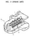
- the connector 10 as configured abovehas a problem in that, since the connecting pins 12 are exposed before connection with the main circuit board, electric current may flow via the flexible printed cable from the exposed portions to damage the magnetic head. To prevent this, according to the prior art, a short block 1 is mounted to the connector 10 in order to short between the connecting pins 12 .
- the short block 1comprises a conductive material, and, as illustrated in FIG. 2 , is formed in a rib shape such that it is inserted between the connecting pins 12 to contact them. Such a short block 1 electrically connects all of the connecting pins 12 , so that the connecting pins 12 can be shorted.
- the short block 1 mounted as discussed aboveshould be removed before the connection of the connector 10 with the main circuit board, or for a servo track writing performed before the connection with the main circuit board.
- the servo track writingis an operation that previously records a servo signal on the disk in order to write information on the hard disk drive, or to read stored information.
- the present inventionprovides hard disk drives in which a short block is not needed for an electrical short between the connecting pins, thus reducing the number of processes involved and to improve connectivity to a main circuit board.
- a hard disk driveincluding a base member; at least one disk rotatably mounted on the base member; a head stack assembly rotatably mounted on the base member to record data on the disk and to read data recorded on the disk; a voice coil motor to provide the head stack assembly with a rotating force using interaction with a coil provided in the head stack assembly; and a connector to connect between the head stack assembly and a main circuit board controlling the same, the connector comprising a bracket comprising an insulating material, connecting pins arranged in the bracket so as to be spaced apart from one another, and comprising a conductive material, and a common connecting portion extending in a direction that the connecting pins are arranged, and comprising a conductive material, wherein the connecting pins all contact the common connecting portion to form electrical shorts before the connecting pins are connected to the main circuit board, and the connecting pins each are resiliently deformed to be spaced apart from the common connecting portion in response to the connecting pins being connected to the main circuit board.
- a connectorcomprising connecting pins arranges so as to be spaced apart from one another; and a connecting member to contact the connecting pins and cause an electrical short in response to no external force being applied to the connecting pins; wherein the electrical short is removed in response to an external force being applied to the connecting pins.
- FIG. 1is a perspective view illustrating an example of a connector provided in a hard disk drive according to the prior art
- FIG. 2is a perspective view illustrating a state that a short block is mounted to the connector in FIG. 1 ;
- FIGS. 3 and 4are exploded perspective views illustrating the upper and lower portions, respectively, of a hard disk drive according to an embodiment of the present invention
- FIG. 5is a partially enlarged perspective view illustrating a portion in FIG. 4 ;
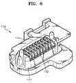
- FIG. 6is a perspective view illustrating the connector in FIG. 5 ;
- FIG. 7illustrates a sectional view of FIG. 6 .
- FIG. 8is a sectional view illustrating a state in which a main circuit board is connected with the connector of FIG. 7 .
- FIG. 3is an exploded perspective view illustrating an upper portion of a hard disk drive according to the present invention
- FIG. 4is an exploded perspective view illustrating a lower portion of the hard disk drive of FIG. 3 .
- the hard disk drive 100 of the present inventionincludes a base member 101 and a cover member 102 coupled together to form a sealed inner space therebetween.
- the inner spacethere is one or more disks 110 of data recording medium, a spindle motor 120 , a head stack assembly 130 , and a voice coil motor 140 .
- the base member 101 and the cover member 102may comprise, for example, stainless steel or aluminum, and may be coupled to each other by screws or other such adhesion methods.
- One or more disks 110are mounted on the base member 101 .
- the spindle motor 120is a device to rotate the disk 110 , and is fixedly mounted to the base member 101 .
- the head stack assembly 130is an element to record data on the disk 110 , or to read recorded data, and is rotatably mounted about a pivot axis 101 a of the base member 101 .
- the head stack assembly 130includes an arm 131 provided to the pivot axis 101 a , a suspension 132 coupled to a free end of the arm 131 , a slider 133 coupled to the suspension 132 , and a magnetic head 134 provided to the slider 133 to record and read data.
- the suspension 132supports the slider 133 such that the slider 133 is resiliently biased toward the surface of the disk 110 .
- the head stack assembly 130is driven by the voice coil motor 140 provided to one side of the base member 101 .
- the voice coil motor 140provides the head stack assembly 130 with a rotating force using interaction with a coil provided in a fantail 135 of the head stack assembly 130 .
- the head stack assembly 130is rotated in a direction in conformity with Fleming's left-hand rule by an interaction between a magnetic field formed by a magnet provided in the voice coil motor 140 and the electric current flowing through the coil.
- the slider 133 provided to a leading end of the suspension 132is moved toward the spindle motor 120 on the disk 110 or toward the circumference of the disk 110 .
- the voice coil motor 140rotates the arm 131 to move the slider 133 , to which the magnetic head is provided, over the data recording surface of the disk 110 .
- the slider 133rises up from the data recording surface of the disk 110 at a height balanced by a lift generated by the rotating disk 110 and a resilient force by the suspension 132 .
- the magnetic head 134 provided to the slider 133reads data from or records data to the data recording surface of the disk 110 .
- the voice coil motor 140rotates the arm 131 to move the slider 133 , to which the magnetic head 134 is provided, away from the data recording surface of the disk 110 .
- a connector 170is provided to a corner of one side of the base member 101 .
- the connector 170is connected with a flexible printed cable 150 connected with the head stack assembly 130 , and, as illustrated in FIG. 4 , passes through the base member 101 to protrude downwards, and is connected with a main circuit board 160 positioned under the base member 101 . That is, the connector 170 is connected between the head stack assembly 130 and the main circuit board 160 to allow the head stack assembly 130 to be controlled by the main circuit board 160 . Meanwhile, the main circuit board 160 is also used in controlling the voice coil motor 140 . As illustrated in FIG. 5 , the main circuit board 160 has terminals 161 to correspond on a one-to-one basis to the connecting pins 174 provided to the connector 170 , which are described later. The terminals 161 each respectively contact the connecting pins 174 so that the main circuit board 160 and the connector 170 are connected with each other.
- partition memberssuch as partition walls 172 are preferably, though not necessarily, formed between each of the adjacent connecting pins 174 .
- partition walls 172may comprise an insulating material which may be integrally formed with the bracket 171 .
- the bracket 171has a common connecting portion 175 extending in a direction in which the connecting pins 174 are arranged, and which may comprise a conductive material.
- the common connecting portion 175is disposed between the first and second row of the connecting pins 174 .
- the common connecting portion 175contacts all of the connecting pins 174 before an external force is applied to the connecting pins 174 , i.e., before the connection with the main circuit board 160 , to cause a short between the rows of connecting pins 174 .
- the common connecting portion 175may be coupled to a block 173 provided to the bracket 171 , which may comprise an insulating material, as illustrated in FIG. 7 .
- the coupling of the block 173 and the common connecting portion 175may be provided by one or more grooves 175 a formed in the common connecting portion 175 , and one or more protrusions 173 a formed in the block 173 so as to be inserted into the grooves 175 a . Also, it is possible to form protrusions in the common connecting portion 175 , and form grooves in the block 173 , so as to couple the common connecting portion 175 and the block 173 .
- the connecting pins 174 contacting the common connecting portion 175have hook portions 174 b at portions exposed outside from their body portions 174 a where a force is applied, so that edge portions of the hook portions 174 b contact a side portion of the common connecting portion 175 .
- the edge portions of the hook portions 174 bare preferably, though not necessarily, curved.
- Such hook portions 174 bcan be resiliently deformed while an external force is applied thereto along with the connection with the main circuit board 160 . Also, the hook portions 174 b can return to their original states if the external force is removed.
- the hook portions 174 bare preferably, though not necessarily, partially protruded from inside of the bracket 171 at a predetermined height so as to be resiliently deformed inside the bracket 171 while maintaining the contact state with the terminals 161 .
- a shape of the hook portion 174 bis not limited to these illustrated embodiments, but may be formed in various shapes to perform a function as described above.
- the connecting pins 174each contact the common connecting portion 175 before the connection with the main circuit board 160 , or before the performance of a servo track writing, thus to be shorted with other connecting pins, so that the conventional short block 1 as illustrated in FIGS. 1 and 2 is not required, end therefore an additional process for removing the short block 1 can be accordingly removed.
- an incomplete connection with the main circuit board 160 due to curving of the connecting pins 174can be prevented.
- connectivity between the connecting pins 174 and the main circuit board 160can be improved. Further, as illustrated in FIG.
- the connecting pins 174 contacting the main circuit board 160are resiliently deformed while maintaining the contact state with the terminals 161 , provided to the main circuit board 160 , when connected with the main circuit board 160 , thus to be separated from the side portion of the common connecting portion 175 in response to a external force being applied. Consequently, the shorted state between the connecting pins 174 can be released so that the connecting pins 174 can perform their original functions.
- the width of the block 173can be formed substantially identical to that of the common connecting portion 175 such that the edge portions of the hook portions 174 b are smoothly and slidably moved from the side portion of the common connecting portion 175 to the side portion of the block 173 .
- the inventionis not limited to this discussed embodiment.
- the connecting pinsare shorted together by the common connecting portion before the connection with the main circuit board, and, if connected with the main circuit board, the shorted state by the common connecting portion can be released.
- the conventional short blockis not required so that an additional process for removing the conventional short block is accordingly not required.
- the incomplete connection with the main circuit board due to curving of the connecting pinscan be prevented.
Landscapes
- Moving Of Heads (AREA)
- Coupling Device And Connection With Printed Circuit (AREA)
Abstract
Description
Claims (19)
Applications Claiming Priority (2)
| Application Number | Priority Date | Filing Date | Title |
|---|---|---|---|
| KR10-2005-0055890 | 2005-06-27 | ||
| KR1020050055890AKR100630751B1 (en) | 2005-06-27 | 2005-06-27 | Connector and hard disk drive with same |
Publications (2)
| Publication Number | Publication Date |
|---|---|
| US20060292899A1 US20060292899A1 (en) | 2006-12-28 |
| US7391588B2true US7391588B2 (en) | 2008-06-24 |
Family
ID=37568136
Family Applications (1)
| Application Number | Title | Priority Date | Filing Date |
|---|---|---|---|
| US11/442,238Expired - Fee RelatedUS7391588B2 (en) | 2005-06-27 | 2006-05-30 | Hard disk drive connector having connector pins that deform away from a central shorting post in response to an external force |
Country Status (3)
| Country | Link |
|---|---|
| US (1) | US7391588B2 (en) |
| JP (1) | JP4965169B2 (en) |
| KR (1) | KR100630751B1 (en) |
Cited By (1)
| Publication number | Priority date | Publication date | Assignee | Title |
|---|---|---|---|---|
| US20090147391A1 (en)* | 2007-11-30 | 2009-06-11 | Fujitsu Limited | Information storage apparatus, information storage arrangement and information storage arrangement kit |
Citations (20)
| Publication number | Priority date | Publication date | Assignee | Title |
|---|---|---|---|---|
| USRE33831E (en)* | 1983-03-03 | 1992-02-25 | International Business Machines Corporation | Non-shortning pin system |
| US5316486A (en)* | 1990-05-29 | 1994-05-31 | Kel Corporation | Connector assembly for film circuitry |
| JPH07201421A (en) | 1993-12-10 | 1995-08-04 | Burndy Corp | Printed circuit board stabilizer of card edge connector |
| JPH08180943A (en) | 1994-12-22 | 1996-07-12 | Hirose Electric Co Ltd | Circuit board insertion type electrical connector |
| US6022236A (en)* | 1998-08-24 | 2000-02-08 | Hon Hai Precision Ind. Co., Ltd. | Electrical terminal |
| US6056590A (en)* | 1996-06-25 | 2000-05-02 | Fujitsu Takamisawa Component Limited | Connector having internal switch and fabrication method thereof |
| US6174183B1 (en)* | 1997-12-19 | 2001-01-16 | Matsushita Electric Works, Ltd. | Coaxial cable connector with normally closed switch |
| US6398590B2 (en)* | 2000-07-11 | 2002-06-04 | Tyco Electronics Corporation | Nonpolarized electrical connector assembly especially for use as automotive squib connector |
| US6482050B1 (en)* | 1998-01-31 | 2002-11-19 | Fci Americas Technology, Inc. | Contact for electrical component socket |
| US6557761B1 (en)* | 1999-11-16 | 2003-05-06 | Yamaichi Electronics Co., Ltd. | Card detect switch for card connector |
| US6618261B1 (en)* | 2002-06-04 | 2003-09-09 | Ford Global Technologies, Llc | Electrical sensor mount |
| JP2004207165A (en) | 2002-12-26 | 2004-07-22 | Tyco Electronics Amp Kk | Electric connector |
| US6794589B2 (en)* | 2002-05-30 | 2004-09-21 | Itt Manufacturing Enterprises, Inc. | Multiple electrical switch arrangement |
| US6945801B2 (en)* | 2003-01-23 | 2005-09-20 | Fci Americas Technology, Inc. | Electrical connector having connector position assurance member |
| US6979785B2 (en)* | 2004-04-09 | 2005-12-27 | Matsushita Electric Industrial Co., Ltd. | Multidirectional operation switch |
| US7029285B2 (en)* | 2001-09-13 | 2006-04-18 | Nec Corporation | Computer system, switch connector, and method for controlling operations of the computer system |
| US20060110964A1 (en)* | 2004-11-24 | 2006-05-25 | Kamath Shashidhar M | Shorting bar connector |
| US7052284B2 (en)* | 2004-04-16 | 2006-05-30 | Hon Hai Precision Ind. Co., Ltd. | Electrical contact having shorting member with reduced self-inductance |
| US7102088B2 (en)* | 2004-07-23 | 2006-09-05 | Hon Hai Precision Ind. Co., Ltd | Multi-direction switch |
| US7247039B2 (en)* | 2005-02-02 | 2007-07-24 | Amphenol-Tuchel Electronics Gmbh | Contact safety device for pin-and-socket connectors with a shorting bar with an integrated circuit element |
Family Cites Families (5)
| Publication number | Priority date | Publication date | Assignee | Title |
|---|---|---|---|---|
| JPH0512956Y2 (en)* | 1987-09-08 | 1993-04-05 | ||
| JP3510264B2 (en) | 1994-07-15 | 2004-03-22 | バーグ・テクノロジー・インコーポレーテッド | Long arm compression connector with bump header |
| JPH08250226A (en)* | 1995-03-13 | 1996-09-27 | Sumitomo Wiring Syst Ltd | Connector |
| KR100404550B1 (en) | 2001-06-16 | 2003-11-05 | 한국몰렉스 주식회사 | Signal electrical transmission of computer hard-disk and manufacture method |
| JP3991988B2 (en)* | 2004-01-13 | 2007-10-17 | 松下電工株式会社 | PCB connection structure |
- 2005
- 2005-06-27KRKR1020050055890Apatent/KR100630751B1/ennot_activeExpired - Fee Related
- 2006
- 2006-05-30USUS11/442,238patent/US7391588B2/ennot_activeExpired - Fee Related
- 2006-06-27JPJP2006176739Apatent/JP4965169B2/ennot_activeExpired - Fee Related
Patent Citations (20)
| Publication number | Priority date | Publication date | Assignee | Title |
|---|---|---|---|---|
| USRE33831E (en)* | 1983-03-03 | 1992-02-25 | International Business Machines Corporation | Non-shortning pin system |
| US5316486A (en)* | 1990-05-29 | 1994-05-31 | Kel Corporation | Connector assembly for film circuitry |
| JPH07201421A (en) | 1993-12-10 | 1995-08-04 | Burndy Corp | Printed circuit board stabilizer of card edge connector |
| JPH08180943A (en) | 1994-12-22 | 1996-07-12 | Hirose Electric Co Ltd | Circuit board insertion type electrical connector |
| US6056590A (en)* | 1996-06-25 | 2000-05-02 | Fujitsu Takamisawa Component Limited | Connector having internal switch and fabrication method thereof |
| US6174183B1 (en)* | 1997-12-19 | 2001-01-16 | Matsushita Electric Works, Ltd. | Coaxial cable connector with normally closed switch |
| US6482050B1 (en)* | 1998-01-31 | 2002-11-19 | Fci Americas Technology, Inc. | Contact for electrical component socket |
| US6022236A (en)* | 1998-08-24 | 2000-02-08 | Hon Hai Precision Ind. Co., Ltd. | Electrical terminal |
| US6557761B1 (en)* | 1999-11-16 | 2003-05-06 | Yamaichi Electronics Co., Ltd. | Card detect switch for card connector |
| US6398590B2 (en)* | 2000-07-11 | 2002-06-04 | Tyco Electronics Corporation | Nonpolarized electrical connector assembly especially for use as automotive squib connector |
| US7029285B2 (en)* | 2001-09-13 | 2006-04-18 | Nec Corporation | Computer system, switch connector, and method for controlling operations of the computer system |
| US6794589B2 (en)* | 2002-05-30 | 2004-09-21 | Itt Manufacturing Enterprises, Inc. | Multiple electrical switch arrangement |
| US6618261B1 (en)* | 2002-06-04 | 2003-09-09 | Ford Global Technologies, Llc | Electrical sensor mount |
| JP2004207165A (en) | 2002-12-26 | 2004-07-22 | Tyco Electronics Amp Kk | Electric connector |
| US6945801B2 (en)* | 2003-01-23 | 2005-09-20 | Fci Americas Technology, Inc. | Electrical connector having connector position assurance member |
| US6979785B2 (en)* | 2004-04-09 | 2005-12-27 | Matsushita Electric Industrial Co., Ltd. | Multidirectional operation switch |
| US7052284B2 (en)* | 2004-04-16 | 2006-05-30 | Hon Hai Precision Ind. Co., Ltd. | Electrical contact having shorting member with reduced self-inductance |
| US7102088B2 (en)* | 2004-07-23 | 2006-09-05 | Hon Hai Precision Ind. Co., Ltd | Multi-direction switch |
| US20060110964A1 (en)* | 2004-11-24 | 2006-05-25 | Kamath Shashidhar M | Shorting bar connector |
| US7247039B2 (en)* | 2005-02-02 | 2007-07-24 | Amphenol-Tuchel Electronics Gmbh | Contact safety device for pin-and-socket connectors with a shorting bar with an integrated circuit element |
Cited By (1)
| Publication number | Priority date | Publication date | Assignee | Title |
|---|---|---|---|---|
| US20090147391A1 (en)* | 2007-11-30 | 2009-06-11 | Fujitsu Limited | Information storage apparatus, information storage arrangement and information storage arrangement kit |
Also Published As
| Publication number | Publication date |
|---|---|
| KR100630751B1 (en) | 2006-10-02 |
| JP4965169B2 (en) | 2012-07-04 |
| US20060292899A1 (en) | 2006-12-28 |
| JP2007012614A (en) | 2007-01-18 |
Similar Documents
| Publication | Publication Date | Title |
|---|---|---|
| KR100296477B1 (en) | Gasket Frames for Actuator Flexible Cable Grounding | |
| USRE37869E1 (en) | Head signal supply/retrieval structure for magnetic disc drive | |
| WO1999066500A1 (en) | Low inductance flex-to-pcb spring connector for disc drive | |
| US6721135B2 (en) | Printed circuit cable connector attachment assembly | |
| US5757582A (en) | Miniature hard disk drive system | |
| US10811041B2 (en) | Magnetic disk drive including actuator assembly, flexible print circuit board and control circuit board | |
| US20040219804A1 (en) | Electrical interconnect scheme | |
| JP4109654B2 (en) | Flexible printed circuit for spindle motor and disk drive having the same | |
| EP1884927A2 (en) | Head gimbal assembly and hard disk drive having the same | |
| JP2021044036A (en) | Connected devices and disk devices | |
| US5909338A (en) | Magnetic disk drive having a Z-shaped grounding portion in the flex circuit cable | |
| CN110933834A (en) | Wiring board unit, actuator assembly, and disk device provided with the same | |
| US20010049210A1 (en) | 3.5 inch form factor compatible connector for 2.5 inch form factor disc drive | |
| US6754041B2 (en) | Disc drive cover portion thermally coupled to a preamplifier | |
| US5905609A (en) | Magnetic disk drive having a VCM plate which includes an elongated protrusion for securing a flex clamp to the base | |
| US20190295576A1 (en) | Disk device and method of assembling the same | |
| US6135782A (en) | Electrical compression connector for a disc drive | |
| US7391588B2 (en) | Hard disk drive connector having connector pins that deform away from a central shorting post in response to an external force | |
| JP3658458B2 (en) | Magnetic disk unit | |
| EP2031585A1 (en) | Arm plate, head stack assembly comprising the same, and hard disk drive comprising the head stack assembly | |
| US20050024776A1 (en) | Head suspension assembly, head stack assembly and disk apparatus | |
| US7158347B2 (en) | Grounding connection between suspension flexure and arm actuator | |
| CN100550181C (en) | Data storage device and the connector that is arranged on wherein | |
| KR100518522B1 (en) | Suspension assembly for hard disk drive | |
| KR100498428B1 (en) | Magnetic head signal wire connection structure of hard disk drive |
Legal Events
| Date | Code | Title | Description |
|---|---|---|---|
| AS | Assignment | Owner name:SAMSUNG ELECTRONICS CO., LTD., KOREA, REPUBLIC OF Free format text:ASSIGNMENT OF ASSIGNORS INTEREST;ASSIGNORS:CHO, KYOUNG-MAN;LEE, JAE-SUK;REEL/FRAME:017948/0996 Effective date:20060502 | |
| STCF | Information on status: patent grant | Free format text:PATENTED CASE | |
| CC | Certificate of correction | ||
| FPAY | Fee payment | Year of fee payment:4 | |
| AS | Assignment | Owner name:SEAGATE TECHNOLOGY INTERNATIONAL, CAYMAN ISLANDS Free format text:ASSIGNMENT OF ASSIGNORS INTEREST;ASSIGNOR:SAMSUNG ELECTRONICS CO., LTD.;REEL/FRAME:028153/0689 Effective date:20111219 | |
| FPAY | Fee payment | Year of fee payment:8 | |
| AS | Assignment | Owner name:SAMSUNG ELECTRONICS CO., LTD., KOREA, REPUBLIC OF Free format text:CORRECTIVE ASSIGNMENT TO CORRECT THE REMOVE ERRONEOUSLY FILED NO. 7255478 FROM SCHEDULE PREVIOUSLY RECORDED AT REEL: 028153 FRAME: 0689. ASSIGNOR(S) HEREBY CONFIRMS THE ASSIGNMENT;ASSIGNOR:SAMSUNG ELECTRONICS CO., LTD.;REEL/FRAME:040001/0920 Effective date:20160720 | |
| FEPP | Fee payment procedure | Free format text:MAINTENANCE FEE REMINDER MAILED (ORIGINAL EVENT CODE: REM.); ENTITY STATUS OF PATENT OWNER: LARGE ENTITY | |
| LAPS | Lapse for failure to pay maintenance fees | Free format text:PATENT EXPIRED FOR FAILURE TO PAY MAINTENANCE FEES (ORIGINAL EVENT CODE: EXP.); ENTITY STATUS OF PATENT OWNER: LARGE ENTITY | |
| STCH | Information on status: patent discontinuation | Free format text:PATENT EXPIRED DUE TO NONPAYMENT OF MAINTENANCE FEES UNDER 37 CFR 1.362 | |
| FP | Lapsed due to failure to pay maintenance fee | Effective date:20200624 |