US7389909B2 - Bag-in-box container - Google Patents
Bag-in-box containerDownload PDFInfo
- Publication number
- US7389909B2 US7389909B2US10/955,702US95570204AUS7389909B2US 7389909 B2US7389909 B2US 7389909B2US 95570204 AUS95570204 AUS 95570204AUS 7389909 B2US7389909 B2US 7389909B2
- Authority
- US
- United States
- Prior art keywords
- panels
- panel
- flaps
- tubular body
- bag
- Prior art date
- Legal status (The legal status is an assumption and is not a legal conclusion. Google has not performed a legal analysis and makes no representation as to the accuracy of the status listed.)
- Expired - Fee Related, expires
Links
- 239000000463materialSubstances0.000claimsabstractdescription22
- 239000007788liquidSubstances0.000claimsabstractdescription18
- 239000011087paperboardSubstances0.000claimsabstractdescription18
- 125000006850spacer groupChemical group0.000claimsdescription16
- 239000000123paperSubstances0.000claimsdescription8
- 230000001154acute effectEffects0.000claimsdescription3
- 239000012530fluidSubstances0.000claimsdescription2
- 230000002401inhibitory effectEffects0.000claimsdescription2
- 238000000926separation methodMethods0.000claimsdescription2
- 235000013361beverageNutrition0.000abstractdescription25
- 238000003780insertionMethods0.000description11
- 230000037431insertionEffects0.000description11
- 238000003197gene knockdownMethods0.000description5
- 239000003292glueSubstances0.000description4
- 238000000034methodMethods0.000description4
- 239000004033plasticSubstances0.000description4
- 229920003023plasticPolymers0.000description4
- 239000000428dustSubstances0.000description3
- 235000013305foodNutrition0.000description3
- 230000002093peripheral effectEffects0.000description3
- 238000004064recyclingMethods0.000description3
- 235000014347soupsNutrition0.000description3
- 238000003860storageMethods0.000description3
- 230000015572biosynthetic processEffects0.000description2
- 238000004140cleaningMethods0.000description2
- 239000002131composite materialSubstances0.000description2
- 239000012056semi-solid materialSubstances0.000description2
- 239000004698PolyethyleneSubstances0.000description1
- 238000004026adhesive bondingMethods0.000description1
- 238000010276constructionMethods0.000description1
- 238000011109contaminationMethods0.000description1
- 230000001351cycling effectEffects0.000description1
- 230000008034disappearanceEffects0.000description1
- 238000006073displacement reactionMethods0.000description1
- 239000000446fuelSubstances0.000description1
- 238000004519manufacturing processMethods0.000description1
- 239000002184metalSubstances0.000description1
- 238000012986modificationMethods0.000description1
- 230000004048modificationEffects0.000description1
- -1polyethylenePolymers0.000description1
- 229920000573polyethylenePolymers0.000description1
- 238000003825pressingMethods0.000description1
- 230000001737promoting effectEffects0.000description1
- 230000003014reinforcing effectEffects0.000description1
- 239000007787solidSubstances0.000description1
Images


Classifications
- B—PERFORMING OPERATIONS; TRANSPORTING
- B65—CONVEYING; PACKING; STORING; HANDLING THIN OR FILAMENTARY MATERIAL
- B65D—CONTAINERS FOR STORAGE OR TRANSPORT OF ARTICLES OR MATERIALS, e.g. BAGS, BARRELS, BOTTLES, BOXES, CANS, CARTONS, CRATES, DRUMS, JARS, TANKS, HOPPERS, FORWARDING CONTAINERS; ACCESSORIES, CLOSURES, OR FITTINGS THEREFOR; PACKAGING ELEMENTS; PACKAGES
- B65D5/00—Rigid or semi-rigid containers of polygonal cross-section, e.g. boxes, cartons or trays, formed by folding or erecting one or more blanks made of paper
- B65D5/36—Rigid or semi-rigid containers of polygonal cross-section, e.g. boxes, cartons or trays, formed by folding or erecting one or more blanks made of paper specially constructed to allow collapsing and re-erecting without disengagement of side or bottom connections
- B65D5/3607—Rigid or semi-rigid containers of polygonal cross-section, e.g. boxes, cartons or trays, formed by folding or erecting one or more blanks made of paper specially constructed to allow collapsing and re-erecting without disengagement of side or bottom connections formed by folding or erecting a single blank
- B65D5/3614—Rigid or semi-rigid containers of polygonal cross-section, e.g. boxes, cartons or trays, formed by folding or erecting one or more blanks made of paper specially constructed to allow collapsing and re-erecting without disengagement of side or bottom connections formed by folding or erecting a single blank to form a tubular body, at least one of the ends of the body remaining connected
- B65D5/3621—Rigid or semi-rigid containers of polygonal cross-section, e.g. boxes, cartons or trays, formed by folding or erecting one or more blanks made of paper specially constructed to allow collapsing and re-erecting without disengagement of side or bottom connections formed by folding or erecting a single blank to form a tubular body, at least one of the ends of the body remaining connected collapsed along two fold lines of the tubular body
- B—PERFORMING OPERATIONS; TRANSPORTING
- B65—CONVEYING; PACKING; STORING; HANDLING THIN OR FILAMENTARY MATERIAL
- B65D—CONTAINERS FOR STORAGE OR TRANSPORT OF ARTICLES OR MATERIALS, e.g. BAGS, BARRELS, BOTTLES, BOXES, CANS, CARTONS, CRATES, DRUMS, JARS, TANKS, HOPPERS, FORWARDING CONTAINERS; ACCESSORIES, CLOSURES, OR FITTINGS THEREFOR; PACKAGING ELEMENTS; PACKAGES
- B65D5/00—Rigid or semi-rigid containers of polygonal cross-section, e.g. boxes, cartons or trays, formed by folding or erecting one or more blanks made of paper
- B65D5/02—Rigid or semi-rigid containers of polygonal cross-section, e.g. boxes, cartons or trays, formed by folding or erecting one or more blanks made of paper by folding or erecting a single blank to form a tubular body with or without subsequent folding operations, or the addition of separate elements, to close the ends of the body
- B65D5/10—Rigid or semi-rigid containers of polygonal cross-section, e.g. boxes, cartons or trays, formed by folding or erecting one or more blanks made of paper by folding or erecting a single blank to form a tubular body with or without subsequent folding operations, or the addition of separate elements, to close the ends of the body with end closures formed by inward-folding of self-locking flaps hinged to tubular body
- B—PERFORMING OPERATIONS; TRANSPORTING
- B65—CONVEYING; PACKING; STORING; HANDLING THIN OR FILAMENTARY MATERIAL
- B65D—CONTAINERS FOR STORAGE OR TRANSPORT OF ARTICLES OR MATERIALS, e.g. BAGS, BARRELS, BOTTLES, BOXES, CANS, CARTONS, CRATES, DRUMS, JARS, TANKS, HOPPERS, FORWARDING CONTAINERS; ACCESSORIES, CLOSURES, OR FITTINGS THEREFOR; PACKAGING ELEMENTS; PACKAGES
- B65D5/00—Rigid or semi-rigid containers of polygonal cross-section, e.g. boxes, cartons or trays, formed by folding or erecting one or more blanks made of paper
- B65D5/40—Rigid or semi-rigid containers of polygonal cross-section, e.g. boxes, cartons or trays, formed by folding or erecting one or more blanks made of paper specially constructed to contain liquids
- B—PERFORMING OPERATIONS; TRANSPORTING
- B65—CONVEYING; PACKING; STORING; HANDLING THIN OR FILAMENTARY MATERIAL
- B65D—CONTAINERS FOR STORAGE OR TRANSPORT OF ARTICLES OR MATERIALS, e.g. BAGS, BARRELS, BOTTLES, BOXES, CANS, CARTONS, CRATES, DRUMS, JARS, TANKS, HOPPERS, FORWARDING CONTAINERS; ACCESSORIES, CLOSURES, OR FITTINGS THEREFOR; PACKAGING ELEMENTS; PACKAGES
- B65D5/00—Rigid or semi-rigid containers of polygonal cross-section, e.g. boxes, cartons or trays, formed by folding or erecting one or more blanks made of paper
- B65D5/42—Details of containers or of foldable or erectable container blanks
- B65D5/44—Integral, inserted or attached portions forming internal or external fittings
- B65D5/46—Handles
- B65D5/46072—Handles integral with the container
- B65D5/46088—Handles integral with the container formed by extensions of closure flaps, by closure flaps or by extensions of side flaps of a container formed by folding a blank to form a tubular body
- B65D5/46096—Handles integral with the container formed by extensions of closure flaps, by closure flaps or by extensions of side flaps of a container formed by folding a blank to form a tubular body two opposite closure flaps being provided with handle elements which are in contact with each other
- B—PERFORMING OPERATIONS; TRANSPORTING
- B65—CONVEYING; PACKING; STORING; HANDLING THIN OR FILAMENTARY MATERIAL
- B65D—CONTAINERS FOR STORAGE OR TRANSPORT OF ARTICLES OR MATERIALS, e.g. BAGS, BARRELS, BOTTLES, BOXES, CANS, CARTONS, CRATES, DRUMS, JARS, TANKS, HOPPERS, FORWARDING CONTAINERS; ACCESSORIES, CLOSURES, OR FITTINGS THEREFOR; PACKAGING ELEMENTS; PACKAGES
- B65D5/00—Rigid or semi-rigid containers of polygonal cross-section, e.g. boxes, cartons or trays, formed by folding or erecting one or more blanks made of paper
- B65D5/42—Details of containers or of foldable or erectable container blanks
- B65D5/44—Integral, inserted or attached portions forming internal or external fittings
- B65D5/50—Internal supporting or protecting elements for contents
- B65D5/5002—Integral elements for containers having tubular body walls
- B65D5/5004—Integral elements for containers having tubular body walls formed as an extension of the end closures
- B—PERFORMING OPERATIONS; TRANSPORTING
- B65—CONVEYING; PACKING; STORING; HANDLING THIN OR FILAMENTARY MATERIAL
- B65D—CONTAINERS FOR STORAGE OR TRANSPORT OF ARTICLES OR MATERIALS, e.g. BAGS, BARRELS, BOTTLES, BOXES, CANS, CARTONS, CRATES, DRUMS, JARS, TANKS, HOPPERS, FORWARDING CONTAINERS; ACCESSORIES, CLOSURES, OR FITTINGS THEREFOR; PACKAGING ELEMENTS; PACKAGES
- B65D5/00—Rigid or semi-rigid containers of polygonal cross-section, e.g. boxes, cartons or trays, formed by folding or erecting one or more blanks made of paper
- B65D5/42—Details of containers or of foldable or erectable container blanks
- B65D5/44—Integral, inserted or attached portions forming internal or external fittings
- B65D5/50—Internal supporting or protecting elements for contents
- B65D5/5028—Elements formed separately from the container body
- B65D5/5035—Paper elements
- B—PERFORMING OPERATIONS; TRANSPORTING
- B65—CONVEYING; PACKING; STORING; HANDLING THIN OR FILAMENTARY MATERIAL
- B65D—CONTAINERS FOR STORAGE OR TRANSPORT OF ARTICLES OR MATERIALS, e.g. BAGS, BARRELS, BOTTLES, BOXES, CANS, CARTONS, CRATES, DRUMS, JARS, TANKS, HOPPERS, FORWARDING CONTAINERS; ACCESSORIES, CLOSURES, OR FITTINGS THEREFOR; PACKAGING ELEMENTS; PACKAGES
- B65D5/00—Rigid or semi-rigid containers of polygonal cross-section, e.g. boxes, cartons or trays, formed by folding or erecting one or more blanks made of paper
- B65D5/42—Details of containers or of foldable or erectable container blanks
- B65D5/56—Linings or internal coatings, e.g. pre-formed trays provided with a blow- or thermoformed layer
- B65D5/60—Loose, or loosely attached, linings
- B—PERFORMING OPERATIONS; TRANSPORTING
- B65—CONVEYING; PACKING; STORING; HANDLING THIN OR FILAMENTARY MATERIAL
- B65D—CONTAINERS FOR STORAGE OR TRANSPORT OF ARTICLES OR MATERIALS, e.g. BAGS, BARRELS, BOTTLES, BOXES, CANS, CARTONS, CRATES, DRUMS, JARS, TANKS, HOPPERS, FORWARDING CONTAINERS; ACCESSORIES, CLOSURES, OR FITTINGS THEREFOR; PACKAGING ELEMENTS; PACKAGES
- B65D5/00—Rigid or semi-rigid containers of polygonal cross-section, e.g. boxes, cartons or trays, formed by folding or erecting one or more blanks made of paper
- B65D5/42—Details of containers or of foldable or erectable container blanks
- B65D5/72—Contents-dispensing means
- B65D5/724—Internal fittings facilitating the discharge of contents, e.g. guiding panels, movable bottoms or lifting strips
- B—PERFORMING OPERATIONS; TRANSPORTING
- B65—CONVEYING; PACKING; STORING; HANDLING THIN OR FILAMENTARY MATERIAL
- B65D—CONTAINERS FOR STORAGE OR TRANSPORT OF ARTICLES OR MATERIALS, e.g. BAGS, BARRELS, BOTTLES, BOXES, CANS, CARTONS, CRATES, DRUMS, JARS, TANKS, HOPPERS, FORWARDING CONTAINERS; ACCESSORIES, CLOSURES, OR FITTINGS THEREFOR; PACKAGING ELEMENTS; PACKAGES
- B65D5/00—Rigid or semi-rigid containers of polygonal cross-section, e.g. boxes, cartons or trays, formed by folding or erecting one or more blanks made of paper
- B65D5/42—Details of containers or of foldable or erectable container blanks
- B65D5/72—Contents-dispensing means
- B65D5/74—Spouts
- B65D5/746—Spouts formed separately from the container
- B—PERFORMING OPERATIONS; TRANSPORTING
- B65—CONVEYING; PACKING; STORING; HANDLING THIN OR FILAMENTARY MATERIAL
- B65D—CONTAINERS FOR STORAGE OR TRANSPORT OF ARTICLES OR MATERIALS, e.g. BAGS, BARRELS, BOTTLES, BOXES, CANS, CARTONS, CRATES, DRUMS, JARS, TANKS, HOPPERS, FORWARDING CONTAINERS; ACCESSORIES, CLOSURES, OR FITTINGS THEREFOR; PACKAGING ELEMENTS; PACKAGES
- B65D77/00—Packages formed by enclosing articles or materials in preformed containers, e.g. boxes, cartons, sacks or bags
- B65D77/04—Articles or materials enclosed in two or more containers disposed one within another
- B65D77/06—Liquids or semi-liquids or other materials or articles enclosed in flexible containers disposed within rigid containers
- B65D77/062—Flexible containers disposed within polygonal containers formed by folding a carton blank
- B65D77/065—Spouts, pouring necks or discharging tubes fixed to or integral with the flexible container
- B—PERFORMING OPERATIONS; TRANSPORTING
- B65—CONVEYING; PACKING; STORING; HANDLING THIN OR FILAMENTARY MATERIAL
- B65D—CONTAINERS FOR STORAGE OR TRANSPORT OF ARTICLES OR MATERIALS, e.g. BAGS, BARRELS, BOTTLES, BOXES, CANS, CARTONS, CRATES, DRUMS, JARS, TANKS, HOPPERS, FORWARDING CONTAINERS; ACCESSORIES, CLOSURES, OR FITTINGS THEREFOR; PACKAGING ELEMENTS; PACKAGES
- B65D2231/00—Means for facilitating the complete expelling of the contents
Definitions
- the present inventionrelates to bag-in-box style cartons and containers, of the type in which a non-self-supporting plastic bag or the like is positioned in a surrounding, supporting container structure, the entire package being disposable after a single use.
- the present inventionalso relates to large volume urn-style beverage containers.
- Urn-style beverage containersfor the containment and controlled incremental dispensing of a relatively large volume (2+ gallons) of liquid are known.
- urn-style beverage containersare reusable devices of metal and plastic, which can be heavy, and which, of course, require cleaning after each use.
- Various versions of such devicesare known as “pump pots”; “air pots”; various all-plastic urns (sold under the registered trademark “CamServers”) and buckets with spigots, both manufactured by Cambro Manufacturing Company of Huntington Beach, Calif.
- the rectangular bag-in-box constructionis also shown in Geshay, U.S. Pat. No. 6,062,431, owned by BIB Pak, Inc., of Racine, Wis.
- Retail and wholesale (catering) food service operatorstypically have need of such large volume beverage containers.
- permanent, reusable urnsmay be subject to various disadvantages and/or impose certain costs of operation, upon retail customers and/or retail and wholesale food service operators.
- caterersmust address the need to physically retrieve the urns, requiring expenditures of labor and fuel.
- the urnsmust be cleaned and stored, again requiring expenditures of labor, cleaning supplies, and storage space.
- Reusable urnsare often the subject of theft or “mysterious” disappearance, imposing unscheduled replacement costs, as well as the replacement costs associated with the cycling out of units as a result of normal wear and tear. If units are lost/stolen or in disrepair, the business operator runs the risk of lost sales.
- a large volume dispenserwhich is disposable, and preferably fabricated in large part from recyclable materials, and which is configured for easy knock-down for recycling and disposal.
- the present inventionis directed to a dispensing container, operably configured to be positioned upon a substantially flat, horizontal surface, for the facilitated dispensing of fluent material.
- the dispensing containercomprises a generally tubular body, having a vertical axis, a depth axis and a transverse axis.
- a closure structureis disposed proximate an opening in an upper portion of the tubular body.
- the closure structureincludes a handle structure, which is disposed in a recessed position within an upper opening of the generally tubular body and extending no higher than an upper edge region of the generally tubular body.
- the generally tubular bodyfurther has a plurality of sidewalls.
- a nozzle receiving apertureis operably disposed in one of the plurality of sidewalls.
- An inner flow prompting rampis operably positioned within the generally tubular body.
- the inner flow prompting ramphas a lower end, disposed adjacent the sidewall of the generally tubular body in which the nozzle receiving aperture is disposed, and a higher end, disposed adjacent an opposite sidewall thereto, and an inclined surface extending between the lower end and the upper end.
- the lower end of the inner flow prompting rampis disposed at a distance above the bottom of the generally tubular body approximately equal to the distance between the bottom of the generally tubular body and a bottom peripheral region of the nozzle receiving aperture.
- the generally tubular bodyis preferably formed from a first blank of at least one of the following materials: paper; paperboard; corrugated paperboard.
- the generally tubular bodycomprises a front wall, a rear wall disposed parallel to the front wall, and two sidewalls, disposed parallel to one another, perpendicular to the front and rear walls and extending therebetween.
- the closure structurepreferably comprises first and second foldable sidewall top flaps, emanating from top edge regions of the sidewalls.
- Each of the first and second foldable sidewall top flapspreferably includes a first panel, foldably connected to one of the sidewalls, and positioned at an acute included angle relative thereto.
- Each of the first and second foldable sidewall top flapspreferably includes a second panel, foldably connected to one of the first panels, each of the second panels being folded upwardly, parallel to the sidewalls and in juxtaposed overlying relation to one another, the second panels having top edges that are disposed no higher than the upper edge region of the generally tubular body.
- a foldable front wall top flapemanates from a top edge region of the front wall.
- a foldable rear wall top flapemanates from a top edge region of the rear wall.
- the foldable front and rear wall top flapseach includes first panels, foldably connected to the front and rear walls, respectively, and positioned substantially perpendicular thereto.
- the foldable front and rear wall top flapseach further include second panels, foldably connected to the respective first panels of the front and rear wall top flaps, and emanating downwardly therefrom, the second panels of the front and rear wall top flaps being disposed in positions interengaging with the second panels of the first and second sidewall top flaps, to preclude undesired dislodgement of the second panels of the first and second sidewall top flaps.
- the closure structurepreferably further comprises at least one slot in each of the first panels of the first and second sidewall top flaps.
- at least one hooked tabemanates from each of the first panels of the front and rear wall top flaps.
- the hooked tabsare preferably configured to be engagingly received in the slots, when the second panels of the front and rear wall top flaps are folded over into interengagement with the second panels of the first and second sidewall top flaps.
- the closure structurefurther comprises at least one notch in each of the second panels of the first and second sidewall top flaps, the notches being aligned with one another when the second panels of the first and second sidewall top flaps are parallel to the sidewalls and in juxtaposed overlying relation to one another.
- a notch in at least one of the front and rear wall top flapsis operably configured to interengage with the aligned notches in the second panels of the first and second sidewall top flaps, when the second panels of the front and rear wall top flaps are folded over into interengagement with the second panels of the first and second sidewall top flaps.
- the handle structurecomprises a hand opening aperture disposed in one of the second panels of the first and second sidewall top flaps.
- a hingedly connected push-out flapis preferably disposed in the other of the second panels of the first and second sidewall top flaps.
- the push-out flappreferably has a peripheral contour substantially conforming to the peripheral contour of the hand opening aperture.
- the push out flapis configured to be pushed through the hand opening aperture, and upwardly relative thereto, to provide a grasping opening.
- the inner flow prompting ramppreferably is formed from a second blank fabricated from at least one of the following materials: paper; paperboard; corrugated paperboard.
- the inner flow prompting rampis formed from a separate second blank of foldable material, which is insertably received into the generally tubular body.
- the inner flow prompting rampis formed from a substantially cruciform blank having a central rectangular panel, rectangular panels emanating from front and rear edge regions of the central panel, and trapezoidal panels emanating from side edges of the central panel.
- the substantially cruciform blankfurther includes foldable support panels emanating from side edges of the panels emanating from the front and rear edge regions of the central panel.
- the substantially cruciform blankfurther includes interlocking bottom panels emanating from side edge regions of the trapezoidal panels.
- the substantially cruciform blankfurther includes inwardly folding triangular gusset panel pairs foldably connecting side edge regions of the rectangular panels emanating from the front and rear edge regions of the central panel to end edge regions of the trapezoidal panels emanating from the side edge regions of the central panel.
- the inner flow prompting rampis formed from a blank comprising a central rectangular panel; trapezoidal side panels emanating from outside edges of the central panel; rectangular bottom panels, emanating from outside edges of the trapezoidal side panels; center support panels emanating from outside edges of the rectangular bottom panels; and inside inclined panels emanating from outside edges of the rectangular bottom panels.
- the rampis formed upon successive inward folding of outermost ones of the panels, so that the trapezoidal side panels are folded perpendicular to the central rectangular panel, the rectangular bottom panels are folded perpendicular to the trapezoidal side panels, the center support panels are folded perpendicular to the rectangular bottom panels, and the inside inclined panels are folded perpendicular to the center support panels, and in underlying parallel juxtaposed relation to the central rectangular panel.
- a pivotable interlocking tabis disposed in one of the rectangular bottom panels and an aperture disposed in the other of the rectangular bottom panels for receiving the pivotable interlocking tab, for maintaining the blank in its articulated configuration.
- the inner flow prompting rampcomprises a member foldably formed from at least one extension of, and connected to, the first blank.
- the dispensing containerpreferably further comprises front and rear wall bottom flaps, connected to bottom edge regions of the front and rear walls, respectively.
- First and second sidewall bottom flapsare connected to bottom edge regions of the first and second sidewalls, respectively.
- Each of the first and second sidewall bottom flapspreferably includes a pivotable engagement flap, which is affixed to an outside surface of one of the front and rear bottom wall flaps.
- the generally tubular body in a preferred embodimentis operably configured such that when the closure structure is open, the generally tubular body may be articulated between a collapsed configuration, in which the front wall and one sidewall are disposed in juxtaposed overlying adjacent orientation to the other sidewall and the rear wall, with the front and rear wall bottom flaps being folded up inside a bottom opening region of the generally tubular body, in juxtaposed relation to inside bottom surfaces of the front and rear walls, respectively, and the respective pivotable engagement flaps are folded back upon their respective first and second sidewall bottom flaps; and an articulated position, wherein the front and rear walls are parallel to each other and perpendicular to the sidewalls, whereupon articulation from the collapsed configuration, the first and second sidewall bottom flaps and their respective attached front and rear wall bottom panels are automatically prompted to move into partial overlapping relation to the front and rear wall bottom flaps to define a bottom for the articulated dispensing container.
- first and second sidewall bottom flapsfurther each include engagement tabs which interlock, upon articulation, to maintain the first and second sidewall bottom flaps and the front and rear bottom flaps in their partially overlapping, bottom defining orientation.
- the dispensing containerpreferably further comprises an inner bag, operably configured for containing a liquid, and a spout structure, operably associated with the bag, configured to be passed through the spout aperture, upon placement of the inner bag within the generally tubular body.
- a dispensing spigotpreferably is operably configured to be positioned on the spout structure, after passage of the spout structure through the spout aperture of the generally tubular body.
- At least one locking memberis operably configured for engaging the spout structure, after placement of the spout structure through the spout aperture of the generally tubular body, for precluding removal of the spout structure from the spout aperture.
- At least one further nozzle receiving apertureis operably disposed in one of the plurality of sidewalls.
- the bag-in-box beverage containercomprises a dispensing container, operably configured to be positioned upon a substantially flat, horizontal surface, for the facilitated dispensing of fluid material, the dispensing container being configured to receive and contain therewithin a substantially liquid impermeable bag.
- the dispensing containercomprises a generally tubular body having a rectangular cross-section.
- a closure structureis disposed proximate an opening in an upper portion of the generally tubular body.
- the closure structureincludes a handle structure, which is disposed in a recessed position within an upper opening of the generally tubular body and extending no higher than an upper edge region of the generally tubular body.
- the generally tubular bodyfurther has a plurality of side panels.
- a container opening structureis disposed in at least three adjacent ones of the side panels, for enabling at least partial separation of an upper portion of the generally tubular body from a lower portion of the generally tubular body.
- the generally tubular bodybeing formed from a first blank of at least one of the following materials: paper; paperboard; corrugated paperboard.
- a spacer structureis disposed within the generally tubular body and positioned proximate a bottom region thereof, to define a bag-containing volume above the spacer structure, so that upon placement of a fully loaded dispensing container, containing a loaded bag therewithin, upon a supporting surface, the bag is vertically separated from the supporting surface, towards inhibiting thermal conduction between the bag and the supporting surface.
- the plurality of side panelscomprises a front panel, a rear panel disposed parallel to the front panel, and first and second side panels, disposed parallel to one another, perpendicular to the front and rear panels and extending therebetween.
- the container opening structurecomprises at least one tear strip disposed in at least two adjacent ones of the front panel, rear panel and first and second side panels.
- the container opening structuremay further comprise a line of perforations extending through at least one of the front panel, rear panel, and first and second side panels.
- the closure structurecomprises front and rear foldable top flaps, emanating from top edge regions of the front and rear panels.
- Each of the front and rear top flapsincludes a first panel, foldably connected to one of the front and rear panels, which is positioned at an acute included angle relative thereto.
- Each of the front and rear foldable top flapsincludes a second panel, foldably connected to one of the first panels, each of the second panels being folded upwardly, parallel to the front and rear panels and in juxtaposed overlying relation to one another, the second panels having top edges that are disposed no higher than the upper edge region of the generally tubular body.
- a foldable first side panel top flapemanates from a top edge region of a first side panel.
- a foldable second side panel top flapemanates from a top edge region of a second side panel.
- the foldable first and second side panel top flapseach include first panels, foldably connected to the first and second side panels, respectively, and positioned substantially perpendicular thereto.
- the foldable first and second side panel top flapseach further include second panels, foldably connected to the respective first panels of the first and second side panel top flaps, which emanate downwardly therefrom, the second panels of the first and second side panel top flaps being disposed in positions interengaging with the second panels of the front and rear panel top flaps, to preclude undesired dislodgement of the second panels of the front and rear panel top flaps.
- the closure structuremay further comprise at least one slot in each of the first panels of the front and rear panel top flaps, with at least one hooked tab emanating from each of the second panels of the first and second side panel top flaps. Hooked tabs are configured to be engagingly received in the slots, when the second panels of the first and second side panel top flaps are folded over into interengagement with the first panels of the front and rear panel top flaps.
- the closure structuremay further comprise at least one notch in each of the second panels of the front and rear panel top flaps, the notches being aligned with one another when the second panels of the front and rear panel top flaps are parallel to the sidewalls and in juxtaposed overlying relation to one another; and a notch in at least one of the first and second side panel top flaps which is operably configured to interengage with the aligned notches in the second panels of the front and rear panel top flaps, when the second panels of the first and second side panel top flaps are folded over into interengagement with the second panels of the front and rear panel top flaps.
- the handle structuremay comprise hand opening apertures disposed in the second panels of the front and rear panel top flaps.
- the spacer structureis formed from a second blank fabricated from at least one of the following materials: paper; paperboard; corrugated paperboard.
- the spacer structureis formed from a separate second blank of foldable material, which is insertably received into the generally tubular body.
- the dispensing containermay further comprise front and rear panel bottom flaps, connected to bottom edge regions of the front and rear panels, respectively; and first and second side panel bottom flaps, connected to bottom edge regions of the first and second side panels, respectively.
- Each of the front and rear side panel bottom flapsinclude a pivotable engagement flap, which is affixed to an outside surface of one of the first and second side panel bottom wall flaps.
- the generally tubular bodyis operably configured such that when the closure structure is open, the generally tubular body may be articulated between a collapsed configuration, in which the front panel and one side panel are disposed in juxtaposed overlying adjacent orientation to the other side panel and the rear panel, with the front and rear panel bottom flaps being folded up inside a bottom opening region of the generally tubular body, in juxtaposed relation to inside bottom surfaces of the front and rear panels, respectively, and the respective pivotable engagement flaps are folded back upon their respective front and rear panel bottom flaps; and an articulated position, wherein the front and rear panels are parallel to each other and perpendicular to the side panels, whereupon articulation from the collapsed configuration, the first and second side panel bottom flaps and their respective attached front and rear panel bottom panels are automatically prompted to move into partial overlapping relation to the front and rear panel bottom flaps to define a bottom for the articulated dispensing container.
- the dispensing containermay further comprise an inner liquid impermeable bag, operably configured for containing a liquid.
- FIG. 1is a plan view for the blank for the outer shell for the bag-in-box beverage container of the present invention.
- FIG. 2is a plan view for the blank of an inner flow prompting ramp, for insertion into the outer shell for the bag-in-box beverage container of the present invention.
- FIG. 3is a plan view for the blank of an alternative embodiment of an inner flow prompting ramp, for insertion into the outer shell for the bag-in-box beverage container of the present invention.
- FIG. 4is a plan view for the blank of an alternative embodiment of an inner flow prompting ramp, for insertion into the outer shell for the bag-in-box beverage container of the present invention.
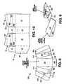
- FIG. 5is a photographic step-by-step illustration of the assembly of a bag-in-box beverage container of the present invention.
- FIG. 6is a photographic step-by-step illustration of the filling of a bag-in-box beverage container of the present invention.
- FIG. 7Ais a plan view for the blank of an alternative embodiment of an inner flow prompting ramp, for insertion into the outer shell for the bag-in-box beverage container of the present invention.
- FIG. 7Bis a view of the inner flow prompting ramp erected from the blank of FIG. 7A , as seen from underneath.
- FIG. 7Cis a view of the inner flow prompting ramp erected from the blank of FIG. 7A , as seen from above.
- FIG. 8is a plan view for the blank of an alternative embodiment of an inner flow prompting ramp, for insertion into the outer shell for the bag-in-box beverage container of the present invention.
- FIG. 9is a composite illustration of two perspective views of the ramp structure that is formed from the blank of FIG. 8 .
- FIG. 10is a plan view for the blank of an alternative embodiment of the invention, wherein the inner flow prompting ramp is integrally formed into the blank for the outer shell.
- FIG. 11is a perspective view of an outer shell according to the blank of FIG. 10 , wherein the inner flow prompting ramp is integrally formed into the blank for the outer shell.
- FIG. 12is a plan view of a blank for an outer shell according to an alternative embodiment of the invention, wherein spout apertures are provided on both front and sidewalls.
- FIG. 13is a plan view of a blank for an outer shell according to another alternative embodiment of the invention, wherein two spout apertures are provided on the front wall, so that, if desired, the outer shell may be inverted when in use.
- FIG. 14is a plan view for a blank for an inner flow prompting ramp, to be used in combination with the outer shell according to the blank of FIG. 13 .
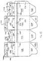
- FIG. 15is a plan view of a blank for another container, according to another embodiment of the invention, incorporating an opening mechanism.
- FIG. 16is a plan view of a blank for an internal spacer support structure, for use with the container formed from the blank of FIG. 15 .
- FIG. 17is a perspective view of a possible bag container, for use within the container formed from the blank of FIG. 15 .
- FIG. 18is an exploded perspective view of a closure device which may be used with the bag container of FIG. 17 .
- FIG. 19is an assembled perspective view of the closure device of FIG. 18 .
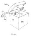
- FIG. 20is a perspective view of a container formed from the blank of FIG. 15 .
- FIG. 21is a perspective view of the container of FIG. 20 , shown with the opening mechanism partially deployed.
- FIG. 22is a perspective view of the container of FIG. 21 , shown with the opening mechanism more fully deployed.
- each of the blanks illustrated herein, in FIGS. 1-4are fabricated from corrugated paperboard material, although similar paper-based materials, having similar performance characteristics, may be employed if desired.
- Blank 10for the outer shell for the bag-in-box of the present invention is illustrated in FIG. 1 .
- Blank 10includes front wall 12 ; front bottom flap 14 ; and top handle flap 16 , which in turn includes panels 18 and 20 .
- Spout aperture 22is defined by cut flaps 24 a - 24 h and central aperture 26 .
- Blank 10also includes first sidewall 28 (foldably connected to front wall 12 ); sidewall bottom flap 30 with scored tabs 32 , 34 ; and first sidewall handle flap 36 , including panels 38 , 40 , with slots 42 , 44 , and notches 46 , 48 , and die cut push out flap 50 .
- Rear panel 52is foldably connected to first sidewall 28 .
- Rear bottom flap 54emanates from rear panel 52 , as does rear handle flap 56 , which includes, in turn, panels 58 and 60 .
- Frangibly attached to panel 60are foldably connected spout locking tabs 62 , 64 , each having keyhole shaped apertures therein.
- Second sidewall 66is foldably connected to rear panel 52 .
- Second sidewall bottom flap 68emanates from second sidewall 66 , and includes foldably connected tabs 70 , 72 .
- Second sidewall handle flap 74includes panels 76 , 78 , slots 80 , 82 , notches 84 , 86 and opening 88 .
- Glue flap 90is provided, which is affixed to an outside or inside surface of front panel 12 .
- first sidewall bottom flap 30 , rear bottom flap 54 and second sidewall bottom flap 68are folded inwardly, and upwardly of the bottom edges of front wall 12 , first sidewall 28 , rear wall 52 and second sidewall 66 .
- Tabs 72 and 34are glued to adjacent panels 54 and 14 , respectively.
- opposing flaps 68 and 30are interlocked at the notches formed between tabs 32 , 34 and 20 , 72 , respectively.
- Tabs 32 , 70are on the “inside” facing the interior of the resulting shell structure. See also sub FIGS. 3 and 4 of FIG. 5 .
- an inner flow prompting rampis formed from blank 100 (see FIG. 2 ).
- Blank 100includes inclined panel 102 , short front panel 104 (which has a height approximately equal to the distance between the bottom edge of front panel 12 and the lower periphery of spout aperture 22 , tall rear panel 106 , and trapezoidal side panels 108 , 110 , all of which will be folded to be parallel to respective front wall 12 , rear wall 52 , and first and second sidewalls 28 and 66 , respectively, upon insertion of the inner flow prompting ramp into the top opening of the shell (see FIGS. 5-5 and 5 - 6 ).
- Finger notch 112is provided, to facilitate removal and/or replacement of the inner flow prompting ramp formed from blank 100 , during assembly and knockdown of the beverage container.
- the inner containment bag/closure assemblywhich may be of any suitable design, is prepared for insertion into the outer shell.
- the bag/closure assemblywill be formed as a polyethylene (or other suitable food-grade plastic material) bag, at one end of which is attached an outwardly-threaded male spout member, which will typically have two axially spaced apart radially extending collars or rings, each of which is small in diameter than the large diameter portion of the keyhole openings of spout locking tabs 62 , 64 , but which is greater in diameter to the smaller diameter portion of the keyhole openings.
- a dust capis threaded onto the spout member to prevent contamination of the interior of the bag during shipping and storage.
- the bag/closure assemblyis prepared by removing the dust cap, expanding or “fluffing” the bag by pulling apart the (typically) folded over bag portion.
- FIG. 5-7The spout locking tabs 62 , 64 are pulled from panel 60 , and separated from each other.
- tabs 62 , 64is then placed over the male spout member to a position between the bag and the collar closest to the bag, and slid to one side, so that the smaller diameter portion of the keyhole aperture surrounds the spout, and the collar prevents removal of the spout from the collar.
- FIG. 5-8The bag/spout assembly is then placed inside the outer shell, and the spout is pushed through the aperture 22 .
- FIG. 5-9The collar farthest from the bag will momentarily displace tabs 24 a - 24 h , as the spout member passes through aperture 22 , with tabs 24 a - 24 h then flipping back down to approximately their original positions, behind the outer collar.
- the outer shellis then closed by folding panels 38 , 76 inwardly and down into the top opening of the outer shell, while folding panels 40 and 78 upwardly. Panels 40 and 78 will be juxtaposed parallel to and against one another, in a vertical orientation. FIGS. 5-11 through 5 - 13 . Then, panels 18 and 58 are folded inwardly over the top of the outer shell, to positions coplanar to each other and parallel to the bottom of the outer shell. Panels 20 and 60 are then folded down to positions parallel to each other and to front wall 12 . Notch 120 will interdigitate with notches 48 and 84 which will be aligned with one another, while hooked tabs 122 and 124 will be inserted into and engage slots 44 and 80 , respectively.
- Notch 130will interdigitate with notches 46 and 86 , while hooked tabs 132 , 134 will be inserted into and engage slots 82 , 42 , respectively.
- Panel 50is then pushed through the opening 88 of adjacent panel 78 , and folded upward, during carrying, to help hold panels 40 , 78 together.
- the hooked tabsThrough the use of the hooked tabs, the handle is firmly locked into place, and will be unlikely to spontaneously dislodge or disassemble, during normal use and loading conditions, in the absence of affirmative, intentional dismantling of the container.
- the bag-in-box beverage containermay be stored, upon returning the dust cap to its position screwed onto the male spout member. Filling of the container is demonstrated in FIGS. 6-1 through 6 - 4 . Once filling has been accomplished, then a female cap, provided with a positive closing tap (which may be of any suitable configuration) is screwed onto the male spout member, the container is uprighted, and rendered ready for dispensing.
- the bag-in-box beverage containeris broken down for disposal and recycling essentially by reversing the foregoing procedure.
- FIG. 3illustrates a blank for an alternative embodiment of the flow prompting structure.
- An inner flow prompting rampis formed from blank 200 .
- Blank 200includes inclined panel 202 , short front panel 204 (which has a height approximately equal to the distance between the bottom edge of front panel 12 and the lower periphery of spout aperture 22 ; tall rear panel 206 ; and trapezoidal side panels 208 , 210 , all of which will be folded to be parallel to respective front wall 12 , rear wall 52 , and first and second sidewalls 28 and 66 , respectively, upon insertion of the inner flow prompting ramp into the top opening of the shell.
- Finger notch 212is provided, to facilitate removal and/or replacement of the inner flow prompting ramp formed from blank 200 , during assembly and knockdown of the beverage container.
- Blank 200also includes reinforcing corner panels 214 , 216 , 218 and 220 .
- FIG. 4illustrates a blank for an alternative embodiment of the flow prompting structure.
- An inner flow prompting rampis formed from blank 300 .
- Blank 300includes inclined panel 302 , short front panel 304 (which has a height approximately equal to the distance between the bottom edge of front panel 12 and the lower periphery of spout aperture 22 ; tall rear panel 306 ; and trapezoidal side panels 308 , 310 , all of which will be folded to be parallel to respective front wall 12 , rear wall 52 , and first and second sidewalls 28 and 66 , respectively, upon insertion of the inner flow prompting ramp into the top opening of the shell.
- Finger notch 312is provided, to facilitate removal and/or replacement of the inner flow prompting ramp formed from blank 300 , during assembly and knockdown of the beverage container.
- Blank 300also includes bottom panels 314 , 316 , which will be folded into interlocking relation to one another underneath inclined panel 302 , via notches 318 , 320 .
- the bag-in-box beverage container of the present inventionis believed to embody a number of advantages over prior art containers, even including prior art corrugated containers, such as facilitated assembly and readiness; facilitated filling of the internal bag; facilitated handling and delivery, via the recessed and locked-in-place handle; easy knock-down for recycling; the ability to employ a wide variety of existing taps and spigots; the provision of a level, flat top profile to permit stacking of stored containers, and even limited stacking of filled containers.
- FIG. 7Ais a plan view for the blank of an alternative embodiment of an inner flow prompting ramp, for insertion into the outer shell for the bag-in-box beverage container of the present invention, seen from above in FIG. 7C .
- Blank 400includes inclined panel 402 ; front panel 404 ; rear panel 406 ; side panels 408 , 410 ; die cut grasping aperture 412 ; and gusset panel pairs 414 , 416 ; 418 , 420 ; 422 , 424 ; 426 , 428 .
- FIG. 8is a plan view for the blank of an alternative embodiment of an inner flow prompting ramp, for insertion into the outer shell for the bag-in-box beverage container of the present invention.
- Blank 500comprises inclined panel 502 ; rear panel 504 ; side panels 506 , 508 ; bottom panels 510 , 512 with cell flaps 514 , 516 ; center support panels 518 , 520 ; and inside inclined panels 526 , 528 .
- the panels at the ends of blank 500are successively folded inwardly (panels 528 , 526 folded perpendicular to panels 518 , 520 ; panels 518 , 520 are folded perpendicular to panels 510 , 512 ; panels 510 , 512 are folded perpendicular to panels 506 , 508 ; and finally panels 506 , 508 are folded perpendicular to panel 502 , so that panels 526 , 528 eventually are positioned underneath panel 502 , in juxtaposed underlying parallel relationship thereto.
- T-shaped tab 522is pushed out and folded over and pushed into aperture 524 , to lock the ramp into its articulated configuration, as shown in FIG.
- FIG. 9which is a composite illustration of two perspective views of the ramp structure that is formed from the blank 500 of FIG. 8 .
- Cell flaps 514 , 516are pivotable to enable the storage within the ramp of articles, such as measuring cups or the like.
- rear panel 504may be folded downwardly to cover the ends of the wedge-shaped enclosed areas at the end of the ramp, or folded upwardly (both as shown in FIG. 9 ).
- FIG. 10is an outside plan view of a portion of the blank 10 ′ of an alternative embodiment of the invention, wherein the inner flow prompting ramp is integrally formed into the blank for the outer shell.
- panels 14 , 30 , 54 and 68may be replaced, respectively, by panels 14 ′, 30 ′ 54 ′ and 68 ′.
- Panels 30 ′ and 68 ′are, in turn, formed by bottom panels 30 a ′, 68 a ′; inside support panels 30 b ′, 68 b ′; inclined panels 30 c ′, 68 c ′; and outside support panels 30 d ′, 68 d ′.
- blank 10 ′preferably may be substantially the same as blank 10 in configuration, with respect to the top end closing and handle structures, and with respect to the spout aperture.
- FIG. 12illustrates a blank 600 for an outer shell according to an alternative embodiment, wherein the front wall 602 is now located between the sidewalls 604 , 606 , instead of at the end of the blank, as in the embodiment of FIG. 1 , and rear wall 608 is now at the end of the blank, instead of being between the sidewalls as in the embodiment of FIG. 1 .
- a spout aperture 610is located on sidewall 604 , as well as spout aperture 612 on front wall 602 , so that a choice is given as to the location of the spout, and indeed the orientation of the outer shell.
- the remaining panels and flaps at the top and bottom of the blankare, as can be seen in a comparison of FIGS.
- FIG. 12essentially identical in structure and operation. Accordingly, the same method of formation of the top and bottom closures, as described with respect to the embodiment of FIG. 1 , applies to the embodiment of FIG. 12 .
- Slightly different spout locking pieces 614 , 616are provided, which emanate from one of the sidewall top flap panels. Locking pieces 614 , 616 are not slipped over the spout, but instead are simply slipped in place from the side, relying upon orientation and friction to be maintained in place during use.
- Aperture 610permits the container formed from blank 600 to be inverted or laid on its side (depending upon the size, shape and orientation of the inner flow prompting ramp within the outer shell).
- the outer shellwill be inverted, to enable use of aperture 610 .
- the outer shellwill be laid on its side (i.e., on rear wall 608 ), to permit dispensing from aperture 610 .
- FIG. 13illustrates a blank 700 for an outer shell according to another alternative embodiment of the invention, having sidewall 702 , front wall 706 , rear wall 704 , and other sidewall 708 .
- Two apertures 710 and 712are provided at the top center and bottom center of sidewall 702 .
- Slightly different spout locking pieces 714 , 716are provided, which emanate from one of the sidewall top flap panels. Locking pieces 714 , 716 are not slipped over the spout, but instead are simply slipped in place from the side, relying upon orientation and friction to be maintained in place during use.
- the remaining panels and flaps at the top and bottom of the blankare, as can be seen in a comparison of FIGS. 1 and 13 , essentially identical in structure and operation. Accordingly, the same method of formation of the top and bottom closures, as described with respect to the embodiment of FIG. 1 , applies to the embodiment of FIG. 13 .
- FIG. 14illustrates blank 800 for an alternative embodiment of an inner flow prompting ramp, for use with blank 700 of FIG. 13 , wherein use of the sidewall apertures is desired.
- Blank 800provides for the sloping of the top panel of the ramp from one long edge to the other (i.e., from side to side, instead of front to back).
- FIGS. 15-22Such an alternative embodiment of the invention is illustrated in FIGS. 15-22 .
- FIG. 15is a plan view of a blank for the container, which incorporates an opening mechanism, to enable a top portion of the outer container to be removed, to provide ready access to the liquid impermeable bag contained within.
- Blank 1000is preferably fabricated from paper, paperboard and/or corrugated paperboard material, preferably corrugated paperboard.
- Blank 1000includes front panel 1002 ; front bottom flap 1004 , with foldably connected tab 1005 ; and top handle flap 1006 , which in turn includes panels 1008 and 1010 .
- Panel 1008includes slots 1012 and 1014
- panel 1010includes notches 1016 , 1018 , and die-cut finger opening 1020 .
- Side panel 1022is foldably connected to front panel 1002 , and has emanating therefrom side panel bottom flap 1024 ; and side panel top flap 1026 , which in turn, comprises panels 1028 , 1030 , with notch 1032 , and hooked tabs 1034 , 1036 .
- Rear panel 1038is foldably connected to side panel 1022 .
- Rear bottom flap 1040emanates from rear panel 1038 (and includes foldably connected tab 1042 ), as does rear handle flap 1044 , which includes, in turn, panels 1046 , 1048 .
- Panel 1046includes slots 1050 and 1052
- panel 1048includes notches 1054 , 1056 , and die-cut finger opening 1058 .
- second side panel 1060is also foldably connected to front panel 1002 , from which foldably emanate bottom panel 1062 , and second side panel flap 1064 , including panels 1066 , 1068 , with notch 1070 , and hooked tabs 1072 , 1074 .
- Glue flap 1076emanates from a side edge of second side panel 1060 .
- Opening structure 1078includes lines of weakness (e.g., two zipper-cut strips 1080 , 1082 ), disposed in panels 1002 , 1022 and 1060 , respectively (and terminating in two pull tabs 1084 , 1086 , respectively).
- the ends of zipper-cut strips 1080 , 1082 distal to pull tabs 1084 , 1086are connected by a further line of weakness, e.g., a lines of perforations 1088 .
- Glue flap 1076also includes a line of weakness, e.g., a line of perforations 1090 .
- the two discrete zipper cut stripsmay be replaced with a single zipper strip or other line of weakness. Further, the line of perforations may extend across more than one side panel; or alternatively, the zipper cut strip(s) may extend around the entire circumference of the container, depending upon the loading which the container will be expected to encounter and withstand.
- glue flap 1076is preferably adhered to an inside surface of panel 1038 .
- Tab 1042is adhered to panel 1024 and tab 1005 is adhered to panel 1062 , to form an automatically deploying carton bottom, the structure and operation of which are well known to those of ordinary skill in the art.
- Such an automatically deploying bottompermits the folded and glued carton to be folded flat, with the several bottom panels being folded upwardly inside the carton cavity.
- the bottom panelsare constrained to fold downwardly, proximately perpendicular to the front, rear and side panels, to form the bottom of the container.
- FIG. 16is a plan view of a blank for an internal spacer support structure, for use with the container formed from the blank of FIG. 15 .
- Spacer support structure blank 1100includes panels 1102 , 1104 , 1106 , 1108 , 1110 , 1112 , 1114 , 1116 , 1118 , die-cut tab 1120 and slot 1122 .
- spacer support structure blank 1100When spacer support structure blank 1100 is folded upon itself, and tab 1120 is inserted into slot 1122 , the resulting structure is a tubular structure, which is intended to be inserted downwardly, through the top opening of an unflattened, deployed container formed from blank 1000 , to the bottom of the container, with panel 1110 preferably facing up toward the opening of the container, to create an air space or “air cell” in the bottom portion of the formed container, for the bag to rest upon.
- the purpose of the air space or air cellis to provide an insulating layer, as well as a cushioned support, for the interior bag, which contains the semi-solid material (such as soup).
- the form and structure of the bagmay be of any suitable shape, material and configuration, as desired or required by the needs of the particular application.
- One potential style of bag that may be usedmay be a simple open-topped, block-bottomed bag using closure structures marketed and sold under the brand name Clip-n-Seal®, by Texturadesign of Seattle, Wash.
- Such a bag 1200 with such a closureis shown in FIGS. 17-19 herein.
- the closureoperates by capturing the flattened end of the bag between components 1202 and 1204 , which snap together around the flattened bag end.
- FIG. 20is a perspective view of a container formed from the blank of FIG. 15 . Closure of the top of container 1300 (formed from blank 1000 ) is accomplished by first folding panels 1008 , 1046 inwardly, with panels 1008 and 1046 extending inwardly and downwardly, and panels 1010 , 1048 overlying one another and extending vertically.
- Panels 1026 , 1064are then folded toward one another, until panels 1028 , 1066 are extending perpendicular to side panels 1022 , 1060 , and panel 1030 , 1068 are folded downwardly, until notches 1032 , 1070 interdigitate with notches 1016 , 1056 and 1054 , 1018 , and hooked tabs 1034 , 1074 , 1036 , 1072 are received within slots 1012 , 1050 , 1052 , 1014 , respectively.
- FIG. 21is a perspective view of the container of FIG. 15 , shown with the opening mechanism partially deployed, through pull tabs 1084 , 1086 being pulled away from panel 1002 , and zipper strips 1082 , 1080 being pulled away, separating the top portions of panels 1002 , 1060 , 1022 , away from their respective bottom portions.
- zipper strips 1080 , 1082have been pulled to their limits, as seen in FIG. 22 , to perforation line 1088
- complete removal of the handle portion of carton 1300is accomplished by tearing the top portion from the bottom portion along perforation line 1088 .
- complete access to the bag(not shown in FIGS. 20-22 ) is provided.
- the bagmay then be opened, and the contents removed, e.g., by ladle.
Landscapes
- Engineering & Computer Science (AREA)
- Mechanical Engineering (AREA)
- Cartons (AREA)
- Packages (AREA)
Abstract
Description
Claims (13)
Priority Applications (3)
| Application Number | Priority Date | Filing Date | Title |
|---|---|---|---|
| US10/955,702US7389909B2 (en) | 2002-11-13 | 2004-09-30 | Bag-in-box container |
| CA 2521341CA2521341A1 (en) | 2004-09-30 | 2005-09-27 | Bag-in-box container |
| MXPA05010526MXPA05010526A (en) | 2004-09-30 | 2005-09-29 | Bag-in-box container. |
Applications Claiming Priority (2)
| Application Number | Priority Date | Filing Date | Title |
|---|---|---|---|
| US10/293,878US7007825B2 (en) | 2002-11-13 | 2002-11-13 | Bag-in-box beverage container |
| US10/955,702US7389909B2 (en) | 2002-11-13 | 2004-09-30 | Bag-in-box container |
Related Parent Applications (1)
| Application Number | Title | Priority Date | Filing Date |
|---|---|---|---|
| US10/293,878ContinuationUS7007825B2 (en) | 2002-11-13 | 2002-11-13 | Bag-in-box beverage container |
Publications (2)
| Publication Number | Publication Date |
|---|---|
| US20050051573A1 US20050051573A1 (en) | 2005-03-10 |
| US7389909B2true US7389909B2 (en) | 2008-06-24 |
Family
ID=32229745
Family Applications (2)
| Application Number | Title | Priority Date | Filing Date |
|---|---|---|---|
| US10/293,878Expired - Fee RelatedUS7007825B2 (en) | 2002-11-13 | 2002-11-13 | Bag-in-box beverage container |
| US10/955,702Expired - Fee RelatedUS7389909B2 (en) | 2002-11-13 | 2004-09-30 | Bag-in-box container |
Family Applications Before (1)
| Application Number | Title | Priority Date | Filing Date |
|---|---|---|---|
| US10/293,878Expired - Fee RelatedUS7007825B2 (en) | 2002-11-13 | 2002-11-13 | Bag-in-box beverage container |
Country Status (3)
| Country | Link |
|---|---|
| US (2) | US7007825B2 (en) |
| CA (1) | CA2449330C (en) |
| MX (1) | MXPA03010358A (en) |
Cited By (24)
| Publication number | Priority date | Publication date | Assignee | Title |
|---|---|---|---|---|
| US20060097005A1 (en)* | 2002-11-13 | 2006-05-11 | Smurfit-Stone Container Enterprises, Inc. | Bag-in-box beverage container |
| US20080023533A1 (en)* | 2006-07-26 | 2008-01-31 | Benq Corporation | Packing box and fabricating board thereof |
| US20090283554A1 (en)* | 2008-05-19 | 2009-11-19 | Jason Morgan Kelly | Regulated fluid dispensing device and method of dispensing a carbonated beverage |
| US20090283540A1 (en)* | 2008-05-19 | 2009-11-19 | Jason Morgan Kelly | Regulated fluid dispensing device and method of dispensing a carbonated beverage |
| US20090283553A1 (en)* | 2008-05-19 | 2009-11-19 | Vong Hoss | Modular constructed regulated fluid dispensing device |
| US20090283579A1 (en)* | 2008-05-19 | 2009-11-19 | Kelly Jason M | Regulated fluid dispensing system packaging |
| USD604606S1 (en)* | 2008-05-30 | 2009-11-24 | Gringo Ventures, LLC | Floral delivery box with removable upper portion |
| USD625600S1 (en) | 2010-01-25 | 2010-10-19 | OTB Packaging, Inc. | Beverage container |
| US20110111938A1 (en)* | 2009-11-11 | 2011-05-12 | Kenneth Charles Smith | Liquid dispensing containers and blanks for making the same |
| US8646679B2 (en) | 2010-04-16 | 2014-02-11 | Webb LeRon Hill | Security collar for beverage container |
| US8720769B2 (en) | 2009-09-15 | 2014-05-13 | Packaging Corporation Of America | Beverage container |
| US8746541B2 (en) | 2005-03-04 | 2014-06-10 | Graphic Packaging International, Inc. | Bag-in-a-box |
| US20140356488A1 (en)* | 2012-02-02 | 2014-12-04 | Rachel Dadush | Container for dry goods |
| USD727458S1 (en) | 2014-06-03 | 2015-04-21 | Marlido, LLC | Portable water supply |
| USD729342S1 (en) | 2014-06-03 | 2015-05-12 | Marlido, LLC | Portable water supply |
| USD729341S1 (en) | 2014-06-03 | 2015-05-12 | Marlido, LLC | Portable water supply |
| US9162801B2 (en)* | 2012-07-11 | 2015-10-20 | Bolso, Llc | Product container |
| US9428326B2 (en) | 2014-06-03 | 2016-08-30 | Marlido, LLC | Portable water supply |
| US20160318655A1 (en)* | 2015-04-28 | 2016-11-03 | Magic Packing Enterprise Co., Ltd. | Easy Open Carton |
| US9708113B1 (en) | 2014-06-03 | 2017-07-18 | Marlido, LLC | Portable water supply |
| US20200255204A1 (en)* | 2018-04-16 | 2020-08-13 | International Paper Company | Sioc bag-in-box |
| US10919680B1 (en) | 2018-10-08 | 2021-02-16 | Packaging Corporation Of America | Liquid beverage container |
| USD980069S1 (en) | 2020-07-14 | 2023-03-07 | Ball Corporation | Metallic dispensing lid |
| US12168551B2 (en) | 2021-03-01 | 2024-12-17 | Ball Corporation | Metal container and end closure with seal |
Families Citing this family (44)
| Publication number | Priority date | Publication date | Assignee | Title |
|---|---|---|---|---|
| US6443329B1 (en)* | 2002-01-10 | 2002-09-03 | Stone Container Corporation | Corrugated hanging dispenser |
| US7007825B2 (en)* | 2002-11-13 | 2006-03-07 | Smurfit-Stone Container Enterprises, Inc. | Bag-in-box beverage container |
| US7254848B2 (en)* | 2004-04-01 | 2007-08-14 | Encon Safety Products, Inc. | Emergency eye wash system |
| US8413801B2 (en)* | 2005-06-01 | 2013-04-09 | International Paper Company | Lidded container with a tear strip |
| US8459449B2 (en)* | 2005-06-01 | 2013-06-11 | International Paper Company | Easy-opening carton for shipping and storing cut paper |
| US20070045339A1 (en)* | 2005-08-27 | 2007-03-01 | Manion Randolph T | Beverage dispensing box for office and kitchen counters |
| GB0524789D0 (en) | 2005-12-05 | 2006-01-11 | Myerscough Martin | Container |
| US8905267B2 (en)* | 2005-12-12 | 2014-12-09 | Carrier Corporation | Concentrate holder |
| US20080067200A1 (en)* | 2006-09-18 | 2008-03-20 | Arnon Bernshtein | Spare wheel cover |
| NL2000414C2 (en)* | 2007-01-03 | 2008-07-04 | 4Sight Innovation Bv | Packaging for food i.e. beverage such as fruit juice, has box-shaped container comprising flexible bag for containing food, where flexible bag comprises rigid closure for closing box-shaped container |
| US9027826B2 (en)* | 2007-05-02 | 2015-05-12 | Watson Laboratories, Inc. | Frangible shipping carton and associated methods |
| CA2898211C (en) | 2007-05-11 | 2018-01-02 | Lawrence Dull | Systems, components, and methods for delivering liquid substances |
| WO2008146240A2 (en)* | 2007-05-30 | 2008-12-04 | Koninklijke Philips Electronics N.V. | Paper-based beer container and dispensing apparatus therefor |
| US8939351B2 (en)* | 2007-10-18 | 2015-01-27 | Rock-Tenn Shared Services, Llc | Bag-in-box container and method of constructing the same |
| US20090283541A1 (en)* | 2008-05-14 | 2009-11-19 | Sealed Air Corporation | System and apparatus for dispensing pumpable products |
| USD617635S1 (en)* | 2008-10-22 | 2010-06-15 | Direct Dimensional Design | Coffee box cover |
| US20100116824A1 (en)* | 2008-11-07 | 2010-05-13 | Stalions Stephen E | Bag-in-box assembly |
| USD602778S1 (en) | 2008-11-07 | 2009-10-27 | Rieke Corporation | Fitment for a container |
| USD606863S1 (en) | 2008-11-07 | 2009-12-29 | Rieke Corporation | Fitment for a container, as installed in a plastic bag |
| US8276806B2 (en)* | 2008-11-21 | 2012-10-02 | Graphic Packaging International, Inc. | Carton for flowable material |
| TWM369718U (en)* | 2009-07-17 | 2009-12-01 | Pegatron Corp | Disposable tea set and tea pot thereof |
| USD633787S1 (en)* | 2009-07-31 | 2011-03-08 | The Procter & Gamble Company | Carton |
| US8408790B2 (en)* | 2009-10-15 | 2013-04-02 | Bill Reilly | Liquid package and uses thereof |
| USD617185S1 (en)* | 2009-11-18 | 2010-06-08 | Conopco, Inc. | Packaging |
| US8857642B2 (en)* | 2010-05-05 | 2014-10-14 | Pandol Bros., Inc. | Lightweight fruit and produce packaging container |
| GB201015604D0 (en)* | 2010-09-17 | 2010-10-27 | Ds Smith Packaging Ltd | Carton and a blank therefor |
| DE202010015028U1 (en)* | 2010-11-05 | 2012-02-06 | A&R Carton Bremen Gmbh | folding |
| US9415997B2 (en)* | 2012-04-26 | 2016-08-16 | Southern Champion Tray | Bottle in box container |
| KR20140064894A (en) | 2011-08-22 | 2014-05-28 | 어드밴스드 테크놀러지 머티리얼즈, 인코포레이티드 | Substantially rigid collapsible container with fold pattern |
| US9415990B2 (en)* | 2013-02-13 | 2016-08-16 | Cryovac, Inc. | Bag-in-box system for use in dispensing a pumpable product |
| US20140290181A1 (en)* | 2013-04-01 | 2014-10-02 | Bottle Tree Water Corporation | System and Method for Eco-Friendly Beverage Dispensing Kiosk |
| US9796499B2 (en)* | 2013-04-30 | 2017-10-24 | Tidi Products, Llc | Eye shield and frames dispenser |
| GB2531013A (en)* | 2014-10-07 | 2016-04-13 | Frugalpac Ltd | Container |
| US9751656B2 (en)* | 2015-02-27 | 2017-09-05 | Lbp Manufacturing Llc | Beverage container |
| CN106184964B (en)* | 2015-05-06 | 2019-01-15 | 崎碁包装实业有限公司 | Easy-to-tear paper box |
| CA2952085C (en)* | 2015-05-29 | 2022-11-29 | Lbi Brands, Inc. | Water box apparatus and method |
| US10829280B2 (en)* | 2015-12-03 | 2020-11-10 | Drop Water Corporation | Compostable single-use beverage container and associated mechanism for sealing the container |
| CA3046657A1 (en)* | 2016-12-15 | 2018-06-21 | Westrock Shared Services, Llc | Bag-in-box packaging |
| US20180370203A1 (en)* | 2017-06-23 | 2018-12-27 | Jeanine Longo | Storage of Beauty Products in a Carton |
| US11186405B2 (en)* | 2017-08-02 | 2021-11-30 | David T. Hengami | Folding box with integral product holder |
| EP4095054A1 (en)* | 2020-05-08 | 2022-11-30 | The Procter & Gamble Company | Detergent product container with lock |
| IT202000031829A1 (en)* | 2020-12-22 | 2022-06-22 | Azionaria Costruzioni Macch Automatiche Acma S P A | DISPENSER PACKAGE FOR BULK ITEMS AND ASSEMBLY OF BLANKS TO MAKE A DISPENSER PACKAGE FOR BULK ITEMS |
| PL4071073T3 (en)* | 2021-04-06 | 2023-12-27 | Fameccanica.Data S.P.A. | CHILD-PROOF PAPER OR CARDBOARD CONTAINER |
| WO2025101796A1 (en)* | 2023-11-09 | 2025-05-15 | Revobox Dispensing Technologies, Llc | Prism shaped box, blank for forming same, and method of folding same |
Citations (10)
| Publication number | Priority date | Publication date | Assignee | Title |
|---|---|---|---|---|
| US2822118A (en)* | 1956-01-05 | 1958-02-04 | Fund Del Inc | Tear strip means for opening cartons and the like |
| US3134531A (en)* | 1962-10-16 | 1964-05-26 | Hardy Salt Company | Dispensing container |
| US3194480A (en)* | 1962-10-19 | 1965-07-13 | Lever Brothers Ltd | Collapsible pack with recessed handle |
| US3255950A (en)* | 1964-09-15 | 1966-06-14 | Lever Brothers Ltd | Pack with recessed handle |
| US5074460A (en)* | 1990-10-24 | 1991-12-24 | Hanekamp Matthew R | Container structure |
| US5105971A (en)* | 1991-09-17 | 1992-04-21 | American Packaging Corporation | Carton |
| US5584430A (en)* | 1996-03-15 | 1996-12-17 | Amway Corporation | Flip-top container with integral handles |
| US6196452B1 (en)* | 1995-09-26 | 2001-03-06 | Jared P. Andrews, Sr. | Beverage container |
| US6422454B1 (en)* | 2001-02-13 | 2002-07-23 | Kraft Foods, Inc. | Flip-top package for shipping and display of a multi-component meal kit |
| US7007825B2 (en)* | 2002-11-13 | 2006-03-07 | Smurfit-Stone Container Enterprises, Inc. | Bag-in-box beverage container |
Family Cites Families (69)
| Publication number | Priority date | Publication date | Assignee | Title |
|---|---|---|---|---|
| US181014A (en) | 1876-08-15 | Improvement in square cans | ||
| US3123254A (en) | 1964-03-03 | Liquid dispensing container | ||
| US1046945A (en) | 1911-12-14 | 1912-12-10 | Fred W Bauer | Paper box for liquids. |
| US1088964A (en) | 1913-01-31 | 1914-03-03 | Velanda B Carmean | Box for carrying and dispensing liquids. |
| US2574931A (en) | 1948-12-20 | 1951-11-13 | Stauffer Chemical Co | Container for corrosive fluids |
| US2618409A (en) | 1949-09-07 | 1952-11-18 | Eisenberger Sidney | Liquid container comprising a flexible envelope |
| US2831610A (en)* | 1956-09-13 | 1958-04-22 | Chase Bag Company | Liquid dispensing container |
| US2954901A (en) | 1956-10-29 | 1960-10-04 | Hedwin Corp | Composite package |
| US3054549A (en) | 1960-02-15 | 1962-09-18 | Albert E Reed And Company Ltd | Cases for containers |
| US3117695A (en) | 1960-05-19 | 1964-01-14 | Inland Container Corp | Fluid dispensing container |
| US3078018A (en) | 1960-08-18 | 1963-02-19 | Lawrence Paper Co | Dispensing container |
| US3081911A (en) | 1960-09-29 | 1963-03-19 | Scholle Container Corp | Drainage fitting for collapsible container |
| US3087655A (en) | 1961-01-30 | 1963-04-30 | Scholle Container Corp | Paperboard container with flexible liner therein |
| US3090526A (en) | 1961-04-20 | 1963-05-21 | Corrugated Container Company | Disposable-type dispensing container package |
| US3169690A (en) | 1961-10-20 | 1965-02-16 | Scholle Container Corp | Container |
| US3132789A (en) | 1961-10-25 | 1964-05-12 | Gerald V Forrest | Packaging containers |
| US3160326A (en) | 1961-12-04 | 1964-12-08 | Procter & Gamble | Composite package |
| US3143249A (en) | 1962-01-08 | 1964-08-04 | Stone Container Corp | Collapsible bulk fluid container |
| US3163544A (en) | 1962-03-06 | 1964-12-29 | Emery I Valyi | Container |
| US3119544A (en) | 1962-03-30 | 1964-01-28 | Procter & Gamble | Composite package |
| US3108732A (en) | 1962-09-13 | 1963-10-29 | Corrugated Container Company | Disposable type pouring container package combination |
| US3173579A (en) | 1964-03-04 | 1965-03-16 | Corrugated Container Company | Disposable type dispensing container package |
| US3226002A (en) | 1963-04-22 | 1965-12-28 | James W Walker | Flexible container, fitting therefor, and composite package |
| US3221943A (en) | 1963-10-16 | 1965-12-07 | George C Anderson | Container with valve operated nozzle |
| US3233817A (en) | 1964-02-24 | 1966-02-08 | Stone Container Corp | Paperboard package with plastic bag insert for storage and shipping of fluids |
| US3227322A (en) | 1964-04-06 | 1966-01-04 | Robert E Crain | Material dispensing container |
| US3363807A (en) | 1965-01-22 | 1968-01-16 | Howard P. Powell | Flexible dispensing bag and semirigid container therefor |
| US3427646A (en) | 1965-02-05 | 1969-02-11 | Scholle Container Corp | Container opening,filling and closing apparatus |
| GB1098401A (en) | 1965-03-26 | 1968-01-10 | Reed Paper Group Ltd | Improvements in or relating to packs for collapsible bottles and like containers |
| US3439757A (en)* | 1968-03-12 | 1969-04-22 | Wayland D Elenburg | Drilling apparatus |
| US3952940A (en) | 1972-06-26 | 1976-04-27 | Flag Carton Corporation Ltd. | Paperboard cartons with liquid-proof liners |
| US3931916A (en) | 1974-08-15 | 1976-01-13 | Slip-Not Corporation | Dispensing-type box |
| GB1529062A (en) | 1976-07-28 | 1978-10-18 | Ici Ltd | Method of packaging powders and pastes |
| US4174051A (en) | 1978-07-26 | 1979-11-13 | The Continental Group, Inc. | Protective locking flaps for opening in sealed corrugated containers |
| DE2908654A1 (en) | 1979-03-06 | 1980-09-11 | Rupert Mader | Dispensing pack for wine - has collapsible plastic foil bag witb closable outlet tube in rigid container with opening for tube |
| US4375864A (en) | 1980-07-21 | 1983-03-08 | Scholle Corporation | Container for holding and dispensing fluid |
| DE3336269A1 (en) | 1983-10-05 | 1985-04-18 | Carl Edelmann Gmbh, 7920 Heidenheim | INTERNAL BAG PACK WITH LOCKABLE POURING PIPE |
| US4653671A (en) | 1984-01-09 | 1987-03-31 | Christene Duffy | Container |
| GB2172663A (en) | 1985-03-20 | 1986-09-24 | Bxl Plastics Ltd | Liquid containers |
| ES2023857B3 (en) | 1985-11-19 | 1992-02-16 | Carl Edelmann Verpackungstechnik Gmbh | TRANSPORTATION AND RESERVE DEPOSITS FOR CONCENTRATED DRINKS OR LIKE |
| GB2188305A (en) | 1986-03-25 | 1987-09-30 | Derrick Raymond Gatley | Lined containers for liquids |
| US4673125A (en)* | 1986-06-23 | 1987-06-16 | Container Corporation Of America | Dispensing container |
| US4850509A (en) | 1987-03-13 | 1989-07-25 | Hollenberg Dennis D | Quickly erectable containers |
| US4781314A (en) | 1987-03-30 | 1988-11-01 | Schoonover Michael I | Fluid container |
| US4815631A (en) | 1988-03-10 | 1989-03-28 | S. C. Johnson & Son, Inc. | Bag-in-box package |
| US5125566A (en) | 1989-02-10 | 1992-06-30 | Deiger Anthony J | Dispensing container with modified corner structure |
| DE3915899A1 (en) | 1989-05-16 | 1990-11-22 | Edelmann Carl Gmbh | CARDBOARD PACKAGING CONTAINER WITH INTERNAL BAG TO RECEIVE LIQUIDS |
| GB8920336D0 (en) | 1989-09-08 | 1989-10-25 | Reed Packaging Ltd | Carton and blank for making the same |
| US5050775A (en) | 1989-10-31 | 1991-09-24 | International Paper Company | Beverage dispenser and cup holder |
| US4934654A (en) | 1989-11-09 | 1990-06-19 | Shippers Paper Products Company | Valve for bulk container |
| DE4000652C1 (en) | 1990-01-11 | 1991-07-18 | Sotralentz S.A., Drulingen, Bas-Rhin, Fr | |
| DE9000528U1 (en) | 1990-01-18 | 1990-03-22 | Carl Edelmann Verpackungstechnik GmbH, 7920 Heidenheim | Inner bag packing |
| CA2015175A1 (en)* | 1990-04-23 | 1991-10-23 | Donald A. Brown | Method and apparatus for dispensing flowable hair products |
| US5037002A (en) | 1990-07-11 | 1991-08-06 | Liqui-Box/B-Bar-B Corporation | Integral self-supporting and recyclable liquid container |
| GB2246764B (en) | 1990-08-07 | 1994-05-18 | Anthony David Shaw | A drinks box dispenser for dispensing drinks held in a container within the dispenser |
| US5265766A (en) | 1990-11-09 | 1993-11-30 | Jacobs Suchard Ag | Apparatus for receiving and dispensing liquids |
| US5156295A (en) | 1991-01-28 | 1992-10-20 | International Paper Company | Bag lined carton with pour spout |
| US5042682A (en) | 1991-03-05 | 1991-08-27 | Container Corporation Of America | Outer container for composite dispensing package |
| EP0513495B1 (en) | 1991-03-19 | 1995-02-15 | Toppan Printing Co., Ltd. | Liquid container |
| US5147071A (en) | 1991-04-09 | 1992-09-15 | The Coca-Cola Company | Collapsible bag with evacuation passageway and method for making the same |
| CA2181269A1 (en) | 1994-11-16 | 1996-05-23 | Robin David Eliovson | Fluid containers and methods of manufacture thereof |
| US5826752A (en)* | 1995-05-23 | 1998-10-27 | Latimer; Scott | Fluid despensing and shipping container system and methods |
| US6062431A (en) | 1998-06-08 | 2000-05-16 | Bib Pak, Inc. | Package for beverages |
| US6053401A (en) | 1998-06-26 | 2000-04-25 | J & M Coffee Container Company, Inc. | Beverage container |
| WO2001026985A1 (en) | 1999-10-08 | 2001-04-19 | Lloyd James J | Portable beverage delivery system |
| US6827237B2 (en) | 2000-04-13 | 2004-12-07 | Dr Pepper/Seven-Up, Inc. | Bag-in-box container for liquids |
| US6755324B2 (en) | 2002-04-29 | 2004-06-29 | Bib Pak, Inc. | Transporting/dispensing package for plural beverages |
| US6736289B2 (en)* | 2002-05-17 | 2004-05-18 | Lbp Manufacturing, Inc. | Bulk container assembly |
| US7077309B2 (en) | 2002-07-24 | 2006-07-18 | J & M Coffee Container Company, Inc. | Beverage container |
- 2002
- 2002-11-13USUS10/293,878patent/US7007825B2/ennot_activeExpired - Fee Related
- 2003
- 2003-11-13CACA002449330Apatent/CA2449330C/ennot_activeExpired - Fee Related
- 2003-11-13MXMXPA03010358Apatent/MXPA03010358A/enactiveIP Right Grant
- 2004
- 2004-09-30USUS10/955,702patent/US7389909B2/ennot_activeExpired - Fee Related
Patent Citations (10)
| Publication number | Priority date | Publication date | Assignee | Title |
|---|---|---|---|---|
| US2822118A (en)* | 1956-01-05 | 1958-02-04 | Fund Del Inc | Tear strip means for opening cartons and the like |
| US3134531A (en)* | 1962-10-16 | 1964-05-26 | Hardy Salt Company | Dispensing container |
| US3194480A (en)* | 1962-10-19 | 1965-07-13 | Lever Brothers Ltd | Collapsible pack with recessed handle |
| US3255950A (en)* | 1964-09-15 | 1966-06-14 | Lever Brothers Ltd | Pack with recessed handle |
| US5074460A (en)* | 1990-10-24 | 1991-12-24 | Hanekamp Matthew R | Container structure |
| US5105971A (en)* | 1991-09-17 | 1992-04-21 | American Packaging Corporation | Carton |
| US6196452B1 (en)* | 1995-09-26 | 2001-03-06 | Jared P. Andrews, Sr. | Beverage container |
| US5584430A (en)* | 1996-03-15 | 1996-12-17 | Amway Corporation | Flip-top container with integral handles |
| US6422454B1 (en)* | 2001-02-13 | 2002-07-23 | Kraft Foods, Inc. | Flip-top package for shipping and display of a multi-component meal kit |
| US7007825B2 (en)* | 2002-11-13 | 2006-03-07 | Smurfit-Stone Container Enterprises, Inc. | Bag-in-box beverage container |
Cited By (37)
| Publication number | Priority date | Publication date | Assignee | Title |
|---|---|---|---|---|
| US7571835B2 (en)* | 2002-11-13 | 2009-08-11 | Smurfit-Stone Container Enterprises, Inc. | Bag-in-box beverage container |
| US20060097005A1 (en)* | 2002-11-13 | 2006-05-11 | Smurfit-Stone Container Enterprises, Inc. | Bag-in-box beverage container |
| US8746541B2 (en) | 2005-03-04 | 2014-06-10 | Graphic Packaging International, Inc. | Bag-in-a-box |
| US20080023533A1 (en)* | 2006-07-26 | 2008-01-31 | Benq Corporation | Packing box and fabricating board thereof |
| US20090283540A1 (en)* | 2008-05-19 | 2009-11-19 | Jason Morgan Kelly | Regulated fluid dispensing device and method of dispensing a carbonated beverage |
| US20090283553A1 (en)* | 2008-05-19 | 2009-11-19 | Vong Hoss | Modular constructed regulated fluid dispensing device |
| US20090283579A1 (en)* | 2008-05-19 | 2009-11-19 | Kelly Jason M | Regulated fluid dispensing system packaging |
| US20090283554A1 (en)* | 2008-05-19 | 2009-11-19 | Jason Morgan Kelly | Regulated fluid dispensing device and method of dispensing a carbonated beverage |
| US7984845B2 (en)* | 2008-05-19 | 2011-07-26 | Millercoors, Llc | Regulated fluid dispensing system packaging |
| US8038039B2 (en) | 2008-05-19 | 2011-10-18 | Millercoors, Llc | Regulated fluid dispensing device and method of dispensing a carbonated beverage |
| US8052012B2 (en) | 2008-05-19 | 2011-11-08 | Millercoors, Llc | Regulated fluid dispensing device and method of dispensing a carbonated beverage |
| US8141755B2 (en) | 2008-05-19 | 2012-03-27 | Millercoors, Llc | Regulated fluid dispensing device and method of dispensing a carbonated beverage |
| US8186569B2 (en) | 2008-05-19 | 2012-05-29 | Millercoors, Llc | Regulated fluid dispensing system packaging |
| US8191740B2 (en) | 2008-05-19 | 2012-06-05 | Millercoors, Llc | Modular constructed regulated fluid dispensing device |
| USD604606S1 (en)* | 2008-05-30 | 2009-11-24 | Gringo Ventures, LLC | Floral delivery box with removable upper portion |
| US8720769B2 (en) | 2009-09-15 | 2014-05-13 | Packaging Corporation Of America | Beverage container |
| US20110111938A1 (en)* | 2009-11-11 | 2011-05-12 | Kenneth Charles Smith | Liquid dispensing containers and blanks for making the same |
| US9114921B2 (en) | 2009-11-11 | 2015-08-25 | Rock-Tenn Shared Services, Llc | Liquid dispensing containers and blanks for making the same |
| US8844797B2 (en) | 2009-11-11 | 2014-09-30 | Rock-Tenn Shared Services, Llc | Liquid dispensing containers and blanks for making the same |
| US9656790B2 (en) | 2009-11-11 | 2017-05-23 | Westrock Shared Services, Llc | Liquid dispensing containers and blanks for making the same |
| USD625600S1 (en) | 2010-01-25 | 2010-10-19 | OTB Packaging, Inc. | Beverage container |
| US8646679B2 (en) | 2010-04-16 | 2014-02-11 | Webb LeRon Hill | Security collar for beverage container |
| US20140356488A1 (en)* | 2012-02-02 | 2014-12-04 | Rachel Dadush | Container for dry goods |
| US9162801B2 (en)* | 2012-07-11 | 2015-10-20 | Bolso, Llc | Product container |
| US9751548B1 (en) | 2014-06-03 | 2017-09-05 | Marlido, LLC | Portable water supply |
| USD729341S1 (en) | 2014-06-03 | 2015-05-12 | Marlido, LLC | Portable water supply |
| US9428326B2 (en) | 2014-06-03 | 2016-08-30 | Marlido, LLC | Portable water supply |
| US9643768B1 (en) | 2014-06-03 | 2017-05-09 | Marlido, LLC | Portable water supply |
| USD729342S1 (en) | 2014-06-03 | 2015-05-12 | Marlido, LLC | Portable water supply |
| US9708113B1 (en) | 2014-06-03 | 2017-07-18 | Marlido, LLC | Portable water supply |
| USD727458S1 (en) | 2014-06-03 | 2015-04-21 | Marlido, LLC | Portable water supply |
| US20160318655A1 (en)* | 2015-04-28 | 2016-11-03 | Magic Packing Enterprise Co., Ltd. | Easy Open Carton |
| US9725207B2 (en)* | 2015-04-28 | 2017-08-08 | Magic Packing Enterprise Co., Ltd. | Easy open carton |
| US20200255204A1 (en)* | 2018-04-16 | 2020-08-13 | International Paper Company | Sioc bag-in-box |
| US10919680B1 (en) | 2018-10-08 | 2021-02-16 | Packaging Corporation Of America | Liquid beverage container |
| USD980069S1 (en) | 2020-07-14 | 2023-03-07 | Ball Corporation | Metallic dispensing lid |
| US12168551B2 (en) | 2021-03-01 | 2024-12-17 | Ball Corporation | Metal container and end closure with seal |
Also Published As
| Publication number | Publication date |
|---|---|
| US20050051573A1 (en) | 2005-03-10 |
| CA2449330A1 (en) | 2004-05-13 |
| US7007825B2 (en) | 2006-03-07 |
| MXPA03010358A (en) | 2004-05-17 |
| US20040089672A1 (en) | 2004-05-13 |
| CA2449330C (en) | 2008-12-30 |
Similar Documents
| Publication | Publication Date | Title |
|---|---|---|
| US7389909B2 (en) | Bag-in-box container | |
| US7571835B2 (en) | Bag-in-box beverage container | |
| US7350670B2 (en) | Bag-in-box container | |
| US6755324B2 (en) | Transporting/dispensing package for plural beverages | |
| US6253993B1 (en) | Self-erecting container apparatus | |
| US8015780B2 (en) | Portable food dispenser | |
| US7077309B2 (en) | Beverage container | |
| US9884712B2 (en) | Bottle in box container and blank | |
| US8276806B2 (en) | Carton for flowable material | |
| US20060243783A1 (en) | Bag-in-a-box | |
| US10118751B2 (en) | Oversize beverage carrier box | |
| US5092486A (en) | Apparatus and method for packaging container | |
| US20140353364A1 (en) | Bag in Box Container | |
| US9403618B2 (en) | Sealable carton with handle | |
| CN114728714A (en) | Cup, cup blank, and method of forming a cup | |
| US20090057384A1 (en) | Carton for dispensing products and method of using the same | |
| US6227442B1 (en) | Container with integral reinforcing flange | |
| CA2560823A1 (en) | Bag-in-box beverage container | |
| US20210047070A1 (en) | Telescoping boxes, blanks, and systems for heavy bag-in-box dispensed products | |
| CA2521341A1 (en) | Bag-in-box container | |
| EP3552984B1 (en) | Device for storing, transporting, and dispensing a liquid; tool | |
| CA3146503A1 (en) | Telescoping boxes, blanks, and systems for pour-style bag-in-box dispensed products | |
| GB2322118A (en) | Collapsible bag-in-box container with plastic outer box. |
Legal Events
| Date | Code | Title | Description |
|---|---|---|---|
| AS | Assignment | Owner name:STONE CONTAINER CORPORATION, ILLINOIS Free format text:ASSIGNMENT OF ASSIGNORS INTEREST;ASSIGNOR:CROSLAND, R. JAMES;REEL/FRAME:015857/0096 Effective date:20040920 Owner name:STONE CONTAINER CORPORATION, ILLINOIS Free format text:ASSIGNMENT OF ASSIGNORS INTEREST;ASSIGNOR:CHIERA, KAREN M.;REEL/FRAME:015856/0997 Effective date:20040927 | |
| AS | Assignment | Owner name:STONE CONTAINER CORPORATION, ILLINOIS Free format text:CORRECITVE ASSIGNMENT TO CORRECT HE ASSIGNOR'S CITY OF RESIDENCE PREVIOUSLY RECORDED ON REEL 015857 FRAME 0096.;ASSIGNOR:CROSLAND, R. JAMES;REEL/FRAME:017007/0934 Effective date:20040920 | |
| AS | Assignment | Owner name:SMURFIT-STONE CONTAINER ENTERPRISES, INC., ILLINOI Free format text:MERGER;ASSIGNOR:STONE CONTAINER CORPORATION;REEL/FRAME:016582/0478 Effective date:20041101 | |
| AS | Assignment | Owner name:JPMORGAN CHASE BANK, N.A., AS ADMINISTRATIVE AGENT Free format text:SECURITY AGREEMENT;ASSIGNOR:SMURFIT-STONE CONTAINER CORPORATION (F/K/A SMURFIT STONE CONTAINER ENTERPRISES, INC.);REEL/FRAME:024640/0501 Effective date:20100630 | |
| AS | Assignment | Owner name:DEUTSCHE BANK AG NEW YORK BRANCH, AS SECURITY AGEN Free format text:SECURITY AGREEMENT;ASSIGNOR:SMURFIT-STONE CONTAINER CORPORATION (FORMERLY KNOWN AS SMURFIT-STONE CONTAINER ENTERPRISES, INC.);REEL/FRAME:024662/0368 Effective date:20100630 | |
| AS | Assignment | Owner name:SMURFIT STONE CONTAINER CORPORATION, GEORGIA Free format text:RELEASE BY SECURED PARTY;ASSIGNOR:DEUTSCHE BANK AG NEW YORK BRANCH, AS SECURITY AGENT;REEL/FRAME:026414/0273 Effective date:20110527 Owner name:SMURFIT STONE CONTAINER CORPORATION, GEORGIA Free format text:RELEASE BY SECURED PARTY;ASSIGNOR:JPMORGAN CHASE BANK, N.A., AS ADMINISTRATIVE AGENT;REEL/FRAME:026415/0130 Effective date:20110527 | |
| FPAY | Fee payment | Year of fee payment:4 | |
| AS | Assignment | Owner name:SMURFIT-STONE CONTAINER CORPORATION, ILLINOIS Free format text:MERGER;ASSIGNOR:SMURFIT-STONE CONTAINER ENTERPRISES, INC;REEL/FRAME:031074/0590 Effective date:20100708 | |
| AS | Assignment | Owner name:ROCKTENN CP, LLC, GEORGIA Free format text:MERGER;ASSIGNOR:SMURFIT-STONE CONTAINER CORPORATION;REEL/FRAME:031122/0131 Effective date:20110527 | |
| AS | Assignment | Owner name:ROCK-TENN SHARED SERVICES, LLC, GEORGIA Free format text:ASSIGNMENT OF ASSIGNORS INTEREST;ASSIGNOR:ROCKTENN CP, LLC;REEL/FRAME:031247/0991 Effective date:20130920 | |
| AS | Assignment | Owner name:WESTROCK SHARED SERVICES, LLC, GEORGIA Free format text:CHANGE OF NAME;ASSIGNOR:ROCK-TENN SHARED SERVICES, LLC;REEL/FRAME:037057/0404 Effective date:20150901 | |
| REMI | Maintenance fee reminder mailed | ||
| LAPS | Lapse for failure to pay maintenance fees | ||
| STCH | Information on status: patent discontinuation | Free format text:PATENT EXPIRED DUE TO NONPAYMENT OF MAINTENANCE FEES UNDER 37 CFR 1.362 | |
| FP | Expired due to failure to pay maintenance fee | Effective date:20160624 |