US7389835B2 - Active anti-tip system for power wheelchairs - Google Patents
Active anti-tip system for power wheelchairsDownload PDFInfo
- Publication number
- US7389835B2 US7389835B2US10/962,014US96201404AUS7389835B2US 7389835 B2US7389835 B2US 7389835B2US 96201404 AUS96201404 AUS 96201404AUS 7389835 B2US7389835 B2US 7389835B2
- Authority
- US
- United States
- Prior art keywords
- pivot
- drive
- suspension arm
- tip
- suspension
- Prior art date
- Legal status (The legal status is an assumption and is not a legal conclusion. Google has not performed a legal analysis and makes no representation as to the accuracy of the status listed.)
- Expired - Lifetime, expires
Links
Images


Classifications
- A—HUMAN NECESSITIES
- A61—MEDICAL OR VETERINARY SCIENCE; HYGIENE
- A61G—TRANSPORT, PERSONAL CONVEYANCES, OR ACCOMMODATION SPECIALLY ADAPTED FOR PATIENTS OR DISABLED PERSONS; OPERATING TABLES OR CHAIRS; CHAIRS FOR DENTISTRY; FUNERAL DEVICES
- A61G5/00—Chairs or personal conveyances specially adapted for patients or disabled persons, e.g. wheelchairs
- A61G5/04—Chairs or personal conveyances specially adapted for patients or disabled persons, e.g. wheelchairs motor-driven
- A61G5/041—Chairs or personal conveyances specially adapted for patients or disabled persons, e.g. wheelchairs motor-driven having a specific drive-type
- A61G5/042—Front wheel drive
- A—HUMAN NECESSITIES
- A61—MEDICAL OR VETERINARY SCIENCE; HYGIENE
- A61G—TRANSPORT, PERSONAL CONVEYANCES, OR ACCOMMODATION SPECIALLY ADAPTED FOR PATIENTS OR DISABLED PERSONS; OPERATING TABLES OR CHAIRS; CHAIRS FOR DENTISTRY; FUNERAL DEVICES
- A61G5/00—Chairs or personal conveyances specially adapted for patients or disabled persons, e.g. wheelchairs
- A61G5/10—Parts, details or accessories
- A—HUMAN NECESSITIES
- A61—MEDICAL OR VETERINARY SCIENCE; HYGIENE
- A61G—TRANSPORT, PERSONAL CONVEYANCES, OR ACCOMMODATION SPECIALLY ADAPTED FOR PATIENTS OR DISABLED PERSONS; OPERATING TABLES OR CHAIRS; CHAIRS FOR DENTISTRY; FUNERAL DEVICES
- A61G5/00—Chairs or personal conveyances specially adapted for patients or disabled persons, e.g. wheelchairs
- A61G5/04—Chairs or personal conveyances specially adapted for patients or disabled persons, e.g. wheelchairs motor-driven
- A61G5/041—Chairs or personal conveyances specially adapted for patients or disabled persons, e.g. wheelchairs motor-driven having a specific drive-type
- A61G5/043—Mid wheel drive
- A—HUMAN NECESSITIES
- A61—MEDICAL OR VETERINARY SCIENCE; HYGIENE
- A61G—TRANSPORT, PERSONAL CONVEYANCES, OR ACCOMMODATION SPECIALLY ADAPTED FOR PATIENTS OR DISABLED PERSONS; OPERATING TABLES OR CHAIRS; CHAIRS FOR DENTISTRY; FUNERAL DEVICES
- A61G5/00—Chairs or personal conveyances specially adapted for patients or disabled persons, e.g. wheelchairs
- A61G5/06—Chairs or personal conveyances specially adapted for patients or disabled persons, e.g. wheelchairs with obstacle mounting facilities, e.g. for climbing stairs, kerbs or steps
- A—HUMAN NECESSITIES
- A61—MEDICAL OR VETERINARY SCIENCE; HYGIENE
- A61G—TRANSPORT, PERSONAL CONVEYANCES, OR ACCOMMODATION SPECIALLY ADAPTED FOR PATIENTS OR DISABLED PERSONS; OPERATING TABLES OR CHAIRS; CHAIRS FOR DENTISTRY; FUNERAL DEVICES
- A61G5/00—Chairs or personal conveyances specially adapted for patients or disabled persons, e.g. wheelchairs
- A61G5/10—Parts, details or accessories
- A61G5/1078—Parts, details or accessories with shock absorbers or other suspension arrangements between wheels and frame
- A—HUMAN NECESSITIES
- A61—MEDICAL OR VETERINARY SCIENCE; HYGIENE
- A61G—TRANSPORT, PERSONAL CONVEYANCES, OR ACCOMMODATION SPECIALLY ADAPTED FOR PATIENTS OR DISABLED PERSONS; OPERATING TABLES OR CHAIRS; CHAIRS FOR DENTISTRY; FUNERAL DEVICES
- A61G5/00—Chairs or personal conveyances specially adapted for patients or disabled persons, e.g. wheelchairs
- A61G5/10—Parts, details or accessories
- A61G5/1089—Anti-tip devices
- A—HUMAN NECESSITIES
- A61—MEDICAL OR VETERINARY SCIENCE; HYGIENE
- A61G—TRANSPORT, PERSONAL CONVEYANCES, OR ACCOMMODATION SPECIALLY ADAPTED FOR PATIENTS OR DISABLED PERSONS; OPERATING TABLES OR CHAIRS; CHAIRS FOR DENTISTRY; FUNERAL DEVICES
- A61G5/00—Chairs or personal conveyances specially adapted for patients or disabled persons, e.g. wheelchairs
- A61G5/06—Chairs or personal conveyances specially adapted for patients or disabled persons, e.g. wheelchairs with obstacle mounting facilities, e.g. for climbing stairs, kerbs or steps
- A61G5/063—Chairs or personal conveyances specially adapted for patients or disabled persons, e.g. wheelchairs with obstacle mounting facilities, e.g. for climbing stairs, kerbs or steps with eccentrically mounted wheels
- Y—GENERAL TAGGING OF NEW TECHNOLOGICAL DEVELOPMENTS; GENERAL TAGGING OF CROSS-SECTIONAL TECHNOLOGIES SPANNING OVER SEVERAL SECTIONS OF THE IPC; TECHNICAL SUBJECTS COVERED BY FORMER USPC CROSS-REFERENCE ART COLLECTIONS [XRACs] AND DIGESTS
- Y10—TECHNICAL SUBJECTS COVERED BY FORMER USPC
- Y10S—TECHNICAL SUBJECTS COVERED BY FORMER USPC CROSS-REFERENCE ART COLLECTIONS [XRACs] AND DIGESTS
- Y10S180/00—Motor vehicles
- Y10S180/907—Motorized wheelchairs
- Y—GENERAL TAGGING OF NEW TECHNOLOGICAL DEVELOPMENTS; GENERAL TAGGING OF CROSS-SECTIONAL TECHNOLOGIES SPANNING OVER SEVERAL SECTIONS OF THE IPC; TECHNICAL SUBJECTS COVERED BY FORMER USPC CROSS-REFERENCE ART COLLECTIONS [XRACs] AND DIGESTS
- Y10—TECHNICAL SUBJECTS COVERED BY FORMER USPC
- Y10S—TECHNICAL SUBJECTS COVERED BY FORMER USPC CROSS-REFERENCE ART COLLECTIONS [XRACs] AND DIGESTS
- Y10S180/00—Motor vehicles
- Y10S180/908—Motor vehicles with short wheelbase
Definitions
- the present inventionrelates to active anti-tip systems for powered vehicles, such as powered wheelchairs, and, more particularly, to a linkage arrangement for providing improved curb-climbing capability and/or pitch stability.
- Self-propelled or powered wheelchairshave vastly improved the mobility/transportability of the disabled and/or handicapped.
- One particular system which has gained widespread popularity/acceptanceis mid-wheel drive powered wheelchairs, and more particularly, such powered wheelchairs with anti-tip systems.
- Mid-wheel powered wheelchairsare designed to position the drive wheels, i.e., the rotational axes thereof, slightly forward of the occupant's center of gravity to provide enhanced mobility and maneuverability.
- Anti-tip systemsenhance stability of the wheelchair about its pitch axis and, in some of the more sophisticated anti-tip designs, improve the obstacle or curb-climbing ability of the wheelchair.
- Such mid-wheel powered wheelchairs and/or powered wheelchairs having anti-tip systemsare disclosed in Schaffner et al. U.S. Pat. Nos. 5,944,131 & 6,129,165, both assigned to Pride Mobility Products Corporation of Morris, Pa.
- the Schaffner '131 patentdiscloses a mid-wheel drive wheelchair having a passive anti-tip system.
- the passive anti-tip systemfunctions principally to stabilize the wheelchair about its pitch axis, i.e., to prevent forward tipping of the wheelchair.
- the anti-tip wheelis pivotally mounted to a vertical frame support about a pivot point which lies above the rotational axis of the anti-tip wheel. As such, the system requires that the anti-tip wheel impact a curb or other obstacle at a point below its rotational axis to cause the wheel to flex upwardly and climb over the obstacle.
- a resilient suspensionis provided to support the anti-tip wheel.
- the Schaffner '165 patentdiscloses a mid-wheel drive powered wheelchair having an anti-tip system which is “active” in contrast to the passive system discussed previously and disclosed in the '131 patent.
- anti-tip systemsare responsive to accelerations or decelerations of the wheelchair to actively vary the position of the anti-tip wheels, thereby improving the wheelchair's stability and its ability to climb curbs or overcome obstacles.
- the active anti-tip systemmechanically couples the suspension system of the anti-tip wheel to the drive-train assembly such that the anti-tip wheels displace upwardly or downwardly as a function of the magnitude of torque applied to the drive-train assembly.
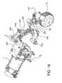
- FIG. 1is a schematic of an anti-tip system A disclosed in the Schaffner '165 patent.
- the drive-train and suspension systemsare mechanically coupled by a longitudinal suspension arm B, pivotally mounted to the main structural frame C about a pivot point D.
- a drive-train assembly EAt one end of the suspension arm B is mounted a drive-train assembly E, and at the other end is mounted an anti-tip wheel F.
- torque created by the drive-train assembly E and applied to the drive wheel Gresults in relative rotational displacement between the drive-train assembly E and the frame C about the pivot D.
- the relative motion therebetweenaffects rotation of the suspension arm B about its pivot D in a clockwise or counterclockwise direction depending upon the direction of the applied torque.
- the anti-tip wheel Fis “actively” lifted or raised to facilitate such operational modes, e.g., curb climbing.
- decelerationcauses a clockwise rotation of the drive-train assembly E, thus creating a downward vertical displacement of the respective anti-tip wheel F.
- the downward motion of the anti-tip wheel Fassists to stabilize the wheelchair when traversing downwardly sloping terrain or a sudden declaration of the wheelchair.
- the anti-tip system“actively” responds to a change in applied torque to vary the position of the anti-tip wheel F.
- the active anti-tip system disclosed in the Schaffner patent '165offers significant advances by comparison to prior art passive systems.
- the one piece construction of the suspension arm B, with its single pivot connection Dnecessarily requires that both the drive-train assembly E and the anti-tip wheel F inscribe the same angle (the angles are identical).
- the arc length or vertical displacement of the anti-tip wheel Fmay be limited by the angle inscribed by the drive-train assembly E, i.e., as a consequence of the fixed proportion.
- an examination of the relationship between the location of the pivot or pivot axis D and the rotational axis of the anti-tip wheel Freveals that when the anti-tip wheel F impacts an obstacle at or near a point which is horizontally in-line with the wheel's rotational axis, the anti-tip wheel F may move downwardly. That is, as a result of the position of the pivot D being relatively above the axis of the anti-tip wheel F, a force couple may tend to rotate the suspension arm B downwardly, contrary to a desired upward motion for climbing curbs and/or other obstacles.
- a linkage arrangementis provided for an active anti-tip system within a powered wheelchair.
- a drive-train assemblyis pivotally mounted to a main structural frame of the wheelchair and a suspension system for biasing the drive-train assembly and the anti-tip wheel to a predetermined resting position.
- the drive-train assemblybi-directionally rotates about the pivot in response to torque applied by or to the assembly.
- the linkage arrangementincludes a suspension arm pivotally mounted to the main structural frame about a pivot at one end thereof and an anti-tip wheel mounted about a rotational axis at the other end.
- the linkagefurther includes at least at least one link operable to transfer the displacement of the drive-train assembly to the suspension arm.
- the rotational axis of the anti-tip wheelis preferably spatially located at a vertical position which is substantially equal to or above the vertical position of the pivot.
- the linkage arrangementis provided with at least one suspension spring to create a biasing force that sets the normal rest position for the linkage and a restoring force for returning the linkage back to its normal position.
- the springmay be disposed forwardly of the pivot of the drive-train assembly and engages the frame at one end and may also be aligned vertically above the link and supports the suspension arm and the drive assembly.
- the linkagemay include a bell crank pivotably secured to the frame.
- the bell crank linkageserves to transfer the motion for the drive-train assembly to the anti-tip wheels and may amplify the motion by adjustment of the size of the legs of the crank.
- FIG. 1is a schematic view of an example of a prior art active anti-tip system for use in powered vehicles.
- FIG. 2is a partial side view of a linkage arrangement within a powered vehicle having one of its drive-wheels removed to more clearly show the present invention.
- FIG. 3is an enlarged partial side view of the linkage arrangement of the embodiment of FIG. 2 .
- FIG. 4is a partial side view of the linkage of FIGS. 2 and 3 reacting in response to motor torque or acceleration of the vehicle.
- FIG. 5is a partial side view of the linkage of FIGS. 2 and 3 reacting in response to braking or deceleration of the vehicle.
- FIG. 6is a partial side view of an alternate embodiment of a linkage arrangement within a powered vehicle having one of its drive wheels removed to more clearly show the present invention.
- FIG. 7is a partial side view of the linkage arrangement of FIG. 6 reacting in response to motor torque or acceleration of the vehicle.
- FIG. 8is a partial side view of the linkage arrangement of FIGS. 6 and 7 reacting in response to braking or deceleration of the vehicle.
- FIG. 9is a partial side view of a further embodiment of a linkage arrangement within a powered vehicle having one of its drive-wheels removed to more clearly show the present invention.
- FIG. 10is a partial side view of the linkage arrangement of FIG. 9 reacting in response to motor torque or acceleration of the vehicle.
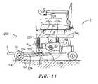
- FIG. 11is a partial side view of the linkage arrangement of FIGS. 9 and 10 reacting in response to braking or deceleration of the vehicle.
- FIG. 12is a perspective view of a further embodiment of a linkage arrangement within a powered vehicle having one of its drive wheels removed to more clearly show the present invention.
- FIG. 13is a enlarged view of the linkage arrangement of the embodiment shown in FIG. 11 .
- FIG. 14is a partial side view of the linkage arrangement of FIGS. 12 and 13 reacting in response to motor torque or acceleration of the vehicle.
- FIG. 15is a partial side view of a further embodiment of a linkage arrangement within a powered vehicle having one of its drive wheels removed to more clearly show the present invention.
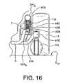
- FIG. 16is a partial front elevation of the linkage arrangement of FIG. 15 with portions of the vehicle frame being removed to more clearly show the features of the present invention.
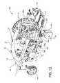
- FIG. 17is a partial perspective view of a still further linkage arrangement within a powered vehicle having the near drive wheel removed and having the opposite side drive train assembly omitted to more clearly show the structure of present invention within the wheelchair assembly.
- FIG. 18is a perspective view of the linkage arrangement of the embodiment shown in FIG. 17 .
- FIG. 19is a partial side view of the linkage arrangement of FIGS. 17 and 18 reacting in response to motor torque or acceleration of the vehicle.
- FIG. 20is a partial side view of the linkage arrangement of FIGS. 17-19 reacting in response to breaking or deceleration of the vehicle.
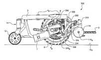
- FIG. 2depicts a power wheelchair 2 including an active anti-tip system linkage 20 according to the present invention.
- the linkage 20may be employed in any vehicle, such as a powered wheelchair, which potentially benefits from stabilization about a pitch axis P A , or enables/controls large angular excursions in relation to a ground plane G P .
- a powered wheelchairwhich potentially benefits from stabilization about a pitch axis P A , or enables/controls large angular excursions in relation to a ground plane G P .
- G Pground plane
- the wheelchair 2comprises an anti-tip system identified generally by the numeral 10 , a main structural frame 3 , a seat 4 for supporting a wheelchair occupant (not shown), a footrest assembly 5 for supporting the feet and legs (also not shown) of the occupant, and a pair a drive wheels 6 (shown schematically) each being independently controlled and driven by a drive-train assembly 7 .
- Each drive-train assembly 7is pivotally mounted to the main structural frame 3 about a pivot 8 to effect relative rotation therebetween in response to positive or negative acceleration or torque.
- a suspension assembly 9is provided for biasing the drive-train assembly 7 and anti-tip system 10 generally to a predetermined operating position.
- the linkage 20 of the present inventionis defined as the elements between the drive-train assembly 7 and the pivot or suspension arm supporting the anti-tip wheel 16 .
- the anti-tip wheel 16is mounted for rotation about axis 16 A which lies substantially at or above the vertical position of the pivot or pivot axis 24 A for the suspension arm 24 on the main structural frame 3 .
- a link 34is operably connected to the drive-train assembly 7 at one end and to the suspension arm 24 at the other end. The link 34 acts to transfer bi-directional displacement of the drive-train assembly 7 to the suspension arm 24 .
- the phrase “substantially at or above”means that the pivot 24 A is located at vertical position (relative to a ground plane G P ) which is substantially equal to or less than a distance the vertical position of the rotational axis 16 A of the anti-tip wheel 16 (relative to the ground plane G P ). Furthermore, these spatial relationships are defined in terms of the “resting” position of the system 10 , when the loads acting on the suspension arm 24 or anti-tip wheel 16 are in equilibrium.
- pivot 24 Ais distally spaced from the rotational axis 16 A of the anti-tip wheel 16 .
- the pivot 24 Ais disposed inboard of the forward portions of the main structural frame 3 and is proximal to the position of the drive wheel axis (also called the pitch axis) P A .
- a bracket 30is rigidly mounted to the drive-train assembly 7 and projects forwardly thereof. As illustrated the bracket 30 is substantially parallel to the suspension arm 24 .
- the link 34is pivotally mounted to the suspension arm 24 at one end thereof at a pivot 38 which is positioned between the pivot 24 A and the rotational axis 16 A of the anti-tip wheel 16 .
- the link 34is substantially orthogonal to the longitudinal axis of the suspension arm 24 , and pivotally mounts to the bracket 30 at pivot 42 .
- the bracket 30 and suspension arm 24include a plurality of longitudinally spaced-apart apertures 46 for facilitating longitudinal or angular adjustments of the link 34 relative to the bracket 30 and/or the suspension arm 24 .
- the drive-train assembly 7 and linkage arrangementare biased to a predetermined operating or “resting” position by the suspension assembly 9 .
- the suspension assembly 9comprises a pair of spring strut assemblies 52 a , 52 b , each being disposed on opposite sides of the drive-train pivot 8 .
- each spring strut assembly 52 a , 52 bis interposed between an upper horizontal frame support 3 H S of the main structural frame 3 and the drive-train assembly 7 .
- the first strut 52 ais pivotally mounted to an L-bracket 56 at a point longitudinally forward of the pivot mount 8 .
- the second strut 52 bis pivotally mounted to an upper mounting plate 58 for the drive-train assembly 7 at a point longitudinally aft of the pivot 8 .
- the drive-train assembly 7rotates in a clockwise direction about pivot 8 , indicated by arrow R 7 .
- the rotational directions describedare in relation to a left side view from the perspective of a wheelchair occupant.
- Rotation of the drive-train assembly 7will cause the bracket 30 to rotate in the same clockwise direction, see arrow R 30 , and the link 34 to move in a counterclockwise direction, see arrow R 34 , about pivot 42 .
- Clockwise rotation of the bracket 30effects a substantially upward vertical motion of the link 34 .
- the link 34rotates the suspension arm 24 in a clockwise direction about pivot 24 A , denoted by arrow R 24 , and lifts or raises the anti-tip wheel 16 .
- the length of the suspension arm 24also contributes to the enhanced curb-climbing ability.
- a short suspension arm(having a characteristic short radius), tend to traverse a substantially arcuate path in contrast to a linear path of a relatively longer suspension arm.
- An arcuate pathproduces components of displacement in both a vertical and forward direction. While the forward component is small relative to the vertical component, it will be appreciated that this component can jam or bind an anti-tip wheel as it lifts vertically. This will more likely occur when the axis of the anti-tip wheel is positioned relatively below the pivot of the suspension arm.
- the anti-tip wheeltraverses a more vertical or substantially linear path.
- the forward componentis substantially eliminated along with the propensity for an anti-tip wheel to jam or bind.
- the pivot 24 A of the suspension arm 24is disposed proximal to the longitudinal center of the main structural frame 3 .
- bracket 30 , link 34 and suspension arm 24rotate in directions opposite to those described above with regard to FIG. 4 to urge the anti-tip wheel 16 into contact with the ground plane G P .
- a downward forceis produced to counteract the forward pitch or tipping motion of the wheelchair 2 upon deceleration.
- the mounting location 38 of the link 34is at a point on the suspension arm 24 that is closer to the anti-tip wheel 16 than to the pivot 24 A .
- This mounting locationfunctions to augment the structural rigidity of the suspension arm 24 to more effectively stabilize the wheelchair 2 . That is, by effecting a stiff structure, structural rigidity of the linkage 20 , rapidly arrests and stabilizes the wheelchair about the pitch axis P A . Moving the link 34 closer to the pivot 24 A will, conversely, serve to accentuate the effect of the motion of the drive-train assembly 7 ; that is, the same linear movement of the pivot 38 , when positioned closer to suspension arm pivot 24 A will result in a greater movement of the anti-tip wheels 16 , at the end of the arm.
- FIGS. 6-8depict and an alternate embodiment 20 of the linkage arrangement adapted for use in powered wheelchairs 2 .
- the linkage arrangement 120employs a suspension arm 124 having a pivot point 124 A which is spatially positioned at or below the rotational axis 116 A of the anti-tip caster wheel 116 .
- Two links 130 , 134are operatively connected to the drive-train assembly 7 and the suspension arm 124 .
- the first link 130is fixed to the drive-train assembly 7 while the second link 134 is pivotally mounted to the suspension arm 124 , with bell-crank 60 operatively positioned therebetween.
- the anti-tip wheel 116 as illustrated in this figureis a caster type wheel and, as shown, is normally in contact with the ground G P .
- a bi-directional spring strut 88biases the anti-tip system to a resting position.
- the strut 88is pivotally mounted to the suspension arm 124 , rather than to the drive-train assembly 7 as in FIGS.
- the linkage arrangement 120includes a bell-crank link 60 for re-directing and/or amplifying input motions originating from the drive-train assembly 7 .
- the bell-crank 60is pivotally mounted about a pivot 78 on the main structural frame 3 .
- the bell-crank 60includes first and second crank arms 60 - 1 , 60 - 2 which, as illustrated, define a right angle therebetween.
- the relative angular orientation of the arms 60 - 1 , 60 - 2may vary depending on the positioning of connecting links and the location of the pivot 78 .
- the first and second crank arms 60 - 1 , 60 - 2also differ in length.
- the first crank arm 60 - 1is longer than the second arm 60 - 2 .
- first to second lengththere is a 2:1 length ratio (i.e., first to second length).
- first crank arm 60 - 1is oriented substantially vertically with respect to the longitudinal axis of the suspension arm 24 and pivotally mounted to the third link 64 .
- the second crank arm 60 - 2is substantially horizontal with respect to the longitudinal axis of the suspension arm 24 and is pivotally mounted to the second link 34 . Again, these parameters and positions may vary as desired.
- the drive-train assembly 7is pivotably connected to the first link 130 by a substantially vertical projection on the drive-train mounting plate 58 .
- the first link 130includes an elliptically-shaped aperture or thru-slot 64 to allow the pivot connection to float.
- FIGS. 7 and 8are analogous to FIGS. 4 and 5 , respectively, wherein the linkage kinematics are illustrated.
- One difference between the linkage arrangement 120 of FIGS. 7 and 8relates to the amplification of displacement gained from the bell-crank 60 .
- the bell crank 60serves to redirect horizontal linear motion of the drive-train 7 to create a vertical motion of the anti-tip wheel 116 .
- the bell-crank 60increases the mechanical advantage for a given applied torque. This enables a relatively close positioning of the pivot connection 84 to the pivot 124 A , while still resulting in a significant motion by the suspension arm 124 .
- the anti-tip caster wheel 116is able to traverse a large vertical distance. That is, the vertical displacement of the anti-tip caster wheel 116 is magnified by the bell crank 60 and the proximal spacing of the pivot connection 84 to the axis 124 A .
- the anti-tip caster wheel 116rides normally on the ground G P .
- the drive-train assembly 7lifts and creates a force, through the linkage 120 , that forces the anti-tip wheel 116 into the ground G P and restricts the ability of the suspension 88 to compress. This arrangement limits pitch of the wheelchair. Further, in the normal rest position, a force on the foot plate 5 (such as by a person standing) will not cause significant rotation of the wheelchair about the pitch axis P A .
- the wheelchair 2includes a further embodiment of an anti-tip system linkage 220 which is supported on a main structural frame 3 .
- a drive-train assembly 7is pivotally mounted to the frame 3 about a pivot 8 to effect relative rotation therebetween in response to positive or negative acceleration or torque.
- a suspension assembly 209is provided for biasing the drive-train assembly 7 and the anti-tip system to a predetermined operating position.
- a suspension arm 224is pivotally mounted to the frame 3 at pivot 224 A .
- At the opposite end of the suspension arm 224is mounted on anti-tip wheel 16 which is rotatable about a rotational axis 16 A .
- the position of the rotational axis 16 Alie substantially at or above the vertical position of the pivot 224 A .
- the pivot 224 Ais disposed inboard of the front of the frame 3 and is positioned proximal to the drive wheel axis, or pitch axis P A , and substantially vertically below the drive-train assembly pivot 8 .
- a mounting extension 230projects from the mounting plate 258 for the drive-train assembly 7 .
- a link 234is pivotally mounted 238 to the suspension arm 224 between the pivot 224 A and the rotational axis 16 A of the anti-tip wheel 16 .
- the link 234is substantially orthogonal to the longitudinal axis of the suspension arm 224 , and mounts to the extension 230 at a pivot 242 .
- the anti-tip wheelhas a fixed axis, rather than being a caster, as is shown in FIGS. 6-8 .
- caster type anti-tip wheelsmay be used on this embodiment, as well as any of embodiments shown.
- the anti-tip wheelmay be positioned as close to the ground as desired. Casters will normally ride on the ground.
- the suspension assembly 209comprises a pair of suspension springs 252 a , 252 b , disposed on opposite sides of the drive-train pivot 8 .
- Each of the suspension springs 252 a , 252 bis interposed between an upper horizontal frame support 3 H S of the main structural frame 3 and the drive-train assembly 7 .
- the forward spring 252 ais mounted adjacent to or directly above the pivot 242 for link 234 .
- the aft suspension spring 252 b(considered to be optional) is mounted to an upper mounting plate 258 for the drive-train assembly 7 at a point longitudinally aft of the mounting pivot 8 . When resting, the spring bias of the assembly 209 acting on the drive-train assembly 7 is in equilibrium.
- the link 234serves to move the suspension arm 224 which rotates to urge the anti-tip wheel 16 upward or into contact with the ground plane G P .
- the kinematics of the linkage arrangementwill not be again described in detail.
- linkage arrangements abovehave been described in terms of various embodiments which exemplify the anticipated use and application of the invention, other embodiments are contemplated and also fall within the scope and spirit of the invention.
- linkage arrangementshave been illustrated and described in terms of a forward anti-tip system, the linkage arrangements are equally applicable to a rearward or aft stabilization of a powered wheelchair.
- the anti-tip wheelmay be either out of ground contact or in contact with the ground, whether employing a long suspension arm (such as that shown in FIGS. 2-5 ), a relatively shorter suspension arm ( FIGS. 6-8 ), or when including a bell crank ( FIGS. 6-8 ). Also, the anti-tip wheel may be in or out of ground contact when disposed in combination with any of the linkage arrangements.
- the linkage arrangements as illustratedmay include apertures for enabling adjustment.
- Other adjustment devicesare also contemplated.
- a longitudinal slotmay be employed in the bracket or link and a sliding pivot mount may be engaged within the slot.
- FIGS. 12-13there is illustrated a further vehicle structure which incorporates the features of the linkage arrangement and anti-tip systems of the present invention.
- the wheelchair vehicle in these figuresis generally referred to by the numeral 302 and includes a main structural frame 3 which supports a seat (not shown) that is mounted on seat post sockets 4 A .
- a footrest 5is positioned on a forward portion of the frame 3 and a drive-train assembly 7 is mounted on the frame 3 at pivot 8 .
- one drive wheelhas been removed for purposes of illustrating the linkage 320 .
- the far side drive wheel 6has been illustrated in this FIG. 12 .
- Attached to the rear of the frame 3is the rear suspension 14 which, in this embodiment, includes a rocker arm 11 pivotally mounted to the frame at pivot 13 and including caster wheels 12 at each projected end of the rocker arm 11 .
- the linkage arrangement 320is specifically illustrated with the remaining portions of the vehicle being removed.
- the linkage 320includes a first link 334 attached at one end at pivot 342 to a bracket 356 extending from drive-train mounting plate 358 .
- the opposite end of the first link 334is connected at pivot 338 to the suspension arm 324 .
- the suspension arm 324is secured to the frame ( FIG. 12 ) at suspension pivot 324 A .
- a caster assembly 116serving as the anti-tip wheel for the suspension.
- the anti-tip wheel 116includes a anti-tip wheel axel 116 A and also includes a flexible mount 318 which permits limited movement of the anti-tip wheel back towards the linkage 320 when it engages an obstacle.
- a stop 359is also provided on the mounting plate 358 to limit upward movement of the drive-train assembly about pivot 8 .
- a suspension assembly 309is provided.
- the suspensionis pivotally mounted to the bracket 356 on the mounting plate 358 .
- the upper end of the suspension 309 Aengages the upper portion of the frame 3 . From this arrangement, it can be seen that rotation of the mounting plate 358 about the pivot 8 will cause a corresponding movement of the suspension arm 324 by means of the link 334 . Movement of the link 334 , which is transferred to the suspension arm 324 , causes a pivoting motion of the suspension arm 324 about its pivot 324 A .
- the pivoting motion of the suspension arm 324causes a corresponding motion to the anti-tip wheel 116 .
- FIG. 14there is shown the operational mode of the vehicle 302 where an increased torque output is provided, such as may be required when accelerating or climbing a curb and/or obstacle.
- the drive-train assembly 7rotates in a counter-clockwise direction (as seen in this FIG. 14 ) about pivot 8 as indicated by arrow R 7 . Rotation of the drive-train assembly 7 will cause the mounting plate 358 to also rotate, lifting the link 334 upwardly. Due to the connection between the link 334 and the suspension arm 324 , the suspension arm also pivots in a counter clockwise direction about the suspension arm pivot 324 A . The counter clockwise rotation (again as seen in FIG. 14 ) of the suspension arm 324 causes the anti-tip wheel 116 to lift off of the ground plane G P .
- the suspension 309compresses due to the upward movement of the bracket 356 and the fixed positioning of the frame 3 . Compression of the spring creates a restoration force for the linkage, returning the suspension arm 324 and anti-tip wheel 116 to its normal position upon removal of the torque of the drive-train 7 .
- a deceleration or braking torquewill cause a corresponding opposite reaction by the assembly about the pivot 8 thereby forcing the anti-tip wheel into the ground plane G P .
- FIGS. 15 and 16a further embodiment of the linkage arrangement as contemplated by the present invention.
- the link connecting the drive-train and the suspension armhas been adapted to accommodate various modifications in the frame and other structures.
- the vehicle 402includes a frame 3 supporting a drive-train assembly 7 about a pivot 8 , with the drive-train assembly 7 driving a drive wheel 6 .
- One drive wheel 6is illustrated in FIG. 15 , with the relatively closer drive wheel removed for clarity.
- the battery structures which are typically centrally mounted within the frame 3have also been removed for clarity.
- the frame 3also supports a seat (not shown). Mounting sockets 4 A are provided for purposes of mounting a seat, although other mounting arrangements may be provided as desired.
- a rear suspension 14is also illustrated.
- Front anti-tip wheels 116project forwardly of the frame 3 and are mounted on a suspension arm 424 by means of resilient mount 418 .
- the suspension arm 424is pivotally mounted to the frame 3 at pivot 424 A .
- a link 434is pivotally connected to the suspension arm 424 at pivot 438 .
- the upper end of the link 434is pivotally connected 442 to a bracket 456 which is formed as part of the drive-train mounting plate 458 .
- the mounting plate 458is pivotally connected to the frame at pivot 8 and supports the drive-train assembly 7 .
- a suspension 409extends between the bracket 456 and the upper portion of the frame 3 of the vehicle 402 .
- the link 434includes a forwardly projecting curvature.
- the pivot 442 between one end of the link 434 and the bracket 456is relatively rearward of the pivot 438 that connects the link 434 to the suspension arm 424 .
- the link 434has an inward step towards the central portion of the vehicle 402 .
- the pivot 442 between the link 434 and the bracket 456is closer to the drive wheel 6 than is the connection between the link 434 and the suspension arm 424 .
- the suspension arm 424includes an outwardly projecting portion such that the caster 116 and its mount 418 extend relatively outward from the frame 3 , as compared to its pivot 424 A . In this FIG.
- the lower portion of the frame 3is partially broken away so as to expose the suspension 409 as it extends between the bracket 456 and the upper frame portion 3 H S .
- a further feature of these linkage connectionsmay include the positioning of the pivot 438 for linkage 434 within the suspension arm 424 .
- a slot or groovemay be formed in the suspension arm and the end of the link 434 inserted therein.
- FIGS. 17-20there is shown a further variation of a vehicle having an anti-tip suspension as contemplated by the present invention.
- the wheelchair 502includes a structural frame 3 which supports a seat (not shown).
- Seat mounting sockets 4 Aare provided on the frame 3
- seat mounting bars 4 Bare provided for attachment of the seat thereto.
- the drive-train assembly 7is pivotally mounted to the frame 3 at pivot 8 .
- An opposing drive train assembly 7(including anti-tip wheel) has been omitted from the illustration for purposes of clarity.
- a drive wheel 6is shown on the far side of the vehicle frame with the near side drive wheel having been removed for illustration purposes.
- the axis of rotation of the drive wheel 6constitutes the pitch axis P A for the vehicle 502 .
- a rear suspension 14is provided with a rocker arm 11 and caster wheels 12 .
- a further suspension assembly 513is provided for fixing the rocker arm 11 to the frame 3 .
- the suspension assembly 513includes dual dampening mechanisms 515 having a spring and a central piston.
- the dampening mechanisms 515are attached at one end to the frame 3 and at the opposite end to a bar 514 .
- the bar 514is pivotally mounted to the frame at pivots 520 by means of arms 519 .
- FIG. 18shows an enlarged view of the linkage arrangement of the present embodiment.
- the drive-train assembly 7is attached to the mounting plate 558 having a bracket 556 which connects to the drive-train pivot 8 .
- the bracket 556further connects to the link 534 at pivot 542 .
- Suspension 509is also connected to the bracket 556 at one end.
- the link 534extends downwardly to a pivot 538 on the suspension arm 524 .
- Suspension 509also attaches to the suspension arm 524 at pivot 560 .
- a series of mounting holesare provided on the suspension arm 524 for the attachment of the suspension 509 at a variety of positions. Mounting holes are also provided for attachment of the link 534 to the pivot arm 524 , permitting re-positioning of the pivot 538 .
- the anti-tip wheel 116 shownis a caster type wheel having a caster support 518 including a resilient mounting to permit limited deflection of the caster upon engagement of an obstacle.
- a torque generated by the drive-train 7 for purposes of climbing a curve or obstaclecauses a rotation of the drive-train 7 about pivot 8 as illustrated by arrow R 7 .
- the drive-train assembly 7moves counter-clockwise about the pivot 8 , causing the link 534 to move upwardly along with the bracket ( 556 ).
- the link 534thus lifts the suspension arm 524 , causing a counter-clockwise rotation about its pivot 524 A .
- the pivoting rotation of the suspension arm 524causes the anti-tip wheel 116 to lift off the ground plane G P and, as illustrated in FIG. 19 , to step up over the obstacle.
- the counter-clockwise rotation of the drive-train 7will cause a slight compression of the suspension 509 due to the differences in the location of attachment of the suspension arm 524 and the position of the link 534 .
- the suspensionwill normally cause the drive-train 7 to move back into its normal rest position, and lower the anti-tip wheel 116 .
- the force of the suspension on the obstacle surface O Pwill help lift the frame 3 and the drive wheel 6 over the obstacle.
- suspension members 515will also compress upon any counter-clockwise rotation of the frame 3 about the pitch axis P A .
- the motion of the frame 3 back on the suspension 515will also cause a pivoting motion of the arms 519 .
- FIG. 20a further reaction of the vehicle in response to deceleration and/or the response of the linkage arrangement to variations in the ground plane.
- the anti-tip wheel 116has moved over a curb and is in contact with a plane that is relatively below the ground plane G P on which the drive wheel sits and the rear casters 12 rest.
- the suspension 509extends to permit the anti-tip wheel 116 to engage the lower surface.
- the linkage 534adapts to this motion.
- the drive-train assembly 7rotates clockwise (in this FIG. 20 ) about the pivot 8 as illustrated by arrow R 7 .
- the connection between the bracket 556 and the link 534causes the suspension arm 524 to move downwardly to help engage the lower plane. If the caster 116 was on level ground with the drive wheel 6 and rear caster 12 , the drive-train 7 will force the front casters 116 into the ground, providing a force that resists the pitch of the vehicle about the pitch axis P a . A similar force would be provided by the suspension 509 in the normal rest position should the occupant stand on the footplate (not shown). Thus, pitch of the vehicle would not occur if a force were applied to the footplate on one side of the pitch axis P a . The spring force and the linkage arrangement between the drive-train 7 and the anti-tip wheel 116 adds further support.
Landscapes
- Health & Medical Sciences (AREA)
- Life Sciences & Earth Sciences (AREA)
- Animal Behavior & Ethology (AREA)
- General Health & Medical Sciences (AREA)
- Public Health (AREA)
- Veterinary Medicine (AREA)
- Handcart (AREA)
- Vehicle Body Suspensions (AREA)
- Automatic Cycles, And Cycles In General (AREA)
Abstract
Description
Claims (16)
Priority Applications (8)
| Application Number | Priority Date | Filing Date | Title |
|---|---|---|---|
| US10/962,014US7389835B2 (en) | 2003-10-08 | 2004-10-08 | Active anti-tip system for power wheelchairs |
| US11/180,207US7413038B2 (en) | 2003-10-08 | 2005-07-13 | Anti-tip system for a power wheelchair |
| US12/170,876US7726689B2 (en) | 2003-10-08 | 2008-07-10 | Anti-tip system for a power wheelchair |
| US12/780,318US7931300B2 (en) | 2003-10-08 | 2010-05-14 | Anti-tip system for a power wheelchair |
| US13/010,006US8181992B2 (en) | 2003-10-08 | 2011-01-20 | Anti-tip system for a power wheelchair |
| US13/464,099US8408598B2 (en) | 2003-10-08 | 2012-05-04 | Anti-tip system for a power wheelchair |
| US13/854,334US9301894B2 (en) | 2003-10-08 | 2013-04-01 | Anti-tip system for a power wheelchair |
| US14/504,259US9526664B2 (en) | 2003-10-08 | 2014-10-01 | Anti-tip system for a power wheelchair |
Applications Claiming Priority (3)
| Application Number | Priority Date | Filing Date | Title |
|---|---|---|---|
| US50964903P | 2003-10-08 | 2003-10-08 | |
| US50949503P | 2003-10-08 | 2003-10-08 | |
| US10/962,014US7389835B2 (en) | 2003-10-08 | 2004-10-08 | Active anti-tip system for power wheelchairs |
Related Child Applications (1)
| Application Number | Title | Priority Date | Filing Date |
|---|---|---|---|
| US11/180,207Continuation-In-PartUS7413038B2 (en) | 2003-10-08 | 2005-07-13 | Anti-tip system for a power wheelchair |
Publications (2)
| Publication Number | Publication Date |
|---|---|
| US20050077715A1 US20050077715A1 (en) | 2005-04-14 |
| US7389835B2true US7389835B2 (en) | 2008-06-24 |
Family
ID=34316847
Family Applications (8)
| Application Number | Title | Priority Date | Filing Date |
|---|---|---|---|
| US10/962,014Expired - LifetimeUS7389835B2 (en) | 2003-10-08 | 2004-10-08 | Active anti-tip system for power wheelchairs |
| US11/180,207Active2025-11-12US7413038B2 (en) | 2003-10-08 | 2005-07-13 | Anti-tip system for a power wheelchair |
| US12/170,876Expired - LifetimeUS7726689B2 (en) | 2003-10-08 | 2008-07-10 | Anti-tip system for a power wheelchair |
| US12/780,318Expired - LifetimeUS7931300B2 (en) | 2003-10-08 | 2010-05-14 | Anti-tip system for a power wheelchair |
| US13/010,006Expired - LifetimeUS8181992B2 (en) | 2003-10-08 | 2011-01-20 | Anti-tip system for a power wheelchair |
| US13/464,099Expired - LifetimeUS8408598B2 (en) | 2003-10-08 | 2012-05-04 | Anti-tip system for a power wheelchair |
| US13/854,334Expired - Fee RelatedUS9301894B2 (en) | 2003-10-08 | 2013-04-01 | Anti-tip system for a power wheelchair |
| US14/504,259Expired - Fee RelatedUS9526664B2 (en) | 2003-10-08 | 2014-10-01 | Anti-tip system for a power wheelchair |
Family Applications After (7)
| Application Number | Title | Priority Date | Filing Date |
|---|---|---|---|
| US11/180,207Active2025-11-12US7413038B2 (en) | 2003-10-08 | 2005-07-13 | Anti-tip system for a power wheelchair |
| US12/170,876Expired - LifetimeUS7726689B2 (en) | 2003-10-08 | 2008-07-10 | Anti-tip system for a power wheelchair |
| US12/780,318Expired - LifetimeUS7931300B2 (en) | 2003-10-08 | 2010-05-14 | Anti-tip system for a power wheelchair |
| US13/010,006Expired - LifetimeUS8181992B2 (en) | 2003-10-08 | 2011-01-20 | Anti-tip system for a power wheelchair |
| US13/464,099Expired - LifetimeUS8408598B2 (en) | 2003-10-08 | 2012-05-04 | Anti-tip system for a power wheelchair |
| US13/854,334Expired - Fee RelatedUS9301894B2 (en) | 2003-10-08 | 2013-04-01 | Anti-tip system for a power wheelchair |
| US14/504,259Expired - Fee RelatedUS9526664B2 (en) | 2003-10-08 | 2014-10-01 | Anti-tip system for a power wheelchair |
Country Status (3)
| Country | Link |
|---|---|
| US (8) | US7389835B2 (en) |
| EP (1) | EP1522295A3 (en) |
| CA (1) | CA2484325C (en) |
Cited By (33)
| Publication number | Priority date | Publication date | Assignee | Title |
|---|---|---|---|---|
| US20070107955A1 (en)* | 2005-07-14 | 2007-05-17 | John Puskar-Pasewicz | Powered wheelchair configurations and related methods of use |
| US20070290492A1 (en)* | 2006-06-19 | 2007-12-20 | Burke, Inc. | Personal mobility vehicle with anti-tip suspension |
| US20080066974A1 (en)* | 2006-09-14 | 2008-03-20 | Pearlman Jonathan L | Personal vehicle |
| US20080087481A1 (en)* | 2006-09-18 | 2008-04-17 | Pride Mobility Products Corporation | Powered wheelchair having an articulating beam and related methods of use |
| US20080169136A1 (en)* | 2004-04-08 | 2008-07-17 | Levo Ag Wohlen | Wheelchair With A Middle Wheel Drive, In Particular Raising Wheelchair |
| US20080264702A1 (en)* | 2007-04-25 | 2008-10-30 | Merits Health Products Co., Ltd. | Power wheelchair |
| US20090145677A1 (en)* | 2006-08-16 | 2009-06-11 | Sunrise Medical Hhg Inc. | Personal mobility vehicle having a pivoting suspension with a torque activated release mechanism |
| US20100004820A1 (en)* | 2007-02-14 | 2010-01-07 | Invacare Corporation | Wheelchair with suspension |
| US20100215055A1 (en)* | 2009-02-25 | 2010-08-26 | Glaser Stephen D | Method and apparatus for using multiple protocols on a communication link |
| US20100213683A1 (en)* | 2009-02-25 | 2010-08-26 | Karma Medical Products Co., Ltd. | Chassis structure for mid-wheel drive power wheelchair |
| US20100301576A1 (en)* | 2007-05-08 | 2010-12-02 | Eric Dugas | Wheelchair base |
| WO2011044405A1 (en)* | 2009-10-09 | 2011-04-14 | Invacare Corporation | Wheelchair suspension |
| US20110215540A1 (en)* | 2007-08-24 | 2011-09-08 | Levo Ag Wohlen | Vehicle with central wheel drive, in particular a wheelchair or stand-up wheelchair |
| US20110253464A1 (en)* | 2010-04-15 | 2011-10-20 | Freerider Corp. | Suspension system for electric wheelchair |
| US20120080244A1 (en)* | 2010-09-30 | 2012-04-05 | Jen-En Hou | Electric-powered scooter with independent ground engaging mechanisms |
| US8172016B2 (en) | 2000-10-27 | 2012-05-08 | Invacare Corporation | Obstacle traversing wheelchair |
| US8172015B2 (en) | 2001-10-10 | 2012-05-08 | Invacare Corporation | Wheelchair suspension |
| US20120138376A1 (en)* | 2005-08-18 | 2012-06-07 | Sunrise Medical Hhg Inc. | Midwheel drive wheelchair with independent front and rear suspension |
| US8272461B2 (en) | 2007-02-08 | 2012-09-25 | Invacare Corporation | Wheelchair suspension |
| US8297388B2 (en) | 2007-01-12 | 2012-10-30 | Invacare International Sarl | Wheelchair with suspension arms |
| US8534679B2 (en) | 2002-10-25 | 2013-09-17 | Invacare Corporation | Suspension for wheeled vehicles |
| US8573341B2 (en) | 2001-10-19 | 2013-11-05 | Invacare Corporation | Wheelchair suspension |
| US8851214B2 (en) | 2010-07-15 | 2014-10-07 | Permobil Ab | Electric mid-wheel drive wheelchair |
| US20160051425A1 (en)* | 2014-08-20 | 2016-02-25 | Energy Control Limited | Front suspension system for an electric wheelchair |
| US9308143B2 (en) | 2012-02-15 | 2016-04-12 | Invacare Corporation | Wheelchair suspension |
| US10130532B2 (en) | 2013-12-16 | 2018-11-20 | Pride Mobility Products Corporation | Elevated height wheelchair |
| US10207561B2 (en)* | 2016-09-20 | 2019-02-19 | Herbert Thomas Baumgartner | System and methods for a vehicle with an articulating suspension exploration platform with shock dampening |
| US11123242B2 (en)* | 2018-11-22 | 2021-09-21 | Invacare International Gmbh | Motorized wheelchair chassis and motorized wheelchair comprising the same |
| US11191685B2 (en) | 2016-02-27 | 2021-12-07 | Pride Mobility Products Corporation | Adjustable height wheelchair |
| US11213441B2 (en) | 2002-10-25 | 2022-01-04 | Invacare Corporation | Suspension for wheeled vehicles |
| US11903887B2 (en) | 2020-02-25 | 2024-02-20 | Invacare Corporation | Wheelchair and suspension systems |
| US11957631B2 (en) | 2022-07-13 | 2024-04-16 | Invacare Corporation | Wheelchair and suspension systems |
| US12409085B2 (en) | 2022-07-07 | 2025-09-09 | Permobil Ab | Powered midwheel drive wheelchair with standing capability |
Families Citing this family (68)
| Publication number | Priority date | Publication date | Assignee | Title |
|---|---|---|---|---|
| JP4422415B2 (en)* | 2003-01-17 | 2010-02-24 | トヨタ自動車株式会社 | Motorcycle |
| EP1493418A1 (en)* | 2003-06-30 | 2005-01-05 | Pride Mobility Products Corporation | Suspension system for a powered wheelchair |
| EP1522295A3 (en) | 2003-10-08 | 2005-04-20 | Pride Mobility Products, Corporation | Active anti-tip system for power wheelchairs |
| US7316282B2 (en)* | 2003-10-08 | 2008-01-08 | Pride Mobility Products Corporation | Anti-tip system for wheelchairs |
| US20050206124A1 (en)* | 2004-03-16 | 2005-09-22 | Ronald Levi | Gear-driven anti-tip system for powered wheelchairs |
| US7264272B2 (en)* | 2004-03-16 | 2007-09-04 | Pride Mobility Products Corporation | Bi-directional anti-tip system for powered wheelchairs |
| US20060076748A1 (en)* | 2004-10-08 | 2006-04-13 | Sunrise Medical Hhg Inc. | Wheelchair with damping mechanism |
| US20060076747A1 (en)* | 2004-10-08 | 2006-04-13 | Sunrise Medical Hhg Inc. | Wheelchair suspension system |
| US20060091663A1 (en)* | 2004-10-21 | 2006-05-04 | Sunrise Medical Hhg Inc. | Wheelchair with telescopic anti-tip wheel |
| US7061197B1 (en)* | 2005-06-22 | 2006-06-13 | Wayne-Dalton Corp. | Pivoting and barrier locking operator system |
| ATE520384T1 (en)* | 2005-06-24 | 2011-09-15 | Degonda Rehab Sa | WHEELCHAIR WITH CENTER WHEEL DRIVE |
| US20070045021A1 (en)* | 2005-08-29 | 2007-03-01 | Greig Mark E | Steering for a maneuverable motorized personally operated vehicle |
| US20070045014A1 (en)* | 2005-08-29 | 2007-03-01 | Greig Mark E | Maneuverable motorized personally operated vehicle |
| US20070063502A1 (en)* | 2005-08-29 | 2007-03-22 | Greig Mark E | Steering ratio mechanism for a maneuverable motorized personally operated vehicle |
| US20070045022A1 (en)* | 2005-08-29 | 2007-03-01 | Greig Mark E | Traction control in a maneuverable motorized personally operated vehicle |
| NL1030428C2 (en)* | 2005-11-15 | 2007-05-16 | A & M Consultancy & Invest B V | Wheelchair. |
| CN2882586Y (en)* | 2006-03-08 | 2007-03-28 | 唐承慧 | A connection mechanism of the front and rear arms of a new type of mid-drive electric wheelchair |
| EP1917946A3 (en)* | 2006-11-06 | 2009-03-18 | Sunrise Medical GmbH & Co. KG | Personal mobility vehicle with two stage tilt ability and method for rearward tilting a seat |
| US20080157513A1 (en)* | 2006-12-29 | 2008-07-03 | Merits Health Products Co., Ltd. | Anti-tip assembly for a power wheelchair |
| US20110047050A1 (en)* | 2007-09-07 | 2011-02-24 | Ryan Steelberg | Apparatus, System And Method For A Brand Affinity Engine Using Positive And Negative Mentions And Indexing |
| US20100131337A1 (en)* | 2007-09-07 | 2010-05-27 | Ryan Steelberg | System and method for localized valuations of media assets |
| US8172017B2 (en)* | 2008-01-21 | 2012-05-08 | Wuhan Runlin Science | Circumferential movement device |
| US20090255739A1 (en)* | 2008-04-14 | 2009-10-15 | P & F Brother Industrial Corporation | Power wheelchair |
| US8844961B2 (en) | 2010-04-27 | 2014-09-30 | Levo Ag Wohlen | Stand-up unit for stand-up wheelchairs and chairs, particularly therapy chairs |
| US7971893B1 (en)* | 2008-09-11 | 2011-07-05 | Bobbie Dunn | Wheelchair |
| US20100107094A1 (en)* | 2008-09-26 | 2010-04-29 | Ryan Steelberg | Advertising request and rules-based content provision engine, system and method |
| US20100121702A1 (en)* | 2008-11-06 | 2010-05-13 | Ryan Steelberg | Search and storage engine having variable indexing for information associations and predictive modeling |
| US8286738B2 (en)* | 2009-07-14 | 2012-10-16 | Merits Health Products Co., Ltd. | Wheel set structure of an electric wheelchair |
| FR2956087B1 (en)* | 2010-02-05 | 2012-12-28 | New Live | OBSTACLE CROSSING DEVICE FOR ELECTRICAL WHEELCHAIR. |
| CA2863971C (en)* | 2011-02-07 | 2018-10-09 | Mobility 2000 (Australia) Limited | Step-climbing attachment for a wheeled chair |
| US9398990B2 (en) | 2011-07-06 | 2016-07-26 | W Mark Richter | Motion-based power assist system for wheelchairs |
| JP5821425B2 (en)* | 2011-08-31 | 2015-11-24 | マツダ株式会社 | Vehicle body structure |
| WO2013041964A1 (en)* | 2011-09-20 | 2013-03-28 | Maurer Balz | Powered wheelchair with articulating drive wheels |
| US9144525B2 (en)* | 2013-03-14 | 2015-09-29 | Max Mobility, Llc. | Motion assistance system for wheelchairs |
| CA2912396A1 (en) | 2013-05-17 | 2014-11-20 | Dane Technologies, Inc. | Devices relating to multifunctional aircraft aisle wheelchair |
| EP2829258B1 (en)* | 2013-07-24 | 2016-09-21 | Next Generation Mobility Pty Ltd | Wheelchair structure and suspension assembly |
| JP6358731B2 (en)* | 2013-08-30 | 2018-07-18 | 国立大学法人広島大学 | Wheel type moving body and wheelchair |
| TWI516688B (en) | 2013-10-22 | 2016-01-11 | 電能有限公司 | Suspension structure for electric wheelchair |
| CN104546331A (en)* | 2013-10-28 | 2015-04-29 | 电能有限公司 | Suspension structure for electric wheelchair |
| US9393166B2 (en) | 2013-12-19 | 2016-07-19 | King Fahd University Of Petroleum And Minerals | Wheelchair suspension system comprising of an encased set of springs with a damper, and method for enhancing stability |
| US8740240B1 (en)* | 2013-12-23 | 2014-06-03 | Maynard I. Merel | User-operated mobility apparatus |
| US20150182871A1 (en)* | 2014-01-02 | 2015-07-02 | Kun Yuan Tong | Flying disc equipped with V-shaped lifting blades |
| US9463122B2 (en) | 2014-01-15 | 2016-10-11 | Thomas A. Pirone | Wheeled lifting device |
| CN106176080A (en)* | 2014-08-27 | 2016-12-07 | 电能有限公司 | the front suspension system of electric wheelchair |
| KR101660156B1 (en) | 2015-01-20 | 2016-09-26 | 에너지 컨트롤 리미티드 | Suspension structure for an electric wheelchair |
| JP5946928B1 (en)* | 2015-01-27 | 2016-07-06 | エネルギー コントロール リミテッドEnergy Control Limited | Suspension structure for electric wheelchair |
| DE102015101552B4 (en) | 2015-02-03 | 2017-06-29 | Energy Control Ltd. | Suspension construction of an electric wheelchair |
| FR3032348B1 (en)* | 2015-02-06 | 2017-12-08 | Energy Control Ltd | SUSPENSION STRUCTURE FOR AN ELECTRIC WHEELCHAIR |
| US9795524B2 (en) | 2015-02-24 | 2017-10-24 | Max Mobility, Llc | Assistive driving system for a wheelchair |
| US10052247B2 (en)* | 2015-08-24 | 2018-08-21 | Dream Roller Mobility, LLC | Wheelchair with four wheel independent suspension and modular seating |
| US10912688B2 (en) | 2015-09-25 | 2021-02-09 | The United States Government As Represented By The Department Of Veterans Affairs | Mobility enhancement wheelchair |
| DE102016118037A1 (en) | 2016-09-23 | 2018-03-29 | Otto Bock Mobility Solutions Gmbh | wheelchair |
| TWI623461B (en)* | 2016-12-14 | 2018-05-11 | 程政群 | Carrier joined with self-balancing vehicle |
| EP3354247B1 (en)* | 2017-01-31 | 2020-03-18 | Permobil AB | Swing arm assembly for a mid-wheel drive wheelchair |
| US10335330B2 (en) | 2017-03-02 | 2019-07-02 | Travelsys4u Ltd. | Motor-driven chair steered by seat rotation |
| US10973715B2 (en)* | 2017-05-23 | 2021-04-13 | William Baer | Powered pedestrian apparatus |
| RU178191U1 (en)* | 2017-09-12 | 2018-03-26 | Федеральное государственное бюджетное образовательное учреждение высшего образования "Санкт-Петербургский государственный архитектурно-строительный университет" | ANTI-TURNING VEHICLE DEVICE |
| JP6962554B2 (en)* | 2017-10-13 | 2021-11-05 | 学校法人大阪産業大学 | Wheelbarrow |
| US10167051B1 (en) | 2017-12-12 | 2019-01-01 | Max Mobility, Llc | Assistive driving system for a wheelchair and method for controlling assistive driving system |
| US11001117B2 (en)* | 2018-03-23 | 2021-05-11 | Amazon Technologies, Inc. | Mobile drive unit having a split chassis |
| WO2019195911A1 (en)* | 2018-04-10 | 2019-10-17 | Velox Manufacturing Inc. | Wheelchair suspension |
| AU2020243458A1 (en)* | 2019-03-18 | 2021-08-26 | Motion Concepts L.P. | Suspension system for power wheelchair stander |
| CN111973353B (en)* | 2019-05-21 | 2022-07-19 | 伍必翔 | An electric wheelchair with its pivoting front cantilever and power frame that is elastically linked with the frame |
| CN110254220A (en)* | 2019-07-02 | 2019-09-20 | 胡德阳 | A kind of pulley lever power car |
| AU2021305625A1 (en)* | 2020-07-08 | 2023-02-02 | Pride Mobility Products Corporation | Anti-tip motorized vehicle |
| CN112124426B (en)* | 2020-09-18 | 2025-04-25 | 昆明理工大学 | An all-terrain intelligent agricultural multifunctional power chassis |
| USD1033279S1 (en) | 2022-08-22 | 2024-07-02 | Three Oceans, LLC | Scooter |
| CN115624437B (en)* | 2022-10-19 | 2025-05-30 | 北京理工华汇智能科技有限公司 | A smart wheelchair safety response method and system |
Citations (58)
| Publication number | Priority date | Publication date | Assignee | Title |
|---|---|---|---|---|
| US3104112A (en) | 1962-07-02 | 1963-09-17 | Jesse W Crail | Stair climbing wheel chair |
| US3520378A (en) | 1966-06-23 | 1970-07-14 | Reginald Arthur Slay | Motor-driven wheeled vehicles |
| US3827718A (en) | 1973-05-30 | 1974-08-06 | P Curry | Wheel chair |
| FR2215054A5 (en) | 1973-01-23 | 1974-08-19 | Folco Zambelli Gian Matteo | |
| US4000912A (en) | 1975-02-21 | 1977-01-04 | Mse Corporation | Shock absorber |
| US4128137A (en) | 1976-02-24 | 1978-12-05 | National Research Development Corporation | Peripatetic vehicles |
| FR2399822A1 (en) | 1977-08-09 | 1979-03-09 | Dupont Lit Sa | Folding wheel chair for handicapped people - consists of frame on two drive wheels, with seat mounted by parallel arms raised and lowered by jack |
| US4245847A (en) | 1979-05-24 | 1981-01-20 | Christopher Knott | Wheelchair |
| GB2051702A (en) | 1979-05-24 | 1981-01-21 | Secr Defence | Wheel chair safety device |
| US4513832A (en) | 1982-05-03 | 1985-04-30 | Permobil Ab | Wheeled chassis |
| WO1987006205A1 (en) | 1986-04-09 | 1987-10-22 | Frost Magnus R | Chassis on wheels |
| GB2192595A (en) | 1986-07-17 | 1988-01-20 | Everest & Jennings Limited | Kerb climbing device for a wheeled vehicle |
| US4840394A (en) | 1988-04-21 | 1989-06-20 | The United States Of America As Represented By The Administrator Of The National Aeronautics And Space Administration | Articulated suspension system |
| WO1990006097A1 (en) | 1988-11-28 | 1990-06-14 | Mercado Medic Ab | A wheelchair with a six-wheel chassis |
| US5435404A (en) | 1992-07-31 | 1995-07-25 | Garin, Iii; Paul V. | Powered mobility chair for individual |
| US5564512A (en) | 1992-12-17 | 1996-10-15 | Richard Van Seenus Nederland B.V. | Wheelchair |
| US5772237A (en) | 1996-05-21 | 1998-06-30 | Teftec Corporation | Suspension system for powered wheelchair |
| US5848658A (en) | 1997-10-06 | 1998-12-15 | Invacare Corporation | Adjustable front wheel stabilizer for power wheelchair |
| US5855387A (en) | 1997-05-01 | 1999-01-05 | Caribbean Billing International, Ltd. | Wheel chair with independent suspension |
| US5964473A (en) | 1994-11-18 | 1999-10-12 | Degonda-Rehab S.A. | Wheelchair for transporting or assisting the displacement of at least one user, particularly for handicapped person |
| WO2000008910A2 (en) | 1998-08-14 | 2000-02-24 | Sunrise Medical Hhg Inc. | Resilient suspension system for a wheelchair |
| US6047979A (en) | 1998-04-03 | 2000-04-11 | Geer Products Ltd. | Wheelchair anti-tipping device |
| US6070898A (en) | 1998-08-14 | 2000-06-06 | Sunrise Medical, Inc. | Suspension system for a wheelchair |
| WO2000054718A1 (en) | 1999-03-17 | 2000-09-21 | Permobil Ab | An anti-tip device for a wheelchair |
| US6129165A (en) | 1996-07-03 | 2000-10-10 | Pride Mobility Products, Corporation | Curb-climbing power wheelchair |
| US6135222A (en) | 1998-09-11 | 2000-10-24 | Nissin Medical Industries Co., Ltd. | Installing structure for an electrically-driven wheelchair |
| US6196343B1 (en) | 1998-10-23 | 2001-03-06 | Rollerchair Pty Ltd. | Mid-wheel drive wheelchair |
| JP2001104391A (en) | 1999-10-08 | 2001-04-17 | Yamaha Motor Co Ltd | Wheelchair |
| US6220382B1 (en) | 1998-11-17 | 2001-04-24 | Burke Mobility Products, Inc. | Powered wheelchair with separating frame |
| US6341657B1 (en) | 1998-11-18 | 2002-01-29 | Electric Mobility Corporation | Suspension for central drive vehicle |
| US6357793B1 (en) | 1999-10-29 | 2002-03-19 | Sunrise Medical Hhg Inc. | Anti-tip wheel |
| US20020093172A1 (en) | 2001-01-18 | 2002-07-18 | Watkins Walter A. | Adjustable height anti-tip wheels for a power wheelchair |
| US6460641B1 (en) | 2000-06-29 | 2002-10-08 | Invacare Corporation | Mid-wheel drive wheelchair with front wheel multiple bias suspension and anti-tip assembly |
| US6543798B2 (en) | 2000-04-04 | 2003-04-08 | Pride Mobility Products Corporation | Anti-tip caster suspension for a wheelchair |
| US20030075365A1 (en) | 2001-10-19 | 2003-04-24 | Fought Gerald E. | Wheelchair suspension having pivotal motor mount |
| US6554086B1 (en) | 2000-10-27 | 2003-04-29 | Invacare Corporation | Obstacle traversing wheelchair |
| US20040004342A1 (en) | 2002-04-30 | 2004-01-08 | Mulhern James P. | Rear wheel drive power wheelchair with ground-contacting anti-tip wheels |
| US20040035627A1 (en) | 2002-06-05 | 2004-02-26 | Richey Joseph B. | Mid-wheel drive scooter |
| US20040046358A1 (en) | 2002-09-09 | 2004-03-11 | White Gerald J. | Stabilizing system for a reclinable wheelchair |
| US6705629B2 (en) | 1999-07-09 | 2004-03-16 | Mediquip Holland B.V. | Wheel chair |
| US20040060748A1 (en) | 2001-10-10 | 2004-04-01 | Molnar James H. | Wheelchair suspension |
| US6752230B1 (en) | 2003-01-13 | 2004-06-22 | Shao Shih Huang | Supplementary wheel support for a motorized wheelchair |
| US20040168839A1 (en) | 2003-02-27 | 2004-09-02 | Wu Daniel P.H. | Wheel bracket mechanism for an electric wheelchair equipped with auxiliary wheels |
| US6796568B2 (en) | 2002-05-01 | 2004-09-28 | Pride Mobility Products Corporation | Suspension system for a wheelchair |
| US20040251649A1 (en) | 2003-06-13 | 2004-12-16 | Wu Daniel P.H. | Suspension structure for front wheel assembly of wheelchair |
| US20040262859A1 (en) | 2003-06-30 | 2004-12-30 | Turturiello George A. | Suspension system for a powered wheelchair |
| US20050000742A1 (en) | 2003-07-02 | 2005-01-06 | Mulhern James P. | Rear wheel drive power wheelchair |
| US6851711B2 (en) | 2002-08-16 | 2005-02-08 | Invacare Corporation | Vehicle having an anti-dive/lockout mechanism |
| US20050077714A1 (en)* | 2003-10-08 | 2005-04-14 | Mulhern James P. | Anti-tip system for wheelchairs |
| US20050127631A1 (en) | 2003-12-15 | 2005-06-16 | Schaffner Walter E. | Curb-climbing power wheelchair |
| US6923278B2 (en) | 2002-05-06 | 2005-08-02 | Pride Mobility Products Corporation | Adjustable anti-tip wheels for power wheelchair |
| US20050206149A1 (en) | 2004-03-16 | 2005-09-22 | Mulhern James P | Bi-directional anti-tip system for powered wheelchairs |
| US20060022445A1 (en) | 2003-10-08 | 2006-02-02 | Mulhern James P | Anti-tip system for a power wheelchair |
| US7021641B2 (en) | 2003-08-13 | 2006-04-04 | Pi Hsiang Machinery Mfg. Co. | Suspension structure for wheelchair |
| US20060076747A1 (en) | 2004-10-08 | 2006-04-13 | Sunrise Medical Hhg Inc. | Wheelchair suspension system |
| US20060082117A1 (en) | 2004-10-20 | 2006-04-20 | Turturiello George A | Power wheelchair |
| US20060086554A1 (en) | 2004-10-21 | 2006-04-27 | Sunrise Medical Hhg, Inc. | Wheelchair reversible between front wheel drive and rear wheel drive |
| US7104346B2 (en) | 2003-03-25 | 2006-09-12 | Schaffner Walter E | Power wheelchair |
Family Cites Families (16)
| Publication number | Priority date | Publication date | Assignee | Title |
|---|---|---|---|---|
| US3544525A (en)* | 1968-03-26 | 1970-12-01 | Allied Chem | Process for crystallization,drying and solid-state polymerization of polyesters |
| DE3336032C2 (en)* | 1983-10-04 | 1985-12-12 | AUTOMATIK Apparate-Maschinenbau GmbH, 8754 Großostheim | Device for cooling, drying and granulating strands made of thermoplastics |
| US5234963A (en)* | 1992-05-13 | 1993-08-10 | Gaia Research | Production of encapsulated chemical foaming concentrates |
| US5290913A (en)* | 1992-10-08 | 1994-03-01 | Carrier Vibrating Equipment, Inc. | Method and apparatus for the heat treatment of material |
| JPH06297452A (en)* | 1993-04-15 | 1994-10-25 | Yoshida Kogyo Kk <Ykk> | Synthetic resin granulator |
| US5633018A (en)* | 1995-01-20 | 1997-05-27 | E. I. Du Pont De Nemours And Company | Apparatus for forming crystalline polymer pellets |
| JPH08283394A (en)* | 1995-04-10 | 1996-10-29 | Mitsui Petrochem Ind Ltd | Method for producing polyethylene terephthalate |
| US5944131A (en) | 1996-07-03 | 1999-08-31 | Pride Health Care, Inc. | Mid-wheel drive power wheelchair |
| US5895617A (en)* | 1996-07-31 | 1999-04-20 | The Japan Steel Works, Ltd. | Method and apparatus for transporting underwater cut pellets |
| CA2254372A1 (en) | 1998-11-17 | 2000-05-17 | Everest & Jennings Canadian Limited | Motorized wheelchair |
| AT410942B (en)* | 2001-10-29 | 2003-08-25 | Fellinger Markus | METHOD AND DEVICE FOR INCREASING THE LIMIT VISCOSITY OF POLYESTER |
| KR100567559B1 (en) | 2002-07-25 | 2006-04-05 | 마츠시다 덴코 가부시키가이샤 | Device with photoelectric element |
| US7083195B2 (en)* | 2002-10-25 | 2006-08-01 | Invacare Corporation | Suspension with releasable locking system |
| CA2520914C (en)* | 2003-02-04 | 2010-04-27 | Waco Construction Inc. | Kiln with process water evaporation system |
| US20060076748A1 (en)* | 2004-10-08 | 2006-04-13 | Sunrise Medical Hhg Inc. | Wheelchair with damping mechanism |
| US8037953B2 (en) | 2005-10-17 | 2011-10-18 | Pride Mobility Products Corporation | Powered wheelchair having a side-access battery compartment |
- 2004
- 2004-10-08EPEP04256262Apatent/EP1522295A3/ennot_activeWithdrawn
- 2004-10-08USUS10/962,014patent/US7389835B2/ennot_activeExpired - Lifetime
- 2004-10-08CACA2484325Apatent/CA2484325C/ennot_activeExpired - Lifetime
- 2005
- 2005-07-13USUS11/180,207patent/US7413038B2/enactiveActive
- 2008
- 2008-07-10USUS12/170,876patent/US7726689B2/ennot_activeExpired - Lifetime
- 2010
- 2010-05-14USUS12/780,318patent/US7931300B2/ennot_activeExpired - Lifetime
- 2011
- 2011-01-20USUS13/010,006patent/US8181992B2/ennot_activeExpired - Lifetime
- 2012
- 2012-05-04USUS13/464,099patent/US8408598B2/ennot_activeExpired - Lifetime
- 2013
- 2013-04-01USUS13/854,334patent/US9301894B2/ennot_activeExpired - Fee Related
- 2014
- 2014-10-01USUS14/504,259patent/US9526664B2/ennot_activeExpired - Fee Related
Patent Citations (61)
| Publication number | Priority date | Publication date | Assignee | Title |
|---|---|---|---|---|
| US3104112A (en) | 1962-07-02 | 1963-09-17 | Jesse W Crail | Stair climbing wheel chair |
| US3520378A (en) | 1966-06-23 | 1970-07-14 | Reginald Arthur Slay | Motor-driven wheeled vehicles |
| FR2215054A5 (en) | 1973-01-23 | 1974-08-19 | Folco Zambelli Gian Matteo | |
| US3827718A (en) | 1973-05-30 | 1974-08-06 | P Curry | Wheel chair |
| US4000912A (en) | 1975-02-21 | 1977-01-04 | Mse Corporation | Shock absorber |
| US4128137A (en) | 1976-02-24 | 1978-12-05 | National Research Development Corporation | Peripatetic vehicles |
| FR2399822A1 (en) | 1977-08-09 | 1979-03-09 | Dupont Lit Sa | Folding wheel chair for handicapped people - consists of frame on two drive wheels, with seat mounted by parallel arms raised and lowered by jack |
| US4245847A (en) | 1979-05-24 | 1981-01-20 | Christopher Knott | Wheelchair |
| GB2051702A (en) | 1979-05-24 | 1981-01-21 | Secr Defence | Wheel chair safety device |
| US4513832A (en) | 1982-05-03 | 1985-04-30 | Permobil Ab | Wheeled chassis |
| WO1987006205A1 (en) | 1986-04-09 | 1987-10-22 | Frost Magnus R | Chassis on wheels |
| GB2192595A (en) | 1986-07-17 | 1988-01-20 | Everest & Jennings Limited | Kerb climbing device for a wheeled vehicle |
| US4840394A (en) | 1988-04-21 | 1989-06-20 | The United States Of America As Represented By The Administrator Of The National Aeronautics And Space Administration | Articulated suspension system |
| WO1990006097A1 (en) | 1988-11-28 | 1990-06-14 | Mercado Medic Ab | A wheelchair with a six-wheel chassis |
| US5435404A (en) | 1992-07-31 | 1995-07-25 | Garin, Iii; Paul V. | Powered mobility chair for individual |
| US5564512A (en) | 1992-12-17 | 1996-10-15 | Richard Van Seenus Nederland B.V. | Wheelchair |
| US5964473A (en) | 1994-11-18 | 1999-10-12 | Degonda-Rehab S.A. | Wheelchair for transporting or assisting the displacement of at least one user, particularly for handicapped person |
| US5772237A (en) | 1996-05-21 | 1998-06-30 | Teftec Corporation | Suspension system for powered wheelchair |
| US6129165A (en) | 1996-07-03 | 2000-10-10 | Pride Mobility Products, Corporation | Curb-climbing power wheelchair |
| US5855387A (en) | 1997-05-01 | 1999-01-05 | Caribbean Billing International, Ltd. | Wheel chair with independent suspension |
| US5848658A (en) | 1997-10-06 | 1998-12-15 | Invacare Corporation | Adjustable front wheel stabilizer for power wheelchair |
| US6047979A (en) | 1998-04-03 | 2000-04-11 | Geer Products Ltd. | Wheelchair anti-tipping device |
| WO2000008910A2 (en) | 1998-08-14 | 2000-02-24 | Sunrise Medical Hhg Inc. | Resilient suspension system for a wheelchair |
| US6070898A (en) | 1998-08-14 | 2000-06-06 | Sunrise Medical, Inc. | Suspension system for a wheelchair |
| US6234507B1 (en) | 1998-08-14 | 2001-05-22 | Sunrise Medical Hhg Inc. | Suspension system for a wheelchair |
| US6135222A (en) | 1998-09-11 | 2000-10-24 | Nissin Medical Industries Co., Ltd. | Installing structure for an electrically-driven wheelchair |
| US6196343B1 (en) | 1998-10-23 | 2001-03-06 | Rollerchair Pty Ltd. | Mid-wheel drive wheelchair |
| US6220382B1 (en) | 1998-11-17 | 2001-04-24 | Burke Mobility Products, Inc. | Powered wheelchair with separating frame |
| US6341657B1 (en) | 1998-11-18 | 2002-01-29 | Electric Mobility Corporation | Suspension for central drive vehicle |
| WO2000054718A1 (en) | 1999-03-17 | 2000-09-21 | Permobil Ab | An anti-tip device for a wheelchair |
| US6705629B2 (en) | 1999-07-09 | 2004-03-16 | Mediquip Holland B.V. | Wheel chair |
| JP2001104391A (en) | 1999-10-08 | 2001-04-17 | Yamaha Motor Co Ltd | Wheelchair |
| US6357793B1 (en) | 1999-10-29 | 2002-03-19 | Sunrise Medical Hhg Inc. | Anti-tip wheel |
| US6543798B2 (en) | 2000-04-04 | 2003-04-08 | Pride Mobility Products Corporation | Anti-tip caster suspension for a wheelchair |
| US6460641B1 (en) | 2000-06-29 | 2002-10-08 | Invacare Corporation | Mid-wheel drive wheelchair with front wheel multiple bias suspension and anti-tip assembly |
| US6554086B1 (en) | 2000-10-27 | 2003-04-29 | Invacare Corporation | Obstacle traversing wheelchair |
| US20020093172A1 (en) | 2001-01-18 | 2002-07-18 | Watkins Walter A. | Adjustable height anti-tip wheels for a power wheelchair |
| US6533306B2 (en) | 2001-01-18 | 2003-03-18 | Pride Mobility Products Corporation | Adjustable height anti-tip wheels for a power wheelchair |
| US7040429B2 (en)* | 2001-10-10 | 2006-05-09 | Invacare Corporation | Wheelchair suspension |
| US20040060748A1 (en) | 2001-10-10 | 2004-04-01 | Molnar James H. | Wheelchair suspension |
| US20030075365A1 (en) | 2001-10-19 | 2003-04-24 | Fought Gerald E. | Wheelchair suspension having pivotal motor mount |
| US20040004342A1 (en) | 2002-04-30 | 2004-01-08 | Mulhern James P. | Rear wheel drive power wheelchair with ground-contacting anti-tip wheels |
| US6796568B2 (en) | 2002-05-01 | 2004-09-28 | Pride Mobility Products Corporation | Suspension system for a wheelchair |
| US6923278B2 (en) | 2002-05-06 | 2005-08-02 | Pride Mobility Products Corporation | Adjustable anti-tip wheels for power wheelchair |
| US20040035627A1 (en) | 2002-06-05 | 2004-02-26 | Richey Joseph B. | Mid-wheel drive scooter |
| US6851711B2 (en) | 2002-08-16 | 2005-02-08 | Invacare Corporation | Vehicle having an anti-dive/lockout mechanism |
| US20040046358A1 (en) | 2002-09-09 | 2004-03-11 | White Gerald J. | Stabilizing system for a reclinable wheelchair |
| US6752230B1 (en) | 2003-01-13 | 2004-06-22 | Shao Shih Huang | Supplementary wheel support for a motorized wheelchair |
| US20040168839A1 (en) | 2003-02-27 | 2004-09-02 | Wu Daniel P.H. | Wheel bracket mechanism for an electric wheelchair equipped with auxiliary wheels |
| US7104346B2 (en) | 2003-03-25 | 2006-09-12 | Schaffner Walter E | Power wheelchair |
| US20040251649A1 (en) | 2003-06-13 | 2004-12-16 | Wu Daniel P.H. | Suspension structure for front wheel assembly of wheelchair |
| US20040262859A1 (en) | 2003-06-30 | 2004-12-30 | Turturiello George A. | Suspension system for a powered wheelchair |
| US20050000742A1 (en) | 2003-07-02 | 2005-01-06 | Mulhern James P. | Rear wheel drive power wheelchair |
| US7021641B2 (en) | 2003-08-13 | 2006-04-04 | Pi Hsiang Machinery Mfg. Co. | Suspension structure for wheelchair |
| US20060022445A1 (en) | 2003-10-08 | 2006-02-02 | Mulhern James P | Anti-tip system for a power wheelchair |
| US20050077714A1 (en)* | 2003-10-08 | 2005-04-14 | Mulhern James P. | Anti-tip system for wheelchairs |
| US20050127631A1 (en) | 2003-12-15 | 2005-06-16 | Schaffner Walter E. | Curb-climbing power wheelchair |
| US20050206149A1 (en) | 2004-03-16 | 2005-09-22 | Mulhern James P | Bi-directional anti-tip system for powered wheelchairs |
| US20060076747A1 (en) | 2004-10-08 | 2006-04-13 | Sunrise Medical Hhg Inc. | Wheelchair suspension system |
| US20060082117A1 (en) | 2004-10-20 | 2006-04-20 | Turturiello George A | Power wheelchair |
| US20060086554A1 (en) | 2004-10-21 | 2006-04-27 | Sunrise Medical Hhg, Inc. | Wheelchair reversible between front wheel drive and rear wheel drive |
Non-Patent Citations (1)
| Title |
|---|
| Photographs-Sunrise Medical G-424 (sold from Oct. 1999). |
Cited By (85)
| Publication number | Priority date | Publication date | Assignee | Title |
|---|---|---|---|---|
| US9987177B2 (en) | 2000-10-27 | 2018-06-05 | Invacare Corporation | Obstacle traversing wheelchair |
| US8172016B2 (en) | 2000-10-27 | 2012-05-08 | Invacare Corporation | Obstacle traversing wheelchair |
| US9149398B2 (en) | 2000-10-27 | 2015-10-06 | Invacare Corporation | Obstacle traversing wheelchair |
| US8172015B2 (en) | 2001-10-10 | 2012-05-08 | Invacare Corporation | Wheelchair suspension |
| US9370455B2 (en) | 2001-10-10 | 2016-06-21 | Invacare Corporation | Wheelchair suspension |
| US8573341B2 (en) | 2001-10-19 | 2013-11-05 | Invacare Corporation | Wheelchair suspension |
| US8534679B2 (en) | 2002-10-25 | 2013-09-17 | Invacare Corporation | Suspension for wheeled vehicles |
| US10512572B2 (en) | 2002-10-25 | 2019-12-24 | Invacare Corporation | Suspension for wheeled vehicles |
| US11213441B2 (en) | 2002-10-25 | 2022-01-04 | Invacare Corporation | Suspension for wheeled vehicles |
| US9925100B2 (en) | 2002-10-25 | 2018-03-27 | Invacare Corporation | Suspension for wheeled vehicles |
| US20080169136A1 (en)* | 2004-04-08 | 2008-07-17 | Levo Ag Wohlen | Wheelchair With A Middle Wheel Drive, In Particular Raising Wheelchair |
| US9872804B2 (en) | 2005-07-14 | 2018-01-23 | Pride Mobility Products Corporation | Powered wheelchair configurations and related methods of use |
| US7766106B2 (en) | 2005-07-14 | 2010-08-03 | Pride Mobility Products Corporation | Powered wheelchair configurations and related methods of use |
| US8292010B2 (en) | 2005-07-14 | 2012-10-23 | Pride Mobility Products Corporation | Powered wheelchair configurations and related methods of use |
| US20100258363A1 (en)* | 2005-07-14 | 2010-10-14 | Pride Mobility Products Corporation | Powered wheelchair configurations and related methods of use |
| US9333130B2 (en) | 2005-07-14 | 2016-05-10 | Pride Mobility Products Corporation | Powered wheelchair configurations and related methods of use |
| US8408343B2 (en) | 2005-07-14 | 2013-04-02 | Pride Mobility Products Corporation | Powered wheelchair configurations and related methods of use |
| US20070107955A1 (en)* | 2005-07-14 | 2007-05-17 | John Puskar-Pasewicz | Powered wheelchair configurations and related methods of use |
| US8210556B2 (en)* | 2005-08-18 | 2012-07-03 | Sunrise Medical Hhg, Inc. | Midwheel drive wheelchair with independent front and rear suspension |
| US20120138376A1 (en)* | 2005-08-18 | 2012-06-07 | Sunrise Medical Hhg Inc. | Midwheel drive wheelchair with independent front and rear suspension |
| US7942445B2 (en)* | 2006-06-19 | 2011-05-17 | Burke, Inc. | Personal mobility vehicle with anti-tip suspension |
| US7562903B2 (en)* | 2006-06-19 | 2009-07-21 | Burke, Inc. | Personal mobility vehicle with anti-tip suspension |
| US20070290492A1 (en)* | 2006-06-19 | 2007-12-20 | Burke, Inc. | Personal mobility vehicle with anti-tip suspension |
| US20090302589A1 (en)* | 2006-06-19 | 2009-12-10 | Burke, Inc. | Personal mobility vehicle with anti-tip suspension |
| US20090145677A1 (en)* | 2006-08-16 | 2009-06-11 | Sunrise Medical Hhg Inc. | Personal mobility vehicle having a pivoting suspension with a torque activated release mechanism |
| US8113531B2 (en)* | 2006-08-16 | 2012-02-14 | Sunrise Medical Hhg, Inc. | Personal mobility vehicle having a pivoting suspension with a torque activated release mechanism |
| US7882909B2 (en)* | 2006-09-14 | 2011-02-08 | University Of Pittsburgh | Personal vehicle |
| US20080066974A1 (en)* | 2006-09-14 | 2008-03-20 | Pearlman Jonathan L | Personal vehicle |
| US20080087481A1 (en)* | 2006-09-18 | 2008-04-17 | Pride Mobility Products Corporation | Powered wheelchair having an articulating beam and related methods of use |
| US7735591B2 (en) | 2006-09-18 | 2010-06-15 | Pride Mobility Products Corporation | Powered wheelchair having an articulating beam and related methods of use |
| US8297388B2 (en) | 2007-01-12 | 2012-10-30 | Invacare International Sarl | Wheelchair with suspension arms |
| US9603762B2 (en) | 2007-02-08 | 2017-03-28 | Invacare Corporation | Wheelchair suspension |
| US10265229B2 (en) | 2007-02-08 | 2019-04-23 | Invacare Corporation | Wheelchair suspension |
| US11819464B2 (en) | 2007-02-08 | 2023-11-21 | Invacare Corporation | Wheelchair suspension |
| US10912690B2 (en) | 2007-02-08 | 2021-02-09 | Invacare Corporation | Wheelchair suspension |
| US8272461B2 (en) | 2007-02-08 | 2012-09-25 | Invacare Corporation | Wheelchair suspension |
| US11464687B2 (en) | 2007-02-08 | 2022-10-11 | Invacare Coporation | Wheelchair suspension |
| US8794359B2 (en) | 2007-02-08 | 2014-08-05 | Invacare Corporation | Wheelchair suspension |
| US20100004820A1 (en)* | 2007-02-14 | 2010-01-07 | Invacare Corporation | Wheelchair with suspension |
| US10532626B2 (en) | 2007-02-14 | 2020-01-14 | Invacare Corporation | Stability control system |
| US11097589B2 (en) | 2007-02-14 | 2021-08-24 | Invacare Corporation | Stability control system |
| US11535078B2 (en) | 2007-02-14 | 2022-12-27 | Invacare Corporation | Stability control system |
| US9827823B2 (en) | 2007-02-14 | 2017-11-28 | Invacare Corporation | Stability control system |
| US8910975B2 (en)* | 2007-02-14 | 2014-12-16 | Invacare Corporation | Wheelchair with suspension |
| US9346335B2 (en) | 2007-02-14 | 2016-05-24 | Invacare Corporation | Stability control system |
| US11850906B2 (en) | 2007-02-14 | 2023-12-26 | Invacare Corporation | Stability control system |
| US20080264702A1 (en)* | 2007-04-25 | 2008-10-30 | Merits Health Products Co., Ltd. | Power wheelchair |
| US7775307B2 (en)* | 2007-04-25 | 2010-08-17 | Merite Health Products Co., Ltd. | Power wheelchair |
| US20100301576A1 (en)* | 2007-05-08 | 2010-12-02 | Eric Dugas | Wheelchair base |
| US8177257B2 (en)* | 2007-05-08 | 2012-05-15 | Eric Dugas | Wheelchair base |
| US8118321B2 (en)* | 2007-08-24 | 2012-02-21 | Levo Wohlen | Vehicle with central wheel drive, in particular a wheelchair or stand-up wheelchair |
| US20110215540A1 (en)* | 2007-08-24 | 2011-09-08 | Levo Ag Wohlen | Vehicle with central wheel drive, in particular a wheelchair or stand-up wheelchair |
| US7828310B2 (en)* | 2009-02-25 | 2010-11-09 | Karma Medical Products Co., Ltd. | Chassis structure for mid-wheel drive power wheelchair |
| US20100213683A1 (en)* | 2009-02-25 | 2010-08-26 | Karma Medical Products Co., Ltd. | Chassis structure for mid-wheel drive power wheelchair |
| US20100215055A1 (en)* | 2009-02-25 | 2010-08-26 | Glaser Stephen D | Method and apparatus for using multiple protocols on a communication link |
| US9913768B2 (en) | 2009-10-09 | 2018-03-13 | Invacare Corporation | Wheelchair suspension |
| WO2011044405A1 (en)* | 2009-10-09 | 2011-04-14 | Invacare Corporation | Wheelchair suspension |
| US11857470B2 (en) | 2009-10-09 | 2024-01-02 | Invacare Corporation | Wheelchair suspension |
| US9010470B2 (en) | 2009-10-09 | 2015-04-21 | Invacare Corporation | Wheelchair suspension |
| US11096845B2 (en) | 2009-10-09 | 2021-08-24 | Invacare Corporation | Wheelchair suspension |
| US20110253464A1 (en)* | 2010-04-15 | 2011-10-20 | Freerider Corp. | Suspension system for electric wheelchair |
| US9320661B2 (en) | 2010-07-15 | 2016-04-26 | Permobil Ab | Electric mid-wheel drive wheelchair |
| US8851214B2 (en) | 2010-07-15 | 2014-10-07 | Permobil Ab | Electric mid-wheel drive wheelchair |
| US20120080244A1 (en)* | 2010-09-30 | 2012-04-05 | Jen-En Hou | Electric-powered scooter with independent ground engaging mechanisms |
| US9308143B2 (en) | 2012-02-15 | 2016-04-12 | Invacare Corporation | Wheelchair suspension |
| US9700470B2 (en) | 2012-02-15 | 2017-07-11 | Invacare Corporation | Wheelchair suspension |
| US10434019B2 (en) | 2012-02-15 | 2019-10-08 | Invacare Corporation | Wheelchair suspension |
| US11234875B2 (en) | 2012-02-15 | 2022-02-01 | Invacare Corporation | Wheelchair suspension |
| US10828212B2 (en) | 2013-12-16 | 2020-11-10 | Pride Mobility Products Corporation | Elevated height wheelchair |
| US10588797B2 (en) | 2013-12-16 | 2020-03-17 | Pride Mobility Products Corporation | Elevated height wheelchair |
| US10561548B1 (en) | 2013-12-16 | 2020-02-18 | Pride Mobility Products Corporation | Elevated height wheelchair |
| US11998495B2 (en) | 2013-12-16 | 2024-06-04 | P{ride Mobility Products Corporation | Elevated height wheelchair |
| US11141330B2 (en) | 2013-12-16 | 2021-10-12 | Pride Mobility Products Corporation | Elevated height wheelchair |
| US10687997B2 (en) | 2013-12-16 | 2020-06-23 | Pride Mobility Products Corporation | Elevated height wheelchair |
| US11571345B2 (en) | 2013-12-16 | 2023-02-07 | Pride Mobility Products Corporation | Elevated height wheelchair |
| US10130532B2 (en) | 2013-12-16 | 2018-11-20 | Pride Mobility Products Corporation | Elevated height wheelchair |
| US20160051425A1 (en)* | 2014-08-20 | 2016-02-25 | Energy Control Limited | Front suspension system for an electric wheelchair |
| TWI580415B (en)* | 2014-08-20 | 2017-05-01 | 電能有限公司 | Front suspension system for an electric wheelchair |
| US9358165B2 (en)* | 2014-08-20 | 2016-06-07 | Energy Control Limited | Front suspension system for an electric wheelchair |
| US11191685B2 (en) | 2016-02-27 | 2021-12-07 | Pride Mobility Products Corporation | Adjustable height wheelchair |
| US10207561B2 (en)* | 2016-09-20 | 2019-02-19 | Herbert Thomas Baumgartner | System and methods for a vehicle with an articulating suspension exploration platform with shock dampening |
| US11123242B2 (en)* | 2018-11-22 | 2021-09-21 | Invacare International Gmbh | Motorized wheelchair chassis and motorized wheelchair comprising the same |
| US11903887B2 (en) | 2020-02-25 | 2024-02-20 | Invacare Corporation | Wheelchair and suspension systems |
| US12409085B2 (en) | 2022-07-07 | 2025-09-09 | Permobil Ab | Powered midwheel drive wheelchair with standing capability |
| US11957631B2 (en) | 2022-07-13 | 2024-04-16 | Invacare Corporation | Wheelchair and suspension systems |
Also Published As
| Publication number | Publication date |
|---|---|
| US20060022445A1 (en) | 2006-02-02 |
| US20100219623A1 (en) | 2010-09-02 |
| US20110108348A1 (en) | 2011-05-12 |
| US20080265541A1 (en) | 2008-10-30 |
| US7726689B2 (en) | 2010-06-01 |
| EP1522295A2 (en) | 2005-04-13 |
| EP1522295A3 (en) | 2005-04-20 |
| CA2484325A1 (en) | 2005-04-08 |
| US8408598B2 (en) | 2013-04-02 |
| US20130220717A1 (en) | 2013-08-29 |
| CA2484325C (en) | 2013-09-10 |
| US20120217081A1 (en) | 2012-08-30 |
| US8181992B2 (en) | 2012-05-22 |
| US9301894B2 (en) | 2016-04-05 |
| US9526664B2 (en) | 2016-12-27 |
| US7931300B2 (en) | 2011-04-26 |
| US7413038B2 (en) | 2008-08-19 |
| US20050077715A1 (en) | 2005-04-14 |
| US20150173985A1 (en) | 2015-06-25 |
Similar Documents
| Publication | Publication Date | Title |
|---|---|---|
| US7389835B2 (en) | Active anti-tip system for power wheelchairs | |
| US20210267824A1 (en) | Wheelchair suspension | |
| US7316282B2 (en) | Anti-tip system for wheelchairs | |
| US7219755B2 (en) | Obstacle traversing wheelchair | |
| US8210556B2 (en) | Midwheel drive wheelchair with independent front and rear suspension | |
| US7066290B2 (en) | Wheelchair suspension having pivotal motor mount | |
| US7234554B2 (en) | Rear wheel drive power wheelchair | |
| US7506709B2 (en) | Personal mobility vehicle suspension system having a compensation mechanism | |
| CA2254372A1 (en) | Motorized wheelchair | |
| US20050206124A1 (en) | Gear-driven anti-tip system for powered wheelchairs |
Legal Events
| Date | Code | Title | Description |
|---|---|---|---|
| AS | Assignment | Owner name:PRIDE MOBILITY PRODUCTS CORPORATION, PENNSYLVANIA Free format text:ASSIGNMENT OF ASSIGNORS INTEREST;ASSIGNORS:MULHERN, JAMES P.;LEVI, RONALD;GRYMKO, CHRISTOPHER E.;REEL/FRAME:016298/0994 Effective date:20041007 | |
| STCF | Information on status: patent grant | Free format text:PATENTED CASE | |
| FEPP | Fee payment procedure | Free format text:PAYOR NUMBER ASSIGNED (ORIGINAL EVENT CODE: ASPN); ENTITY STATUS OF PATENT OWNER: LARGE ENTITY | |
| AS | Assignment | Owner name:MANUFACTURERS AND TRADERS TRUST COMPANY, NEW YORK Free format text:SECURITY AGREEMENT;ASSIGNOR:PRIDE MOBILITY PRODUCTS CORPORATION;REEL/FRAME:022408/0671 Effective date:20081107 Owner name:MANUFACTURERS AND TRADERS TRUST COMPANY,NEW YORK Free format text:SECURITY AGREEMENT;ASSIGNOR:PRIDE MOBILITY PRODUCTS CORPORATION;REEL/FRAME:022408/0671 Effective date:20081107 | |
| FPAY | Fee payment | Year of fee payment:4 | |
| FPAY | Fee payment | Year of fee payment:8 | |
| MAFP | Maintenance fee payment | Free format text:PAYMENT OF MAINTENANCE FEE, 12TH YEAR, LARGE ENTITY (ORIGINAL EVENT CODE: M1553); ENTITY STATUS OF PATENT OWNER: LARGE ENTITY Year of fee payment:12 | |
| AS | Assignment | Owner name:M&T BANK, NEW YORK Free format text:SECURITY INTEREST;ASSIGNOR:PRIDE MOBILITY PRODUCTS CORPORATION;REEL/FRAME:051763/0897 Effective date:20200128 |