US7388579B2 - Reduced power consumption for a graphics accelerator and display - Google Patents
Reduced power consumption for a graphics accelerator and displayDownload PDFInfo
- Publication number
- US7388579B2 US7388579B2US10/427,784US42778403AUS7388579B2US 7388579 B2US7388579 B2US 7388579B2US 42778403 AUS42778403 AUS 42778403AUS 7388579 B2US7388579 B2US 7388579B2
- Authority
- US
- United States
- Prior art keywords
- display
- display mode
- partial
- pixels
- mode
- Prior art date
- Legal status (The legal status is an assumption and is not a legal conclusion. Google has not performed a legal analysis and makes no representation as to the accuracy of the status listed.)
- Expired - Lifetime, expires
Links
- 238000000034methodMethods0.000abstractdescription10
- 238000010586diagramMethods0.000description7
- 239000003086colorantSubstances0.000description5
- 230000000694effectsEffects0.000description4
- 238000013461designMethods0.000description3
- 230000009467reductionEffects0.000description3
- 238000009877renderingMethods0.000description3
- 238000012546transferMethods0.000description3
- 235000009508confectioneryNutrition0.000description2
- 238000001514detection methodMethods0.000description2
- 230000007246mechanismEffects0.000description2
- 238000012545processingMethods0.000description2
- 230000003595spectral effectEffects0.000description2
- 230000009471actionEffects0.000description1
- 230000008901benefitEffects0.000description1
- 239000000872bufferSubstances0.000description1
- 230000001413cellular effectEffects0.000description1
- 230000008878couplingEffects0.000description1
- 238000010168coupling processMethods0.000description1
- 238000005859coupling reactionMethods0.000description1
- 230000009977dual effectEffects0.000description1
- 238000010348incorporationMethods0.000description1
- 239000004973liquid crystal related substanceSubstances0.000description1
- 230000005055memory storageEffects0.000description1
- 238000012986modificationMethods0.000description1
- 230000004048modificationEffects0.000description1
- 230000004044responseEffects0.000description1
- 238000006467substitution reactionMethods0.000description1
Images


Classifications
- G—PHYSICS
- G09—EDUCATION; CRYPTOGRAPHY; DISPLAY; ADVERTISING; SEALS
- G09G—ARRANGEMENTS OR CIRCUITS FOR CONTROL OF INDICATING DEVICES USING STATIC MEANS TO PRESENT VARIABLE INFORMATION
- G09G5/00—Control arrangements or circuits for visual indicators common to cathode-ray tube indicators and other visual indicators
- G09G5/003—Details of a display terminal, the details relating to the control arrangement of the display terminal and to the interfaces thereto
- G09G5/006—Details of the interface to the display terminal
- F—MECHANICAL ENGINEERING; LIGHTING; HEATING; WEAPONS; BLASTING
- F02—COMBUSTION ENGINES; HOT-GAS OR COMBUSTION-PRODUCT ENGINE PLANTS
- F02M—SUPPLYING COMBUSTION ENGINES IN GENERAL WITH COMBUSTIBLE MIXTURES OR CONSTITUENTS THEREOF
- F02M29/00—Apparatus for re-atomising condensed fuel or homogenising fuel-air mixture
- F02M29/04—Apparatus for re-atomising condensed fuel or homogenising fuel-air mixture having screens, gratings, baffles or the like
- F02M29/06—Apparatus for re-atomising condensed fuel or homogenising fuel-air mixture having screens, gratings, baffles or the like generating whirling motion of mixture
- F—MECHANICAL ENGINEERING; LIGHTING; HEATING; WEAPONS; BLASTING
- F02—COMBUSTION ENGINES; HOT-GAS OR COMBUSTION-PRODUCT ENGINE PLANTS
- F02M—SUPPLYING COMBUSTION ENGINES IN GENERAL WITH COMBUSTIBLE MIXTURES OR CONSTITUENTS THEREOF
- F02M29/00—Apparatus for re-atomising condensed fuel or homogenising fuel-air mixture
- F02M29/04—Apparatus for re-atomising condensed fuel or homogenising fuel-air mixture having screens, gratings, baffles or the like
- F02M29/08—Apparatus for re-atomising condensed fuel or homogenising fuel-air mixture having screens, gratings, baffles or the like having spirally-wound wires
- G—PHYSICS
- G09—EDUCATION; CRYPTOGRAPHY; DISPLAY; ADVERTISING; SEALS
- G09G—ARRANGEMENTS OR CIRCUITS FOR CONTROL OF INDICATING DEVICES USING STATIC MEANS TO PRESENT VARIABLE INFORMATION
- G09G3/00—Control arrangements or circuits, of interest only in connection with visual indicators other than cathode-ray tubes
- G09G3/20—Control arrangements or circuits, of interest only in connection with visual indicators other than cathode-ray tubes for presentation of an assembly of a number of characters, e.g. a page, by composing the assembly by combination of individual elements arranged in a matrix no fixed position being assigned to or needed to be assigned to the individual characters or partial characters
- G09G3/34—Control arrangements or circuits, of interest only in connection with visual indicators other than cathode-ray tubes for presentation of an assembly of a number of characters, e.g. a page, by composing the assembly by combination of individual elements arranged in a matrix no fixed position being assigned to or needed to be assigned to the individual characters or partial characters by control of light from an independent source
- G09G3/36—Control arrangements or circuits, of interest only in connection with visual indicators other than cathode-ray tubes for presentation of an assembly of a number of characters, e.g. a page, by composing the assembly by combination of individual elements arranged in a matrix no fixed position being assigned to or needed to be assigned to the individual characters or partial characters by control of light from an independent source using liquid crystals
- G09G3/3611—Control of matrices with row and column drivers
- G—PHYSICS
- G09—EDUCATION; CRYPTOGRAPHY; DISPLAY; ADVERTISING; SEALS
- G09G—ARRANGEMENTS OR CIRCUITS FOR CONTROL OF INDICATING DEVICES USING STATIC MEANS TO PRESENT VARIABLE INFORMATION
- G09G2330/00—Aspects of power supply; Aspects of display protection and defect management
- G09G2330/02—Details of power systems and of start or stop of display operation
- G09G2330/021—Power management, e.g. power saving
- G—PHYSICS
- G09—EDUCATION; CRYPTOGRAPHY; DISPLAY; ADVERTISING; SEALS
- G09G—ARRANGEMENTS OR CIRCUITS FOR CONTROL OF INDICATING DEVICES USING STATIC MEANS TO PRESENT VARIABLE INFORMATION
- G09G5/00—Control arrangements or circuits for visual indicators common to cathode-ray tube indicators and other visual indicators
- G09G5/02—Control arrangements or circuits for visual indicators common to cathode-ray tube indicators and other visual indicators characterised by the way in which colour is displayed
- G09G5/04—Control arrangements or circuits for visual indicators common to cathode-ray tube indicators and other visual indicators characterised by the way in which colour is displayed using circuits for interfacing with colour displays
Definitions
- the present inventionrelates generally to graphical displays, and more particularly, to an apparatus and method for reducing the power consumption of a graphics accelerator.
- PDAspersonal digital assistants
- cellular telephonescellular telephones
- laptop computersincorporate graphical displays. Because these devices operate on battery power, they are constrained to a limited time of operation based on battery drain. Some device displays may cause a drain on the battery even when the device is not fully in use. For example, the typical handheld device has a means of indicating a status, such as whether the device is on or off. Additionally, the display may provide an indication of received radio signal strength from a network, and battery charge status. Recent models of mobile telephones employ graphical displays that incorporate all or more such indications as standard regardless of whether the phone is fully powered or in stand-by mode. Because the graphical display requires battery power to maintain standard indications, the battery charge time and thus operation time of the mobile device is inconveniently reduced.
- One such techniqueis to define a partial display area, such that when user input is not present for some period of time, only a portion of the display receives power.
- Another techniqueis to reduce the color depth of the displayed pixels. Normally, for a full graphical display, several bits are utilized to define each basic spectral color per pixel. However, when a device is in a stand-by mode, it is not necessary to provide a full-color depth. In stand-by mode, a reduced number of colors could be used such that fewer bits per basic spectral color are required. This reduced number of bits reduces battery drain by lowering the power required to refresh the display.
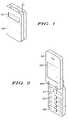
- FIG. 1is a diagram illustrating a typical handheld device.
- FIG. 2is a diagram illustrating further details of the handheld device of FIG. 1 .
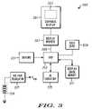
- FIG. 3is a block diagram illustrating components of the handheld device of FIG. 1 .
- FIG. 4is a block diagram in accordance with a preferred embodiment of the present invention.
- FIG. 5is a flow diagram of device operation in accordance with a preferred embodiment of the present invention.
- a handheld device in stand-by modeswitches to a partial graphical display mode.
- a display module and a memory element used in conjunction with the partial graphical displayare optimized such that data lines are clocked simultaneously. Because data lines are clocked simultaneously, multiple pixels may be refreshed simultaneously. Thus, the refresh clock frequency is reduced during partial display mode, which results in reduction of battery drain and improved operation time.
- a first aspect of the present inventionis a circuit for reducing the power consumption of a graphical display comprising a memory component.
- the memory componenthas a full display mode corresponding to a first clock cycle and a partial display mode corresponding to a second clock cycle different from the first clock cycle.
- the memory componentoutputs a single pixel per clock cycle for the full display mode and outputs a plurality of pixels per clock cycle for the partial display mode.
- a second aspect of the present inventionis a display controller.
- the memory componenthas a bit width suitable for storing color bit information for a number of pixels within the bit width, and is capable of transferring the color bit information for the number of pixels in parallel.
- the display controlleris capable of receiving the color bit information for the number of pixels in parallel from the memory component, and transmitting the color bit information in parallel.
- a third aspect of the present inventionis a display module comprising first and second signal inputs.
- the first signal inputreceives a partial mode signal.
- the second signal inputreceives color bit information for a plurality of pixels in parallel.
- a fourth aspect of the present inventionis a battery-powered device comprising a graphical display, a memory component and a display controller.
- the memory componenthas a bit width suitable for storing color bit information for a number of pixels within the bit width, and is capable of transferring the color bit information for the number of pixels in parallel.
- the display controlleris capable of receiving the color bit information for the number of pixels in parallel from the memory component, and transmitting the color bit information in parallel.
- a fifth aspect of the present inventionis a method of implementing a partial display mode for a battery-powered device.
- the battery-powered deviceis switched into stand-by mode and a display is switched into partial display mode.
- a reduced number of color representation bits per pixelare stored in a memory during partial display mode.
- a clock frequencyis then reduced by a factor related to the number of pixels.
- pixel datais transmitted for the number of pixels in parallel from memory to a controller.
- the pixel datais transmitted in parallel from the controller to the display.
- the present inventionrelates to an apparatus and method for reducing the power consumed by a graphics accelerator.
- a handheld device having a displayis switched into a stand-by mode based upon a detected level of user activity.
- the displaywhen in stand-by mode and therefore partial display mode, utilizes a clock frequency that is determined by the number of horizontal and vertical pixels in the display, and the required refresh rate.
- the displayutilizes a reduced color depth per pixel during partial display mode.
- an eight-color implementationrequires 3 bits per pixel such that red, green and blue require 3 bit representation each.
- an LCD controlleris connected to an LCD driver via data and control lines, such as 18 data lines and 3 control lines. Each data line may be used to transmit one bit of color information from the LCD controller to the LCD driver.
- the clock refresh frequencymay be reduced if several color information bits are clocked and thereby transmitted from memory to the LCD controller simultaneously.
- the memory block used by the LCD controller architecturehas a width appropriate for storing bits, such as 18 bits.
- a memory block of 18 ⁇ 939 bitswould be required to accommodate the exemplary partial display provided herein, in accordance with preferred embodiments of the present invention.
- the clock refresh frequency for the partial displaymay thereby be reduced.
- FIGS. 1 and 2illustrate a handheld device in accordance with preferred embodiments of the present invention.
- the devicemay comprise a “clamshell” design in which cover 101 is connected to the main body 205 via a hinge connection 209 .
- the cover 101may further comprise dual displays, an external display 103 and an internal display 207 .
- the internal displaymay be viewable by a user only when cover 101 is in an open position as illustrated in FIG. 2 .
- the handheld devicemay further comprise a keypad 213 , and a joystick control 211 , both of which facilitate user entry.
- the output displayed by the handheld device in response to a user entrymay be displayed on internal display 207 .
- Standard indicationssuch as time, date, and received network signal strength, may be shown on external display 103 when cover 101 is in the closed position as shown in FIG. 1 .
- the external display 103may be disabled, and the standard indications may then be provided on internal display 207 .
- internal display 207is typically larger than external display 103 , internal display 207 may show other indications not shown on external display 103 because of space limitations.
- the main body 205may incorporate a display.
- cover 101would not have an external display but would have an aperture instead.
- the aperturewould be sufficient to allow a user to view the display on the main body 205 , when the cover 101 is in the closed position. Any standard indications would be shown on the display incorporated into the main body 205 .
- a third device configuration that may be utilized in preferred embodiments of the present inventionis a “candy bar” design.
- the main body of the devicedoes not have a cover and comprises a single display, keypad, and joystick control.
- the single displaywould normally provide standard indications to the user whenever the phone is powered on.
- the present inventionis not limited to such devices. Because the object of the present invention is to reduce battery power consumed by the elements of a graphical display, any handheld device incorporating such a display would derive benefit from the incorporation of preferred embodiments.
- FIG. 3provides a block diagram illustrating components of a handheld device 300 , in accordance with preferred embodiments. It should be noted that FIG. 3 is for illustrative purposes only and is applicable to any of the physical device configurations described above, such as the device illustrated by FIGS. 1 and 2 . FIG. 3 illustrates the typical components of a handheld device.
- the handheld device 300derives its power from a battery 319 , which is connectively coupled to a voltage regulator 317 .
- Voltage regulator 317is connectively coupled to a voltage supply bus, V sup , which is further coupled to all circuit elements of the device 300 .
- Device 300further comprises means of user input 309 , such as a keypad, and joystick control. Therefore, user input 309 , as illustrated in FIG. 3 , represents a plurality of user input mechanisms.
- User input 309is connectively coupled to a central processing unit, CPU 313 .
- CPU 313may also be connected to a radio frequency (RF) circuitry 315 , such that device 300 may receive signals from, and communicate with, a network (not shown).
- RFradio frequency
- Device 300also incorporates sensors 321 to detect various states of the device.
- Sensors block 321 as illustrated in FIG. 3represents a plurality of sensing mechanisms.
- the circuitry of sensors 321may incorporate a light detection means, such that the display brightness is adjusted based upon a detected level of light.
- sensors 321may incorporate an activity detection means to detect user activity with respect to user input 309 .
- Another device state that may be detected by sensors 321 in preferred embodiments of the present inventionis device position.
- the sensorsmay detect when the device is horizontally positioned with respect to the ground, such as when the device is placed flat on the surface of a table or desk.
- a user's activity with respect to user input 309may be detected and measured by sensors 321 and used, individually, in addition to, or in combination with other detected states, to control the state of the graphical display 301 .
- Graphical display 301is a liquid crystal display (LCD) and is comprised of a number of horizontal and vertical pixels. Graphical display 301 is also partitioned into a partial display 303 suitable for displaying standard indications of device 300 even when the remainder of display 301 is inactive. Graphical display 301 also requires display drivers 307 which are connectively coupled to graphical display 301 , and in some preferred embodiments may be integrated with graphical display 301 so as to form a display module.
- LCDliquid crystal display
- the display drivers 307are connectively coupled to CPU 313 via data and control lines 305 .
- data and control lines 305comprise 18 data lines and 3 control lines connectively coupling CPU 313 to display drivers 307 .
- Display image memory 311is also connectively coupled to CPU 313 and is used to store pixel data of the graphical display 301 for purposes of rendering graphical images on graphical display 301 .
- display image memory 311is integrated with display drivers 307 , such that display drivers 307 comprise drivers and display image memory 311 .
- FIG. 4illustrates further details of the device 300 components in accordance with preferred embodiments of the present invention.
- a graphics accelerator 401is utilized to off load the main processor from the tasks required for rendering images on graphical display 301 .
- the graphics acceleratorcomprises an LCD controller 403 which is connectively coupled to display drivers 307 via data and control lines 305 . Further connected to the LCD controller 403 are memory 405 and graphics engine 407 , which performs the processing tasks required for rendering images on graphical display 301 .
- Graphical accelerator 401receives a clock signal 411 via a timing logic 415 .
- memory 405may have one of three different configurations for preferred embodiments of the present invention. In a first configuration, a small portion of the main memory of device 300 is dedicated for partial display mode. In a second configuration, device 300 incorporates a memory used exclusively for partial display mode operation. Lastly, various memory bit widths may be employed, as convenient for any of the above configurations.
- state control logic 419is for illustrative purposes only and represents a control signal used by the main processor to determine the clock signal 411 frequency transmitted to graphics accelerator 401 .
- the sensors 321transmit a state indication to CPU 313 , which then implements state-control logic 419 to determine the position of clock-switch 413 .
- clock-switch 413as illustrated in FIG. 4 , is only for purposes of showing the basic logical operation of device 300 and not to designate a specific implementation. Rather, implementation of state control logic 419 and clock-switch 413 represent any suitable implementation.
- clock-switch 413In normal operation of device 300 , specifically when device 300 is not in a stand-by mode, clock-switch 413 is in position “B” such that timing logic 415 provides a clock signal 411 determined by the total number of horizontal and vertical display pixels of display 301 , and a required refresh rate.
- timing logic 415 and division block 417are for purposes of illustrating logical operation only and are not a limitation on the implementation of such logic. Rather, the actual implementation of timing logic 415 and division block 417 may be done in any suitable manner.
- the graphical display 301is likewise switched into a partial display mode such that only partial display 303 is active.
- data and control lines 305comprise an additional control line specifically such that LCD controller 403 may transmit a control signal to display drivers 307 to cause display drivers 307 to operate in a partial mode.
- the graphical display modulewhich comprises graphical display 301 and display drivers 307 , is optimized in preferred embodiments, such that the data bits for partial display 303 pixels, such as six partial display pixels, may be received from LCD controller 403 , in a parallel and therefore simultaneous manner.
- memory 405is optimized in preferred embodiments to have a width such that the fractional clock signal 411 received by graphics accelerator 401 facilitates the transfer of a full width of bits to the graphical display module.
- the memory of the preferred embodimentsbe 18 bits in width. Smaller bit widths, such as for example 15 bits, may also be used in accordance with preferred embodiments of the present invention.
- FIG. 5is a block diagram illustrating basic operation in accordance with preferred embodiments of the present invention.
- a handheld deviceswitches into stand-by mode and thus into a partial display mode.
- a control signalis transmitted from an LCD controller to a display module or to display drivers to cause the display module or display drivers to operate in a partial display mode.
- operation of the displayutilizes, for example, 8-colors and therefore requires 3 color data bits per pixel.
- the clock frequency required for partial modeis reduced in proportion to the number of bits being simultaneously clocked from memory to the display module or display drivers.
- Block 509indicates the use of a special memory block for storage of partial display pixel data; either a configured portion of main memory, or a special memory dedicated to partial display mode.
- a special memory blockfor storage of partial display pixel data; either a configured portion of main memory, or a special memory dedicated to partial display mode.
- multiple pixelsare clocked simultaneously from the memory storage to the display.
- poweris maintained to the partial display mode memory block, and to the partial display in accordance with preferred embodiments.
Landscapes
- Engineering & Computer Science (AREA)
- Chemical & Material Sciences (AREA)
- Physics & Mathematics (AREA)
- Computer Hardware Design (AREA)
- General Physics & Mathematics (AREA)
- Theoretical Computer Science (AREA)
- Combustion & Propulsion (AREA)
- Mechanical Engineering (AREA)
- General Engineering & Computer Science (AREA)
- Crystallography & Structural Chemistry (AREA)
- Control Of Indicators Other Than Cathode Ray Tubes (AREA)
- Liquid Crystal Display Device Control (AREA)
Abstract
Description
32×176=5632 Partial Display Pixels
15 Hz×5632 (Partial Display Pixels)=84.48 kHz
(Number of Partial Display Pixels)×(Number of color data bits per pixel).
5632×3=16896 bits
16986/18 columns=939 rows
Claims (6)
Priority Applications (3)
| Application Number | Priority Date | Filing Date | Title |
|---|---|---|---|
| US10/427,784US7388579B2 (en) | 2003-05-01 | 2003-05-01 | Reduced power consumption for a graphics accelerator and display |
| CNB2004100456966ACN100416648C (en) | 2003-05-01 | 2004-04-30 | Reduced power consumption for a graphics accelerator and display |
| KR1020040030824AKR100742795B1 (en) | 2003-05-01 | 2004-05-01 | Reduced power consumption for a graphics accelerator and display |
Applications Claiming Priority (1)
| Application Number | Priority Date | Filing Date | Title |
|---|---|---|---|
| US10/427,784US7388579B2 (en) | 2003-05-01 | 2003-05-01 | Reduced power consumption for a graphics accelerator and display |
Publications (2)
| Publication Number | Publication Date |
|---|---|
| US20040217954A1 US20040217954A1 (en) | 2004-11-04 |
| US7388579B2true US7388579B2 (en) | 2008-06-17 |
Family
ID=33310256
Family Applications (1)
| Application Number | Title | Priority Date | Filing Date |
|---|---|---|---|
| US10/427,784Expired - LifetimeUS7388579B2 (en) | 2003-05-01 | 2003-05-01 | Reduced power consumption for a graphics accelerator and display |
Country Status (3)
| Country | Link |
|---|---|
| US (1) | US7388579B2 (en) |
| KR (1) | KR100742795B1 (en) |
| CN (1) | CN100416648C (en) |
Cited By (10)
| Publication number | Priority date | Publication date | Assignee | Title |
|---|---|---|---|---|
| US20070002168A1 (en)* | 2005-06-29 | 2007-01-04 | Maximino Vasquez | Techniques to switch between video display modes |
| US20070091050A1 (en)* | 2005-10-20 | 2007-04-26 | Yukari Katayama | Display device |
| US20070109298A1 (en)* | 2005-06-29 | 2007-05-17 | Baback Elmieh | Offline optimization pipeline for 3D content in embedded devices |
| US20080030615A1 (en)* | 2005-06-29 | 2008-02-07 | Maximino Vasquez | Techniques to switch between video display modes |
| US20100277409A1 (en)* | 2008-01-22 | 2010-11-04 | Kouji Yamamoto | Terminal, method for controlling display device thereof, and recording medium where program for controlling display is recorded |
| US20110185369A1 (en)* | 2010-01-25 | 2011-07-28 | Canon Kabushiki Kaisha | Refresh of auxiliary display |
| US20150193062A1 (en)* | 2014-01-06 | 2015-07-09 | Nvidia Corporation | Method and apparatus for buffering sensor input in a low power system state |
| US9293119B2 (en) | 2014-01-06 | 2016-03-22 | Nvidia Corporation | Method and apparatus for optimizing display updates on an interactive display device |
| US10430918B2 (en) | 2014-07-23 | 2019-10-01 | Samsung Electronics Co., Ltd. | Display driver, display system, and method of operating the display driver |
| US11320853B2 (en) | 2016-03-14 | 2022-05-03 | Sharp Nec Display Solutions, Ltd. | Image transmission apparatus, image transmission system, and method of controlling image transmission apparatus |
Families Citing this family (59)
| Publication number | Priority date | Publication date | Assignee | Title |
|---|---|---|---|---|
| TW592365U (en)* | 2003-05-21 | 2004-06-11 | Richtek Technology Corp | Light source control chip of dual-display handheld device |
| US20060007237A1 (en)* | 2004-07-08 | 2006-01-12 | Eric Jeffrey | Apparatuses and methods for sharing a memory between display data and compressed display data |
| KR20060015946A (en)* | 2004-08-16 | 2006-02-21 | 삼성전자주식회사 | Display device and display system |
| CN100370512C (en)* | 2005-03-25 | 2008-02-20 | 华为技术有限公司 | A method and device for displaying information |
| US7730336B2 (en) | 2006-05-30 | 2010-06-01 | Ati Technologies Ulc | Device having multiple graphics subsystems and reduced power consumption mode, software and methods |
| US8225231B2 (en) | 2005-08-30 | 2012-07-17 | Microsoft Corporation | Aggregation of PC settings |
| WO2007112021A2 (en)* | 2006-03-23 | 2007-10-04 | One Laptop Per Child Association, Inc. | Self-refreshing display controller for a display device in a computational unit |
| US8994700B2 (en) | 2006-03-23 | 2015-03-31 | Mark J. Foster | Artifact-free transitions between dual display controllers |
| US20070285428A1 (en)* | 2006-03-23 | 2007-12-13 | One Laptop Per Child Association, Inc. | Self-refreshing display controller for a display device in a computational unit |
| WO2007112019A2 (en)* | 2006-03-23 | 2007-10-04 | One Laptop Per Child Association, Inc. | Artifact-free transitions between dual display controllers |
| TWI437433B (en)* | 2006-03-23 | 2014-05-11 | One Laptop Per Child Ass Inc | Self-refreshing display controller for display devices in a computational unit |
| US20080303836A1 (en)* | 2007-06-01 | 2008-12-11 | National Semiconductor Corporation | Video display driver with partial memory control |
| US20090058842A1 (en)* | 2007-09-04 | 2009-03-05 | Apple Inc. | Devices and methods for controlling a display to conserve power |
| WO2009070280A1 (en)* | 2007-11-26 | 2009-06-04 | One Laptop Per Child Association, Inc. | Method and apparatus for maintaining connectivity in a network |
| CN101598966A (en)* | 2008-06-06 | 2009-12-09 | 深圳富泰宏精密工业有限公司 | The contactor control device and the control method thereof that show two pictures |
| US8411046B2 (en) | 2008-10-23 | 2013-04-02 | Microsoft Corporation | Column organization of content |
| US8385952B2 (en) | 2008-10-23 | 2013-02-26 | Microsoft Corporation | Mobile communications device user interface |
| US8086275B2 (en) | 2008-10-23 | 2011-12-27 | Microsoft Corporation | Alternative inputs of a mobile communications device |
| US8175653B2 (en)* | 2009-03-30 | 2012-05-08 | Microsoft Corporation | Chromeless user interface |
| US8238876B2 (en) | 2009-03-30 | 2012-08-07 | Microsoft Corporation | Notifications |
| US8355698B2 (en)* | 2009-03-30 | 2013-01-15 | Microsoft Corporation | Unlock screen |
| US8269736B2 (en) | 2009-05-22 | 2012-09-18 | Microsoft Corporation | Drop target gestures |
| US8836648B2 (en) | 2009-05-27 | 2014-09-16 | Microsoft Corporation | Touch pull-in gesture |
| US20120159395A1 (en) | 2010-12-20 | 2012-06-21 | Microsoft Corporation | Application-launching interface for multiple modes |
| US20120159383A1 (en) | 2010-12-20 | 2012-06-21 | Microsoft Corporation | Customization of an immersive environment |
| US8689123B2 (en) | 2010-12-23 | 2014-04-01 | Microsoft Corporation | Application reporting in an application-selectable user interface |
| US8612874B2 (en) | 2010-12-23 | 2013-12-17 | Microsoft Corporation | Presenting an application change through a tile |
| US9423951B2 (en) | 2010-12-31 | 2016-08-23 | Microsoft Technology Licensing, Llc | Content-based snap point |
| US9383917B2 (en) | 2011-03-28 | 2016-07-05 | Microsoft Technology Licensing, Llc | Predictive tiling |
| TWI442312B (en)* | 2011-04-20 | 2014-06-21 | Wistron Corp | Method for accelerating speed of refreshing image screen of display-panel |
| US9658766B2 (en) | 2011-05-27 | 2017-05-23 | Microsoft Technology Licensing, Llc | Edge gesture |
| US8893033B2 (en) | 2011-05-27 | 2014-11-18 | Microsoft Corporation | Application notifications |
| US9104307B2 (en) | 2011-05-27 | 2015-08-11 | Microsoft Technology Licensing, Llc | Multi-application environment |
| US20120304132A1 (en) | 2011-05-27 | 2012-11-29 | Chaitanya Dev Sareen | Switching back to a previously-interacted-with application |
| US9158445B2 (en) | 2011-05-27 | 2015-10-13 | Microsoft Technology Licensing, Llc | Managing an immersive interface in a multi-application immersive environment |
| US9104440B2 (en) | 2011-05-27 | 2015-08-11 | Microsoft Technology Licensing, Llc | Multi-application environment |
| US8687023B2 (en) | 2011-08-02 | 2014-04-01 | Microsoft Corporation | Cross-slide gesture to select and rearrange |
| US20130057587A1 (en) | 2011-09-01 | 2013-03-07 | Microsoft Corporation | Arranging tiles |
| US10353566B2 (en) | 2011-09-09 | 2019-07-16 | Microsoft Technology Licensing, Llc | Semantic zoom animations |
| US9557909B2 (en) | 2011-09-09 | 2017-01-31 | Microsoft Technology Licensing, Llc | Semantic zoom linguistic helpers |
| US8922575B2 (en) | 2011-09-09 | 2014-12-30 | Microsoft Corporation | Tile cache |
| US8933952B2 (en) | 2011-09-10 | 2015-01-13 | Microsoft Corporation | Pre-rendering new content for an application-selectable user interface |
| US9244802B2 (en) | 2011-09-10 | 2016-01-26 | Microsoft Technology Licensing, Llc | Resource user interface |
| US9146670B2 (en) | 2011-09-10 | 2015-09-29 | Microsoft Technology Licensing, Llc | Progressively indicating new content in an application-selectable user interface |
| US9223472B2 (en) | 2011-12-22 | 2015-12-29 | Microsoft Technology Licensing, Llc | Closing applications |
| US9128605B2 (en) | 2012-02-16 | 2015-09-08 | Microsoft Technology Licensing, Llc | Thumbnail-image selection of applications |
| KR102059501B1 (en) | 2012-08-22 | 2019-12-27 | 삼성디스플레이 주식회사 | Display device and driving method thereof |
| KR101997776B1 (en)* | 2012-10-16 | 2019-07-08 | 삼성전자주식회사 | Method for reducing for consumption power of display unit and an electronic device thereof |
| US9450952B2 (en) | 2013-05-29 | 2016-09-20 | Microsoft Technology Licensing, Llc | Live tiles without application-code execution |
| CN105359094A (en) | 2014-04-04 | 2016-02-24 | 微软技术许可有限责任公司 | Extensible Application Representation |
| KR102107275B1 (en) | 2014-04-10 | 2020-05-06 | 마이크로소프트 테크놀로지 라이센싱, 엘엘씨 | Collapsible shell cover for computing device |
| KR20160143784A (en) | 2014-04-10 | 2016-12-14 | 마이크로소프트 테크놀로지 라이센싱, 엘엘씨 | Slider cover for computing devices |
| US10678412B2 (en) | 2014-07-31 | 2020-06-09 | Microsoft Technology Licensing, Llc | Dynamic joint dividers for application windows |
| US10254942B2 (en) | 2014-07-31 | 2019-04-09 | Microsoft Technology Licensing, Llc | Adaptive sizing and positioning of application windows |
| US10592080B2 (en) | 2014-07-31 | 2020-03-17 | Microsoft Technology Licensing, Llc | Assisted presentation of application windows |
| US10642365B2 (en) | 2014-09-09 | 2020-05-05 | Microsoft Technology Licensing, Llc | Parametric inertia and APIs |
| CN106662891B (en) | 2014-10-30 | 2019-10-11 | 微软技术许可有限责任公司 | Multi-configuration input equipment |
| CN115985223B (en) | 2023-03-21 | 2023-08-25 | 惠科股份有限公司 | Display device and driving method thereof |
| CN116343717B (en)* | 2023-03-21 | 2024-07-09 | 惠科股份有限公司 | Display device and driving method thereof |
Citations (10)
| Publication number | Priority date | Publication date | Assignee | Title |
|---|---|---|---|---|
| US5502837A (en)* | 1992-08-11 | 1996-03-26 | Sun Microsystems, Inc. | Method and apparatus for clocking variable pixel frequencies and pixel depths in a memory display interface |
| US5524249A (en)* | 1994-01-27 | 1996-06-04 | Compaq Computer Corporation | Video subsystem power management apparatus and method |
| US5796391A (en)* | 1996-10-24 | 1998-08-18 | Motorola, Inc. | Scaleable refresh display controller |
| US5867140A (en) | 1996-11-27 | 1999-02-02 | Motorola, Inc. | Display system and circuit therefor |
| US6320564B1 (en)* | 1992-02-26 | 2001-11-20 | Hitachi, Ltd. | Multiple-tone display system |
| US6429840B1 (en)* | 1999-09-27 | 2002-08-06 | Citizen Watch Co., Ltd. | Method of driving color liquid crystal display panel and method of controlling display of timepiece |
| US20020111200A1 (en)* | 2001-02-09 | 2002-08-15 | Susumu Nikawa | Power reducing apparatus and method for portable terminal equipped with display unit |
| US6476800B2 (en)* | 1998-03-23 | 2002-11-05 | International Business Machines Corporation | Method and apparatus for adjusting video refresh rate in response to power mode changes in order to conserve power |
| US20020190941A1 (en)* | 2001-06-13 | 2002-12-19 | Rohm Co., Ltd. | Display driving device, display apparatus, and method of driving the same |
| US6734866B1 (en)* | 2000-09-28 | 2004-05-11 | Rockwell Automation Technologies, Inc. | Multiple adapting display interface |
Family Cites Families (6)
| Publication number | Priority date | Publication date | Assignee | Title |
|---|---|---|---|---|
| JPH11202090A (en)* | 1998-01-08 | 1999-07-30 | Taiheiyo Cement Corp | Neutron shield body and production method for it |
| EP1577874A3 (en) | 1998-02-09 | 2006-09-13 | Seiko Epson Corporation | Electrooptical apparatus and driving method therefor, liquid crystal display apparatus and driving method therefor, electrooptical apparatus and driving circuit therefor, and electronic equipment |
| KR100291035B1 (en)* | 1999-01-13 | 2001-05-15 | 윤종용 | Color lcd interfacing circuit for portable radio terminal equipment |
| JP5019668B2 (en) | 2000-09-18 | 2012-09-05 | 三洋電機株式会社 | Display device and control method thereof |
| JP3570382B2 (en) | 2001-01-26 | 2004-09-29 | 日本電気株式会社 | Power saving graphic control circuit |
| JP4638117B2 (en) | 2002-08-22 | 2011-02-23 | シャープ株式会社 | Display device and driving method thereof |
- 2003
- 2003-05-01USUS10/427,784patent/US7388579B2/ennot_activeExpired - Lifetime
- 2004
- 2004-04-30CNCNB2004100456966Apatent/CN100416648C/ennot_activeExpired - Lifetime
- 2004-05-01KRKR1020040030824Apatent/KR100742795B1/ennot_activeExpired - Lifetime
Patent Citations (10)
| Publication number | Priority date | Publication date | Assignee | Title |
|---|---|---|---|---|
| US6320564B1 (en)* | 1992-02-26 | 2001-11-20 | Hitachi, Ltd. | Multiple-tone display system |
| US5502837A (en)* | 1992-08-11 | 1996-03-26 | Sun Microsystems, Inc. | Method and apparatus for clocking variable pixel frequencies and pixel depths in a memory display interface |
| US5524249A (en)* | 1994-01-27 | 1996-06-04 | Compaq Computer Corporation | Video subsystem power management apparatus and method |
| US5796391A (en)* | 1996-10-24 | 1998-08-18 | Motorola, Inc. | Scaleable refresh display controller |
| US5867140A (en) | 1996-11-27 | 1999-02-02 | Motorola, Inc. | Display system and circuit therefor |
| US6476800B2 (en)* | 1998-03-23 | 2002-11-05 | International Business Machines Corporation | Method and apparatus for adjusting video refresh rate in response to power mode changes in order to conserve power |
| US6429840B1 (en)* | 1999-09-27 | 2002-08-06 | Citizen Watch Co., Ltd. | Method of driving color liquid crystal display panel and method of controlling display of timepiece |
| US6734866B1 (en)* | 2000-09-28 | 2004-05-11 | Rockwell Automation Technologies, Inc. | Multiple adapting display interface |
| US20020111200A1 (en)* | 2001-02-09 | 2002-08-15 | Susumu Nikawa | Power reducing apparatus and method for portable terminal equipped with display unit |
| US20020190941A1 (en)* | 2001-06-13 | 2002-12-19 | Rohm Co., Ltd. | Display driving device, display apparatus, and method of driving the same |
Cited By (14)
| Publication number | Priority date | Publication date | Assignee | Title |
|---|---|---|---|---|
| US8026910B2 (en)* | 2005-06-29 | 2011-09-27 | Qualcomm Incorporated | Offline optimization pipeline for 3D content in embedded devices |
| US20070002168A1 (en)* | 2005-06-29 | 2007-01-04 | Maximino Vasquez | Techniques to switch between video display modes |
| US20070109298A1 (en)* | 2005-06-29 | 2007-05-17 | Baback Elmieh | Offline optimization pipeline for 3D content in embedded devices |
| US20080030615A1 (en)* | 2005-06-29 | 2008-02-07 | Maximino Vasquez | Techniques to switch between video display modes |
| US8072443B2 (en) | 2005-06-29 | 2011-12-06 | Intel Corporation | Techniques to switch between video display modes |
| US8154498B2 (en)* | 2005-10-20 | 2012-04-10 | Hitachi Displays, Ltd. | Display device |
| US20070091050A1 (en)* | 2005-10-20 | 2007-04-26 | Yukari Katayama | Display device |
| US20100277409A1 (en)* | 2008-01-22 | 2010-11-04 | Kouji Yamamoto | Terminal, method for controlling display device thereof, and recording medium where program for controlling display is recorded |
| US20110185369A1 (en)* | 2010-01-25 | 2011-07-28 | Canon Kabushiki Kaisha | Refresh of auxiliary display |
| US9293119B2 (en) | 2014-01-06 | 2016-03-22 | Nvidia Corporation | Method and apparatus for optimizing display updates on an interactive display device |
| US20150193062A1 (en)* | 2014-01-06 | 2015-07-09 | Nvidia Corporation | Method and apparatus for buffering sensor input in a low power system state |
| US9383851B2 (en)* | 2014-01-06 | 2016-07-05 | Nvidia Corporation | Method and apparatus for buffering sensor input in a low power system state |
| US10430918B2 (en) | 2014-07-23 | 2019-10-01 | Samsung Electronics Co., Ltd. | Display driver, display system, and method of operating the display driver |
| US11320853B2 (en) | 2016-03-14 | 2022-05-03 | Sharp Nec Display Solutions, Ltd. | Image transmission apparatus, image transmission system, and method of controlling image transmission apparatus |
Also Published As
| Publication number | Publication date |
|---|---|
| US20040217954A1 (en) | 2004-11-04 |
| KR20040094646A (en) | 2004-11-10 |
| KR100742795B1 (en) | 2007-07-25 |
| CN100416648C (en) | 2008-09-03 |
| CN1551098A (en) | 2004-12-01 |
Similar Documents
| Publication | Publication Date | Title |
|---|---|---|
| US7388579B2 (en) | Reduced power consumption for a graphics accelerator and display | |
| US5841431A (en) | Application of split- and dual-screen LCD panel design in cellular phones | |
| JP4183222B2 (en) | Power saving driving method for mobile phone | |
| KR100260695B1 (en) | Display system and circuit therefor | |
| US7019738B2 (en) | Display device and its control method | |
| US7016703B2 (en) | Portable information apparatus for displaying information in a folded state | |
| US11048109B2 (en) | Display module, display device, and method for controlling same | |
| US7567092B2 (en) | Liquid crystal display driver including test pattern generating circuit | |
| US20040189566A1 (en) | Display device | |
| US20130127695A1 (en) | Display Control Drive Device and Display System | |
| JP2004126257A (en) | Display device for portable electronic appliance | |
| US20090009510A1 (en) | Data line driving circuit, display device and method of driving data line | |
| KR20060047943A (en) | Display panel drive | |
| JP2005326859A (en) | Dual panel drive system and drive method | |
| EP1662468B1 (en) | Active matrix oled display device and electronic apparatus | |
| JP2005331916A (en) | Display device and driving method thereof | |
| US20050001857A1 (en) | Image display apparatus and electronic apparatus | |
| JP3596507B2 (en) | Display memory, driver circuit, and display | |
| JP2004109595A (en) | Display device and its driving method | |
| US20020113762A1 (en) | Data driving circuit of liquid crystal display device | |
| JP4429342B2 (en) | Power saving driving method for mobile phone | |
| CN100380435C (en) | display device | |
| JP2006119620A (en) | Multiple display apparatus and multiple display control method therefor | |
| US7518599B2 (en) | Display control device and method | |
| JP2008268976A (en) | Display device and driving method thereof |
Legal Events
| Date | Code | Title | Description |
|---|---|---|---|
| AS | Assignment | Owner name:MOTOROLA, INC., ILLINOIS Free format text:ASSIGNMENT OF ASSIGNORS INTEREST;ASSIGNORS:O'GORMAN, PATRICK;FOO, KEN;REEL/FRAME:014036/0052;SIGNING DATES FROM 20030425 TO 20030430 | |
| STCF | Information on status: patent grant | Free format text:PATENTED CASE | |
| AS | Assignment | Owner name:MOTOROLA MOBILITY, INC, ILLINOIS Free format text:ASSIGNMENT OF ASSIGNORS INTEREST;ASSIGNOR:MOTOROLA, INC;REEL/FRAME:025673/0558 Effective date:20100731 | |
| FPAY | Fee payment | Year of fee payment:4 | |
| AS | Assignment | Owner name:MOTOROLA MOBILITY LLC, ILLINOIS Free format text:CHANGE OF NAME;ASSIGNOR:MOTOROLA MOBILITY, INC.;REEL/FRAME:029216/0282 Effective date:20120622 | |
| AS | Assignment | Owner name:GOOGLE TECHNOLOGY HOLDINGS LLC, CALIFORNIA Free format text:ASSIGNMENT OF ASSIGNORS INTEREST;ASSIGNOR:MOTOROLA MOBILITY LLC;REEL/FRAME:034449/0001 Effective date:20141028 | |
| FPAY | Fee payment | Year of fee payment:8 | |
| MAFP | Maintenance fee payment | Free format text:PAYMENT OF MAINTENANCE FEE, 12TH YEAR, LARGE ENTITY (ORIGINAL EVENT CODE: M1553); ENTITY STATUS OF PATENT OWNER: LARGE ENTITY Year of fee payment:12 |