US7388539B2 - Carrier track loop for GNSS derived attitude - Google Patents
Carrier track loop for GNSS derived attitudeDownload PDFInfo
- Publication number
- US7388539B2 US7388539B2US11/253,871US25387105AUS7388539B2US 7388539 B2US7388539 B2US 7388539B2US 25387105 AUS25387105 AUS 25387105AUS 7388539 B2US7388539 B2US 7388539B2
- Authority
- US
- United States
- Prior art keywords
- tracking device
- phase
- carrier
- tracking
- antenna
- Prior art date
- Legal status (The legal status is an assumption and is not a legal conclusion. Google has not performed a legal analysis and makes no representation as to the accuracy of the status listed.)
- Active, expires
Links
- 238000000034methodMethods0.000claimsabstractdescription44
- 238000004891communicationMethods0.000claimsabstractdescription15
- 238000004590computer programMethods0.000claimsdescription7
- 230000006870functionEffects0.000description11
- 230000004044responseEffects0.000description11
- 230000001133accelerationEffects0.000description8
- 238000010586diagramMethods0.000description8
- 230000000694effectsEffects0.000description8
- 230000008901benefitEffects0.000description6
- 238000005259measurementMethods0.000description5
- 230000010363phase shiftEffects0.000description5
- 230000001934delayEffects0.000description4
- 230000000737periodic effectEffects0.000description4
- 230000008569processEffects0.000description4
- 238000012545processingMethods0.000description4
- 238000005070samplingMethods0.000description4
- 230000001360synchronised effectEffects0.000description4
- 230000035508accumulationEffects0.000description3
- 238000009825accumulationMethods0.000description3
- 238000006243chemical reactionMethods0.000description3
- 230000007704transitionEffects0.000description3
- 238000013459approachMethods0.000description2
- 230000003416augmentationEffects0.000description2
- 230000008859changeEffects0.000description2
- 239000002131composite materialSubstances0.000description2
- 230000003287optical effectEffects0.000description2
- 230000003595spectral effectEffects0.000description2
- 230000007480spreadingEffects0.000description2
- 230000018199S phaseEffects0.000description1
- LWZFANDGMFTDAV-BURFUSLBSA-N[(2r)-2-[(2r,3r,4s)-3,4-dihydroxyoxolan-2-yl]-2-hydroxyethyl] dodecanoateChemical compoundCCCCCCCCCCCC(=O)OC[C@@H](O)[C@H]1OC[C@H](O)[C@H]1OLWZFANDGMFTDAV-BURFUSLBSA-N0.000description1
- 230000002411adverseEffects0.000description1
- 230000003190augmentative effectEffects0.000description1
- 230000009286beneficial effectEffects0.000description1
- 230000005540biological transmissionEffects0.000description1
- 238000012937correctionMethods0.000description1
- 230000008878couplingEffects0.000description1
- 238000010168coupling processMethods0.000description1
- 238000005859coupling reactionMethods0.000description1
- 238000009429electrical wiringMethods0.000description1
- 230000005670electromagnetic radiationEffects0.000description1
- 230000001747exhibiting effectEffects0.000description1
- 238000005562fadingMethods0.000description1
- 239000000835fiberSubstances0.000description1
- 238000001914filtrationMethods0.000description1
- 230000036039immunityEffects0.000description1
- 239000005433ionosphereSubstances0.000description1
- 239000000463materialSubstances0.000description1
- 238000007620mathematical functionMethods0.000description1
- 238000012986modificationMethods0.000description1
- 230000004048modificationEffects0.000description1
- 238000012544monitoring processMethods0.000description1
- 239000002674ointmentSubstances0.000description1
- 230000003252repetitive effectEffects0.000description1
- 235000011067sorbitan monolaureateNutrition0.000description1
- 239000005436troposphereSubstances0.000description1
Images


Classifications
- G—PHYSICS
- G01—MEASURING; TESTING
- G01S—RADIO DIRECTION-FINDING; RADIO NAVIGATION; DETERMINING DISTANCE OR VELOCITY BY USE OF RADIO WAVES; LOCATING OR PRESENCE-DETECTING BY USE OF THE REFLECTION OR RERADIATION OF RADIO WAVES; ANALOGOUS ARRANGEMENTS USING OTHER WAVES
- G01S19/00—Satellite radio beacon positioning systems; Determining position, velocity or attitude using signals transmitted by such systems
- G01S19/38—Determining a navigation solution using signals transmitted by a satellite radio beacon positioning system
- G01S19/39—Determining a navigation solution using signals transmitted by a satellite radio beacon positioning system the satellite radio beacon positioning system transmitting time-stamped messages, e.g. GPS [Global Positioning System], GLONASS [Global Orbiting Navigation Satellite System] or GALILEO
- G01S19/53—Determining attitude
- G—PHYSICS
- G01—MEASURING; TESTING
- G01S—RADIO DIRECTION-FINDING; RADIO NAVIGATION; DETERMINING DISTANCE OR VELOCITY BY USE OF RADIO WAVES; LOCATING OR PRESENCE-DETECTING BY USE OF THE REFLECTION OR RERADIATION OF RADIO WAVES; ANALOGOUS ARRANGEMENTS USING OTHER WAVES
- G01S19/00—Satellite radio beacon positioning systems; Determining position, velocity or attitude using signals transmitted by such systems
- G01S19/38—Determining a navigation solution using signals transmitted by a satellite radio beacon positioning system
- G01S19/39—Determining a navigation solution using signals transmitted by a satellite radio beacon positioning system the satellite radio beacon positioning system transmitting time-stamped messages, e.g. GPS [Global Positioning System], GLONASS [Global Orbiting Navigation Satellite System] or GALILEO
- G01S19/42—Determining position
- G01S19/43—Determining position using carrier phase measurements, e.g. kinematic positioning; using long or short baseline interferometry
- G01S19/44—Carrier phase ambiguity resolution; Floating ambiguity; LAMBDA [Least-squares AMBiguity Decorrelation Adjustment] method
- G—PHYSICS
- G01—MEASURING; TESTING
- G01S—RADIO DIRECTION-FINDING; RADIO NAVIGATION; DETERMINING DISTANCE OR VELOCITY BY USE OF RADIO WAVES; LOCATING OR PRESENCE-DETECTING BY USE OF THE REFLECTION OR RERADIATION OF RADIO WAVES; ANALOGOUS ARRANGEMENTS USING OTHER WAVES
- G01S19/00—Satellite radio beacon positioning systems; Determining position, velocity or attitude using signals transmitted by such systems
- G01S19/38—Determining a navigation solution using signals transmitted by a satellite radio beacon positioning system
- G01S19/39—Determining a navigation solution using signals transmitted by a satellite radio beacon positioning system the satellite radio beacon positioning system transmitting time-stamped messages, e.g. GPS [Global Positioning System], GLONASS [Global Orbiting Navigation Satellite System] or GALILEO
- G01S19/53—Determining attitude
- G01S19/54—Determining attitude using carrier phase measurements; using long or short baseline interferometry
- G01S19/55—Carrier phase ambiguity resolution; Floating ambiguity; LAMBDA [Least-squares AMBiguity Decorrelation Adjustment] method
Definitions
- the inventionrelates generally to precision GNSS location or attitude systems. More specifically, the invention relates to systems that utilize Global Navigation Satellite System (GNSS) signals to infer differential path length of carrier signals arriving at two or more antennas.
- GNSSGlobal Navigation Satellite System
- orientation and reference systemmay be in two dimensions (2D) or in three dimensions (3D).
- terms such as azimuth, heading, elevation, pitch, and inclinationmay be used in place of attitude.
- a GNSSGlobal Navigation Satellite System
- a GNSSincludes a network of satellites that broadcast radio signals, enabling a user to determine the location of a receiving antenna with a high degree of accuracy.
- To determine the attitude of an objectit is simply necessary to determine the position of two or more receiving antennas that have known placements relative to an object.
- GNSS systemsinclude Navstar Global Positioning System (GPS), established by the United States; Globalnaya Navigatsionnay Sputnikovaya Sistema, or Global Orbiting Navigation Satellite System (GLONASS), established by the Russian Federation and similar in concept to GPS; and Galileo, also similar to GPS but created by the European Community and slated for full operational capacity in 2008.
- GPSGlobal Positioning System
- GLONASSGlobal Orbiting Navigation Satellite System
- a Satellite-Based Augmentation Systemmay be incorporated if one that is suitable is available.
- SAASWide Area Augmentation System
- EGNOSEuropean Geostationary Navigation Overlay Service
- GPSwas developed by the United States government and has a constellation of 24 satellites in 6 orbital planes at an altitude of approximately 26,500 km. The first satellite was launched in February 1978. Initial Operational Capability (IOC) for the GPS was declared in December 1993. Each satellite continuously transmits microwave L-band radio signals in two frequency bands, L 1 (1575.42 MHz) and L 2 (1227.6 MHz). The L 1 and L 2 signals are phase shifted, or modulated, by one or more binary codes.
- These binary codesprovide timing patterns relative to the satellite's onboard precision clock (synchronized to other satellites and to a ground reference through a ground-based control segment), in addition to a navigation message giving the precise orbital position of each satellite, clock correction information, and other system parameters.
- the binary codes providing the timing informationare called the C/A Code, or coarse acquisition code, and the P-code, or precise code.
- the C/A Codeis a 1 MHz Pseudo Random Noise (PRN) code modulating the phase of the L 1 signal and repeating every 1023 bits (one millisecond).
- the P-Codeis also a PRN code, but modulates the phase of both the L 1 and L 2 signals and is a 10 MHz code repeating every seven days.
- PRN codesare known patterns that can be compared to internal versions in the receiver.
- the GNSS receiveris able to compute an unambiguous range to each satellite by determining the time-shift necessary to align the internal code to the broadcast code.
- both the C/A Code and the P-Codehave a relatively long “wavelength”—approximately 300 meters (or 1 microsecond) for the C/A Code and 30 meters (or 1/10 microsecond) for the P-Code, positions computed using them have a relatively coarse level of resolution.
- a receivermay take advantage of the carrier component of the L 1 or L 2 signal.
- carrierrefers to the dominant spectral component remaining in the radio signal after the spectral content resulting from the modulating PRN digital codes has been removed (e.g., from the C/A Code and the P-Code).
- the L 1 and L 2 carrier signalshave wavelengths of about 19 centimeters and 24 centimeters, respectively.
- the GPS receiveris able to track these carrier signals and measure the carrier phase to a small fraction of a complete wavelength, permitting range measurement to an accuracy of less than a centimeter.
- DGPSDifferential GPS
- the combination of DGPS with precise measurements of carrier phaseleads to differential position accuracies of less than one centimeter root-mean-squared (i.e., centimeter-level positioning). Such accuracies are sufficient to determine the attitude of an object with 2 or more GPS GNSS antennas, typically spaced from 0.2 meters to 2 meters apart.
- Carrier phase datais available by tracking the carrier phase on either the L 1 or L 2 GPS signal.
- Navigation datais BPSK modulated onto both the L 1 and the L 2 carrier at a 50 Hz rate and, as such, the input carrier phase is subject to a 180 degree phase reversal every 20 milliseconds and the absolute phase can be inverted.
- the data modulationis removed from the carrier by means of a tracking loop known as a Costas loop.
- a Costas loopresults in a 180 degree phase ambiguity. That is, the Costas loop is just as likely to phase lock so that the binary 1's come out as binary 0's, and vice versa.
- the 180 degree phase ambiguityis of concern since it introduces an ambiguity of 1 ⁇ 2 of a carrier wavelength in the measured carrier phase.
- the wavelength of the L 1 carrieris about 19 cm and the 1 ⁇ 2 cycle ambiguity is thus equivalent to 9.5 cm of measured phase.
- the 1 ⁇ 2 cycle ambiguityis resolved by looking at certain data bits within the navigation message that are of a known value. If the bit is inverted over its known value, then the Costas loop is locked to the opposite phase and 1 ⁇ 2 cycle's worth of phase must be added to (or subtracted from) the measured carrier phase in order to maintain whole cycle phase alignment. It is of little consequence whether the 1 ⁇ 2 cycle is added or subtracted from the measured phase since, regardless, a whole cycle ambiguity is still present that must be removed by methods such as those described in U.S. Pat. No. 6,469,663 and/or U.S. patent application Ser. No. 11/243,112, entitled Attitude Determination Exploiting Geometry Constraints, to Whitehead et al., filed Oct. 4, 2005.
- a further complication of a Costas loopis that the probability for a cycle slip is significantly higher when using a Costas loop as opposed to a conventional Phase Lock Loop (PLL). This is because the Costas loop is mathematically equivalent to a squaring loop that tracks the carrier phase at twice the carrier frequency. Phase tracking errors greater than 90 degrees may cause cycle slips in a Costas loop whereas phase errors of up to 180 degrees may be tolerated when using a PLL.
- PLLPhase Lock Loop
- the carrier phases arriving at two or more separate antennasare differenced with one another to create a differential carrier phase.
- the process of taking the differencecancels common mode errors such as satellite clock error and errors caused by propagation delays as the GNSS signal travels through the ionosphere and troposphere.
- a methodis needed that yields common, noise-induced effects in each individually tracked carrier phase so that the common-mode effects cancel in the differential carrier phase.
- a method with the aforementioned propertiesis applied to carrier tracking loops receiving data at two or more antennas that experience roughly similar motion or motion for which relative dynamic effects are low.
- the methodfurther has the ability to track rapid clock-induced carrier phase when a common clock is employed.
- GNSSGlobal Navigation Satellite System
- the sharingis configured to facilitate a commonality in a carrier phase derived in the first and second tracking devices.
- the sharingalso results in a cancellation of the commonality when a difference phase is formed between a carrier phase from the first tracking device and a carrier phase from the second tracking device.
- a system for reducing Global Navigation Satellite System (GNSS) carrier tracking loop ambiguitiescomprising: a first antenna in operable communication with a first tracking device configured to receive a plurality of GNSS satellite signals; and a second antenna in communication with a second tracking device configured to receive a plurality of GNSS satellite signals.
- the first tracking device and the second tracking deviceoperable in at least one GNSS receiver.
- the first tracking device and the second tracking deviceare configured to share data therebetween to facilitate a commonality in a carrier phase derived in the first tracking device and the second tracking device.
- a difference phaseis formed between a carrier phase from the first tracking device and another carrier phase from the second tracking device resulting in a cancellation of the commonality.
- a system for reducing Global Navigation Satellite System (GNSS) carrier tracking loop ambiguitiescomprising: means for receiving a plurality of GNSS satellite signals with a first antenna in operable communication with a first tracking device and a second antenna in communication with a second tracking device in at least one GNSS receiver.
- the systemalso includes means for sharing of data between the first tracking device and the second tracking device, the sharing configured to facilitate a commonality in a carrier phase derived in the first tracking device and the second tracking device. The sharing resulting in a cancellation in the commonality when a difference phase is formed between a carrier phase from the first tracking device and another carrier phase from the second tracking device.
- GNSSGlobal Navigation Satellite System
- Disclosed herein in yet another exemplary embodimentis a storage medium encoded with a machine-readable computer program code, the storage medium including instructions for causing a computing system to implement the abovementioned method for reducing Global Navigation Satellite System (GNSS) carrier tracking loop ambiguities.
- GNSSGlobal Navigation Satellite System
- GNSSGlobal Navigation Satellite System
- the inventionalso features a method for attitude determination or other differential GNSS positioning applications that is effective at reducing the occurrence of 1 ⁇ 2 ambiguities and cycle slips in the differential carrier phase.
- thisis accomplished by sharing information in the Costas tracking loops, designating one tracking device as a master while other slave tracking devices are driven by a carrier discriminator employing the master's in-phase in place of the slave's own in-phase data as is typically done.
- a related inventionyields the benefit of partially canceling common noise-induced effects in differential carrier phase measured between two antennas.
- FIG. 1is a diagram showing the use of GNSS satellites in an attitude determining system
- FIG. 2is a schematic showing an attitude determining system embodiment of an exemplary embodiment of the present invention
- FIG. 3is a block diagram of a carrier phase tracking and measuring system employing a Costas loop
- FIG. 4Ashows true carrier phase error versus the in-phase signal
- FIG. 4Bshows true carrier phase error versus the quadrature-phase signal
- FIG. 4Cshows a carrier discriminator for a Costas loop
- FIG. 4Dshows a carrier discriminator for a conventional Phase Lock Loop
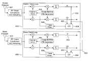
- FIG. 5is a block diagram of master and slave carrier phase track loop that share the master's in-phase data in accordance with an exemplary embodiment
- FIG. 6is a block diagram showing multiple slave carrier phase trackers sharing data from a single master carrier phase tracker
- FIG. 7is a block diagram depicts sharing of data between the Master and Slave carrier phase filters in accordance with an exemplary embodiment.
- FIG. 8is a block diagram depicting sharing of data between the Master and Slave carrier phase filters in accordance with another exemplary embodiment.
- An exemplary embodiment of inventionfeatures a method and system for attitude determination or other GNSS positioning that significantly reduces the adverse effects of cycle slips and, simultaneously, problems resulting from 1 ⁇ 2 cycle phase ambiguities, such as may be encountered when employing a tracking loop, e.g., a phase tracking loop.
- a preferred embodiment of the inventionby way of illustration, is described herein as it may be applied to attitude determination. While a preferred embodiment is shown and described by illustration and reference to attitude determination, it will be appreciated by those skilled in the art that the invention is not limited to attitude determination alone and may be applied to control systems, navigation, and the like, as well as combinations thereof. An embodiment of the invention as described herein may readily be applied to attitude determination as described in commonly assigned U.S. patent application Ser. No. 11/243,112, entitled Attitude Determination Exploiting Geometry Constraints, filed Oct. 4, 2005, the contents of which are incorporated by reference herein in their entirety.
- FIG. 1depicts an exemplary embodiment of an attitude determining system 100 tracking a plurality of GNSS satellites, 101 through 103 .
- the attitude determining hardware system 100includes the use of three antennas to receive GNSS signals. Each satellite broadcasts a radio frequency signal 104 that is picked up by two or more antennas, three of which are shown as 105 through 107 in FIG. 1 . The signal then travels from each antenna into the receiver unit 108 where it is down-converted and digitally sampled so that it may be tracked by the receiver's digital tracking loops.
- timing and navigation informationis readily extracted while tracking the signal, including the phase of a Pseudo Random Noise (PRN) code timing pattern that is modulated on the signal, the phase of the signal's carrier, and navigation data from which the location of the satellite may be computed.
- PRNPseudo Random Noise
- the receiver 108may include, but not be limited to, a processor(s), computer(s), memory, storage, register(s), timing, interrupt(s), communication interface(s), and input/output signal interfaces, and the like, as well as combinations comprising at least one of the foregoing.
- receiver 108may include signal interfaces to enable accurate down-conversion and digitally sampling and tracking of satellite signals as needed to facilitate extracting the various timing and navigation information, including, but not limited to, the phase of the PRN code timing pattern. Additional features of the system 100 , receiver 108 and the like, are thoroughly discussed herein.
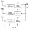
- One exemplary embodiment of an attitude determining system 100 shown in FIG. 2uses a single receiver unit 201 containing multiple synchronized tracking devices, 202 through 204 , with each tracking device associated with exactly one antenna ( 205 , 206 , and 207 ).
- Each tracking device 202 , 203 , and 204is capable of tracking a plurality of satellites e.g., 101 , 102 , and 103 . Twelve or more satellites may be tracked.
- the tracking devices 202 , 203 , and 204serve the function of down converting the received Radio Frequency (RF) signals 104 arriving from the plurality of satellites e.g., 101 , 102 , and 103 , sampling the composite signal, and performing high-speed digital processing on the composite signal (such as correlations with a PRN reference signal) that allow the code and carrier phase of each satellite to be tracked.
- RFRadio Frequency
- An example of such synchronized tracking devices 202 , 203 , and 204is described in commonly assigned U.S. patent application Ser. No. 11/029,809 entitled Method and System for Synchronizing Multiple Tracking Devices For A Geo-location System, filed Jan. 5, 2005, which is a continuation-in-part of U.S. patent application Ser. No.
- Each tracking devicee.g., 202 , 203 , and 204 is connected to a single shared computer processing unit (CPU) 208 .
- the CPU 208sends control commands 210 , 211 , and 212 respectively to the plurality of tracking devices 202 , 203 , and 204 that enable them to track the various GNSS satellites, e.g., 101 , 102 , and 103 .
- the CPU 208receives back from the tracking device code and carrier phase measurements of the various satellite signals.
- a synchronization signal 214sent by the master tracking device 202 to the slave tracking devices 203 and 204 allows the master tracking device 202 and slave tracking devices 203 , 204 to measure the code and carrier phase of each satellite signal 104 simultaneously. Furthermore, the RF down conversion within each tracking device 202 , 203 , and 204 and the sampling of data by each device is done using a common clock signal 220 . When a single-difference phase observation is formed by subtracting the carrier (or code) phase measured by one tracking device with that measured by another tracking device for the same satellite, the portion of the phase due to the receiver's clock error is essentially eliminated in the difference.
- the use of a single CPU connected to multiple shared synchronized tracking devicesis advantageous. Data is easily shared among the tracking loops, and the carrier phase tracking loop may thus use a modified Costas loop.
- the in-phase reading from the Costas loop of a “master” tracking devicee.g., 202
- FIG. 3shows a Costas loop as may be employed for tracking the carrier signal in a GPS receiver in accordance with an exemplary embodiment.
- the signalarrives at the antenna 401 and passes to the RF down conversion and sampling module 402 . This results in an output of digitized IF sampled signal denoted by reference numeral 403 .
- the digitized IF signal 403is mixed down to baseband by two multipliers 404 and 405 each driven by the numerically controlled oscillator (NCO) 406 .
- the NCOis an address generator with sine/cosine lookup tables.
- the cosine signal 407is kept in phase alignment with the carrier at its digitized IF.
- the sine signal 408is at 90 degrees phase offset (quadrature phase) relative to the carrier at IF.
- the upper signal 409is called the in-phase signal and the lower signal 410 is called the quadrature-phase signal.
- the spreading Pseudo Random Noise (PN or PRN) sequencemust be removed from the received signal (e.g., CA code spreads the L 1 GPS signal). As depicted in the figure, this is accomplished by multipliers 414 and 415 which multiply the incoming signal by a replica model of the PN code that is generated by the Code NCO and PN generator 416 .
- the replica modelis called the prompt PN code since it is steered by the code track-loop command 419 to align as closely as possible to the actual PN spreading code on the received signal (code tracking requires early and late combinations of a PN code, however this is not shown).
- the datais then summed or low-pass filtered by summers 424 and 425 , respectively.
- the summersperform sums over one millisecond which coincides with the length of the CA code's 1023 chip repetitive PN sequence (1023 chips with a 1.023 MHz chip rate yields a 1 millisecond span).
- Each summeraccumulates and dumps its output.
- the in-phase output 426is designated I P 1ms and the quadrature phase output 427 is designated as Q p 1ms where the superscript ‘1 ms’ indicates that summation is over one millisecond and the subscript ‘p’ indicates that this is the prompt channel (the channel relevant to carrier phase tracking).
- this demodulated navigation data bit I p Bit Bitcan take on a sign opposite that of the true navigation data bit.
- the sign reversalis readily corrected with the parity algorithm specified in the ICD-GPS-200.
- the sign reversalshould it arise, is precisely a consequence of using a Costas loop with its potential for 1 ⁇ 2 cycle phase offset.
- the sign reversalremains for all arriving demodulated data bits until such a time that the track loop undergoes stress and slips back to the true 1 ⁇ 2 cycle phase alignment.
- the carrier discriminator block 450serves the purpose of producing a measure of the misalignment of the phase of the reference NCO signal 407 with the phase of the arriving carrier signal at the IF frequency.
- the measured phase error 451is positive when the reference NCO phase is lagging the incoming carrier, negative when the NCO phase leads and zero otherwise. Furthermore, it has the property that its magnitude is roughly proportional to the magnitude of the true phase tracking error.
- the carrier discriminator blockis shown to use the in-phase data 436 and quadrature phase data 437 (I p Bit and Q p Bit ) which are aligned to the navigation data bits and summed over 20 milliseconds. It should be appreciated that this approach is just one possibility. It is also possible to supply the discriminator with in-phase and quadrature-phase data has been summed over intervals of less then 20 milliseconds' duration. For example, the one millisecond summations I P 1ms and Q p 1ms may be used instead. It is for this purpose, that pickoff points 426 and 427 are depicted. Once again, it should be appreciated that numerous other possibilities exist as well.
- the summing durationis selected as a multiple of one millisecond (the CA code repetition rate) when tracking the L 1 carrier using the CA code. It is advantageous, in fact, to operate the track loop at a one millisecond update rate but run the in-phase summer from one to 20 milliseconds taking always the most recent sum for computing the carrier discriminator value each millisecond.
- the in-phase summerstarts at the data bit edge transition and continues summing to the end of the data bit, in this instance, 20 milliseconds later.
- the in-phase sumwhen operated in this manner, provides an increasingly better estimate of the sign of the data bit, thus slightly reducing the chance of 1 ⁇ 2 cycle slips.
- I p and Q pThe in-phase and quadrature phase data will be referred to simply as I p and Q p hereafter.
- the carrier tracking filter 452takes the CD output denoted by reference numeral 451 as an input and produces an NCO stepping value 453 that is integrated (or summed) by the NCO 406 to produce an NCO phase 460 .
- the carrier tracking filteris often a Type 2 filter, also known as a proportional-plus-integral (PI) filter or lead-lag filter, although other control schemes are certainly possible.
- PIproportional-plus-integral
- the carrier tracking filtercommands the carrier NCO 406 and eventually zeroes out the phase error at which point the CD output is essentially zero (or at least zero plus perhaps small tracking errors caused by rapid receiver or clock motion and noise effects).
- the NCO's phase 460is tapped off and sampled at a regular interval, say for example, every 1/20 th of a second. Since the NCO phase is aligned to the arriving carrier phase by the track loop, the NCO phase provides a measure of the arriving carrier phase. This measure, termed the carrier phase observable, is used for carrier phase positioning, such as for example, an attitude system that calculates heading, pitch, and roll.
- the benefit of a Costas loop of the prior artis also its disadvantage when one desires to recover the phase of the carrier without introducing a 1 ⁇ 2 cycle ambiguity.
- a 180 degree shift in NCO phasewill invert the sign of both the cosine term 407 and the sine term 408 ultimately resulting in a sign reversal for both I p and Q p .
- the Costas loopby itself, has no means to recognize the phase shift.
- the Costas loopis stressed, perhaps by noisy data or signal fades, it may erroneously shift the NCO phase by 180 degrees at which point it may remain locked to the 180 degree shift.
- FIG. 4Ashows the in-phase component I p , 500 , which is periodic over the carrier's wavelength, ⁇ .
- FIG. 4Bshows the quadrature phase component Q p , 510 , also periodic with period ⁇ .
- the CD 520is periodic with period ⁇ /2. Tracking can occur at any zero crossing of the CD function, such as 522 , 523 , and 524 , all of which are separated from one another by ⁇ /2. Tracking-loop feedback control is in the correct direction when the CD function 520 is positive to the right of the zero crossing and negative to the left. Each zero crossing, for example 523 , is thus a stable track point.
- the CD 530is periodic with a period of ⁇ .
- Zero crossings 532 , 533 , and 534are stable track points also separated by ⁇ .
- a zero crossing such as 536is not a stable track point since it does not meet the condition that CD is positive to the right and negative to the left.
- Phase errors in the vicinity of 536will be driven to either 533 or 534 by the feedback control.
- the pull-in-zone 535is of width ⁇ which is twice the width of that of the Costas loop. Therefore, is becomes evident that a conventional PLL is less apt to cycle slip due to the wider pull-in-zone. Furthermore, it cannot exhibit a 1 ⁇ 2 cycle ambiguity since it tracks only to integer cycles.
- a conventional PLLonly works when the carrier signal is not modulated by unknown data, as is the case with GPS broadcast signals.
- the master tracking loop 600is connected to a master antenna 601 while the slave tracking loop 650 is connected to a slave antenna 651 . Both tracking loops employ a Costas loop.
- the carrier discriminator 604 in the master tracking loopis supplied both I p and Q p ( 602 and 603 ) both of which originate from the master tracking loop 600 .
- the carrier discriminator outputis fed to the track filter 605 which commands the NCO 606 .
- the master track loopis substantially the same in concept, as the track loop described previously and shown as FIG. 3 .
- the slave track loop 650has a subtle difference, however. Its own I p data 652 is not fed to the salve carrier discriminator 654 , but rather, I p data 602 from the master track loop 600 is used in its place. The slave carrier discriminator 654 still makes use of its own Q p data 653 . As with the master, the slave track filter 655 drives the carrier NCO 656 of the slave tracking loop 650 .
- CD masterQ master sign( I master )
- CD slaveQ slave sign( I master )
- CD slavedepends only on the slave track loop through the quadrature-phase component, Q slave .
- Q slavequadrature-phase component
- I slavein-phase component
- I mastermaster's in-phase component
- the master's in-phase datadoes indeed maintain the same sign (or maintains consistent opposite sign) as the true data bits due to the nature of its Costas tracking loop.
- the data bits within the satellite broadcast signalarrive at master and slave antennas at substantially the same time as compared to the width of a data bit.
- the arrival time difference between master and slave data bitsis less than ten nanoseconds, which is insignificant compared to the 20 millisecond data bit duration.
- the pull-in-zone for the slaveis widened from ⁇ /2 to ⁇ .
- the master track loop 600will sometimes slip. If it slips 1 ⁇ 2 cycle (or any integer number of cycles plus 1 ⁇ 2 cycle), the slave control loop 650 will react by steering its NCO phase to an offset of 1 ⁇ 2 cycle to compensate for the sign reversal of I master .
- Thisis exactly the behavior that is desired for an attitude determining device, since 1 ⁇ 2 cycle phase offsets of the master e.g., 202 , 600 and slave e.g., 203 , 204 , 650 are kept identical by the disclosed scheme. As such, any 1 ⁇ 2 cycle phase offsets will cancel in the difference between master and slave carrier phase. The carrier phase difference will only exhibit whole integer cycle phase ambiguities.
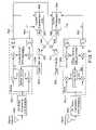
- FIG. 6is a simplified block diagram depicting an implementation of the methodology and apparatus of FIG. 5 ; however, in this instance, two or more slave systems are depicted rather than one.
- the master track loop 700supplies its in-phase data, denoted in the figure by reference numeral 703 to its own CD and to the CDs of slave tracking loop 701 and slave tracking loop 702 .
- Any number of slave track loopsmay be augmented by applying the in-phase term from a single master to each of the slave carrier discriminators. All slaves will thus maintain a 1 ⁇ 2 cycle alignment with the master.
- the differential carrier phase between master and slave or, for that matter any slave pair,will be free of 1 ⁇ 2 cycle ambiguities.
- the tracking loopspreferably need to react similarly and sharing of data between track loops is beneficial.
- Track loops receiving data from each antennashould react nearly identically to track the common carrier phase accelerations.
- carrier phase tracking errorsare summed (or averaged) and supplied to a responsive, high-bandwidth track loop filter that is shared among track loops.
- a lower bandwidth filter that is independent for each track loopis utilized to track the slower but non-common dynamics using the individual phase errors of each system.
- a shared high-bandwidth track loopis employed to dominate the high frequency and noise response.
- the noise induced into the individual carrier phase measurementswill be similar and will cancel in the carrier phase differences that are formed as part of the attitude solution. This, advantageously, results in smoother differential carrier phase observations and ultimately attitude angles that are smoother as well.
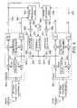
- FIG. 7shows an exemplary embodiment of a multiple track loop receiver system utilizing not only a shared in-phase component, but shared carrier discriminator outputs as well.
- a master track signal processor 801 and a slave track signal processor 851receive carrier data from antennas 800 and 850 , respectively.
- the in-phase data 802 for the master tracking loop 801is delivered to both master and slave carrier discriminators 804 and 854 respectively, so that 1 ⁇ 2 cycle phase tracking alignment can be realized.
- Master carrier discriminator 804computes a phase error 805 and slave carrier discriminator 854 computes a phase error 855 .
- Each phase erroris proportional to the difference of the respective NCO generated phase and the carrier phase of the received signal.
- phase tracking errors 805 and 855 of the master and slaveare each coupled to both track loops.
- Phase error 805is fed to a summer 807 where it is added to phase error 855 that has been multiplied by a scale factor ⁇ using amplifier 856 .
- phase error 855is fed to a summer 857 where it is added to phase error 805 that has also been multiplied by ⁇ using amplifier 806 .
- the value ⁇ of amplifiers 806 and 856is identical in this embodiment, however, other values may be employed.
- the summed signal produced by summer 807is fed to the track filter 808 for the master tracking loop 801 , which is either a proportional plus integral filter or some other track filter that results in a stable feedback control.
- the track filter 808then delivers the NCO step 809 to the carrier NCO for the master tracking loop 801 .
- the summed signal produced by summer 857is fed to the track filter 858 for the slave tracking loop 851 , again, which is either a proportional plus integral filter or some other track filter that results in a stable feedback control.
- the track filter 858then delivers the NCO step 859 to the carrier NCO for the slave tracking loop 851 .
- FIG. 7depicts an exemplary embodiment of information sharing tracking loops that realizes, for each track-loop, a common high-bandwidth response and an independent low-bandwidth response.
- the value of ⁇is selected to be preferably less than one, but somewhat near to one. The closer alpha is to one, the less independent the track loops become. If ⁇ is exactly one, both track loops are supplied exactly the same data and therefore generate the same NCO command. In practice, antennas are typically in separate locations or move separately and therefore require slightly different NCO commands to properly track, thus values other than one are desirable.
- FIG. 8a block diagram is depicted of yet another exemplary embodiment exhibiting a more flexible configuration for implementing a common high-bandwidth response and an independent low-bandwidth response.
- a common high-bandwidth track loop filter 922is completely independent of two individually-steered, low-bandwidth filters 907 and 957 for the master tracking loop 900 and slave tracking loop 950 , respectively.
- tracking loop parameterssuch as proportional plus integral gains, may be adjusted independently to give both desired low-bandwidth and desired high-bandwidth responses. It will be appreciated that up to and including the carrier discriminators 904 and 954 , the track loops are substantially identical to those shown in FIG. 7 .
- phase tracking error 905is proportional to the difference in phase between the phase of the NCO 910 and the carrier phase arriving at antenna for the master tracking loop 900 .
- phase tracking error 955is proportional to the difference in phase between the phase of the NCO 960 and the carrier phase arriving at antenna for the slave tracking loop 950 .
- Track errors 905 and 955are summed at 920 ; the sum 921 is then delivered to the common track filter 922 .
- the common track loop filterhas its own set of parameters, such as proportional and integral gains.
- the output 923 of the common track loopis fed to the master NCO through summer 924 and to the slave NCO through summer 925 .
- the master's independent track loop filter 907utilizes only the master's track error 905 which is scaled through the amplifier 906 having a gain of ⁇ .
- the slave's independent track loop filter 957utilizes only the slave's track error 955 which is scaled through amplifier 956 of gain ⁇ .
- both track loops 907 and 957employ identical filters (although it will be appreciated that they need not), which are typically adjusted to yield lower bandwidth response than the common track filter 922 .
- the output 908 of the master's independent track filteris added to the common track filter output 923 and fed to the master's carrier NCO 910 .
- the output 958 of the slave independent track filteris added to the common track filter output 923 and fed to the slave 's carrier NCO 960 . Ultimate track loop response and degree of track loop independence is readily configurable by the designer.
- FIG. 7 and FIG. 8are just two illustrative configurations for realizing carrier track loops that have a common mode noise-induced phase error and common 1 ⁇ 2 cycle ambiguity, these commonalities canceling when differencing the phase from each NCO.
- One skilled in the artmay readily envision numerous variations and other realizations that would lead to and achieve similar results.
- this disclosurethus far has made reference to the application of this invention with respect to an illustration as an attitude or heading system, it may readily be applied to a more general class of GNSS devices and applications.
- One such applicationwould be a local survey system where one antenna is used as a reference and another is used to survey a location relative to a reference. Both antennas of which are connected to a common receiver that maintains tracking of signals arriving at each antenna.
- the two systemsneed only ensure that the tracking loops of two or more receivers can share data at a rate consistent with the track loops update rate and that antennas that receive the carrier signals be sufficiently close together so that data bit transitions occur at roughly the same time (e.g., within 10%) relative to the in-phase and quadrature phase accumulation window start/stop times. It will be further appreciated that these constraints may be relaxed if the master and slave tracking loops run in non-real time (perhaps in post processing software) where methods can be applied to share and align data without concern for real-time processing constraints.
- pipeline delayscan be introduced into a real-time system's data flow so that even when antennas are spaced widely (or signals arrive at different times for other reasons such as hardware or filtering delays), data bit transitions can be aligned between track loops.
- different bit arrival timesare not an issue, for even if data accumulations occur over windows as small as one millisecond, antenna spacing would have to exceed 30 kilometers before signal travel delays induced a 10% misalignment of the accumulation windows.
- the system and methodology described in the numerous embodiments hereinbeforeprovide a system and method of positioning or attitude determination that is effective and advantageously exploits Global Navigation Satellite System (GNSS) signals to infer differential path length of carrier signals arriving at two or more antennas.
- GNSSGlobal Navigation Satellite System
- the described embodimentsprovide an improved tracking loop for carrier phase tracking.
- the disclosed inventionmay be embodied in the form of computer-implemented processes and apparatuses for practicing those processes.
- the present inventioncan also be embodied in the form of computer program code containing instructions embodied in tangible media, such as floppy diskettes, CD-ROMs, hard drives, or any other computer-readable storage medium, wherein when the computer program code is loaded into and executed by a computer, the computer becomes an apparatus for practicing the invention.
- the present inventioncan also be embodied in the form of computer program code, for example, whether stored in a storage medium, loaded into and/or executed by a computer, or as data signal transmitted, whether a modulated carrier wave or not, over some transmission medium, such as over electrical wiring or cabling, through fiber optics, or via electromagnetic radiation, wherein, when the computer program code is loaded into and executed by a computer, the computer becomes an apparatus for practicing the invention.
- the computer program code segmentsconfigure the microprocessor to create specific logic circuits.
Landscapes
- Engineering & Computer Science (AREA)
- Radar, Positioning & Navigation (AREA)
- Remote Sensing (AREA)
- Computer Networks & Wireless Communication (AREA)
- Physics & Mathematics (AREA)
- General Physics & Mathematics (AREA)
- Position Fixing By Use Of Radio Waves (AREA)
Abstract
Description
CD=Qpsign(Ip)
where the sign( ) function takes the arithmetic sign (+1 or −1) of the enclosed argument which, in this case, is the sign of Ip. Another common discriminator function is
CD=Tan−1(Qp/Ip)
phase error=(carrier phase of received signal)−(phase of NCO).
CD=Tan−1(Qp/Ip).
CD=Qpsign(Idata)
where Idatais defined as having the known sign of the modulating data. Since Idatais not a function of phase track error, the CD only depends on the term Qpand is thus similar to a conventional PLL discriminator in this respect. For example, the PLL discriminator shown in
CD=Qpsign(−Idata)
CDmaster=Qmastersign(Imaster)
CDslave=Qslavesign(Imaster)
Where we have adopted the following notation:
- Imasteris the in-phase data from the master track loop;
- Qmasteris the quadrature-phase data from the master track loop;
- Islaveis the in-phase data from the slave track loop; and
- Qslaveis the quadrature-phase data from the slave track loop.
CDslave=Qslavesign(Imaster)
CDslave=Qslavesign(Idata).
Claims (20)
Priority Applications (1)
| Application Number | Priority Date | Filing Date | Title |
|---|---|---|---|
| US11/253,871US7388539B2 (en) | 2005-10-19 | 2005-10-19 | Carrier track loop for GNSS derived attitude |
Applications Claiming Priority (1)
| Application Number | Priority Date | Filing Date | Title |
|---|---|---|---|
| US11/253,871US7388539B2 (en) | 2005-10-19 | 2005-10-19 | Carrier track loop for GNSS derived attitude |
Publications (2)
| Publication Number | Publication Date |
|---|---|
| US20070085738A1 US20070085738A1 (en) | 2007-04-19 |
| US7388539B2true US7388539B2 (en) | 2008-06-17 |
Family
ID=37947687
Family Applications (1)
| Application Number | Title | Priority Date | Filing Date |
|---|---|---|---|
| US11/253,871Active2026-06-21US7388539B2 (en) | 2005-10-19 | 2005-10-19 | Carrier track loop for GNSS derived attitude |
Country Status (1)
| Country | Link |
|---|---|
| US (1) | US7388539B2 (en) |
Cited By (38)
| Publication number | Priority date | Publication date | Assignee | Title |
|---|---|---|---|---|
| US20080147282A1 (en)* | 2006-12-15 | 2008-06-19 | Georg Kormann | Tracking system configured to determine a parameter for use in guiding an implement attached to a work machine |
| US20080269988A1 (en)* | 2003-03-20 | 2008-10-30 | Feller Walter J | Combined gnss gyroscope control system and method |
| US20090121932A1 (en)* | 2003-03-20 | 2009-05-14 | Whitehead Michael L | Multi-antenna gnss positioning method and system |
| US20090284210A1 (en)* | 2008-05-15 | 2009-11-19 | Honeywell International Inc., Patent Services | Adaptive servo control system and method |
| US20090322600A1 (en)* | 2004-03-19 | 2009-12-31 | Whitehead Michael L | Method and system using gnss phase measurements for relative positioning |
| US7835832B2 (en) | 2007-01-05 | 2010-11-16 | Hemisphere Gps Llc | Vehicle control system |
| US7885745B2 (en) | 2002-12-11 | 2011-02-08 | Hemisphere Gps Llc | GNSS control system and method |
| US7948769B2 (en) | 2007-09-27 | 2011-05-24 | Hemisphere Gps Llc | Tightly-coupled PCB GNSS circuit and manufacturing method |
| US8000381B2 (en) | 2007-02-27 | 2011-08-16 | Hemisphere Gps Llc | Unbiased code phase discriminator |
| US8018376B2 (en) | 2008-04-08 | 2011-09-13 | Hemisphere Gps Llc | GNSS-based mobile communication system and method |
| US8085196B2 (en) | 2009-03-11 | 2011-12-27 | Hemisphere Gps Llc | Removing biases in dual frequency GNSS receivers using SBAS |
| US8138970B2 (en) | 2003-03-20 | 2012-03-20 | Hemisphere Gps Llc | GNSS-based tracking of fixed or slow-moving structures |
| US8140223B2 (en) | 2003-03-20 | 2012-03-20 | Hemisphere Gps Llc | Multiple-antenna GNSS control system and method |
| US8174437B2 (en) | 2009-07-29 | 2012-05-08 | Hemisphere Gps Llc | System and method for augmenting DGNSS with internally-generated differential correction |
| US8190337B2 (en) | 2003-03-20 | 2012-05-29 | Hemisphere GPS, LLC | Satellite based vehicle guidance control in straight and contour modes |
| US8217833B2 (en) | 2008-12-11 | 2012-07-10 | Hemisphere Gps Llc | GNSS superband ASIC with simultaneous multi-frequency down conversion |
| US8248300B2 (en) | 2010-06-02 | 2012-08-21 | Honeywell International Inc. | System and method of compensating for micro-jump events |
| US8311696B2 (en) | 2009-07-17 | 2012-11-13 | Hemisphere Gps Llc | Optical tracking vehicle control system and method |
| US8334804B2 (en) | 2009-09-04 | 2012-12-18 | Hemisphere Gps Llc | Multi-frequency GNSS receiver baseband DSP |
| US20130041549A1 (en)* | 2007-01-05 | 2013-02-14 | David R. Reeve | Optical tracking vehicle control system and method |
| US8386129B2 (en) | 2009-01-17 | 2013-02-26 | Hemipshere GPS, LLC | Raster-based contour swathing for guidance and variable-rate chemical application |
| US8401704B2 (en) | 2009-07-22 | 2013-03-19 | Hemisphere GPS, LLC | GNSS control system and method for irrigation and related applications |
| US8456356B2 (en) | 2007-10-08 | 2013-06-04 | Hemisphere Gnss Inc. | GNSS receiver and external storage device system and GNSS data processing method |
| US8548649B2 (en) | 2009-10-19 | 2013-10-01 | Agjunction Llc | GNSS optimized aircraft control system and method |
| US8583326B2 (en) | 2010-02-09 | 2013-11-12 | Agjunction Llc | GNSS contour guidance path selection |
| US8583315B2 (en) | 2004-03-19 | 2013-11-12 | Agjunction Llc | Multi-antenna GNSS control system and method |
| US8594879B2 (en) | 2003-03-20 | 2013-11-26 | Agjunction Llc | GNSS guidance and machine control |
| US8649930B2 (en) | 2009-09-17 | 2014-02-11 | Agjunction Llc | GNSS integrated multi-sensor control system and method |
| US9002566B2 (en) | 2008-02-10 | 2015-04-07 | AgJunction, LLC | Visual, GNSS and gyro autosteering control |
| US9476989B2 (en) | 2014-04-16 | 2016-10-25 | Honeywell International Inc. | Vector tracking loop operability through oscillator micro-jump event |
| US9557418B2 (en) | 2014-04-15 | 2017-01-31 | Honeywell International Inc. | Ground-based system and method to extend the detection of excessive delay gradients using parity corrections |
| US9599716B2 (en) | 2014-04-15 | 2017-03-21 | Honeywell International Inc. | Ground-based system and method to extend the detection of excessive delay gradients using dual processing |
| CN106526630A (en)* | 2015-09-11 | 2017-03-22 | 清华大学 | Method and device for eliminating half-cycle ambiguity |
| US20170261618A1 (en)* | 2015-10-06 | 2017-09-14 | Topcon Positioning Systems, Inc. | Navigation receiver with an adaptive system for tracking carrier phases received from a constellation of navigation satellites |
| US9880562B2 (en) | 2003-03-20 | 2018-01-30 | Agjunction Llc | GNSS and optical guidance and machine control |
| USRE47101E1 (en) | 2003-03-20 | 2018-10-30 | Agjunction Llc | Control for dispensing material from vehicle |
| USRE48527E1 (en)* | 2007-01-05 | 2021-04-20 | Agjunction Llc | Optical tracking vehicle control system and method |
| US11148659B2 (en)* | 2017-06-08 | 2021-10-19 | Caterpillar Sarl | Stability of work machines |
Families Citing this family (6)
| Publication number | Priority date | Publication date | Assignee | Title |
|---|---|---|---|---|
| JP3806425B2 (en)* | 2003-12-01 | 2006-08-09 | マゼランシステムズジャパン株式会社 | Satellite positioning method and satellite positioning system |
| US7528769B2 (en)* | 2006-11-27 | 2009-05-05 | Nokia Corporation | Enhancing the usability of carrier phase measurements |
| CN101435866B (en)* | 2008-11-26 | 2012-04-04 | 苏州莱迪斯特电子有限公司 | Carrier wave tracking system and method of GPS coarse / capturing code signal |
| US10304342B2 (en) | 2016-11-08 | 2019-05-28 | Ge Aviation Systems Llc | Ground-based data acquisition system |
| CN106707307B (en)* | 2016-12-21 | 2019-06-18 | 湖南北云科技有限公司 | A kind of satellite navigation half cycle transition detection method and device |
| US12166623B2 (en)* | 2020-10-21 | 2024-12-10 | The Regents Of The University Of Colorado, A Body Corporate | Filtering method for carrier phase measurements from open-loop tracking |
Citations (133)
| Publication number | Priority date | Publication date | Assignee | Title |
|---|---|---|---|---|
| US3727710A (en) | 1971-05-13 | 1973-04-17 | Gen Motors Corp | Steer control for a track-laying vehicle |
| US3899028A (en) | 1972-03-30 | 1975-08-12 | Systron Donner Corp | Angular position sensing and control system, apparatus and method |
| US4132272A (en) | 1977-06-30 | 1979-01-02 | International Harvester Company | Tractor hitch position control system |
| US4180133A (en) | 1978-01-12 | 1979-12-25 | Iowa State University Research Foundation, Inc. | Guidance system for towed vehicles |
| US4453614A (en) | 1982-03-19 | 1984-06-12 | Deere & Company | Steering arrangement for an off-highway articulated vehicle |
| US4637474A (en) | 1974-11-05 | 1987-01-20 | Leonard Willie B | Tractor and towed implement with elevation control system for implement including pressure responsive valve actuator |
| US4802545A (en) | 1986-10-15 | 1989-02-07 | J. I. Case Company | Steering control system for articulated vehicle |
| US4858132A (en) | 1987-09-11 | 1989-08-15 | Ndc Technologies, Inc. | Optical navigation system for an automatic guided vehicle, and method |
| US4918607A (en) | 1988-09-09 | 1990-04-17 | Caterpillar Industrial Inc. | Vehicle guidance system |
| US5031704A (en) | 1988-05-10 | 1991-07-16 | Fleischer Manufacturing, Inc. | Guidance control apparatus for agricultural implement |
| US5134407A (en) | 1991-04-10 | 1992-07-28 | Ashtech Telesis, Inc. | Global positioning system receiver digital processing technique |
| US5152347A (en) | 1991-04-05 | 1992-10-06 | Deere & Company | Interface system for a towed implement |
| US5156219A (en) | 1990-06-04 | 1992-10-20 | A.I.L., Inc. | Positioning apparatus for drawn implement |
| US5185610A (en) | 1990-08-20 | 1993-02-09 | Texas Instruments Incorporated | GPS system and method for deriving pointing or attitude from a single GPS receiver |
| US5202829A (en) | 1991-06-10 | 1993-04-13 | Trimble Navigation Limited | Exploration system and method for high-accuracy and high-confidence level relative position and velocity determinations |
| US5207239A (en) | 1991-07-30 | 1993-05-04 | Aura Systems, Inc. | Variable gain servo assist |
| US5255756A (en) | 1992-04-22 | 1993-10-26 | Progressive Farm Products, Inc. | Caddy with guidance system for agricultural implements |
| US5268695A (en)* | 1992-10-06 | 1993-12-07 | Trimble Navigation Limited | Differential phase measurement through antenna multiplexing |
| US5296861A (en) | 1992-11-13 | 1994-03-22 | Trimble Navigation Limited | Method and apparatus for maximum likelihood estimation direct integer search in differential carrier phase attitude determination systems |
| US5343209A (en) | 1992-05-07 | 1994-08-30 | Sennott James W | Navigation receiver with coupled signal-tracking channels |
| US5369589A (en) | 1993-09-15 | 1994-11-29 | Trimble Navigation Limited | Plural information display for navigation |
| US5375059A (en) | 1990-02-05 | 1994-12-20 | Caterpillar Inc. | Vehicle position determination system and method |
| US5416712A (en) | 1993-05-28 | 1995-05-16 | Trimble Navigation Limited | Position and velocity estimation system for adaptive weighting of GPS and dead-reckoning information |
| US5476147A (en) | 1993-03-19 | 1995-12-19 | Fixemer; Richard A. | Guidance system for an agricultural implement |
| US5491636A (en) | 1994-04-19 | 1996-02-13 | Glen E. Robertson | Anchorless boat positioning employing global positioning system |
| US5511623A (en) | 1994-09-12 | 1996-04-30 | Orthman Manufacturing, Inc. | Quick hitch guidance device |
| US5534875A (en) | 1993-06-18 | 1996-07-09 | Adroit Systems, Inc. | Attitude determining system for use with global positioning system |
| US5543804A (en) | 1994-09-13 | 1996-08-06 | Litton Systems, Inc. | Navagation apparatus with improved attitude determination |
| US5546093A (en) | 1994-01-04 | 1996-08-13 | Caterpillar Inc. | System and method for providing navigation signals to an earthmoving or construction machine |
| US5548293A (en) | 1993-03-24 | 1996-08-20 | Leland Stanford Junior University | System and method for generating attitude determinations using GPS |
| US5561432A (en) | 1995-05-12 | 1996-10-01 | Trimble Navigation | Out of plane antenna vector system and method |
| US5564632A (en) | 1994-12-27 | 1996-10-15 | Combustion Engineering, Inc. | Secondary air nozzle and starting burner furnace apparatus |
| US5592382A (en) | 1995-03-10 | 1997-01-07 | Rockwell International Corporation | Directional steering and navigation indicator |
| US5610845A (en) | 1994-08-30 | 1997-03-11 | United Technologies Corporation | Multi-parameter air data sensing technique |
| US5612883A (en) | 1990-02-05 | 1997-03-18 | Caterpillar Inc. | System and method for detecting obstacles in the path of a vehicle |
| US5617317A (en) | 1995-01-24 | 1997-04-01 | Honeywell Inc. | True north heading estimator utilizing GPS output information and inertial sensor system output information |
| US5644139A (en) | 1995-03-02 | 1997-07-01 | Allen; Ross R. | Navigation technique for detecting movement of navigation sensors relative to an object |
| US5691974A (en)* | 1995-01-04 | 1997-11-25 | Qualcomm Incorporated | Method and apparatus for using full spectrum transmitted power in a spread spectrum communication system for tracking individual recipient phase, time and energy |
| US5717593A (en) | 1995-09-01 | 1998-02-10 | Gvili; Michael E. | Lane guidance system |
| US5725230A (en) | 1996-06-17 | 1998-03-10 | Walkup; Joseph L. | Self steering tandem hitch |
| US5757316A (en) | 1997-02-01 | 1998-05-26 | Litton Systems, Inc. | Attitude determination utilizing an inertial measurement unit and a plurality of satellite transmitters |
| US5765123A (en) | 1993-08-07 | 1998-06-09 | Aisin Aw Co., Ltd. | Navigation system |
| US5777578A (en) | 1997-02-10 | 1998-07-07 | National Science Council | Global positioning system (GPS) Compass |
| WO1998036288A1 (en) | 1997-02-14 | 1998-08-20 | Kelvin Korver | A navigation/guidance system for a land-based vehicle |
| US5810095A (en) | 1996-07-25 | 1998-09-22 | Case Corporation | System for controlling the position of an implement attached to a work vehicle |
| US5862501A (en) | 1995-08-18 | 1999-01-19 | Trimble Navigation Limited | Guidance control system for movable machinery |
| US5875408A (en) | 1995-07-17 | 1999-02-23 | Imra America, Inc. | Automated vehicle guidance system and method for automatically guiding a vehicle |
| US5918558A (en) | 1997-12-01 | 1999-07-06 | Case Corporation | Dual-pump, flow-isolated hydraulic circuit for an agricultural tractor |
| US5923270A (en) | 1994-05-13 | 1999-07-13 | Modulaire Oy | Automatic steering system for an unmanned vehicle |
| US5928309A (en) | 1996-02-05 | 1999-07-27 | Korver; Kelvin | Navigation/guidance system for a land-based vehicle |
| US5933110A (en) | 1998-07-13 | 1999-08-03 | Arinc, Inc. | Vessel attitude determination system and method |
| US5935183A (en) | 1996-05-20 | 1999-08-10 | Caterpillar Inc. | Method and system for determining the relationship between a laser plane and an external coordinate system |
| US5940026A (en) | 1997-07-21 | 1999-08-17 | Rockwell Science Center, Inc. | Azimuth determination for GPS/INS systems via GPS null steering antenna |
| US5943008A (en) | 1997-09-23 | 1999-08-24 | Rockwell Science Center, Inc. | Single global positioning system receiver capable of attitude determination |
| US5945917A (en) | 1997-12-18 | 1999-08-31 | Rockwell International | Swathing guidance display |
| US5969670A (en) | 1998-01-22 | 1999-10-19 | Trimble Navigation Limited | Inexpensive monitoring technique for achieving high level integrity monitoring for differential GPS |
| US5987383A (en) | 1997-04-28 | 1999-11-16 | Trimble Navigation | Form line following guidance system |
| US6014608A (en) | 1996-11-04 | 2000-01-11 | Samsung Electronics Co., Ltd. | Navigator apparatus informing or peripheral situation of the vehicle and method for controlling the same |
| US6052647A (en) | 1997-06-20 | 2000-04-18 | Stanford University | Method and system for automatic control of vehicles based on carrier phase differential GPS |
| US6057800A (en) | 1996-06-28 | 2000-05-02 | State University Of New York | RDOP surface for GPS relative positioning |
| WO2000024239A1 (en) | 1998-10-27 | 2000-05-04 | Agsystems Pty. Ltd. | Vehicle positioning apparatus and method |
| US6061390A (en) | 1994-09-02 | 2000-05-09 | California Institute Of Technology | P-code enhanced method for processing encrypted GPS signals without knowledge of the encryption code |
| US6062317A (en) | 1999-09-03 | 2000-05-16 | Caterpillar Inc. | Method and apparatus for controlling the direction of travel of an earthworking machine |
| US6069583A (en)* | 1996-05-09 | 2000-05-30 | Agence Spatiale Europeene | Receiver for a navigation system, in particular a satellite navigation system |
| US6076612A (en) | 1999-08-31 | 2000-06-20 | Case Corporation | Transition from position to draft mode controlled by hitch position command and feedback |
| US6122595A (en) | 1996-05-20 | 2000-09-19 | Harris Corporation | Hybrid GPS/inertially aided platform stabilization system |
| US6150978A (en) | 1997-12-05 | 2000-11-21 | Trimble Navigation Limited | GPS receiver having fast resolution of carrier phase ambiguity |
| US6191733B1 (en) | 1999-06-01 | 2001-02-20 | Modular Mining Systems, Inc. | Two-antenna positioning system for surface-mine equipment |
| US6191730B1 (en)* | 1997-12-15 | 2001-02-20 | Trimble Navigation Limited | Two-channel fast-sequencing high-dynamics GPS navigation receiver |
| US6199000B1 (en) | 1998-07-15 | 2001-03-06 | Trimble Navigation Limited | Methods and apparatus for precision agriculture operations utilizing real time kinematic global positioning system systems |
| US6198992B1 (en) | 1997-10-10 | 2001-03-06 | Trimble Navigation Limited | Override for guidance control system |
| US6205401B1 (en) | 1995-09-19 | 2001-03-20 | Litef Gmbh | Navigation system for a vehicle, especially a land craft |
| US6229479B1 (en) | 1997-04-25 | 2001-05-08 | Magellan Corporation | Relative position measuring techniques using both GPS and GLONASS carrier phase measurements |
| US6233511B1 (en) | 1997-11-26 | 2001-05-15 | Case Corporation | Electronic control for a two-axis work implement |
| US6236916B1 (en) | 1999-03-29 | 2001-05-22 | Caterpillar Inc. | Autoguidance system and method for an agricultural machine |
| US6236924B1 (en) | 1999-06-21 | 2001-05-22 | Caterpillar Inc. | System and method for planning the operations of an agricultural machine in a field |
| US6253160B1 (en) | 1999-01-15 | 2001-06-26 | Trimble Navigation Ltd. | Method and apparatus for calibrating a tool positioning mechanism on a mobile machine |
| US6256583B1 (en) | 1998-09-16 | 2001-07-03 | Rockwell Collins, Inc. | GPS attitude determination system and method using optimal search space identification for integer cycle ambiguity resolution |
| US6259398B1 (en) | 2000-05-19 | 2001-07-10 | Sri International | Multi-valued variable ambiguity resolution for satellite navigation signal carrier wave path length determination |
| US6285320B1 (en) | 1999-09-03 | 2001-09-04 | Sikorsky Aircraft Corporation | Apparatus and method for mapping surfaces of an object |
| US6292132B1 (en) | 1999-08-13 | 2001-09-18 | Daimlerchrysler Ag | System and method for improved accuracy in locating and maintaining positions using GPS |
| US6314348B1 (en) | 1998-02-11 | 2001-11-06 | Trimble Navigation Limited | Correction control for guidance control system |
| US6313789B1 (en) | 1998-06-10 | 2001-11-06 | Topcon Positioning Systems, Inc. | Joint tracking of the carrier phases of the signals received from different satellites |
| US6313788B1 (en) | 1998-08-14 | 2001-11-06 | Seagull Technology, Inc. | Method and apparatus for reliable inter-antenna baseline determination |
| US6325684B1 (en) | 1999-06-11 | 2001-12-04 | Johnson Outdoors, Inc., | Trolling motor steering control |
| US6345231B2 (en) | 1998-07-10 | 2002-02-05 | Claas Selbstfahrende Erntemaschinen Gmbh | Method and apparatus for position determining |
| US20020029110A1 (en) | 2000-06-01 | 2002-03-07 | Masaru Fukuda | System for determining the heading and/or attitude of a body |
| US20020038171A1 (en) | 2000-09-28 | 2002-03-28 | Nissan Motor Co., Ltd. | Apparatus for and method of steering vehicle |
| US6377889B1 (en) | 2000-10-13 | 2002-04-23 | Trimble Navigation Limited | Non-linear method of guiding to arbitrary curves with adaptive feedback |
| US6389345B2 (en) | 1999-06-29 | 2002-05-14 | Caterpillar Inc. | Method and apparatus for determining a cross slope of a surface |
| US6397147B1 (en) | 2000-06-06 | 2002-05-28 | Csi Wireless Inc. | Relative GPS positioning using a single GPS receiver with internally generated differential correction terms |
| US20020072850A1 (en) | 2000-12-08 | 2002-06-13 | Mcclure John A. | GPS derived swathing guidance system |
| US6421003B1 (en) | 2000-05-19 | 2002-07-16 | Sri International | Attitude determination using multiple baselines in a navigational positioning system |
| US6431576B1 (en) | 1999-04-28 | 2002-08-13 | Deere & Company | System for steering towed implement in response to, or independently of, steering of towing vehicle |
| US6434462B1 (en) | 2001-06-28 | 2002-08-13 | Deere & Company | GPS control of a tractor-towed implement |
| US6445990B1 (en) | 2001-03-19 | 2002-09-03 | Caterpillar Inc. | Method and apparatus for controlling straight line travel of a tracked machine |
| US6445983B1 (en) | 2000-07-07 | 2002-09-03 | Case Corporation | Sensor-fusion navigator for automated guidance of off-road vehicles |
| US6466871B1 (en) | 1999-10-03 | 2002-10-15 | Azimuth Technologies | Method for calibrating and verifying the attitude of a compass |
| US6469663B1 (en) | 2000-03-21 | 2002-10-22 | Csi Wireless Inc. | Method and system for GPS and WAAS carrier phase measurements for relative positioning |
| US20020165648A1 (en) | 2001-05-07 | 2002-11-07 | Zeitler David W. | AGV position and heading controller |
| US20020165669A1 (en) | 2001-02-28 | 2002-11-07 | Enpoint, L.L.C. | Attitude measurement using a single GPS receiver with two closely-spaced antennas |
| US20020169553A1 (en) | 2001-05-11 | 2002-11-14 | Perlmutter Michael S. | Method and system for calibrating an IG/GP navigational system |
| US20020175858A1 (en) | 2001-03-28 | 2002-11-28 | Communications Res. Lab., Ind. Admin. Inst. (90%) | Method for acquiring azimuth information |
| US6501422B1 (en) | 1998-08-19 | 2002-12-31 | Trimble Navigation, Ltd. | Precise parallel swathing guidance via satellite navigation and tilt measurement |
| US20030009282A1 (en) | 2001-06-29 | 2003-01-09 | The Regents Of The University Of California | Method and apparatus for ultra precise gps-based mapping of seeds or vegetation during planting |
| US6515619B1 (en) | 1998-07-30 | 2003-02-04 | Mckay, Jr. Nicholas D. | Object location system |
| WO2003019430A1 (en) | 2001-08-29 | 2003-03-06 | Beeline Technologies Pty Ltd | Vehicle guidance software, method and system |
| US6542077B2 (en) | 1993-06-08 | 2003-04-01 | Raymond Anthony Joao | Monitoring apparatus for a vehicle and/or a premises |
| US6553311B2 (en) | 2000-12-08 | 2003-04-22 | Trimble Navigation Limited | Navigational off- line and off-heading indication system and method |
| US6556942B1 (en)* | 2000-09-29 | 2003-04-29 | Ut-Battelle, Llc | Short range spread-spectrum radiolocation system and method |
| US6577952B2 (en) | 2001-01-08 | 2003-06-10 | Motorola, Inc. | Position and heading error-correction method and apparatus for vehicle navigation systems |
| US6587761B2 (en) | 2001-10-23 | 2003-07-01 | The Aerospace Corporation | Unambiguous integer cycle attitude determination method |
| US6611228B2 (en) | 2000-07-24 | 2003-08-26 | Furuno Electric Company, Limited | Carrier phase-based relative positioning apparatus |
| US6631916B1 (en) | 2000-07-28 | 2003-10-14 | Merle E. Miller | Guidance system for pull-type equipment |
| US6643576B1 (en) | 2000-11-15 | 2003-11-04 | Integrinautics Corporation | Rapid adjustment of trajectories for land vehicles |
| US6646603B2 (en) | 2000-06-16 | 2003-11-11 | Koninklijke Philips Electronics, N.V. | Method of providing an estimate of a location |
| US6657585B1 (en) | 2002-05-21 | 2003-12-02 | The United States Of America As Represented By The Secretary Of The Navy | System for generating GPS position of underwater vehicle |
| US6671587B2 (en) | 2002-02-05 | 2003-12-30 | Ford Motor Company | Vehicle dynamics measuring apparatus and method using multiple GPS antennas |
| US6688403B2 (en) | 2001-03-22 | 2004-02-10 | Deere & Company | Control system for a vehicle/implement hitch |
| US6711501B2 (en) | 2000-12-08 | 2004-03-23 | Satloc, Llc | Vehicle navigation system and method for swathing applications |
| US6775802B2 (en) | 2000-08-08 | 2004-08-10 | Qualcomm Incorporated | Method, apparatus, and system for signal prediction |
| US6792380B2 (en) | 2002-02-12 | 2004-09-14 | Furuno Electric Company Limited | Attitude angle detecting apparatus |
| US20040186644A1 (en) | 2003-03-20 | 2004-09-23 | Mcclure John A. | Satellite based vehicle guidance control in straight and contour modes |
| US20040210357A1 (en) | 2003-04-17 | 2004-10-21 | Mckay Mark D. | Auto-steering apparatus and method |
| US20040212533A1 (en) | 2003-04-23 | 2004-10-28 | Whitehead Michael L. | Method and system for satellite based phase measurements for relative positioning of fixed or slow moving points in close proximity |
| US6865465B2 (en) | 2002-05-06 | 2005-03-08 | Csi Wireless, Inc. | Method and system for implement steering for agricultural vehicles |
| US20050116859A1 (en)* | 2003-04-23 | 2005-06-02 | Miller Steven R. | Method and system for synchronizing multiple tracking devices for a geo-location system |
| US6922635B2 (en) | 2002-08-13 | 2005-07-26 | Drs Communications Company, Llc | Method and system for determining absolute positions of mobile communications devices using remotely generated positioning information |
| WO2005119386A1 (en) | 2004-05-17 | 2005-12-15 | Csi Wireless Inc. | Satellite based vehicle guidance control in straight and contour modes |
| US7027918B2 (en) | 2003-04-07 | 2006-04-11 | Novariant, Inc. | Satellite navigation system using multiple antennas |
| US7031725B2 (en) | 2002-08-13 | 2006-04-18 | Drs Communications Company, Llc | Method and system for determining relative positions of networked mobile communication devices |
| US20060251173A1 (en)* | 2005-05-06 | 2006-11-09 | Hansheng Wang | Efficient and flexible GPS receiver baseband architecture |
| US7162348B2 (en) | 2002-12-11 | 2007-01-09 | Hemisphere Gps Llc | Articulated equipment position control system and method |
- 2005
- 2005-10-19USUS11/253,871patent/US7388539B2/enactiveActive
Patent Citations (146)
| Publication number | Priority date | Publication date | Assignee | Title |
|---|---|---|---|---|
| US3727710A (en) | 1971-05-13 | 1973-04-17 | Gen Motors Corp | Steer control for a track-laying vehicle |
| US3899028A (en) | 1972-03-30 | 1975-08-12 | Systron Donner Corp | Angular position sensing and control system, apparatus and method |
| US4637474A (en) | 1974-11-05 | 1987-01-20 | Leonard Willie B | Tractor and towed implement with elevation control system for implement including pressure responsive valve actuator |
| US4132272A (en) | 1977-06-30 | 1979-01-02 | International Harvester Company | Tractor hitch position control system |
| US4180133A (en) | 1978-01-12 | 1979-12-25 | Iowa State University Research Foundation, Inc. | Guidance system for towed vehicles |
| US4453614A (en) | 1982-03-19 | 1984-06-12 | Deere & Company | Steering arrangement for an off-highway articulated vehicle |
| US4802545A (en) | 1986-10-15 | 1989-02-07 | J. I. Case Company | Steering control system for articulated vehicle |
| US4858132A (en) | 1987-09-11 | 1989-08-15 | Ndc Technologies, Inc. | Optical navigation system for an automatic guided vehicle, and method |
| US5031704A (en) | 1988-05-10 | 1991-07-16 | Fleischer Manufacturing, Inc. | Guidance control apparatus for agricultural implement |
| US4918607A (en) | 1988-09-09 | 1990-04-17 | Caterpillar Industrial Inc. | Vehicle guidance system |
| US5956250A (en) | 1990-02-05 | 1999-09-21 | Caterpillar Inc. | Apparatus and method for autonomous vehicle navigation using absolute data |
| US5838562A (en) | 1990-02-05 | 1998-11-17 | Caterpillar Inc. | System and a method for enabling a vehicle to track a preset path |
| US5615116A (en) | 1990-02-05 | 1997-03-25 | Caterpillar Inc. | Apparatus and method for autonomous vehicle navigation using path data |
| US5684696A (en) | 1990-02-05 | 1997-11-04 | Caterpillar Inc. | System and method for enabling an autonomous vehicle to track a desired path |
| US5390125A (en) | 1990-02-05 | 1995-02-14 | Caterpillar Inc. | Vehicle position determination system and method |
| US5612883A (en) | 1990-02-05 | 1997-03-18 | Caterpillar Inc. | System and method for detecting obstacles in the path of a vehicle |
| US5375059A (en) | 1990-02-05 | 1994-12-20 | Caterpillar Inc. | Vehicle position determination system and method |
| US5156219A (en) | 1990-06-04 | 1992-10-20 | A.I.L., Inc. | Positioning apparatus for drawn implement |
| US5185610A (en) | 1990-08-20 | 1993-02-09 | Texas Instruments Incorporated | GPS system and method for deriving pointing or attitude from a single GPS receiver |
| US5152347A (en) | 1991-04-05 | 1992-10-06 | Deere & Company | Interface system for a towed implement |
| US5134407A (en) | 1991-04-10 | 1992-07-28 | Ashtech Telesis, Inc. | Global positioning system receiver digital processing technique |
| US5202829A (en) | 1991-06-10 | 1993-04-13 | Trimble Navigation Limited | Exploration system and method for high-accuracy and high-confidence level relative position and velocity determinations |
| US5207239A (en) | 1991-07-30 | 1993-05-04 | Aura Systems, Inc. | Variable gain servo assist |
| US5255756A (en) | 1992-04-22 | 1993-10-26 | Progressive Farm Products, Inc. | Caddy with guidance system for agricultural implements |
| US5343209A (en) | 1992-05-07 | 1994-08-30 | Sennott James W | Navigation receiver with coupled signal-tracking channels |
| US5268695A (en)* | 1992-10-06 | 1993-12-07 | Trimble Navigation Limited | Differential phase measurement through antenna multiplexing |
| US5296861A (en) | 1992-11-13 | 1994-03-22 | Trimble Navigation Limited | Method and apparatus for maximum likelihood estimation direct integer search in differential carrier phase attitude determination systems |
| US5476147A (en) | 1993-03-19 | 1995-12-19 | Fixemer; Richard A. | Guidance system for an agricultural implement |
| US5548293A (en) | 1993-03-24 | 1996-08-20 | Leland Stanford Junior University | System and method for generating attitude determinations using GPS |
| US5416712A (en) | 1993-05-28 | 1995-05-16 | Trimble Navigation Limited | Position and velocity estimation system for adaptive weighting of GPS and dead-reckoning information |
| US6542077B2 (en) | 1993-06-08 | 2003-04-01 | Raymond Anthony Joao | Monitoring apparatus for a vehicle and/or a premises |
| US5534875A (en) | 1993-06-18 | 1996-07-09 | Adroit Systems, Inc. | Attitude determining system for use with global positioning system |
| US5765123A (en) | 1993-08-07 | 1998-06-09 | Aisin Aw Co., Ltd. | Navigation system |
| US5369589A (en) | 1993-09-15 | 1994-11-29 | Trimble Navigation Limited | Plural information display for navigation |
| US5546093A (en) | 1994-01-04 | 1996-08-13 | Caterpillar Inc. | System and method for providing navigation signals to an earthmoving or construction machine |
| US5491636A (en) | 1994-04-19 | 1996-02-13 | Glen E. Robertson | Anchorless boat positioning employing global positioning system |
| US5923270A (en) | 1994-05-13 | 1999-07-13 | Modulaire Oy | Automatic steering system for an unmanned vehicle |
| US5610845A (en) | 1994-08-30 | 1997-03-11 | United Technologies Corporation | Multi-parameter air data sensing technique |
| US6061390A (en) | 1994-09-02 | 2000-05-09 | California Institute Of Technology | P-code enhanced method for processing encrypted GPS signals without knowledge of the encryption code |
| US5511623A (en) | 1994-09-12 | 1996-04-30 | Orthman Manufacturing, Inc. | Quick hitch guidance device |
| US5664632A (en) | 1994-09-12 | 1997-09-09 | Orthman Manufacturing, Inc. | Quick hitch guidance device |
| US5543804A (en) | 1994-09-13 | 1996-08-06 | Litton Systems, Inc. | Navagation apparatus with improved attitude determination |
| US5564632A (en) | 1994-12-27 | 1996-10-15 | Combustion Engineering, Inc. | Secondary air nozzle and starting burner furnace apparatus |
| US5691974A (en)* | 1995-01-04 | 1997-11-25 | Qualcomm Incorporated | Method and apparatus for using full spectrum transmitted power in a spread spectrum communication system for tracking individual recipient phase, time and energy |
| US5617317A (en) | 1995-01-24 | 1997-04-01 | Honeywell Inc. | True north heading estimator utilizing GPS output information and inertial sensor system output information |
| US5644139A (en) | 1995-03-02 | 1997-07-01 | Allen; Ross R. | Navigation technique for detecting movement of navigation sensors relative to an object |
| US5592382A (en) | 1995-03-10 | 1997-01-07 | Rockwell International Corporation | Directional steering and navigation indicator |
| US5561432A (en) | 1995-05-12 | 1996-10-01 | Trimble Navigation | Out of plane antenna vector system and method |
| US5875408A (en) | 1995-07-17 | 1999-02-23 | Imra America, Inc. | Automated vehicle guidance system and method for automatically guiding a vehicle |
| US5862501A (en) | 1995-08-18 | 1999-01-19 | Trimble Navigation Limited | Guidance control system for movable machinery |
| US5717593A (en) | 1995-09-01 | 1998-02-10 | Gvili; Michael E. | Lane guidance system |
| US6205401B1 (en) | 1995-09-19 | 2001-03-20 | Litef Gmbh | Navigation system for a vehicle, especially a land craft |
| US5928309A (en) | 1996-02-05 | 1999-07-27 | Korver; Kelvin | Navigation/guidance system for a land-based vehicle |
| US6069583A (en)* | 1996-05-09 | 2000-05-30 | Agence Spatiale Europeene | Receiver for a navigation system, in particular a satellite navigation system |
| US6122595A (en) | 1996-05-20 | 2000-09-19 | Harris Corporation | Hybrid GPS/inertially aided platform stabilization system |
| US5935183A (en) | 1996-05-20 | 1999-08-10 | Caterpillar Inc. | Method and system for determining the relationship between a laser plane and an external coordinate system |
| US5725230A (en) | 1996-06-17 | 1998-03-10 | Walkup; Joseph L. | Self steering tandem hitch |
| US6057800A (en) | 1996-06-28 | 2000-05-02 | State University Of New York | RDOP surface for GPS relative positioning |
| US5810095A (en) | 1996-07-25 | 1998-09-22 | Case Corporation | System for controlling the position of an implement attached to a work vehicle |
| US6014608A (en) | 1996-11-04 | 2000-01-11 | Samsung Electronics Co., Ltd. | Navigator apparatus informing or peripheral situation of the vehicle and method for controlling the same |
| US5757316A (en) | 1997-02-01 | 1998-05-26 | Litton Systems, Inc. | Attitude determination utilizing an inertial measurement unit and a plurality of satellite transmitters |
| US5777578A (en) | 1997-02-10 | 1998-07-07 | National Science Council | Global positioning system (GPS) Compass |
| WO1998036288A1 (en) | 1997-02-14 | 1998-08-20 | Kelvin Korver | A navigation/guidance system for a land-based vehicle |
| US6229479B1 (en) | 1997-04-25 | 2001-05-08 | Magellan Corporation | Relative position measuring techniques using both GPS and GLONASS carrier phase measurements |
| US5987383C1 (en) | 1997-04-28 | 2006-06-13 | Trimble Navigation Ltd | Form line following guidance system |
| US6463374B1 (en) | 1997-04-28 | 2002-10-08 | Trimble Navigation Ltd. | Form line following guidance system |
| US5987383A (en) | 1997-04-28 | 1999-11-16 | Trimble Navigation | Form line following guidance system |
| US6052647A (en) | 1997-06-20 | 2000-04-18 | Stanford University | Method and system for automatic control of vehicles based on carrier phase differential GPS |
| US5940026A (en) | 1997-07-21 | 1999-08-17 | Rockwell Science Center, Inc. | Azimuth determination for GPS/INS systems via GPS null steering antenna |
| US5943008A (en) | 1997-09-23 | 1999-08-24 | Rockwell Science Center, Inc. | Single global positioning system receiver capable of attitude determination |
| US6198992B1 (en) | 1997-10-10 | 2001-03-06 | Trimble Navigation Limited | Override for guidance control system |
| US6233511B1 (en) | 1997-11-26 | 2001-05-15 | Case Corporation | Electronic control for a two-axis work implement |
| US5918558A (en) | 1997-12-01 | 1999-07-06 | Case Corporation | Dual-pump, flow-isolated hydraulic circuit for an agricultural tractor |
| US6150978A (en) | 1997-12-05 | 2000-11-21 | Trimble Navigation Limited | GPS receiver having fast resolution of carrier phase ambiguity |
| US6191730B1 (en)* | 1997-12-15 | 2001-02-20 | Trimble Navigation Limited | Two-channel fast-sequencing high-dynamics GPS navigation receiver |
| US5945917A (en) | 1997-12-18 | 1999-08-31 | Rockwell International | Swathing guidance display |
| US5969670A (en) | 1998-01-22 | 1999-10-19 | Trimble Navigation Limited | Inexpensive monitoring technique for achieving high level integrity monitoring for differential GPS |
| US6314348B1 (en) | 1998-02-11 | 2001-11-06 | Trimble Navigation Limited | Correction control for guidance control system |
| US6313789B1 (en) | 1998-06-10 | 2001-11-06 | Topcon Positioning Systems, Inc. | Joint tracking of the carrier phases of the signals received from different satellites |
| US6345231B2 (en) | 1998-07-10 | 2002-02-05 | Claas Selbstfahrende Erntemaschinen Gmbh | Method and apparatus for position determining |
| US5933110A (en) | 1998-07-13 | 1999-08-03 | Arinc, Inc. | Vessel attitude determination system and method |
| US6199000B1 (en) | 1998-07-15 | 2001-03-06 | Trimble Navigation Limited | Methods and apparatus for precision agriculture operations utilizing real time kinematic global positioning system systems |
| US20030187560A1 (en) | 1998-07-15 | 2003-10-02 | Keller Russell J. | Methods and apparatus for precision agriculture operations utilizing real time kinematic global positioning system systems |
| US6553299B1 (en) | 1998-07-15 | 2003-04-22 | Trimble Navigation Ltd. | Methods and apparatus for precision agriculture operations utilizing real time kinematic global positioning system systems |
| US6515619B1 (en) | 1998-07-30 | 2003-02-04 | Mckay, Jr. Nicholas D. | Object location system |
| US6313788B1 (en) | 1998-08-14 | 2001-11-06 | Seagull Technology, Inc. | Method and apparatus for reliable inter-antenna baseline determination |
| US6703973B1 (en) | 1998-08-19 | 2004-03-09 | Trimble Navigation, Ltd. | Guiding vehicle in adjacent swaths across terrain via satellite navigation and tilt measurement |
| US6501422B1 (en) | 1998-08-19 | 2002-12-31 | Trimble Navigation, Ltd. | Precise parallel swathing guidance via satellite navigation and tilt measurement |
| US6256583B1 (en) | 1998-09-16 | 2001-07-03 | Rockwell Collins, Inc. | GPS attitude determination system and method using optimal search space identification for integer cycle ambiguity resolution |
| WO2000024239A1 (en) | 1998-10-27 | 2000-05-04 | Agsystems Pty. Ltd. | Vehicle positioning apparatus and method |
| US6253160B1 (en) | 1999-01-15 | 2001-06-26 | Trimble Navigation Ltd. | Method and apparatus for calibrating a tool positioning mechanism on a mobile machine |
| US6236916B1 (en) | 1999-03-29 | 2001-05-22 | Caterpillar Inc. | Autoguidance system and method for an agricultural machine |
| US6431576B1 (en) | 1999-04-28 | 2002-08-13 | Deere & Company | System for steering towed implement in response to, or independently of, steering of towing vehicle |
| US6191733B1 (en) | 1999-06-01 | 2001-02-20 | Modular Mining Systems, Inc. | Two-antenna positioning system for surface-mine equipment |
| US6325684B1 (en) | 1999-06-11 | 2001-12-04 | Johnson Outdoors, Inc., | Trolling motor steering control |
| US6236924B1 (en) | 1999-06-21 | 2001-05-22 | Caterpillar Inc. | System and method for planning the operations of an agricultural machine in a field |
| US6389345B2 (en) | 1999-06-29 | 2002-05-14 | Caterpillar Inc. | Method and apparatus for determining a cross slope of a surface |
| US6292132B1 (en) | 1999-08-13 | 2001-09-18 | Daimlerchrysler Ag | System and method for improved accuracy in locating and maintaining positions using GPS |
| US6076612A (en) | 1999-08-31 | 2000-06-20 | Case Corporation | Transition from position to draft mode controlled by hitch position command and feedback |
| US6062317A (en) | 1999-09-03 | 2000-05-16 | Caterpillar Inc. | Method and apparatus for controlling the direction of travel of an earthworking machine |
| US6285320B1 (en) | 1999-09-03 | 2001-09-04 | Sikorsky Aircraft Corporation | Apparatus and method for mapping surfaces of an object |
| US6466871B1 (en) | 1999-10-03 | 2002-10-15 | Azimuth Technologies | Method for calibrating and verifying the attitude of a compass |
| US6469663B1 (en) | 2000-03-21 | 2002-10-22 | Csi Wireless Inc. | Method and system for GPS and WAAS carrier phase measurements for relative positioning |
| US6259398B1 (en) | 2000-05-19 | 2001-07-10 | Sri International | Multi-valued variable ambiguity resolution for satellite navigation signal carrier wave path length determination |
| US6421003B1 (en) | 2000-05-19 | 2002-07-16 | Sri International | Attitude determination using multiple baselines in a navigational positioning system |
| US20020029110A1 (en) | 2000-06-01 | 2002-03-07 | Masaru Fukuda | System for determining the heading and/or attitude of a body |
| US6397147B1 (en) | 2000-06-06 | 2002-05-28 | Csi Wireless Inc. | Relative GPS positioning using a single GPS receiver with internally generated differential correction terms |
| US6646603B2 (en) | 2000-06-16 | 2003-11-11 | Koninklijke Philips Electronics, N.V. | Method of providing an estimate of a location |
| US6445983B1 (en) | 2000-07-07 | 2002-09-03 | Case Corporation | Sensor-fusion navigator for automated guidance of off-road vehicles |
| US6611228B2 (en) | 2000-07-24 | 2003-08-26 | Furuno Electric Company, Limited | Carrier phase-based relative positioning apparatus |
| US6631916B1 (en) | 2000-07-28 | 2003-10-14 | Merle E. Miller | Guidance system for pull-type equipment |
| US6775802B2 (en) | 2000-08-08 | 2004-08-10 | Qualcomm Incorporated | Method, apparatus, and system for signal prediction |
| US20020038171A1 (en) | 2000-09-28 | 2002-03-28 | Nissan Motor Co., Ltd. | Apparatus for and method of steering vehicle |
| US6556942B1 (en)* | 2000-09-29 | 2003-04-29 | Ut-Battelle, Llc | Short range spread-spectrum radiolocation system and method |
| US6377889B1 (en) | 2000-10-13 | 2002-04-23 | Trimble Navigation Limited | Non-linear method of guiding to arbitrary curves with adaptive feedback |
| US6643576B1 (en) | 2000-11-15 | 2003-11-04 | Integrinautics Corporation | Rapid adjustment of trajectories for land vehicles |
| US6553311B2 (en) | 2000-12-08 | 2003-04-22 | Trimble Navigation Limited | Navigational off- line and off-heading indication system and method |
| US6539303B2 (en) | 2000-12-08 | 2003-03-25 | Mcclure John A. | GPS derived swathing guidance system |
| US6711501B2 (en) | 2000-12-08 | 2004-03-23 | Satloc, Llc | Vehicle navigation system and method for swathing applications |
| US20020072850A1 (en) | 2000-12-08 | 2002-06-13 | Mcclure John A. | GPS derived swathing guidance system |
| US6577952B2 (en) | 2001-01-08 | 2003-06-10 | Motorola, Inc. | Position and heading error-correction method and apparatus for vehicle navigation systems |
| US20020165669A1 (en) | 2001-02-28 | 2002-11-07 | Enpoint, L.L.C. | Attitude measurement using a single GPS receiver with two closely-spaced antennas |
| US6445990B1 (en) | 2001-03-19 | 2002-09-03 | Caterpillar Inc. | Method and apparatus for controlling straight line travel of a tracked machine |
| US6688403B2 (en) | 2001-03-22 | 2004-02-10 | Deere & Company | Control system for a vehicle/implement hitch |
| US20020175858A1 (en) | 2001-03-28 | 2002-11-28 | Communications Res. Lab., Ind. Admin. Inst. (90%) | Method for acquiring azimuth information |
| US20020165648A1 (en) | 2001-05-07 | 2002-11-07 | Zeitler David W. | AGV position and heading controller |
| US6622091B2 (en) | 2001-05-11 | 2003-09-16 | Fibersense Technology Corporation | Method and system for calibrating an IG/GP navigational system |
| US20020169553A1 (en) | 2001-05-11 | 2002-11-14 | Perlmutter Michael S. | Method and system for calibrating an IG/GP navigational system |
| US6434462B1 (en) | 2001-06-28 | 2002-08-13 | Deere & Company | GPS control of a tractor-towed implement |
| US20030009282A1 (en) | 2001-06-29 | 2003-01-09 | The Regents Of The University Of California | Method and apparatus for ultra precise gps-based mapping of seeds or vegetation during planting |
| WO2003019430A1 (en) | 2001-08-29 | 2003-03-06 | Beeline Technologies Pty Ltd | Vehicle guidance software, method and system |
| US6587761B2 (en) | 2001-10-23 | 2003-07-01 | The Aerospace Corporation | Unambiguous integer cycle attitude determination method |
| US6671587B2 (en) | 2002-02-05 | 2003-12-30 | Ford Motor Company | Vehicle dynamics measuring apparatus and method using multiple GPS antennas |
| US6792380B2 (en) | 2002-02-12 | 2004-09-14 | Furuno Electric Company Limited | Attitude angle detecting apparatus |
| US6865465B2 (en) | 2002-05-06 | 2005-03-08 | Csi Wireless, Inc. | Method and system for implement steering for agricultural vehicles |
| US6657585B1 (en) | 2002-05-21 | 2003-12-02 | The United States Of America As Represented By The Secretary Of The Navy | System for generating GPS position of underwater vehicle |
| US6922635B2 (en) | 2002-08-13 | 2005-07-26 | Drs Communications Company, Llc | Method and system for determining absolute positions of mobile communications devices using remotely generated positioning information |
| US7031725B2 (en) | 2002-08-13 | 2006-04-18 | Drs Communications Company, Llc | Method and system for determining relative positions of networked mobile communication devices |
| US7162348B2 (en) | 2002-12-11 | 2007-01-09 | Hemisphere Gps Llc | Articulated equipment position control system and method |
| US20040186644A1 (en) | 2003-03-20 | 2004-09-23 | Mcclure John A. | Satellite based vehicle guidance control in straight and contour modes |
| US7027918B2 (en) | 2003-04-07 | 2006-04-11 | Novariant, Inc. | Satellite navigation system using multiple antennas |
| US20040210357A1 (en) | 2003-04-17 | 2004-10-21 | Mckay Mark D. | Auto-steering apparatus and method |
| US20050116859A1 (en)* | 2003-04-23 | 2005-06-02 | Miller Steven R. | Method and system for synchronizing multiple tracking devices for a geo-location system |
| US20040212533A1 (en) | 2003-04-23 | 2004-10-28 | Whitehead Michael L. | Method and system for satellite based phase measurements for relative positioning of fixed or slow moving points in close proximity |
| WO2005119386A1 (en) | 2004-05-17 | 2005-12-15 | Csi Wireless Inc. | Satellite based vehicle guidance control in straight and contour modes |
| US20060251173A1 (en)* | 2005-05-06 | 2006-11-09 | Hansheng Wang | Efficient and flexible GPS receiver baseband architecture |
Non-Patent Citations (5)
| Title |
|---|
| "International Search Report and Written Opinion", PCT/US2004/015678, filed May 17, 2004, mailed Jun. 21, 2005. |
| "ISO", 11783 Part 7 Draft Amendment 1 Annex, Paragraphs B.6 and B.7.ISO 11783-7 2004 DAM1,ISO: Mar. 8, 2004. |
| Irsigler, M et al., "PPL Tracking Performance in the Presence of Oscillator Phase Noise", GPS Solutions, vol. 5, No. 4, pp. 45-57 (2002). |
| Kaplan, E D., "Understanding GPS: Principles and Applications", Artech House, MA, 1996. |
| Ward, Phillip W., "Performance Comparisons Between FLL, PLL and a Novel FLL-Assisted-PLL Carrier Tracking Loop Under RF Interference Conditions", 11th Int. Tech Meeting of the Satellite Division of the U.S. Inst. of Navigation, Nashville, TN, Sep. 15-18, 783-795, 1998. |
Cited By (51)
| Publication number | Priority date | Publication date | Assignee | Title |
|---|---|---|---|---|
| US7885745B2 (en) | 2002-12-11 | 2011-02-08 | Hemisphere Gps Llc | GNSS control system and method |
| US10168714B2 (en) | 2003-03-20 | 2019-01-01 | Agjunction Llc | GNSS and optical guidance and machine control |
| US8190337B2 (en) | 2003-03-20 | 2012-05-29 | Hemisphere GPS, LLC | Satellite based vehicle guidance control in straight and contour modes |
| US8594879B2 (en) | 2003-03-20 | 2013-11-26 | Agjunction Llc | GNSS guidance and machine control |
| US20090121932A1 (en)* | 2003-03-20 | 2009-05-14 | Whitehead Michael L | Multi-antenna gnss positioning method and system |
| US8686900B2 (en) | 2003-03-20 | 2014-04-01 | Hemisphere GNSS, Inc. | Multi-antenna GNSS positioning method and system |
| USRE47101E1 (en) | 2003-03-20 | 2018-10-30 | Agjunction Llc | Control for dispensing material from vehicle |
| US20080269988A1 (en)* | 2003-03-20 | 2008-10-30 | Feller Walter J | Combined gnss gyroscope control system and method |
| US9880562B2 (en) | 2003-03-20 | 2018-01-30 | Agjunction Llc | GNSS and optical guidance and machine control |
| US8140223B2 (en) | 2003-03-20 | 2012-03-20 | Hemisphere Gps Llc | Multiple-antenna GNSS control system and method |
| US8265826B2 (en) | 2003-03-20 | 2012-09-11 | Hemisphere GPS, LLC | Combined GNSS gyroscope control system and method |
| US9886038B2 (en) | 2003-03-20 | 2018-02-06 | Agjunction Llc | GNSS and optical guidance and machine control |
| US8138970B2 (en) | 2003-03-20 | 2012-03-20 | Hemisphere Gps Llc | GNSS-based tracking of fixed or slow-moving structures |
| US8271194B2 (en) | 2004-03-19 | 2012-09-18 | Hemisphere Gps Llc | Method and system using GNSS phase measurements for relative positioning |
| US8583315B2 (en) | 2004-03-19 | 2013-11-12 | Agjunction Llc | Multi-antenna GNSS control system and method |
| US20090322600A1 (en)* | 2004-03-19 | 2009-12-31 | Whitehead Michael L | Method and system using gnss phase measurements for relative positioning |
| US20080147282A1 (en)* | 2006-12-15 | 2008-06-19 | Georg Kormann | Tracking system configured to determine a parameter for use in guiding an implement attached to a work machine |
| US9113588B2 (en)* | 2006-12-15 | 2015-08-25 | Deere & Company | Tracking system configured to determine a parameter for use in guiding an implement attached to a work machine |
| US8768558B2 (en)* | 2007-01-05 | 2014-07-01 | Agjunction Llc | Optical tracking vehicle control system and method |
| US7835832B2 (en) | 2007-01-05 | 2010-11-16 | Hemisphere Gps Llc | Vehicle control system |
| US20130041549A1 (en)* | 2007-01-05 | 2013-02-14 | David R. Reeve | Optical tracking vehicle control system and method |
| USRE48527E1 (en)* | 2007-01-05 | 2021-04-20 | Agjunction Llc | Optical tracking vehicle control system and method |
| US8000381B2 (en) | 2007-02-27 | 2011-08-16 | Hemisphere Gps Llc | Unbiased code phase discriminator |
| US7948769B2 (en) | 2007-09-27 | 2011-05-24 | Hemisphere Gps Llc | Tightly-coupled PCB GNSS circuit and manufacturing method |
| US8456356B2 (en) | 2007-10-08 | 2013-06-04 | Hemisphere Gnss Inc. | GNSS receiver and external storage device system and GNSS data processing method |
| US9002566B2 (en) | 2008-02-10 | 2015-04-07 | AgJunction, LLC | Visual, GNSS and gyro autosteering control |
| US8018376B2 (en) | 2008-04-08 | 2011-09-13 | Hemisphere Gps Llc | GNSS-based mobile communication system and method |
| US7884566B2 (en)* | 2008-05-15 | 2011-02-08 | Honeywell International Inc. | Adaptive servo control system and method |
| US20090284210A1 (en)* | 2008-05-15 | 2009-11-19 | Honeywell International Inc., Patent Services | Adaptive servo control system and method |
| US8217833B2 (en) | 2008-12-11 | 2012-07-10 | Hemisphere Gps Llc | GNSS superband ASIC with simultaneous multi-frequency down conversion |
| US8386129B2 (en) | 2009-01-17 | 2013-02-26 | Hemipshere GPS, LLC | Raster-based contour swathing for guidance and variable-rate chemical application |
| USRE48509E1 (en) | 2009-01-17 | 2021-04-13 | Agjunction Llc | Raster-based contour swathing for guidance and variable-rate chemical application |
| USRE47055E1 (en) | 2009-01-17 | 2018-09-25 | Agjunction Llc | Raster-based contour swathing for guidance and variable-rate chemical application |
| US8085196B2 (en) | 2009-03-11 | 2011-12-27 | Hemisphere Gps Llc | Removing biases in dual frequency GNSS receivers using SBAS |
| US8311696B2 (en) | 2009-07-17 | 2012-11-13 | Hemisphere Gps Llc | Optical tracking vehicle control system and method |
| US8401704B2 (en) | 2009-07-22 | 2013-03-19 | Hemisphere GPS, LLC | GNSS control system and method for irrigation and related applications |
| US8174437B2 (en) | 2009-07-29 | 2012-05-08 | Hemisphere Gps Llc | System and method for augmenting DGNSS with internally-generated differential correction |
| US8334804B2 (en) | 2009-09-04 | 2012-12-18 | Hemisphere Gps Llc | Multi-frequency GNSS receiver baseband DSP |
| US8649930B2 (en) | 2009-09-17 | 2014-02-11 | Agjunction Llc | GNSS integrated multi-sensor control system and method |
| USRE47648E1 (en) | 2009-09-17 | 2019-10-15 | Agjunction Llc | Integrated multi-sensor control system and method |
| US8548649B2 (en) | 2009-10-19 | 2013-10-01 | Agjunction Llc | GNSS optimized aircraft control system and method |
| US8583326B2 (en) | 2010-02-09 | 2013-11-12 | Agjunction Llc | GNSS contour guidance path selection |
| US8248300B2 (en) | 2010-06-02 | 2012-08-21 | Honeywell International Inc. | System and method of compensating for micro-jump events |
| US9557418B2 (en) | 2014-04-15 | 2017-01-31 | Honeywell International Inc. | Ground-based system and method to extend the detection of excessive delay gradients using parity corrections |
| US9599716B2 (en) | 2014-04-15 | 2017-03-21 | Honeywell International Inc. | Ground-based system and method to extend the detection of excessive delay gradients using dual processing |
| US9476989B2 (en) | 2014-04-16 | 2016-10-25 | Honeywell International Inc. | Vector tracking loop operability through oscillator micro-jump event |
| CN106526630A (en)* | 2015-09-11 | 2017-03-22 | 清华大学 | Method and device for eliminating half-cycle ambiguity |
| CN106526630B (en)* | 2015-09-11 | 2018-12-11 | 清华大学 | Half cycle fuzziness removing method and device |
| US20170261618A1 (en)* | 2015-10-06 | 2017-09-14 | Topcon Positioning Systems, Inc. | Navigation receiver with an adaptive system for tracking carrier phases received from a constellation of navigation satellites |
| US10031236B2 (en)* | 2015-10-06 | 2018-07-24 | Topcon Positioning Systems, Inc. | Navigation receiver with an adaptive system for tracking carrier phases received from a constellation of navigation satellites |
| US11148659B2 (en)* | 2017-06-08 | 2021-10-19 | Caterpillar Sarl | Stability of work machines |
Also Published As
| Publication number | Publication date |
|---|---|
| US20070085738A1 (en) | 2007-04-19 |
Similar Documents
| Publication | Publication Date | Title |
|---|---|---|
| US7388539B2 (en) | Carrier track loop for GNSS derived attitude | |
| CN108027444B (en) | Satellite Navigation Receiver for Relative Positioning Using Bias Estimation | |
| US8686900B2 (en) | Multi-antenna GNSS positioning method and system | |
| JP3576177B2 (en) | GPS pointing or attitude system using a single receiver | |
| US6198430B1 (en) | Enhanced differential GNSS carrier-smoothed code processing using dual frequency measurements | |
| US7292185B2 (en) | Attitude determination exploiting geometry constraints | |
| US6240367B1 (en) | Full fusion positioning method for vehicle | |
| US7274504B2 (en) | System and method for advanced tight coupling of GPS and inertial navigation sensors | |
| US7466264B2 (en) | System and method for providing assistance data within a location network | |
| US5398034A (en) | Vector delay lock loop processing of radiolocation transmitter signals | |
| US5438337A (en) | Navigation system using re-transmitted GPS | |
| RU2621827C2 (en) | Board system for assisting piloting aircraft, based on system of gnss, having excess and dissimilar architecture for advanced reliability | |
| US5583513A (en) | System and method for generating precise code based and carrier phase position determinations | |
| US7504996B2 (en) | Satellite-based positioning receiver with improved integrity and continuity | |
| US6061390A (en) | P-code enhanced method for processing encrypted GPS signals without knowledge of the encryption code | |
| CA2553959C (en) | Methods and systems for enhanced navigational performance | |
| Schmidt et al. | INS/GPS integration architectures | |
| US12210107B2 (en) | Satellite navigation receiver for relative positioning with bias estimation | |
| US20040212533A1 (en) | Method and system for satellite based phase measurements for relative positioning of fixed or slow moving points in close proximity | |
| US9618625B2 (en) | System and method for continuous carrier wave reconstruction | |
| RU2584139C2 (en) | Method for determination and correction of deviation of carrier phase during reception of radio-navigation signal | |
| CN115664489B (en) | Inter-satellite time synchronization method, system, electronic equipment and computer storage medium | |
| US6888498B2 (en) | Method and system for compensating satellite signals | |
| US6266009B1 (en) | Method to improve carrier smoothing of code pseudorange for global positioning and GNSS receiver implementing the same | |
| Breivik et al. | Estimation of multipath error in GPS pseudorange measurements |
Legal Events
| Date | Code | Title | Description |
|---|---|---|---|
| AS | Assignment | Owner name:CSI WIRELESS, INC., CANADA Free format text:ASSIGNMENT OF ASSIGNORS INTEREST;ASSIGNORS:WHITEHEAD, MICHAEL L.;DAVIS, CARY;REEL/FRAME:017146/0629;SIGNING DATES FROM 20051012 TO 20051017 | |
| AS | Assignment | Owner name:HEMISPHERE GPS INC., CANADA Free format text:CHANGE OF NAME;ASSIGNOR:CSI WIRELESS INC.;REEL/FRAME:020083/0444 Effective date:20070510 | |
| STCF | Information on status: patent grant | Free format text:PATENTED CASE | |
| FPAY | Fee payment | Year of fee payment:4 | |
| AS | Assignment | Owner name:1718784 ALBERTA LTD., CANADA Free format text:ASSIGNMENT OF ASSIGNORS INTEREST;ASSIGNOR:HEMISPHERE GPS INC.;REEL/FRAME:030569/0328 Effective date:20130131 Owner name:HEMISPHERE GNSS INC., ARIZONA Free format text:CHANGE OF NAME;ASSIGNOR:1718784 ALBERTA LTD.;REEL/FRAME:030569/0691 Effective date:20130201 | |
| FPAY | Fee payment | Year of fee payment:8 | |
| FEPP | Fee payment procedure | Free format text:MAINTENANCE FEE REMINDER MAILED (ORIGINAL EVENT CODE: REM.); ENTITY STATUS OF PATENT OWNER: SMALL ENTITY | |
| FEPP | Fee payment procedure | Free format text:11.5 YR SURCHARGE- LATE PMT W/IN 6 MO, SMALL ENTITY (ORIGINAL EVENT CODE: M2556); ENTITY STATUS OF PATENT OWNER: SMALL ENTITY | |
| MAFP | Maintenance fee payment | Free format text:PAYMENT OF MAINTENANCE FEE, 12TH YR, SMALL ENTITY (ORIGINAL EVENT CODE: M2553); ENTITY STATUS OF PATENT OWNER: SMALL ENTITY Year of fee payment:12 | |
| FEPP | Fee payment procedure | Free format text:ENTITY STATUS SET TO UNDISCOUNTED (ORIGINAL EVENT CODE: BIG.); ENTITY STATUS OF PATENT OWNER: LARGE ENTITY |