US7388493B2 - Method and system for preventing unauthorized removal and use of an RFID apparatus - Google Patents
Method and system for preventing unauthorized removal and use of an RFID apparatusDownload PDFInfo
- Publication number
- US7388493B2 US7388493B2US11/245,482US24548205AUS7388493B2US 7388493 B2US7388493 B2US 7388493B2US 24548205 AUS24548205 AUS 24548205AUS 7388493 B2US7388493 B2US 7388493B2
- Authority
- US
- United States
- Prior art keywords
- rfid
- wearer
- rfid apparatus
- credentials
- electrically conductive
- Prior art date
- Legal status (The legal status is an assumption and is not a legal conclusion. Google has not performed a legal analysis and makes no representation as to the accuracy of the status listed.)
- Expired - Fee Related
Links
Images


Classifications
- G—PHYSICS
- G08—SIGNALLING
- G08B—SIGNALLING OR CALLING SYSTEMS; ORDER TELEGRAPHS; ALARM SYSTEMS
- G08B21/00—Alarms responsive to a single specified undesired or abnormal condition and not otherwise provided for
- G08B21/02—Alarms for ensuring the safety of persons
- G08B21/0202—Child monitoring systems using a transmitter-receiver system carried by the parent and the child
- G08B21/0205—Specific application combined with child monitoring using a transmitter-receiver system
- G08B21/0213—System disabling if a separation threshold is exceeded
- G—PHYSICS
- G06—COMPUTING OR CALCULATING; COUNTING
- G06K—GRAPHICAL DATA READING; PRESENTATION OF DATA; RECORD CARRIERS; HANDLING RECORD CARRIERS
- G06K19/00—Record carriers for use with machines and with at least a part designed to carry digital markings
- G06K19/06—Record carriers for use with machines and with at least a part designed to carry digital markings characterised by the kind of the digital marking, e.g. shape, nature, code
- G06K19/067—Record carriers with conductive marks, printed circuits or semiconductor circuit elements, e.g. credit or identity cards also with resonating or responding marks without active components
- G06K19/07—Record carriers with conductive marks, printed circuits or semiconductor circuit elements, e.g. credit or identity cards also with resonating or responding marks without active components with integrated circuit chips
- G06K19/073—Special arrangements for circuits, e.g. for protecting identification code in memory
- G06K19/07309—Means for preventing undesired reading or writing from or onto record carriers
- G06K19/07372—Means for preventing undesired reading or writing from or onto record carriers by detecting tampering with the circuit
- G06K19/07381—Means for preventing undesired reading or writing from or onto record carriers by detecting tampering with the circuit with deactivation or otherwise incapacitation of at least a part of the circuit upon detected tampering
- G—PHYSICS
- G06—COMPUTING OR CALCULATING; COUNTING
- G06K—GRAPHICAL DATA READING; PRESENTATION OF DATA; RECORD CARRIERS; HANDLING RECORD CARRIERS
- G06K19/00—Record carriers for use with machines and with at least a part designed to carry digital markings
- G06K19/06—Record carriers for use with machines and with at least a part designed to carry digital markings characterised by the kind of the digital marking, e.g. shape, nature, code
- G06K19/067—Record carriers with conductive marks, printed circuits or semiconductor circuit elements, e.g. credit or identity cards also with resonating or responding marks without active components
- G06K19/07—Record carriers with conductive marks, printed circuits or semiconductor circuit elements, e.g. credit or identity cards also with resonating or responding marks without active components with integrated circuit chips
- G06K19/077—Constructional details, e.g. mounting of circuits in the carrier
- G06K19/0772—Physical layout of the record carrier
- G06K19/07726—Physical layout of the record carrier the record comprising means for indicating first use, e.g. a frangible layer
- G—PHYSICS
- G06—COMPUTING OR CALCULATING; COUNTING
- G06K—GRAPHICAL DATA READING; PRESENTATION OF DATA; RECORD CARRIERS; HANDLING RECORD CARRIERS
- G06K19/00—Record carriers for use with machines and with at least a part designed to carry digital markings
- G06K19/06—Record carriers for use with machines and with at least a part designed to carry digital markings characterised by the kind of the digital marking, e.g. shape, nature, code
- G06K19/067—Record carriers with conductive marks, printed circuits or semiconductor circuit elements, e.g. credit or identity cards also with resonating or responding marks without active components
- G06K19/07—Record carriers with conductive marks, printed circuits or semiconductor circuit elements, e.g. credit or identity cards also with resonating or responding marks without active components with integrated circuit chips
- G06K19/077—Constructional details, e.g. mounting of circuits in the carrier
- G06K19/07749—Constructional details, e.g. mounting of circuits in the carrier the record carrier being capable of non-contact communication, e.g. constructional details of the antenna of a non-contact smart card
- G06K19/07758—Constructional details, e.g. mounting of circuits in the carrier the record carrier being capable of non-contact communication, e.g. constructional details of the antenna of a non-contact smart card arrangements for adhering the record carrier to further objects or living beings, functioning as an identification tag
- G06K19/07762—Constructional details, e.g. mounting of circuits in the carrier the record carrier being capable of non-contact communication, e.g. constructional details of the antenna of a non-contact smart card arrangements for adhering the record carrier to further objects or living beings, functioning as an identification tag the adhering arrangement making the record carrier wearable, e.g. having the form of a ring, watch, glove or bracelet
- G—PHYSICS
- G07—CHECKING-DEVICES
- G07C—TIME OR ATTENDANCE REGISTERS; REGISTERING OR INDICATING THE WORKING OF MACHINES; GENERATING RANDOM NUMBERS; VOTING OR LOTTERY APPARATUS; ARRANGEMENTS, SYSTEMS OR APPARATUS FOR CHECKING NOT PROVIDED FOR ELSEWHERE
- G07C9/00—Individual registration on entry or exit
- G07C9/20—Individual registration on entry or exit involving the use of a pass
- G07C9/28—Individual registration on entry or exit involving the use of a pass the pass enabling tracking or indicating presence
- G—PHYSICS
- G08—SIGNALLING
- G08B—SIGNALLING OR CALLING SYSTEMS; ORDER TELEGRAPHS; ALARM SYSTEMS
- G08B13/00—Burglar, theft or intruder alarms
- G08B13/22—Electrical actuation
- G08B13/24—Electrical actuation by interference with electromagnetic field distribution
- G08B13/2402—Electronic Article Surveillance [EAS], i.e. systems using tags for detecting removal of a tagged item from a secure area, e.g. tags for detecting shoplifting
- G08B13/2428—Tag details
- G08B13/2434—Tag housing and attachment details
- G—PHYSICS
- G08—SIGNALLING
- G08B—SIGNALLING OR CALLING SYSTEMS; ORDER TELEGRAPHS; ALARM SYSTEMS
- G08B13/00—Burglar, theft or intruder alarms
- G08B13/22—Electrical actuation
- G08B13/24—Electrical actuation by interference with electromagnetic field distribution
- G08B13/2402—Electronic Article Surveillance [EAS], i.e. systems using tags for detecting removal of a tagged item from a secure area, e.g. tags for detecting shoplifting
- G08B13/2428—Tag details
- G08B13/2448—Tag with at least dual detection means, e.g. combined inductive and ferromagnetic tags, dual frequencies within a single technology, tampering detection or signalling means on the tag
- G—PHYSICS
- G08—SIGNALLING
- G08B—SIGNALLING OR CALLING SYSTEMS; ORDER TELEGRAPHS; ALARM SYSTEMS
- G08B13/00—Burglar, theft or intruder alarms
- G08B13/22—Electrical actuation
- G08B13/24—Electrical actuation by interference with electromagnetic field distribution
- G08B13/2402—Electronic Article Surveillance [EAS], i.e. systems using tags for detecting removal of a tagged item from a secure area, e.g. tags for detecting shoplifting
- G08B13/2451—Specific applications combined with EAS
- G08B13/2454—Checking of authorisation of a person accessing tagged items in an EAS system
- G—PHYSICS
- G08—SIGNALLING
- G08B—SIGNALLING OR CALLING SYSTEMS; ORDER TELEGRAPHS; ALARM SYSTEMS
- G08B21/00—Alarms responsive to a single specified undesired or abnormal condition and not otherwise provided for
- G08B21/02—Alarms for ensuring the safety of persons
- G08B21/0202—Child monitoring systems using a transmitter-receiver system carried by the parent and the child
- G08B21/0275—Electronic Article Surveillance [EAS] tag technology used for parent or child unit, e.g. same transmission technology, magnetic tag, RF tag, RFID
- G—PHYSICS
- G08—SIGNALLING
- G08B—SIGNALLING OR CALLING SYSTEMS; ORDER TELEGRAPHS; ALARM SYSTEMS
- G08B21/00—Alarms responsive to a single specified undesired or abnormal condition and not otherwise provided for
- G08B21/02—Alarms for ensuring the safety of persons
- G08B21/0202—Child monitoring systems using a transmitter-receiver system carried by the parent and the child
- G08B21/0286—Tampering or removal detection of the child unit from child or article
- G—PHYSICS
- G08—SIGNALLING
- G08B—SIGNALLING OR CALLING SYSTEMS; ORDER TELEGRAPHS; ALARM SYSTEMS
- G08B21/00—Alarms responsive to a single specified undesired or abnormal condition and not otherwise provided for
- G08B21/18—Status alarms
- G08B21/22—Status alarms responsive to presence or absence of persons
- G—PHYSICS
- G07—CHECKING-DEVICES
- G07C—TIME OR ATTENDANCE REGISTERS; REGISTERING OR INDICATING THE WORKING OF MACHINES; GENERATING RANDOM NUMBERS; VOTING OR LOTTERY APPARATUS; ARRANGEMENTS, SYSTEMS OR APPARATUS FOR CHECKING NOT PROVIDED FOR ELSEWHERE
- G07C11/00—Arrangements, systems or apparatus for checking, e.g. the occurrence of a condition, not provided for elsewhere
- G07C2011/02—Arrangements, systems or apparatus for checking, e.g. the occurrence of a condition, not provided for elsewhere related to amusement parks
Definitions
- Radio-frequency identification (RFID) technologieshave been incorporated into bracelets and are being used for such things as identification, access control, and age verification.
- RFIDRadio-frequency identification
- various venueshave begun to use RFID bracelets to quickly and uniquely identify patrons that have access to restricted areas, such as back stage events, alcoholic beverage sales, etc.
- These braceletscan be made using a narrow band of plastic or other suitable material and a prefabricated RFID tag, so that they are inexpensive to produce and easy to use.
- RFID braceletsare susceptible to misuse and unauthorized use.
- the braceletcan be slid over the wearer's wrist and removed from the wearer without disabling the RFID function of the bracelet.
- the authorized patroncould provide the opportunity to give access to a restricted area to an unauthorized patron. For example, a patron with an “adult” RFID bracelet that allows access to alcoholic beverage sales could be removed and given or sold to a patron not of legal drinking age.
- personnel administering an authorized RFID bracelethaphazardly attach the RFID bracelet to an authorized wearer such that removal is possible by sliding the bracelet over the wrist.
- the RFID braceletcan be removed and given or sold to an unauthorized user.
- the unauthorized usercan then slide the RFID bracelet over his or her wrist and proceed to make unauthorized purchases and/or enter restricted areas.
- the issuing venueis responsible for these unauthorized uses. For example, if a minor uses an authorized person's RFID bracelet to purchase alcoholic beverages, the issuing venue can loose its license to sell such beverages and/or be imposed a fine.
- the present inventionis an authorization method and system for an RFID bracelet that can be tightened after it is attached to an authorized wearer such that unauthorized removal of the bracelet disables the RFID functionality.
- a method for authorizing use of a disabling RFID apparatusincludes attaching the apparatus to a wearer, verifying credentials associated with use of the apparatus, and tightening the apparatus to the wearer to prevent unauthorized removal of the apparatus.
- An optional security methodcan be included by updating a data field indicating the credentials have been verified and the apparatus has been tightened to the wearer.
- the methodfurther includes checking the validity of the RFID apparatus prior to use and using the RFID apparatus upon validation, wherein checking the validity of the RFID apparatus includes visually inspecting the RFID apparatus by an authorized person or electronically inspecting the RFID apparatus using an RFID reading system.
- electronically inspecting the RFID apparatus using an RFID reading systemincludes placing the RFID apparatus in proximity to an RFID reader, and, if the RFID apparatus is functional, reading identification information associated with the RFID apparatus. Next, a database is searched using the identification information of the RFID apparatus to determine if the data field has been updated indicating the credentials have been verified and the apparatus has been tightened to the wearer. Use of the RFID apparatus is allowed if the data field has been updated.
- the RFID apparatuscan include an electrically conductive loop disposed in the band, wherein severance of the electrically conductive loop disables the apparatus.
- the RFID apparatuscan further include a tightening mechanism for attaching the apparatus to the wearer.
- the tightening mechanismcan include a series of projections positioned to allow the apparatus to be tightened and not loosened. The series of projections can sever the electrically conductive loop on an attempt to loosen the band.
- the RFID apparatuscan include an RFID circuit disposed in the band and an antenna also disposed in the band.
- the RFID circuit, the antenna, and the electrically conductive loopare coupled in series, wherein severance of the electrically conductive loop necessarily disables the RFID circuit.
- the credentials associated with use of the apparatuscan include age of the wearer, access to a restricted area, and/or a reentry request. In one embodiment, the credentials associated with use of the apparatus can be verified by authorized personnel.
- the credentials data fieldcan be stored on an electrically erasable programmable read-only memory within an RFID chip or in an external database.
- FIG. 1Ashows a plan view of an RFID bracelet using a single use locking-hole mechanism according to the prior art
- FIG. 1Bshows a plan view of an RFID bracelet using an adhesive locking mechanism according to the prior art
- FIG. 2Ashows a plan view of an embodiment of the RFID bracelet including one embodiment of a tightening mechanism
- FIG. 2Bshows a partial, exploded cross-sectional view of the tightening mechanism of FIG. 2A ;
- FIGS. 3A and 3Bshow a flow chart diagram for activating the RFID bracelet of FIGS. 2A and 2B .
- passive radio frequency identification (RFID) braceletsinclude circuits containing an antenna and other circuitry that responds to an RF interrogation signal.
- a transponderIn response to the RF interrogation signal, a transponder emits an RF signal representative of information pre-stored or pre-programmed into the transponder.
- the informationcould include a serial number, the date the bracelet is issued, the date the bracelet expires and will no longer be usable for access, the age status of the wearer, and/or whether the bracelet can be used for purchasing goods or services. Any other desired information, depending on the context in which the bracelet is to be used, may be pre-stored or pre-programmed in the transponder.
- Information stored on the transponder chipmay also be used to access information stored in a database.
- the antennais typically formed as an etched copper coil, though it may be formed using a conductive ink, electrodeposited copper, or the like.
- the transponderis electrically connected to and derives power from the RF signal received by the antenna.
- a connectionis made between the antenna and the transponder in the form of a continuous electrically conductive loop that extends along the length of the wristband.
- the conductive loopserves a disabling function such that severance of any portion of the wristband also severs the conductive loop, thus rendering the RFID function of the bracelet inoperable.
- Considerationshould be given to the distance between the sections of the loop antenna that form the conductive loop in order to minimize inductance that can lead to possible interference with operation of the transponder and/or antenna. More details of this design concept can be found in co-pending U.S. patent application Ser. No. 10/400,049 on Mar. 26, 2003 by Girvin, J., and Lerch, J., entitled “Non-Reusable Identification Device”, assigned to Proximities, Inc., the assignee of the present application, and incorporated by reference herein in its entirety.
- FIG. 1Ais a general illustration of a Radio Frequency Identification (RFID) bracelet 100 using a single use locking-hole mechanism according to the prior art.
- the bracelet 100is generally an elongated band 110 with opposite ends 112 , 114 that can be brought together and fastened to form a closed loop around a wearer's wrist, for example.
- the band 110includes a plurality of adjustment holes 116 , a single-use locking mechanism 118 , and an RFID transponder circuit 120 including a tamper wire 122 that is an electrically conductive continuous loop running along the length of the band 110 .
- the combination of the RFID transponder circuit 120 and tamper wire 122preferably span the length of the band 110 , such that any cut, tear, or severing made to remove the band 110 from the wearer will necessarily render the bracelet 100 unusable.
- the single-use locking mechanism 118is a mechanical non-reusable tamper-resistant locking mechanism. As illustrated, the single-use locking mechanism 118 consists of a barbed peg 124 and a locking hole 126 in a flap 128 of the band 110 . The single-use locking mechanism 118 is used to fasten the opposite ends 112 , 114 of the band 110 together under the flap 128 to form the closed loop as will be explained in more detail below.
- the adjustment holes 116are used to adjust the bracelet 100 to conform to body parts of different circumferences, e.g., a wrist or an ankle.
- the barbed peg 124is inserted through a selected hole 116 as required for a snug fit.
- the flap 128is then folded along an imaginary line 130 and the barbed peg 124 is then passed through the locking hole 126 .
- the barbed peg 124is shaped to resist removal from the locking hole 126 without also destroying the locking mechanism 118 and rendering it incapable of being refastened.
- personnel administering the bracelet 100haphazardly attach the bracelet 100 to the wearer such that removal is possible by sliding the bracelet 100 over the wrist.
- FIG. 1Bis a general illustration of an RFID bracelet 100 ′ using an adhesive locking mechanism 140 according to the prior art.
- the bracelet 100 ′includes similar components as described with reference to FIG. 1A , except the adjustment holes 116 and the locking mechanism 118 have been replaced with an adhesive locking mechanism 140 .
- the adhesive locking mechanism 140is used to adjust the bracelet 100 ′ to conform to body parts of different circumferences and is well known in the art.
- Personnel administering the bracelet 100 ′, as with the bracelet of FIG. 1Ahaphazardly attach the bracelet 100 ′ to the wearer such that removal is possible by sliding the bracelet 100 ′ over the wrist.
- one of the tamper wire 122 or the RFID transponder circuit 120overlap with the adhesive mechanism 140 . This results in a disabling of the bracelet 100 ′ when the adhesive locking mechanism 140 is pulled apart from the band surface to which it is adhered during bracelet 100 ′ attachment. While the RFID transponder 120 is depicted in the center of the band 110 ′ in the previously described embodiments, it can also be located near or at an opposite end 112 ′, 114 ′ of the band 110 ′.
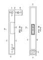
- FIG. 2Aillustrates one embodiment of an RFID apparatus 200 according to the present invention that is adapted for mechanisms that tighten the wristband around a wearer's wrist or ankle.
- the apparatusincludes a band portion 202 including a plurality of adjustment holes 204 , a tightening locking mechanism 208 , and an RFID circuit 210 .
- the RFID circuit 210includes a radio frequency identification (RFID) transponder chip 212 , and an antenna element 214 .
- the antenna element 214is coupled to an electrically conductive loop 216 that preferably runs down the length of the band portion 202 and preferably closely surrounding each of the adjustment holes 204 .
- the RFID apparatus 200includes a hole 222 into which a tightening mechanism 208 may fit.
- an exemplary tightening mechanismincludes a housing 300 having an entrance opening 302 at a first end and an exit opening 304 at an opposite end thereof. Openings 302 , 304 are dimensioned to allow a tail 220 of band 202 to pass therethrough.
- a first series of projections 228are disposed within housing 300 and extend towards a path defined by openings 302 , 304 .
- a second series of projections 306extends generally towards projections 228 .
- Projections 228 and 306are in substantially facing relationship across a gap b. Gap b being sized, and projections 228 , 306 being disposed to engage holes 204 as tail 220 moves in the direction of arrow A through housing 300 .
- projections 228 , 306are angled in the downstream direction of arrow A.
- Housing 300may be a fit onto band portion 202 through an extension 224 formed on a bottom portion of the tightening mechanism housing 300 extending through hole 222 and secured by a snap 226 .
- the tail 220 of band 202is inserted into the tightening mechanism 208 , such that the tail 220 fits into an interior portion of the tightening mechanism 208 .
- Projections 228 , 306are angled inward to engage portions of the tail 220 as it is inserted therein in the direction of arrow A and tightened against the wearer's wrist or ankle.
- the tightening mechanism 208 arrangementthus permits or provides an RFID bracelet 200 that can be tightened against a wearer's wrist or ankle without necessarily severing the electrically conductive loop 216 .
- the projections 228 , 306 inside the tightening mechanism 208engage respective adjacent ones of the holes 204 as the tail 220 is drawn through the tightening mechanism 208 .
- the projections 228 , 306may deflect in the direction of arrow A, but are rigid in the opposite direction. Any attempt by the wearer to remove the apparatus 200 by pushing and/or pulling the band portion 202 back through the tightening mechanism 208 in a direction opposite to arrow A with sufficient force will thus cause damage to its respective hole 204 , thereby rupturing the adjacent portion of the electrically conductive loop 216 .
- the RFID chip 212becomes disabled once the electrically conductive loop 216 becomes ruptured or severed.
- angled camming type of projectionis shown by way of example. However, any type of projection which deflects more easily in one (specific) direction than another may be used.
- the tightening mechanism 208can be a ratchet and pawl type assembly wherein the holes 204 are replaced by a series of teeth along a length of the band 202 .
- the teethcan engage the ratchet and pawl type assembly in a one way direction thereby allowing the apparatus to be tightened to a wearer, but do not allow movement in the reverse direction damaging the RFID circuit.
- the wearercan return the bracelet to authorized personnel and receive the wearer's deposit back.
- the RFID function of the apparatuswill become disabled once the release mechanism is engaged, such as by software, to allow removal of the apparatus.
- the RFID functioncan only be enabled by authorized personnel.
- FIGS. 3A and 3Bshow a flow diagram of a method of using the adjustable RFID apparatus 200 shown in FIGS. 2A and 2B or even other potentially differently configured adjustable wristbands in order to prevent unauthorized use of unauthorized removed or discarded bracelets.
- a personrequests access to an RFID apparatus 200 for a particular purpose, such as authorized purchases, entry to a restricted area, and/or exit and reentry to a venue. For example, the age of a person is verified in the connection of purchasing alcoholic beverages, whereas a guest list could be checked to determine if the person has access to a restriction area.
- the systemwould know that the person had previously been checked by an authorized party and would grant reentry to the venue.
- an RFID apparatus 200is issued (granted) if access to a venue is authorized for such purposes (step 310 ). Access is denied if the apparatus is not authorized.
- step 320the person (wearer) or an authorized person attaches the RFID bracelet to the requesting wearer's wrist or ankle.
- An authorized personwho may be different from the authorized person of step 320 , verifies the credentials of the wearer of the bracelet 200 (step 330 ). For example, at a venue where some patrons may be entitled to access alcoholic beverages and others may not, alcoholic beverage dispensing personnel may verify the credentials of the particular person.
- the authorized persontightens the bracelet 200 snugly against the wearer of the bracelet 200 (step 340 ). The authorized person should tighten the bracelet snugly enough so that the bracelet 200 cannot be slid off the wrist or ankle without incurring the aforementioned damage.
- the bracelet 200is tightened sufficiently against the wrist or ankle of the wearer so that any attempt to remove the bracelet 200 by backing the tail 220 of the band portion 202 out of tightening mechanism 208 in a direction opposite to arrow A will cause damage to the electrically conductive loop 216 adjacent to one or more of the holes 204 .
- This processthus prevents a situation which might otherwise occur when an unauthorized person, such as someone under legal drinking age obtains access to an older person's alcohol-authorized bracelet 200 , who only secured it loosely to their wrist and then subsequently slipped the wristband off of the wrist and handed it to an unauthorized person.
- the individual wearing bracelet 200is authorized for access to the appropriate limited services, such as the service of alcoholic beverages.
- An optional security measurecan include updating a data field that indicates the credentials of the wearer have been verified and that the bracelet 200 has been tightened by an authorized person. At this point, the individual wearing bracelet 200 is authorized for access to the appropriate limited services, such as the service of alcoholic beverages. However, the bracelet 200 is checked for validity (step 360 ) each time the wearer tries to engage in such limited services.
- a wristband with tightening capabilitiescan be used, such as a wristband with a generic single-use adhesive or barbed-peg and hole closure mechanism.
- the authorized personwould instead visually inspect the apparatus to ensure that it is adequately attached to the wearer. If the apparatus is not adequately attached, such as if there is a cut in the band or if it is on too loosely attached, the authorized person would replace the apparatus before issuing the individual authorization.
- the optional security measure(step 350 ) can subsequently be entered.
- the validity (step 360 ) of the bracelet 200can be checked by either visually inspecting the bracelet 200 for tears by an authorized person or electronically inspecting the bracelet 200 utilizing an RFID reading system. Utilizing an RFID reading system, the bracelet 200 is placed in proximity to an RFID reader. If the bracelet 200 is functional (not tampered with), the reader reads identification information associated with the bracelet 200 . Next, a database may be searched using the identification information of the bracelet to determine if the data field has been updated indicating the credentials have been verified and the apparatus has been tightened to the wearer. If the data field has been updated, the intended purpose (use) of the bracelet 200 is allowed.
- the wearermay wish to remove the bracelet 200 (step 380 ).
- the RFID functionality of the bracelet 200ceases to operate.
- a predetermined time limit or spending limitmay be associated with the bracelet 200 which when reached will also deactivate the RFID functionality of the bracelet 200 .
- the data field updating stepcan be performed by accessing data that is stored on an Electrically Erasable Programmable Read-Only Memory (EEPROM) within the bracelet 200 specifically within the RFID chip 212 and/or accessing a database while the bracelet 200 is in the vicinity of a reader.
- EEPROMElectrically Erasable Programmable Read-Only Memory
- projections 228 of the tightening mechanism 208are formed with a thick enough portion of material and/or physically stronger materials than the materials used to form the bracelet 200 . This guarantees that the bracelet 200 will break prior to individual projections 228 breaking, thus further ensuring that the electrically conductive loop 216 is disrupted when the bracelet is attempted to be removed or modified.
Landscapes
- Physics & Mathematics (AREA)
- General Physics & Mathematics (AREA)
- Engineering & Computer Science (AREA)
- Health & Medical Sciences (AREA)
- Child & Adolescent Psychology (AREA)
- General Health & Medical Sciences (AREA)
- Computer Security & Cryptography (AREA)
- Computer Hardware Design (AREA)
- Business, Economics & Management (AREA)
- Emergency Management (AREA)
- Automation & Control Theory (AREA)
- Electromagnetism (AREA)
- Microelectronics & Electronic Packaging (AREA)
- Theoretical Computer Science (AREA)
- General Engineering & Computer Science (AREA)
- Burglar Alarm Systems (AREA)
- Emergency Alarm Devices (AREA)
- Near-Field Transmission Systems (AREA)
Abstract
Description
Claims (19)
Priority Applications (1)
| Application Number | Priority Date | Filing Date | Title |
|---|---|---|---|
| US11/245,482US7388493B2 (en) | 2004-10-08 | 2005-10-06 | Method and system for preventing unauthorized removal and use of an RFID apparatus |
Applications Claiming Priority (2)
| Application Number | Priority Date | Filing Date | Title |
|---|---|---|---|
| US61751804P | 2004-10-08 | 2004-10-08 | |
| US11/245,482US7388493B2 (en) | 2004-10-08 | 2005-10-06 | Method and system for preventing unauthorized removal and use of an RFID apparatus |
Publications (2)
| Publication Number | Publication Date |
|---|---|
| US20060087438A1 US20060087438A1 (en) | 2006-04-27 |
| US7388493B2true US7388493B2 (en) | 2008-06-17 |
Family
ID=36143165
Family Applications (2)
| Application Number | Title | Priority Date | Filing Date |
|---|---|---|---|
| US11/245,482Expired - Fee RelatedUS7388493B2 (en) | 2004-10-08 | 2005-10-06 | Method and system for preventing unauthorized removal and use of an RFID apparatus |
| US11/246,002Expired - Fee RelatedUS7168626B2 (en) | 2004-10-08 | 2005-10-07 | Identification band using shorting wire for enabling/disabling an RFID transponder contained thereon |
Family Applications After (1)
| Application Number | Title | Priority Date | Filing Date |
|---|---|---|---|
| US11/246,002Expired - Fee RelatedUS7168626B2 (en) | 2004-10-08 | 2005-10-07 | Identification band using shorting wire for enabling/disabling an RFID transponder contained thereon |
Country Status (2)
| Country | Link |
|---|---|
| US (2) | US7388493B2 (en) |
| WO (2) | WO2006042023A2 (en) |
Cited By (11)
| Publication number | Priority date | Publication date | Assignee | Title |
|---|---|---|---|---|
| US20050121898A1 (en)* | 2003-12-08 | 2005-06-09 | Infineon Technologies Ag | Authenticity tag and method for operating an authenticity tag |
| US20090296997A1 (en)* | 2008-06-03 | 2009-12-03 | James Rocheford | Method and apparatus for securing a computer |
| US20110043339A1 (en)* | 2009-08-19 | 2011-02-24 | Intelleflex Corporation | RF device with tamper detection |
| US20130254137A1 (en)* | 2007-07-31 | 2013-09-26 | Andrew Stuart HUNT | Advertising and Marketing Method and Device |
| US8655732B1 (en)* | 2009-10-28 | 2014-02-18 | Mark Edward Wilinski | Liquid dispensation |
| US8773239B2 (en) | 2011-04-04 | 2014-07-08 | Integrated Monitoring Systems, Llc | Biometric identification system using pulse waveform |
| US9223298B2 (en) | 2011-04-04 | 2015-12-29 | Integrated Monitoring Systems, Llc | Biometric identification system using pulse waveform |
| US9274509B2 (en) | 2012-01-20 | 2016-03-01 | Integrated Monitoring Systems, Llc | System for biometric identity confirmation |
| US9398858B2 (en) | 2011-12-13 | 2016-07-26 | Integrated Monitoring Systems, Llc | System for biometric identity confirmation |
| US9575470B2 (en) | 2012-01-20 | 2017-02-21 | Integrated Monitoring Systems, Llc | System for biometric identity confirmation |
| US20180182217A1 (en)* | 2016-12-22 | 2018-06-28 | Em Microelectronic-Marin S.A. | Dual communication frequency rfid circuit equipped with a tamper-evident loop |
Families Citing this family (85)
| Publication number | Priority date | Publication date | Assignee | Title |
|---|---|---|---|---|
| US6797950B2 (en)* | 2002-02-04 | 2004-09-28 | Thermo Finnegan Llc | Two-dimensional quadrupole ion trap operated as a mass spectrometer |
| US20070060358A1 (en) | 2005-08-10 | 2007-03-15 | Amaitis Lee M | System and method for wireless gaming with location determination |
| US8616967B2 (en) | 2004-02-25 | 2013-12-31 | Cfph, Llc | System and method for convenience gaming |
| US8092303B2 (en) | 2004-02-25 | 2012-01-10 | Cfph, Llc | System and method for convenience gaming |
| US7534169B2 (en) | 2005-07-08 | 2009-05-19 | Cfph, Llc | System and method for wireless gaming system with user profiles |
| US7637810B2 (en) | 2005-08-09 | 2009-12-29 | Cfph, Llc | System and method for wireless gaming system with alerts |
| US7304578B1 (en)* | 2005-06-02 | 2007-12-04 | Hewlett-Packard Development Company, L.P. | Tag including RFID circuit storing data modifiable using a physically alterable medium |
| US10510214B2 (en) | 2005-07-08 | 2019-12-17 | Cfph, Llc | System and method for peer-to-peer wireless gaming |
| US8070604B2 (en) | 2005-08-09 | 2011-12-06 | Cfph, Llc | System and method for providing wireless gaming as a service application |
| US7327261B2 (en)* | 2005-07-27 | 2008-02-05 | Zih Corp. | Visual identification tag deactivation |
| US7377447B2 (en)* | 2005-12-05 | 2008-05-27 | Rcd Technology, Inc. | Tuned radio frequency identification (RFID) circuit used as a security device for wristbands and package security |
| US8535714B2 (en) | 2006-01-06 | 2013-09-17 | Acelrx Pharmaceuticals, Inc. | Small volume oral transmucosal dosage forms containing sufentanil for treatment of pain |
| US8252329B2 (en) | 2007-01-05 | 2012-08-28 | Acelrx Pharmaceuticals, Inc. | Bioadhesive drug formulations for oral transmucosal delivery |
| US9066847B2 (en)* | 2007-01-05 | 2015-06-30 | Aceirx Pharmaceuticals, Inc. | Storage and dispensing devices for administration of oral transmucosal dosage forms |
| US8865743B2 (en) | 2006-01-06 | 2014-10-21 | Acelrx Pharmaceuticals, Inc. | Small volume oral transmucosal dosage forms containing sufentanil for treatment of pain |
| US8252328B2 (en) | 2006-01-06 | 2012-08-28 | Acelrx Pharmaceuticals, Inc. | Bioadhesive drug formulations for oral transmucosal delivery |
| US8357114B2 (en) | 2006-01-06 | 2013-01-22 | Acelrx Pharmaceuticals, Inc. | Drug dispensing device with flexible push rod |
| US8202535B2 (en) | 2006-01-06 | 2012-06-19 | Acelrx Pharmaceuticals, Inc. | Small-volume oral transmucosal dosage forms |
| US8753308B2 (en) | 2006-01-06 | 2014-06-17 | Acelrx Pharmaceuticals, Inc. | Methods for administering small volume oral transmucosal dosage forms using a dispensing device |
| US9289583B2 (en)* | 2006-01-06 | 2016-03-22 | Acelrx Pharmaceuticals, Inc. | Methods for administering small volume oral transmucosal dosage forms using a dispensing device |
| US7644861B2 (en) | 2006-04-18 | 2010-01-12 | Bgc Partners, Inc. | Systems and methods for providing access to wireless gaming devices |
| US7549576B2 (en)* | 2006-05-05 | 2009-06-23 | Cfph, L.L.C. | Systems and methods for providing access to wireless gaming devices |
| US8939359B2 (en)* | 2006-05-05 | 2015-01-27 | Cfph, Llc | Game access device with time varying signal |
| US12136314B2 (en) | 2006-05-05 | 2024-11-05 | Cfph, Llc | Game access device with time varying signal |
| US20070260491A1 (en)* | 2006-05-08 | 2007-11-08 | Pamela Palmer | System for delivery and monitoring of administration of controlled substances |
| US20070299687A1 (en)* | 2006-06-23 | 2007-12-27 | Pamela Palmer | Inpatient system for patient-controlled delivery of oral transmucosal medications dosed as needed |
| US9306952B2 (en) | 2006-10-26 | 2016-04-05 | Cfph, Llc | System and method for wireless gaming with location determination |
| US8292741B2 (en) | 2006-10-26 | 2012-10-23 | Cfph, Llc | Apparatus, processes and articles for facilitating mobile gaming |
| GB0621428D0 (en)* | 2006-10-27 | 2006-12-06 | Tymatic Ltd | Consumables authentication |
| USD571346S1 (en)* | 2006-10-27 | 2008-06-17 | D B Industries, Inc. | Radio frequency identification tag |
| US8645709B2 (en) | 2006-11-14 | 2014-02-04 | Cfph, Llc | Biometric access data encryption |
| US8510567B2 (en) | 2006-11-14 | 2013-08-13 | Cfph, Llc | Conditional biometric access in a gaming environment |
| US9411944B2 (en) | 2006-11-15 | 2016-08-09 | Cfph, Llc | Biometric access sensitivity |
| US8319601B2 (en) | 2007-03-14 | 2012-11-27 | Cfph, Llc | Game account access device |
| US8581721B2 (en) | 2007-03-08 | 2013-11-12 | Cfph, Llc | Game access device with privileges |
| US9183693B2 (en)* | 2007-03-08 | 2015-11-10 | Cfph, Llc | Game access device |
| US7876222B2 (en)* | 2007-08-30 | 2011-01-25 | Symbol Technologies, Inc. | Customizable mechanically programmable RFID tags |
| GB2453971B (en)* | 2007-10-24 | 2010-01-27 | Matthew John Stallard | A reusable band, secured using a lock and key |
| TW201001958A (en) | 2008-04-29 | 2010-01-01 | Odin Technologies Inc | Method and apparatus for a deployable radio-frequency identification portal system |
| US20100102131A1 (en)* | 2008-10-28 | 2010-04-29 | First Data Corporation | Systems and Methods for Disabling a Contactless Transaction Device |
| US20100102123A1 (en)* | 2008-10-28 | 2010-04-29 | First Data Corporation | Systems, Methods, and Apparatus for Facilitating Access to Medical Information |
| US8550361B2 (en)* | 2008-10-28 | 2013-10-08 | First Data Corporation | Systems, methods, and apparatus to facilitate locating a user of a transaction device |
| US10803515B2 (en)* | 2008-10-31 | 2020-10-13 | First Data Corporation | Systems, methods, and apparatus for using a contactless transaction device reader with a computing system |
| US8945592B2 (en) | 2008-11-21 | 2015-02-03 | Acelrx Pharmaceuticals, Inc. | Sufentanil solid dosage forms comprising oxygen scavengers and methods of using the same |
| US8395521B2 (en)* | 2009-02-06 | 2013-03-12 | University Of Dayton | Smart aerospace structures |
| US20150015368A1 (en)* | 2013-07-15 | 2015-01-15 | Michael D. Roth | Passive ignition interlock identification apparatus and method of use thereof |
| US8548623B2 (en) | 2009-03-18 | 2013-10-01 | Acelrx Pharmaceuticals, Inc. | Storage and dispensing devices for administration of oral transmucosal dosage forms |
| US20100326219A1 (en)* | 2009-05-12 | 2010-12-30 | Band-It-Idex, Inc. | Band Clamp With Embedded Electronics |
| US8500031B2 (en) | 2010-07-29 | 2013-08-06 | Bank Of America Corporation | Wearable article having point of sale payment functionality |
| US9177307B2 (en) | 2010-07-29 | 2015-11-03 | Bank Of America Corporation | Wearable financial indicator |
| US8956231B2 (en) | 2010-08-13 | 2015-02-17 | Cfph, Llc | Multi-process communication regarding gaming information |
| US8974302B2 (en) | 2010-08-13 | 2015-03-10 | Cfph, Llc | Multi-process communication regarding gaming information |
| US20220296999A1 (en) | 2010-08-13 | 2022-09-22 | Cfph, Llc | Multi-process communication regarding gaming information |
| US8991709B2 (en)* | 2010-08-30 | 2015-03-31 | Tagstar Systems Gmbh | Tamper-proof RFID label |
| US9477922B2 (en) | 2010-09-01 | 2016-10-25 | Quake Global, Inc. | UHF RFID wristband with a long read range |
| WO2014134157A1 (en) | 2013-02-26 | 2014-09-04 | Quake Global, Inc. | Methods and apparatus for automatic identification wristband |
| US8771185B2 (en)* | 2010-12-22 | 2014-07-08 | Sleepsafe Drivers, Inc. | System and method for reliable sleep diagnostic testing |
| US20120261468A1 (en)* | 2011-04-14 | 2012-10-18 | Thomas Colucci Hecht | System and method for providing verification of age or other attributes in an alcohol serving environment |
| GB2493704B (en) | 2011-08-11 | 2013-09-18 | G4S Monitoring Technologies Ltd | Personal identification system |
| US20130135104A1 (en)* | 2011-11-29 | 2013-05-30 | Upm Rfid Oy | Radio-frequency transponder comprising a tamper loop functionality |
| CA2773150C (en)* | 2012-03-30 | 2021-10-26 | Guard Rfid Solutions Inc. | Anti-tamper conductive plastic band for rfid tag |
| US9841492B2 (en) | 2013-02-25 | 2017-12-12 | Quake Global, Inc. | Ceiling-mounted RFID-enabled tracking |
| US8893976B1 (en) | 2013-07-18 | 2014-11-25 | Automated Assembly Corporation | Tamper-resistant electronic system |
| US20150109107A1 (en)* | 2013-10-20 | 2015-04-23 | VenGo, LLC | System for Holding Multiple RFIDs in a Wearable Device |
| US20150109106A1 (en)* | 2013-10-20 | 2015-04-23 | VenGo, LLC | System for Holding an RFID within a Slotted Wearable Device |
| US10540649B2 (en)* | 2014-05-20 | 2020-01-21 | Intellitix Technologies, Inc. | Wearable RFID device for use in an event-based interrogation zone |
| WO2016025755A1 (en) | 2014-08-13 | 2016-02-18 | R.R. Donnelley & Sons Company | Method and apparatus for producing an electronic device |
| EP3183693B1 (en) | 2014-08-19 | 2018-08-29 | R. R. Donnelley & Sons Company | Apparatus and method for monitoring a package during transit |
| US10083391B2 (en)* | 2015-09-21 | 2018-09-25 | Cutaneous Information Technologies Llc | Visually, optically and electronically readable frangible device for affixation to the skin |
| US9965658B2 (en)* | 2015-06-16 | 2018-05-08 | Motorola Mobility Llc | Person-centric activation of radio frequency identification (RFID) tag |
| US9691303B2 (en) | 2015-09-14 | 2017-06-27 | R.R. Donnelley & Sons Company | Electronic label having a timer function |
| WO2017120226A1 (en) | 2016-01-04 | 2017-07-13 | R.R. Donnelley & Sons Company | Multiple detector apparatus and method for monitoring an environment |
| US9785881B2 (en) | 2016-02-15 | 2017-10-10 | R.R. Donnelley & Sons Company | System and method for producing an electronic device |
| FR3049394A1 (en)* | 2016-03-25 | 2017-09-29 | Orange | PORTABLE OBJECT AND ITS ANTENNA NFC |
| US10342136B2 (en) | 2016-09-23 | 2019-07-02 | R.R. Donnelley & Sons Company | Monitoring device |
| RU2639577C1 (en)* | 2016-10-13 | 2017-12-21 | Акционерное общество "Пэй Ринг" | Non-contact smart-card |
| US10445692B2 (en) | 2017-03-06 | 2019-10-15 | Cryovac, Llc | Monitoring device and method of operating a monitoring device to transmit data |
| US11240916B2 (en) | 2017-05-31 | 2022-02-01 | Cryovac, Llc | Electronic device, method and apparatus for producing an electronic device, and composition therefor |
| US11797819B2 (en)* | 2017-09-20 | 2023-10-24 | Avery Dennison Retail Information Services Llc | RFID wristband |
| US11928541B2 (en)* | 2018-11-12 | 2024-03-12 | Stmicroelectronics (Rousset) Sas | Device and method for detecting opening of or an attempt to open a closed container |
| US10480909B1 (en) | 2018-12-28 | 2019-11-19 | LEEB Innovations, LLC | Prisoner control device, system, and method |
| USD926254S1 (en)* | 2019-10-01 | 2021-07-27 | D.C. Premier Sales, Inc. | Band |
| USD979650S1 (en)* | 2020-06-23 | 2023-02-28 | Michael McKnight | Wearable advertisement device |
| GB2602140A (en) | 2020-12-18 | 2022-06-22 | Buddi Ltd | A wearable device |
| EP4206985A1 (en)* | 2021-12-29 | 2023-07-05 | EM Microelectronic-Marin SA | Tamper-evident rfid tag and method thereof |
Citations (25)
| Publication number | Priority date | Publication date | Assignee | Title |
|---|---|---|---|---|
| US4833807A (en) | 1987-12-04 | 1989-05-30 | Panorama Plastics Ltd. | Lockable security identification wriststrap |
| US4980671A (en) | 1989-04-26 | 1990-12-25 | Guardian Technologies, Inc. | Remote confinement system with timed tamper signal reset |
| US5448846A (en) | 1992-04-09 | 1995-09-12 | Precision Dynamics Corporation | Identification device for machine imprinting |
| US5457906A (en) | 1992-11-19 | 1995-10-17 | Precision Dynamics Corporation | Adhesive closure for identification band and method |
| US5471197A (en) | 1993-02-19 | 1995-11-28 | Cincinnati Microwave, Inc. | Tamper-proof bracelet for home arrest system |
| US5504474A (en) | 1994-07-18 | 1996-04-02 | Elmo Tech Ltd. | Tag for electronic personnel monitoring |
| US5883576A (en)* | 1998-01-14 | 1999-03-16 | De La Huerga; Carlos | Identification bracelet with electronics information |
| US5973598A (en) | 1997-09-11 | 1999-10-26 | Precision Dynamics Corporation | Radio frequency identification tag on flexible substrate |
| US5973600A (en) | 1997-09-11 | 1999-10-26 | Precision Dynamics Corporation | Laminated radio frequency identification device |
| US5979941A (en)* | 1996-11-19 | 1999-11-09 | Mosher, Jr.; Walter W. | Linkage identification system |
| US6043746A (en) | 1999-02-17 | 2000-03-28 | Microchip Technology Incorporated | Radio frequency identification (RFID) security tag for merchandise and method therefor |
| US6050622A (en) | 1991-12-19 | 2000-04-18 | Gustafson; Ake | Safety sealing device |
| US6211790B1 (en) | 1999-05-19 | 2001-04-03 | Elpas North America, Inc. | Infant and parent matching and security system and method of matching infant and parent |
| US6236319B1 (en) | 1998-07-31 | 2001-05-22 | Beryl E. Pitzer | Personal monitoring system |
| US6255951B1 (en) | 1996-12-20 | 2001-07-03 | Carlos De La Huerga | Electronic identification bracelet |
| US6346886B1 (en) | 1996-12-20 | 2002-02-12 | Carlos De La Huerga | Electronic identification apparatus |
| US20020067264A1 (en) | 2000-03-15 | 2002-06-06 | Soehnlen John Pius | Tamper Evident Radio Frequency Identification System And Package |
| US20020084904A1 (en) | 1996-12-20 | 2002-07-04 | Carlos De La Huerga | Electronic identification apparatus |
| US6421013B1 (en) | 1999-10-04 | 2002-07-16 | Amerasia International Technology, Inc. | Tamper-resistant wireless article including an antenna |
| US6431455B1 (en) | 1998-07-21 | 2002-08-13 | Skidata Ag | Contactless data carrier |
| US20030075608A1 (en) | 2000-03-21 | 2003-04-24 | Atherton Peter S | Tamper indicating radio frequency identification label |
| US20030173408A1 (en)* | 2002-03-18 | 2003-09-18 | Precision Dynamics Corporation | Enhanced identification appliance |
| US6693543B1 (en) | 1999-05-05 | 2004-02-17 | Guidance Control Systems Limited | Tagging device |
| US20040066296A1 (en) | 2001-11-15 | 2004-04-08 | Atherton Peter S. | Tamper indicating radio frequency identification label with tracking capability |
| US6782648B1 (en) | 1992-11-09 | 2004-08-31 | Precision Dynamics Corporation | Wristband having exposed adhesive fastener |
Family Cites Families (41)
| Publication number | Priority date | Publication date | Assignee | Title |
|---|---|---|---|---|
| US4835372A (en) | 1985-07-19 | 1989-05-30 | Clincom Incorporated | Patient care system |
| US4885571A (en) | 1986-04-15 | 1989-12-05 | B. I. Incorperated | Tag for use with personnel monitoring system |
| US4736196A (en) | 1986-11-18 | 1988-04-05 | Cost-Effective Monitoring Systems, Co. | Electronic monitoring system |
| US4800543A (en) | 1987-12-03 | 1989-01-24 | Ramtron Corporation | Timepiece communication system |
| US4973944A (en) | 1989-05-19 | 1990-11-27 | Maletta Gabriel J | Electrical signal and alarm protection proximity device |
| US5115223A (en)* | 1990-09-20 | 1992-05-19 | Moody Thomas O | Personnel location monitoring system and method |
| CA2055266C (en) | 1991-11-12 | 2000-03-14 | Brian Wayne Martin | Fibre optic security and communications link |
| US5612675A (en) | 1993-10-08 | 1997-03-18 | Intellitech International, Inc. | Anti-removal monitoring device |
| US5430441A (en) | 1993-10-12 | 1995-07-04 | Motorola, Inc. | Transponding tag and method |
| US5423574A (en) | 1993-12-10 | 1995-06-13 | Forte-Pathroff; Denise | Child loss prevention system and method of use |
| US6349493B1 (en) | 1994-01-03 | 2002-02-26 | Moore Business Forms, Inc. | Debit wristbands |
| US5364133A (en) | 1994-01-12 | 1994-11-15 | Zebra Technologies Corporation | Identification bracelet |
| US6474557B2 (en) | 2000-10-23 | 2002-11-05 | Busch Entertainment Corporation | Prepayment wristband and computer debit system |
| US6142368A (en) | 1994-03-03 | 2000-11-07 | Busch Entertainment Corporation | Prepayment wristband and computer debit system |
| US5512879A (en) | 1994-07-25 | 1996-04-30 | Stokes; John H. | Apparatus to prevent infant kidnappings and mixups |
| US6072396A (en) | 1994-12-30 | 2000-06-06 | Advanced Business Sciences | Apparatus and method for continuous electronic monitoring and tracking of individuals |
| US5781442A (en) | 1995-05-15 | 1998-07-14 | Alaris Medical Systems, Inc. | System and method for collecting data and managing patient care |
| US5627520A (en) | 1995-07-10 | 1997-05-06 | Protell Systems International, Inc. | Tamper detect monitoring device |
| AU6648296A (en) | 1995-07-20 | 1997-02-18 | Dallas Semiconductor Corporation | An electronic micro identification circuit that is inherently bonded to a someone or something |
| US5998858A (en) | 1995-07-20 | 1999-12-07 | Dallas Semiconductor Corporation | Microcircuit with memory that is protected by both hardware and software |
| JP3245028B2 (en) | 1995-10-31 | 2002-01-07 | 株式会社サンプラテック | Recognition band |
| US6434158B1 (en) | 1996-10-15 | 2002-08-13 | Motorola, Inc. | Entryway system using proximity-based short-range wireless links |
| US6434159B1 (en) | 1996-10-15 | 2002-08-13 | Motorola, Inc. | Transaction system and method therefor |
| US6424623B1 (en) | 1996-10-15 | 2002-07-23 | Motorola, Inc. | Virtual queuing system using proximity-based short-range wireless links |
| CA2268951A1 (en) | 1996-10-17 | 1998-04-23 | Pinpoint Corporation | Article tracking system |
| US5831535A (en) | 1997-07-24 | 1998-11-03 | Elmo-Tech Ltd. | Electronic monitoring device and monitoring system including same |
| US5977877A (en)* | 1998-05-18 | 1999-11-02 | Instantel Inc. | Multiple conductor security tag |
| US6107920A (en) | 1998-06-09 | 2000-08-22 | Motorola, Inc. | Radio frequency identification tag having an article integrated antenna |
| US6104295A (en)* | 1998-07-20 | 2000-08-15 | Versus Technology, Inc. | Electronic band tag and method of storing ID information therein |
| US6144303A (en) | 1999-02-01 | 2000-11-07 | Exi Wireless Systems, Inc. | Tag and system for patient safety monitoring |
| GB9911878D0 (en) | 1999-05-22 | 1999-07-21 | Marconi Electronic Syst Ltd | Identification tag |
| US6335907B1 (en) | 1999-07-23 | 2002-01-01 | Robert Momich | Package with integrated circuit chip embedded therein and system for using same |
| JP2001088789A (en) | 1999-09-24 | 2001-04-03 | Yamaha Motor Co Ltd | Burglary preventive device of small propulsion vessel |
| US6472989B2 (en) | 2000-02-29 | 2002-10-29 | Frederick H. Roy, Jr. | Child protection bracelet |
| US20020007292A1 (en) | 2000-03-28 | 2002-01-17 | Paxton Mark S. | Method and apparatus for reserving a place in line |
| US6384727B1 (en) | 2000-08-02 | 2002-05-07 | Motorola, Inc. | Capacitively powered radio frequency identification device |
| US20020049656A1 (en) | 2000-09-29 | 2002-04-25 | Lancos Kenneth J. | System and method for providing monetary credits to a guest within a coverage area |
| US20020070865A1 (en) | 2000-09-29 | 2002-06-13 | Lancos Kenneth J. | System and method for creating a group of guests at a coverage area |
| US20020082897A1 (en) | 2000-12-26 | 2002-06-27 | Douglas Menelly | Method and apparatus for facilitating amusement park activities and storing demographic information |
| EP1246152B1 (en) | 2001-03-28 | 2008-11-19 | Latschbacher GmbH | Marking device for wooden objects, in particular for tree trunks |
| US7042357B2 (en)* | 2003-03-26 | 2006-05-09 | Proximities, Inc. | Non-reusable identification device |
- 2005
- 2005-10-06USUS11/245,482patent/US7388493B2/ennot_activeExpired - Fee Related
- 2005-10-07USUS11/246,002patent/US7168626B2/ennot_activeExpired - Fee Related
- 2005-10-07WOPCT/US2005/036000patent/WO2006042023A2/enactiveApplication Filing
- 2005-10-07WOPCT/US2005/036432patent/WO2006039722A2/enactiveApplication Filing
Patent Citations (26)
| Publication number | Priority date | Publication date | Assignee | Title |
|---|---|---|---|---|
| US4833807A (en) | 1987-12-04 | 1989-05-30 | Panorama Plastics Ltd. | Lockable security identification wriststrap |
| US4980671A (en) | 1989-04-26 | 1990-12-25 | Guardian Technologies, Inc. | Remote confinement system with timed tamper signal reset |
| US6050622A (en) | 1991-12-19 | 2000-04-18 | Gustafson; Ake | Safety sealing device |
| US5448846A (en) | 1992-04-09 | 1995-09-12 | Precision Dynamics Corporation | Identification device for machine imprinting |
| US6782648B1 (en) | 1992-11-09 | 2004-08-31 | Precision Dynamics Corporation | Wristband having exposed adhesive fastener |
| US5457906A (en) | 1992-11-19 | 1995-10-17 | Precision Dynamics Corporation | Adhesive closure for identification band and method |
| US5471197A (en) | 1993-02-19 | 1995-11-28 | Cincinnati Microwave, Inc. | Tamper-proof bracelet for home arrest system |
| US5504474A (en) | 1994-07-18 | 1996-04-02 | Elmo Tech Ltd. | Tag for electronic personnel monitoring |
| US5979941A (en)* | 1996-11-19 | 1999-11-09 | Mosher, Jr.; Walter W. | Linkage identification system |
| US6255951B1 (en) | 1996-12-20 | 2001-07-03 | Carlos De La Huerga | Electronic identification bracelet |
| US6346886B1 (en) | 1996-12-20 | 2002-02-12 | Carlos De La Huerga | Electronic identification apparatus |
| US20020084904A1 (en) | 1996-12-20 | 2002-07-04 | Carlos De La Huerga | Electronic identification apparatus |
| US5973598A (en) | 1997-09-11 | 1999-10-26 | Precision Dynamics Corporation | Radio frequency identification tag on flexible substrate |
| US5973600A (en) | 1997-09-11 | 1999-10-26 | Precision Dynamics Corporation | Laminated radio frequency identification device |
| US5883576A (en)* | 1998-01-14 | 1999-03-16 | De La Huerga; Carlos | Identification bracelet with electronics information |
| US6431455B1 (en) | 1998-07-21 | 2002-08-13 | Skidata Ag | Contactless data carrier |
| US6236319B1 (en) | 1998-07-31 | 2001-05-22 | Beryl E. Pitzer | Personal monitoring system |
| US6043746A (en) | 1999-02-17 | 2000-03-28 | Microchip Technology Incorporated | Radio frequency identification (RFID) security tag for merchandise and method therefor |
| US6693543B1 (en) | 1999-05-05 | 2004-02-17 | Guidance Control Systems Limited | Tagging device |
| US6211790B1 (en) | 1999-05-19 | 2001-04-03 | Elpas North America, Inc. | Infant and parent matching and security system and method of matching infant and parent |
| US6421013B1 (en) | 1999-10-04 | 2002-07-16 | Amerasia International Technology, Inc. | Tamper-resistant wireless article including an antenna |
| US20020067264A1 (en) | 2000-03-15 | 2002-06-06 | Soehnlen John Pius | Tamper Evident Radio Frequency Identification System And Package |
| US20030075608A1 (en) | 2000-03-21 | 2003-04-24 | Atherton Peter S | Tamper indicating radio frequency identification label |
| US6888509B2 (en) | 2000-03-21 | 2005-05-03 | Mikoh Corporation | Tamper indicating radio frequency identification label |
| US20040066296A1 (en) | 2001-11-15 | 2004-04-08 | Atherton Peter S. | Tamper indicating radio frequency identification label with tracking capability |
| US20030173408A1 (en)* | 2002-03-18 | 2003-09-18 | Precision Dynamics Corporation | Enhanced identification appliance |
Cited By (15)
| Publication number | Priority date | Publication date | Assignee | Title |
|---|---|---|---|---|
| US20080073437A1 (en)* | 2003-12-08 | 2008-03-27 | Infineon Technologies Ag | Method for operating an authenticity tag |
| US7893832B2 (en) | 2003-12-08 | 2011-02-22 | Infineon Technologies Ag | Authenticity tag and method for operating an authenticity tag |
| US20050121898A1 (en)* | 2003-12-08 | 2005-06-09 | Infineon Technologies Ag | Authenticity tag and method for operating an authenticity tag |
| US20130254137A1 (en)* | 2007-07-31 | 2013-09-26 | Andrew Stuart HUNT | Advertising and Marketing Method and Device |
| US20090296997A1 (en)* | 2008-06-03 | 2009-12-03 | James Rocheford | Method and apparatus for securing a computer |
| US9082057B2 (en)* | 2009-08-19 | 2015-07-14 | Intelleflex Corporation | RF device with tamper detection |
| US20110043339A1 (en)* | 2009-08-19 | 2011-02-24 | Intelleflex Corporation | RF device with tamper detection |
| US8655732B1 (en)* | 2009-10-28 | 2014-02-18 | Mark Edward Wilinski | Liquid dispensation |
| US8773239B2 (en) | 2011-04-04 | 2014-07-08 | Integrated Monitoring Systems, Llc | Biometric identification system using pulse waveform |
| US9223298B2 (en) | 2011-04-04 | 2015-12-29 | Integrated Monitoring Systems, Llc | Biometric identification system using pulse waveform |
| US9398858B2 (en) | 2011-12-13 | 2016-07-26 | Integrated Monitoring Systems, Llc | System for biometric identity confirmation |
| US9274509B2 (en) | 2012-01-20 | 2016-03-01 | Integrated Monitoring Systems, Llc | System for biometric identity confirmation |
| US9575470B2 (en) | 2012-01-20 | 2017-02-21 | Integrated Monitoring Systems, Llc | System for biometric identity confirmation |
| US20180182217A1 (en)* | 2016-12-22 | 2018-06-28 | Em Microelectronic-Marin S.A. | Dual communication frequency rfid circuit equipped with a tamper-evident loop |
| US10152863B2 (en)* | 2016-12-22 | 2018-12-11 | Em Microelectronic-Marin S.A. | Dual communication frequency RFID circuit equipped with a tamper-evident loop |
Also Published As
| Publication number | Publication date |
|---|---|
| US20060087438A1 (en) | 2006-04-27 |
| US7168626B2 (en) | 2007-01-30 |
| WO2006042023A3 (en) | 2007-02-01 |
| WO2006039722A3 (en) | 2007-02-15 |
| US20060092028A1 (en) | 2006-05-04 |
| WO2006042023A2 (en) | 2006-04-20 |
| WO2006039722A2 (en) | 2006-04-13 |
Similar Documents
| Publication | Publication Date | Title |
|---|---|---|
| US7388493B2 (en) | Method and system for preventing unauthorized removal and use of an RFID apparatus | |
| US7286055B2 (en) | Tamper-resistant RFID disabling apparatus | |
| US8424716B2 (en) | Wristband applicator | |
| US7579950B2 (en) | Identification band using serpentine paths to detect tampering | |
| US7283054B2 (en) | Tamper-resistant RFID disabling apparatus and method of manufacturing | |
| US7535356B2 (en) | Identification band using a conductive fastening for enhanced security and functionality | |
| US7417541B2 (en) | Identification band with regions having electro-magnetically detectable regions | |
| CA2478677C (en) | Enhanced identification appliance | |
| US10332372B2 (en) | Security system and security tag assembly |
Legal Events
| Date | Code | Title | Description |
|---|---|---|---|
| AS | Assignment | Owner name:PROXIMITIES, INC., FLORIDA Free format text:ASSIGNMENT OF ASSIGNORS INTEREST;ASSIGNORS:LERCH, JOHN W.;GIRVIN, JOSHUA M.;REEL/FRAME:017109/0318 Effective date:20051031 | |
| AS | Assignment | Owner name:FLOMENHOFT, MARK J., FLORIDA Free format text:SECURITY AGREEMENT;ASSIGNOR:PROXIMITIES, INC.;REEL/FRAME:018194/0507 Effective date:20060811 | |
| AS | Assignment | Owner name:PROXIMITIES, INC., FLORIDA Free format text:RELEASE OF SECURITY INTEREST;ASSIGNOR:FLOMENHOFT, MARK J.;REEL/FRAME:020487/0639 Effective date:20071228 Owner name:BARTRONICS AMERICA, INC., CALIFORNIA Free format text:ASSIGNMENT OF ASSIGNORS INTEREST;ASSIGNOR:PROXIMITIES, INC.;REEL/FRAME:020491/0600 Effective date:20080109 | |
| CC | Certificate of correction | ||
| AS | Assignment | Owner name:BARTRONICS HONG KONG LIMITED, HONG KONG Free format text:ASSIGNMENT OF ASSIGNORS INTEREST;ASSIGNOR:BARTRONICS AMERICA, INC.;REEL/FRAME:026043/0622 Effective date:20110302 | |
| FEPP | Fee payment procedure | Free format text:PAT HOLDER CLAIMS SMALL ENTITY STATUS, ENTITY STATUS SET TO SMALL (ORIGINAL EVENT CODE: LTOS); ENTITY STATUS OF PATENT OWNER: SMALL ENTITY | |
| FPAY | Fee payment | Year of fee payment:4 | |
| SULP | Surcharge for late payment | ||
| REMI | Maintenance fee reminder mailed | ||
| LAPS | Lapse for failure to pay maintenance fees | ||
| STCH | Information on status: patent discontinuation | Free format text:PATENT EXPIRED DUE TO NONPAYMENT OF MAINTENANCE FEES UNDER 37 CFR 1.362 | |
| FP | Lapsed due to failure to pay maintenance fee | Effective date:20160617 |