US7387898B1 - Apparatus and method for conducting assays - Google Patents
Apparatus and method for conducting assaysDownload PDFInfo
- Publication number
- US7387898B1 US7387898B1US09/284,421US28442197AUS7387898B1US 7387898 B1US7387898 B1US 7387898B1US 28442197 AUS28442197 AUS 28442197AUS 7387898 B1US7387898 B1US 7387898B1
- Authority
- US
- United States
- Prior art keywords
- sector
- assay plate
- plate structure
- wells
- insert
- Prior art date
- Legal status (The legal status is an assumption and is not a legal conclusion. Google has not performed a legal analysis and makes no representation as to the accuracy of the status listed.)
- Expired - Fee Related
Links
- 238000003556assayMethods0.000titleclaimsabstractdescription69
- 238000000034methodMethods0.000titleabstractdescription15
- 239000012530fluidSubstances0.000claimsabstractdescription66
- 230000003287optical effectEffects0.000claimsabstractdescription28
- 229920003023plasticPolymers0.000claimsabstractdescription6
- 239000007788liquidSubstances0.000claimsdescription47
- 238000006243chemical reactionMethods0.000claimsdescription31
- 238000007689inspectionMethods0.000claimsdescription8
- 230000002093peripheral effectEffects0.000claimsdescription8
- 239000004033plasticSubstances0.000claimsdescription5
- 230000009471actionEffects0.000claimsdescription4
- 238000001514detection methodMethods0.000claimsdescription2
- 230000037431insertionEffects0.000claims3
- 238000003780insertionMethods0.000claims3
- 238000000576coating methodMethods0.000claims2
- 239000011248coating agentSubstances0.000claims1
- 230000002209hydrophobic effectEffects0.000claims1
- 238000012360testing methodMethods0.000abstractdescription16
- 238000003018immunoassayMethods0.000abstractdescription9
- 239000000126substanceSubstances0.000abstractdescription9
- 238000010256biochemical assayMethods0.000abstractdescription7
- 238000001356surgical procedureMethods0.000abstractdescription2
- 230000002068genetic effectEffects0.000abstract1
- 239000000427antigenSubstances0.000description21
- 102000036639antigensHuman genes0.000description20
- 108091007433antigensProteins0.000description20
- 239000003153chemical reaction reagentSubstances0.000description15
- 239000012491analyteSubstances0.000description11
- 125000006850spacer groupChemical group0.000description8
- 239000000758substrateSubstances0.000description7
- 230000008569processEffects0.000description6
- 230000000717retained effectEffects0.000description6
- 238000005406washingMethods0.000description6
- 108091003079Bovine Serum AlbuminProteins0.000description5
- 229940098773bovine serum albuminDrugs0.000description5
- 239000000463materialSubstances0.000description5
- 239000004417polycarbonateSubstances0.000description5
- 229920000515polycarbonatePolymers0.000description5
- 238000004458analytical methodMethods0.000description4
- 230000008859changeEffects0.000description4
- 238000012986modificationMethods0.000description4
- 230000004048modificationEffects0.000description4
- 210000004369bloodAnatomy0.000description3
- 239000008280bloodSubstances0.000description3
- 238000012864cross contaminationMethods0.000description3
- 239000000203mixtureSubstances0.000description3
- 229920001296polysiloxanePolymers0.000description3
- XLYOFNOQVPJJNP-UHFFFAOYSA-NwaterChemical compoundOXLYOFNOQVPJJNP-UHFFFAOYSA-N0.000description3
- 206010028980NeoplasmDiseases0.000description2
- 102000003992PeroxidasesHuman genes0.000description2
- 108010071390Serum AlbuminProteins0.000description2
- 102000007562Serum AlbuminHuman genes0.000description2
- XSQUKJJJFZCRTK-UHFFFAOYSA-NUreaChemical compoundNC(N)=OXSQUKJJJFZCRTK-UHFFFAOYSA-N0.000description2
- 241000700605VirusesSpecies0.000description2
- 229960005348antithrombin iiiDrugs0.000description2
- 238000013459approachMethods0.000description2
- 230000000903blocking effectEffects0.000description2
- 239000010836blood and blood productSubstances0.000description2
- 229940125691blood productDrugs0.000description2
- 201000011510cancerDiseases0.000description2
- 239000003541chymotrypsin inhibitorSubstances0.000description2
- 238000011109contaminationMethods0.000description2
- DDRJAANPRJIHGJ-UHFFFAOYSA-NcreatinineChemical compoundCN1CC(=O)NC1=NDDRJAANPRJIHGJ-UHFFFAOYSA-N0.000description2
- 239000012153distilled waterSubstances0.000description2
- 238000002347injectionMethods0.000description2
- 239000007924injectionSubstances0.000description2
- 238000004519manufacturing processMethods0.000description2
- 238000005259measurementMethods0.000description2
- 238000012544monitoring processMethods0.000description2
- 244000045947parasiteSpecies0.000description2
- 108040007629peroxidase activity proteinsProteins0.000description2
- 239000000376reactantSubstances0.000description2
- 238000011160researchMethods0.000description2
- 239000002753trypsin inhibitorSubstances0.000description2
- YRNWIFYIFSBPAU-UHFFFAOYSA-N4-[4-(dimethylamino)phenyl]-n,n-dimethylanilineChemical compoundC1=CC(N(C)C)=CC=C1C1=CC=C(N(C)C)C=C1YRNWIFYIFSBPAU-UHFFFAOYSA-N0.000description1
- 102000002260Alkaline PhosphataseHuman genes0.000description1
- 108020004774Alkaline PhosphataseProteins0.000description1
- 102000004411Antithrombin IIIHuman genes0.000description1
- 108090000935Antithrombin IIIProteins0.000description1
- 101710081722AntitrypsinProteins0.000description1
- 102000016938CatalaseHuman genes0.000description1
- 108010053835CatalaseProteins0.000description1
- 102000004190EnzymesHuman genes0.000description1
- 108090000790EnzymesProteins0.000description1
- WQZGKKKJIJFFOK-GASJEMHNSA-NGlucoseNatural productsOC[C@H]1OC(O)[C@H](O)[C@@H](O)[C@@H]1OWQZGKKKJIJFFOK-GASJEMHNSA-N0.000description1
- 239000004472LysineSubstances0.000description1
- -1MacroglobulinProteins0.000description1
- 229910002651NO3Inorganic materials0.000description1
- NHNBFGGVMKEFGY-UHFFFAOYSA-NNitrateChemical compound[O-][N+]([O-])=ONHNBFGGVMKEFGY-UHFFFAOYSA-N0.000description1
- 229910019142PO4Inorganic materials0.000description1
- 102000013566PlasminogenHuman genes0.000description1
- 108010051456PlasminogenProteins0.000description1
- 239000004793PolystyreneSubstances0.000description1
- 208000019802Sexually transmitted diseaseDiseases0.000description1
- 239000013566allergenSubstances0.000description1
- 230000001475anti-trypsic effectEffects0.000description1
- 230000009830antibody antigen interactionEffects0.000description1
- 230000008901benefitEffects0.000description1
- WQZGKKKJIJFFOK-VFUOTHLCSA-Nbeta-D-glucoseChemical compoundOC[C@H]1O[C@@H](O)[C@H](O)[C@@H](O)[C@@H]1OWQZGKKKJIJFFOK-VFUOTHLCSA-N0.000description1
- 238000005842biochemical reactionMethods0.000description1
- 230000015572biosynthetic processEffects0.000description1
- 239000002981blocking agentSubstances0.000description1
- 239000004202carbamideSubstances0.000description1
- 230000000747cardiac effectEffects0.000description1
- 238000004140cleaningMethods0.000description1
- 239000002131composite materialSubstances0.000description1
- 238000010276constructionMethods0.000description1
- 229940109239creatinineDrugs0.000description1
- 230000000994depressogenic effectEffects0.000description1
- 238000011161developmentMethods0.000description1
- 239000003651drinking waterSubstances0.000description1
- 239000003814drugSubstances0.000description1
- 230000007613environmental effectEffects0.000description1
- 238000005530etchingMethods0.000description1
- 238000002474experimental methodMethods0.000description1
- 238000005429filling processMethods0.000description1
- 239000007850fluorescent dyeSubstances0.000description1
- 239000008103glucoseSubstances0.000description1
- 239000005556hormoneSubstances0.000description1
- 229940088597hormoneDrugs0.000description1
- 230000000984immunochemical effectEffects0.000description1
- 208000015181infectious diseaseDiseases0.000description1
- 230000003993interactionEffects0.000description1
- 239000003446ligandSubstances0.000description1
- 230000005499meniscusEffects0.000description1
- 238000000465mouldingMethods0.000description1
- 238000010137moulding (plastic)Methods0.000description1
- 150000007523nucleic acidsChemical class0.000description1
- 102000039446nucleic acidsHuman genes0.000description1
- 108020004707nucleic acidsProteins0.000description1
- NBIIXXVUZAFLBC-UHFFFAOYSA-KphosphateChemical compound[O-]P([O-])([O-])=ONBIIXXVUZAFLBC-UHFFFAOYSA-K0.000description1
- 239000010452phosphateSubstances0.000description1
- 229920000136polysorbatePolymers0.000description1
- 229920002223polystyrenePolymers0.000description1
- 239000002244precipitateSubstances0.000description1
- 238000003825pressingMethods0.000description1
- 230000005855radiationEffects0.000description1
- 238000012552reviewMethods0.000description1
- 238000012216screeningMethods0.000description1
- 238000007789sealingMethods0.000description1
- 210000002966serumAnatomy0.000description1
- 238000009987spinningMethods0.000description1
- 239000007921spraySubstances0.000description1
- 238000012546transferMethods0.000description1
- 230000000007visual effectEffects0.000description1
- 239000011534wash bufferSubstances0.000description1
- 239000002351wastewaterSubstances0.000description1
- 239000000080wetting agentSubstances0.000description1
Images


Classifications
- B—PERFORMING OPERATIONS; TRANSPORTING
- B01—PHYSICAL OR CHEMICAL PROCESSES OR APPARATUS IN GENERAL
- B01L—CHEMICAL OR PHYSICAL LABORATORY APPARATUS FOR GENERAL USE
- B01L3/00—Containers or dishes for laboratory use, e.g. laboratory glassware; Droppers
- B01L3/50—Containers for the purpose of retaining a material to be analysed, e.g. test tubes
- B01L3/508—Containers for the purpose of retaining a material to be analysed, e.g. test tubes rigid containers not provided for above
- B01L3/5085—Containers for the purpose of retaining a material to be analysed, e.g. test tubes rigid containers not provided for above for multiple samples, e.g. microtitration plates
- B01L3/50855—Containers for the purpose of retaining a material to be analysed, e.g. test tubes rigid containers not provided for above for multiple samples, e.g. microtitration plates using modular assemblies of strips or of individual wells
- B—PERFORMING OPERATIONS; TRANSPORTING
- B01—PHYSICAL OR CHEMICAL PROCESSES OR APPARATUS IN GENERAL
- B01L—CHEMICAL OR PHYSICAL LABORATORY APPARATUS FOR GENERAL USE
- B01L3/00—Containers or dishes for laboratory use, e.g. laboratory glassware; Droppers
- B01L3/50—Containers for the purpose of retaining a material to be analysed, e.g. test tubes
- B01L3/508—Containers for the purpose of retaining a material to be analysed, e.g. test tubes rigid containers not provided for above
- B01L3/5085—Containers for the purpose of retaining a material to be analysed, e.g. test tubes rigid containers not provided for above for multiple samples, e.g. microtitration plates
- G—PHYSICS
- G01—MEASURING; TESTING
- G01N—INVESTIGATING OR ANALYSING MATERIALS BY DETERMINING THEIR CHEMICAL OR PHYSICAL PROPERTIES
- G01N33/00—Investigating or analysing materials by specific methods not covered by groups G01N1/00 - G01N31/00
- G01N33/48—Biological material, e.g. blood, urine; Haemocytometers
- G01N33/50—Chemical analysis of biological material, e.g. blood, urine; Testing involving biospecific ligand binding methods; Immunological testing
- G01N33/53—Immunoassay; Biospecific binding assay; Materials therefor
- G01N33/5302—Apparatus specially adapted for immunological test procedures
- G01N33/5304—Reaction vessels, e.g. agglutination plates
- B—PERFORMING OPERATIONS; TRANSPORTING
- B01—PHYSICAL OR CHEMICAL PROCESSES OR APPARATUS IN GENERAL
- B01L—CHEMICAL OR PHYSICAL LABORATORY APPARATUS FOR GENERAL USE
- B01L2200/00—Solutions for specific problems relating to chemical or physical laboratory apparatus
- B01L2200/02—Adapting objects or devices to another
- B01L2200/025—Align devices or objects to ensure defined positions relative to each other
- B—PERFORMING OPERATIONS; TRANSPORTING
- B01—PHYSICAL OR CHEMICAL PROCESSES OR APPARATUS IN GENERAL
- B01L—CHEMICAL OR PHYSICAL LABORATORY APPARATUS FOR GENERAL USE
- B01L2200/00—Solutions for specific problems relating to chemical or physical laboratory apparatus
- B01L2200/06—Fluid handling related problems
- B01L2200/0642—Filling fluids into wells by specific techniques
- B—PERFORMING OPERATIONS; TRANSPORTING
- B01—PHYSICAL OR CHEMICAL PROCESSES OR APPARATUS IN GENERAL
- B01L—CHEMICAL OR PHYSICAL LABORATORY APPARATUS FOR GENERAL USE
- B01L2300/00—Additional constructional details
- B01L2300/02—Identification, exchange or storage of information
- B01L2300/021—Identification, e.g. bar codes
- B—PERFORMING OPERATIONS; TRANSPORTING
- B01—PHYSICAL OR CHEMICAL PROCESSES OR APPARATUS IN GENERAL
- B01L—CHEMICAL OR PHYSICAL LABORATORY APPARATUS FOR GENERAL USE
- B01L2300/00—Additional constructional details
- B01L2300/08—Geometry, shape and general structure
- B01L2300/0803—Disc shape
- B—PERFORMING OPERATIONS; TRANSPORTING
- B01—PHYSICAL OR CHEMICAL PROCESSES OR APPARATUS IN GENERAL
- B01L—CHEMICAL OR PHYSICAL LABORATORY APPARATUS FOR GENERAL USE
- B01L2300/00—Additional constructional details
- B01L2300/16—Surface properties and coatings
- B01L2300/161—Control and use of surface tension forces, e.g. hydrophobic, hydrophilic
- B01L2300/165—Specific details about hydrophobic, oleophobic surfaces
- B—PERFORMING OPERATIONS; TRANSPORTING
- B01—PHYSICAL OR CHEMICAL PROCESSES OR APPARATUS IN GENERAL
- B01L—CHEMICAL OR PHYSICAL LABORATORY APPARATUS FOR GENERAL USE
- B01L2400/00—Moving or stopping fluids
- B01L2400/04—Moving fluids with specific forces or mechanical means
- B01L2400/0403—Moving fluids with specific forces or mechanical means specific forces
- B01L2400/0406—Moving fluids with specific forces or mechanical means specific forces capillary forces
- B—PERFORMING OPERATIONS; TRANSPORTING
- B01—PHYSICAL OR CHEMICAL PROCESSES OR APPARATUS IN GENERAL
- B01L—CHEMICAL OR PHYSICAL LABORATORY APPARATUS FOR GENERAL USE
- B01L3/00—Containers or dishes for laboratory use, e.g. laboratory glassware; Droppers
- B01L3/50—Containers for the purpose of retaining a material to be analysed, e.g. test tubes
- B01L3/502—Containers for the purpose of retaining a material to be analysed, e.g. test tubes with fluid transport, e.g. in multi-compartment structures
- B01L3/5027—Containers for the purpose of retaining a material to be analysed, e.g. test tubes with fluid transport, e.g. in multi-compartment structures by integrated microfluidic structures, i.e. dimensions of channels and chambers are such that surface tension forces are important, e.g. lab-on-a-chip
- B—PERFORMING OPERATIONS; TRANSPORTING
- B01—PHYSICAL OR CHEMICAL PROCESSES OR APPARATUS IN GENERAL
- B01L—CHEMICAL OR PHYSICAL LABORATORY APPARATUS FOR GENERAL USE
- B01L3/00—Containers or dishes for laboratory use, e.g. laboratory glassware; Droppers
- B01L3/50—Containers for the purpose of retaining a material to be analysed, e.g. test tubes
- B01L3/508—Containers for the purpose of retaining a material to be analysed, e.g. test tubes rigid containers not provided for above
- B01L3/5088—Containers for the purpose of retaining a material to be analysed, e.g. test tubes rigid containers not provided for above confining liquids at a location by surface tension, e.g. virtual wells on plates, wires
- G—PHYSICS
- G01—MEASURING; TESTING
- G01N—INVESTIGATING OR ANALYSING MATERIALS BY DETERMINING THEIR CHEMICAL OR PHYSICAL PROPERTIES
- G01N35/00—Automatic analysis not limited to methods or materials provided for in any single one of groups G01N1/00 - G01N33/00; Handling materials therefor
- G01N35/02—Automatic analysis not limited to methods or materials provided for in any single one of groups G01N1/00 - G01N33/00; Handling materials therefor using a plurality of sample containers moved by a conveyor system past one or more treatment or analysis stations
- G01N35/04—Details of the conveyor system
- G01N2035/0439—Rotary sample carriers, i.e. carousels
- G01N2035/0451—Rotary sample carriers, i.e. carousels composed of interchangeable sectors
- Y—GENERAL TAGGING OF NEW TECHNOLOGICAL DEVELOPMENTS; GENERAL TAGGING OF CROSS-SECTIONAL TECHNOLOGIES SPANNING OVER SEVERAL SECTIONS OF THE IPC; TECHNICAL SUBJECTS COVERED BY FORMER USPC CROSS-REFERENCE ART COLLECTIONS [XRACs] AND DIGESTS
- Y10—TECHNICAL SUBJECTS COVERED BY FORMER USPC
- Y10T—TECHNICAL SUBJECTS COVERED BY FORMER US CLASSIFICATION
- Y10T436/00—Chemistry: analytical and immunological testing
- Y10T436/11—Automated chemical analysis
- Y10T436/111666—Utilizing a centrifuge or compartmented rotor
- Y—GENERAL TAGGING OF NEW TECHNOLOGICAL DEVELOPMENTS; GENERAL TAGGING OF CROSS-SECTIONAL TECHNOLOGIES SPANNING OVER SEVERAL SECTIONS OF THE IPC; TECHNICAL SUBJECTS COVERED BY FORMER USPC CROSS-REFERENCE ART COLLECTIONS [XRACs] AND DIGESTS
- Y10—TECHNICAL SUBJECTS COVERED BY FORMER USPC
- Y10T—TECHNICAL SUBJECTS COVERED BY FORMER US CLASSIFICATION
- Y10T436/00—Chemistry: analytical and immunological testing
- Y10T436/25—Chemistry: analytical and immunological testing including sample preparation
- Y10T436/2575—Volumetric liquid transfer
Definitions
- the present inventionrelates to apparatus and to a method for conducting assays and, in particular, to multi-well plate structures for receiving and holding, in separate wells, volumes of liquid for the purpose of conducting chemical or biochemical assays.
- Multi-well trays or plates having a 2-dimensional array of small wellsare commonly used in medicine and science to facilitate testing of a liquid analyte.
- One particular area of useis blood screening where blood or blood products are introduced into the wells to test for viruses such as HIV, heptitis etc.
- Such teststypically involve an antigen-antibody interaction, where the surfaces of the wells are coated with specific antigen itself. This approach detects circulating antibodies to that specific antigen.
- the wellscan be coated with a specific antibody which captures circulating antigen which is, in turn, identified by a second antibody directed against a second epitope on the captured antigen.
- the wells of a traybe contained within a substantially closed container, e.g. to avoid the risk of contamination of the wells and of leakage of contaminated material.
- trayssuch as this, it may be difficult or impossible to gain access to the wells to enable them to be filled using a micro-pipette.
- a multi-well assay plate structurewhich defines a relatively shallow substantially enclosed space above a plurality of wells, with the enclosed space having an inlet and an outlet separate from the inlet. Fluid introduced via the inlet flows into the space, and covers the wells, by displacing air. Withdrawal of the fluid from the space via the inlet or outlet leaves fluid in the wells allowing various tests to be performed.
- a multi-well assay plate structurecomprising:
- the chamberis shallow enough to allow fluid to fill the wells and the chamber.
- the wellsare deep enough to retain a volume of fluid following withdrawal of fluid in the space above the wells.
- the plate structurecan be of any convenient shape but, advantageously, is sector-shaped with a detachable handle at the longer arc-portion to facilitate locating the sector on a disc. Conveniently, a plurality of sector-shaped structures are located on the disc.
- the sectors and discsare made of plastic and the sectors can be snap-fitted onto the disc.
- the sectors and the discinclude lock and key portions to allow the sectors to be snap-fitted in the correct orientation only.
- a disc with a plurality of separate sectionscan be manufactured or moulded in one piece instead of snap-in sectors.
- the composite structuremay be snap-fitted onto a compact disk.
- the disk structuremay have a circumferential gutter extending around its periphery to facilitate collection of fluid following fluid introduction/withdrawal from the chamber.
- the wellsare dimensioned and proportioned in terms of diameter and depth to receive and retain fluid containing the analyte or part of the reagent under test.
- the exact dimensionsare a matter of choice and depend on a number of parameters such as the type of material of the surfaces of the chamber and wells; viscosity of the fluid and the depth (height) of the space between the first and second surfaces.
- the dimensions of the structureare such that the wells fill to retain sufficient fluid the space is flooded and withdrawal to allow a measurable reaction to be measured within an individual well without contribution from adjacent wells.
- the overall process of sequential steps of flood and fillis advantageous in that it allows both discrete measurements within individual wells when filled and efficient washing of an array of wells (flood) which is useful in multistep procedures, such as immunoassays, which requires sequential application of reagents interspersed with rigorous washing steps. This permits the wells to be cleaned or rinsed in the same way as filling to allow subsequent tests to be carried out within an individual well whilst avoiding cross-contamination between adjacent wells.
- the structureis preferably made of transparent or otherwise optically transmissive plastic to facilitate optical reading of the wells to determine the results of the tests.
- the structureis integrated with automatic fluid handling apparatus and an optical reader of allow automatic fluid handling and optical assessment of the results of the reactions.
- fluid handlingcan be manually controlled and the results of the reactions within the structure can be assessed by an optical reader or be scored by visual assessment.
- a multi-well assay structurecomprising an upper surface and a lower closely spaced opposed surface, said upper and lower surfaces defining a relatively shallow space therebetween, the lower surface having a plurality of wells therein, at least two spaced apart openings providing access to said space from an external location, wherein a fluid introduced into said space through one of said openings fills substantially all of the space and covers of the wells and said fluid, when subsequently withdrawn through the same or the other opening, leaves the wells filled with liquid.
- the volume of fluid introduced into each well when using the structure of the present inventionis substantially defined by the volume of the well.
- the accuracy and precision with which the wells can be filledis therefore defined by the accuracy and precision with which the wells can be fabricated and which is generally high.
- the multiplicity of wellscan be filled by way of a single injection and withdrawal of fluid through an opening into the space containing the wells, so that the wells can be filled extremely rapidly.
- the structure of the present inventionprovides for the filling of a plurality of wells in a substantially closed chamber, the only openings into that container being the fluid injection opening and a second ‘vent’ opening.
- the structure of the present inventionsimplifies the process of cleaning or rinsing previously filled wells as this can be achieved by repeatedly injecting and withdrawing fluid through one of said openings.
- the spacing between said upper and lower surfacesis sufficiently small to facilitate the flow of fluid in said space by capillary or capillary like action.
- the spacingis less than 1 mm and preferably less than 0.5 mm.
- said upper and lower surfacesare substantially planer.
- the wellsmay have any suitable geometry.
- the wellsmay be provided in said lower surface by blind circular holes with a semi-spherical termination.
- the wellsmay have substantially straight sidewalls, e.g. so that the sidewalls extend substantially vertically and terminate in a flat base. Vertical sidewalls assist in preventing the transfer of fluid between adjacent wells.
- the surfacesmay be provided by respective upper and lower plates which are spaced apart by one or more spacer walls.
- the opening through which fluid is introduced into said spaceis provided through either the upper or lower surface and, more preferably, through the upper surface.
- the additional openingmay be provided through said upper or lower surface or through a side surface.
- said opening for introducing a fluidcomprises a relatively small opening arranged to receive the end of a syringe or similar liquid injecting device, where the opening forms a substantially air-tight seal around said end.
- said lower surface of the containeris treated to increase the hydrophobicity to facilitate smooth flow of liquid across the sector and hydrophilicity to aid movement of liquid into desired locations, e.g. wells.
- the treatmentmay comprise for example exposing the surface to a wetting agent, e.g. poly-1-lysine, or exposing the surface to a gas plasma.
- the multi-well structureis embodied in a disc.
- the disceffectively comprises upper and lower circular plates, the internal surfaces of which respectively define said upper and lower opposed surfaces.
- said opening for introducing liquid into the spaceis a hole passing through the upper circular plate.
- the second openingis provided at the peripheral edge of the disc.
- the space between the upper and lower platesis subdivided, by one or more dividing walls, to provide a plurality of multi-well plates in which case each space is provided with an opening and a vent to enable each space to be independently filled.
- the dividing wallsmay extend radially and/or may be concentric to one another.
- At least one of the upper and lower plates forming the containerare transparent to enable optical inspection of the wells from outside the container.
- the other of the upper and lower platesmay comprise a reflecting surface so that radiation entering into the container through the transparent plate transverses the container in both directions, resulting in an improved signal detection for optical inspection.
- a discarranged to receive a plurality of sector (pie) shaped inserts each of which comprises a generally planar upper surface having a plurality of wells provided therein.
- the disccomprises a substantially planar surface arranged, in use, to oppose said substantially planar insert surface and means for retaining the insert in position so that the respective planar surfaces are in closely spaced opposition to one another, and said at least two openings.
- the opening for filling the containeris provided through the planar surface of the disc.
- the vent openingis preferably provided at, or adjacent to, the peripheral edge of the disc.
- the discpreferably comprises upper and lower circular plates separated by radially extending spacers.
- the spacersdefine slots between the plates for receiving said inserts.
- said planar surface of each insertcomprises upstanding walls around at least a portion of its periphery for the purpose of sealing the inner edges of the insert to the opposed planar surface of the disc, thereby to prevent seepage of liquid around the insert.
- a third aspect of the present inventionthere is provided a method of filling the wells of the multi-well structure of the above first aspect of the present invention, said method comprising the steps of:
- the methodfurther includes the step of forming an air tight seal between the fluid inlet and an end region of a syringe or similar liquid injecting device, and injecting fluid through the opening into the chamber and subsequently sucking liquid out of the space through the opening.
- a method of conducting a chemical or biochemical assaycomprising the steps of:
- the step of optical assessmentis carried out automatically using optical reading apparatus.
- the surfaces with the wells having first fluid carrying reagentsare prior prepared for loading into the structure.
- the fluid carrying at least the second reagentis introduced into the structure and withdrawn from the structure using suitable automatic fluid handling apparatus.
- the automated fluid handling apparatusis used to inject and withdraw rinsing fluid a predetermined number of times from the well tray to clean the wells for receiving subsequent samples for assay.
- chemical/biochemical assay apparatuscomprising an assay plate structure defined in said first aspect and having a plurality of wells for receiving samples to be assayed,
- fluid handling meansfor introducing and removing fluid reagents into said assay plate structure to allow a fluid reagent mixture to be retained in each well
- optical assessment meansfor measuring optical result of the reaction in each well.
- the fluid handling means and the optical assessment meansare automated.
- an assay plate structurefor use in conducting optical assays of a fluid analyte, the plate structure comprising:
- a disc for rotation about a central axisthe disc having upper and lower plates and a plurality of substantially radially extending walls disposed between the plate, wherein said walls sub-divide the disc into a plurality of disc sectors;
- the structurefurther having a plurality of openings through the upper surface, at least one opening above each disc sector for introducing a liquid analyte into the sector space between the plate and the disc insert.
- the discfurther comprises a lower plate, spaced apart from said upper plate by said radially extending walls. More preferably, the upper and lower plates are circular.
- each disc insert and the opposed surface of the plateare substantially planar, and, more preferably, are in a closely spaced arrangement.
- a vent openingis provided for each disc segment around the periphery thereof, between the radially outer edge of the upper plate and each disc insert.
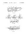
- FIG. 1is a diagrammatic representation of a multi-well assay plate structure according to a first embodiment of the present invention
- FIGS. 2 a to 2 cillustrate the steps involved in filling the wells of the container of FIG. 1 ;
- FIG. 2 dis an enlarged detail of part of the structure of FIGS. 2 a to 2 c;
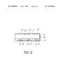
- FIG. 3shows a multi-well assay plate structure according to a second embodiment of the present invention
- FIG. 4 ashows a third embodiment of a disc-style structure for conducting multi-tests
- FIG. 4 bshows an enlarged cross-sectional detail of FIG. 4 a to allow snap-fitting of the plates in the disc sectors;
- FIG. 4 cis a fourth embodiment of a disc-style structure for conducting multi-tests
- FIG. 4 dshows a modification of the outer disc with hinged sectors and which is applicable to the previous embodiments
- FIG. 5depicts chemical/biochemical assay apparatus for conducting an assay on reactions carried out using the multi-well assay plate structures shown in FIG. 3 or FIGS. 4 a, b, c and d, and
- FIGS. 6 a and 6 bdepict the data and graphs respectively of antigen/antibody biochemical assays carried out using the apparatus of FIG. 5 on the assay plate shown in FIG. 4 a, b, c and d.
- FIG. 7shows a plate structure including digitally encoded address information.
- FIG. 8corresponds to FIG. 2 d with the location of lenses 90 shown.
- FIG. 1shows a multi-well assay plate, generally indicated by reference numeral 10 , having a box-like construction with a rectangular cross-section.
- the assay plate 10comprises an upper plate 12 , a lower plate 14 , and side and rear spacers 16 , 18 , 20 all of which are made of a transparent polycarbonate.
- the front of the box, indicated generally by the reference numeral 22is open to the surrounding space.
- the spacers 16 , 18 , 20are dimensioned to produce a space 21 of uniform spacing d between the opposed inner surfaces 12 a, 14 a of the upper and lower plates 12 , 12 .
- Spacing dis chosen such that a selected liquid is able to flow through the space 21 between the upper and lower plates 12 , 14 in a controlled manner by capillary or capillary-like action. Generally, d is less than 0.5 mm.
- a small opening 23extends through the upper plate 12 to communicate the inner space 21 with the exterior space surrounding the container. Opening 23 is located close to the rear wall 20 in order to prevent air-locks forming in the container during filling as will be described in more detail below.
- a regular array of wells or depressions 24are formed in the upper surface 14 a of the lower plate 14 .
- the polycarbonate assay plate with wells 24is produced by suitably moulding the lower plate 14 or by etching or pressing.
- the wells 24are 2 mm in diameter and 1 mm deep and typically have a volume of 5 ⁇ l and any suitable number of wells may be provided.
- the wellsare spaced 4 mm apart (centre or centre).
- FIGS. 2 a to 2 cillustrate the process by which the wells 24 of the assay plate 10 are filled with a liquid analyte 25 .
- the end 26 of a syringe 28 containing the liquid analyte 25is pressed into the opening 23 provided in the upper plate 12 of the container 10 ( FIG. 2 a ) so as to form an air-tight seal between the periphery of the syringe and the inner surface of the opening 23 .
- the plunger 30 of the syringe 28is then depressed to force the liquid 25 through the opening 23 into the space 21 within the plate 10 . As best seen in FIG.
- FIG. 2 dshows an enlarged cross-sectional view through part of the assay plate structure and showing how liquid is retained in wells 24 up to the meniscus.
- the wells 24 of the plate 10may be coated with an appropriate reactant.
- the wells 24are coated with an antigen.
- the remainder of the surface 14 ais coated with a blocking agent to prevent antigen and antibodies from binding to surface 14 a.
- FIG. 3a second embodiment of the present invention which depicts a multi-well assay plate in the form of a disk 32 designed for use with a rotating scanning device having a CD player type format.
- the disk 32 shown in FIG. 3comprises a pair of upper and lower circular plates 34 , 36 sandwiched together to provide a cylindrical space 38 therebetween. This space 38 is divided into eight sectors 40 by radially extending spacers 42 .
- a plurality of wells 44are provided in each sector 40 (one set of which is shown in broken outline) by forming the upper surface 36 a of the lower circular plate 36 as described with reference to FIG. 1 .
- the wells 44are of the same size and are spaced as for FIG. 1 .
- Each sector 40provides a chamber or space 46 which can be filled independently via openings 48 provided through the top surface of each sector 40 .
- the peripheral edge 50 of each sector 40is open to the surrounding space to provide a vent for the sector 40 to allow liquid to flow through the space or chamber 46 by displacing air therefrom.
- the upper and/or lower plates 34 , 36are made of transparent polycarbonate to enable a liquid beam to be scanned across the disk surface.
- the disk 32is provided with a central hole 52 to enable the disk 32 to be mounted on a rotatable shaft.
- one of the surfaces of the upper of lower plates 34 , 36may be provided with digitally encoded address information, as indicated at 39 in FIG. 7 , which can be read by the scanned light beam.
- This informationmay be encoded by way of “pits” and “lans” pressed or moulded into one of the plates. This address information can be used to provide accurate location information on the part of the disk which is being scanned by the light beam.
- FIG. 4a third embodiment of a disk assay plate 54 which comprises upper and lower circular transparent polycarbonate plates 56 , 58 which are spaced apart by a number of radially extending spacer walls 60 to create a plurality of disk sectors 62 .
- the inner surfaces 56 a, 58 a of the circular plates 56 , 58are both planar.
- Each disk sector 62is arranged to receive a sector plate insert 64 which is a transparent polycarbonate plate with a detachable handle 66 on the outer side to facilitate entry and removal of the plate insert 64 in the sector 62 .
- the plate insert 64 and spacer wall 60have respective recesses/projections (not shown in the interest of clarity) which allow the plate insert 64 to be inserted only in the correct orientation.
- the plate insert 64has a groove 68 , as shown in FIG. 4 b for example, which allows the inset to be snap-fitted over a projection 70 upstanding from plate 58 into the sector.
- the thickness of the sector plate insert 64is marginally less than the spacing provided between the upper and lower plates 56 , 58 so that the plate insert 64 can be pressed/fitted into one of the disk sector 62 to define a liquid receiving chamber or space 73 between the upper surface 64 a of the plate insert 64 and the lower surface 56 a of the upper disk plate 56 .
- Openings 72are provided through the upper disk plate 56 into each disk sector 64 whilst the space 70 between the radially outermost peripheral edge 74 of the insert plate 64 and the upper plate 56 provides a further vent or filling opening into the disk sector 62 .
- the surface 64 a of the insert plate 64is provided with a plurality of wells 76 as described with respect to FIG. 1 .
- the wellsare 2 mm in diameter, 1 mm in depth and 4 mm apart (spaced between centres). These wells are filled by introducing liquid into the disk sector 64 through the upper opening 72 to fill space 70 and subsequently withdrawing the liquid through the same opening as previously described.
- FIG. 5 of the drawingsdepicts assay apparatus for conducting an assay on reactions carried out using the assay plate structures of the already described embodiments.
- the assay apparatuswill be described in combination with the preferred embodiment shown in FIGS. 4 a,b with like numerals referring to like parts.
- the apparatusincludes a suitable automatic fluid filling/withdrawal system, generally indicated by reference numeral 80 , which operates a syringe 82 to dispense/retrieve fluid from a reservoir 84 via the openings 72 into the space 70 between the plate surface 56 a and the surface 64 a of each sector plate 64 .
- the fluidcan of course be dispensed and retained manually if desired. This is achieved for each sector by rotating the disk plate 54 to a suitable position to allow fluid filling/withdrawal.
- the platesare pre-prepared with various reagents, e.g.
- antigensare inserted in the appropriate wells 76 , as described with reference to FIGS. 4 a, 4 b.
- the platesare first flooded with fluid carrying antibodies and withdrawal of the fluid leaves the antibody/antigen reagents filling the wells 76 resulting in a reaction.
- the disk sector plate 54is more suitable for conducting a variety of different assays, e.g. antigen/antibody assays for different patients, i.e. one patient/sector.
- the opening through which a liquid analyte is introducedmay be provided through the lower plate of the multi-well container. More than one opening can be used for faster flooding. This opening may be arranged to receive the tip of a syringe needle.
- the vent openingmay also be provided in any one of the walls of the container although it is preferably provided in a peripheral wall.
- the opening 22may be provided by a single opening 22 or by a series of openings or vents as shown in FIG. 4 d for example.
- a lasermay be used with CD optics instead of the microscope and video camera for the embodiment of FIG. 4 .
- the upper plant surface 56can have sector covers connected to a lower surface or central boss by a hinge, for example integrated living hinge 90 at the inner radius to allow each disk sector 62 to be pivotally raised and lowered and allow sector plates 64 to be inserted into each sector.
- the well size and spacingmay be varied as required, for example the wells could be 3 mm in diameter; 1.5 mm apart and spaced 5.5 mm between centre. The exact size and spacing is a matter of choice consistent with the requirement that fluid is retained in the wells after withdrawal as described above.
- the wellscould also be filled during flooding of the space depending on the well size, type of plastic and fluid properties. However, liquid will still be retained in the wells upon withdrawal of the liquid.
- the structure and inserts mademay be of any suitable optical transmissive plastic, such as polystyrene or perspexTM.
- the handle 66may be integrated with or detachable from plate 64 . As shown in FIG. 4 a the radially extending ribs may have radial shoulders 92 to define a recess 94 for receiving the plate 64 also defining the spacing height between the surface 64 a of the plate 64 and the underside 56 a for receiving the liquid. Suitable materials may be used to coat the interior of the sectors to aid fluid movement as described with reference to silicone above.
- Suitable materialsmay be used to increase the hydrophobicity of liquid across the sector and hydrophilicity to the movement of liquid into the desired location, e.g. wells.
- the wellsmay be coated by a suitable optical reflective material to enhance the reflection of light and observation of reactions occurring within the wells and, similarly, lenses 90 may be located in the top or bottom light transmissive plates 12 and 14 as seen in FIG. 8 , to improve optical assessment of the reaction.
- These lensesmay be mounded into the upper or lower plates of the exemplary embodiments during the manufacture as is well known in plastic moulding processes. Separate optical elements may be used instead, if appropriate.
- the wellsare absent from the upper surface of the plate and that plate retains its planar surface to enable a thin, uniform layer of liquid to be introduced into the space between the upper disk plate and the insert plate.
- An insoluble substrate with reagent or reagentse.g. an antigen
- each insertmay be provided with a lid which can be slid into the space between the insert and the upper plate 22 of the disk following filling of the wells.
- the lower surface of the lidmay be arrange to be flush with the surface of the insert so as to close off each well. This prevents liquid from being thrown out of the wells during spinning of the disk during automated reading and analysis.
- the inventionhas use in immunoassay applications including tests for sexually transmitted diseases, parasites, allergens, cancer markers and cardiac markers, either in laboratories or at point-of-care locations, for example medical practitioners offices or the like.
- Other applications of the inventionare in chemical and biochemical assays. Examples of such assays include immunoassay, clinical biochemistry tests, nucleic acid analysis and receptor ligand interactions.
- Immunoassay applicationinclude tests designed to detect infections organisms, viruses, parasites as well as endogenous analytes such as circulating hormone levels and cancer markers.
- Examples of chemical analysisinclude measure of phosphate and nitrate levels in water, environmental and industrial monitoring including potable and waste water and process monitoring. The system could be used in a variety of settings including clinical laboratories, doctor's and veterinary surgeries as well as industrial and research laboratories.
Landscapes
- Health & Medical Sciences (AREA)
- Chemical & Material Sciences (AREA)
- Hematology (AREA)
- Immunology (AREA)
- Life Sciences & Earth Sciences (AREA)
- Engineering & Computer Science (AREA)
- Analytical Chemistry (AREA)
- General Health & Medical Sciences (AREA)
- Chemical Kinetics & Catalysis (AREA)
- Molecular Biology (AREA)
- Clinical Laboratory Science (AREA)
- Biomedical Technology (AREA)
- Urology & Nephrology (AREA)
- Physics & Mathematics (AREA)
- General Physics & Mathematics (AREA)
- Cell Biology (AREA)
- Food Science & Technology (AREA)
- Medicinal Chemistry (AREA)
- Biotechnology (AREA)
- Biochemistry (AREA)
- Microbiology (AREA)
- Pathology (AREA)
- Automatic Analysis And Handling Materials Therefor (AREA)
- Optical Measuring Cells (AREA)
- Analysing Materials By The Use Of Radiation (AREA)
- Apparatus Associated With Microorganisms And Enzymes (AREA)
- Sampling And Sample Adjustment (AREA)
- Radar Systems Or Details Thereof (AREA)
- Investigating Or Analysing Biological Materials (AREA)
Abstract
Description
- a first upper surface,
- a second lower surface having a plurality of wells disposed therein,
- the first and second surfaces defining a chamber having an inlet and an outlet, the inlet and outlet allowing fluid to be introduced and withdrawn from the chamber, the wells being proportioned and dimensioned to retain a volume of fluid in each well following withdrawal of the liquid.
- 1. The underside of upper surface (56a) of is coated with silicone spray to aid fluid movement.
Sector plates 64 are also coated includingwells 76. Any excess silicone is removed. - 2.
Sectors wells 76 are loaded by hand with a panel of seven antigens—Human Serum Albumin, Antitrypsin, Macroglobulin, Antithrombin III, Catalase, Antichymotrypsin and Plasminogen at a concentration of 20 ug/ml in PBS and a volume of 2 ul/well. Control wells contain PBS only. Antigens can be arranged in blocks of the same on thesector plate 64 in a series giving a panel of tests evenly distributed over the sector. Incubate at room temperature for 15 minutes. - 3. Wash with 0.05% PBS-Tween using flood/fill technique—1 ml is flooded across the sector plate via
holes 72 in the top plate using a 1 ml pipette. This pipetted up and down three times then withdrawn and the washing discarded. This repeated a further three times to ensure complete washing. - 4. Blocking is carried out to prevent reactions occurring other than at well sites with 50 mg/ml Bovine Serum Albumin (BSA) (in PBS) using flood/fill. 1 ml of BSA/PBS is flooded across the sector, pipetted up and down three times, withdrawn and discarded. This allows all
wells 76 to be filled simultaneously. Incubate for 15 minutes at room temperature. - 5. Wash as before.
- 6. Primary antibodies are applied to the
sector plate 64 as a mixture using flood/fill with each individual antibody at the following concentrations:anti-Human Serum Albumin 1/1000,anti-Antitrypsin 1/2000,anti-Macroglobulin 1/2000,anti-Antithrombin III 1/1000, anti-Catalase 1,1000,anti-Antichymotrypsin 1/1000,anti-Plasminogen 1/1000. Antibodies are diluted in 0.5 mg/ml BSA/PBS. Incubate for 10 minutes at room temperature. - 7. Wash as before.
- 8. Second antibody is Amdex anti-IgG (peroxidase conjugate) at a concentration of 1/1000 in 0.5 mg/ml BSA/PGS. After washing this is applied to the sector using flood/fill. Incubate at room temperature for 10 minutes.
- 9. Wash as before.
- 10. The substrate is insoluble Tetramethylbenzidine (TMB). This reacts with the peroxidase on the second antibody to produce an intense blue colour. After washing this is applied to the
sector plate 64 by flood/fill but is left flooded across thesector plate 64 after pipetting up and down several times. Incubate for 10 minutes at room temperature. - 11. Remove TMB and discard. Wash out the wells with distilled water four times by flood/fill. A blue precipitate will be evident in wells with a positive reaction. No colour is produced in negative wells. Store sections in dark as TMB will slowly fade in daylight. The date for the above assay is shown in
FIG. 6 aand is graphically represented inFIG. 6 bwhich is reproducible and is representative of a large number of experiments (712).
Claims (39)
Priority Applications (1)
| Application Number | Priority Date | Filing Date | Title |
|---|---|---|---|
| US12/140,691US20090068064A1 (en) | 1996-08-10 | 2008-06-17 | Apparatus and method for conducting assays |
Applications Claiming Priority (2)
| Application Number | Priority Date | Filing Date | Title |
|---|---|---|---|
| GBGB9620934.1AGB9620934D0 (en) | 1996-10-08 | 1996-10-08 | Multi-well containers |
| PCT/GB1997/002708WO1998015356A1 (en) | 1996-10-08 | 1997-10-08 | Apparatus and method for conducting assays |
Publications (1)
| Publication Number | Publication Date |
|---|---|
| US7387898B1true US7387898B1 (en) | 2008-06-17 |
Family
ID=10801090
Family Applications (2)
| Application Number | Title | Priority Date | Filing Date |
|---|---|---|---|
| US09/284,421Expired - Fee RelatedUS7387898B1 (en) | 1996-08-10 | 1997-10-08 | Apparatus and method for conducting assays |
| US12/140,691AbandonedUS20090068064A1 (en) | 1996-08-10 | 2008-06-17 | Apparatus and method for conducting assays |
Family Applications After (1)
| Application Number | Title | Priority Date | Filing Date |
|---|---|---|---|
| US12/140,691AbandonedUS20090068064A1 (en) | 1996-08-10 | 2008-06-17 | Apparatus and method for conducting assays |
Country Status (10)
| Country | Link |
|---|---|
| US (2) | US7387898B1 (en) |
| EP (2) | EP0938382B1 (en) |
| CN (1) | CN1108874C (en) |
| AT (1) | ATE234154T1 (en) |
| AU (1) | AU724660B2 (en) |
| DE (1) | DE69719782T2 (en) |
| GB (1) | GB9620934D0 (en) |
| IL (1) | IL130042A0 (en) |
| NZ (1) | NZ335863A (en) |
| WO (1) | WO1998015356A1 (en) |
Cited By (17)
| Publication number | Priority date | Publication date | Assignee | Title |
|---|---|---|---|---|
| US20050202733A1 (en)* | 2004-03-09 | 2005-09-15 | Brother Kogyo Kabushiki Kaisha | Test object receptacle, test apparatus, and test method |
| US20070297946A1 (en)* | 2003-08-12 | 2007-12-27 | Sellers James M | Slide cartridge and reagent test slides for use with a chemical analyzer, and chemical analyzer for same |
| US20080102527A1 (en)* | 1998-05-01 | 2008-05-01 | Gen-Probe Incorporated | Method for Introducing A Fluid Into A Reaction Receptacle Contained Within A Temperature-Controlled Environment |
| US20090068064A1 (en)* | 1996-08-10 | 2009-03-12 | John Francis Gordon | Apparatus and method for conducting assays |
| US8318500B2 (en) | 1998-05-01 | 2012-11-27 | Gen-Probe, Incorporated | Method for agitating the contents of a reaction receptacle within a temperature-controlled environment |
| US20140087958A1 (en)* | 2012-09-26 | 2014-03-27 | Cepheid | Honeycomb tube |
| US10820847B1 (en) | 2019-08-15 | 2020-11-03 | Talis Biomedical Corporation | Diagnostic system |
| US11609413B2 (en)* | 2017-11-14 | 2023-03-21 | S.D. Sight Diagnostics Ltd. | Sample carrier for microscopy and optical density measurements |
| US11733150B2 (en) | 2016-03-30 | 2023-08-22 | S.D. Sight Diagnostics Ltd. | Distinguishing between blood sample components |
| US11796788B2 (en) | 2015-09-17 | 2023-10-24 | S.D. Sight Diagnostics Ltd. | Detecting a defect within a bodily sample |
| US11808758B2 (en) | 2016-05-11 | 2023-11-07 | S.D. Sight Diagnostics Ltd. | Sample carrier for optical measurements |
| WO2024211906A1 (en)* | 2023-04-06 | 2024-10-10 | University Of Florida Research Foundation, Incorporated | Multi-well plates and methods of use |
| US12174175B2 (en) | 2016-05-11 | 2024-12-24 | S.D. Sight Diagnostics Ltd. | Performing measurements on a sample |
| US12189112B2 (en) | 2019-12-12 | 2025-01-07 | S.D. Sight Diagnostics Ltd. | Artificial generation of color blood smear image |
| WO2025096875A1 (en)* | 2023-11-03 | 2025-05-08 | Generate Biomedicines, Inc. | High-throughput electrochemical sensing device, system, and related methods |
| US12393010B2 (en) | 2013-08-26 | 2025-08-19 | S.D. Sight Diagnostics Ltd. | Distinguishing between entities in a blood sample |
| US12436101B2 (en) | 2019-12-12 | 2025-10-07 | S.D. Sight Diagnostics Ltd. | Microscopy unit |
Families Citing this family (37)
| Publication number | Priority date | Publication date | Assignee | Title |
|---|---|---|---|---|
| GB9418981D0 (en) | 1994-09-21 | 1994-11-09 | Univ Glasgow | Apparatus and method for carrying out analysis of samples |
| US6327031B1 (en) | 1998-09-18 | 2001-12-04 | Burstein Technologies, Inc. | Apparatus and semi-reflective optical system for carrying out analysis of samples |
| US6342349B1 (en) | 1996-07-08 | 2002-01-29 | Burstein Technologies, Inc. | Optical disk-based assay devices and methods |
| IL136978A0 (en)* | 1997-12-30 | 2001-06-14 | Remacle Jose | Method comprising capture molecule fixed on disc surface |
| GB9809943D0 (en)* | 1998-05-08 | 1998-07-08 | Amersham Pharm Biotech Ab | Microfluidic device |
| US6888951B1 (en) | 1999-08-23 | 2005-05-03 | Nagaoka & Co., Ltd. | Methods and apparatus for analyzing operational and analyte data acquired from optical disc |
| US6272939B1 (en)* | 1999-10-15 | 2001-08-14 | Applera Corporation | System and method for filling a substrate with a liquid sample |
| EP1369699A1 (en)* | 1999-10-15 | 2003-12-10 | PE Corporation (NY) | System and method for filling a substrate with a liquid sample |
| US7054258B2 (en) | 2000-12-08 | 2006-05-30 | Nagaoka & Co., Ltd. | Optical disc assemblies for performing assays |
| US6760298B2 (en) | 2000-12-08 | 2004-07-06 | Nagaoka & Co., Ltd. | Multiple data layer optical discs for detecting analytes |
| US7079468B2 (en) | 2000-12-08 | 2006-07-18 | Burstein Technologies, Inc. | Optical discs for measuring analytes |
| AU2002239552A1 (en)* | 2000-12-08 | 2002-06-18 | Burstein Technologies, Inc. | Multiple data layer optical discs for detecting analytes |
| US7157047B2 (en)* | 2001-02-09 | 2007-01-02 | Pss Bio Instruments, Inc. | Device for containing, reacting and measuring, and method of containing, reacting and measuring |
| NL1017374C2 (en)* | 2001-02-15 | 2002-08-16 | Univ Delft Tech | Device for carrying out a reaction, as well as a method for carrying out a reaction in the device. |
| CA2441206A1 (en) | 2001-03-19 | 2002-09-26 | Gyros Ab | Characterization of reaction variables |
| ATE342498T1 (en)* | 2001-07-19 | 2006-11-15 | Burstein Technologies Inc | TRANSMISSIVE OPTICAL PLATE FOR PHYSICAL MEASUREMENTS |
| DE10262157B4 (en)* | 2002-02-01 | 2006-11-09 | Fraunhofer-Gesellschaft zur Förderung der angewandten Forschung e.V. | Plate for use in cryogenic storage of biological specimens has wells, into which specimens are placed, fits into cover in same way as drawer of matchbox, and is held in position by e.g. studs and recesses |
| DE10262208B4 (en)* | 2002-02-01 | 2008-04-03 | Fraunhofer-Gesellschaft zur Förderung der angewandten Forschung e.V. | Sample carrier for a variety of cryoprobes |
| US7785782B2 (en) | 2002-12-12 | 2010-08-31 | Novartis Vaccines And Diagnostics, Inc. | Device and method for in-line blood testing using biochips |
| IL154677A0 (en) | 2003-02-27 | 2003-09-17 | Univ Bar Ilan | A method and apparatus for manipulating an individual cell |
| JP2007502428A (en) | 2003-05-23 | 2007-02-08 | ユィロス・パテント・アクチボラグ | Fluid function based on non-wetting surface |
| US9200245B2 (en) | 2003-06-26 | 2015-12-01 | Seng Enterprises Ltd. | Multiwell plate |
| US7888110B2 (en) | 2003-06-26 | 2011-02-15 | Seng Enterprises Ltd. | Pico liter well holding device and method of making the same |
| US7544805B2 (en) | 2004-02-03 | 2009-06-09 | Chemagis Ltd. | Stable amorphous forms of montelukast sodium |
| US7403647B2 (en) | 2004-09-13 | 2008-07-22 | Seng Enterprises Ltd. | Method for identifying an image of a well in an image of a well-bearing component |
| WO2006003664A1 (en)* | 2004-07-07 | 2006-01-12 | Seng Enterprises Ltd. | Method and device for identifying an image of a well in an image of a well-bearing component |
| DE202006012937U1 (en)* | 2006-08-23 | 2007-12-27 | LÖRSCH, Johannes | Holding device for samples to be examined, in particular chemical or biological substances or the like. |
| US9145540B1 (en) | 2007-11-15 | 2015-09-29 | Seng Enterprises Ltd. | Device for the study of living cells |
| EP2237887A2 (en) | 2007-12-26 | 2010-10-13 | Seng Enterprises Ltd. | Device for the study of living cells |
| US8446463B2 (en)* | 2008-08-22 | 2013-05-21 | Genprime, Inc. | Apparatus, method and article to perform assays using assay strips |
| AT508708B1 (en)* | 2009-10-22 | 2011-06-15 | Gerhard Bonecker | TEST SET FOR A PHOTOMETRIC MEASURING DEVICE AND PHOTOMETRIC MEASURING METHOD FOR A SAMPLE LIQUID |
| WO2012063647A1 (en) | 2010-11-08 | 2012-05-18 | 株式会社日立ハイテクノロジーズ | Reaction plate assembly, reaction plate and nucleic acid analysis device |
| CN109781630A (en) | 2013-01-04 | 2019-05-21 | 梅索磅秤技术有限公司 | Assay device, method and reagent |
| US11090654B2 (en) | 2014-02-18 | 2021-08-17 | Drugarray, Inc. | Multi-well separation apparatus and reagent delivery device |
| DE102014019526B4 (en)* | 2014-12-23 | 2016-10-27 | Testo Ag | Examination procedure, disk-shaped sample carrier and use of a sample carrier |
| US10576475B2 (en) | 2016-09-15 | 2020-03-03 | Genprime, Inc. | Diagnostic assay strip cassette |
| JP2024077768A (en)* | 2022-11-29 | 2024-06-10 | 博訊生物科技股▲分▼有限公司 | Automatic cell freezing and thawing equipment and rack carrier used therein |
Citations (26)
| Publication number | Priority date | Publication date | Assignee | Title |
|---|---|---|---|---|
| GB1557984A (en) | 1975-09-29 | 1979-12-19 | Lilja J E | Capillary sampling optical cuvette |
| US4483925A (en)* | 1982-12-30 | 1984-11-20 | Becton, Dickinson And Company | Liquid removal device |
| GB2147100A (en) | 1983-08-05 | 1985-05-01 | Orbec Ltd | Multi-well plate inoculating means |
| US4596695A (en) | 1984-09-10 | 1986-06-24 | Cottingham Hugh V | Agglutinographic reaction chamber |
| US4722598A (en)* | 1986-12-04 | 1988-02-02 | Max M. Ford | Diagnostic microscope slide having multiple sample wells and cover |
| US4900513A (en)* | 1986-07-11 | 1990-02-13 | Beckman Instruments, Inc. | Sample loading apparatus |
| US4961906A (en)* | 1984-04-12 | 1990-10-09 | Fisher Scientific Company | Liquid handling |
| EP0417305A1 (en)* | 1989-03-07 | 1991-03-20 | Idemitsu Petrochemical Co. Ltd. | Analyzer of liquid sample and analyzing method of liquid sample using said analyzer |
| EP0435246A2 (en) | 1989-12-27 | 1991-07-03 | Olympus Optical Co., Ltd. | Reaction vessel |
| US5041266A (en)* | 1989-12-21 | 1991-08-20 | Hoffmann-La Roche Inc. | Tray for immunometric determinations |
| US5167922A (en)* | 1990-04-27 | 1992-12-01 | Pb Diagnostic Systems Inc. | Assay cartridge |
| US5310523A (en)* | 1990-06-15 | 1994-05-10 | Chiron Corporation | Self-contained assay assembly and apparatus |
| WO1994029484A1 (en) | 1993-06-09 | 1994-12-22 | Gamera Bioscience Corporation | Magnetic cycle reaction |
| WO1995025815A1 (en) | 1994-03-24 | 1995-09-28 | Gamera Bioscience Corporation | A dna meltometer and methods of use thereof |
| US5496520A (en)* | 1982-01-08 | 1996-03-05 | Kelton; Arden A. | Rotary fluid manipulator |
| WO1996009548A1 (en)* | 1994-09-21 | 1996-03-28 | The University Court Of The University Of Glasgow | Apparatus and method for carrying out analysis of samples |
| WO1996017959A2 (en) | 1994-12-09 | 1996-06-13 | Gamera Bioscience Corporation | An apparatus for performing magnetic cycle reaction |
| US5585069A (en)* | 1994-11-10 | 1996-12-17 | David Sarnoff Research Center, Inc. | Partitioned microelectronic and fluidic device array for clinical diagnostics and chemical synthesis |
| WO1997021090A1 (en) | 1995-12-05 | 1997-06-12 | Gamera Bioscience | Devices and methods for using centripetal acceleration to drive fluid movement in a microfluidics system with on-board informatics |
| US5700655A (en)* | 1995-11-14 | 1997-12-23 | Idexx Laboratories, Inc. | Method for quantification of biological material in a sample |
| US5792654A (en)* | 1997-05-12 | 1998-08-11 | Neogen Corporation | Microorganism culture tray |
| US5955352A (en)* | 1994-12-22 | 1999-09-21 | Showa Yakuhin Kako Co., Ltd. | Instruments for chemical and microbiological tests |
| US6027873A (en)* | 1999-03-19 | 2000-02-22 | Genencor International, Inc. | Multi-through hole testing plate for high throughput screening |
| US6027695A (en)* | 1998-04-01 | 2000-02-22 | Dupont Pharmaceuticals Company | Apparatus for holding small volumes of liquids |
| US6143496A (en)* | 1997-04-17 | 2000-11-07 | Cytonix Corporation | Method of sampling, amplifying and quantifying segment of nucleic acid, polymerase chain reaction assembly having nanoliter-sized sample chambers, and method of filling assembly |
| US6268209B1 (en)* | 1997-10-27 | 2001-07-31 | Idexx Laboratories, Inc. | Device and method for determination of analyte in a solution |
Family Cites Families (11)
| Publication number | Priority date | Publication date | Assignee | Title |
|---|---|---|---|---|
| GB1572596A (en)* | 1976-12-06 | 1980-07-30 | Opto Electronic Displays Ltd | Apparatus and method for innoculation |
| US4077845A (en)* | 1977-04-20 | 1978-03-07 | Miles Laboratories, Inc. | Disposable inoculation device and process of using same |
| US4195060A (en)* | 1978-02-08 | 1980-03-25 | Abbott Laboratories | Liquid reagent cartridge cuvette |
| US5084397A (en)* | 1988-04-11 | 1992-01-28 | Miles Inc. | Method and apparatus for controlled reagent deposition in reaction cassettes and the like |
| US5281540A (en)* | 1988-08-02 | 1994-01-25 | Abbott Laboratories | Test array for performing assays |
| AU642444B2 (en)* | 1989-11-30 | 1993-10-21 | Mochida Pharmaceutical Co., Ltd. | Reaction vessel |
| US5182082A (en)* | 1991-01-23 | 1993-01-26 | Becton, Dickinson And Company | Multiple aliquot device for distributing a liquid solution into a well |
| JP3193443B2 (en)* | 1992-04-24 | 2001-07-30 | オリンパス光学工業株式会社 | Automatic analyzer |
| JPH07113872A (en)* | 1993-10-13 | 1995-05-02 | Shigeo Baba | Method and apparatus for measuring beta emitter |
| CH687592A5 (en)* | 1993-10-18 | 1997-01-15 | Eidgenoess Munitionsfab Thun | Mehrgefaessanordnung for instrumental analysis. |
| GB9620934D0 (en)* | 1996-10-08 | 1996-11-27 | Molecular Drives Limited | Multi-well containers |
- 1996
- 1996-10-08GBGBGB9620934.1Apatent/GB9620934D0/enactivePending
- 1997
- 1997-10-08USUS09/284,421patent/US7387898B1/ennot_activeExpired - Fee Related
- 1997-10-08CNCN97180429Apatent/CN1108874C/ennot_activeExpired - Fee Related
- 1997-10-08WOPCT/GB1997/002708patent/WO1998015356A1/ennot_activeApplication Discontinuation
- 1997-10-08ILIL13004297Apatent/IL130042A0/enunknown
- 1997-10-08EPEP97943992Apatent/EP0938382B1/ennot_activeExpired - Lifetime
- 1997-10-08ATAT97943992Tpatent/ATE234154T1/ennot_activeIP Right Cessation
- 1997-10-08EPEP01123697Apatent/EP1188482A3/ennot_activeWithdrawn
- 1997-10-08NZNZ335863Apatent/NZ335863A/enunknown
- 1997-10-08AUAU45642/97Apatent/AU724660B2/ennot_activeCeased
- 1997-10-08DEDE69719782Tpatent/DE69719782T2/ennot_activeExpired - Fee Related
- 2008
- 2008-06-17USUS12/140,691patent/US20090068064A1/ennot_activeAbandoned
Patent Citations (27)
| Publication number | Priority date | Publication date | Assignee | Title |
|---|---|---|---|---|
| GB1557984A (en) | 1975-09-29 | 1979-12-19 | Lilja J E | Capillary sampling optical cuvette |
| US5496520A (en)* | 1982-01-08 | 1996-03-05 | Kelton; Arden A. | Rotary fluid manipulator |
| US4483925A (en)* | 1982-12-30 | 1984-11-20 | Becton, Dickinson And Company | Liquid removal device |
| GB2147100A (en) | 1983-08-05 | 1985-05-01 | Orbec Ltd | Multi-well plate inoculating means |
| US4961906A (en)* | 1984-04-12 | 1990-10-09 | Fisher Scientific Company | Liquid handling |
| US4596695A (en) | 1984-09-10 | 1986-06-24 | Cottingham Hugh V | Agglutinographic reaction chamber |
| US4900513A (en)* | 1986-07-11 | 1990-02-13 | Beckman Instruments, Inc. | Sample loading apparatus |
| US4722598A (en)* | 1986-12-04 | 1988-02-02 | Max M. Ford | Diagnostic microscope slide having multiple sample wells and cover |
| EP0417305A1 (en)* | 1989-03-07 | 1991-03-20 | Idemitsu Petrochemical Co. Ltd. | Analyzer of liquid sample and analyzing method of liquid sample using said analyzer |
| US5041266A (en)* | 1989-12-21 | 1991-08-20 | Hoffmann-La Roche Inc. | Tray for immunometric determinations |
| EP0435246A2 (en) | 1989-12-27 | 1991-07-03 | Olympus Optical Co., Ltd. | Reaction vessel |
| US5167922A (en)* | 1990-04-27 | 1992-12-01 | Pb Diagnostic Systems Inc. | Assay cartridge |
| US5310523A (en)* | 1990-06-15 | 1994-05-10 | Chiron Corporation | Self-contained assay assembly and apparatus |
| WO1994029484A1 (en) | 1993-06-09 | 1994-12-22 | Gamera Bioscience Corporation | Magnetic cycle reaction |
| US5545540A (en) | 1993-06-09 | 1996-08-13 | Gamera Bioscience Corporation | Isothermal, magnetic particle-mediated acid amplification |
| WO1995025815A1 (en) | 1994-03-24 | 1995-09-28 | Gamera Bioscience Corporation | A dna meltometer and methods of use thereof |
| WO1996009548A1 (en)* | 1994-09-21 | 1996-03-28 | The University Court Of The University Of Glasgow | Apparatus and method for carrying out analysis of samples |
| US5585069A (en)* | 1994-11-10 | 1996-12-17 | David Sarnoff Research Center, Inc. | Partitioned microelectronic and fluidic device array for clinical diagnostics and chemical synthesis |
| WO1996017959A2 (en) | 1994-12-09 | 1996-06-13 | Gamera Bioscience Corporation | An apparatus for performing magnetic cycle reaction |
| US5955352A (en)* | 1994-12-22 | 1999-09-21 | Showa Yakuhin Kako Co., Ltd. | Instruments for chemical and microbiological tests |
| US5700655A (en)* | 1995-11-14 | 1997-12-23 | Idexx Laboratories, Inc. | Method for quantification of biological material in a sample |
| WO1997021090A1 (en) | 1995-12-05 | 1997-06-12 | Gamera Bioscience | Devices and methods for using centripetal acceleration to drive fluid movement in a microfluidics system with on-board informatics |
| US6143496A (en)* | 1997-04-17 | 2000-11-07 | Cytonix Corporation | Method of sampling, amplifying and quantifying segment of nucleic acid, polymerase chain reaction assembly having nanoliter-sized sample chambers, and method of filling assembly |
| US5792654A (en)* | 1997-05-12 | 1998-08-11 | Neogen Corporation | Microorganism culture tray |
| US6268209B1 (en)* | 1997-10-27 | 2001-07-31 | Idexx Laboratories, Inc. | Device and method for determination of analyte in a solution |
| US6027695A (en)* | 1998-04-01 | 2000-02-22 | Dupont Pharmaceuticals Company | Apparatus for holding small volumes of liquids |
| US6027873A (en)* | 1999-03-19 | 2000-02-22 | Genencor International, Inc. | Multi-through hole testing plate for high throughput screening |
Cited By (42)
| Publication number | Priority date | Publication date | Assignee | Title |
|---|---|---|---|---|
| US20090068064A1 (en)* | 1996-08-10 | 2009-03-12 | John Francis Gordon | Apparatus and method for conducting assays |
| US8709814B2 (en) | 1998-05-01 | 2014-04-29 | Gen-Probe Incorporated | Method for incubating the contents of a receptacle |
| US20080102527A1 (en)* | 1998-05-01 | 2008-05-01 | Gen-Probe Incorporated | Method for Introducing A Fluid Into A Reaction Receptacle Contained Within A Temperature-Controlled Environment |
| US8192992B2 (en) | 1998-05-01 | 2012-06-05 | Gen-Probe Incorporated | System and method for incubating the contents of a reaction receptacle |
| US8221682B2 (en) | 1998-05-01 | 2012-07-17 | Gen-Probe Incorporated | System for incubating the contents of a reaction receptacle |
| US8309358B2 (en)* | 1998-05-01 | 2012-11-13 | Gen-Probe Incorporated | Method for introducing a fluid into a reaction receptacle contained within a temperature-controlled environment |
| US8318500B2 (en) | 1998-05-01 | 2012-11-27 | Gen-Probe, Incorporated | Method for agitating the contents of a reaction receptacle within a temperature-controlled environment |
| US8337753B2 (en) | 1998-05-01 | 2012-12-25 | Gen-Probe Incorporated | Temperature-controlled incubator having a receptacle mixing mechanism |
| US20070297946A1 (en)* | 2003-08-12 | 2007-12-27 | Sellers James M | Slide cartridge and reagent test slides for use with a chemical analyzer, and chemical analyzer for same |
| US8287823B2 (en)* | 2003-08-12 | 2012-10-16 | Idexx Laboratories, Inc. | Slide cartridge and reagent test slides for use with a chemical analyzer, and chemical analyzer for same |
| US7790468B2 (en)* | 2004-03-09 | 2010-09-07 | Brother Kogyo Kabushiki Kaisha | Test object receptacle, test apparatus, and test method |
| US20050202733A1 (en)* | 2004-03-09 | 2005-09-15 | Brother Kogyo Kabushiki Kaisha | Test object receptacle, test apparatus, and test method |
| US9914968B2 (en)* | 2012-09-26 | 2018-03-13 | Cepheid | Honeycomb tube |
| US11795506B2 (en) | 2012-09-26 | 2023-10-24 | Cepheid | Honeycomb tube |
| US20150275292A1 (en)* | 2012-09-26 | 2015-10-01 | Cepheid | Honeycomb tube |
| US10190165B2 (en)* | 2012-09-26 | 2019-01-29 | Cepheid | Honeycomb tube |
| US10767226B2 (en) | 2012-09-26 | 2020-09-08 | Cepheid | Honeycomb tube |
| US11739383B2 (en) | 2012-09-26 | 2023-08-29 | Cepheid | Honeycomb tube |
| US10870884B2 (en) | 2012-09-26 | 2020-12-22 | Cepheid | Honeycomb tube |
| US12281358B2 (en) | 2012-09-26 | 2025-04-22 | Cepheid | Honeycomb tube |
| US20140087958A1 (en)* | 2012-09-26 | 2014-03-27 | Cepheid | Honeycomb tube |
| US12203135B2 (en) | 2012-09-26 | 2025-01-21 | Cepheid | Honeycomb tube |
| US12393010B2 (en) | 2013-08-26 | 2025-08-19 | S.D. Sight Diagnostics Ltd. | Distinguishing between entities in a blood sample |
| US11796788B2 (en) | 2015-09-17 | 2023-10-24 | S.D. Sight Diagnostics Ltd. | Detecting a defect within a bodily sample |
| US11914133B2 (en) | 2015-09-17 | 2024-02-27 | S.D. Sight Diagnostics Ltd. | Methods and apparatus for analyzing a bodily sample |
| US11733150B2 (en) | 2016-03-30 | 2023-08-22 | S.D. Sight Diagnostics Ltd. | Distinguishing between blood sample components |
| US12196664B2 (en) | 2016-03-30 | 2025-01-14 | S.D. Sight Diagnostics Ltd. | Distinguishing between blood sample components |
| US12174175B2 (en) | 2016-05-11 | 2024-12-24 | S.D. Sight Diagnostics Ltd. | Performing measurements on a sample |
| US11808758B2 (en) | 2016-05-11 | 2023-11-07 | S.D. Sight Diagnostics Ltd. | Sample carrier for optical measurements |
| US12181463B2 (en) | 2016-05-11 | 2024-12-31 | S.D. Sight Diagnostics Ltd. | Performing optical measurements on a sample |
| US11609413B2 (en)* | 2017-11-14 | 2023-03-21 | S.D. Sight Diagnostics Ltd. | Sample carrier for microscopy and optical density measurements |
| US12196940B2 (en) | 2017-11-14 | 2025-01-14 | S.D. Sight Diagnostics Ltd. | Sample carrier for microscopy and optical density measurements |
| US11921272B2 (en) | 2017-11-14 | 2024-03-05 | S.D. Sight Diagnostics Ltd. | Sample carrier for optical measurements |
| US11614609B2 (en)* | 2017-11-14 | 2023-03-28 | S.D. Sight Diagnostics Ltd. | Sample carrier for microscopy measurements |
| US11986299B2 (en) | 2019-08-15 | 2024-05-21 | Talis Biomedical Corporation | Diagnostic system |
| US11008627B2 (en) | 2019-08-15 | 2021-05-18 | Talis Biomedical Corporation | Diagnostic system |
| US12310730B2 (en) | 2019-08-15 | 2025-05-27 | Talis Biomedical Corporation | Diagnostic system |
| US10820847B1 (en) | 2019-08-15 | 2020-11-03 | Talis Biomedical Corporation | Diagnostic system |
| US12189112B2 (en) | 2019-12-12 | 2025-01-07 | S.D. Sight Diagnostics Ltd. | Artificial generation of color blood smear image |
| US12436101B2 (en) | 2019-12-12 | 2025-10-07 | S.D. Sight Diagnostics Ltd. | Microscopy unit |
| WO2024211906A1 (en)* | 2023-04-06 | 2024-10-10 | University Of Florida Research Foundation, Incorporated | Multi-well plates and methods of use |
| WO2025096875A1 (en)* | 2023-11-03 | 2025-05-08 | Generate Biomedicines, Inc. | High-throughput electrochemical sensing device, system, and related methods |
Also Published As
| Publication number | Publication date |
|---|---|
| AU724660B2 (en) | 2000-09-28 |
| US20090068064A1 (en) | 2009-03-12 |
| NZ335863A (en) | 2000-11-24 |
| EP1188482A3 (en) | 2004-05-19 |
| CN1108874C (en) | 2003-05-21 |
| DE69719782T2 (en) | 2004-03-25 |
| EP0938382B1 (en) | 2003-03-12 |
| CN1239905A (en) | 1999-12-29 |
| WO1998015356A1 (en) | 1998-04-16 |
| ATE234154T1 (en) | 2003-03-15 |
| EP0938382A1 (en) | 1999-09-01 |
| AU4564297A (en) | 1998-05-05 |
| EP1188482A2 (en) | 2002-03-20 |
| GB9620934D0 (en) | 1996-11-27 |
| DE69719782D1 (en) | 2003-04-17 |
| IL130042A0 (en) | 2000-02-29 |
Similar Documents
| Publication | Publication Date | Title |
|---|---|---|
| US7387898B1 (en) | Apparatus and method for conducting assays | |
| US5503985A (en) | Disposable device for diagnostic assays | |
| JP3985872B2 (en) | container | |
| US8097450B2 (en) | Thin film chemical analysis apparatus and analysis method using the same | |
| US5399486A (en) | Disposable unit in diagnostic assays | |
| EP0034049B1 (en) | Test device for analysis of a plurality of analytes | |
| US7799558B1 (en) | Ligand binding assays on microarrays in closed multiwell plates | |
| US20080274451A1 (en) | Body for flow-through cells and the use thereof | |
| JP2004361421A (en) | container | |
| JP2005010179A (en) | container | |
| JP3472306B2 (en) | Method and apparatus for treating a fluid | |
| JP2731423B2 (en) | Rotary cuvette | |
| US6582929B2 (en) | Method for minimizing optical interference during antibiotic susceptibility readings in a microbiological analyzer | |
| US20040184965A1 (en) | Testing cup | |
| JP2004519235A (en) | Liquid flow and control in biological test arrays | |
| BR112021000974A2 (en) | multiplexed sample plate | |
| CZ178499A3 (en) | Method of carrying out analyses and apparatus for making the same | |
| JP2004361422A (en) | container |
Legal Events
| Date | Code | Title | Description |
|---|---|---|---|
| AS | Assignment | Owner name:MOLECULAR DRIVES LIMITED, UNITED KINGDOM Free format text:ASSIGNMENT OF ASSIGNORS INTEREST;ASSIGNOR:GORDON, JOHN FRANCIS;REEL/FRAME:010036/0805 Effective date:19990601 | |
| AS | Assignment | Owner name:UNIVERSITY COURT OF THE UNIVERSITY OF GLASGOW, THE Free format text:ASSIGNMENT OF ASSIGNORS INTEREST;ASSIGNOR:MOLECULAR DRIVES LIMITED;REEL/FRAME:010400/0621 Effective date:19990607 | |
| AS | Assignment | Owner name:BURSTEIN TECHNOLOGIES, INC., CALIFORNIA Free format text:ASSIGNMENT OF ASSIGNORS INTEREST;ASSIGNOR:UNIVERSITY COURT OF THE UNIVERSITY OF GLASGOW;REEL/FRAME:013832/0554 Effective date:20030207 | |
| AS | Assignment | Owner name:NAGAOKA & CO., LTD., JAPAN Free format text:ASSIGNMENT OF ASSIGNORS INTEREST;ASSIGNOR:BURSTEIN TECHNOLOGIES, INC.;REEL/FRAME:014192/0310 Effective date:20031104 | |
| AS | Assignment | Owner name:BURSTEIN TECHNOLOGIES, INC., CALIFORNIA Free format text:CHANGE OF NAME;ASSIGNOR:BURSTEIN LABORATORIES, INC.;REEL/FRAME:015078/0052 Effective date:20000120 | |
| AS | Assignment | Owner name:NAGAOKA & CO., LTD., JAPAN Free format text:JUDGMENT;ASSIGNOR:BURNSTEIN TECHNOLOGIES, INC.;REEL/FRAME:017636/0871 Effective date:20051109 Owner name:NAGAOKA & CO., LTD.,JAPAN Free format text:JUDGMENT;ASSIGNOR:BURNSTEIN TECHNOLOGIES, INC.;REEL/FRAME:017636/0871 Effective date:20051109 | |
| AS | Assignment | Owner name:VINDUR TECHNOLOGIES, INC., NORWAY Free format text:ASSIGNMENT OF ASSIGNORS INTEREST;ASSIGNOR:NAGAOKA & CO., LTD.;REEL/FRAME:021397/0426 Effective date:20080815 Owner name:VINDUR TECHNOLOGIES, INC.,NORWAY Free format text:ASSIGNMENT OF ASSIGNORS INTEREST;ASSIGNOR:NAGAOKA & CO., LTD.;REEL/FRAME:021397/0426 Effective date:20080815 | |
| REMI | Maintenance fee reminder mailed | ||
| FPAY | Fee payment | Year of fee payment:4 | |
| SULP | Surcharge for late payment | ||
| REMI | Maintenance fee reminder mailed | ||
| LAPS | Lapse for failure to pay maintenance fees | ||
| STCH | Information on status: patent discontinuation | Free format text:PATENT EXPIRED DUE TO NONPAYMENT OF MAINTENANCE FEES UNDER 37 CFR 1.362 | |
| FP | Lapsed due to failure to pay maintenance fee | Effective date:20160617 |