US7387637B2 - Surgical knife safety handle - Google Patents
Surgical knife safety handleDownload PDFInfo
- Publication number
- US7387637B2 US7387637B2US10/828,501US82850104AUS7387637B2US 7387637 B2US7387637 B2US 7387637B2US 82850104 AUS82850104 AUS 82850104AUS 7387637 B2US7387637 B2US 7387637B2
- Authority
- US
- United States
- Prior art keywords
- guard
- distal end
- positioning mechanism
- chamber
- blade
- Prior art date
- Legal status (The legal status is an assumption and is not a legal conclusion. Google has not performed a legal analysis and makes no representation as to the accuracy of the status listed.)
- Expired - Lifetime, expires
Links
- 230000007246mechanismEffects0.000claimsabstractdescription144
- 230000002265preventionEffects0.000claimsdescription7
- 238000000034methodMethods0.000description22
- 239000000463materialSubstances0.000description10
- 239000002184metalSubstances0.000description8
- 230000008878couplingEffects0.000description5
- 238000010168coupling processMethods0.000description5
- 238000005859coupling reactionMethods0.000description5
- 230000013011matingEffects0.000description5
- 238000001356surgical procedureMethods0.000description5
- 208000002177CataractDiseases0.000description3
- 239000004697PolyetherimideSubstances0.000description3
- 238000006073displacement reactionMethods0.000description3
- 239000004417polycarbonateSubstances0.000description3
- 229920000515polycarbonatePolymers0.000description3
- 229920001601polyetherimidePolymers0.000description3
- 208000030507AIDSDiseases0.000description2
- 210000004369bloodAnatomy0.000description2
- 239000008280bloodSubstances0.000description2
- 210000001124body fluidAnatomy0.000description2
- 239000010839body fluidSubstances0.000description2
- 230000006378damageEffects0.000description2
- 201000010099diseaseDiseases0.000description2
- 208000037265diseases, disorders, signs and symptomsDiseases0.000description2
- 230000000694effectsEffects0.000description2
- 230000004438eyesightEffects0.000description2
- 229920005669high impact polystyrenePolymers0.000description2
- 239000004797high-impact polystyreneSubstances0.000description2
- 239000007943implantSubstances0.000description2
- 230000004048modificationEffects0.000description2
- 238000012986modificationMethods0.000description2
- 239000004033plasticSubstances0.000description2
- 229920003023plasticPolymers0.000description2
- 229910001220stainless steelInorganic materials0.000description2
- 239000010935stainless steelSubstances0.000description2
- 208000035473Communicable diseaseDiseases0.000description1
- 239000004593EpoxySubstances0.000description1
- 230000009471actionEffects0.000description1
- 230000003213activating effectEffects0.000description1
- 230000004913activationEffects0.000description1
- 230000001154acute effectEffects0.000description1
- 230000005540biological transmissionEffects0.000description1
- 239000002775capsuleSubstances0.000description1
- 239000003086colorantSubstances0.000description1
- 230000006835compressionEffects0.000description1
- 238000007906compressionMethods0.000description1
- 210000004087corneaAnatomy0.000description1
- 230000002950deficientEffects0.000description1
- 239000012634fragmentSubstances0.000description1
- 208000006454hepatitisDiseases0.000description1
- 231100000283hepatitisToxicity0.000description1
- 238000003780insertionMethods0.000description1
- 230000037431insertionEffects0.000description1
- 230000008569processEffects0.000description1
- 230000008439repair processEffects0.000description1
- 238000000926separation methodMethods0.000description1
- 229910052710siliconInorganic materials0.000description1
- 239000010703siliconSubstances0.000description1
- 230000001954sterilising effectEffects0.000description1
- 238000004659sterilization and disinfectionMethods0.000description1
- 230000000007visual effectEffects0.000description1
Images


Classifications
- A—HUMAN NECESSITIES
- A61—MEDICAL OR VETERINARY SCIENCE; HYGIENE
- A61B—DIAGNOSIS; SURGERY; IDENTIFICATION
- A61B17/00—Surgical instruments, devices or methods
- A61B17/32—Surgical cutting instruments
- A61B17/3209—Incision instruments
- A61B17/3211—Surgical scalpels, knives; Accessories therefor
- A—HUMAN NECESSITIES
- A61—MEDICAL OR VETERINARY SCIENCE; HYGIENE
- A61B—DIAGNOSIS; SURGERY; IDENTIFICATION
- A61B17/00—Surgical instruments, devices or methods
- A61B17/32—Surgical cutting instruments
- A—HUMAN NECESSITIES
- A61—MEDICAL OR VETERINARY SCIENCE; HYGIENE
- A61F—FILTERS IMPLANTABLE INTO BLOOD VESSELS; PROSTHESES; DEVICES PROVIDING PATENCY TO, OR PREVENTING COLLAPSING OF, TUBULAR STRUCTURES OF THE BODY, e.g. STENTS; ORTHOPAEDIC, NURSING OR CONTRACEPTIVE DEVICES; FOMENTATION; TREATMENT OR PROTECTION OF EYES OR EARS; BANDAGES, DRESSINGS OR ABSORBENT PADS; FIRST-AID KITS
- A61F9/00—Methods or devices for treatment of the eyes; Devices for putting in contact-lenses; Devices to correct squinting; Apparatus to guide the blind; Protective devices for the eyes, carried on the body or in the hand
- A61F9/007—Methods or devices for eye surgery
- A61F9/013—Instruments for compensation of ocular refraction ; Instruments for use in cornea removal, for reshaping or performing incisions in the cornea
- A61F9/0133—Knives or scalpels specially adapted therefor
- A—HUMAN NECESSITIES
- A61—MEDICAL OR VETERINARY SCIENCE; HYGIENE
- A61B—DIAGNOSIS; SURGERY; IDENTIFICATION
- A61B17/00—Surgical instruments, devices or methods
- A61B17/32—Surgical cutting instruments
- A61B17/3209—Incision instruments
- A61B17/3211—Surgical scalpels, knives; Accessories therefor
- A61B2017/32113—Surgical scalpels, knives; Accessories therefor with extendable or retractable guard or blade
- A—HUMAN NECESSITIES
- A61—MEDICAL OR VETERINARY SCIENCE; HYGIENE
- A61B—DIAGNOSIS; SURGERY; IDENTIFICATION
- A61B90/00—Instruments, implements or accessories specially adapted for surgery or diagnosis and not covered by any of the groups A61B1/00 - A61B50/00, e.g. for luxation treatment or for protecting wound edges
- A61B90/08—Accessories or related features not otherwise provided for
- A61B2090/0801—Prevention of accidental cutting or pricking
Definitions
- the present inventionrelates to a system and method for a surgical knife safety handle, for both ophthalmic and non-ophthalmic applications, having a movable guard that can be retracted to expose the blade when in use, and that can be extended to cover the blade when not in use, and including a pushback prevention mechanism to ensure the blade is covered until manually exposed.
- the physiciantypically has to make an incision in the patient in order to remove unwanted tissue, repair damaged tissue, or implant a device to improve the patient's well being. In certain cases, all three of these activities, or a combination thereof, must be done in a single procedure.
- cataract surgerythe physician removes the natural lens that has been clouded by a cataract from the patient's eye and replaces it with an artificial lens that will improve the patient's eyesight.
- an incisionis made in the cornea of the eye by the physician using a scalpel. This provides the physician with access to the patient's lens. The clouded lens is cut loose and removed.
- Two of the more common techniquesare known as extracapsular surgery and phacoemulsification.
- the physicianremoves the lens leaving behind the back half of the capsule.
- the physicianfragments the lens by ultrasonic vibrations and the lens is simultaneously irrigated and aspirated.
- the physicianinserts an artificial lens known as an intra-ocular lens (IOL) into the eye either behind or in front of the iris. Two tiny C-shaped arms connected to the IOL eventually become scarred into the side of the eye and hold the IOL firmly in place.
- IOLintra-ocular lens
- ICLImplantable Contact Lens procedure
- the physicianmakes an incision in the patient's eye and implants a contact lens in the eye in front of the existing lens but behind the iris. This corrects the patient's vision so that he or she can see clearly without the need for external contact lenses or eyeglasses.
- a nurse or other surgical assistantmanages the devices that are used during such delicate surgeries.
- the assistantensures that the appropriate sterile devices are available in the operating suite for the particular procedure that is to be performed.
- the nurseoften hands the scalpel to the physician in a predetermined orientation so that the physician can grip the scalpel's handle without taking his or her eyes away from the patient. This also minimizes the possibility that the physician will be cut with the blade on the scalpel.
- the scalpelis handed back to the assistant for proper disposal or sterilization. While the procedure is being performed, this requires the assistant to place the used scalpel on a particular tray that will be removed after the procedure is completed. The devices on the tray are then disposed of or are sterilized for reuse.
- Cuts and nicks from bladesare uncomfortable and distracting at best.
- cuts and nicks from used bladesmay result in blood or body fluid exposure which can result in the spread of infectious diseases between the patient and hospital personnel.
- Concern over this situationhas become especially acute in recent years because of such diseases as acquired immuno-deficiency syndrome, i.e. AIDS, and hepatitis.
- AIDSacquired immuno-deficiency syndrome
- hepatitishepatitis
- scalpelsIn view of the need for a scalpel that can at least minimize the chances of accidental cuts or nicks, while also protecting the cutting edge of the blade, numerous scalpels have been designed. These designs typically take the form of a scalpel having a guard that shields the sharp cutting surface of the blade from undesired contact with hospital personnel and surrounding surfaces. The guard in these devices can be extended to a position shielding the blade or retracted exposing the blade for use. Alternatively, the scalpel may be designed to allow the blade to move into or out of the scalpel handle, to either shield or expose the sharp cutting surface.
- the handle and shielding mechanismmust also provide a uniform gripping surface when retracted, allowing user control of the scalpel without any unwanted gripping surface or blade movement.
- an exposed guard radiusis provided at the distal end of the handle to allow improved handle control and blade orientation.
- the exposed guard radiushowever, is positioned to allow the user to firmly grip a large distal handle portion which is molded as a single piece with the blade holder, preventing unwanted blade or handle movement due to guard mechanism tolerances.
- a leaf spring and detentis provided to fix the guard in the extended and retracted position, and provide slight resistance during movement between each position. Additionally, an antitravel mechanism is incorporated in the guard to prevent accidental retraction from the fully extended position.
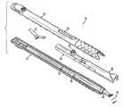
- FIG. 1is a perspective view of an embodiment of the present invention with the guard in a retracted position to expose the blade;
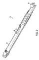
- FIG. 2is a perspective view of an embodiment of the present invention with the guard in an extended position to shield the blade;
- FIG. 3is an exploded perspective view of an embodiment of the present invention.
- FIG. 4is a cross-sectional view of an embodiment of the present invention taken along line A-A of FIG. 1 ;
- FIG. 5Ais a perspective view of an embodiment of the engagement between the guard positioning mechanism and the guard in accordance with an embodiment of the present invention
- FIG. 5Bis a cross-sectional view of an embodiment of the engagement end of the guard in FIG. 5A ;
- FIG. 5Cis a perspective view of an embodiment of the engagement end of the guard in FIG. 5A ;
- FIG. 5Dis a cross-sectional view of an embodiment of the engagement end of the guard positioning mechanism in FIG. 5A ;
- FIG. 5Eis a perspective view of an embodiment of the engagement end of the guard positioning mechanism in FIG. 5A ;
- FIG. 6is an enlarged cross-sectional view of an embodiment of the guard positioning mechanism and the guard in accordance with an embodiment of the present invention taken along line B-B of FIG. 1 ;
- FIG. 7is an enlarged cross-sectional view of an embodiment of the guard positioning mechanism and the guard in accordance with an embodiment of the present invention taken along line C-C of FIG. 1 ;
- FIG. 8Ais a cross-sectional view of a second version of the embodiment of FIG. 1 illustrating a guard positioning mechanism having an integral spring;
- FIG. 8Bis an enlarged cross-sectional view of the detent engagement of the integral spring of FIG. 8A ;
- FIG. 8Cis an enlarged cross-sectional view of the detent engagement of the leaf spring of FIG. 3 ;
- FIG. 8Dis a side view of the guard positioning mechanism and integral spring of FIG. 8A ;
- FIG. 8Eis a bottom view of the guard positioning mechanism and integral spring of FIG. 8A ;
- FIG. 8Fis a perspective view of the guard positioning mechanism and integral spring of FIG. 8A ;
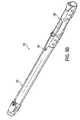
- FIG. 9Ais a perspective view of another embodiment of the present invention with the guard in a retracted position to expose the blade;
- FIG. 9Bis a perspective view of the embodiment of FIG. 9A with the guard in an extended position to shield the blade;
- FIG. 10is an exploded perspective view of the embodiment of FIG. 9A ;
- FIG. 11is an enlarged cross-sectional view of the embodiment of FIG. 9A taken along line D-D of FIG. 9A ;
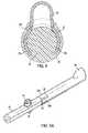
- FIG. 12Ais a perspective view of another embodiment of the present invention with a plunger type operator control and the guard in an extended position to shield the blade;
- FIG. 12Bis a perspective view of the embodiment of FIG. 12A with a plunger type operator control and the guard in a retracted position to expose the blade;
- FIG. 12Cis a perspective view of another embodiment of the present invention with a segmented plunger type operator control and the guard in a retracted position to expose the blade.
- the embodiment of the present invention described belowdiscloses a surgical knife safety handle, for both ophthalmic and non-ophthalmic applications, having a movable guard that can be retracted to expose the blade when in use, and that can be extended to cover the sharp cutting edge of the blade when not in use.
- the guardis located at a distal end of the handle, partially extending from inside the handle, and including a larger diameter shielding end which becomes part of the exposed handle when fully retracted. When fully extended, the guard covers the exposed cutting edge of the blade without distorting handle contours.
- the guardis engaged with a drive mechanism slidably mounted within the handle body, which includes a leaf spring for engaging detents at fully extended and fully retracted positions, and providing audible and tactile engagement feedback. The engagement between the guard and drive mechanism also serves to prevent guard displacement when fully extended except through drive mechanism control.
- the surgical knife safety handle 10 of the present inventionincludes a body 20 having a guard 30 slideably received partially within body 20 for longitudinal sliding movement between a retracted and extended position.
- FIG. 1is a perspective view of an embodiment of the present invention with the guard 30 in a retracted position to expose a blade 40 for use.
- the guard 30when in the retracted position, forms a smooth, uninterrupted handle surface between distal and proximal ends, which is preferred by users of such devices when in use.
- the enlarged guard portionexternal to body 20 when fully retracted, defines a noncircular contour about the distal end of the surgical knife safety handle 10 which gives the user better control and allows easier blade orientation during use.
- proximalrefers to a location on the surgical knife safety handle 10 closest to the person using the device handle and farthest from the patient in connection with which the device handle is used.
- distalrefers to a location on the device handle of this invention farthest from the person using the device handle and closest to the patient in connection with which the device handle is used.
- the surgical knife safety handle 10 of the present inventionalso includes a blade 40 , or similar device, fixedly secured to the distal end of body 20 .
- a blade 40or similar device, fixedly secured to the distal end of body 20 .
- exposed bladessuch as this present several hazards, including accidental cuts of hospital personnel and blade damage.
- the guard 30can be slideably extended from the distal end of body 20 to shield the exposed blade 40 as shown in FIG. 2 .
- FIG. 2is a perspective view of an embodiment of the present invention with the guard 30 in an extended position.
- a leaf spring and antitravel mechanismis employed within the body 20 to prevent unwanted movement of the guard 30 when fully extended, as described in greater detail below.
- FIG. 3is an exploded perspective view of an embodiment of the present invention.
- the view of FIG. 3includes an upper body contour wall 22 and a lower body contour wall 24 , formed to assemble as a handle body 20 and define a substantially hollow chamber within the body 20 to house a guard positioning mechanism 50 and a concealable portion of guard 30 .
- the upper body contour wall 22includes a slot 28 accessing the chamber to allow protrusion of a raised operator control 58 for the guard positioning mechanism 50 , which can be collectively referred to as a user actuator.
- the distal end of the upper body contour wall 22also includes an outer surface having a dimpled texture, extending from the distal end of the upper body contour wall 22 to a point slightly before the access slot 28 .
- the textured surfaceis sufficient to provide the user with a nonslip grip during use, and is duplicated in a similar position on the lower body contour wall 24 such that when assembled, the textured surface appears uniform about an outside diameter of the body 20 near the distal end.
- a dimpled surfaceis shown in the embodiment in FIG. 3 , any nonslip surface can be used. Additionally, the nonslip surface can be extended or modified from the area shown and described in FIG. 3 as required in other embodiments.
- the distal end of the upper body contour wall 22further includes a semicircular mating port, extending rearward from the distal end, and providing a position in which the raised contoured surface of the exposed portion of the guard 30 is seated when fully retracted. In the fully retracted position, the mating port and exposed guard portion of the guard 30 are configured to provide the smooth, uninterrupted handle surface and noncircular contour about the distal end as described above.
- the upper body contour wall 22 and lower body contour wall 24assemble to form the handle body 20 and define a substantially hollow chamber within the body 20 to house a guard positioning mechanism 50 and a concealable portion of guard 30 .
- the guard positioning mechanism 50which is described in greater detail below and shown in FIG. 5A , has a generally cylindrical cross section and is sized to slidably fit within the hollow chamber within the body 20 .
- the guard positioning mechanism 50is controlled to travel between a fully extended and fully retracted position via an external protrusion 58 accessed through channel 28 . Each position is maintained by an engagement between a leaf spring 52 , which is contained within a body cavity of the guard positioning mechanism 50 , and either a first or second detent 54 and 56 in the lower body contour wall 24 as described below.
- the lower body contour wall 24includes a first and second detent 54 and 56 to engage the leaf spring 52 of the guard positioning mechanism 50 , locking the guard in position when fully extended or fully retracted.
- the upper body contour wall 22 and lower body contour wall 24assemble to define a substantially hollow chamber within the body 20 to house the guard positioning mechanism 50 which contains a leaf spring 52 , wherein the leaf spring is oriented within the guard positioning mechanism 50 to firmly press against the lower body contour wall 24 when sliding between extended and retracted positions.
- the lower body contour wall 24includes a first and second detent 54 and 56 , located at opposite positions within the substantially hollow chamber such that the leaf spring engages the first detent 54 when the guard positioning mechanism 50 is in a fully retracted position, and engages the second detent 56 when the guard positioning mechanism 50 is in a fully extended position. Slidable movement of the guard positioning mechanism 50 between positions is opposed with a slight resistance created by the leaf spring 52 contact with the lower body contour wall 24 between detents.
- the engagement between spring and either detentalso provides audible and tactile engagement feedback to the user.
- the engagementproduces an audible sound, such as a “click”, when fully extended or fully retracted, and the spring is properly engaged. Also, the proper engagement also produces a mechanical vibration pulse, or tactile feedback, which allows the user to ensure engagement has occurred.
- the distal end of the lower body contour wall 24also includes a tapered blade holder 26 , or post, configured to fixedly secure the blade 40 to the distal end of body 20 .
- the tapered blade holder 26is molded as an extension of the lower body contour wall 24 distal end and has a generally circular cross section area at a point of attachment, and is tapered slightly to a reduced cross section area at a point of attachment to the blade 40 , which can be epoxy bonded to the holder.
- FIG. 4is a cross-sectional view of an embodiment of the present invention taken along line A-A of FIG. 1 , showing the point of attachment between the holder 26 and the lower body contour wall 24 , and the semicircular opening at the distal end of the body 20 through which the guard is extended and retracted during use.
- the cross section shown in FIG. 4also shows the enlarged distal end of the guard 30 , which is required to provide sufficient clearance for the blade when fully extended. This enlarged distal end is shown as one example, an may be modified to accommodate any blade type or guarding purpose.
- the molded connection between holder 26 and the lower body contour wall 24provides a first and second slot 27 a and 27 b on either side of the holder 26 , for use in guiding the guard 30 between extended and retracted positions and preventing twisting or distortion.
- the assembly of body contour walls 22 and 24creates a third slot 27 c between contour wall 22 and the holder 26 , linking slots 27 a and 27 b , such that a continuous semicircular slot is provided at the distal end, about the holder 26 , through which the guard 30 travels between fully extended and fully retracted positions.
- the guard 30has a generally semicircular cross section and is sized at a proximal end to extend and retract through the semicircular distal opening provided by the body 20 , and is enlarged at a distal end to surround the blade 40 without interference when extended.
- the guard 30can be constructed of any suitable material, including transparent or opaque polycarbonate materials. A transparent guard is advantageous in allowing the user to see the blade 40 even when it is fully shielded by the guard.
- the guard 30does not have a fully circular cross section at the distal end due to the molded attachment of the holder 26 to the lower body contour wall 24 .
- This featureensures the user is allowed to firmly grip a surface that is singularly molded with the blade holder 26 . This presents a more positive grip which is less susceptible to unwanted blade or gripping surface movements due to tolerances between the guard 30 and each body contour wall 22 and 24 .
- the enlarged distal end of the guard 30which remains external to the body 20 when fully retracted however, is rigid enough to provide additional control and blade orientation with one or more fingers of the user if so desired during use.
- FIGS. 5A-5E , 6 and 7show additional details of the guard positioning mechanism 50 and the guard 30 .
- FIG. 5Aillustrates the engagement between the guard positioning mechanism and the guard
- FIGS. 6 and 7illustrate an enlarged cross-sectional view of the engagement shown and described in relation to the body 20 .
- FIGS. 5B-5Eprovide additional views of the engagement mechanisms of both the guard positioning mechanism and the guard.
- the guard positioning mechanism 50has a generally circular cross section and is sized to slidably fit within the hollow chamber within the body 20 .
- the guard positioning mechanism 50is mechanically engaged with the guard 30 to direct and control guard travel between a fully extended and fully retracted position.
- the combined length of the mechanism 50 and guard 30is sufficient to allow a substantial portion of the guard 30 to retract within body 20 . Only a partial radius of the enlarged distal end of the guard 30 remains exposed as shown in FIG. 1 .
- the guard positioning mechanism 50is mechanically engaged with the guard 30 via a tapered locking pin located at an engagement end of the guard positioning mechanism 50 and described in greater detail below.
- the mechanical engagement between positioning mechanism 50 and guard 30allows the positioning mechanism 50 to control the slidable movement of the guard 30 between extended and retracted positions.
- External control of the guard positioning mechanism 50is directed by the user via the raised protrusion 58 which extends from within the hollow chamber of the body 20 via channel 28 . The ease of control allows the user one finger control of the positioning mechanism and the attached guard.
- each position of the guard 30is maintained by an engagement between a leaf spring 52 , located within a body cavity of the guard positioning mechanism 50 , and either a first or second detent 54 and 56 located in the lower body contour wall 24 .
- the guard positioning mechanism 50is substantially hollow and contains a leaf spring 52 which is oriented within the guard positioning mechanism 50 with an exposed spring apex extending from the guard positioning mechanism 50 via an opening 60 .
- the spring apex extending from opening 60firmly presses against the lower body contour wall 24 when sliding between extended and retracted positions.
- the lower body contour wall 24includes a first and second detent 54 and 56 , located at opposite positions within the substantially hollow chamber such that the leaf spring engages the first detent 54 when the guard positioning mechanism 50 is in a fully retracted position, and engages the second detent 56 when the guard positioning mechanism 50 is in a fully extended position. Slidable movement of the guard positioning mechanism 50 between positions through the use of a prevailing force is opposed with a slight resistance created by the leaf spring 52 contact with the lower body contour wall 24 between detents. The slight resistance provided allows the guard 30 to maintain a position when the user releases the external control 58 , and prevents the guard from freely sliding.
- the guard 30extends between a generally circular cross section at a proximal end, and a generally semicircular cross section at an enlarged distal end.
- the guardis not fully circular along it's entire length due to the need to surround the molded attachment of the holder 26 and the blade 40 , which is in rigid attachment to the body via the lower body contour wall 24 . Therefore the guard 30 includes opposite engagement and shielding ends.
- the guardAt the engagement, or proximal end, the guard has a generally circular cross section and is sized to slidably fit within the hollow chamber within the body 20 , and mechanically engage the guard positioning mechanism 50 which directs and controls the travel of the guard 30 between a fully extended and fully retracted position as described above.
- the engagement end of the guard 30is described in greater detail below.
- the shielding, or distal end of the guard 30 shown in FIG. 5Ahas a generally semicircular cross section and is sized to extend and retract through the semicircular distal opening provided by the body 20 .
- An enlarged semicircular areais provided at the extreme end of the distal end of the guard 30 to provide adequate clearance of the blade 40 when the guard 30 is fully extended. Additionally, as noted above, the enlarged semicircular area provided at the extreme distal end of the guard 30 remains external to the body 20 when the guard is fully retracted, and is rigid enough to provide additional control and blade orientation with one or more fingers of the user if so desired.
- the engagement, or proximal end of the guard 30includes a coupling mechanism having four flanges 34 a , 34 b , 34 c and 34 d , to engage the tapered locking pin 62 located at the engagement end of the guard positioning mechanism 50 .
- the engagement end of the guard positioning mechanism 50includes a tapered locking pin 62 having four surface quadrants 62 a , 62 b , 62 c , and 62 d .
- the coupling mechanism of the guard 30engages the four surface quadrants 62 a , 62 b , 62 c , and 62 d of the tapered locking pin 62 using the four flanges 34 a , 34 b , 34 c and 34 d extending from the engagement end of the guard and surrounding a mating opening for the locking pin 62 .
- Flanges 34 a and 34 care located on opposite sides of the mating opening and are used to engage surface quadrants 62 a and 62 c of locking pin 62 to achieve mechanical engagement.
- Flanges 34 b and 34 dare also located on opposite sides of the mating opening and are used to engage surface quadrants 62 b and 62 d of locking pin 62 to achieve antitravel engagement.
- FIGS. 5A-5E and 6Mechanical engagement between guard positioning mechanism 50 and the guard 30 is shown in FIGS. 5A-5E and 6 .
- FIG. 6is an enlarged cross-sectional view showing the locked engagement between flanges 34 a and 34 c , and pin quadrants 62 a and 62 c .
- FIG. 7is an enlarged cross-sectional view rotated 90 degrees relative to the view of FIG. 6 , and showing the potential for engagement between flanges 34 b and 34 d , and pin quadrants 62 b and 62 d.
- the locking pin 62is inserted into the coupling mechanism of the guard 30 until locked into place by locking flanges 34 a and 34 c .
- the locking pin 62is inserted into the four locking flanges 34 a , 34 b , 34 c and 34 d extending from the body of the guard 30 .
- the locking pin 62is tapered along quadrants 62 a and 62 c , allowing an inner lip 32 , located about the inside circumference of two locking flanges 34 a and 34 c , to displace the flanges outward until the inner lip 32 is disposed into the groove 64 near the base of the locking pin 62 , locking the guard into place.
- the inner lip 32engages the groove 64 located about the outside circumference of the locking pin 62 , preventing the separation of guard 30 and guard positioning mechanism 50 .
- the two locking flanges 34 a and 34 care made of a material sufficiently pliant to allow displacement outward due to the insertion of locking pin 62 , yet maintain engagement between the inner lip 32 and groove 64 during movement of the guard positioning mechanism 50 .
- Antitravel engagement between guard positioning mechanism 50 and the guard 30is shown in FIGS. 5A-5E and 7 .
- additional movement of the guard 30 and guard positioning mechanism 50 towards one anotherwill engage an antitravel mechanism incorporated into the coupling mechanism components described above.
- Travel of the guard 30 towards a stationary guard positioning mechanism 50indicates a force, not properly originating from the user, is acting in a manner to retract the guard.
- Such forcescan result from a number of causes, including external forces applied to the guard when fully extended. Examples include instances where the extended guard 30 is bumped or struck. Such forces could result in the guard partially retracting and exposing part or all of the blade 40 .
- an antitravel mechanismis engaged when the guard 30 is fully extended, and an external force is applied to the guard which would tend to force the guard from the fully extended position against the resistance of the guard positioning mechanism 50 .
- the locking flanges 34 b and 34 d extending from the body of the guard 30each include an inner ramp 36 , which engages the surface quadrants 62 b and 62 d of the locking pin 62 of the guard positioning mechanism 50 when the guard 30 is moved towards the guard positioning mechanism beyond the locking point described above.
- Quadrants 62 b and 62 dinclude a slight flat along the taper of the pin such that in a normal, engaged position, the inner ramp contacts 36 do not displace the flanges 34 b and 34 d .
- the flanges 34 b and 34 donce fully displaced within the groove 38 , travel along the groove a minute distance until contacting a shoulder at the end of each groove, stopping any further travel of the flanges in a rearward direction, thus preventing any noticeable retracting movement of the guard 30 from the fully extended position.
- Flanges 34 a and 34 calso work in cooperation to achieve the antitravel function.
- the groove 64 which is engaged by the inner lip 32 of flanges 34 a and 34 chas a sufficient width to allow the inner lip to travel slightly rearward during engagement of the antitravel mechanism, such that the flanges 34 a and 34 c do not interfere with the function of the antitravel mechanism of flanges 34 b and 34 d . If the inner lip 32 were not allowed to travel in the groove 64 , any rearward force on the guard 30 would displace the guard positioning mechanism 50 before the antitravel mechanism could engage.
- flanges 34 a and 34 ccan include an inner surface of flanges 34 a and 34 c each including a slight relief (not shown), which prevents the flanges from possibly displacing slightly outwards when inner lip 32 is engaged in the groove 64 , due to flange thickness and the surface of pin 62 .
- flanges 34 b and 34 dare slightly shorter than flanges 34 a and 34 c , allowing the mechanical engagement to occur within the chamber housing without interference.
- the resistance provided by the leaf spring 52 engagement with the fully extended detent slot 56is sufficient to hold the guard positioning mechanism 50 in place when an external force is applied to the fully extended guard 30 .
- the guard positioning mechanism 50remains in position as the guard 30 is slightly displaced rearward activating the antitravel mechanism incorporated into the coupling mechanism as described above. In this embodiment, the slight rearward displacement prior to full activation of the antitravel mechanism is negligible.
- the guard positioning mechanism 50 of the user actuatorcan be constructed with an integral cantilever beam spring to provide the spring biasing mechanism forcing detent engagement.
- the guard positioning mechanism 50has an integral cantilever beam 70 , secured at a first end and flexing at an opposite end upon which an inclined projection 72 is used to provide the spring biasing mechanism.
- This plastic molded springcan be used to replace the leaf spring 52 and maintain each position of the guard 30 by an engagement between the molded spring and the first or second detent 54 and 56 located in the lower body contour wall 24 .
- the guard positioning mechanism 50includes at least one inclined projection 72 , wherein the incline (i.e., 45 degrees) is provided to allow easy entry and removal from the detents.
- the integral cantilever beam 70firmly presses the projection 72 against the lower body contour wall 24 when sliding between extended and retracted positions.
- the lower body contour wall 24includes a first and second detent 54 and 56 , located at opposite positions within the substantially hollow chamber such that the projection 72 engages the first detent 54 when the guard positioning mechanism 50 is in a fully retracted position, and engages the second detent 56 when the guard positioning mechanism 50 is in a fully extended position.
- the use of the integral cantilever beam 70 and the inclined projection 72eliminates the need for a metal spring component.
- the spring biasing mechanismtherefore becomes part of the user actuator (i.e., raised operator control 58 and guard positioning mechanism 50 ), and all can be made from one piece of material. This reduces variability in the “feel” when moving the guard positioning mechanism 50 between positions (i.e., in and out of detent engagements).
- the metal leaf spring component 52when the metal leaf spring component 52 is assembled into the guard positioning mechanism 50 , the dimensions of the metal spring component can be altered due to the nature of the assembly method required. Additionally, the metal leaf spring can have a reduced cycle life relative to the plastic molded spring, and can deform after few detent engagements.
- the spring biasing mechanism and the user actuatorinto one, thus eliminating one of the two parts, allows for tighter tolerances between the remaining components (i.e., detent and spring biasing mechanism). Furthermore, the variability incurred as part of the assembly method between the metal leaf spring component and the user actuator is also removed. The tighter tolerances and removal of the assembly method added variability ensures smooth and consistent detent engagement. As with the above embodiments, the smoother detent engagements also provide feedback to the user through an audible click and a mechanical snap that can be felt through the user actuator.
- the integral cantilever beam 70 and inclined projection 72can be modified in shape and form, and still act as the spring biasing mechanism.
- the cantilever spring 70 and inclined projection 72can be molded into the lower body contour wall 24 (i.e. handle base) and the detents 54 and 56 placed into the guard positioning mechanism 50 of the user actuator, thereby reversing the locations of these two features.
- a fully circular guardmay also be used to shield the exposed blade.
- the guardis fully circular at the distal end, which allows a larger portion of the guard to remain exposed when fully retracted.
- FIG. 9Ais a perspective view of a second embodiment of the present invention 100 with the guard 130 in a retracted position to expose a blade 140 for use.
- the guard 130when in the retracted position, forms a smooth, uninterrupted handle surface between distal and proximal ends substantially as described in the first embodiment.
- the guard 130can be extended, as shown in FIG. 9B , to safely shield the blade 140 .
- FIG. 10is an exploded perspective view of a second embodiment of the present invention.
- the view of FIG. 10includes a first and second body contour wall 122 and 124 , formed to assemble as a handle body 120 and define a substantially hollow chamber within the body 120 to house a concealable portion of the guard 130 .
- the first and second body contour walls 122 and 124each provide a recess, which when assembled, creates a slot 128 extending rearward from the distal end and accessing the chamber to allow protrusion of a raised operator control 158 for the guard 130 .
- the distal end of the first and second body contour wall 122 and 124also includes an outer surface having a dimpled texture, extending from the distal end to a point slightly before the midpoint of the access slot 128 . Additionally, as shown FIGS. 9A and 9B , the outer circumference surface area of an exposed portion of guard 130 also includes a dimpled texture, such that when fully retracted, the dimpled texture surface area is unbroken about the distal end of the body 120 .
- the distal ends of both the first and second body contour wall 122 and 124further include a reduced outside diameter for receiving the exposed portion of guard 130 .
- the fully circular exposed portion of guard 130is received by the reduced outside diameter of the first and second body contour wall 122 and 124 , until reaching a shoulder at the fully retracted position.
- Seating the guard 130 against the shoulder of the reduced outside diameterforms the smooth, uninterrupted handle surface between distal and proximal ends described above.
- the guard 130is controlled to travel between a fully extended and fully retracted position via an external protrusion 158 accessed through channel 128 in a manner substantially as described in the first embodiment.
- each positionis maintained by an engagement between a spring 152 within a body cavity of the guard positioning mechanism 50 and either a first or second slot 154 and 156 , provided along rails at either side of the hollow chamber within the body 120 .
- the chamber, slots and railsare formed as described below, and serve to provide a slidable engagement surface for the guard to travel between fully extended and fully retracted positions.
- the first and second body contour wall 122 and 124assemble to define a substantially hollow chamber within the body 120 to house the guard 130 which contains a spring 152 mounted beneath a saddle 160 that is driven between rails on either side of the chamber.
- the guard 130includes a fully circular distal end, provided to shield the blade 140 when fully extended.
- An elongated member 132extends rearward from the from the fully circular distal end, and provides a platform supporting a saddle 160 , a plate 136 , an external protrusion 158 and a contoured end 134 .
- each body contour 122 and 124provides a first and second rail 162 and 164 , along the inner wall of the chamber.
- the first rail 162is provided to engage the spring 152 , as described in greater detail below.
- the second rail 164is provided to engage the saddle 160 , and maintain saddle alignment between fully extended and retracted guard positions.
- the first rail 162is provided between saddle 160 and spring 152 .
- the spring 152is mechanically attached to the bottom of the saddle 160 and includes an extension having a 90 degree angle oriented to firmly press against the upper surface of the first rail 162 when sliding between extended and retracted positions.
- the upper surface of the first rail 162 of each contour wall 122 and 124includes a first and second slot 154 and 156 , located at opposite positions along the substantially hollow chamber such that the spring 152 engages the first slot 154 when the guard 130 is in a fully retracted position, and engages the second slot 156 when the guard is in a fully extended position. Slidable movement of the guard 130 between positions is opposed with a slight resistance created by the spring 152 contact with the rail surface on either side of the chamber.
- the second body contour wall 124can include a recessed groove 166 extending along the surface of the distal end beneath the elongated member 132 .
- a plate(not shown), extending below the elongated member, can be used to slidably engage the recessed groove 166 of wall 124 , providing alignment and support for the elongated member 132 and the fully circular distal end of the guard 130 when traveling between fully extended and fully retracted positions.
- the guard 130is locked in place.
- To disengage the spring 152requires the user to apply slight perpendicular pressure to the external protrusion 158 until the spring 152 is disengaged from the slot, and thereafter, a parallel force can be used to slidably move the guard 130 to a new position.
- the spring 152is oriented to firmly press against the surface of the first rail when sliding between extended and retracted positions, and maintain a position in the first or second slot when at extended or retracted positions.
- the guard 130includes the elongated member 132 extending into the chamber and contacting a surface via a contoured end 134 .
- the guard 130also includes a slight notch 138 at a point between the saddle 160 and a plate 136 extending downward and contacting the spring 152 .
- a slight perpendicular pressure applied to the external protrusion 158is transferred to the elongated member 132 .
- the contact at the contour 134 , and the slight notch at 138allows the perpendicular pressure to displace the plate 136 downward, forcing the spring 152 from the slot.
- the plate 136is slightly narrower than the spring 152 , therefore the plate can freely move between rails and deflect the wider spring 152 from contact with rail 162 .
- the protrusion 158can provide simple and safe one finger control of the guard 130 .
- the first and second body contour wallassemble to define a substantially hollow chamber within the body to house the guard which contains a spring mounted beneath a saddle that is driven between rails on either side of the chamber substantially as described above.
- the springis oriented to contact the bottom of the chamber and firmly press the saddle against the surface of at least one rail provided when sliding between extended and retracted positions.
- Each contour wallincludes a first and second slot, located at opposite positions along at least one rail within the substantially hollow chamber such that the saddle, under pressure from the spring, engages the first slot when the guard is in a fully retracted position, and engages the second slot when the guard is in a fully extended position.
- the guardis locked in place.
- To disengage the saddlerequires the user to apply slight perpendicular pressure to the external protrusion until the saddle is disengaged from the slot, and thereafter, a parallel force can be used to slidably move the guard to a new position.
- FIGS. 12A and 12Bare perspective views of the third embodiment of the present invention with a plunger type operator control and the guard in an extended and retracted position, respectively.
- Such mechanisms 255typically involve a user activated plunger to advance a pen tip outward or to retract a pen tip inward in a longitudinal direction.
- the use of a pen mechanism at the proximal end of the devicecan provide an alternative to the side slot described in regards to the above embodiments. This would allow further variations in the single handed use of the embodiments described above.
- Such a pen mechanismwould utilize features similar to those in current pens to move the blade guard back and forth, as opposed to extending and retracting a pen tip.
- a user actuatorcan be located on the proximal end of the device that functions like a pen mechanism, i.e. to click the guard in or out.
- the mechanismcould include a simple, single cylindrical member 250 extending from the proximal end opening 254 along the axis of the device body, 220 , and operate in a click-in and click-out fashion with an extension/retraction mechanism 255 as known to those skilled in the art.
- the mechanismcould include a cylindrical member extending from the proximal end along the axis of the device and being divided into two or more members, or segments, 256 and 258 as shown in FIG. 12C .
- the divided memberswhen together, form the single cylindrical member; however each member can move relative to the others and provide an action unique to the movement of the particular divided member.
- Related divided function mechanismscan be found in multi-colored ballpoint pen mechanisms, which include different push button segments to extend different colors of pen tips from a single device.
- various guardscould be fabricated to fit inside and/or outside the body and/or chamber of the handle and still achieve the desired coverage of the blade.
- the handle or body of the devicecan be constructed with a smaller diameter, or allow for the guard to better shield the blades described above or other blade geometry.
- the guardscould further comprise various shapes which can provide blade shielding at various places or of various strengths. Specifically, different guard shapes may provide different strength characteristics, and further allow the guard to withstand higher forces. These may also allow for a smaller guard, or enlarged guard distal end, thereby minimizing visual interference with the blade while providing maximum protection from blade contact resulting in a blade stick.
- Such a guard designcan be either completely inside, outside or a combination of both, and the guard and enlarged guard distal end can be either open or closed, and can achieve full circumference protection or provide alternative means to shield a blade depending on blade design.
- the guard and enlarged guard distal endcan still include other shapes, such as, but not limited to, triangle, square and/or box shapes, and still other shapes having multiple facets or sides, all with or without a circular or radius cross section, but which still provide shielding for blades of different geometry.
- the spring biasing mechanism that provides detent engagement within such a pen mechanismcan include any number of configurations, such as the leaf spring and a cantilever beam described above, or a compression/extension spring.
- the springsuch as the leaf spring, could be replaced with another spring biasing mechanism forcing detent engagement.
- the springcould provide a sufficient resistive force necessary for the guard function.
- the guard and enlarged guard distal endcan be configured to withstand forces up to 3 lbs. in one example. Where such a spring biasing mechanism is used, the required applied force would typically be equal to or greater than the force which the guard can withstand.
- the spring biasing mechanismmay be used to reduce the force required to move the guard back and forth, or to strengthen the guard design in each embodiment described above.
- embodiments of the present inventioncan withstand an inadvertent force. Such protection can be provided by utilizing an internal locking feature (i.e. a third detent) as described in greater detail above. These embodiments do not disengage or allow the guard to move from the shielding state to the non-shielding state by any reasonable inadvertent force applied longitudinally to the guard. Each embodiment therefore is able to implement a lock-out feature.
- an internal locking featurei.e. a third detent
- the embodiments of the present inventioncan be constructed of any suitable material, including a number of materials which can be autoclaved for repeated use.
- a preferred blade 40 and spring 52 materialincludes stainless steel (for metal spring versions only), and the body 20 and guard positioning mechanism 50 can be constructed of polyetherimide.
- the guard 30can be constructed of transparent or opaque polycarbonate. Where the leaf spring 52 is omitted and replaced with an integral cantilever beam 70 and inclined projection 72 , the beam and projection can also be constructed of a polyetherimide.
- blade materialscan be provided, including silicon, and the body 20 can be constructed of autoclave intolerant materials, such as high impact polystyrene.
- high impact polystyrenewill result in the substantial destruction of the device when autoclaved, thereby preventing reuse.
- the leaf spring 52can be constructed of stainless steel (for metal spring versions only), and the guard positioning mechanism 50 and guard 30 can be constructed of polyetherimide and polycarbonate, respectively.
Landscapes
- Health & Medical Sciences (AREA)
- Life Sciences & Earth Sciences (AREA)
- Surgery (AREA)
- Veterinary Medicine (AREA)
- Public Health (AREA)
- Biomedical Technology (AREA)
- Heart & Thoracic Surgery (AREA)
- Engineering & Computer Science (AREA)
- Nuclear Medicine, Radiotherapy & Molecular Imaging (AREA)
- Animal Behavior & Ethology (AREA)
- General Health & Medical Sciences (AREA)
- Ophthalmology & Optometry (AREA)
- Molecular Biology (AREA)
- Medical Informatics (AREA)
- Vascular Medicine (AREA)
- Surgical Instruments (AREA)
- Knives (AREA)
Abstract
Description
Claims (11)
Priority Applications (9)
| Application Number | Priority Date | Filing Date | Title |
|---|---|---|---|
| US10/828,501US7387637B2 (en) | 2003-04-22 | 2004-04-21 | Surgical knife safety handle |
| US11/980,414US7905894B2 (en) | 2003-04-22 | 2007-10-31 | Surgical knife safety handle |
| US11/980,436US7901422B2 (en) | 2003-04-22 | 2007-10-31 | Surgical knife safety handle |
| US12/929,014US10258367B2 (en) | 2003-04-22 | 2010-12-22 | Surgical knife safety handle |
| US29/371,480USD685091S1 (en) | 2003-04-22 | 2011-03-14 | Surgical knife safety handle guard |
| US29/371,481USD685092S1 (en) | 2003-04-22 | 2011-03-14 | Surgical knife safety handle |
| US13/831,668US10271872B2 (en) | 2003-04-22 | 2013-03-15 | Surgical knife safety handle |
| US16/395,923US11134979B2 (en) | 2003-04-22 | 2019-04-26 | Surgical knife safety handle |
| US17/491,872US20220015794A1 (en) | 2003-04-22 | 2021-10-01 | Surgical knife safety handle |
Applications Claiming Priority (3)
| Application Number | Priority Date | Filing Date | Title |
|---|---|---|---|
| US10/420,614US7022128B2 (en) | 2003-04-22 | 2003-04-22 | Surgical knife safety handle |
| US51961403P | 2003-11-14 | 2003-11-14 | |
| US10/828,501US7387637B2 (en) | 2003-04-22 | 2004-04-21 | Surgical knife safety handle |
Related Parent Applications (2)
| Application Number | Title | Priority Date | Filing Date |
|---|---|---|---|
| US10/420,614Continuation-In-PartUS7022128B2 (en) | 2003-04-22 | 2003-04-22 | Surgical knife safety handle |
| US10/426,614Continuation-In-PartUS7204899B2 (en) | 2003-04-30 | 2003-04-30 | Apparatus and method for mechanically bonding and cutting an article |
Related Child Applications (2)
| Application Number | Title | Priority Date | Filing Date |
|---|---|---|---|
| US11/980,436DivisionUS7901422B2 (en) | 2003-04-22 | 2007-10-31 | Surgical knife safety handle |
| US11/980,414DivisionUS7905894B2 (en) | 2003-04-22 | 2007-10-31 | Surgical knife safety handle |
Publications (2)
| Publication Number | Publication Date |
|---|---|
| US20050015104A1 US20050015104A1 (en) | 2005-01-20 |
| US7387637B2true US7387637B2 (en) | 2008-06-17 |
Family
ID=33313116
Family Applications (5)
| Application Number | Title | Priority Date | Filing Date |
|---|---|---|---|
| US10/828,501Expired - LifetimeUS7387637B2 (en) | 2003-04-22 | 2004-04-21 | Surgical knife safety handle |
| US11/980,436Expired - LifetimeUS7901422B2 (en) | 2003-04-22 | 2007-10-31 | Surgical knife safety handle |
| US11/980,414Expired - LifetimeUS7905894B2 (en) | 2003-04-22 | 2007-10-31 | Surgical knife safety handle |
| US12/929,014Expired - LifetimeUS10258367B2 (en) | 2003-04-22 | 2010-12-22 | Surgical knife safety handle |
| US13/831,668Expired - LifetimeUS10271872B2 (en) | 2003-04-22 | 2013-03-15 | Surgical knife safety handle |
Family Applications After (4)
| Application Number | Title | Priority Date | Filing Date |
|---|---|---|---|
| US11/980,436Expired - LifetimeUS7901422B2 (en) | 2003-04-22 | 2007-10-31 | Surgical knife safety handle |
| US11/980,414Expired - LifetimeUS7905894B2 (en) | 2003-04-22 | 2007-10-31 | Surgical knife safety handle |
| US12/929,014Expired - LifetimeUS10258367B2 (en) | 2003-04-22 | 2010-12-22 | Surgical knife safety handle |
| US13/831,668Expired - LifetimeUS10271872B2 (en) | 2003-04-22 | 2013-03-15 | Surgical knife safety handle |
Country Status (12)
| Country | Link |
|---|---|
| US (5) | US7387637B2 (en) |
| EP (1) | EP1615568B1 (en) |
| JP (2) | JP4746538B2 (en) |
| KR (1) | KR101119203B1 (en) |
| AU (1) | AU2004232315B2 (en) |
| BR (1) | BRPI0409610B8 (en) |
| CA (1) | CA2522763C (en) |
| ES (1) | ES2531366T3 (en) |
| MX (1) | MXPA05011312A (en) |
| NO (1) | NO337739B1 (en) |
| TW (1) | TW200509851A (en) |
| WO (1) | WO2004093924A2 (en) |
Cited By (17)
| Publication number | Priority date | Publication date | Assignee | Title |
|---|---|---|---|---|
| US20060085019A1 (en)* | 2004-10-20 | 2006-04-20 | Becton, Dickinson And Company | Surgical knife safety handle having user operable lock |
| US20070270870A1 (en)* | 2006-03-15 | 2007-11-22 | Torrie Paul A | Microfracture Pick |
| US20080051813A1 (en)* | 2004-09-13 | 2008-02-28 | University Of Massachusetts | Adapter Sleeve |
| US20080058843A1 (en)* | 2003-04-22 | 2008-03-06 | Morawski Michael J | Surgical knife safety handle |
| US20100125290A1 (en)* | 2008-11-20 | 2010-05-20 | Gregory Allen Auchter | Guarded surgical knife handle |
| US20100125293A1 (en)* | 2008-11-20 | 2010-05-20 | Gregory Allen Auchter | Guarded surgical knife handle |
| US20100146799A1 (en)* | 2008-12-12 | 2010-06-17 | Unique Technologies Inc. | Guarded Surgical Knife |
| US20100324577A1 (en)* | 2004-09-13 | 2010-12-23 | Raymond Dunn | Scalpel handle |
| DE202009005225U1 (en)* | 2009-09-02 | 2011-01-13 | Süddeutsche Feinmechanik GmbH | curette |
| US20110098734A1 (en)* | 2008-02-07 | 2011-04-28 | Dana Michael Cote | Retractable safety knife |
| USD639432S1 (en) | 2010-08-31 | 2011-06-07 | Oasis Medical, Inc. | Handle for use with a micro surgical knife |
| USD685092S1 (en) | 2003-04-22 | 2013-06-25 | Beaver-Visitec International (Us), Inc. | Surgical knife safety handle |
| USD704337S1 (en) | 2010-04-22 | 2014-05-06 | University Of Massachusetts | Scalpel handle |
| US8875405B2 (en) | 2010-04-09 | 2014-11-04 | Oasis Medical, Inc. | Micro surgical knife with safety feature |
| US10123815B2 (en) | 2015-02-13 | 2018-11-13 | Precision Engineered Products, Llc | Surgical knife |
| US11607243B2 (en) | 2017-06-13 | 2023-03-21 | Conmed Corporation | Soft tissue cutting instrument with retractable blade or hook |
| US11969185B2 (en) | 2018-10-03 | 2024-04-30 | Conmed Corporation | Soft tissue cutting instrument with self locking, multi-position, and slide button linearly actuated retractable blade or hook |
Families Citing this family (27)
| Publication number | Priority date | Publication date | Assignee | Title |
|---|---|---|---|---|
| US11134979B2 (en)* | 2003-04-22 | 2021-10-05 | Beaver-Visitec International (Us), Inc. | Surgical knife safety handle |
| US8016843B2 (en)* | 2005-09-09 | 2011-09-13 | Alcon Research Ltd | Ultrasonic knife |
| US20070060936A1 (en)* | 2005-09-12 | 2007-03-15 | Arthrex, Inc. | Surgical abrader with clear hood |
| US20110004215A1 (en) | 2005-09-12 | 2011-01-06 | Bradley James P | Labrum retracting burr |
| US8114103B2 (en)* | 2005-09-14 | 2012-02-14 | James Edwin Rasco | Scalpel blade protector |
| USD571010S1 (en) | 2006-10-17 | 2008-06-10 | Becton, Dickinson And Company | Surgical knife safety handle |
| US7830070B2 (en)* | 2008-02-12 | 2010-11-09 | Bacoustics, Llc | Ultrasound atomization system |
| US20100152646A1 (en)* | 2008-02-29 | 2010-06-17 | Reshma Girijavallabhan | Intravitreal injection device and method |
| US8197501B2 (en) | 2008-03-20 | 2012-06-12 | Medtronic Xomed, Inc. | Control for a powered surgical instrument |
| JP5537880B2 (en)* | 2009-09-29 | 2014-07-02 | 株式会社貝印刃物開発センター | Medical knife with protective cover |
| USD669988S1 (en)* | 2009-09-29 | 2012-10-30 | Core Surgical Limited | Knife and blade support |
| US8578613B2 (en)* | 2009-10-19 | 2013-11-12 | Ravi Nallakrishnan | Safety knife with curved guard |
| USD642682S1 (en)* | 2010-05-21 | 2011-08-02 | Surgistar, Inc. | Retractable surgical safety knife |
| GB2487950A (en)* | 2011-02-10 | 2012-08-15 | Samuel George | Cutting implement with protective sheath |
| US9872799B2 (en) | 2012-04-24 | 2018-01-23 | The Regents Of The University Of Colorado, A Body Corporate | Intraocular device for dual incisions |
| US10682254B2 (en) | 2012-04-24 | 2020-06-16 | The Regents Of The University Of Colorado, A Body Corporate | Intraocular device for dual incisions |
| AU2014317930B2 (en) | 2013-09-06 | 2018-11-08 | Covidien Lp | Microwave ablation catheter, handle, and system |
| US10201265B2 (en) | 2013-09-06 | 2019-02-12 | Covidien Lp | Microwave ablation catheter, handle, and system |
| USD750780S1 (en) | 2014-02-18 | 2016-03-01 | Mani, Inc. | Surgical knife |
| JP6456701B2 (en)* | 2015-01-27 | 2019-01-23 | 株式会社貝印刃物開発センター | Hand tools |
| USD787056S1 (en) | 2015-03-11 | 2017-05-16 | Jacqueline White | Safety scalpel container |
| US10779991B2 (en) | 2015-12-23 | 2020-09-22 | The Regents of the University of Colorado, a body corporated | Ophthalmic knife and methods of use |
| KR102112244B1 (en)* | 2018-03-21 | 2020-05-19 | (주)메덴 | Medical blade |
| USD922444S1 (en)* | 2018-06-28 | 2021-06-15 | Irobot Corporation | Robotic lawnmower having inwardly indented portions along a periphery thereof |
| USD925738S1 (en)* | 2018-07-25 | 2021-07-20 | Progressive Medical, Inc. | Surgical blade |
| WO2023177761A2 (en) | 2022-03-16 | 2023-09-21 | Sight Sciences, Inc. | Devices and methods for intraocular tissue manipulation |
| JP2025515878A (en)* | 2022-05-13 | 2025-05-20 | ライコ インターナショナル,リミティド ライアビリティ カンパニー | Surgical Instruments for Anterior Goniotomy |
Citations (74)
| Publication number | Priority date | Publication date | Assignee | Title |
|---|---|---|---|---|
| US1195169A (en) | 1916-08-22 | Masvin e | ||
| US1914153A (en) | 1931-09-08 | 1933-06-13 | John J Ogden | Surgical knife |
| US2304332A (en) | 1939-11-10 | 1942-12-08 | Conrad Razor Blade Co Inc | Scraping device |
| US2512237A (en) | 1948-03-12 | 1950-06-20 | Edward E Mravik | Pocket implement |
| US2885780A (en) | 1957-12-03 | 1959-05-12 | Floyd A Campbell | Marking tool |
| US3706106A (en) | 1971-01-18 | 1972-12-19 | Norbert Leopoldi | Surgical knife |
| US3905101A (en) | 1974-04-19 | 1975-09-16 | Becton Dickinson Co | Disposable surgical scalpel |
| US3906626A (en) | 1974-04-19 | 1975-09-23 | Becton Dickinson Co | Disposable surgical scalpel |
| US3943627A (en) | 1973-11-28 | 1976-03-16 | Stanley Jr Conrad | Front loading utility knife |
| US3967377A (en) | 1975-03-17 | 1976-07-06 | Wells Royzell F | Precision positioning device for tool blades and the like |
| US4091537A (en) | 1977-04-26 | 1978-05-30 | Stevenson Machine Shop | Safety utility knife |
| US4375218A (en) | 1981-05-26 | 1983-03-01 | Digeronimo Ernest M | Forceps, scalpel and blood coagulating surgical instrument |
| US4393587A (en) | 1981-04-23 | 1983-07-19 | Kloosterman William A | Spring shielded safety knife |
| US4414974A (en) | 1981-06-09 | 1983-11-15 | General Conveyors Limited | Microsurgical knife |
| US4491132A (en) | 1982-08-06 | 1985-01-01 | Zimmer, Inc. | Sheath and retractable surgical tool combination |
| US4500220A (en) | 1982-09-20 | 1985-02-19 | Pentel Kabushiki Kaisha | Mechanical pencil with removable lead feed cover |
| US4499898A (en) | 1982-08-23 | 1985-02-19 | Koi Associates | Surgical knife with controllably extendable blade and gauge therefor |
| US4516575A (en) | 1982-06-03 | 1985-05-14 | Coopervision, Inc. | Surgical scalpel |
| US4523379A (en) | 1984-05-02 | 1985-06-18 | Tekna | Knife with retractable sheath |
| US4538356A (en) | 1982-08-23 | 1985-09-03 | Koi Associates, Inc. | Surgical knife with controllably extendable blade and gauge therefor |
| US4576164A (en) | 1983-11-14 | 1986-03-18 | Richeson W George | Knife with locking shroud |
| US4630378A (en) | 1985-06-13 | 1986-12-23 | Pilling Co. | Gauge for extensible-blade surgical knife |
| US4660287A (en) | 1985-11-01 | 1987-04-28 | Decker John R | Knife with replaceable blade |
| US4662075A (en) | 1985-08-22 | 1987-05-05 | Magnum Diamond Reclamation, Inc. | Apparatus and method for setting knife blade depth |
| US4719915A (en) | 1985-05-05 | 1988-01-19 | Michael Porat | Scalpel |
| US4735202A (en) | 1986-10-06 | 1988-04-05 | Alcon Laboratories, Inc. | Microsurgical knife with locking blade guard |
| US4757612A (en) | 1985-03-21 | 1988-07-19 | Preposreve S.A.R.L. | Fixed-blade knife with retractable blade cover |
| DE3722899A1 (en) | 1987-07-08 | 1989-01-19 | Peters Tim | Scalpel |
| US4815218A (en) | 1986-06-13 | 1989-03-28 | Cilco, Inc. | Gauge for calibrating surgical scalpel |
| US4823457A (en) | 1988-04-20 | 1989-04-25 | American Safety Razor Company | Disposable surgical scalpel |
| US4825545A (en) | 1986-03-18 | 1989-05-02 | Sabre International Products Limited | Knives with molded protective cover and handle |
| US4826339A (en) | 1987-02-06 | 1989-05-02 | Pentel Kabushiki Kaisha | Dispenser having a flexible nib, slidable sleeve and cap |
| US4910821A (en) | 1989-04-24 | 1990-03-27 | Kieferle Ralph M | Screen installers tool |
| US4958625A (en) | 1989-07-18 | 1990-09-25 | Boston Scientific Corporation | Biopsy needle instrument |
| US4985034A (en) | 1989-06-01 | 1991-01-15 | Board Of Regents, The University Of Texas System | Safety surgical blade, handle and shield |
| US5015252A (en) | 1990-08-13 | 1991-05-14 | Jones Mark W | Surgical forceps with suture cutters |
| US5035703A (en) | 1990-05-09 | 1991-07-30 | Baskas Morris J | Disposable syringe needle and scalpel holder |
| US5071426A (en) | 1989-04-06 | 1991-12-10 | Stuart Dolgin | Surgical scalpel with retractable blade guard |
| US5139507A (en) | 1989-04-06 | 1992-08-18 | Stuart Dolgin | Surgical scalpel with retractable blade guard |
| US5207696A (en) | 1992-04-30 | 1993-05-04 | Medical Sterile Products, Inc. | Surgical scalpel |
| WO1993011916A1 (en) | 1991-12-18 | 1993-06-24 | American Safety Razor Company | Disposable surgical scalpel with safety guard |
| US5222951A (en) | 1992-04-13 | 1993-06-29 | Leonard Bloom | Guarded skin hook for surgical use |
| EP0555196A1 (en) | 1992-01-24 | 1993-08-11 | Michael R. Abidin | Surgical scalpel with retractable guard |
| US5254128A (en) | 1990-10-11 | 1993-10-19 | Micro Engineering, Inc. | Surgical knife with attached, movable blade protector |
| US5299357A (en) | 1991-12-18 | 1994-04-05 | American Safety Razor Company | Disposable surgical scalpel with safety guard |
| US5312429A (en) | 1992-07-27 | 1994-05-17 | Devon Industries, Inc. | Scalpel handle and blade release assembly |
| US5330492A (en) | 1992-10-21 | 1994-07-19 | Dlh Concepts, Inc. | Safety scalpel |
| US5344424A (en) | 1993-03-12 | 1994-09-06 | Roberts Philip L | Selectively retractable, disposable surgical knife |
| US5361902A (en) | 1992-06-05 | 1994-11-08 | Leonard Bloom | Surgical blade dispenser and disposal system for use during an operating procedure and method thereof |
| US5370654A (en) | 1993-06-18 | 1994-12-06 | Leonard Bloom | Disposable guarded finger scalpel for inserting a line in a patient and method of use thereof |
| US5411512A (en) | 1992-01-24 | 1995-05-02 | Leonard Bloom | Guarded surgical scalpel |
| US5431672A (en) | 1994-05-09 | 1995-07-11 | Becton, Dickinson And Company | Surgical scalpel with retractable blade |
| US5433321A (en) | 1994-05-18 | 1995-07-18 | Bloom & Kreten | Article and method for safely mounting a blade on a surgical scalpel |
| US5496340A (en) | 1992-01-24 | 1996-03-05 | Leonard Bloom | Combination guarded surgical scalpel and blade stripper |
| US5545175A (en) | 1993-06-18 | 1996-08-13 | Leonard Bloom | Disposable quarded finger scalpel for inserting a line in a patent and lock off therefor |
| US5577850A (en) | 1992-07-31 | 1996-11-26 | Pentel Kabushiki Kaisha | Rodlike body feeding device |
| US5620454A (en) | 1994-10-25 | 1997-04-15 | Becton, Dickinson And Company | Guarded surgical scalpel |
| US5662221A (en) | 1994-05-18 | 1997-09-02 | Bloom & Kreten | Low-cost safe blade package for surgical purposes |
| US5665099A (en) | 1995-05-12 | 1997-09-09 | Pilo; Giuseppe | Surgical scalpel with automatically retractable blade |
| US5664668A (en) | 1994-09-14 | 1997-09-09 | Motorola, Inc. | Tactile button with snapped on pivot and deflecting mechanism |
| WO1997037599A1 (en) | 1996-04-08 | 1997-10-16 | Bloom, Leonard | Disposable guarded finger scalpel for inserting a line in a patient and blade therefor |
| US5683407A (en) | 1995-10-19 | 1997-11-04 | Becton, Dickinson And Company | Cleanable guarded surgical scalpel with scalpel blade remover |
| USD386526S (en) | 1995-01-27 | 1997-11-18 | Pentel Kabushiki Kaisha | Holder for a rubber eraser |
| US5727682A (en) | 1994-05-18 | 1998-03-17 | Bloom & Kreten | Low-cost safe blade package for surgical purposes |
| US5827309A (en) | 1994-10-25 | 1998-10-27 | Becton, Dickinson And Company | Guarded surgical scalpel with scalpel blade remover |
| US5919201A (en) | 1993-12-08 | 1999-07-06 | Becton, Dickinson And Company | Surgical scalpel |
| US5924206A (en) | 1997-09-30 | 1999-07-20 | Becton, Dickinson And Company | Reusable device handle |
| USD421303S (en) | 1998-09-30 | 2000-02-29 | Becton, Dickinson And Company | Surgical knife handle |
| US6065889A (en) | 1995-01-30 | 2000-05-23 | Pentel Kabushiki Kaisha | Side-knock type mechanical pencil |
| US6089775A (en) | 1997-01-31 | 2000-07-18 | Pentel Kabushiki Kaisha | Retractable-lead mechanical pencil |
| US20020143352A1 (en) | 2001-03-29 | 2002-10-03 | Newman Craig D. | Shielded surgical scalpel |
| US6569175B1 (en) | 2001-11-14 | 2003-05-27 | Alcon, Inc. | Surgical knife |
| WO2003099145A1 (en) | 2002-05-27 | 2003-12-04 | Yitian Qian | The surgical scalpel having a movable guard and the scalpel blade guard |
| US6884240B1 (en) | 2001-12-07 | 2005-04-26 | Ronald Dykes | Protection system for surgical instruments |
Family Cites Families (70)
| Publication number | Priority date | Publication date | Assignee | Title |
|---|---|---|---|---|
| US2207296A (en)* | 1940-03-11 | 1940-07-09 | Albert D Lee | Refillable typewriter eraser |
| US2885779A (en)* | 1957-12-13 | 1959-05-12 | Gadget Of The Month Club Inc | Penknife clipper |
| US2896317A (en)* | 1958-03-28 | 1959-07-28 | Vaive Victor Alex | Bottle seal cutter |
| US3192624A (en)* | 1963-10-30 | 1965-07-06 | Allway Mfg Co Inc | Knife handle with adjustable blade |
| US3176395A (en)* | 1963-12-27 | 1965-04-06 | David H Warner | Photoengraver's saber |
| US3383763A (en) | 1966-06-29 | 1968-05-21 | Helge J. Strandfors | Razor with replaceable blade |
| US3518758A (en)* | 1967-10-24 | 1970-07-07 | Robert A Bennett | Utility knife with movable and rotatable blade |
| US4096629A (en)* | 1977-05-16 | 1978-06-27 | Levine Alfred B | Multiple bladed retractable claw weapon |
| US4265017A (en)* | 1979-09-07 | 1981-05-05 | Jenkins Metal Corporation | Pocket knife with retractable blade |
| US4360016A (en)* | 1980-07-01 | 1982-11-23 | Transidyne General Corp. | Blood collecting device |
| US4356631A (en) | 1980-10-15 | 1982-11-02 | Guth Kenneth W | Foldable push dagger |
| GB2113550B (en)* | 1982-01-21 | 1985-06-05 | Microsurgical Administrative S | Surgical knife |
| USD283544S (en) | 1982-12-23 | 1986-04-22 | Sharpoint Inc. | Surgical knife handle |
| WO1985001431A1 (en)* | 1983-10-05 | 1985-04-11 | Jensen Ronald P | Scalpel with a fixed depth of cut |
| KR890000922Y1 (en)* | 1986-07-31 | 1989-03-27 | 이상호 | Handle of disposable surgical knife |
| US5632746A (en)* | 1989-08-16 | 1997-05-27 | Medtronic, Inc. | Device or apparatus for manipulating matter |
| JP2670903B2 (en)* | 1990-05-17 | 1997-10-29 | 富士写真フイルム株式会社 | Silver halide color photographic light-sensitive material processing composition and processing method |
| US5203865A (en) | 1990-08-23 | 1993-04-20 | Siepser Steven B | Surgical knives for use in ophthalmic surgery |
| US5312413A (en)* | 1991-07-17 | 1994-05-17 | Eaton Alexander M | Instrumentation for ophthalmic surgery and method of using the same |
| US5336235A (en) | 1991-07-23 | 1994-08-09 | Myers William D | Keratome |
| US5330493A (en) | 1992-11-27 | 1994-07-19 | Haining Michael L | Disposable scalpel |
| US5779724A (en)* | 1992-12-04 | 1998-07-14 | Werner; Richard S. | Retractable surgical knife |
| US5292329A (en) | 1992-12-04 | 1994-03-08 | Werner Richard S | Retractable surgical knife |
| US5386632A (en)* | 1993-01-12 | 1995-02-07 | Pacific Handy Cutter, Inc. | Ergonomic utility knife/box cutter and method of making |
| US5330494A (en)* | 1993-01-22 | 1994-07-19 | Cornelis A. van der Westhuizen | Knife |
| US5830226A (en)* | 1993-04-30 | 1998-11-03 | Eagle Vision, Inc. | Microsurgical scalpel assembly |
| US5342379A (en)* | 1993-06-01 | 1994-08-30 | Volinsky Fredric G | Safety scalpel |
| US6053929A (en)* | 1993-12-08 | 2000-04-25 | Becton Dickinson And Company | Surgical scalpel |
| US5941892A (en)* | 1993-12-08 | 1999-08-24 | Becton, Dickinson And Company | Surgical scalpel |
| US5938676A (en)* | 1993-12-08 | 1999-08-17 | Becton, Dickinson & Company | Surgical scalpel |
| USRE42507E1 (en)* | 1993-12-08 | 2011-06-28 | Aspen Surgical Products, Inc. | Surgical scalpel |
| US5475925A (en) | 1994-03-21 | 1995-12-19 | Newman; Philip H. | Three-piece retractable-bladed knife |
| US5571127A (en) | 1995-03-08 | 1996-11-05 | Decampli; William M. | Scalpel handle having retractable blade support and method of use |
| JPH10274717A (en)* | 1997-03-31 | 1998-10-13 | Ando Electric Co Ltd | Optical looping back device |
| FR2767469B1 (en)* | 1997-08-25 | 2000-06-16 | Raphael Mosseri | PROTECTION DEVICE FOR A CUTTING AND / OR PERFORATING TOOL |
| US5908432A (en) | 1998-03-27 | 1999-06-01 | Pan; Huai C. | Scalpel with retractable blade |
| US6500187B1 (en)* | 1999-02-26 | 2002-12-31 | Thomas D. Petersen | Scalpel with a double grind blade edge and detachable handle |
| AU712212B3 (en) | 1999-07-15 | 1999-10-28 | Occupational & Medical Innovations Ltd | A surgical scalpel with retractable guard |
| US6112420A (en) | 1999-08-10 | 2000-09-05 | S-B Power Tool Company | Blade clamp for reciprocating saw |
| US6079106A (en)* | 1999-09-28 | 2000-06-27 | Vallotton; Alney K. | Knife blade locking mechanism |
| US6254621B1 (en)* | 2000-06-01 | 2001-07-03 | S & S Surgical Products, Inc. | Closed channel retractable surgical blade device and associated method |
| US6503262B1 (en) | 2000-07-19 | 2003-01-07 | Escalon Medical Corporation | Retractable micro-surgical tool |
| US6391041B1 (en) | 2000-07-19 | 2002-05-21 | Escalon Medical Corporation | Retractable ophthalmic surgical tool |
| USD460185S1 (en) | 2000-10-26 | 2002-07-09 | Grieshaber & Co. Ag Schaffhausen | Ophthalmologic surgical instrument |
| US6565586B2 (en) | 2000-11-29 | 2003-05-20 | Lasersight Technologies, Inc. | Keratome blade holder |
| USD470938S1 (en) | 2001-03-29 | 2003-02-25 | Becton Dickinson And Company | Disposable scalpel |
| USD466214S1 (en) | 2001-04-25 | 2002-11-26 | Feather Safety Razor Co., Ltd. | Disposable surgical blade holder |
| KR100512694B1 (en)* | 2001-11-17 | 2005-09-08 | (주)에이치비메디컬스 | Hair Transplant Device |
| JP4072380B2 (en)* | 2002-05-30 | 2008-04-09 | 株式会社貝印刃物開発センター | Surgical knife |
| GB2391509B (en) | 2002-07-31 | 2004-09-01 | Mark Hughes | A hand held device comprising a handle and an operational member which folds into and out of a side of the handle |
| EP1393685B1 (en) | 2002-08-30 | 2005-06-15 | SIS AG Surgical Instrument Systems | Scalpel blade holder and scalpel |
| US7087067B2 (en)* | 2002-10-09 | 2006-08-08 | Kehr Surgical Private Ltd. | Surgical scalpel with protective sheath |
| CA2436285C (en)* | 2002-12-10 | 2007-12-11 | Great Neck Saw Manufacturers, Inc. | Utility knife with blade locking means |
| CN1278809C (en) | 2003-01-13 | 2006-10-11 | 苏州宝时得电动工具有限公司 | Quickly changeng and clamping mechanism of saw blade |
| US6948250B1 (en) | 2003-03-06 | 2005-09-27 | Caiafa Jr Gerard | Retractable/disposable craft knife and blade insert therefor |
| USD496730S1 (en) | 2003-03-17 | 2004-09-28 | Becton, Dickinson & Company | Surgical knife safety handle |
| US7022128B2 (en) | 2003-04-22 | 2006-04-04 | Becton, Dickinson And Company | Surgical knife safety handle |
| TW200509851A (en) | 2003-04-22 | 2005-03-16 | Becton Dickinson Co | Surgical knife safety handle |
| US20050267502A1 (en) | 2003-12-18 | 2005-12-01 | Hochman Mark N | Disposable safety cutting tool |
| US7055248B2 (en) | 2004-04-30 | 2006-06-06 | Becton, Dickinson And Company | Surgical knife blade attachment and method for using same |
| USD533944S1 (en) | 2004-08-17 | 2006-12-19 | Sullivan Stephen J | Surgical scalpel |
| TWI369970B (en) | 2004-10-20 | 2012-08-11 | Beaver Visitec Int Us Inc | Surgical knife safety handle having user operable lock |
| USD537528S1 (en) | 2005-06-22 | 2007-02-27 | Oasis Medical, Inc. | Guarded blade assembly |
| US7520059B2 (en)* | 2005-08-02 | 2009-04-21 | The Stanley Works | Compact utility knife |
| US7185435B1 (en)* | 2005-11-09 | 2007-03-06 | Awi Acquisition Company | Utility knife with dual blades |
| JP5095163B2 (en) | 2006-09-08 | 2012-12-12 | 株式会社貝印刃物開発センター | Hand tools |
| USD571010S1 (en) | 2006-10-17 | 2008-06-10 | Becton, Dickinson And Company | Surgical knife safety handle |
| US8256330B2 (en) | 2008-11-20 | 2012-09-04 | Alcon Research, Ltd. | Guarded surgical knife handle |
| US8256331B2 (en) | 2008-11-20 | 2012-09-04 | Alcon Research, Ltd. | Guarded surgical knife handle |
| USD642682S1 (en) | 2010-05-21 | 2011-08-02 | Surgistar, Inc. | Retractable surgical safety knife |
- 2004
- 2004-04-20TWTW093110959Apatent/TW200509851A/enunknown
- 2004-04-21WOPCT/US2004/012213patent/WO2004093924A2/enactiveApplication Filing
- 2004-04-21KRKR1020057020131Apatent/KR101119203B1/ennot_activeExpired - Lifetime
- 2004-04-21MXMXPA05011312Apatent/MXPA05011312A/enactiveIP Right Grant
- 2004-04-21ESES04760060Tpatent/ES2531366T3/ennot_activeExpired - Lifetime
- 2004-04-21AUAU2004232315Apatent/AU2004232315B2/ennot_activeExpired
- 2004-04-21CACA2522763Apatent/CA2522763C/ennot_activeExpired - Lifetime
- 2004-04-21BRBRPI0409610Apatent/BRPI0409610B8/enactiveIP Right Grant
- 2004-04-21USUS10/828,501patent/US7387637B2/ennot_activeExpired - Lifetime
- 2004-04-21EPEP04760060.6Apatent/EP1615568B1/ennot_activeExpired - Lifetime
- 2004-04-21JPJP2006513167Apatent/JP4746538B2/ennot_activeExpired - Lifetime
- 2005
- 2005-11-16NONO20055424Apatent/NO337739B1/enunknown
- 2007
- 2007-10-31USUS11/980,436patent/US7901422B2/ennot_activeExpired - Lifetime
- 2007-10-31USUS11/980,414patent/US7905894B2/ennot_activeExpired - Lifetime
- 2010
- 2010-04-13JPJP2010092230Apatent/JP4932924B2/ennot_activeExpired - Lifetime
- 2010-12-22USUS12/929,014patent/US10258367B2/ennot_activeExpired - Lifetime
- 2013
- 2013-03-15USUS13/831,668patent/US10271872B2/ennot_activeExpired - Lifetime
Patent Citations (92)
| Publication number | Priority date | Publication date | Assignee | Title |
|---|---|---|---|---|
| US1195169A (en) | 1916-08-22 | Masvin e | ||
| US1914153A (en) | 1931-09-08 | 1933-06-13 | John J Ogden | Surgical knife |
| US2304332A (en) | 1939-11-10 | 1942-12-08 | Conrad Razor Blade Co Inc | Scraping device |
| US2512237A (en) | 1948-03-12 | 1950-06-20 | Edward E Mravik | Pocket implement |
| US2885780A (en) | 1957-12-03 | 1959-05-12 | Floyd A Campbell | Marking tool |
| US3706106A (en) | 1971-01-18 | 1972-12-19 | Norbert Leopoldi | Surgical knife |
| US3943627A (en) | 1973-11-28 | 1976-03-16 | Stanley Jr Conrad | Front loading utility knife |
| US3905101A (en) | 1974-04-19 | 1975-09-16 | Becton Dickinson Co | Disposable surgical scalpel |
| US3906626A (en) | 1974-04-19 | 1975-09-23 | Becton Dickinson Co | Disposable surgical scalpel |
| US3967377A (en) | 1975-03-17 | 1976-07-06 | Wells Royzell F | Precision positioning device for tool blades and the like |
| US4091537A (en) | 1977-04-26 | 1978-05-30 | Stevenson Machine Shop | Safety utility knife |
| US4393587A (en) | 1981-04-23 | 1983-07-19 | Kloosterman William A | Spring shielded safety knife |
| US4375218A (en) | 1981-05-26 | 1983-03-01 | Digeronimo Ernest M | Forceps, scalpel and blood coagulating surgical instrument |
| US4414974A (en) | 1981-06-09 | 1983-11-15 | General Conveyors Limited | Microsurgical knife |
| US4516575A (en) | 1982-06-03 | 1985-05-14 | Coopervision, Inc. | Surgical scalpel |
| US4491132A (en) | 1982-08-06 | 1985-01-01 | Zimmer, Inc. | Sheath and retractable surgical tool combination |
| US4499898A (en) | 1982-08-23 | 1985-02-19 | Koi Associates | Surgical knife with controllably extendable blade and gauge therefor |
| US4538356A (en) | 1982-08-23 | 1985-09-03 | Koi Associates, Inc. | Surgical knife with controllably extendable blade and gauge therefor |
| US4500220A (en) | 1982-09-20 | 1985-02-19 | Pentel Kabushiki Kaisha | Mechanical pencil with removable lead feed cover |
| US4576164A (en) | 1983-11-14 | 1986-03-18 | Richeson W George | Knife with locking shroud |
| US4523379A (en) | 1984-05-02 | 1985-06-18 | Tekna | Knife with retractable sheath |
| EP0162170A1 (en) | 1984-05-02 | 1985-11-27 | Tekna | Knife with retractable sheath |
| US4757612A (en) | 1985-03-21 | 1988-07-19 | Preposreve S.A.R.L. | Fixed-blade knife with retractable blade cover |
| US4719915A (en) | 1985-05-05 | 1988-01-19 | Michael Porat | Scalpel |
| US4630378A (en) | 1985-06-13 | 1986-12-23 | Pilling Co. | Gauge for extensible-blade surgical knife |
| US4662075A (en) | 1985-08-22 | 1987-05-05 | Magnum Diamond Reclamation, Inc. | Apparatus and method for setting knife blade depth |
| US4660287A (en) | 1985-11-01 | 1987-04-28 | Decker John R | Knife with replaceable blade |
| US4825545A (en) | 1986-03-18 | 1989-05-02 | Sabre International Products Limited | Knives with molded protective cover and handle |
| US4815218A (en) | 1986-06-13 | 1989-03-28 | Cilco, Inc. | Gauge for calibrating surgical scalpel |
| US4735202A (en) | 1986-10-06 | 1988-04-05 | Alcon Laboratories, Inc. | Microsurgical knife with locking blade guard |
| US4826339A (en) | 1987-02-06 | 1989-05-02 | Pentel Kabushiki Kaisha | Dispenser having a flexible nib, slidable sleeve and cap |
| DE3722899A1 (en) | 1987-07-08 | 1989-01-19 | Peters Tim | Scalpel |
| US4823457A (en) | 1988-04-20 | 1989-04-25 | American Safety Razor Company | Disposable surgical scalpel |
| US5071426A (en) | 1989-04-06 | 1991-12-10 | Stuart Dolgin | Surgical scalpel with retractable blade guard |
| US5139507A (en) | 1989-04-06 | 1992-08-18 | Stuart Dolgin | Surgical scalpel with retractable blade guard |
| US4910821A (en) | 1989-04-24 | 1990-03-27 | Kieferle Ralph M | Screen installers tool |
| US4985034A (en) | 1989-06-01 | 1991-01-15 | Board Of Regents, The University Of Texas System | Safety surgical blade, handle and shield |
| US4958625A (en) | 1989-07-18 | 1990-09-25 | Boston Scientific Corporation | Biopsy needle instrument |
| US5035703A (en) | 1990-05-09 | 1991-07-30 | Baskas Morris J | Disposable syringe needle and scalpel holder |
| US5015252A (en) | 1990-08-13 | 1991-05-14 | Jones Mark W | Surgical forceps with suture cutters |
| US5254128A (en) | 1990-10-11 | 1993-10-19 | Micro Engineering, Inc. | Surgical knife with attached, movable blade protector |
| US5417704A (en) | 1991-12-18 | 1995-05-23 | American Safety Razor Company | Disposable surgical scalpel with safety guard |
| WO1993011916A1 (en) | 1991-12-18 | 1993-06-24 | American Safety Razor Company | Disposable surgical scalpel with safety guard |
| US5309641A (en) | 1991-12-18 | 1994-05-10 | American Safety Razor Company | Disposable surgical scalpel with safety guard |
| US5299357A (en) | 1991-12-18 | 1994-04-05 | American Safety Razor Company | Disposable surgical scalpel with safety guard |
| US5275606A (en) | 1992-01-24 | 1994-01-04 | Leonard Bloom | Guarded scalpel for surgical use |
| US5411512A (en) | 1992-01-24 | 1995-05-02 | Leonard Bloom | Guarded surgical scalpel |
| US5250063A (en) | 1992-01-24 | 1993-10-05 | Leonard Bloom | Surgical scalpel with retractable guard |
| EP0555196A1 (en) | 1992-01-24 | 1993-08-11 | Michael R. Abidin | Surgical scalpel with retractable guard |
| US5496340A (en) | 1992-01-24 | 1996-03-05 | Leonard Bloom | Combination guarded surgical scalpel and blade stripper |
| US5662669A (en) | 1992-01-24 | 1997-09-02 | Bloom & Kreten | Combination guarded surgical scalpel and blade stripper |
| US5569281A (en) | 1992-01-24 | 1996-10-29 | Leonard Bloom | Guarded surgical scalpel |
| US5222951A (en) | 1992-04-13 | 1993-06-29 | Leonard Bloom | Guarded skin hook for surgical use |
| US5352220A (en) | 1992-04-13 | 1994-10-04 | Leonard Bloom | Guarded skin hook for surgical purposes and method thereof |
| US5207696A (en) | 1992-04-30 | 1993-05-04 | Medical Sterile Products, Inc. | Surgical scalpel |
| WO1993021837A1 (en) | 1992-04-30 | 1993-11-11 | Medical Sterile Products, Inc. | Surgical scalpel |
| US5361902A (en) | 1992-06-05 | 1994-11-08 | Leonard Bloom | Surgical blade dispenser and disposal system for use during an operating procedure and method thereof |
| US5507762A (en) | 1992-06-05 | 1996-04-16 | Leonard Bloom | Method of dispensing and disposing of blades during a surgical procedure and guarding against inadvertent cuts during use thereof |
| US5312429A (en) | 1992-07-27 | 1994-05-17 | Devon Industries, Inc. | Scalpel handle and blade release assembly |
| US5577850A (en) | 1992-07-31 | 1996-11-26 | Pentel Kabushiki Kaisha | Rodlike body feeding device |
| US5330492A (en) | 1992-10-21 | 1994-07-19 | Dlh Concepts, Inc. | Safety scalpel |
| US5344424A (en) | 1993-03-12 | 1994-09-06 | Roberts Philip L | Selectively retractable, disposable surgical knife |
| US5370654A (en) | 1993-06-18 | 1994-12-06 | Leonard Bloom | Disposable guarded finger scalpel for inserting a line in a patient and method of use thereof |
| US5749886A (en) | 1993-06-18 | 1998-05-12 | Leonard Bloom | Disposable guarded finger scalpel for inserting a line in a patient and blade therefor |
| US5545175A (en) | 1993-06-18 | 1996-08-13 | Leonard Bloom | Disposable quarded finger scalpel for inserting a line in a patent and lock off therefor |
| EP0653190A1 (en) | 1993-11-12 | 1995-05-17 | Michael R. Abidin | Guarded surgical scalpel |
| US5919201A (en) | 1993-12-08 | 1999-07-06 | Becton, Dickinson And Company | Surgical scalpel |
| US5431672A (en) | 1994-05-09 | 1995-07-11 | Becton, Dickinson And Company | Surgical scalpel with retractable blade |
| US5433321A (en) | 1994-05-18 | 1995-07-18 | Bloom & Kreten | Article and method for safely mounting a blade on a surgical scalpel |
| US5662221A (en) | 1994-05-18 | 1997-09-02 | Bloom & Kreten | Low-cost safe blade package for surgical purposes |
| US5727682A (en) | 1994-05-18 | 1998-03-17 | Bloom & Kreten | Low-cost safe blade package for surgical purposes |
| EP0701798A1 (en) | 1994-07-19 | 1996-03-20 | Michael R. Abidin | Combination guarded surgical scalpel and blade stripper |
| US5664668A (en) | 1994-09-14 | 1997-09-09 | Motorola, Inc. | Tactile button with snapped on pivot and deflecting mechanism |
| US5752968A (en) | 1994-10-25 | 1998-05-19 | Becton, Dickinson And Company | Guarded surgical scalpel with scalpel blade remover |
| US5620454A (en) | 1994-10-25 | 1997-04-15 | Becton, Dickinson And Company | Guarded surgical scalpel |
| US5827309A (en) | 1994-10-25 | 1998-10-27 | Becton, Dickinson And Company | Guarded surgical scalpel with scalpel blade remover |
| US5792162A (en) | 1994-10-25 | 1998-08-11 | Becton, Dickinson And Company | Guarded surgical scalpel with scalpel blade remover |
| USD386526S (en) | 1995-01-27 | 1997-11-18 | Pentel Kabushiki Kaisha | Holder for a rubber eraser |
| US6065889A (en) | 1995-01-30 | 2000-05-23 | Pentel Kabushiki Kaisha | Side-knock type mechanical pencil |
| US5665099A (en) | 1995-05-12 | 1997-09-09 | Pilo; Giuseppe | Surgical scalpel with automatically retractable blade |
| US5683407A (en) | 1995-10-19 | 1997-11-04 | Becton, Dickinson And Company | Cleanable guarded surgical scalpel with scalpel blade remover |
| US5741289A (en) | 1995-10-19 | 1998-04-21 | Becton, Dickinson And Company | Cleanable guarded surgical scalpel with scalpel blade remover |
| WO1997037599A1 (en) | 1996-04-08 | 1997-10-16 | Bloom, Leonard | Disposable guarded finger scalpel for inserting a line in a patient and blade therefor |
| US6089775A (en) | 1997-01-31 | 2000-07-18 | Pentel Kabushiki Kaisha | Retractable-lead mechanical pencil |
| US5924206A (en) | 1997-09-30 | 1999-07-20 | Becton, Dickinson And Company | Reusable device handle |
| USD421303S (en) | 1998-09-30 | 2000-02-29 | Becton, Dickinson And Company | Surgical knife handle |
| US20020143352A1 (en) | 2001-03-29 | 2002-10-03 | Newman Craig D. | Shielded surgical scalpel |
| US6626925B2 (en) | 2001-03-29 | 2003-09-30 | Becton Dickinson And Company | Shielded surgical scalpel |
| US6569175B1 (en) | 2001-11-14 | 2003-05-27 | Alcon, Inc. | Surgical knife |
| US6884240B1 (en) | 2001-12-07 | 2005-04-26 | Ronald Dykes | Protection system for surgical instruments |
| US20050119680A1 (en) | 2001-12-07 | 2005-06-02 | Diamatrix Limited, Inc. | Surgical device with a moveable instrument protector |
| WO2003099145A1 (en) | 2002-05-27 | 2003-12-04 | Yitian Qian | The surgical scalpel having a movable guard and the scalpel blade guard |
Cited By (40)
| Publication number | Priority date | Publication date | Assignee | Title |
|---|---|---|---|---|
| US7905894B2 (en) | 2003-04-22 | 2011-03-15 | Beaver-Visitec International (Us), Inc. | Surgical knife safety handle |
| US10271872B2 (en) | 2003-04-22 | 2019-04-30 | Beaver-Visitec International (Us), Inc. | Surgical knife safety handle |
| US20080058843A1 (en)* | 2003-04-22 | 2008-03-06 | Morawski Michael J | Surgical knife safety handle |
| US10258367B2 (en) | 2003-04-22 | 2019-04-16 | Beaver-Visitec International (Us), Inc. | Surgical knife safety handle |
| USD685091S1 (en) | 2003-04-22 | 2013-06-25 | Beaver-Vistec International (US), Inc. | Surgical knife safety handle guard |
| USD685092S1 (en) | 2003-04-22 | 2013-06-25 | Beaver-Visitec International (Us), Inc. | Surgical knife safety handle |
| US7901422B2 (en) | 2003-04-22 | 2011-03-08 | Beaver-Visitec International (Us), Inc. | Surgical knife safety handle |
| US20110092996A1 (en)* | 2003-04-22 | 2011-04-21 | Morawski Michael J | Surgical knife safety handle |
| US20080051813A1 (en)* | 2004-09-13 | 2008-02-28 | University Of Massachusetts | Adapter Sleeve |
| US20100324577A1 (en)* | 2004-09-13 | 2010-12-23 | Raymond Dunn | Scalpel handle |
| US8409231B2 (en) | 2004-09-13 | 2013-04-02 | University Of Massachusetts | Scalpel handle |
| US9480495B2 (en) | 2004-10-20 | 2016-11-01 | Beaver-Visitec International (Us), Inc. | Surgical knife safety handle having user operable lock |
| US8814893B2 (en) | 2004-10-20 | 2014-08-26 | Beaver-Visitec International (Us), Inc. | Surgical knife safety handle having user operable lock |
| US20110092995A1 (en)* | 2004-10-20 | 2011-04-21 | Cote Dana M | Surgical knife safety handle having user operable lock |
| US12161361B2 (en) | 2004-10-20 | 2024-12-10 | Beaver-Visitec International (Us), Inc. | Surgical knife safety handle having user operable lock |
| US11779368B2 (en) | 2004-10-20 | 2023-10-10 | Beaver-Visitec International (Us), Inc. | Surgical knife safety handle having user operable lock |
| US11109886B2 (en) | 2004-10-20 | 2021-09-07 | Beaver-Visitec International (Us), Inc. | Surgical knife safety handle having user operable lock |
| US10357279B2 (en) | 2004-10-20 | 2019-07-23 | Beaver-Visitec International (Us), Inc. | Surgical knife safety handle having user operable lock |
| US7909840B2 (en) | 2004-10-20 | 2011-03-22 | Beaver-Visitec International (Us), Inc. | Surgical knife safety handle having user operable lock |
| US20060085019A1 (en)* | 2004-10-20 | 2006-04-20 | Becton, Dickinson And Company | Surgical knife safety handle having user operable lock |
| US20070270870A1 (en)* | 2006-03-15 | 2007-11-22 | Torrie Paul A | Microfracture Pick |
| US7942881B2 (en)* | 2006-03-15 | 2011-05-17 | Smith & Nephew, Inc. | Microfracture pick |
| US8464430B2 (en) | 2008-02-07 | 2013-06-18 | Beaver-Visitec International (Us), Inc. | Retractable safety knife |
| US20110098734A1 (en)* | 2008-02-07 | 2011-04-28 | Dana Michael Cote | Retractable safety knife |
| US9044265B2 (en)* | 2008-02-07 | 2015-06-02 | Beaver-Visitec International (Us), Inc. | Retractable safety knife |
| US8764781B2 (en) | 2008-11-20 | 2014-07-01 | Alcon Research, Ltd. | Guarded surgical knife handle |
| US20100125293A1 (en)* | 2008-11-20 | 2010-05-20 | Gregory Allen Auchter | Guarded surgical knife handle |
| US8256331B2 (en) | 2008-11-20 | 2012-09-04 | Alcon Research, Ltd. | Guarded surgical knife handle |
| US8992554B2 (en) | 2008-11-20 | 2015-03-31 | Alcon Research, Ltd. | Guarded surgical knife handle |
| US20100125290A1 (en)* | 2008-11-20 | 2010-05-20 | Gregory Allen Auchter | Guarded surgical knife handle |
| US8256330B2 (en) | 2008-11-20 | 2012-09-04 | Alcon Research, Ltd. | Guarded surgical knife handle |
| US20100146799A1 (en)* | 2008-12-12 | 2010-06-17 | Unique Technologies Inc. | Guarded Surgical Knife |
| DE202009005225U1 (en)* | 2009-09-02 | 2011-01-13 | Süddeutsche Feinmechanik GmbH | curette |
| WO2011026840A1 (en) | 2009-09-02 | 2011-03-10 | Süddeutsche Feinmechanik GmbH | Curette |
| US8875405B2 (en) | 2010-04-09 | 2014-11-04 | Oasis Medical, Inc. | Micro surgical knife with safety feature |
| USD704337S1 (en) | 2010-04-22 | 2014-05-06 | University Of Massachusetts | Scalpel handle |
| USD639432S1 (en) | 2010-08-31 | 2011-06-07 | Oasis Medical, Inc. | Handle for use with a micro surgical knife |
| US10123815B2 (en) | 2015-02-13 | 2018-11-13 | Precision Engineered Products, Llc | Surgical knife |
| US11607243B2 (en) | 2017-06-13 | 2023-03-21 | Conmed Corporation | Soft tissue cutting instrument with retractable blade or hook |
| US11969185B2 (en) | 2018-10-03 | 2024-04-30 | Conmed Corporation | Soft tissue cutting instrument with self locking, multi-position, and slide button linearly actuated retractable blade or hook |
Also Published As
| Publication number | Publication date |
|---|---|
| NO20055424D0 (en) | 2005-11-16 |
| CA2522763C (en) | 2013-06-11 |
| BRPI0409610A (en) | 2006-04-18 |
| US20130204284A1 (en) | 2013-08-08 |
| WO2004093924A2 (en) | 2004-11-04 |
| ES2531366T3 (en) | 2015-03-13 |
| WO2004093924A3 (en) | 2005-09-22 |
| KR20060006934A (en) | 2006-01-20 |
| AU2004232315A1 (en) | 2004-11-04 |
| US7901422B2 (en) | 2011-03-08 |
| BRPI0409610B8 (en) | 2021-06-22 |
| US20050015104A1 (en) | 2005-01-20 |
| BRPI0409610B1 (en) | 2016-03-29 |
| CA2522763A1 (en) | 2004-11-04 |
| US7905894B2 (en) | 2011-03-15 |
| MXPA05011312A (en) | 2005-12-12 |
| US10271872B2 (en) | 2019-04-30 |
| NO20055424L (en) | 2006-01-13 |
| JP2006524113A (en) | 2006-10-26 |
| EP1615568A2 (en) | 2006-01-18 |
| US10258367B2 (en) | 2019-04-16 |
| JP2010179137A (en) | 2010-08-19 |
| AU2004232315B2 (en) | 2010-03-04 |
| KR101119203B1 (en) | 2012-03-20 |
| EP1615568A4 (en) | 2010-10-20 |
| JP4746538B2 (en) | 2011-08-10 |
| US20110092996A1 (en) | 2011-04-21 |
| NO337739B1 (en) | 2016-06-13 |
| JP4932924B2 (en) | 2012-05-16 |
| US20080058844A1 (en) | 2008-03-06 |
| EP1615568B1 (en) | 2014-12-03 |
| US20080058843A1 (en) | 2008-03-06 |
| TW200509851A (en) | 2005-03-16 |
Similar Documents
| Publication | Publication Date | Title |
|---|---|---|
| US7387637B2 (en) | Surgical knife safety handle | |
| US12161361B2 (en) | Surgical knife safety handle having user operable lock | |
| US7022128B2 (en) | Surgical knife safety handle | |
| US20220015794A1 (en) | Surgical knife safety handle |
Legal Events
| Date | Code | Title | Description |
|---|---|---|---|
| AS | Assignment | Owner name:BECTON, DICKINSON AND COMPANY, NEW JERSEY Free format text:ASSIGNMENT OF ASSIGNORS INTEREST;ASSIGNORS:MORAWSKI, MICHAEL J.;COTE, DANA M.;THRAILKILL, PATRICK T.;AND OTHERS;REEL/FRAME:016899/0003;SIGNING DATES FROM 20040902 TO 20040909 | |
| AS | Assignment | Owner name:BECTON, DICKINSON AND COMPANY, NEW JERSEY Free format text:ASSIGNMENT OF ASSIGNORS INTEREST;ASSIGNORS:MORAWSKI, MICHAEL J.;COTE, DANA M.;THRAILKILL, PATRICK T.;AND OTHERS;REEL/FRAME:016509/0100;SIGNING DATES FROM 20040902 TO 20040909 | |
| STCF | Information on status: patent grant | Free format text:PATENTED CASE | |
| FEPP | Fee payment procedure | Free format text:PAYOR NUMBER ASSIGNED (ORIGINAL EVENT CODE: ASPN); ENTITY STATUS OF PATENT OWNER: LARGE ENTITY | |
| AS | Assignment | Owner name:BEAVER-VISITEC INTERNATIONAL (US), INC., MASSACHUS Free format text:ASSIGNMENT OF ASSIGNORS INTEREST;ASSIGNOR:BECTON, DICKINSON AND COMPANY;REEL/FRAME:024776/0755 Effective date:20100730 | |
| AS | Assignment | Owner name:GENERAL ELECTRIC CAPITAL CORPORATION, AS ADMINISTR Free format text:SECURITY AGREEMENT;ASSIGNOR:BEAVER-VISITEC INTERNATIONAL (US), INC.;REEL/FRAME:024804/0362 Effective date:20100730 | |
| FPAY | Fee payment | Year of fee payment:4 | |
| AS | Assignment | Owner name:GENERAL ELECTRIC CAPITAL CORPORATION, AS AGENT, MA Free format text:SECURITY INTEREST;ASSIGNOR:BEAVER-VISITEC INTERNATIONAL (US), INC.;REEL/FRAME:032738/0320 Effective date:20140422 | |
| AS | Assignment | Owner name:HEALTHCARE FINANCIAL SOLUTIONS, LLC, AS SUCCESSOR Free format text:ASSIGNMENT OF INTELLECTUAL PROPERTY SECURITY AGREEMENT;ASSIGNOR:GENERAL ELECTRIC CAPITAL CORPORATION, AS RETIRING AGENT;REEL/FRAME:037145/0503 Effective date:20151116 | |
| FPAY | Fee payment | Year of fee payment:8 | |
| AS | Assignment | Owner name:BECTON DICKINSON ACUTECARE, INC., ILLINOIS Free format text:RELEASE BY SECURED PARTY;ASSIGNOR:HEALTHCARE FINANCIAL SOLUTIONS, LLC;REEL/FRAME:039771/0931 Effective date:20160819 Owner name:TURNER ACQUISITION, LLC, MASSACHUSETTS Free format text:RELEASE BY SECURED PARTY;ASSIGNOR:HEALTHCARE FINANCIAL SOLUTIONS, LLC;REEL/FRAME:039771/0931 Effective date:20160819 Owner name:BEAVER-VISTEC INTERNATIONAL (US), INC., ILLINOIS Free format text:RELEASE BY SECURED PARTY;ASSIGNOR:HEALTHCARE FINANCIAL SOLUTIONS, LLC;REEL/FRAME:039771/0931 Effective date:20160819 Owner name:ULTRACELL MEDICAL TECHNOLOGIES, INC., CONNECTICUT Free format text:RELEASE BY SECURED PARTY;ASSIGNOR:HEALTHCARE FINANCIAL SOLUTIONS, LLC;REEL/FRAME:039771/0931 Effective date:20160819 | |
| AS | Assignment | Owner name:UBS AG, STAMFORD BRANCH, AS COLLATERAL AGENT, CONN Free format text:FIRST LIEN SECURITY AGREEMENT;ASSIGNOR:BEAVER-VISITEC INTERNATIONAL (US), INC.;REEL/FRAME:039781/0437 Effective date:20160819 | |
| AS | Assignment | Owner name:CORTLAND CAPITAL MARKET SERVICES, LLC, ILLINOIS Free format text:SECURITY INTEREST;ASSIGNOR:BEAVER-VISITEC INTERNATIONAL (US), INC.;REEL/FRAME:039808/0810 Effective date:20160819 | |
| AS | Assignment | Owner name:BEAVER-VISITEC INTERNATIONAL (US), INC., ILLINOIS Free format text:RELEASE BY SECURED PARTY;ASSIGNOR:CORTLAND CAPITAL MARKET SERVICES LLC, AS COLLATERAL AGENT;REEL/FRAME:043648/0696 Effective date:20170821 | |
| AS | Assignment | Owner name:BEAVER-VISITEC INTERNATIONAL (US), INC., ILLINOIS Free format text:RELEASE BY SECURED PARTY;ASSIGNOR:UBS AG, STAMFORD BRANCH;REEL/FRAME:048490/0020 Effective date:20190228 Owner name:GOLDMAN SACHS BANK USA, AS FIRST LIEN COLLATERAL A Free format text:FIRST LIEN PATENT SECURITY AGREEMENT;ASSIGNORS:BEAVER-VISITEC INTERNATIONAL (US), INC.;BEAVER-VISITEC INTERNATIONAL, INC.;REEL/FRAME:048473/0367 Effective date:20190228 Owner name:WILMINGTON TRUST, NATIONAL ASSOCIATION, AS SECOND Free format text:SECOND LIEN PATENT SECURITY AGREEMENT;ASSIGNORS:BEAVER-VISITEC INTERNATIONAL (US), INC.;BEAVER-VISITEC INTERNATIONAL, INC.;REEL/FRAME:048478/0301 Effective date:20190228 Owner name:GOLDMAN SACHS BANK USA, AS FIRST LIEN COLLATERAL AGENT, NEW YORK Free format text:FIRST LIEN PATENT SECURITY AGREEMENT;ASSIGNORS:BEAVER-VISITEC INTERNATIONAL (US), INC.;BEAVER-VISITEC INTERNATIONAL, INC.;REEL/FRAME:048473/0367 Effective date:20190228 Owner name:WILMINGTON TRUST, NATIONAL ASSOCIATION, AS SECOND LIEN COLLATERAL AGENT, DELAWARE Free format text:SECOND LIEN PATENT SECURITY AGREEMENT;ASSIGNORS:BEAVER-VISITEC INTERNATIONAL (US), INC.;BEAVER-VISITEC INTERNATIONAL, INC.;REEL/FRAME:048478/0301 Effective date:20190228 | |
| MAFP | Maintenance fee payment | Free format text:PAYMENT OF MAINTENANCE FEE, 12TH YEAR, LARGE ENTITY (ORIGINAL EVENT CODE: M1553); ENTITY STATUS OF PATENT OWNER: LARGE ENTITY Year of fee payment:12 | |
| AS | Assignment | Owner name:SANNE AGENSYND, S.L.U., SPAIN Free format text:SECOND LIEN PATENT SECURITY AGREEMENT;ASSIGNORS:BEAVER-VISITEC INTERNATIONAL (US), INC.;BEAVER-VISITEC INTERNATIONAL, INC.;REEL/FRAME:060541/0858 Effective date:20220629 | |
| AS | Assignment | Owner name:ARES CAPITAL CORPORATION, AS COLLATERAL AGENT, NEW YORK Free format text:SECURITY INTEREST;ASSIGNORS:BEAVER-VISITEC INTERNATIONAL (US), INC.;BEAVER-VISITEC INTERNATIONAL, INC.;BENZ RESEARCH AND DEVELOPMENT, LLC;AND OTHERS;REEL/FRAME:070442/0001 Effective date:20250307 Owner name:BEAVER-VISITEC INTERNATIONAL, INC., MASSACHUSETTS Free format text:RELEASE BY SECURED PARTY;ASSIGNOR:APEX FINANCIAL SERVICES SPAIN, S.L.U. (FORMERLY SANNE AGENSYND, S.L.U.), AS COLLATERAL AGENT;REEL/FRAME:070442/0729 Effective date:20250307 Owner name:BEAVER-VISITEC INTERNATIONAL (US), INC., MASSACHUSETTS Free format text:RELEASE BY SECURED PARTY;ASSIGNOR:APEX FINANCIAL SERVICES SPAIN, S.L.U. (FORMERLY SANNE AGENSYND, S.L.U.), AS COLLATERAL AGENT;REEL/FRAME:070442/0729 Effective date:20250307 Owner name:BEAVER-VISITEC INTERNATIONAL, INC., MASSACHUSETTS Free format text:RELEASE BY SECURED PARTY;ASSIGNOR:GOLDMAN SACHS BANK USA, AS COLLATERAL AGENT;REEL/FRAME:070442/0705 Effective date:20250307 Owner name:BEAVER-VISITEC INTERNATIONAL (US), INC., MASSACHUSETTS Free format text:RELEASE BY SECURED PARTY;ASSIGNOR:GOLDMAN SACHS BANK USA, AS COLLATERAL AGENT;REEL/FRAME:070442/0705 Effective date:20250307 |