US7387635B2 - Surgical instrument for inserting an intervertebral endoprosthesis - Google Patents
Surgical instrument for inserting an intervertebral endoprosthesisDownload PDFInfo
- Publication number
- US7387635B2 US7387635B2US10/363,164US36316403AUS7387635B2US 7387635 B2US7387635 B2US 7387635B2US 36316403 AUS36316403 AUS 36316403AUS 7387635 B2US7387635 B2US 7387635B2
- Authority
- US
- United States
- Prior art keywords
- prosthesis
- slide
- instrument
- surgical instrument
- limit stop
- Prior art date
- Legal status (The legal status is an assumption and is not a legal conclusion. Google has not performed a legal analysis and makes no representation as to the accuracy of the status listed.)
- Expired - Lifetime, expires
Links
- 230000005540biological transmissionEffects0.000claimsdescription8
- 230000008878couplingEffects0.000claimsdescription8
- 238000010168coupling processMethods0.000claimsdescription8
- 238000005859coupling reactionMethods0.000claimsdescription8
- 238000003780insertionMethods0.000claimsdescription6
- 230000037431insertionEffects0.000claimsdescription6
- 230000000295complement effectEffects0.000claimsdescription2
- 239000007943implantSubstances0.000description3
- 238000000034methodMethods0.000description2
- 230000001360synchronised effectEffects0.000description2
- 238000013461designMethods0.000description1
- 238000011156evaluationMethods0.000description1
- 238000002513implantationMethods0.000description1
- 238000005259measurementMethods0.000description1
Images


Classifications
- A—HUMAN NECESSITIES
- A61—MEDICAL OR VETERINARY SCIENCE; HYGIENE
- A61B—DIAGNOSIS; SURGERY; IDENTIFICATION
- A61B17/00—Surgical instruments, devices or methods
- A61B17/56—Surgical instruments or methods for treatment of bones or joints; Devices specially adapted therefor
- A—HUMAN NECESSITIES
- A61—MEDICAL OR VETERINARY SCIENCE; HYGIENE
- A61F—FILTERS IMPLANTABLE INTO BLOOD VESSELS; PROSTHESES; DEVICES PROVIDING PATENCY TO, OR PREVENTING COLLAPSING OF, TUBULAR STRUCTURES OF THE BODY, e.g. STENTS; ORTHOPAEDIC, NURSING OR CONTRACEPTIVE DEVICES; FOMENTATION; TREATMENT OR PROTECTION OF EYES OR EARS; BANDAGES, DRESSINGS OR ABSORBENT PADS; FIRST-AID KITS
- A61F2/00—Filters implantable into blood vessels; Prostheses, i.e. artificial substitutes or replacements for parts of the body; Appliances for connecting them with the body; Devices providing patency to, or preventing collapsing of, tubular structures of the body, e.g. stents
- A61F2/02—Prostheses implantable into the body
- A61F2/30—Joints
- A61F2/46—Special tools for implanting artificial joints
- A61F2/4603—Special tools for implanting artificial joints for insertion or extraction of endoprosthetic joints or of accessories thereof
- A61F2/4611—Special tools for implanting artificial joints for insertion or extraction of endoprosthetic joints or of accessories thereof of spinal prostheses
- A—HUMAN NECESSITIES
- A61—MEDICAL OR VETERINARY SCIENCE; HYGIENE
- A61B—DIAGNOSIS; SURGERY; IDENTIFICATION
- A61B17/00—Surgical instruments, devices or methods
- A61B17/02—Surgical instruments, devices or methods for holding wounds open, e.g. retractors; Tractors
- A61B17/025—Joint distractors
- A61B2017/0256—Joint distractors for the spine
- A—HUMAN NECESSITIES
- A61—MEDICAL OR VETERINARY SCIENCE; HYGIENE
- A61F—FILTERS IMPLANTABLE INTO BLOOD VESSELS; PROSTHESES; DEVICES PROVIDING PATENCY TO, OR PREVENTING COLLAPSING OF, TUBULAR STRUCTURES OF THE BODY, e.g. STENTS; ORTHOPAEDIC, NURSING OR CONTRACEPTIVE DEVICES; FOMENTATION; TREATMENT OR PROTECTION OF EYES OR EARS; BANDAGES, DRESSINGS OR ABSORBENT PADS; FIRST-AID KITS
- A61F2/00—Filters implantable into blood vessels; Prostheses, i.e. artificial substitutes or replacements for parts of the body; Appliances for connecting them with the body; Devices providing patency to, or preventing collapsing of, tubular structures of the body, e.g. stents
- A61F2/02—Prostheses implantable into the body
- A61F2/30—Joints
- A61F2/46—Special tools for implanting artificial joints
- A61F2/4603—Special tools for implanting artificial joints for insertion or extraction of endoprosthetic joints or of accessories thereof
- A61F2002/4622—Special tools for implanting artificial joints for insertion or extraction of endoprosthetic joints or of accessories thereof having the shape of a forceps or a clamp
- A—HUMAN NECESSITIES
- A61—MEDICAL OR VETERINARY SCIENCE; HYGIENE
- A61F—FILTERS IMPLANTABLE INTO BLOOD VESSELS; PROSTHESES; DEVICES PROVIDING PATENCY TO, OR PREVENTING COLLAPSING OF, TUBULAR STRUCTURES OF THE BODY, e.g. STENTS; ORTHOPAEDIC, NURSING OR CONTRACEPTIVE DEVICES; FOMENTATION; TREATMENT OR PROTECTION OF EYES OR EARS; BANDAGES, DRESSINGS OR ABSORBENT PADS; FIRST-AID KITS
- A61F2/00—Filters implantable into blood vessels; Prostheses, i.e. artificial substitutes or replacements for parts of the body; Appliances for connecting them with the body; Devices providing patency to, or preventing collapsing of, tubular structures of the body, e.g. stents
- A61F2/02—Prostheses implantable into the body
- A61F2/30—Joints
- A61F2/46—Special tools for implanting artificial joints
- A61F2/4603—Special tools for implanting artificial joints for insertion or extraction of endoprosthetic joints or of accessories thereof
- A61F2002/4625—Special tools for implanting artificial joints for insertion or extraction of endoprosthetic joints or of accessories thereof with relative movement between parts of the instrument during use
- A61F2002/4627—Special tools for implanting artificial joints for insertion or extraction of endoprosthetic joints or of accessories thereof with relative movement between parts of the instrument during use with linear motion along or rotating motion about the instrument axis or the implantation direction, e.g. telescopic, along a guiding rod, screwing inside the instrument
- A—HUMAN NECESSITIES
- A61—MEDICAL OR VETERINARY SCIENCE; HYGIENE
- A61F—FILTERS IMPLANTABLE INTO BLOOD VESSELS; PROSTHESES; DEVICES PROVIDING PATENCY TO, OR PREVENTING COLLAPSING OF, TUBULAR STRUCTURES OF THE BODY, e.g. STENTS; ORTHOPAEDIC, NURSING OR CONTRACEPTIVE DEVICES; FOMENTATION; TREATMENT OR PROTECTION OF EYES OR EARS; BANDAGES, DRESSINGS OR ABSORBENT PADS; FIRST-AID KITS
- A61F2/00—Filters implantable into blood vessels; Prostheses, i.e. artificial substitutes or replacements for parts of the body; Appliances for connecting them with the body; Devices providing patency to, or preventing collapsing of, tubular structures of the body, e.g. stents
- A61F2/02—Prostheses implantable into the body
- A61F2/30—Joints
- A61F2/46—Special tools for implanting artificial joints
- A61F2/4603—Special tools for implanting artificial joints for insertion or extraction of endoprosthetic joints or of accessories thereof
- A61F2002/4625—Special tools for implanting artificial joints for insertion or extraction of endoprosthetic joints or of accessories thereof with relative movement between parts of the instrument during use
- A61F2002/4628—Special tools for implanting artificial joints for insertion or extraction of endoprosthetic joints or of accessories thereof with relative movement between parts of the instrument during use with linear motion along or rotating motion about an axis transverse to the instrument axis or to the implantation direction, e.g. clamping
Definitions
- an instrumentwhich has two fork-shaped prosthesis holders for the two plates.
- These guidesare arranged on an expansion forceps with which it is possible first to insert only the approximated plates, without the prosthesis core, between two vertebrae, then to move them apart by expansion of the forceps, so that the prosthesis core can be inserted between the plates, and finally to move them towards each other again until they definitively enclose the prosthesis core.
- the instrumentcan be removed.
- the fork-shaped prosthesis holdersare open at the end, so that the instrument can be easily removed.
- the inventionis based on the object of making it easier to remove the instrument mentioned at the outset. This object is achieved by the features of claim 1 .
- a withdrawal devicefor withdrawing the instrument from the prosthesis plates located in the prosthesis holders and/or from at least one of the adjacent vertebrae.
- a slidewhich has a prosthesis limit stop and/or a vertebral limit stop and is displaceable in a slide guide between a retracted end position and an advanced end position. This is done using an actuating device which has a spacing-independent device for coupling the movement of both slides.
- the slide bearing the prosthesis limit stop or vertebral limit stopis preferably movable on the instrument in a slide guide which is parallel to the guide direction of the prosthesis holder. In this guide, it can adopt a rear end position in which the prosthesis is held completely by the prosthesis holder.
- the slideis situated in this end position until the prosthesis has reached the implantation position intended for it.
- the prosthesis limit stop or vertebral limit stopis advanced so far that the prosthesis is no longer held by the prosthesis holder and the instrument can be removed without difficulty.
- the instrumentis moved back on the path of the slide bearing on the prosthesis or on the vertebra in relation to these parts, i.e. withdrawn from them.
- a transmission deviceis expediently arranged between the withdrawal device and a handle provided for actuating the latter.
- This transmission devicecan be formed, for example, by a threaded spindle which at one end acts on the slide and at the other end has a control knob to be actuated by the physician.
- the transmission deviceis formed by a lever device.
- the handle and the transmissioncan be arranged permanently on the instrument.
- the handleif appropriate together with the transmission device
- the handlemay be expedient for the handle (if appropriate together with the transmission device) to be provided separately from the instrument and for these parts to be designed in such a way that they can be easily connected to the instrument when said instrument is in the operating position.
- the handle and the transmission deviceare formed by a forceps. On one of its short levers (the working lever), the forceps has coupling means which are designed to complement coupling means on the instrument. The other working lever of the forceps comes into engagement with the slide or slides when the forceps is connected to the instrument.
- the withdrawal forceshould act on each of the two slides to ensure that one prosthesis plate is not subjected to greater loading than the other one. This applies regardless of the mutual spacing of the plates.
- the inventionprovides for a rocker to be arranged between the withdrawal device and the parts of the slide interacting with the latter, the withdrawal force being transmitted substantially in equal parts to both slides via the pivot point of said rocker.
- the actuating deviceis securely connected to the instrument, and specifically to an instrument body which is securely connected to only one of the two prosthesis holders. Accordingly, the actuating device also acts directly only on this one slide.
- a driver partis connected in terms of movement to the directly driven slide and engages with a driven part of the other slide via a spacing-independent coupling. This is preferably done by means of a limit stop which is connected to the directly driven slide and which is guided with it in the withdrawal direction and, independently of the mutual spacing of the prosthesis guides, reaches into the area of movement of another limit stop connected to the other slide.
- Other solutionsare also conceivable, however.
- the directly driven slidecan have a toothed rack whose movement drives a pinion which is securely connected to a splined shaft which, in the area of the other slide, has a pinion which is axially displaceable thereon and which transmits its movement to a toothed rack connected to the other slide.
- the actuating deviceis not designed to be removable but instead is integrated for example as a push rod in the instrument body, in which case a grip can be connected to the end of the pusher rod and be moved in the longitudinal direction of the appliance.
- vertebral and prosthesis limit stopsare provided, these can be used to determine the position of the prosthesis between the vertebrae, by inserting the instrument until the vertebral limit stop or the vertebral limit stops bear(s) on the vertebra or vertebrae.
- the prosthesisthen has the position between the vertebrae which is determined by the depth spacing between the vertebral and prosthesis limit stops.
- this depth spacingcan expediently be modified. This can be done, for example, by making available different slides which have a different depth spacing between the vertebral and prosthesis limit stops and which are inserted into the instrument as selected.
- the slideis permanently secured to one of the two limit stops, while the other limit stop is available in different formats or can be connected to the slide in different locking positions.
- an adjustment deviceis provided which is designed for changing the spacing between the prosthesis limit stop and the vertebral limit stop. It is preferably arranged on the slide and has a slide guide with threaded spindle for one of the two limit stops. It is possible to determine pre-operatively, by evaluation of X-ray images, or intra-operatively, by taking measurements, how great the depth spacing between the prosthesis and the contact margin of the vertebra should be. Based on this value, the depth spacing between the vertebral and prosthesis limit stops of the instrument is then adjusted using the adjustment device.
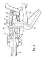
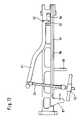
- FIG. 1shows an overall view of the instrument
- FIG. 2shows a view of the front section of the instrument, on an enlarged scale
- FIG. 3shows a view corresponding to FIG. 2 , with withdrawal forceps applied
- FIG. 4shows a view corresponding to FIG. 3 , seen in a vertical direction
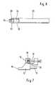
- FIG. 5shows the withdrawal forceps
- FIG. 6shows a partial view of the withdrawal forceps, seen from the direction A in FIG. 5 .
- FIG. 7shows a detail of the slide
- FIG. 8shows the overall view of a second instrument
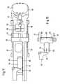
- FIG. 9shows a perspective view of the front section of this instrument
- FIG. 10shows a side view of the front section
- FIG. 11shows a bottom view of the front section
- FIG. 12shows a bottom view of the rear section
- FIG. 13shows a detail of the actuating device.
- the instrument shown in FIGS. 1 to 7is an expansion forceps with hand levers 1 and with working clamps 2 which are guided in parallel and each have a prosthesis holder 3 at their front ends.
- the prosthesis holders 3are designed in a U-shape with two side branches 4 . They each receive the side edges of a respective prosthesis plate 5 in slide grooves.
- the view in FIG. 4is directed towards the outside of a prosthesis plate 5 which is intended to bear on a vertebral body and has teeth 6 for better connection thereto.
- the prosthesis holderis designed in such a way that the prosthesis can be removed in arrow direction 7 with sufficient ease. It is secured against inadvertent release by means of a spring 8 .
- EP-B-333990For details of the design and use, reference may be made to EP-B-333990.
- the prosthesis holder 3forms a central guide groove 10 which is arranged in the same direction and to which a bore 11 is contiguous towards the rear in the same direction.
- the groove 10receives a slide 12 which can slide easily therein in the groove direction but which is guided securely and connected to a rod 13 which is guided through the bore 11 and rearward from the latter.
- the slide 12can be displaced in the longitudinal direction in the groove 10 , as can be seen from the different adjustment of the lower and upper slides in FIG. 2 .
- the slide 12forms a prosthesis limit stop 15 and a vertebral limit stop 16 which, in relation to the latter, is set back slightly, which limit stops are connected securely to one another in the example shown.
- the prosthesis limit stop 15lies flush with the rear edge 17 of the space provided for receiving the prosthesis 5 .
- the instrumentis introduced into the intervertebral space until the vertebral limit stop bears on the ventral margin of the vertebra in question.
- the spacing between the limit stops 15 and 16thus determines the depth of insertion of the prosthesis. If the part 18 forming the vertebral limit stop 16 is made displaceable on the slide 12 , the depth of insertion of the prosthesis can be predetermined variably.
- FIG. 7shows a slide 12 on which the vertebral limit stop 16 is formed by a separate block 19 which can be displaced in relation to the prosthesis limit stop 15 by means of a threaded spindle 31 .
- an adjustment scale 32is provided on the slide 12 . In the example shown, it cooperates with a rear edge of the vertebral limit stop 16 acting as indicator. Scale and indicator can also be arranged in another way, for example the marking on a side face of the vertebral limit stop 16 and the scale on an upper face of the prosthesis guide 3 .
- the prosthesis limit stoppushes the prosthesis out of the prosthesis holder when the slide is advanced.
- the instrumentis thereby withdrawn from the prosthesis.
- the rods 13must be pushed forwards in relation to the instrument. This is done using the withdrawal forceps shown in FIG. 5 , which forceps can be easily connected to the instrument.
- Its grip branches 20 spread apart via a springmerge into working levers 22 , 23 beyond the hinge point 21 , which working levers 22 , 23 extend substantially transverse to the direction of the grip branches 20 .
- the working lever 22includes a receiving opening 24 which is demarcated in a U-shape and whose width is slightly greater than the diameter of a pin 25 on a bracket 26 which is arranged on the instrument in such a way that it is arranged approximately centrally in relation to the rods 13 independently of the respective spreading of the prosthesis holders 3 .
- a rocker 28Arranged on the front working lever 23 there is a rocker 28 which can pivot about an axis 27 .
- the pivot point 27lies approximately in the direction of the centre axis of the pin 25 when the withdrawal forceps is applied to the instrument ( FIG. 3 ).
- the side of the rocker 28 directed away from the pin 25includes a groove 29 whose width is slightly greater than the diameter of the rods 13 at their rear ends.
- the working lever 23moves forwards in relation to the bracket 26 supporting the working lever 22 , so that the rods 13 and thus the slides 12 are moved forwards via the rocker 28 .
- the prosthesis plates situated in the prosthesis holderare pushed forwards out of the guide or, to put it another way, the instrument is withdrawn from the prosthesis.
- Part of the withdrawal forceis also transmitted to the vertebrae via the vertebral limit stops 16 . If this is not desirable, the vertebral limit stops 16 can be set back slightly by means of the adjustment device after the prosthesis has been positioned and immediately before the instrument is withdrawn, so that said vertebral limit stops 16 no longer bear on the vertebrae. The vertebrae then remain free from forces during withdrawal.
- FIGS. 8 to 12show an alternative embodiment.
- the prosthesis holders 52are fork-shaped and open at the end. Their side branches form guides for the edge of the prosthesis plates 53 . They make it possible, by overcoming a frictional force, to insert the prosthesis plates into the prosthesis holders 52 , and remove them from said prosthesis holders 52 , in the longitudinal direction of the instrument.
- the prosthesis body 51has a strike plate 54 . By striking this plate, the prosthesis plates 53 held by the prosthesis holders 52 can be driven between two vertebrae.
- the lower of the prosthesis holders 52( FIGS. 9 and 10 ) is securely connected to the instrument body 51 and, in the example shown, even made integral therewith.
- the upper prosthesis holder 52is connected to the instrument body 51 via a scissor arrangement consisting of scissor members 56 , 57 .
- the scissor arrangement 56 , 57is designed in such a way that the upper prosthesis holder 52 can move exclusively perpendicular to the lower prosthesis holder 52 and parallel to it.
- the prosthesis holderscan be brought as close as possible to one another ( FIG. 1 ) so that it is easier to drive them into the intervertebral space. They can be spread apart together with the adjoining vertebrae ( FIGS. 9 and 10 ) in order to create space for introducing the prosthesis core between the prosthesis plates 53 . They are then brought back towards each other in order to secure the prosthesis core in the desired position. The instrument can then be removed.
- the rear pins 58 , 59 of the scissor members 56 , 57slide in oblong holes in the instrument body 51 , their direction corresponding to the longitudinal direction of the instrument, whereas the front pins 60 are connected rigidly to the prosthesis holders 52 .
- a deviceis provided which moves the rear pin 58 of the scissor member 57 in the longitudinal direction of the instrument.
- the grip lever 61is provided which can pivot on the instrument body about an axis 62 and has a working lever 63 which acts on the rear end of a slide block 64 which is part of a T-shaped carriage 65 ( FIG.
- the rear end of the scissor member 57is driven forwards, as a result of which the prosthesis holders 52 are spread apart.
- the working lever 63 , the carriage 65 and the oblique connectors 57thus form an arrangement for adjusting the spacing of the prosthesis holders 52 . It will be appreciated that this arrangement can also be replaced by other embodiments. It will further be seen that the spreading force does not necessarily have to be exerted via the oblique connectors 57 . If the angle between the oblique connector 57 and the longitudinal direction of the instrument is too small for exerting a substantial spreading force, a separate member can be provided for the spreading.
- the hand lever 61is supplemented with a threaded spindle 71 with a butterfly nut 72 , which makes the procedure easier and makes it possible to temporarily hold the instrument in the spread position.
- a channel-like free spaceis formed between the instrument body 51 and the plate 53 continuing the upper prosthesis holder 52 rearwards, on the one hand, and between the lateral scissor arrangements 56 , 57 on the other hand.
- the prosthesis core 77can be guided through this free space between the prosthesis plates 52 ( FIG. 10 ).
- the instrument 76has a limit stop 75 which bears on the rear edge 74 of the plate 73 when the prosthesis core 77 has exactly reached the intended position between the prosthesis plates 52 .
- the prosthesis holders 52include, behind the space for receiving the prosthesis plates 53 , a guide groove 80 which extends in the longitudinal direction of the instrument and thus in the direction of sliding of the prosthesis holders 52 . It includes a slide 81 whose front end 82 strikes against the edge of the prosthesis plate located in the prosthesis holder and is for this reason referred to as a prosthesis limit stop.
- the rear end of the slide 81is rigidly connected to a rod 83 which is likewise guided in the longitudinal direction of the instrument. As is shown in FIG.
- the rear end of the rod 83 mounted in the instrument body 51is secured on a limit stop element 84 , the nature of which will be explained below. It is likewise displaceable in the longitudinal direction of the instrument.
- the limit stop element 84is in turn rigidly connected to a push rod 86 which is mounted so as to be longitudinally displaceable in the instrument body 51 and (see FIG. 12 ) leads to a handle 87 .
- the push rod 86 , the limit stop element 84 , the rod 83 and the slide 81are pushed forwards, so as to push the prosthesis plate 53 out of the prosthesis holder 52 .
- the hand of the operating surgeoncan rest on a journal 88 ( FIG. 12 ) which is connected securely to the instrument body 51 .
- the movement of the handle 87acts directly only on the slide 81 which is arranged in the lower part of the instrument, namely in the instrument body.
- a movement-transmitting deviceis provided.
- the rod 83 controlling the slide 81 of the upper prosthesis holderis securely connected at its rear end to a limit stop element 85 which, like the limit stop element 84 of the lower prosthesis holder, is guided movably in the longitudinal direction of the instrument.
- the lower limit stop element 84has, on both sides, upwardly protruding limit stop branches 90 which lie behind and adjacent to the branches 91 which protrude downwards on both sides from the upper limit stop element 85 .
- the mutually adjacent end faces of the limit stop branches 90 , 91also bear on one another. If, by actuating the handle 87 , the lower limit stop element 84 with the limit stop branches 90 is now pushed forwards, their cooperation with the limit stop branches 91 of the upper limit stop element means that the slide 81 of the upper prosthesis holder is pushed forwards too. The two slides 81 thus move in synchrony. Since the interacting limit stop surfaces 90 , 91 are perpendicular to the longitudinal direction of the instrument, the synchronous movement of the slides 81 is guaranteed independently of the respective spacing of the prosthesis holders from each other.
- Each slide 81has an attachment 95 rigidly connected to it, and a block 96 which is guided in the longitudinal direction of the slide and whose end face forms the vertebral limit stop. If the prosthesis holders with the prosthesis plates 53 located therein are driven into the space between two vertebrae, the end faces of the vertebral limit stops 96 finally bear on the ventral margins of the vertebral bodies. The spacing of the end faces of the vertebral limit stops 96 from the prosthesis plates thus defines the depth at which the prosthesis plates arrive in the intervertebral space. This depth can be changed by adjusting the vertebral limit stops 96 on the slides 81 .
Landscapes
- Health & Medical Sciences (AREA)
- Engineering & Computer Science (AREA)
- Biomedical Technology (AREA)
- Orthopedic Medicine & Surgery (AREA)
- Life Sciences & Earth Sciences (AREA)
- Transplantation (AREA)
- Veterinary Medicine (AREA)
- Public Health (AREA)
- General Health & Medical Sciences (AREA)
- Heart & Thoracic Surgery (AREA)
- Animal Behavior & Ethology (AREA)
- Physical Education & Sports Medicine (AREA)
- Vascular Medicine (AREA)
- Oral & Maxillofacial Surgery (AREA)
- Cardiology (AREA)
- Neurology (AREA)
- Surgery (AREA)
- Nuclear Medicine, Radiotherapy & Molecular Imaging (AREA)
- Medical Informatics (AREA)
- Molecular Biology (AREA)
- Prostheses (AREA)
- Surgical Instruments (AREA)
Abstract
Description
Claims (14)
Applications Claiming Priority (5)
| Application Number | Priority Date | Filing Date | Title |
|---|---|---|---|
| EP011007549 | 2001-01-12 | ||
| EP01100754 | 2001-01-12 | ||
| EP01125792AEP1222903B1 (en) | 2001-01-12 | 2001-10-29 | Surgical instrument for implanting an intervertebral prosthesis |
| EP011257920 | 2001-10-29 | ||
| PCT/EP2001/015357WO2002054994A1 (en) | 2001-01-12 | 2001-12-28 | Surgical instrument for inserting an intervertebral endoprosthesis |
Publications (2)
| Publication Number | Publication Date |
|---|---|
| US20040220582A1 US20040220582A1 (en) | 2004-11-04 |
| US7387635B2true US7387635B2 (en) | 2008-06-17 |
Family
ID=26076439
Family Applications (1)
| Application Number | Title | Priority Date | Filing Date |
|---|---|---|---|
| US10/363,164Expired - LifetimeUS7387635B2 (en) | 2001-01-12 | 2001-12-28 | Surgical instrument for inserting an intervertebral endoprosthesis |
Country Status (14)
| Country | Link |
|---|---|
| US (1) | US7387635B2 (en) |
| EP (1) | EP1222903B1 (en) |
| JP (1) | JP2004516907A (en) |
| KR (1) | KR20030076608A (en) |
| CN (1) | CN1486167A (en) |
| AR (1) | AR033414A1 (en) |
| BR (1) | BR0116743A (en) |
| CA (1) | CA2421153A1 (en) |
| CZ (1) | CZ2003559A3 (en) |
| IL (1) | IL154640A0 (en) |
| MX (1) | MXPA03002524A (en) |
| PL (1) | PL361913A1 (en) |
| RU (1) | RU2003124750A (en) |
| WO (1) | WO2002054994A1 (en) |
Cited By (30)
| Publication number | Priority date | Publication date | Assignee | Title |
|---|---|---|---|---|
| US20060085011A1 (en)* | 2004-10-15 | 2006-04-20 | Zimmer Gmbh | Instrument system for the insertion of intervertebral disk implants |
| US20060293625A1 (en)* | 2003-12-19 | 2006-12-28 | Hunt John V | Implantable medical device with cover and method |
| US20070010790A1 (en)* | 2005-06-24 | 2007-01-11 | Byrum Randal T | Injection port |
| US20070078464A1 (en)* | 2005-09-30 | 2007-04-05 | Depuy Products, Inc. | Separator tool for a modular prosthesis |
| US20070149947A1 (en)* | 2003-12-19 | 2007-06-28 | Byrum Randal T | Audible and tactile feedback |
| US20070198025A1 (en)* | 2000-08-30 | 2007-08-23 | Trieu Hai H | Method and apparatus for delivering an intervertebral disc implant |
| US20090030421A1 (en)* | 2007-07-23 | 2009-01-29 | Depuy Spine, Inc. | Implant engagement method and device |
| US20090112219A1 (en)* | 2007-10-31 | 2009-04-30 | Daniels David W | Taper sleeve extractor |
| US20090112216A1 (en)* | 2007-10-30 | 2009-04-30 | Leisinger Steven R | Taper disengagement tool |
| US20090164017A1 (en)* | 2007-12-19 | 2009-06-25 | Robert Sommerich | Expandable Corpectomy Spinal Fusion Cage |
| US20090164018A1 (en)* | 2007-12-19 | 2009-06-25 | Robert Sommerich | Instruments For Expandable Corpectomy Spinal Fusion Cage |
| US7561916B2 (en) | 2005-06-24 | 2009-07-14 | Ethicon Endo-Surgery, Inc. | Implantable medical device with indicator |
| US20100130941A1 (en)* | 2003-06-16 | 2010-05-27 | Conlon Sean P | Audible And Tactile Feedback |
| US20100234808A1 (en)* | 2003-06-16 | 2010-09-16 | Uth Joshua R | Injection Port Applier with Downward Force Actuation |
| US20100280616A1 (en)* | 2009-04-29 | 2010-11-04 | William Frasier | Minimally invasive corpectomy cage and instrument |
| US7918844B2 (en) | 2005-06-24 | 2011-04-05 | Ethicon Endo-Surgery, Inc. | Applier for implantable medical device |
| US20110190820A1 (en)* | 2008-05-28 | 2011-08-04 | Erik Johansson | Displacement Device, Use and System Therefore |
| US20120310293A1 (en)* | 2008-10-16 | 2012-12-06 | Aesculap Implant Systems, Llc. | Surgical instrument and method of use for inserting an implant between two bones |
| US8500749B2 (en)* | 2011-04-19 | 2013-08-06 | Prescient Surgical Designs, Llc | Apparatus and method for inserting intervertebral implants |
| US8562681B2 (en) | 2012-01-31 | 2013-10-22 | Styker Spine | Laminoplasty implant, method and instrumentation |
| US8685036B2 (en) | 2003-06-25 | 2014-04-01 | Michael C. Jones | Assembly tool for modular implants and associated method |
| US8998906B2 (en) | 2012-07-09 | 2015-04-07 | X-Spine Systems, Inc. | Surgical implant inserter compressor |
| US9034046B2 (en) | 2007-10-30 | 2015-05-19 | Aesculap Implant Systems, Llc | Vertebral body replacement device and method for use to maintain a space between two vertebral bodies within a spine |
| US9095452B2 (en) | 2010-09-01 | 2015-08-04 | DePuy Synthes Products, Inc. | Disassembly tool |
| US9101495B2 (en) | 2010-06-15 | 2015-08-11 | DePuy Synthes Products, Inc. | Spiral assembly tool |
| US9119601B2 (en) | 2007-10-31 | 2015-09-01 | DePuy Synthes Products, Inc. | Modular taper assembly device |
| US9381097B2 (en) | 2003-06-25 | 2016-07-05 | DePuy Synthes Products, Inc. | Assembly tool for modular implants, kit and associated method |
| US9504578B2 (en) | 2011-04-06 | 2016-11-29 | Depuy Synthes Products, Inc | Revision hip prosthesis having an implantable distal stem component |
| US10952714B1 (en) | 2017-07-14 | 2021-03-23 | OrtoWay AB | Apparatus, methods and systems for spine surgery |
| US11957598B2 (en) | 2004-02-04 | 2024-04-16 | Ldr Medical | Intervertebral disc prosthesis |
Families Citing this family (88)
| Publication number | Priority date | Publication date | Assignee | Title |
|---|---|---|---|---|
| US6673113B2 (en) | 2001-10-18 | 2004-01-06 | Spinecore, Inc. | Intervertebral spacer device having arch shaped spring elements |
| US7169182B2 (en)* | 2001-07-16 | 2007-01-30 | Spinecore, Inc. | Implanting an artificial intervertebral disc |
| FR2824261B1 (en) | 2001-05-04 | 2004-05-28 | Ldr Medical | INTERVERTEBRAL DISC PROSTHESIS AND IMPLEMENTATION METHOD AND TOOLS |
| US7713302B2 (en) | 2001-10-01 | 2010-05-11 | Spinecore, Inc. | Intervertebral spacer device utilizing a spirally slotted belleville washer having radially spaced concentric grooves |
| US7771477B2 (en) | 2001-10-01 | 2010-08-10 | Spinecore, Inc. | Intervertebral spacer device utilizing a belleville washer having radially spaced concentric grooves |
| FR2836373B1 (en) | 2002-02-26 | 2005-03-25 | Materiel Orthopedique En Abreg | CONNECTING INTERSOMATIC IMPLANTS FOR INSERTING BONE GRAFT FOR REALIZING INTERVERTEBRAL FUSION, INSTRUMENTS FOR CONNECTING THESE IMPLANTS |
| US8038713B2 (en) | 2002-04-23 | 2011-10-18 | Spinecore, Inc. | Two-component artificial disc replacements |
| US20080027548A9 (en) | 2002-04-12 | 2008-01-31 | Ferree Bret A | Spacerless artificial disc replacements |
| AU2003234508A1 (en)* | 2002-05-06 | 2003-11-17 | Warsaw Orthopedic, Inc. | Instrumentation and methods for preparation of an intervertebral space |
| ATE381295T1 (en) | 2002-05-21 | 2008-01-15 | Warsaw Orthopedic Inc | DEVICE FOR DISTRACTING BONE SEGMENTS |
| EP1542626B1 (en) | 2002-08-15 | 2012-09-26 | Synthes GmbH | Controlled artificial intervertebral disc implant |
| CA2495404C (en) | 2002-08-15 | 2011-05-03 | Justin K. Coppes | Intervertebral disc implant |
| JP4654125B2 (en)* | 2002-10-29 | 2011-03-16 | スパインコア,インコーポレイテッド | Instruments, methods, and functions for use in implanting an artificial disc |
| FR2846550B1 (en) | 2002-11-05 | 2006-01-13 | Ldr Medical | INTERVERTEBRAL DISC PROSTHESIS |
| FR2850563B1 (en)* | 2003-02-05 | 2005-11-04 | Scient X | VERTEBRAL REPLACEMENT IMPLANT AND DISTRACTION APPARATUS FOR IMPLANT PLACEMENT |
| US6908484B2 (en) | 2003-03-06 | 2005-06-21 | Spinecore, Inc. | Cervical disc replacement |
| US7105024B2 (en) | 2003-05-06 | 2006-09-12 | Aesculap Ii, Inc. | Artificial intervertebral disc |
| US7291173B2 (en) | 2003-05-06 | 2007-11-06 | Aesculap Ii, Inc. | Artificial intervertebral disc |
| DE10324108B3 (en)* | 2003-05-21 | 2005-01-27 | Aesculap Ag & Co. Kg | Backbone implant is inserted with contracted contact disc which is expanded to optimum area following insertion |
| DE10330698B4 (en) | 2003-07-08 | 2005-05-25 | Aesculap Ag & Co. Kg | Intervertebral implant |
| DE20310433U1 (en)* | 2003-07-08 | 2003-09-04 | Aesculap AG & Co. KG, 78532 Tuttlingen | Surgical device for inserting dual component implant into appropriate space at spine, comprising particularly shaped holding area |
| US7811329B2 (en) | 2003-07-31 | 2010-10-12 | Globus Medical | Transforaminal prosthetic spinal disc replacement and methods thereof |
| US7713304B2 (en) | 2003-07-31 | 2010-05-11 | Globus Medical, Inc. | Transforaminal prosthetic spinal disc replacement |
| US7621956B2 (en)* | 2003-07-31 | 2009-11-24 | Globus Medical, Inc. | Prosthetic spinal disc replacement |
| DE10339170B4 (en) | 2003-08-22 | 2009-10-15 | Aesculap Ag | Intervertebral implant |
| FR2865629B1 (en) | 2004-02-04 | 2007-01-26 | Ldr Medical | INTERVERTEBRAL DISC PROSTHESIS |
| FR2869528B1 (en) | 2004-04-28 | 2007-02-02 | Ldr Medical | INTERVERTEBRAL DISC PROSTHESIS |
| DE202004009542U1 (en) | 2004-06-16 | 2004-08-12 | Aesculap Ag & Co. Kg | Artificial intervertebral disk, comprising core with intensely curved upper and less curved lower surface |
| US7294134B2 (en)* | 2004-07-28 | 2007-11-13 | Weber Instrumente Gmbh | Surgical instrument for the introduction of a multi-component intervertebral prosthesis |
| JP2006068086A (en)* | 2004-08-31 | 2006-03-16 | Takiron Co Ltd | Artificial spinal disk insertion tool and tool set |
| DE102004043995A1 (en) | 2004-09-08 | 2006-03-30 | Aesculap Ag & Co. Kg | Surgical instrument |
| WO2006058221A2 (en) | 2004-11-24 | 2006-06-01 | Abdou Samy M | Devices and methods for inter-vertebral orthopedic device placement |
| FR2879436B1 (en) | 2004-12-22 | 2007-03-09 | Ldr Medical | INTERVERTEBRAL DISC PROSTHESIS |
| US7722622B2 (en)* | 2005-02-25 | 2010-05-25 | Synthes Usa, Llc | Implant insertion apparatus and method of use |
| US8777959B2 (en) | 2005-05-27 | 2014-07-15 | Spinecore, Inc. | Intervertebral disc and insertion methods therefor |
| FR2887762B1 (en)* | 2005-06-29 | 2007-10-12 | Ldr Medical Soc Par Actions Si | INTERVERTEBRAL DISC PROSTHESIS INSERTION INSTRUMENTATION BETWEEN VERTEBRATES |
| CA2621019A1 (en)* | 2005-08-31 | 2007-03-08 | Zimmer Gmbh | Implant |
| FR2891135B1 (en) | 2005-09-23 | 2008-09-12 | Ldr Medical Sarl | INTERVERTEBRAL DISC PROSTHESIS |
| US7618459B2 (en)* | 2005-09-26 | 2009-11-17 | Infinity Orthopedics Ltd. | Universal spinal disc implant system |
| EP1772106A1 (en) | 2005-10-06 | 2007-04-11 | Zimmer GmbH | Instrument for preparing and/or working the femur head |
| EP1973498B1 (en)* | 2005-11-09 | 2014-04-23 | Zimmer GmbH | Implant |
| FR2893838B1 (en) | 2005-11-30 | 2008-08-08 | Ldr Medical Soc Par Actions Si | PROSTHESIS OF INTERVERTEBRAL DISC AND INSTRUMENTATION OF INSERTION OF THE PROSTHESIS BETWEEN VERTEBRATES |
| WO2007090790A2 (en)* | 2006-02-09 | 2007-08-16 | Zimmer Gmbh | Implant |
| US7918889B2 (en)* | 2006-02-27 | 2011-04-05 | Warsaw Orthopedic, Inc. | Expandable spinal prosthetic devices and associated methods |
| US8066714B2 (en)* | 2006-03-17 | 2011-11-29 | Warsaw Orthopedic Inc. | Instrumentation for distraction and insertion of implants in a spinal disc space |
| US7806901B2 (en)* | 2006-03-17 | 2010-10-05 | Depuy Spine, Inc. | Arthroplasty final seating instruments |
| WO2007125060A1 (en)* | 2006-04-28 | 2007-11-08 | Zimmer Gmbh | Implant |
| US8303601B2 (en) | 2006-06-07 | 2012-11-06 | Stryker Spine | Collet-activated distraction wedge inserter |
| US8062303B2 (en)* | 2006-08-16 | 2011-11-22 | K2M, Inc. | Apparatus and methods for inserting an implant |
| US9381098B2 (en)* | 2006-09-28 | 2016-07-05 | Spinal Kinetics, Inc. | Tool systems for implanting prosthetic intervertebral discs |
| US8974496B2 (en)* | 2007-08-30 | 2015-03-10 | Jeffrey Chun Wang | Interspinous implant, tools and methods of implanting |
| US8465546B2 (en)* | 2007-02-16 | 2013-06-18 | Ldr Medical | Intervertebral disc prosthesis insertion assemblies |
| US8361080B2 (en)* | 2007-03-30 | 2013-01-29 | Depuy Spine, Inc. | Implant inserter having a bifurcated adjustable stop |
| FR2916956B1 (en) | 2007-06-08 | 2012-12-14 | Ldr Medical | INTERSOMATIC CAGE, INTERVERTEBRAL PROSTHESIS, ANCHORING DEVICE AND IMPLANTATION INSTRUMENTATION |
| US8486081B2 (en) | 2007-07-23 | 2013-07-16 | DePuy Synthes Products, LLC | Implant insertion device and method |
| WO2009018128A2 (en)* | 2007-07-31 | 2009-02-05 | Zimmer, Inc. | Joint space interpositional prosthetic device with internal bearing surfaces |
| US8801758B2 (en) | 2007-08-13 | 2014-08-12 | Stryker Spine | Insertion instrument for intervertebral implants |
| AU2009205679B2 (en) | 2008-01-18 | 2013-12-05 | Spinecore, Inc. | Instruments and methods for inserting artificial intervertebral implants |
| US8147499B2 (en) | 2008-04-24 | 2012-04-03 | Spinecore, Inc. | Dynamic distractor |
| EP2337510B1 (en) | 2008-06-25 | 2018-10-31 | Stryker European Holdings I, LLC | Surgical instrumentation for implanting a prothesis |
| US9095450B2 (en)* | 2008-12-24 | 2015-08-04 | DePuy Syntheses Products, Inc. | Insertion instrument for anteriorly inserting intervertebral spinal implants |
| CN101991457B (en)* | 2009-08-27 | 2012-12-19 | 邹德威 | Interfacial distracting device of cervical vertebra facet joint |
| US8277509B2 (en) | 2009-12-07 | 2012-10-02 | Globus Medical, Inc. | Transforaminal prosthetic spinal disc apparatus |
| US8764806B2 (en) | 2009-12-07 | 2014-07-01 | Samy Abdou | Devices and methods for minimally invasive spinal stabilization and instrumentation |
| US8465547B2 (en)* | 2010-01-27 | 2013-06-18 | Warsaw Orthopedic, Inc. | Modular interbody devices and methods of use |
| US9585672B2 (en) | 2011-02-25 | 2017-03-07 | Thd S.P.A. | Device for implanting a prosthesis in a tissue |
| US9265620B2 (en) | 2011-03-18 | 2016-02-23 | Raed M. Ali, M.D., Inc. | Devices and methods for transpedicular stabilization of the spine |
| EP2685921B1 (en) | 2011-03-18 | 2019-03-13 | Raed M. Ali, M.D., Inc. | Transpedicular access to intervertebral spaces and related spinal fusion systems and methods |
| US8845728B1 (en) | 2011-09-23 | 2014-09-30 | Samy Abdou | Spinal fixation devices and methods of use |
| US9017410B2 (en) | 2011-10-26 | 2015-04-28 | Globus Medical, Inc. | Artificial discs |
| US20130226240A1 (en) | 2012-02-22 | 2013-08-29 | Samy Abdou | Spinous process fixation devices and methods of use |
| US9198767B2 (en) | 2012-08-28 | 2015-12-01 | Samy Abdou | Devices and methods for spinal stabilization and instrumentation |
| US9320617B2 (en) | 2012-10-22 | 2016-04-26 | Cogent Spine, LLC | Devices and methods for spinal stabilization and instrumentation |
| US10687962B2 (en) | 2013-03-14 | 2020-06-23 | Raed M. Ali, M.D., Inc. | Interbody fusion devices, systems and methods |
| US9301849B2 (en)* | 2013-03-14 | 2016-04-05 | Warsaw Orthopedic, Inc. | Endplate punch template and method of use |
| US9861495B2 (en) | 2013-03-14 | 2018-01-09 | Raed M. Ali, M.D., Inc. | Lateral interbody fusion devices, systems and methods |
| US9198770B2 (en) | 2013-07-31 | 2015-12-01 | Globus Medical, Inc. | Artificial disc devices and related methods of use |
| DE102014102606A1 (en)* | 2014-02-27 | 2015-08-27 | Aesculap Ag | Microsurgical holding and / or cutting instrument |
| US10857003B1 (en) | 2015-10-14 | 2020-12-08 | Samy Abdou | Devices and methods for vertebral stabilization |
| US10543004B2 (en)* | 2015-12-23 | 2020-01-28 | Osteomed Llc | Bone centering drill guide |
| US10973648B1 (en) | 2016-10-25 | 2021-04-13 | Samy Abdou | Devices and methods for vertebral bone realignment |
| US10744000B1 (en) | 2016-10-25 | 2020-08-18 | Samy Abdou | Devices and methods for vertebral bone realignment |
| US11013607B2 (en) | 2017-09-22 | 2021-05-25 | Encore Medical, L.P. | Talar ankle implant |
| EP3501432A1 (en) | 2017-12-20 | 2019-06-26 | Stryker European Holdings I, LLC | Joint instrumentation |
| US11179248B2 (en) | 2018-10-02 | 2021-11-23 | Samy Abdou | Devices and methods for spinal implantation |
| KR102096339B1 (en) | 2019-11-06 | 2020-04-02 | 의료법인 명지의료재단 | Glenosphere Insertion Instrument With Adjustable Angle |
| CN112568986B (en)* | 2020-12-29 | 2022-04-12 | 北京爱康宜诚医疗器材有限公司 | Vertebral plate distraction and prosthesis implantation device |
| US20250160992A1 (en)* | 2023-11-17 | 2025-05-22 | Globus Medical, Inc. | Implant load feedback apparatus |
Citations (10)
| Publication number | Priority date | Publication date | Assignee | Title |
|---|---|---|---|---|
| US3486505A (en) | 1967-05-22 | 1969-12-30 | Gordon M Morrison | Orthopedic surgical instrument |
| EP0077159A1 (en) | 1981-10-14 | 1983-04-20 | Brian Norman Atkins | Vertebrae spreader |
| EP0333990A2 (en) | 1988-03-23 | 1989-09-27 | Waldemar Link (GmbH & Co.) | Surgical instrument set |
| US5364397A (en)* | 1993-06-01 | 1994-11-15 | Zimmer, Inc. | Spinal coupler seater with dual jaws and an independent plunger |
| US5431658A (en) | 1994-02-14 | 1995-07-11 | Moskovich; Ronald | Facilitator for vertebrae grafts and prostheses |
| FR2737656A1 (en) | 1995-08-09 | 1997-02-14 | Jbs Sa | IMPACTOR DEVICE FOR PLACING A PROSTHESIS FOR INTERVERTEBRAL DISCS |
| DE29916078U1 (en) | 1999-09-14 | 1999-11-25 | Aesculap Ag & Co Kg | Insertion tool for an intervertebral implant |
| DE20012549U1 (en) | 2000-07-20 | 2000-10-12 | Aesculap AG & Co. KG, 78532 Tuttlingen | Insertion tool for an intervertebral implant |
| US6159215A (en)* | 1997-12-19 | 2000-12-12 | Depuy Acromed, Inc. | Insertion instruments and method for delivering a vertebral body spacer |
| US6478800B1 (en)* | 2000-05-08 | 2002-11-12 | Depuy Acromed, Inc. | Medical installation tool |
- 2001
- 2001-10-29EPEP01125792Apatent/EP1222903B1/ennot_activeExpired - Lifetime
- 2001-12-28JPJP2002555732Apatent/JP2004516907A/enactivePending
- 2001-12-28PLPL01361913Apatent/PL361913A1/enunknown
- 2001-12-28CZCZ2003559Apatent/CZ2003559A3/enunknown
- 2001-12-28USUS10/363,164patent/US7387635B2/ennot_activeExpired - Lifetime
- 2001-12-28CACA002421153Apatent/CA2421153A1/ennot_activeAbandoned
- 2001-12-28KRKR10-2003-7009269Apatent/KR20030076608A/ennot_activeCeased
- 2001-12-28WOPCT/EP2001/015357patent/WO2002054994A1/ennot_activeApplication Discontinuation
- 2001-12-28CNCNA018219187Apatent/CN1486167A/enactivePending
- 2001-12-28RURU2003124750/14Apatent/RU2003124750A/ennot_activeApplication Discontinuation
- 2001-12-28ILIL15464001Apatent/IL154640A0/enunknown
- 2001-12-28MXMXPA03002524Apatent/MXPA03002524A/enunknown
- 2001-12-28BRBR0116743-0Apatent/BR0116743A/ennot_activeApplication Discontinuation
- 2002
- 2002-01-11ARARP020100097Apatent/AR033414A1/enunknown
Patent Citations (10)
| Publication number | Priority date | Publication date | Assignee | Title |
|---|---|---|---|---|
| US3486505A (en) | 1967-05-22 | 1969-12-30 | Gordon M Morrison | Orthopedic surgical instrument |
| EP0077159A1 (en) | 1981-10-14 | 1983-04-20 | Brian Norman Atkins | Vertebrae spreader |
| EP0333990A2 (en) | 1988-03-23 | 1989-09-27 | Waldemar Link (GmbH & Co.) | Surgical instrument set |
| US5364397A (en)* | 1993-06-01 | 1994-11-15 | Zimmer, Inc. | Spinal coupler seater with dual jaws and an independent plunger |
| US5431658A (en) | 1994-02-14 | 1995-07-11 | Moskovich; Ronald | Facilitator for vertebrae grafts and prostheses |
| FR2737656A1 (en) | 1995-08-09 | 1997-02-14 | Jbs Sa | IMPACTOR DEVICE FOR PLACING A PROSTHESIS FOR INTERVERTEBRAL DISCS |
| US6159215A (en)* | 1997-12-19 | 2000-12-12 | Depuy Acromed, Inc. | Insertion instruments and method for delivering a vertebral body spacer |
| DE29916078U1 (en) | 1999-09-14 | 1999-11-25 | Aesculap Ag & Co Kg | Insertion tool for an intervertebral implant |
| US6478800B1 (en)* | 2000-05-08 | 2002-11-12 | Depuy Acromed, Inc. | Medical installation tool |
| DE20012549U1 (en) | 2000-07-20 | 2000-10-12 | Aesculap AG & Co. KG, 78532 Tuttlingen | Insertion tool for an intervertebral implant |
Cited By (70)
| Publication number | Priority date | Publication date | Assignee | Title |
|---|---|---|---|---|
| US20070198025A1 (en)* | 2000-08-30 | 2007-08-23 | Trieu Hai H | Method and apparatus for delivering an intervertebral disc implant |
| US7857818B2 (en)* | 2000-08-30 | 2010-12-28 | Warsaw Orthopedic, Inc. | Method and apparatus for delivering an intervertebral disc implant |
| US8715243B2 (en) | 2003-06-16 | 2014-05-06 | Ethicon Endo-Surgery, Inc. | Injection port applier with downward force actuation |
| US8764713B2 (en) | 2003-06-16 | 2014-07-01 | Ethicon Endo-Surgery, Inc. | Method of repositioning an injection port |
| US8758303B2 (en) | 2003-06-16 | 2014-06-24 | Ethicon Endo-Surgery, Inc. | Injection port with applier |
| US8864717B2 (en) | 2003-06-16 | 2014-10-21 | Ethicon Endo-Surgery, Inc. | Subcutaneous self attaching injection port with integral moveable retention members |
| US20100211085A1 (en)* | 2003-06-16 | 2010-08-19 | Ethicon Endo-Surgery, Inc. | Injection Port with Extendable and Retractable Fasteners |
| US8211127B2 (en) | 2003-06-16 | 2012-07-03 | Ethicon Endo-Surgery, Inc. | Injection port with extendable and retractable fasteners |
| US8007474B2 (en) | 2003-06-16 | 2011-08-30 | Ethicon Endo-Surgery, Inc. | Implantable medical device with reversible attachment mechanism and method |
| US20110082426A1 (en)* | 2003-06-16 | 2011-04-07 | Ethicon Endo-Surgery, Inc. | Subcutaneous self attaching injection port with integral moveable retention members |
| US20100234808A1 (en)* | 2003-06-16 | 2010-09-16 | Uth Joshua R | Injection Port Applier with Downward Force Actuation |
| US20100217199A1 (en)* | 2003-06-16 | 2010-08-26 | Ethicon Endo-Surgery, Inc. | Method of Repositioning an Injection Port |
| US20100130941A1 (en)* | 2003-06-16 | 2010-05-27 | Conlon Sean P | Audible And Tactile Feedback |
| US8685036B2 (en) | 2003-06-25 | 2014-04-01 | Michael C. Jones | Assembly tool for modular implants and associated method |
| US9381097B2 (en) | 2003-06-25 | 2016-07-05 | DePuy Synthes Products, Inc. | Assembly tool for modular implants, kit and associated method |
| US7553298B2 (en) | 2003-12-19 | 2009-06-30 | Ethicon Endo-Surgery, Inc. | Implantable medical device with cover and method |
| US20070149947A1 (en)* | 2003-12-19 | 2007-06-28 | Byrum Randal T | Audible and tactile feedback |
| US7850660B2 (en) | 2003-12-19 | 2010-12-14 | Ethicon Endo-Surgery, Inc. | Implantable medical device with simultaneous attachment mechanism and method |
| US20060293625A1 (en)* | 2003-12-19 | 2006-12-28 | Hunt John V | Implantable medical device with cover and method |
| US8162897B2 (en) | 2003-12-19 | 2012-04-24 | Ethicon Endo-Surgery, Inc. | Audible and tactile feedback |
| US11957598B2 (en) | 2004-02-04 | 2024-04-16 | Ldr Medical | Intervertebral disc prosthesis |
| US20060085011A1 (en)* | 2004-10-15 | 2006-04-20 | Zimmer Gmbh | Instrument system for the insertion of intervertebral disk implants |
| US20070010790A1 (en)* | 2005-06-24 | 2007-01-11 | Byrum Randal T | Injection port |
| US7651483B2 (en) | 2005-06-24 | 2010-01-26 | Ethicon Endo-Surgery, Inc. | Injection port |
| US7918844B2 (en) | 2005-06-24 | 2011-04-05 | Ethicon Endo-Surgery, Inc. | Applier for implantable medical device |
| US7561916B2 (en) | 2005-06-24 | 2009-07-14 | Ethicon Endo-Surgery, Inc. | Implantable medical device with indicator |
| US20070078464A1 (en)* | 2005-09-30 | 2007-04-05 | Depuy Products, Inc. | Separator tool for a modular prosthesis |
| US8152814B2 (en)* | 2005-09-30 | 2012-04-10 | Depuy Products, Inc. | Separator tool for a modular prosthesis |
| US20090030421A1 (en)* | 2007-07-23 | 2009-01-29 | Depuy Spine, Inc. | Implant engagement method and device |
| US10881527B2 (en) | 2007-10-30 | 2021-01-05 | Aesculap Implant Systems, Llc | Vertebral body replacement device and method for use to maintain a space between two vertebral bodies within a spine |
| US20090112216A1 (en)* | 2007-10-30 | 2009-04-30 | Leisinger Steven R | Taper disengagement tool |
| US10806595B2 (en) | 2007-10-30 | 2020-10-20 | Aesculap Implant Systems, Llc | Vertebral body replacement device and method for use to maintain a space between two vertebral bodies within a spine |
| US8556912B2 (en) | 2007-10-30 | 2013-10-15 | DePuy Synthes Products, LLC | Taper disengagement tool |
| US9717545B2 (en) | 2007-10-30 | 2017-08-01 | DePuy Synthes Products, Inc. | Taper disengagement tool |
| US9034046B2 (en) | 2007-10-30 | 2015-05-19 | Aesculap Implant Systems, Llc | Vertebral body replacement device and method for use to maintain a space between two vertebral bodies within a spine |
| US9119601B2 (en) | 2007-10-31 | 2015-09-01 | DePuy Synthes Products, Inc. | Modular taper assembly device |
| US20090112219A1 (en)* | 2007-10-31 | 2009-04-30 | Daniels David W | Taper sleeve extractor |
| US8241363B2 (en) | 2007-12-19 | 2012-08-14 | Depuy Spine, Inc. | Expandable corpectomy spinal fusion cage |
| US8241294B2 (en) | 2007-12-19 | 2012-08-14 | Depuy Spine, Inc. | Instruments for expandable corpectomy spinal fusion cage |
| US20090164017A1 (en)* | 2007-12-19 | 2009-06-25 | Robert Sommerich | Expandable Corpectomy Spinal Fusion Cage |
| US20090164018A1 (en)* | 2007-12-19 | 2009-06-25 | Robert Sommerich | Instruments For Expandable Corpectomy Spinal Fusion Cage |
| USRE46261E1 (en) | 2007-12-19 | 2017-01-03 | DePuy Synthes Products, Inc. | Instruments for expandable corpectomy spinal fusion cage |
| US8764800B2 (en)* | 2008-05-28 | 2014-07-01 | Ortoviva Ab | Displacement device, use and system therefore |
| US20110190820A1 (en)* | 2008-05-28 | 2011-08-04 | Erik Johansson | Displacement Device, Use and System Therefore |
| US8702719B2 (en)* | 2008-10-16 | 2014-04-22 | Aesculap Implant Systems, Llc | Surgical instrument and method of use for inserting an implant between two bones |
| US20120310293A1 (en)* | 2008-10-16 | 2012-12-06 | Aesculap Implant Systems, Llc. | Surgical instrument and method of use for inserting an implant between two bones |
| US20100280616A1 (en)* | 2009-04-29 | 2010-11-04 | William Frasier | Minimally invasive corpectomy cage and instrument |
| US8876905B2 (en) | 2009-04-29 | 2014-11-04 | DePuy Synthes Products, LLC | Minimally invasive corpectomy cage and instrument |
| US9101495B2 (en) | 2010-06-15 | 2015-08-11 | DePuy Synthes Products, Inc. | Spiral assembly tool |
| US10166118B2 (en) | 2010-06-15 | 2019-01-01 | DePuy Synthes Products, Inc. | Spiral assembly tool |
| US9095452B2 (en) | 2010-09-01 | 2015-08-04 | DePuy Synthes Products, Inc. | Disassembly tool |
| US10292837B2 (en) | 2010-09-01 | 2019-05-21 | Depuy Synthes Products Inc. | Disassembly tool |
| US9867720B2 (en) | 2010-09-01 | 2018-01-16 | DePuy Synthes Products, Inc. | Disassembly tool |
| US10888427B2 (en) | 2011-04-06 | 2021-01-12 | DePuy Synthes Products, Inc. | Distal reamer for use during an orthopaedic surgical procedure to implant a revision hip prosthesis |
| US9737405B2 (en) | 2011-04-06 | 2017-08-22 | DePuy Synthes Products, Inc. | Orthopaedic surgical procedure for implanting a revision hip prosthesis |
| US9949833B2 (en) | 2011-04-06 | 2018-04-24 | DePuy Synthes Products, Inc. | Finishing RASP and orthopaedic surgical procedure for using the same to implant a revision hip prosthesis |
| US10925739B2 (en) | 2011-04-06 | 2021-02-23 | DePuy Synthes Products, Inc. | Version-replicating instrument and orthopaedic surgical procedure for using the same to implant a revision hip prosthesis |
| US10064725B2 (en) | 2011-04-06 | 2018-09-04 | DePuy Synthes Products, Inc. | Distal reamer for use during an orthopaedic surgical procedure to implant a revision hip prosthesis |
| US9597188B2 (en) | 2011-04-06 | 2017-03-21 | DePuy Synthes Products, Inc. | Version-replicating instrument and orthopaedic surgical procedure for using the same to implant a revision hip prosthesis |
| US10226345B2 (en) | 2011-04-06 | 2019-03-12 | DePuy Synthes Products, Inc. | Version-replicating instrument and orthopaedic surgical procedure for using the same to implant a revision hip prosthesis |
| US9504578B2 (en) | 2011-04-06 | 2016-11-29 | Depuy Synthes Products, Inc | Revision hip prosthesis having an implantable distal stem component |
| US10603173B2 (en) | 2011-04-06 | 2020-03-31 | DePuy Synthes Products, Inc. | Orthopaedic surgical procedure for implanting a revision hip prosthesis |
| US10772730B2 (en) | 2011-04-06 | 2020-09-15 | DePuy Synthes Products, Inc. | Finishing rasp and orthopaedic surgical procedure for using the same to implant a revision hip prosthesis |
| US8500749B2 (en)* | 2011-04-19 | 2013-08-06 | Prescient Surgical Designs, Llc | Apparatus and method for inserting intervertebral implants |
| US10039646B2 (en) | 2012-01-31 | 2018-08-07 | Stryker European Holdings I, Llc | Laminoplasty implant, method and instrumentation |
| US9808350B2 (en) | 2012-01-31 | 2017-11-07 | Stryker European Holdings I, Llc | Laminoplasty implant, method and instrumentation |
| US8562681B2 (en) | 2012-01-31 | 2013-10-22 | Styker Spine | Laminoplasty implant, method and instrumentation |
| US8998906B2 (en) | 2012-07-09 | 2015-04-07 | X-Spine Systems, Inc. | Surgical implant inserter compressor |
| US10952714B1 (en) | 2017-07-14 | 2021-03-23 | OrtoWay AB | Apparatus, methods and systems for spine surgery |
| US12023017B1 (en) | 2017-07-14 | 2024-07-02 | OrtoWay-US Inc. | Apparatus, methods and systems for spine surgery |
Also Published As
| Publication number | Publication date |
|---|---|
| US20040220582A1 (en) | 2004-11-04 |
| WO2002054994A1 (en) | 2002-07-18 |
| KR20030076608A (en) | 2003-09-26 |
| MXPA03002524A (en) | 2003-06-19 |
| IL154640A0 (en) | 2003-09-17 |
| CA2421153A1 (en) | 2003-03-03 |
| RU2003124750A (en) | 2005-01-27 |
| BR0116743A (en) | 2003-12-23 |
| PL361913A1 (en) | 2004-10-04 |
| JP2004516907A (en) | 2004-06-10 |
| EP1222903B1 (en) | 2005-01-19 |
| CZ2003559A3 (en) | 2003-06-18 |
| EP1222903A1 (en) | 2002-07-17 |
| CN1486167A (en) | 2004-03-31 |
| AR033414A1 (en) | 2003-12-17 |
Similar Documents
| Publication | Publication Date | Title |
|---|---|---|
| US7387635B2 (en) | Surgical instrument for inserting an intervertebral endoprosthesis | |
| US7963971B2 (en) | Instrumentation for insertion of an inter-vertebral prosthesis | |
| US7169153B2 (en) | Surgical instrument for inserting intervertebral prosthesis | |
| US7763024B2 (en) | Adjustable cutting of cutout in vertebral bone | |
| KR101035191B1 (en) | Devices including cervical prostheses and insertion instruments | |
| US11413163B2 (en) | Inserter with impact and rotational drive advancement and implant holder with implant auto release | |
| US10105131B2 (en) | Intervertebral prosthesis placement instrument | |
| CN100560039C (en) | Devices for inserting intervertebral implants and devices | |
| KR101051203B1 (en) | Insertion tool for cervical prosthesis | |
| EP2296568B1 (en) | Rod reduction device | |
| US7896884B2 (en) | Interbody distractor | |
| US9381098B2 (en) | Tool systems for implanting prosthetic intervertebral discs | |
| JP2005524439A (en) | Instrument for separating adjacent vertebrae | |
| CN104185452A (en) | Novel implant inserter with laterally extending dovetail engagement feature | |
| US9095450B2 (en) | Insertion instrument for anteriorly inserting intervertebral spinal implants | |
| WO2010136860A1 (en) | A toolkit for implanting a vertebral support | |
| US12115086B2 (en) | Assemblies for determining height and angle of an intervertebral device | |
| DE19914387A1 (en) | Implant instrument to hold and temporarily fix bone plate, to connect two or more separated bone parts; has shaft with distal fixing element that is at least partly inserted in hole in bone plate |
Legal Events
| Date | Code | Title | Description |
|---|---|---|---|
| AS | Assignment | Owner name:WALDEMAR LINK (GMBH & CO.), GERMANY Free format text:ASSIGNMENT OF ASSIGNORS INTEREST;ASSIGNOR:KELLER, ARNOLD;REEL/FRAME:014296/0864 Effective date:20030120 | |
| STCF | Information on status: patent grant | Free format text:PATENTED CASE | |
| AS | Assignment | Owner name:LINK SPINE GROUP, INC., MASSACHUSETTS Free format text:ASSIGNMENT OF ASSIGNORS INTEREST;ASSIGNOR:WALDEMAR LINK (GMBH & CO);REEL/FRAME:023565/0045 Effective date:20021127 | |
| AS | Assignment | Owner name:DEPUY SPINE INC., MASSACHUSETTS Free format text:CHANGE OF NAME;ASSIGNOR:DEPUY ACROMED, INC.;REEL/FRAME:023565/0811 Effective date:20030919 Owner name:DEPUY ACROMED , INC, MASSACHUSETTS Free format text:ACQUISITION;ASSIGNOR:LINK SPINE GROUP, INC;REEL/FRAME:023565/0683 Effective date:20030430 | |
| FPAY | Fee payment | Year of fee payment:4 | |
| FPAY | Fee payment | Year of fee payment:8 | |
| MAFP | Maintenance fee payment | Free format text:PAYMENT OF MAINTENANCE FEE, 12TH YEAR, LARGE ENTITY (ORIGINAL EVENT CODE: M1553); ENTITY STATUS OF PATENT OWNER: LARGE ENTITY Year of fee payment:12 |