US7387179B2 - Toroidal propulsion and steering system - Google Patents
Toroidal propulsion and steering systemDownload PDFInfo
- Publication number
- US7387179B2 US7387179B2US11/327,390US32739006AUS7387179B2US 7387179 B2US7387179 B2US 7387179B2US 32739006 AUS32739006 AUS 32739006AUS 7387179 B2US7387179 B2US 7387179B2
- Authority
- US
- United States
- Prior art keywords
- skin
- torus
- drive
- snake
- run
- Prior art date
- Legal status (The legal status is an assumption and is not a legal conclusion. Google has not performed a legal analysis and makes no representation as to the accuracy of the status listed.)
- Expired - Fee Related
Links
- 230000033001locomotionEffects0.000claimsabstractdescription83
- 238000000034methodMethods0.000claimsdescription33
- 238000004891communicationMethods0.000claimsdescription18
- 241000252073AnguilliformesSpecies0.000claimsdescription5
- 238000012545processingMethods0.000claimsdescription4
- WYTGDNHDOZPMIW-RCBQFDQVSA-NalstonineNatural productsC1=CC2=C3C=CC=CC3=NC2=C2N1C[C@H]1[C@H](C)OC=C(C(=O)OC)[C@H]1C2WYTGDNHDOZPMIW-RCBQFDQVSA-N0.000claimsdescription3
- 230000000007visual effectEffects0.000claimsdescription3
- 241000270295SerpentesSpecies0.000description73
- 238000010586diagramMethods0.000description37
- 230000008878couplingEffects0.000description8
- 238000010168coupling processMethods0.000description8
- 238000005859coupling reactionMethods0.000description8
- 230000006870functionEffects0.000description8
- 239000000463materialSubstances0.000description8
- 230000002708enhancing effectEffects0.000description7
- 230000009977dual effectEffects0.000description6
- 238000005516engineering processMethods0.000description6
- 125000006850spacer groupChemical group0.000description6
- 206010040954Skin wrinklingDiseases0.000description5
- 238000013461designMethods0.000description5
- 230000013011matingEffects0.000description5
- 239000002245particleSubstances0.000description5
- 230000009182swimmingEffects0.000description5
- 230000000694effectsEffects0.000description4
- 238000007689inspectionMethods0.000description4
- XLYOFNOQVPJJNP-UHFFFAOYSA-NwaterSubstancesOXLYOFNOQVPJJNP-UHFFFAOYSA-N0.000description4
- 210000004556brainAnatomy0.000description3
- 239000012530fluidSubstances0.000description3
- 230000007246mechanismEffects0.000description3
- 239000000203mixtureSubstances0.000description3
- 230000008569processEffects0.000description3
- 239000004576sandSubstances0.000description3
- 210000000278spinal cordAnatomy0.000description3
- 239000000126substanceSubstances0.000description3
- 241000251468ActinopterygiiSpecies0.000description2
- CURLTUGMZLYLDI-UHFFFAOYSA-NCarbon dioxideChemical compoundO=C=OCURLTUGMZLYLDI-UHFFFAOYSA-N0.000description2
- 241000282412HomoSpecies0.000description2
- 238000013459approachMethods0.000description2
- 230000008901benefitEffects0.000description2
- 230000005540biological transmissionEffects0.000description2
- 230000008859changeEffects0.000description2
- 230000009194climbingEffects0.000description2
- 239000002131composite materialSubstances0.000description2
- 235000012489doughnutsNutrition0.000description2
- 229920001971elastomerPolymers0.000description2
- 230000001965increasing effectEffects0.000description2
- 230000010354integrationEffects0.000description2
- 230000001788irregularEffects0.000description2
- 239000000314lubricantSubstances0.000description2
- 239000002184metalSubstances0.000description2
- 229910052751metalInorganic materials0.000description2
- 150000002739metalsChemical class0.000description2
- 230000009467reductionEffects0.000description2
- 230000001953sensory effectEffects0.000description2
- 229910001285shape-memory alloyInorganic materials0.000description2
- 238000004088simulationMethods0.000description2
- 230000036558skin tensionEffects0.000description2
- 239000002689soilSubstances0.000description2
- 239000007787solidSubstances0.000description2
- 230000007480spreadingEffects0.000description2
- RYAUSSKQMZRMAI-YESZJQIVSA-N(S)-fenpropimorphChemical compoundC([C@@H](C)CC=1C=CC(=CC=1)C(C)(C)C)N1C[C@H](C)O[C@H](C)C1RYAUSSKQMZRMAI-YESZJQIVSA-N0.000description1
- 206010012586Device interactionDiseases0.000description1
- 241000270293ElapheSpecies0.000description1
- 241001587547Grapevine virus GSpecies0.000description1
- HBBGRARXTFLTSG-UHFFFAOYSA-NLithium ionChemical compound[Li+]HBBGRARXTFLTSG-UHFFFAOYSA-N0.000description1
- 241001465754MetazoaSpecies0.000description1
- 241000256247Spodoptera exiguaSpecies0.000description1
- 241000251539Vertebrata <Metazoa>Species0.000description1
- 208000027418Wounds and injuryDiseases0.000description1
- 238000005299abrasionMethods0.000description1
- 230000009471actionEffects0.000description1
- 229910052782aluminiumInorganic materials0.000description1
- XAGFODPZIPBFFR-UHFFFAOYSA-NaluminiumChemical compound[Al]XAGFODPZIPBFFR-UHFFFAOYSA-N0.000description1
- 230000006399behaviorEffects0.000description1
- 230000009286beneficial effectEffects0.000description1
- 239000008280bloodSubstances0.000description1
- 210000004369bloodAnatomy0.000description1
- 229920005549butyl rubberPolymers0.000description1
- 239000003990capacitorSubstances0.000description1
- 229910002092carbon dioxideInorganic materials0.000description1
- 239000001569carbon dioxideSubstances0.000description1
- 239000003638chemical reducing agentSubstances0.000description1
- YACLQRRMGMJLJV-UHFFFAOYSA-NchloropreneChemical compoundClC(=C)C=CYACLQRRMGMJLJV-UHFFFAOYSA-N0.000description1
- 210000000078clawAnatomy0.000description1
- 238000005094computer simulationMethods0.000description1
- 230000008602contractionEffects0.000description1
- 230000009193crawlingEffects0.000description1
- 230000001351cycling effectEffects0.000description1
- 230000006378damageEffects0.000description1
- 238000001514detection methodMethods0.000description1
- 230000001627detrimental effectEffects0.000description1
- 239000000806elastomerSubstances0.000description1
- 238000000605extractionMethods0.000description1
- 231100001261hazardousToxicity0.000description1
- 238000005286illuminationMethods0.000description1
- 230000036039immunityEffects0.000description1
- 208000014674injuryDiseases0.000description1
- 230000003993interactionEffects0.000description1
- 238000011835investigationMethods0.000description1
- 239000011499joint compoundSubstances0.000description1
- 229910001416lithium ionInorganic materials0.000description1
- 229910052987metal hydrideInorganic materials0.000description1
- 150000004681metal hydridesChemical class0.000description1
- 238000012986modificationMethods0.000description1
- 230000004048modificationEffects0.000description1
- 210000003205muscleAnatomy0.000description1
- 210000000653nervous systemAnatomy0.000description1
- 230000008447perceptionEffects0.000description1
- 239000004033plasticSubstances0.000description1
- 229920003023plasticPolymers0.000description1
- 229920001084poly(chloroprene)Polymers0.000description1
- 229920000642polymerPolymers0.000description1
- 230000002265preventionEffects0.000description1
- 230000000135prohibitive effectEffects0.000description1
- 230000000644propagated effectEffects0.000description1
- 230000001681protective effectEffects0.000description1
- 230000008707rearrangementEffects0.000description1
- 230000011514reflexEffects0.000description1
- 230000011218segmentationEffects0.000description1
- 238000004904shorteningMethods0.000description1
- 230000011664signalingEffects0.000description1
- 230000000153supplemental effectEffects0.000description1
- 210000004243sweatAnatomy0.000description1
- 201000006361tethered spinal cord syndromeDiseases0.000description1
- 230000007704transitionEffects0.000description1
- 210000002700urineAnatomy0.000description1
- 238000004804windingMethods0.000description1
- 230000037303wrinklesEffects0.000description1
Images


Classifications
- B—PERFORMING OPERATIONS; TRANSPORTING
- B08—CLEANING
- B08B—CLEANING IN GENERAL; PREVENTION OF FOULING IN GENERAL
- B08B9/00—Cleaning hollow articles by methods or apparatus specially adapted thereto
- B08B9/02—Cleaning pipes or tubes or systems of pipes or tubes
- B08B9/027—Cleaning the internal surfaces; Removal of blockages
- B08B9/04—Cleaning the internal surfaces; Removal of blockages using cleaning devices introduced into and moved along the pipes
- B08B9/043—Cleaning the internal surfaces; Removal of blockages using cleaning devices introduced into and moved along the pipes moved by externally powered mechanical linkage, e.g. pushed or drawn through the pipes
- B08B9/045—Cleaning the internal surfaces; Removal of blockages using cleaning devices introduced into and moved along the pipes moved by externally powered mechanical linkage, e.g. pushed or drawn through the pipes the cleaning devices being rotated while moved, e.g. flexible rotating shaft or "snake"
- B—PERFORMING OPERATIONS; TRANSPORTING
- B25—HAND TOOLS; PORTABLE POWER-DRIVEN TOOLS; MANIPULATORS
- B25J—MANIPULATORS; CHAMBERS PROVIDED WITH MANIPULATION DEVICES
- B25J9/00—Programme-controlled manipulators
- B25J9/06—Programme-controlled manipulators characterised by multi-articulated arms
- B25J9/065—Snake robots
- B—PERFORMING OPERATIONS; TRANSPORTING
- B62—LAND VEHICLES FOR TRAVELLING OTHERWISE THAN ON RAILS
- B62D—MOTOR VEHICLES; TRAILERS
- B62D57/00—Vehicles characterised by having other propulsion or other ground- engaging means than wheels or endless track, alone or in addition to wheels or endless track
Definitions
- This inventionrelates to a device having a drivable outer skin and propulsion and steering system to drive the skin.
- Unmanned deviceshave been used for various applications including demolition, exploration, and reconnaissance. Such devices have taken the form of winged-type robots, legged-type robots, and snake-type robots. Winged-type robots have drawbacks in that they require extreme miniaturization. Typically, the extreme miniaturization process is complex, expensive, and is susceptible to error. Additionally, winged-type robots provide little or no payload either for demolition purposes or reconnaissance. Winged-type robots also possess very limited and/or specialized perception which can be drawback regarding versatility, functionability, maneuverability, and information gathering.
- Legged-type robotshave drawbacks in that they are often slow. They also are unable to negotiate varying terrains and environments. They are susceptible to becoming entangled and easily disoriented so that their propulsion system becomes inoperable or loses contact with the terrain. Additionally, legged-type robots are normally impeded by water, mud, sand or similar terrains.
- Existing snake-type robotshave been less than satisfactory. Wheels or skids were placed under vertebrate to allow the snake to slowly inchworm along. Moreover, existing snake-type robots have been incapable of effectively operating on rugged terrain or performing rectilinear motion. Further, most existing snake-type robots cannot swim, climb or burrow. Additionally, skeletal snakes snag on projections and rough terrain, and are unable to navigate tight, irregular, and rough terrains.
- the present inventionis directed to a toroidal propulsion and steering system having potential applications in military, Special Operations, search and rescue, security, inspection and numerous other applications.
- a first aspect of the inventionprovides an active skin propulsion system.
- a drive systemfrictionally moves a toroidal skin that, when contacting a surface, results in propulsion. More specifically, frameless DC motors force drive wheels or gears that directly or indirectly frictionally move the toroidal skin.
- Drive rings within the skinfacilitate motion when the skin is pinched between the drive wheels and/or gears and the drive ring. In certain instances one or more idler wheels or gears may be attached to form part of the drive ring to further facilitate motion.
- the systemcan be steered by varying skin tensions and the relative distance between the location on the skin where certain drive wheels or gears contact the torus skin and/or through actuation controls.
- a second aspect of the inventionprovides a snake-like robot.
- the devicepossesses an unusual mix of qualities and capabilities that make it desirable for robot mimicry.
- an active skin propulsion and steering systemallows speedy, stealthy, precise and reliable motion and control through practically any environment.
- the toroidal skin of the propulsion systemmoves the device through frictional contact with the surface or environment. All and any sides of the torus skin are used to propel and move the device when in contact with a surface of the environment.
- the devicepossesses any side up mobility characteristics which allows it to operate in extremely precarious environments without becoming inverted or its propulsion or motion source becoming disabled.
- Linked vertebra membersprovide structure, allow movement, pivoting and turning. They are often located within a torus hole or internal cavity formed by the torus skin.
- a third aspect of the inventionprovides for a snake robot or device specifically operable for Special Forces Operations, anti-terrorists communities, or related applications.
- This snake robot or devicemay be equipped with among other things demolitions capabilities, and/or sensing capabilities beneficial for offensive, reconnaissance, and tactical operations by Special Forces. Further, a snake robot may be configured so as to allow it to be sacrificed in the course of performing demolition or interference functions.
- a fourth aspect of the inventionprovides for a snake robot or device specifically operable for surveillance, evidence, and intelligence gathering and related activities.
- This snake robot or devicemay be equipped with among other things a variety of sensors, microphones, recording devices, sample gathering apertures, and supplemental power supplies to enable lengthy operation away from its deployment source.
- the snaketransfers observations to the controller or similar location while continuing its surveillance, reconnaissance or evidence gathering.
- a fifth aspect of the inventionprovides for a snake robot or device specifically operable for Search and Rescue and related activities.
- This snake robotmay be equipped with among other things illumination sources, microphones, grasping apertures, ropes or lines and other search and rescue components.
- the skinmay be textured or include scales for greater traction in moving payload.
- a deployable tethered tailmay be used to aid in navigation of small, winding, confining, and precarious locales.
- the snakemay release its tail to allow continued navigation of locales unreachable by further tethered operation.
- the released tail of the snakemay serve as a local wireless communications point to enable control and communication with the robot within confining and normally communication prohibitive environments.
- a sixth aspect of the inventionprovides for a snake robot or device specifically operable for commercial activities including inspection of industrial spaces, tanks, underground structures, bridges, building infrastructure, as well as pipe crawling and related activities.
- This snakemay be equipped with among other things sensors selectable to serve desired inspection requirements.
- This snakecan navigate into tight quarters and allows inspection of hazardous and inaccessible areas of industrial and similar spaces with risking a human injury or requiring movement or rearrangement of large objects that block spaces to be searched.
- the snakecan inspect pipes, crawlspaces, ducts and other spaces inaccessible to humans.
- FIG. 1illustrates a diagram of an active skinned propulsion system that can be used in among other things a robot snake.
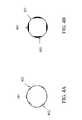
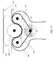
- FIG. 2illustrates a conceptual end view diagram of a configuration of an active skinned propulsion system.
- FIG. 3illustrates an exemplary diagram of a split ring.
- FIGS. 4A and 4Billustrates exemplary embodiments of wrinkle limiting or prevention rings.
- FIGS. 5 , 6 , 7 , 8 A and 8 Billustrate exemplary diagrams of angular actuation methods to achieve steering.
- FIGS. 9 , 10 , 11 A, 11 B, 12 , and 13illustrate exemplary diagrams of skin engaging units.
- FIG. 14illustrates an exemplary diagram of a friction imparting ring.
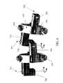
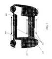
- FIGS. 15-18illustrate exemplary diagrams of a snake-type robot.
- FIGS. 19A , 19 B, 20 A, and 20 Billustrate exemplary diagrams of tails of a snake-type robot.
- FIG. 21illustrates exemplary pattern generation software architecture for controlling a snake-type robot.
- FIGS. 22 , 23 , 24 A, 24 B, and 24 Cillustrate exemplary diagrams of a snake-type robot's movement capabilities.
- FIG. 25illustrates an exemplary diagram of friction enhancing elements attached to the torus skin.
- FIG. 26illustrates a distributed power system of an active skin propulsion system.
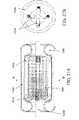
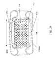
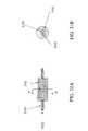
- FIGS. 27A , 27 B, 28 , and 29illustrate exemplary diagrams of drive segments.
- FIG. 30illustrates an exemplary diagram of multi-skin multi-segment snake-type robot.
- FIGS. 31A , 31 B, 32 A, 32 B, 33 A, 33 B, 34 , and 35illustrates an exemplary diagram depicting the assembly of a multi-skin multi-segment snake-type robot.
- FIG. 36illustrates an exemplary diagram of a single skin multi-segment snake-type robot.
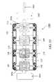
- FIGS. 1 and 2illustrate lateral and end views of an active skinned propulsion system that can be used in among other things a snake type robot 100 .
- the active skin propulsion system in FIG. 1includes a toroidal skin 101 and a drive system.
- the skin 101can be driven as an endless tread and can be described generally as having an outer run 102 and an inner run 103 . Additionally, the skin can be driven in select regions to propel the snake-type robot in other ways such as in a curved or serpentine-like manner.
- the outer run 102 of the skinforms what can be described as the body exterior 104 , and at least part of the outer run 102 engages the ground or other surface.
- the area radially inward of the inner run 103can be described as the body interior 105 .
- the drive systemincludes a plurality of drive segments 109 coupled together by links or couplings 115 between adjacent drive segments 109 . Various linking and coupling embodiments are discussed later in the specification.
- the active skin propulsion systemin several exemplary embodiments, may be considered to possess a longitudinal center line running through the inner cavity, about which the system is formed.
- the inner and outer runs of the active skin systemsurround this center line and may be considered to form cylinders, tubes and other related geometric shapes.
- the location of such theoretical center linemay be apparent, for example, in FIGS. 1 , 8 A, 8 B, 16 , 17 , and 26 , among others.
- the drive segmentis composed of a motor 110 , angularly spaced skin engaging units 11 , spacer members 112 , and belts 113 .
- the skin engaging unitsare preferably angularly spaced equally around the body. In FIG. 2 , the four skin engaging units and adjoining spacer members 112 depicted are arranged 90° apart around the body.
- the skin engaging unit 111includes a motion assisting component 106 located between the inner run 103 and the outer run 102 .
- the motion assisting component 106is a friction imparting ring 107 including two idler wheels 108 .
- the motion assisting componentin other embodiments may include lobed solid structures in lieu of idler wheels 108 .
- the frictional imparting ring 107may be composed of various metals, plastics, and other structural materials. Light weight metals such as aluminum serve the structural requirements of the ring while minimizing the weight of the robot 100 .
- a skin engaging unitfurther includes a drive wheel 114 , a friction imparting ring 107 and two idler wheels 108 attached to the friction imparting ring.
- the motor 110drives the drive wheels either directly or indirectly through the belt 113 .
- the drive wheelcan be held in place by the spacer member 112 or directly attached to the motor 110 .
- Portions of the inner run 103 of the skin 101are pinched between the friction imparting ring 107 , the idler wheels 108 , and the drive wheel 114 and are frictionally engaged and moved relative to the outer run 102 . Since the skin 101 is an endless body, the frictional movement of the inner run 103 of the skin forces the outer run 102 of the skin to move. The resulting motion of the outer run 102 of the skin when in contact with the surface or the environment propels the body rectilinearly.
- the drive systemdrives the skin 101 as a tread to propel the body and it may also drive the skin to move and turn the body in serpentine-like and other manners as will become evident from the description to follow.
- both such drive functionsare performed by common components and are effected by engaging the skin 101 to impart forces to the skin 101 .
- At least one driven wheel and a cooperating surface on the opposing side of the inner run 103pinch the skin 101 such that a rotating wheel frictionally forces the inner run 103 to move thereby propelling the snake-type robot 100 .
- the motor utilized in the drive systemmay vary depending on the desired functionality of the device.
- the motors 110are closed-loop encoded frameless DC motors built into the drive wheels themselves and allow precise vertebral or segmental control. Small skin-drive motors at each drive segment may be used to evenly spread weight, drive power task, and increase fault tolerance.
- the skin drivecan also be powered by the new generation of ultrasonic motors, which offer high torque at low RPM.
- the motor, electrical components, and a portable power source, should the device have such a feature,could be located within a central portion of the interior of the body 105 .
- the motor 110may also be located within the drive wheel 114 .
- FIG. 2also depicts the outer run of the torus skin 102 .
- the outer run 102 of the skindefines the exterior of the body, while the area radially inward of the inner run 103 of the skin is considered the interior of the body 105 .
- the torusan exemplary embodiment of which is depicted in the end view of FIG. 2 , is generally a doughnut-like shape in which the inner run 103 and outer run 102 of the skin 101 form the outer ring of the donut shape. This end shape extends in a cylindrical manner from the end doughnut appearing plane.
- the torusforms generally a flexible tube with internal segments linked together within the body interior 105 .
- FIG. 3is a schematic diagram of an exemplary embodiment of a friction imparting ring 107 placed between the inner run 103 and the outer run 102 of the skin 101 .
- the friction imparting ring 107is formed by two or more angular sections 301 and is thus a split ring.
- the split ring feature of the friction imparting ringfurther facilitates its placement between the inner run 103 and outer run 102 of the torus during assembly which is described later.
- the split ring in FIG. 3is composed of two angular sections 301 which contain internal holes 302 that are configured to hold springs 303 . These springs 303 hold the friction imparting ring 107 together structurally through tension force supplied from the springs. Any conventional tension spring may be used to supply the tensioning force that holds the friction imparting ring 107 together.
- FIG. 4Adepicts a friction imparting ring 107 constructed with bellows 402 that spreads the skin as the skin slides over the bellowed area.
- the bellowsprovide room for expansion and provides additional circumferential space for the skin to spread over the ring.
- the bellowed ringforces wrinkling to occur away from the skin engaging units 111 .
- FIG. 4Bdepicts a friction imparting ring 107 constructed with selected areas of varying thickness 403 to also allow additional circumferential spreading of the skin.
- the additional circumferential spreading room coupled with any tangential tension supplied by these friction imparting ring geometrieslimits or eliminates detrimental skin wrinkling and forces the remaining wrinkling to occur away from the skin engaging units 111 .
- FIGS. 5 , 6 , 7 , 8 A, and 8 Bare illustrative diagrams of embodiments for achieving angular actuation that can be used to steer the torus skin body.
- the actuation embodiments depicted in FIGS. 5-8 and described belowcan be used in any snake-type robot depending on the desired actuation and steering functionality.
- universal joints, solenoids, bearings or any conventional linking device or mechanism that allows movement or pivotmay be used as the connecting device 115 that connects the drive segments.
- the body's angular motioncan be a result of Shape Memory Alloys (SMA), or “muscle” actuators based on pneumatics, metal hydride, or piezo-electric contractions.
- SMAShape Memory Alloys
- the single sided arrow 602 located on the drive wheelsindicate the rotational direction of each drive wheel in order to cause the body to move and/or to cause the drive rings to vary their position.
- the arrowsindicate the direction of rotation that could cause the snake to pivot.
- the ringsbegan longitudinally parallel to each other. In the present pivoted state the relative distance between the lower portions of the rings 604 is smaller than the relative distance between the upper portion of the rings 605 .
- FIG. 6depicts a diagram of an exemplary coupling device 115 embodiment for achieving angular actuation.
- two friction imparting rings 114are connected by angular pivots.
- Horizontal actuating member 710links the drive segment 109 to a connecting actuation box member 720 .
- the box member 720is connected to the horizontal members through pin connections 703 or any other conventional pivot connection.
- the coupling between the two friction imparting rings, and more generally the two drive segments 109 in FIG. 1may be angularly rotated in two distinct planes by pivotal pin connections 703 .
- the use of two pin connections, each of which allows angular rotation in orthogonal planes when moved togetherallow each segment 109 to be moved three dimensionally.
- Dashed line 701represents a longitudinal axis and dashed line 702 represents a horizontal axis upon which either passive or active angular actuation between drive segments can be performed.
- active actuationis achieved by using motors or force imparting elements to cause rotation of the connections 703 around axis 701 and/or 702 .
- FIG. 7depicts an exemplary embodiment for angular actuation.
- linear mating slide cylinders 801 located between the friction imparting rings 107allow active or passive angular actuation between the drive segments. Active actuation is achieved by powering the horizontal slide cylinders. A portion of the small slide cylinder 803 is moved within the large slide cylinder 802 , thereby shortening the distance between the friction imparting rings 107 or drive segments 109 at that relative locale. This change in relative distance causes a turning, steering, or serpentine-like motion. Actuation and steering results by varying the position of the small slide cylinder 803 and large slide cylinder 802 . When the powered horizontal slide cylinder is contracted so as to shorten its horizontal length, the attached friction imparting ring 107 is angularly actuated causing that drive segment and the device at that locale to similarly move.
- FIGS. 8A and 8Bare diagrams of exemplary steering methods for snake-type robots.
- the couplingsare universal joints.
- FIG. 8Athe torus body is depicted prior to angular actuation or steering.
- the bodymay be at rest or may be moving in simple rectilinear motion.
- the drive wheels 114 of all of the skin engaging units 111are rotated preferably at the same speed and in the same direction.
- the drive wheelsfrictionally engage and drive the inner run 103 relative to the outer run 102 .
- the spacing 901 between the skin engaging units 107is uniform around the body.
- FIG. 8Bsteering, turning or serpentine-like or related motion is in progress.
- the drive wheels 114are rotating in different directions and/or at different speeds.
- the variation in direction and/or speed of drive wheel rotationcauses the relative location of the skin engaging unit to vary.
- the change in spacing 901 in FIG. 8B relative to the original spacing from the original linear or rest position depicted in FIG. 8Acauses the
- FIGS. 9-13are illustrative diagrams of further embodiments of skin engaging units, each of which may be used to drive any of the various snake-type robot embodiments later described.
- the skin engaging units 111are biased to cause forces to act on drive wheels 114 and further cause them to frictionally engage the torus skin 101 pinched between the drive wheel 114 and an opposing surface.
- the skin engaging unituses a toothed drive gear 1014 in lieu of a drive wheel 114 , to frictionally drive the skin 101 as is depicted in FIG. 9 .
- FIG. 9depicts use of toothed idler wheels 1008 located within the torus in lieu of idler wheels 108 .
- FIG. 10is a further illustrative diagram of an exemplary skin engaging unit 111 .
- three idler wheels/bearings 1108are inserted into the friction imparting ring 107 and two drive wheels 114 frictionally engage the skin 101 .
- Each drive wheel 1114pinches the skin along the surfaces of two idler wheels/bearings 1108 .
- Drive wheels 1114frictionally engage the inner run 103 of the skin when it is pinched between the drive wheels 1114 , the friction imparting ring 107 , and the idler wheels 108 .
- FIGS. 11A and 11Bare further illustrative diagrams of a skin engaging unit and a motor 110 .
- a motor 110forces two drive wheels 114 to rotate and thereby causes the inner run 103 of the torus skin to move relative to the outer run 102 . More specifically, portions of the inner run are pinched between the drive wheels 114 and the motion assisting component 106 which is often comprised of a friction imparting ring located within the torus.
- the motion assisting component 1206is a solid structure.
- FIGS. 11A and 11Billustrate a single motor driving a plurality of drive wheels; however, two different drive biases are illustrated. In FIG. 11A the motor 110 drives the device through an axial belt 1201 .
- An axial beltengages the axis region of each drive wheel and causes rotation.
- the motor 110drives the device through an outer surface belt 1202 engaging the outer surface of both of the drive wheels 114 . Additionally, a portion of the outer surface belt is pinched between the drive wheels 114 , the inner run 103 of the skin 101 , and the motion assisting component 1206 and the belt friction engages the skin and forces the inner run 103 of the skin to move relative to the outer run 102 of the skin 101 .
- FIGS. 12 and 13are further embodiments of the drive geometry depicted in FIG. 11B .
- a compliant drive system housing 1301that functions similarly to a spacer member 112 is illustratively depicted.
- the compliant drive systemallows movement longitudinally between the inner run 103 and the interior body 105 or motor 110 .
- the compliant drive system housing 1301absorbs bumps or surface changes and allows continual frictional engagement of the skin by the skin engaging unit 111 .
- a double-sided toothed drive belt 1302connects the motor 110 to the drive wheels 114 .
- the double-sided toothed drive belt 1302meshes with teeth molded into an idler wheel 1008 pinching the skin 101 between.
- the motor 110rotates the belt 1302 and the drive wheel 114 , the skin 101 is moved and propulsion occurs.
- the torusmay be toothed as well to allow it to directly mesh with the toothed belt as is illustrated in FIG. 13 .
- FIG. 14is a diagram of an exemplary embodiment of a drive segment 109 .
- This drive segmentis comprised of a friction imparting ring 107 , drive wheels 114 with interior electric motors and gear reducers, a servo and drive electronics circuit board 503 that is attached to the friction imparting ring, and solenoids or linear actuators 504 .
- the solenoids or linear actuatorsprovide angular actuation and are connected to the next vertebra.
- a power and control cable 505is located within the radial interior of the circuit board, and more generally, the radial interior of the friction imparting ring.
- a separate motor located within each drive wheelallows precise control of each drive wheel. Additionally, each drive wheel can be moved at different angular or tangential speeds or directions. Precise control enables precise steering and pivotal motion. Certain segments of the body can be moving in a first manner or direction while other segments of the body are pivoting or moving in a completely different direction or manner. These motion capabilities enable the device to achieve complex rectilinear and non-rectilinear motion equivalent to and sometimes superior to biological snake movement. Further, by placing the motors within the drive wheels, the interior of the body can be filled with more electronics, circuitry, and cables for transferring power or transmitting signals including controls, video recordings, or sensor readings.
- FIGS. 15-18depict exemplary embodiments of snake-type robots.
- One snake-type robothas a head 1801 and a tail 1802 , but the snake-type robot need not have either.
- the snake robotis considered to have a body 1800 , a head 1801 , and/or tail 1802 .
- the head and tail membersare attached to the body.
- a cable or cord 1803may be attached to the tail 1802 of the snake-type robot through which power may be supplied to the robot and signals, data, and controls may be transferred to and from the snake through the cable or cord.
- the head 1801may also include further function enhancing features that may be extended or protruded including any common mechanically operated claw for grasping, carrying, or holding objects, any common suction device for extracting small particles, or any lighting structure.
- the function enhancing featuresmay allow retrieval of objects, particles or fluids for further investigation and/or movement of the objects, particles, or fluids to a different location than the extraction locale.
- the body 1800is typically composed of a plurality of drive segments coupled together.
- the exterior of the body 1800as described earlier is defined by the outer run 102 of a torus skin. Motors, electronics, portable power sources, and various other components are housed within the interior of the body.
- the interior of the snake robotcan be defined for illustrative purposes as the area radially inward of the inner run 103 of the torus skin 101 .
- ends of the torus bodymay be covered 1804 as depicted in FIG. 15 .
- brushesmay be used that contact or are proximate to the moving skin.
- the configuration of the systemlimits the amount of foreign matter likely to enter the interior of the body.
- the moving skinenters the rear (or tail portion) of the body and exits the front (or head portion) of the body. Since the skin exits rather than enters the front of the body with respect to its general path of motion, it is unlikely to chum or irritate the surroundings and toss particles into the interior of the body.
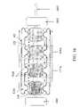
- FIG. 16is a further illustrative diagram of an exemplary embodiment of a single skin snake robot with a head 1801 , and a tail 1802 .
- the drive segments 109 A of this snake robotare composed of a skin engaging unit 111 A and a motor 110 .
- the skin engaging unit 111 Aincludes two drive wheels 1914 , and a motion assisting component 1206 that includes a friction imparting ring.
- the inner run of the torus skinis pinched between the drive wheels and the motion assisting component within the torus.
- the drive wheelsfrictionally engage the torus and cause the inner run to move relative to the outer run.
- FIG. 17is another further illustrative exemplary embodiment of a single skin snake robot with a head 1801 , and a tail 1802 .
- the motion assisting component 1506 A(the outer edge of which is illustrated by a solid line) placed within the torus skin is a tube with lobes 1501 located along the length of the tube.
- portions of the inner run of the torus skinare pinched between the drive wheels 2014 the tube, and the lobes.
- the motor 110rotates the drive wheels which frictionally engage the skin when pinched between the wheels and the lobes. As a result, the inner run of the skin is moved relative to the outer run.
- the motion assisting component or tube located within the toruscould alternatively be segmented 1506 AA (the outer edge of which is depicted as a dashed line).
- Tension springsmay be located in the spacing 2001 between the tube sections to hold the segmented tube together within the torus skin. The described segmentation may allow further angular actuation.
- the vertical dashed alignment lines 2002are for geometrical illustration purposes only and are not physical structures in the device.
- FIG. 18is another further illustrative exemplary embodiment of a single skin snake robot and is a further illustrative embodiment of the aspects depicted in FIG. 1 .
- the snake robothas a head 1801 and tail 1802 .
- the tail of this robotis capable of wireless communication thereby allowing the snake robot to traverse locations where a tethered cord could become entangled.
- the exemplary embodiments in FIGS. 15-18may possess any combination of or lack thereof a head 1801 or tail 1802 .
- the tail or headmay be multi-segmented or a single element.
- the head and tailare highly configurable attachments to the system and are used to achieve desired functionality.
- the headmay contain various perceptive sensors, video recording apparatus, sound recording apparatus, and numerous other technologies for obtaining evidence, observing or recording information, and allowing the controller of the robot to perceive the current and future environment information.
- the perceptive capabilitiesalso aid in movement of the device.
- the devicepreferably possesses among others one or more of the following sensing capabilities: vergence based-stereo, ultrasonic, bio-sensors including carbon dioxide or blood, sweat, or urine sensors, LLTV/uncooled FLIR, microphones, and/or through wall radar.
- the devicemay possess one or more of the following sensing capabilities: vergence-based stereo, ultrasonics, microphone, boroscope, LLTV/uncooled FLIR and/or through wall radar.
- the tail 1802is shaped in a generally conically or triangular shape to prevent or reduce the quantity of foreign matter to enter the torus hole and possibly impede propulsion or various other operating systems.
- the tailmay be tethered, tethered with deployable tethered guides, or numerous other designs.
- the tailmay be used in wireless communication to allow for communication in precarious, secluded, difficult to navigate or other similar environments.
- the tail segments of the snakemay be deployable for various communications, power, weight or drag reduction, demolition, reconnaissance or mobility purposes.
- the tail portionmay function in unison with the rest of the snake or as an autonomous body upon deployment.
- FIGS. 19A and 19Billustrate schematic diagrams of snake-type robot configurations with a head 1801 connected to a single torus skin multiple segmented body 2401 and a multi-segment deployable tail 2402 .
- FIG. 19Aillustrates an exemplary schematic diagram of deployment of tethered guides that can be used for among other things negotiation of difficult, narrow or precarious locations, as well as for communication purposes.
- the tether 1803as depicted in FIG. 19A , may be used for power and/or control communication.
- FIG. 19Billustrates an exemplary schematic diagram of a deployed segment of the snake for use in wireless communications. Wireless communications points 2403 allow the snake robot to continue operation in areas where traditional wireless communication may fail.
- the communication pointcan be carried with the snake until it encounters difficult terrain and the tight locale in which it will be operating.
- the cableis then deployed in close proximity to where the snake will be operating, and thus communication, transmission and control can be facilitated.
- the snake-type robotuses a portable power source to allow movement when the tether 1803 is not connected to the body.
- FIGS. 20A and 20Billustrate further aspects of a snake tail where a single power source 2303 is used to power the motors 110 of the robot snake.
- the power sourceis located in an end portion of the device in the tethered tail.
- a single power sourcefacilitates the integration of new power technologies.
- the power sourcesthat may be used are lithium-ion batteries and capacitors. Any conventional battery may be used. These sources are light, energy efficient, and may be moldable.
- the power sourcecan be molded into shapes and orientation that conform with the design of the snake robot and its particular skin propulsion system. Tight integration can be achieved and power can be distributed along the snake body.
- a cable tether 1803may provide power, video, and control communications between the device and an operator control unit.
- the tethermay be spooled 2302 in the tail section to eliminate the need to drag the tether, limiting snags and drag. If a snake transitions to untethered operation it can disconnect and deploy an antenna to communicate with the tethered end as illustrated in the lateral exemplary diagram in FIGS. 19A and 19B .
- a snake robotmay possess multiple modes of operation including both tethered and untethered operation. Such capabilities may be enabled through use of an electronic interlock or similar connection means that may be used to connect the tail to the rest of the body as illustrated in FIG. 20A and 20B . Since the tethered end may become a wireless transmission point, communications underground, in tunnels, in rubble and in dense foliage is possible. Ultra-Wide Band technology may alternatively be implemented as it is known to possess superior multi-path noise immunity.
- Any conventional remote control systemsmay be used to control the snake-type robot.
- a computer or a human with the aid of computer technologymay also control the device.
- An operator control unitwhich can comprise any conventional computer technology or PDA or similar device, can be used to display a sensor-eye view from the device's cameras, a display of the device's body configuration, and a terrain map with the selected or proposed path.
- use of visual serving technologycan be used to allow significant automatic movement. For example, the operator selects a target in a video image for the device to approach. The device then moves itself toward the target, corrects movement errors, and updates its tracking template as the device approaches the target.
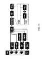
- FIG. 21is an illustrative flowchart showing how feedback from the sensors within the snake-type robots head 1801 and operator controls are combined using a pattern generator to move each select drive segment 109 (i.e. vertebra) at the appropriate time and in the appropriate manner.
- the device's interaction with an operatormay range from continuous control inputs during teleoperation to periods of complete autonomy during visual serving. In this manner, the snake-type robots can perform snake-like movements.
- the operator control unitmay include a joystick or touch screen that may be used to “drive the head” of the snake-type robot while the on-board pattern generator produces control inputs for the spine of the device. Additional controls may be utilized for manual mobility mode selection and grabber control.
- Control system hardwaremay be composed of two parts: a centralized “brain” responsible for high-level planning, sensor processing, and goal-seeking; and a “nervous system” which directly controls actuators, gathers feedback from sensors that may be located on the body, and performs reactive or reflex behaviors.
- the main processormay consist of a small, powerful single-board computer.
- the “spinal cord”may consist of a series of low-cost micro-controllers, one located in each drive segment or vertebra of the snake. All actuators within a single vertebra are under direct control of the local micro-controller.
- the controllersare interconnected with each other and the main processor via a “spinal-cord”—a bi-directional serial interface bus (CAN-bus or I 2 C bus depending on controller and main processor selection).
- the “brain”performs all high-level planning sensor processing and intelligent control.
- the pattern generatorcombines the resulting modal commands with the heading and speed commands from the arbiter to generate snake-like body motions.
- the pattern generator's control signalsare passed through the serial bus to the first micro-controller node, which performs appropriate actions and propagates the command to the next micro-controller node after a time delay based on the speed of the body motion. In this manner, control signals are propagated to all nodes along the “spinal cord.”
- sensory input and motion feedback data from each body segmentare passed to the “brain” for additional processing. Decentralization of low-level control functions enables a degree of purely reactive control similar to involuntary motion in humans, and animals. For example, the detection of an impinging object may trigger local body movement to leverage against the object for increased efficiency on unstable terrain.
- a Finite-Analytic Navier-Stokes (FANS) codemay be used to simulate the physics of the anguilliform swimming motion.
- FANSFinite-Analytic Navier-Stokes
- RANSReynolds-Averaged Navier-Stokes
- a moving-body computational model of the robot's anguilliform swimming motion and high-resolution gridcan be used.
- the modelrepresents among other things the device's shape, weight distribution, kinematics, actuator speeds and limits, and buoyancy information.
- Time-accurate RANS simulationscan be performed to provide the needed forces, powers, and flow details. Simulations can be done in calm water to show the thrust generation mechanism and swimming speed.
- the toroidal skincan act as a completely sealed bladder. This functionality can be exploited to adjust buoyancy balance. Slight positive buoyancy is achieved so that the robot can swim on or beneath the surface.
- Some biological snakesuse anguilliform motion to burrow into sand, vegetative matter, and loose soil.
- the high traction provided by full-body skin propulsion, combined with anguilliform motiondrives the snake body into snow, sand, vegetative matter, and loose soil.
- Robot snakesalso have unique climbing abilities. In some cases, robot snakes will outperform biological snakes. Some snakes such as rat snakes climb tree trunks using straight rectilinear motion. Other snakes use a combination of rectilinear and lateral undulation. Robot snakes may be able to perform these maneuvers and have the additional advantage of a full-length skin propulsion system.
- FIG. 2there is an orthogonal arrangement of the spacer members 112 that allows the drive wheels of the skin engaging units 111 to move the skin 101 .
- An orthogonal arrangement of the spacer members 112 and skin engaging units 111allows the active skin propulsion system to operate in any side up mobility. Movement of the device is not impeded should the device be inverted from its original orientation. The entire outer run surface contact element of the device serves as a propulsion means. Any side up mobility allows this device to travel in extremely rough terrain. It further allows the device to traverse steep inclines in which devices would be immobilized if inverted.
- the devicealso allows the device to travel in tight corners, pipes, tunnels, air ducts, and similar hard to reach locales in which locomotion though movement on a horizontal surface may be impossible. Even if frictional traction is only available in random orientations throughout a passageway the active skin system can traverse it.
- FIGS. 22 , 23 24 A, 24 B, and 24 CVarious exemplary movement capabilities of the device are illustrated in FIGS. 22 , 23 24 A, 24 B, and 24 C.
- FIG. 22is an illustrative depiction of a snake robot's ability to perform rectilinear motion. Rectilinear motion allows the snake to crawl pipes, negotiate uneven terrain, and move quickly.
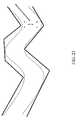
- FIG. 23the snake robot's steering capabilities combined with its rectilinear propulsion allow it to maneuver in irregular and jagged bends in small areas.
- FIG. 24Adepicts the robot snake's ability to climb poles and similar structures. Using its vertical and lateral actuators, the snake wraps its body around the pole and grips it.
- FIG. 24Billustrates an exemplary method for a robot snake to climb an air duct and other interior surfaces larger than the body's diameter.
- the lateral actuatorsexert pressure against the sides of the duct.
- the skin drivepowers the skin, causing the snake to ascend the duct.
- FIG. 24Cillustrates an exemplary method for a robot snake to enter a small opening in a barricade. Using the vertical actuators to lift the head to the appropriate height, the snake moves toward the opening using rectilinear motion. When the skin contacts the edge of the opening, traction is gained, and the snake can proceed through the opening by passing the vertical “step” down the body.
- GVGGeneralized Voronoi Graphs
- strain or pressure gaugescan also be used to enable the vertebrae controllers to sense the local skin conditions. By manipulating local skin drive motors and signaling neighboring vertebra, local areas of high strain or slackness can be moderated. During motion over complex terrain that may induce drag, variable friction, twisting strains on the skin, local feedback loops may be used to reduce differential stress, thus improving efficiency and skin life.
- a torus skin that defines the body of a snake-type robotcan be fit to any convex shape and allows robot snakes to exist in numerous shapes.
- robot-type snakesmay have a roughly triangular or a flattened elliptical cross-section similar to the shapes of certain biological snakes.
- the aforementioned cross-sectional designsmay increase the contact area on hard flat surfaces; however, the active skin can be fit to any convex shape to achieve desired functionality.
- the torus skinwhich defines the body provides many functions in addition to its use for propulsion. Among the characteristics that affect skin performance and functionality include texture, flexibility, and chemical resistance.
- the material composition of the skinis varied according to desired functionality. The skin should possess a certain amount of flexibility yet still be strong enough to withstand continuous cycling around the body of robotic drive components.
- Elastomersare a likely choice for the torus skin of a snake-type robot.
- Monolithic materials, woven and composite materials and flexible Kevlar-impregnated compositesare among the numerous types of materials that can be used to compose the active skin.
- Butyl rubber sheeting, chloroprene (neoprene), and translucent rubber sheetingare materials that can be used to compose the torus skin 101 . Based on desired functionality, various skin materials may be chosen.
- differential elasticitymay be desired to shrink radially into the center hole while maintaining a fixed skin length. Some axial elasticity may be needed to handle steering baseline changes.
- Each polymer chosenmay have tradeoffs for elongation, hardness, abrasion and resistance.
- chemical resistance to conventional lubricantsmay be a desirable property when choosing skin 101 composition to allow lubricants to be used to reduce the friction inside the skin.
- a preferred skin embodimentmay be waterproof or water resistant but the skin does not have be resistant to water.
- FIG. 25is an illustrative diagram of further aspects of skin engaging units in use with an active skin with friction enhancing elements 2501 .
- the friction enhancing elementsprotrude from the skin and can be affixed as part of the skin, as an attached layer covering part or all of the skin, or preferably as elements molded to or bonded within the skin material. Other changes may be made to the outer surface of the skin to allow better grip and contact between the skin and the environment that it contacts while imparting motion on the body.
- Friction enhancing elementsthat fold or compress when contacting the drive wheel or wheels allowing easier passage when pinched as the skin moves during propulsion may also be used.
- the inner run of the torus skin with friction enhancing elements 2501is pinched between a friction imparting ring 107 and attached idler wheels 108 located within the torus skin and a drive wheel 114 pinch the skin with scales.
- assembly of the devicemay be performed in numerous ways.
- assembly split ringssuch as the ring depicted in FIG. 3 are installed in the active skin propulsion device by first placing the split drive rings inside the skin between inner and outer runs of the skin. The skin is then sealed. The torus, with friction imparting rings, is then pulled over the internal body and the internal body portions of the drive segments. More specifically, the split friction imparting rings are spread to move over the drive wheels on the drive segment. When the correct ring associated with the drive segment is in position, the ring is spread and moved over the drive wheels to trap them in the center dip. In essence the ring is snapped into place.
- a head and/or a tailmay be attached to the body.
- the springs within the split friction imparting ringprovide enough tension to capture the drive wheels and successfully allow the drive wheels to frictionally engage the skin.
- Various methods of assemblyin addition to the method described here can be used to construct or assemble the device depending on the specific components used, the specific structures included, the size of the device as a whole or certain portions of the device, and the materials used in the device.
- the snake-type robotcan be powered through a tether attached to a power source and/or a portable power source.
- An exemplary diagram of one embodiment of a snake-type robot containing portable power sources 3001is depicted in FIG. 26 .
- the power sources (batteries) depictedare located in close proximity to the motors 110 within each vertebra or drive segment. Commonly used batteries may be utilized and specifically chosen based on desired functionality including weight, duration, and power characterisitcs. By locating the portable power sources throughout the device, the weight associated with each of the sources can also be distributed throughout the device.
- the power sourcesmay also be formed to fit a specific shape including the overall shape of the robot.
- Active skin snake-type robotscan be single skinned devices (as shown in FIGS. 15-18 ) or multiple skinned devices (as shown in FIG. 30 ).
- the coupling 115 used to connect drive segments of the snake robot togethervary depending on the desired functionality, required drive and steering geometry and characteristics, and required rigidity of the connection. These couplings were described earlier in the description.
- FIGS. 27A , 27 B, 28 , and 29are illustrative diagrams of further embodiments of drive segments of an active skinned propulsion system.
- the drive segmentincludes a motor 110 , drive wheels 1514 and a tube 1506 located within the torus skin as a motion assisting component.
- the tube in this embodimentcontains lobed ends 1501 further allowing the drive wheels to frictionally engage the skin.
- the drive wheels 1514 in this embodimentare located diagonally from the center of the drive segment around the circumference of the body as is depicted in the end view shown in FIG. 27B .
- arrowsfurther illustrate the direction of movement of the skin and drive wheels of the drive segment embodiment shown in FIGS. 27A and 27B in order to propel the body.
- the drive segment embodiments depicted in FIGS. 27A , 27 B, and 28can alternatively be made with spring loaded half-segments.
- the drive segmentcontains motion assisting tubes 1506 A split in half at their longitudinal mid-point 1701 . Between the half segments, springs are placed that hold the tube together. When sufficient actuation force occurs, the spring allows actuation.
- the geometry of the half segment, especially their shorter length and spring connection,allow greater angular actuation and more responsive or sharper turning capabilities.
- FIG. 30several drive segments similar to those described in FIG. 29 are linked together to form a snake-type robot composed of multiple skins. Each drive segment includes its own torus skin body.
- the exemplary snake-type robot depicted in FIG. 30is multi-skinned and multi-segmented.
- FIGS. 31A , 31 B, 32 A, 32 B, 33 A, 33 B, 34 , 35 , and 36illustrate two further embodiments of a snake-type robot at different completion points in the assembly process.
- These particular snake-type robot embodimentscan be constructed so as to be very small in physical size. Specifically, just to further illustrate the approximate size of the miniature embodiments, these snake-type robots can measure less than one quarter of an inch or smaller in diameter, thereby allowing maneuverability in the tightest of quarters.
- FIGS. 31A and 31Bare illustrative diagrams of the motor and accompanying shafts used in a segment of an embodiment of a snake-type robot.
- FIG. 31 Adepicts a diagram of a dual shaft motor 3101 that powers dual shafts 3102 . Attached to each of the dual shafts is a drive worm gear 3103 . The threading of the worm gears that will assist in driving the snake-type robot may be varied depending on end goal functionality with respect to the desired speed and power output.
- FIG. 31Billustrates an end view diagram of the dual shaft motor 3101 , the dual shafts driven by the motors 3102 , and the attached drive worm gears 3103 .
- Mating worm gears 3202are placed so as to engage the drive worm gears 3103 as depicted in FIGS. 32A and 32B . Additionally, a support structure 3201 provides rigidity and holds these gears generally in position. Further attached to the mating worm gears 3203 are friction tires 3203 that engage the torus skin of the snake-type robot and cause propulsion. Not depicted in FIGS. 32A and 32B is a further support structure that connects the quad mating worm gears 3202 and friction tires 3203 to the motor 3101 so as to prevent significant lateral movement. FIG. 32B is an end view further illustrating the arrangement depicted in FIG. 32A .
- Drive rings 3301are then placed so as to circumscribe the friction tires and attached components as is illustrated by the diagrams in FIGS. 33A and 33B .
- idler wheels 3302are utilized to engage the torus skin, however, many functionally similar structures can be utilized to aid frictional engagement.
- the torus skin 101is then installed as illustrated in FIG. 34 .
- the skinmay be pulled over the drive hardware so as to enable frictional engagement of the skin by the drive hardware.
- the drive ring 3301 utilizedmay be a split ring, such as the one illustrated in FIG. 3 , to further facilitate assembly of the device.
- a protective covering 1804may be placed over the front and/or rear ends of the drive segment to prevent foreign matter from disrupting motion as was previously shown and described with respect to FIG. 15 .
- Drive segments assembled through the steps depicted in FIGS. 31A , 31 B, 32 A, 32 B, 33 A, 33 B, and 34can be linked to form multi-skin multi-segment snake-type robots of varying length and segment numbers as is illustrated in the exemplary diagram FIG. 35 .
- angular actuators 3501are used to link the segments together and allow steering.
- batteries or other payload (represented with B or P) 3502 depending on the functionality of the particular snake-type robotmay be placed between the segments of the robot.
- structural members 3503are used to physically connect the actuators and batteries or payload to the segment itself. Attachment for structural members 3503 will usually occur at some point on the support members 3202 , as this linking would not impede any moving components and may further provide the most structurally sound attachment point.
- FIGS. 31A , 31 B, 32 A, 32 B, 33 A, and 34to construct a multi-segment multi-skin snake-type robot such as the one in FIG. 35 also can be used to construct a multi-segment single skin snake-type robot as depicted in FIG. 36 .
- the snake-type robots depicted in FIGS. 35 and 36can be utilized to achieve among other things several desirable functionalities.
- the physical structure and geometryallow for the entire snake to achieve miniature or micro proportions.
- the dual shaft motor, and worm gearsallows for one motor to drive each segment of the snake-type robot.
- the interaction and gear/thread geometry between the drive worm gears 3103 and the mating worm gears 3202allows the drive worms gears to be rotated rather quickly compared to the movement of the torus skin and gears and tires that engage the skin. This relationship further allows movement in miniature embodiments and allows snake-type robots to be utilized in even further confining environments.
Landscapes
- Engineering & Computer Science (AREA)
- Mechanical Engineering (AREA)
- Chemical & Material Sciences (AREA)
- Combustion & Propulsion (AREA)
- Transportation (AREA)
- Robotics (AREA)
- Manipulator (AREA)
Abstract
Description
Claims (20)
Priority Applications (1)
| Application Number | Priority Date | Filing Date | Title |
|---|---|---|---|
| US11/327,390US7387179B2 (en) | 2003-06-17 | 2006-01-09 | Toroidal propulsion and steering system |
Applications Claiming Priority (2)
| Application Number | Priority Date | Filing Date | Title |
|---|---|---|---|
| US10/462,789US7044245B2 (en) | 2003-06-17 | 2003-06-17 | Toroidal propulsion and steering system |
| US11/327,390US7387179B2 (en) | 2003-06-17 | 2006-01-09 | Toroidal propulsion and steering system |
Related Parent Applications (2)
| Application Number | Title | Priority Date | Filing Date |
|---|---|---|---|
| US10/462,789ContinuationUS7044245B2 (en) | 2003-06-17 | 2003-06-17 | Toroidal propulsion and steering system |
| US10/462,789DivisionUS7044245B2 (en) | 2003-06-17 | 2003-06-17 | Toroidal propulsion and steering system |
Publications (2)
| Publication Number | Publication Date |
|---|---|
| US20060261771A1 US20060261771A1 (en) | 2006-11-23 |
| US7387179B2true US7387179B2 (en) | 2008-06-17 |
Family
ID=36124410
Family Applications (3)
| Application Number | Title | Priority Date | Filing Date |
|---|---|---|---|
| US10/462,789Expired - LifetimeUS7044245B2 (en) | 2003-06-17 | 2003-06-17 | Toroidal propulsion and steering system |
| US11/327,390Expired - Fee RelatedUS7387179B2 (en) | 2003-06-17 | 2006-01-09 | Toroidal propulsion and steering system |
| US11/327,391Expired - LifetimeUS7235046B2 (en) | 2003-06-17 | 2006-01-09 | Toroidal propulsion and steering system |
Family Applications Before (1)
| Application Number | Title | Priority Date | Filing Date |
|---|---|---|---|
| US10/462,789Expired - LifetimeUS7044245B2 (en) | 2003-06-17 | 2003-06-17 | Toroidal propulsion and steering system |
Family Applications After (1)
| Application Number | Title | Priority Date | Filing Date |
|---|---|---|---|
| US11/327,391Expired - LifetimeUS7235046B2 (en) | 2003-06-17 | 2006-01-09 | Toroidal propulsion and steering system |
Country Status (1)
| Country | Link |
|---|---|
| US (3) | US7044245B2 (en) |
Cited By (42)
| Publication number | Priority date | Publication date | Assignee | Title |
|---|---|---|---|---|
| US20080164079A1 (en)* | 2006-11-13 | 2008-07-10 | Jacobsen Stephen C | Serpentine robotic crawler |
| US20080217993A1 (en)* | 2006-11-13 | 2008-09-11 | Jacobsen Stephen C | Conformable track assembly for a robotic crawler |
| US20080281231A1 (en)* | 2007-05-07 | 2008-11-13 | Jacobsen Stephen C | Method for manufacturing a complex structure |
| US20090137186A1 (en)* | 2006-05-04 | 2009-05-28 | Mattel, Inc. | Motorized toy creature |
| US20090227838A1 (en)* | 2008-03-10 | 2009-09-10 | Softscope Medical Technologies, Inc. | Propellable apparatus with passive size changing ability |
| US20090233747A1 (en)* | 2008-03-11 | 2009-09-17 | Softscope Medical Technologies, Inc. | Torque-adjusting drive mechanism for a propellable device |
| US20100078941A1 (en)* | 2007-05-01 | 2010-04-01 | Benjamin Pietro Filardo | Pliant or Compliant Elements for Harnessing the Forces of Moving Fluid to Transport Fluid or Generate Electricity |
| US20100201187A1 (en)* | 2006-11-13 | 2010-08-12 | Jacobsen Stephen C | Versatile Endless Track For Lightweight Mobile Robots |
| USD624974S1 (en)* | 2009-01-30 | 2010-10-05 | China Industries Limited | Toy snake |
| US20100287787A1 (en)* | 2009-05-12 | 2010-11-18 | Shelton/Hay Llc | Device and method for breaking caked grain in a storage bin |
| US20110065988A1 (en)* | 2009-09-17 | 2011-03-17 | Softscope Medical Technologies, Inc. | Propellable apparatus with active size changing ability |
| KR101054222B1 (en)* | 2008-10-24 | 2011-08-08 | (주)미래컴퍼니 | Series-connected motor assembly |
| US20110287690A1 (en)* | 2009-01-30 | 2011-11-24 | China Industries Limited | Toy snake |
| US20110295427A1 (en)* | 2010-05-26 | 2011-12-01 | Motzer William P | Methods and systems for inspection sensor placement |
| US8185241B2 (en) | 2006-11-13 | 2012-05-22 | Raytheon Company | Tracked robotic crawler having a moveable arm |
| US20120221016A1 (en)* | 2010-08-25 | 2012-08-30 | Fell Barry M | Path-Following Robot |
| US20120271106A1 (en)* | 2011-04-25 | 2012-10-25 | Fujifilm Corporation | Self-propelled device for endoscope |
| US8317555B2 (en) | 2009-06-11 | 2012-11-27 | Raytheon Company | Amphibious robotic crawler |
| US8392036B2 (en) | 2009-01-08 | 2013-03-05 | Raytheon Company | Point and go navigation system and method |
| US8393422B1 (en) | 2012-05-25 | 2013-03-12 | Raytheon Company | Serpentine robotic crawler |
| US8571711B2 (en) | 2007-07-10 | 2013-10-29 | Raytheon Company | Modular robotic crawler |
| US8610304B2 (en) | 2007-05-01 | 2013-12-17 | Pliant Energy Systems Llc | Mechanisms for creating undulating motion, such as for propulsion, and for harnessing the energy of moving fluid |
| USD697564S1 (en)* | 2012-10-12 | 2014-01-14 | Richard Alan Terry | Dragon toy |
| USD697563S1 (en)* | 2012-10-12 | 2014-01-14 | Richard Alan Terry | Dragon toy |
| USD697984S1 (en)* | 2012-10-12 | 2014-01-21 | Richard Alan Terry | Dragon toy |
| USD697985S1 (en)* | 2012-10-12 | 2014-01-21 | Richard Alan Terry | Dragon toy |
| US20140094088A1 (en)* | 2012-10-01 | 2014-04-03 | Innovation First, Inc. | Imitating Serpentine Motion In A Mechanical Figure |
| US8851211B2 (en) | 2010-09-30 | 2014-10-07 | Keith L. Schlee | Multi-unit mobile robot |
| US20140300211A1 (en)* | 2013-03-06 | 2014-10-09 | Massachusetts Institute Of Technology | Discrete Motion System |
| US20140336455A1 (en)* | 2013-05-10 | 2014-11-13 | J. Mathieu Massicotte | Toroidal balloon-driven vehicle |
| US8935014B2 (en) | 2009-06-11 | 2015-01-13 | Sarcos, Lc | Method and system for deploying a surveillance network |
| US9031698B2 (en) | 2012-10-31 | 2015-05-12 | Sarcos Lc | Serpentine robotic crawler |
| US9168786B2 (en) | 2011-12-02 | 2015-10-27 | Helical Robotics, Llc | Mobile robot |
| US9409292B2 (en) | 2013-09-13 | 2016-08-09 | Sarcos Lc | Serpentine robotic crawler for performing dexterous operations |
| US9566711B2 (en) | 2014-03-04 | 2017-02-14 | Sarcos Lc | Coordinated robotic control |
| US10190570B1 (en) | 2016-06-30 | 2019-01-29 | Pliant Energy Systems Llc | Traveling wave propeller, pump and generator apparatuses, methods and systems |
| US10519926B2 (en) | 2016-06-30 | 2019-12-31 | Pliant Energy Systems Llc | Traveling wave propeller, pump and generator apparatuses, methods and systems |
| US10611022B2 (en)* | 2016-11-29 | 2020-04-07 | Rolls-Royce Plc | Methods, apparatus, computer programs and non-transitory computer readable storage mediums for controlling a hyper redundant manipulator |
| US10786903B2 (en)* | 2017-10-05 | 2020-09-29 | Institute Of Nuclear Energy Research, Atomic Energy Council, Executive Yuan | Map creation system and method thereof for movable robot |
| US11209022B2 (en)* | 2016-06-30 | 2021-12-28 | Pliant Energy Systems Llc | Vehicle with traveling wave thrust module apparatuses, methods and systems |
| US11795900B2 (en) | 2016-06-30 | 2023-10-24 | Pliant Energy Systems Llc | Vehicle with traveling wave thrust module apparatuses, methods and systems |
| US12311550B2 (en) | 2020-12-31 | 2025-05-27 | Sarcos Corp. | Smart control system for a robotic device |
Families Citing this family (68)
| Publication number | Priority date | Publication date | Assignee | Title |
|---|---|---|---|---|
| US7736300B2 (en)* | 2003-04-14 | 2010-06-15 | Softscope Medical Technologies, Inc. | Self-propellable apparatus and method |
| US7216831B2 (en)* | 2004-11-12 | 2007-05-15 | The Boeing Company | Shape changing structure |
| US20060156851A1 (en)* | 2004-12-02 | 2006-07-20 | Jacobsen Stephen C | Mechanical serpentine device |
| US7708687B2 (en)* | 2005-05-27 | 2010-05-04 | Bern M Jonathan | Endoscope propulsion system and method |
| US7617891B2 (en)* | 2005-10-11 | 2009-11-17 | Schlumberger Technology Corporation | Mechanical crawler |
| US7798992B2 (en)* | 2005-11-04 | 2010-09-21 | Ethicon Endo-Surgery, Inc. | Lumen traversing device |
| JP4521363B2 (en)* | 2006-02-17 | 2010-08-11 | 昌純 高田 | Self-propelled colonoscopy |
| CN100410128C (en)* | 2006-09-28 | 2008-08-13 | 哈尔滨工业大学 | A crawler-type multi-joint articulated robot suitable for search and detection in coal mines |
| US20080215185A1 (en)* | 2006-11-13 | 2008-09-04 | Jacobsen Stephen C | Unmanned ground robotic vehicle having an alternatively extendible and retractable sensing appendage |
| GB0624242D0 (en)* | 2006-12-05 | 2007-01-10 | Oliver Crispin Robotics Ltd | Improvements in and relating to robotic arms |
| US20100113874A1 (en)* | 2007-04-04 | 2010-05-06 | Marco Quirini | Teleoperated endoscopic capsule |
| WO2008150630A2 (en)* | 2007-05-08 | 2008-12-11 | Raytheon Sarcos, Llc | Variable primitive mapping for a robotic crawler |
| WO2009010820A1 (en)* | 2007-05-09 | 2009-01-22 | Glynn Beverly Burke | Method and device for extending and retracting reach |
| CN101778756B (en)* | 2007-07-10 | 2013-01-23 | 雷神萨科斯公司 | Snake-like robotic crawler with continuous tracks |
| US20090043160A1 (en)* | 2007-08-10 | 2009-02-12 | Masazumi Takada | Self-propelled colonoscope |
| US20090105939A1 (en)* | 2007-10-22 | 2009-04-23 | Toyota Motor Engineering & Manufacturing North America, Inc. | Vehicle navigation system with obstacle avoidance |
| US8291781B2 (en) | 2007-12-21 | 2012-10-23 | Schlumberger Technology Corporation | System and methods for actuating reversibly expandable structures |
| US8733453B2 (en)* | 2007-12-21 | 2014-05-27 | Schlumberger Technology Corporation | Expandable structure for deployment in a well |
| US7896088B2 (en) | 2007-12-21 | 2011-03-01 | Schlumberger Technology Corporation | Wellsite systems utilizing deployable structure |
| WO2009129341A1 (en)* | 2008-04-15 | 2009-10-22 | Mattel, Inc. | Touch screen remote control device for use with a toy |
| KR101057469B1 (en)* | 2008-12-26 | 2011-08-17 | 한국과학기술원 | Rough terrain robot |
| WO2010126669A2 (en)* | 2009-03-25 | 2010-11-04 | Massachusetts Institute Of Technology | Cellular automotion digital material |
| US9199746B2 (en) | 2009-05-19 | 2015-12-01 | University Of Florida Research Foundation, Inc. | Attitude control system for small satellites |
| GB0910951D0 (en)* | 2009-06-24 | 2009-08-05 | Imp Innovations Ltd | Joint arrangement |
| IT1397408B1 (en)* | 2009-12-02 | 2013-01-10 | Uni Campus Bio Medico Di Roma | LOCOMOTION DEVICE AND METHOD, PARTICULARLY SUITABLE FOR ENDOSCOPIC APPLICATIONS. |
| JP2012029865A (en)* | 2010-07-30 | 2012-02-16 | Fujifilm Corp | Endoscope mounting fixture |
| DE102010034378A1 (en)* | 2010-08-13 | 2012-02-16 | Karl Storz Gmbh & Co. Kg | Shank element for an endoscope |
| JP5236035B2 (en)* | 2011-03-15 | 2013-07-17 | 富士フイルム株式会社 | Endoscope insertion aid |
| KR101255674B1 (en)* | 2011-11-02 | 2013-04-17 | 연세대학교 산학협력단 | In pipe driving robot |
| US9211134B2 (en) | 2012-04-09 | 2015-12-15 | Carefusion 2200, Inc. | Wrist assembly for articulating laparoscopic surgical instruments |
| CN102699915B (en)* | 2012-05-29 | 2014-10-08 | 淮海工学院 | Multi-sectional robot |
| US9131833B2 (en) | 2012-05-30 | 2015-09-15 | Universita Campus Bio-Medico Di Roma | Locomotion device for endoscopic applications and related methods |
| US9193402B2 (en) | 2013-11-26 | 2015-11-24 | Elwha Llc | Structural assessment, maintenance, and repair apparatuses and methods |
| US9193068B2 (en)* | 2013-11-26 | 2015-11-24 | Elwha Llc | Structural assessment, maintenance, and repair apparatuses and methods |
| WO2016076875A1 (en)* | 2014-11-13 | 2016-05-19 | Halliburton Energy Services, Inc. | Well monitoring with autonomous robotic diver |
| CN104669256B (en)* | 2015-01-06 | 2016-06-08 | 泰华宏业(天津)机器人技术研究院有限责任公司 | The flat road surface traveling attitude control method of snake-shaped robot |
| CN104691649A (en)* | 2015-01-06 | 2015-06-10 | 泰华宏业(天津)机器人技术研究院有限责任公司 | Attitude control method for snake-like robot on rough pavement |
| GB201501479D0 (en)* | 2015-01-29 | 2015-03-18 | Norwegian Univ Sci & Tech Ntnu | Underwater manipulator arm robot |
| US10675755B2 (en)* | 2015-04-27 | 2020-06-09 | Fondazione Istituto Italiano Di Tecnologia | Shape-keeping deployable structure including a pair of robotic systems of the continuum type |
| US10071303B2 (en) | 2015-08-26 | 2018-09-11 | Malibu Innovations, LLC | Mobilized cooler device with fork hanger assembly |
| CN105479453B (en)* | 2015-12-16 | 2017-09-08 | 嘉兴布鲁艾诺机器人有限公司 | A kind of New Type of Robot Arm |
| US10807659B2 (en) | 2016-05-27 | 2020-10-20 | Joseph L. Pikulski | Motorized platforms |
| GB2560354A (en)* | 2017-03-09 | 2018-09-12 | Rolls Royce Plc | Continuum robots |
| CA3075860A1 (en)* | 2017-09-13 | 2019-03-21 | Entegra LLP | Speed control devices for a smart pipeline inspection gauge |
| CN109511645A (en)* | 2017-09-20 | 2019-03-26 | 贵港市瑞成科技有限公司 | A kind of direction judges that anti-snake escapes system |
| GB201815267D0 (en)* | 2018-09-19 | 2018-10-31 | Ucl Business Plc | Capsule endoscopy |
| US11707819B2 (en) | 2018-10-15 | 2023-07-25 | General Electric Company | Selectively flexible extension tool |
| US12194620B2 (en) | 2018-10-15 | 2025-01-14 | Oliver Crisipin Robotics Limited | Selectively flexible extension tool |
| CN109566084A (en)* | 2018-12-14 | 2019-04-05 | 海南大学 | A kind of automatic betel nut cropper |
| US11702955B2 (en) | 2019-01-14 | 2023-07-18 | General Electric Company | Component repair system and method |
| US12016531B2 (en)* | 2019-05-07 | 2024-06-25 | The Regents Of The University Of Colorado, A Body Corporate | Robotic capsule endoscope |
| JP7190744B2 (en)* | 2019-05-17 | 2022-12-16 | 国立大学法人東北大学 | Surface circulation device |
| US12405187B2 (en) | 2019-10-04 | 2025-09-02 | General Electric Company | Insertion apparatus for use with rotary machines |
| US11752622B2 (en) | 2020-01-23 | 2023-09-12 | General Electric Company | Extension tool having a plurality of links |
| US11692650B2 (en) | 2020-01-23 | 2023-07-04 | General Electric Company | Selectively flexible extension tool |
| US11613003B2 (en) | 2020-01-24 | 2023-03-28 | General Electric Company | Line assembly for an extension tool having a plurality of links |
| US11371437B2 (en) | 2020-03-10 | 2022-06-28 | Oliver Crispin Robotics Limited | Insertion tool |
| US12091981B2 (en) | 2020-06-11 | 2024-09-17 | General Electric Company | Insertion tool and method |
| US12416800B2 (en) | 2021-01-08 | 2025-09-16 | General Electric Company | Insertion tool |
| CN112975926B (en)* | 2021-03-19 | 2023-07-21 | 韶关市融德创新有限公司 | Serpentine robot |
| US11654547B2 (en) | 2021-03-31 | 2023-05-23 | General Electric Company | Extension tool |
| CN113246109A (en)* | 2021-06-07 | 2021-08-13 | 哈尔滨理工大学 | Gas transmission snake-shaped robot |
| CN113942004B (en)* | 2021-09-30 | 2022-12-20 | 北京科技大学 | Snake-like soft robot based on tension structure |
| US20230191861A1 (en)* | 2021-12-20 | 2023-06-22 | Board Of Trustees Of Michigan State University | Amphibious snake robot |
| CN114738600B (en)* | 2022-03-15 | 2023-11-03 | 香港理工大学深圳研究院 | A modular pipeline defect detection software robot |
| KR102750078B1 (en)* | 2022-08-24 | 2025-01-02 | 한국로봇융합연구원 | Outer cover for robot and safety robot including same |
| WO2024191884A1 (en)* | 2023-03-10 | 2024-09-19 | University Of Notre Dame Du Lac | Self-propelled robot |
| CN118456398B (en)* | 2024-05-22 | 2024-10-22 | 上海合时智能科技有限公司 | Snake-shaped bionic robot applied to multi-terrain walking |
Citations (42)
| Publication number | Priority date | Publication date | Assignee | Title |
|---|---|---|---|---|
| US1049345A (en) | 1911-06-24 | 1913-01-07 | Walter S Dolman | Mechanical toy. |
| US2232615A (en) | 1940-11-02 | 1941-02-18 | Kupka Edward Frank | Toy |
| US3060972A (en) | 1957-08-22 | 1962-10-30 | Bausch & Lomb | Flexible tube structures |
| US3190286A (en) | 1961-10-31 | 1965-06-22 | Bausch & Lomb | Flexible viewing probe for endoscopic use |
| US3601212A (en) | 1969-12-15 | 1971-08-24 | Caterpillar Tractor Co | Cushioned track |
| US3623566A (en) | 1969-11-14 | 1971-11-30 | Arthur Orloff | Undulating body propulsion system |
| US3767263A (en) | 1971-10-29 | 1973-10-23 | J Gootee | Earth moving-tunneling equipment |
| US3797445A (en)* | 1971-01-18 | 1974-03-19 | Israel State | Transporter for use in water |
| US3941214A (en)* | 1974-04-29 | 1976-03-02 | Armor Elevator Company, Inc. | Control system for a transportation system |
| US4081182A (en)* | 1976-08-18 | 1978-03-28 | Brien Kevin P O | Ridable recreation device |
| US4319427A (en) | 1981-04-20 | 1982-03-16 | Way Jr Lee V | Magnet effected advancing toy |
| US4558971A (en) | 1984-03-06 | 1985-12-17 | David Constant V | Continuous pipeline fabrication method |
| US4636137A (en)* | 1980-10-24 | 1987-01-13 | Lemelson Jerome H | Tool and material manipulation apparatus and method |
| US4770105A (en) | 1985-08-07 | 1988-09-13 | Hitachi, Ltd. | Piping travelling apparatus |
| US4773528A (en) | 1986-09-10 | 1988-09-27 | Joy Technologies Inc. | Material transfer unit for ground-mounted FCT |
| US4821192A (en)* | 1986-05-16 | 1989-04-11 | Denning Mobile Robotics, Inc. | Node map system and method for vehicle |
| US4829442A (en)* | 1986-05-16 | 1989-05-09 | Denning Mobile Robotics, Inc. | Beacon navigation system and method for guiding a vehicle |
| US4834478A (en)* | 1988-06-30 | 1989-05-30 | Caterpillar Inc. | Track roller frame assembly |
| US4838373A (en)* | 1988-06-30 | 1989-06-13 | Caterpillar Inc. | Suspension structure for a tracked vehicle |
| US4981188A (en) | 1988-02-09 | 1991-01-01 | K. S. M. Innovations, Inc. | All terrain off road vehicle |
| US5297644A (en) | 1990-07-09 | 1994-03-29 | Framatome | Vehicle with tiltable propulsion units |
| US5355743A (en) | 1991-12-19 | 1994-10-18 | The University Of Texas At Austin | Robot and robot actuator module therefor |
| US5628667A (en) | 1996-02-26 | 1997-05-13 | Levi; Shimon | Sinuous toy |
| JPH09144482A (en) | 1995-11-16 | 1997-06-03 | Shimizu Corp | Tunnel excavator |
| US5662587A (en) | 1992-09-16 | 1997-09-02 | Cedars Sinai Medical Center | Robotic endoscopy |
| US5672044A (en)* | 1974-01-24 | 1997-09-30 | Lemelson; Jerome H. | Free-traveling manipulator with powered tools |
| JPH1122385A (en) | 1997-07-04 | 1999-01-26 | Okumura Corp | Tunnel excavator |
| US6178872B1 (en) | 1998-07-24 | 2001-01-30 | Forschungszentrum Karlsruhe Gmbh | Operating mechanism |
| US6267196B1 (en)* | 1996-11-07 | 2001-07-31 | California Institute Of Technology | High mobility vehicle |
| US20020091466A1 (en)* | 2000-11-17 | 2002-07-11 | Jeong-Gon Song | Mobile robot and course adjusting method thereof |
| US20020190682A1 (en) | 2001-03-07 | 2002-12-19 | Hagen Schempf | Gas main robotic inspection system |
| US6505525B2 (en)* | 2000-05-12 | 2003-01-14 | Aries Industries Incorporated | Apparatus and method for inspecting lateral sewer pipes |
| US6508188B2 (en)* | 2001-02-27 | 2003-01-21 | Jim Dong | Drag-free hull for marine vessels |
| US6512345B2 (en) | 2001-03-30 | 2003-01-28 | The Regents Of The University Of Michigan | Apparatus for obstacle traversion |
| US20030065250A1 (en) | 2001-09-17 | 2003-04-03 | Case Western Reserve University | Peristaltically Self-propelled endoscopic device |
| US6567687B2 (en)* | 1999-02-22 | 2003-05-20 | Yaron Front | Method and system for guiding a diagnostic or therapeutic instrument towards a target region inside the patient's body |
| US6774597B1 (en) | 2001-03-30 | 2004-08-10 | The Regents Of The University Of Michigan | Apparatus for obstacle traversion |
| US6802237B1 (en)* | 2003-04-28 | 2004-10-12 | The United States Of America As Represented By The Secretary Of The Navy | System and method for neutralization of mines using robotics and penetrating rods |
| US6824510B2 (en) | 2001-05-19 | 2004-11-30 | Korea Institute Of Science And Technology | Micro robot |
| US6846029B1 (en)* | 2001-08-09 | 2005-01-25 | Gary Dean Ragner | Torus-shaped mechanical gripper |
| US6971990B2 (en)* | 2003-04-14 | 2005-12-06 | Troy J. Ziegler | Propulsion mechanism for endoscopic systems |
| US20060089533A1 (en)* | 2003-04-14 | 2006-04-27 | Softscope Medical Technologies, Inc. | Self-propellable endoscopic apparatus and method |
Family Cites Families (1)
| Publication number | Priority date | Publication date | Assignee | Title |
|---|---|---|---|---|
| US7072832B1 (en)* | 1998-08-24 | 2006-07-04 | Mindspeed Technologies, Inc. | System for speech encoding having an adaptive encoding arrangement |
- 2003
- 2003-06-17USUS10/462,789patent/US7044245B2/ennot_activeExpired - Lifetime
- 2006
- 2006-01-09USUS11/327,390patent/US7387179B2/ennot_activeExpired - Fee Related
- 2006-01-09USUS11/327,391patent/US7235046B2/ennot_activeExpired - Lifetime
Patent Citations (42)
| Publication number | Priority date | Publication date | Assignee | Title |
|---|---|---|---|---|
| US1049345A (en) | 1911-06-24 | 1913-01-07 | Walter S Dolman | Mechanical toy. |
| US2232615A (en) | 1940-11-02 | 1941-02-18 | Kupka Edward Frank | Toy |
| US3060972A (en) | 1957-08-22 | 1962-10-30 | Bausch & Lomb | Flexible tube structures |
| US3190286A (en) | 1961-10-31 | 1965-06-22 | Bausch & Lomb | Flexible viewing probe for endoscopic use |
| US3623566A (en) | 1969-11-14 | 1971-11-30 | Arthur Orloff | Undulating body propulsion system |
| US3601212A (en) | 1969-12-15 | 1971-08-24 | Caterpillar Tractor Co | Cushioned track |
| US3797445A (en)* | 1971-01-18 | 1974-03-19 | Israel State | Transporter for use in water |
| US3767263A (en) | 1971-10-29 | 1973-10-23 | J Gootee | Earth moving-tunneling equipment |
| US5672044A (en)* | 1974-01-24 | 1997-09-30 | Lemelson; Jerome H. | Free-traveling manipulator with powered tools |
| US3941214A (en)* | 1974-04-29 | 1976-03-02 | Armor Elevator Company, Inc. | Control system for a transportation system |
| US4081182A (en)* | 1976-08-18 | 1978-03-28 | Brien Kevin P O | Ridable recreation device |
| US4636137A (en)* | 1980-10-24 | 1987-01-13 | Lemelson Jerome H | Tool and material manipulation apparatus and method |
| US4319427A (en) | 1981-04-20 | 1982-03-16 | Way Jr Lee V | Magnet effected advancing toy |
| US4558971A (en) | 1984-03-06 | 1985-12-17 | David Constant V | Continuous pipeline fabrication method |
| US4770105A (en) | 1985-08-07 | 1988-09-13 | Hitachi, Ltd. | Piping travelling apparatus |
| US4821192A (en)* | 1986-05-16 | 1989-04-11 | Denning Mobile Robotics, Inc. | Node map system and method for vehicle |
| US4829442A (en)* | 1986-05-16 | 1989-05-09 | Denning Mobile Robotics, Inc. | Beacon navigation system and method for guiding a vehicle |
| US4773528A (en) | 1986-09-10 | 1988-09-27 | Joy Technologies Inc. | Material transfer unit for ground-mounted FCT |
| US4981188A (en) | 1988-02-09 | 1991-01-01 | K. S. M. Innovations, Inc. | All terrain off road vehicle |
| US4834478A (en)* | 1988-06-30 | 1989-05-30 | Caterpillar Inc. | Track roller frame assembly |
| US4838373A (en)* | 1988-06-30 | 1989-06-13 | Caterpillar Inc. | Suspension structure for a tracked vehicle |
| US5297644A (en) | 1990-07-09 | 1994-03-29 | Framatome | Vehicle with tiltable propulsion units |
| US5355743A (en) | 1991-12-19 | 1994-10-18 | The University Of Texas At Austin | Robot and robot actuator module therefor |
| US5662587A (en) | 1992-09-16 | 1997-09-02 | Cedars Sinai Medical Center | Robotic endoscopy |
| JPH09144482A (en) | 1995-11-16 | 1997-06-03 | Shimizu Corp | Tunnel excavator |
| US5628667A (en) | 1996-02-26 | 1997-05-13 | Levi; Shimon | Sinuous toy |
| US6267196B1 (en)* | 1996-11-07 | 2001-07-31 | California Institute Of Technology | High mobility vehicle |
| JPH1122385A (en) | 1997-07-04 | 1999-01-26 | Okumura Corp | Tunnel excavator |
| US6178872B1 (en) | 1998-07-24 | 2001-01-30 | Forschungszentrum Karlsruhe Gmbh | Operating mechanism |
| US6567687B2 (en)* | 1999-02-22 | 2003-05-20 | Yaron Front | Method and system for guiding a diagnostic or therapeutic instrument towards a target region inside the patient's body |
| US6505525B2 (en)* | 2000-05-12 | 2003-01-14 | Aries Industries Incorporated | Apparatus and method for inspecting lateral sewer pipes |
| US20020091466A1 (en)* | 2000-11-17 | 2002-07-11 | Jeong-Gon Song | Mobile robot and course adjusting method thereof |
| US6508188B2 (en)* | 2001-02-27 | 2003-01-21 | Jim Dong | Drag-free hull for marine vessels |
| US20020190682A1 (en) | 2001-03-07 | 2002-12-19 | Hagen Schempf | Gas main robotic inspection system |
| US6512345B2 (en) | 2001-03-30 | 2003-01-28 | The Regents Of The University Of Michigan | Apparatus for obstacle traversion |
| US6774597B1 (en) | 2001-03-30 | 2004-08-10 | The Regents Of The University Of Michigan | Apparatus for obstacle traversion |
| US6824510B2 (en) | 2001-05-19 | 2004-11-30 | Korea Institute Of Science And Technology | Micro robot |
| US6846029B1 (en)* | 2001-08-09 | 2005-01-25 | Gary Dean Ragner | Torus-shaped mechanical gripper |
| US20030065250A1 (en) | 2001-09-17 | 2003-04-03 | Case Western Reserve University | Peristaltically Self-propelled endoscopic device |
| US6971990B2 (en)* | 2003-04-14 | 2005-12-06 | Troy J. Ziegler | Propulsion mechanism for endoscopic systems |
| US20060089533A1 (en)* | 2003-04-14 | 2006-04-27 | Softscope Medical Technologies, Inc. | Self-propellable endoscopic apparatus and method |
| US6802237B1 (en)* | 2003-04-28 | 2004-10-12 | The United States Of America As Represented By The Secretary Of The Navy | System and method for neutralization of mines using robotics and penetrating rods |
Non-Patent Citations (3)
| Title |
|---|
| A Robot Gets Down and Dirty, Artificial Intelligence, Popular Science, Jul. 2003, p. 42. |
| Budget Robitics, http://www.budgetrobotics.com/shop/index.php?shop=1&cat=49, Jun. 3, 2003, pp. 1-2. |
| Raving Toy Maniac, http://www.toymania.com/news/messages/2862.shtml, Jun. 3, 2003, pp. 1-3. |
Cited By (59)
| Publication number | Priority date | Publication date | Assignee | Title |
|---|---|---|---|---|
| US20090137186A1 (en)* | 2006-05-04 | 2009-05-28 | Mattel, Inc. | Motorized toy creature |
| US8376804B2 (en)* | 2006-05-04 | 2013-02-19 | Mattel, Inc. | Motorized toy creature |
| US8042630B2 (en) | 2006-11-13 | 2011-10-25 | Raytheon Company | Serpentine robotic crawler |
| US20080164079A1 (en)* | 2006-11-13 | 2008-07-10 | Jacobsen Stephen C | Serpentine robotic crawler |
| US20080217993A1 (en)* | 2006-11-13 | 2008-09-11 | Jacobsen Stephen C | Conformable track assembly for a robotic crawler |
| US20100201187A1 (en)* | 2006-11-13 | 2010-08-12 | Jacobsen Stephen C | Versatile Endless Track For Lightweight Mobile Robots |
| US8205695B2 (en) | 2006-11-13 | 2012-06-26 | Raytheon Company | Conformable track assembly for a robotic crawler |
| US8185241B2 (en) | 2006-11-13 | 2012-05-22 | Raytheon Company | Tracked robotic crawler having a moveable arm |
| US8002365B2 (en) | 2006-11-13 | 2011-08-23 | Raytheon Company | Conformable track assembly for a robotic crawler |
| US20100078941A1 (en)* | 2007-05-01 | 2010-04-01 | Benjamin Pietro Filardo | Pliant or Compliant Elements for Harnessing the Forces of Moving Fluid to Transport Fluid or Generate Electricity |
| US8610304B2 (en) | 2007-05-01 | 2013-12-17 | Pliant Energy Systems Llc | Mechanisms for creating undulating motion, such as for propulsion, and for harnessing the energy of moving fluid |
| US8432057B2 (en) | 2007-05-01 | 2013-04-30 | Pliant Energy Systems Llc | Pliant or compliant elements for harnessing the forces of moving fluid to transport fluid or generate electricity |
| US8434208B2 (en) | 2007-05-07 | 2013-05-07 | Raytheon Company | Two-dimensional layout for use in a complex structure |
| US20080281231A1 (en)* | 2007-05-07 | 2008-11-13 | Jacobsen Stephen C | Method for manufacturing a complex structure |
| US8002716B2 (en) | 2007-05-07 | 2011-08-23 | Raytheon Company | Method for manufacturing a complex structure |
| US8571711B2 (en) | 2007-07-10 | 2013-10-29 | Raytheon Company | Modular robotic crawler |
| US20090227838A1 (en)* | 2008-03-10 | 2009-09-10 | Softscope Medical Technologies, Inc. | Propellable apparatus with passive size changing ability |
| US8276480B2 (en) | 2008-03-11 | 2012-10-02 | Fujifilm Corporation | Torque-adjusting drive mechanism for a propellable device |
| US20090233747A1 (en)* | 2008-03-11 | 2009-09-17 | Softscope Medical Technologies, Inc. | Torque-adjusting drive mechanism for a propellable device |
| KR101054222B1 (en)* | 2008-10-24 | 2011-08-08 | (주)미래컴퍼니 | Series-connected motor assembly |
| US8392036B2 (en) | 2009-01-08 | 2013-03-05 | Raytheon Company | Point and go navigation system and method |
| US8641472B2 (en)* | 2009-01-30 | 2014-02-04 | China Industries Limited | Toy snake |
| US20110287690A1 (en)* | 2009-01-30 | 2011-11-24 | China Industries Limited | Toy snake |
| USD624974S1 (en)* | 2009-01-30 | 2010-10-05 | China Industries Limited | Toy snake |
| US20100287787A1 (en)* | 2009-05-12 | 2010-11-18 | Shelton/Hay Llc | Device and method for breaking caked grain in a storage bin |
| US8317555B2 (en) | 2009-06-11 | 2012-11-27 | Raytheon Company | Amphibious robotic crawler |
| US8935014B2 (en) | 2009-06-11 | 2015-01-13 | Sarcos, Lc | Method and system for deploying a surveillance network |
| US8550986B2 (en) | 2009-09-17 | 2013-10-08 | Fujifilm Corporation | Propellable apparatus with active size changing ability |
| US20110065988A1 (en)* | 2009-09-17 | 2011-03-17 | Softscope Medical Technologies, Inc. | Propellable apparatus with active size changing ability |
| CN102917844A (en)* | 2010-05-26 | 2013-02-06 | 波音公司 | Method and system for inspecting sensor placement |
| US9149929B2 (en)* | 2010-05-26 | 2015-10-06 | The Boeing Company | Methods and systems for inspection sensor placement |
| US20110295427A1 (en)* | 2010-05-26 | 2011-12-01 | Motzer William P | Methods and systems for inspection sensor placement |
| US9554860B2 (en) | 2010-08-25 | 2017-01-31 | Barry M. Fell | Path-following robot |
| US20120221016A1 (en)* | 2010-08-25 | 2012-08-30 | Fell Barry M | Path-Following Robot |
| US8974372B2 (en)* | 2010-08-25 | 2015-03-10 | Barry M. Fell | Path-following robot |
| US8851211B2 (en) | 2010-09-30 | 2014-10-07 | Keith L. Schlee | Multi-unit mobile robot |
| US20120271106A1 (en)* | 2011-04-25 | 2012-10-25 | Fujifilm Corporation | Self-propelled device for endoscope |
| US9545965B2 (en) | 2011-12-02 | 2017-01-17 | Helical Robotics, Llc | Mobile robot |
| US9168786B2 (en) | 2011-12-02 | 2015-10-27 | Helical Robotics, Llc | Mobile robot |
| US8393422B1 (en) | 2012-05-25 | 2013-03-12 | Raytheon Company | Serpentine robotic crawler |
| US9463393B2 (en)* | 2012-10-01 | 2016-10-11 | Innovation First, Inc. | Imitating serpentine motion in a mechanical figure |
| US20140094088A1 (en)* | 2012-10-01 | 2014-04-03 | Innovation First, Inc. | Imitating Serpentine Motion In A Mechanical Figure |
| USD697985S1 (en)* | 2012-10-12 | 2014-01-21 | Richard Alan Terry | Dragon toy |
| USD697563S1 (en)* | 2012-10-12 | 2014-01-14 | Richard Alan Terry | Dragon toy |
| USD697564S1 (en)* | 2012-10-12 | 2014-01-14 | Richard Alan Terry | Dragon toy |
| USD697984S1 (en)* | 2012-10-12 | 2014-01-21 | Richard Alan Terry | Dragon toy |
| US9031698B2 (en) | 2012-10-31 | 2015-05-12 | Sarcos Lc | Serpentine robotic crawler |
| US20140300211A1 (en)* | 2013-03-06 | 2014-10-09 | Massachusetts Institute Of Technology | Discrete Motion System |
| US9693676B2 (en)* | 2013-05-10 | 2017-07-04 | J. Mathieu Massicotte | Toroidal balloon-driven vehicle |
| US20140336455A1 (en)* | 2013-05-10 | 2014-11-13 | J. Mathieu Massicotte | Toroidal balloon-driven vehicle |
| US9409292B2 (en) | 2013-09-13 | 2016-08-09 | Sarcos Lc | Serpentine robotic crawler for performing dexterous operations |
| US9566711B2 (en) | 2014-03-04 | 2017-02-14 | Sarcos Lc | Coordinated robotic control |
| US10190570B1 (en) | 2016-06-30 | 2019-01-29 | Pliant Energy Systems Llc | Traveling wave propeller, pump and generator apparatuses, methods and systems |
| US10519926B2 (en) | 2016-06-30 | 2019-12-31 | Pliant Energy Systems Llc | Traveling wave propeller, pump and generator apparatuses, methods and systems |
| US11209022B2 (en)* | 2016-06-30 | 2021-12-28 | Pliant Energy Systems Llc | Vehicle with traveling wave thrust module apparatuses, methods and systems |
| US11795900B2 (en) | 2016-06-30 | 2023-10-24 | Pliant Energy Systems Llc | Vehicle with traveling wave thrust module apparatuses, methods and systems |
| US10611022B2 (en)* | 2016-11-29 | 2020-04-07 | Rolls-Royce Plc | Methods, apparatus, computer programs and non-transitory computer readable storage mediums for controlling a hyper redundant manipulator |
| US10786903B2 (en)* | 2017-10-05 | 2020-09-29 | Institute Of Nuclear Energy Research, Atomic Energy Council, Executive Yuan | Map creation system and method thereof for movable robot |
| US12311550B2 (en) | 2020-12-31 | 2025-05-27 | Sarcos Corp. | Smart control system for a robotic device |
Also Published As
| Publication number | Publication date |
|---|---|
| US20060070775A1 (en) | 2006-04-06 |
| US20060170386A1 (en) | 2006-08-03 |
| US20060261771A1 (en) | 2006-11-23 |
| US7235046B2 (en) | 2007-06-26 |
| US7044245B2 (en) | 2006-05-16 |
Similar Documents
| Publication | Publication Date | Title |
|---|---|---|
| US7387179B2 (en) | Toroidal propulsion and steering system | |
| McKenna et al. | Toroidal skin drive for snake robot locomotion | |
| JP5285701B2 (en) | Modular robot crawler | |
| Hopkins et al. | A survey of snake-inspired robot designs | |
| US7137465B1 (en) | Crawler device | |
| CN107830307B (en) | A highly maneuverable inchworm-type peristaltic robot | |
| US6512345B2 (en) | Apparatus for obstacle traversion | |
| US8042630B2 (en) | Serpentine robotic crawler | |
| US20040140786A1 (en) | Apparatus for obstacle traversion | |
| Miller | 13 snake robots for search and rescue | |
| EP2549165A1 (en) | Serpentine robotic crawler | |
| Paap et al. | A robot snake to inspect broken buildings | |
| Granosik | Hypermobile robots–the survey | |
| Shachaf et al. | RSAW, a highly reconfigurable wave robot: Analysis, design, and experiments | |
| WO2023064056A9 (en) | Devices and systems for locomoting diverse terrain and methods of use | |
| Onda et al. | Pneumatic driven hollow variable stiffness mechanism aiming non-contact insertion of telescopic guide tubes | |
| Granosik et al. | Serpentine robots for industrial inspection and surveillance | |
| Kakogawa et al. | through In-Pipe Movement | |
| US11517187B2 (en) | System and method for endoscope locomotion and shaping | |
| Hirose et al. | Snakes and strings: New robotic components for rescue operations | |
| Fernandez et al. | Aquamilr+: Design of an untethered limbless robot for complex aquatic terrain navigation | |
| Dalu et al. | Design and development of modular snake robot and implementation of locomotive gaits | |
| Qin et al. | 3D Steering and Localization in Pipes and Burrows using an Externally Steered Soft Growing Robot | |
| Ma et al. | A serpentine robot based on 3 DOF coupled-driven joint | |
| He et al. | A multimodal metameric earthworm-like robot for locomotion in multiterrain environments |
Legal Events
| Date | Code | Title | Description |
|---|---|---|---|
| STCF | Information on status: patent grant | Free format text:PATENTED CASE | |
| FPAY | Fee payment | Year of fee payment:4 | |
| AS | Assignment | Owner name:LEIDOS, INC., VIRGINIA Free format text:CHANGE OF NAME;ASSIGNOR:SCIENCE APPLICATIONS INTERNATIONAL CORPORATION;REEL/FRAME:032670/0196 Effective date:20130927 | |
| FPAY | Fee payment | Year of fee payment:8 | |
| AS | Assignment | Owner name:CITIBANK, N.A., DELAWARE Free format text:SECURITY INTEREST;ASSIGNOR:LEIDOS, INC.;REEL/FRAME:039809/0801 Effective date:20160816 Owner name:CITIBANK, N.A., DELAWARE Free format text:SECURITY INTEREST;ASSIGNOR:LEIDOS, INC.;REEL/FRAME:039818/0272 Effective date:20160816 | |
| AS | Assignment | Owner name:LEIDOS, INC., VIRGINIA Free format text:RELEASE BY SECURED PARTY;ASSIGNOR:CITIBANK, N.A., AS COLLATERAL AGENT;REEL/FRAME:051632/0742 Effective date:20200117 Owner name:LEIDOS, INC., VIRGINIA Free format text:RELEASE BY SECURED PARTY;ASSIGNOR:CITIBANK, N.A., AS COLLATERAL AGENT;REEL/FRAME:051632/0819 Effective date:20200117 | |
| FEPP | Fee payment procedure | Free format text:MAINTENANCE FEE REMINDER MAILED (ORIGINAL EVENT CODE: REM.); ENTITY STATUS OF PATENT OWNER: LARGE ENTITY | |
| LAPS | Lapse for failure to pay maintenance fees | Free format text:PATENT EXPIRED FOR FAILURE TO PAY MAINTENANCE FEES (ORIGINAL EVENT CODE: EXP.); ENTITY STATUS OF PATENT OWNER: LARGE ENTITY | |
| STCH | Information on status: patent discontinuation | Free format text:PATENT EXPIRED DUE TO NONPAYMENT OF MAINTENANCE FEES UNDER 37 CFR 1.362 | |
| FP | Expired due to failure to pay maintenance fee | Effective date:20200617 |