US7386341B2 - Instrument and method for delivery of anaesthetic drugs - Google Patents
Instrument and method for delivery of anaesthetic drugsDownload PDFInfo
- Publication number
- US7386341B2 US7386341B2US10/441,867US44186703AUS7386341B2US 7386341 B2US7386341 B2US 7386341B2US 44186703 AUS44186703 AUS 44186703AUS 7386341 B2US7386341 B2US 7386341B2
- Authority
- US
- United States
- Prior art keywords
- catheter
- needle
- medical
- surgical instrument
- proximal end
- Prior art date
- Legal status (The legal status is an assumption and is not a legal conclusion. Google has not performed a legal analysis and makes no representation as to the accuracy of the status listed.)
- Expired - Lifetime, expires
Links
- 238000000034methodMethods0.000titledescription20
- 230000003444anaesthetic effectEffects0.000titledescription12
- 239000003814drugSubstances0.000titledescription5
- 229940079593drugDrugs0.000title1
- 210000005036nerveAnatomy0.000claimsabstractdescription63
- 230000004936stimulating effectEffects0.000claimsabstractdescription33
- 239000012530fluidSubstances0.000claimsabstractdescription24
- 230000005611electricityEffects0.000claimsdescription26
- 229920001169thermoplasticPolymers0.000claimsdescription23
- 239000004416thermosoftening plasticSubstances0.000claimsdescription23
- 239000007788liquidSubstances0.000claimsdescription9
- 238000002347injectionMethods0.000claimsdescription4
- 239000007924injectionSubstances0.000claimsdescription4
- 238000003780insertionMethods0.000abstractdescription8
- 230000037431insertionEffects0.000abstractdescription8
- 230000000638stimulationEffects0.000abstractdescription7
- 238000012544monitoring processMethods0.000abstractdescription3
- 239000011810insulating materialSubstances0.000description19
- 239000002184metalSubstances0.000description17
- 239000011248coating agentSubstances0.000description15
- 238000000576coating methodMethods0.000description15
- 239000000463materialSubstances0.000description10
- 239000004033plasticSubstances0.000description9
- 206010028347Muscle twitchingDiseases0.000description8
- 210000001519tissueAnatomy0.000description8
- 210000003205muscleAnatomy0.000description7
- 210000003461brachial plexusAnatomy0.000description6
- 230000006835compressionEffects0.000description6
- 238000007906compressionMethods0.000description6
- 229920001343polytetrafluoroethylenePolymers0.000description5
- 239000004810polytetrafluoroethyleneSubstances0.000description5
- ZKMNUMMKYBVTFN-HNNXBMFYSA-N(S)-ropivacaineChemical compoundCCCN1CCCC[C@H]1C(=O)NC1=C(C)C=CC=C1CZKMNUMMKYBVTFN-HNNXBMFYSA-N0.000description4
- LEBVLXFERQHONN-UHFFFAOYSA-N1-butyl-N-(2,6-dimethylphenyl)piperidine-2-carboxamideChemical compoundCCCCN1CCCCC1C(=O)NC1=C(C)C=CC=C1CLEBVLXFERQHONN-UHFFFAOYSA-N0.000description4
- 208000027418Wounds and injuryDiseases0.000description4
- 229960003150bupivacaineDrugs0.000description4
- 239000003193general anesthetic agentSubstances0.000description4
- 238000004806packaging method and processMethods0.000description4
- 230000000717retained effectEffects0.000description4
- 229960001549ropivacaineDrugs0.000description4
- 238000007920subcutaneous administrationMethods0.000description4
- 239000004809TeflonSubstances0.000description3
- 229920006362Teflon®Polymers0.000description3
- 210000002187accessory nerveAnatomy0.000description3
- 210000000852deltoid muscleAnatomy0.000description3
- 230000000694effectsEffects0.000description3
- 230000001965increasing effectEffects0.000description3
- 230000036512infertilityEffects0.000description3
- 238000001802infusionMethods0.000description3
- 230000001953sensory effectEffects0.000description3
- BFKJFAAPBSQJPD-UHFFFAOYSA-NtetrafluoroetheneChemical compoundFC(F)=C(F)FBFKJFAAPBSQJPD-UHFFFAOYSA-N0.000description3
- 208000028389Nerve injuryDiseases0.000description2
- 210000001015abdomenAnatomy0.000description2
- 210000003109clavicleAnatomy0.000description2
- 238000004891communicationMethods0.000description2
- 239000004020conductorSubstances0.000description2
- 239000000470constituentSubstances0.000description2
- 238000010276constructionMethods0.000description2
- 230000009977dual effectEffects0.000description2
- 239000012777electrically insulating materialSubstances0.000description2
- 230000005032impulse controlEffects0.000description2
- 210000001595mastoidAnatomy0.000description2
- 238000000465mouldingMethods0.000description2
- 230000004118muscle contractionEffects0.000description2
- 230000008764nerve damageEffects0.000description2
- 230000035515penetrationEffects0.000description2
- 210000003105phrenic nerveAnatomy0.000description2
- 230000008569processEffects0.000description2
- 210000001991scapulaAnatomy0.000description2
- 238000007789sealingMethods0.000description2
- 239000007787solidSubstances0.000description2
- 238000010561standard procedureMethods0.000description2
- 230000005641tunnelingEffects0.000description2
- 238000005303weighingMethods0.000description2
- 241000270728AlligatorSpecies0.000description1
- 206010064964Phrenic nerve paralysisDiseases0.000description1
- -1PolytetrafluoroethylenePolymers0.000description1
- 229940124326anaesthetic agentDrugs0.000description1
- 239000003086colorantSubstances0.000description1
- 239000012141concentrateSubstances0.000description1
- 230000008602contractionEffects0.000description1
- 210000003685cricoid cartilageAnatomy0.000description1
- 230000003247decreasing effectEffects0.000description1
- 230000003028elevating effectEffects0.000description1
- 210000003195fasciaAnatomy0.000description1
- 238000009413insulationMethods0.000description1
- 230000003447ipsilateral effectEffects0.000description1
- 210000004731jugular veinAnatomy0.000description1
- 239000003589local anesthetic agentSubstances0.000description1
- 238000012986modificationMethods0.000description1
- 230000004048modificationEffects0.000description1
- 239000012811non-conductive materialSubstances0.000description1
- 230000002093peripheral effectEffects0.000description1
- 210000000578peripheral nerveAnatomy0.000description1
- 230000008439repair processEffects0.000description1
- 230000000153supplemental effectEffects0.000description1
- 238000001356surgical procedureMethods0.000description1
- 230000002792vascularEffects0.000description1
- 210000003462veinAnatomy0.000description1
Images


Classifications
- A—HUMAN NECESSITIES
- A61—MEDICAL OR VETERINARY SCIENCE; HYGIENE
- A61B—DIAGNOSIS; SURGERY; IDENTIFICATION
- A61B17/00—Surgical instruments, devices or methods
- A61B17/34—Trocars; Puncturing needles
- A61B17/3401—Puncturing needles for the peridural or subarachnoid space or the plexus, e.g. for anaesthesia
- A—HUMAN NECESSITIES
- A61—MEDICAL OR VETERINARY SCIENCE; HYGIENE
- A61B—DIAGNOSIS; SURGERY; IDENTIFICATION
- A61B18/00—Surgical instruments, devices or methods for transferring non-mechanical forms of energy to or from the body
- A61B18/04—Surgical instruments, devices or methods for transferring non-mechanical forms of energy to or from the body by heating
- A61B18/12—Surgical instruments, devices or methods for transferring non-mechanical forms of energy to or from the body by heating by passing a current through the tissue to be heated, e.g. high-frequency current
- A61B18/14—Probes or electrodes therefor
- A61B18/1492—Probes or electrodes therefor having a flexible, catheter-like structure, e.g. for heart ablation
- A—HUMAN NECESSITIES
- A61—MEDICAL OR VETERINARY SCIENCE; HYGIENE
- A61P—SPECIFIC THERAPEUTIC ACTIVITY OF CHEMICAL COMPOUNDS OR MEDICINAL PREPARATIONS
- A61P23/00—Anaesthetics
- A61P23/02—Local anaesthetics
- A—HUMAN NECESSITIES
- A61—MEDICAL OR VETERINARY SCIENCE; HYGIENE
- A61N—ELECTROTHERAPY; MAGNETOTHERAPY; RADIATION THERAPY; ULTRASOUND THERAPY
- A61N1/00—Electrotherapy; Circuits therefor
- A61N1/02—Details
- A61N1/04—Electrodes
- A61N1/05—Electrodes for implantation or insertion into the body, e.g. heart electrode
- A61N1/0551—Spinal or peripheral nerve electrodes
Definitions
- This inventionrelates to medical surgical instruments and a method of utilizing medical-surgical instruments for delivery of an anaesthetic drug.
- the inventionis more particularly concerned with instruments and methods for use in the delivery of an anaesthetic for use as a nerve block.
- a nerve blockmay be achieved through the administration of variable quantities of an anaesthetic agent to the plexus of a nerve. Since the nerve plexus is a very fragile structure, not capable of simple repair or reconstruction, it is crucial to do as little damage as possible in locating the point at which the plexus may be contacted.
- an integral conductive wirebe contained in the catheter, through which an electrical current may be applied to determine correct positioning of the catheter once it has been inserted through the needle.
- An electrical impulse sent through the conductive wireis utilized in determining proper placement of the tip of the catheter and, thus, the point at which the anaesthetic will be delivered.
- a catheter systemcomprising: (a) a needle; (b) a catheter; and (c) a multipurpose connector.
- Each of these structuresmay be provided with a conductive element capable of allowing electrical contact to any other structure.
- the needlehas a distal end and a proximal end.
- the distal end of the needleterminates in a beveled aperture having a sharp tip adapted for insertion into a nerve sheath of a patient so as to abut the nerve plexus.
- Contained in the needle and co-terminus therewith at the distal endis a removable stylet utilized in easing insertion of the needle into the patient.
- the proximal end of the needleis provided with a hub portion used for gripping the needle as well as for accessing the central bore of the needle.
- the needlebeing of metal construction, is electrically conductive along its entire length. A non-conductive material may be used to coat the outer surface of the needle, leaving exposed at least the distal tip of the needle, such that electrical voltage is not expended in unnecessary places.
- a control devicemay be associated with the stimulating needle.
- the control deviceallows the operator to exercise control over the electrical stimulating pulse being applied to the nerve of the patient without removing either hand from the stimulating needle.
- Associating the control device directly with the stimulating needlehas many advantages, including allowing the person inserting the needle to concentrate all of his attention on the patient and the stimulating needle without the need to operate or direct the operation of a separate, i.e. remote, stimulating control apparatus.
- a displaymay also be associated with the stimulating catheter. Such a readout would provide the operator with information as to the electrical impulse being applied to the patient's nerve. Again, the ability to focus on the single needle structure instead of referencing an independent readout remote from the stimulating needle allows for effective and safe operation of the stimulating needle and/or the stimulating catheter.
- the stimulating catheteris adapted for insertion through the hub portion and within and through the needle, with the distal end of the catheter capable of protruding out of the needle's distal end.
- the catheteris formed primarily of a thermoplastic or related material which may be supported by a tightly wound helical wire.
- the helical wirecan extend beyond the sheath material of the catheter at either or both the proximal and distal ends of the sheath.
- the sheatheither alone or in combination with the helix formed by the helical wire, leaves the center of the catheter structure available as a conduit. This central conduit or lumen of the catheter allows for administration of anaesthetic to the proximal end of the catheter.
- the wire coilmay be covered with an insulating material other than the thermoplastic cover.
- This insulating materiale.g. TEFLON, may surround the entire circumference of the wire as it is formed, prior to being coiled. Alternatively, this insulating material may be applied to the wire after it has been formed into a helical shape. In either case, the insulating material is typically much thinner than the thermoplastic cover applied after coiling of the wire.
- the proximal end of the cathetermay be inserted into a multipurpose connector. Once the proximal end of the catheter is inserted into the retaining portion of the multipurpose connector, the multipurpose connector may be manipulated to rigidly capture the proximal end of the catheter.
- the structure of the multipurpose connectorallows the proximal end of the catheter to be accessed by a syringe or other apparatus for injecting fluid through the catheter.
- the multipurpose connectoris also provided with electrical connections which electrically contact the helical wire of the catheter or other electrically conducting portions of the catheter. These electrical contacts allow a voltage to be applied to a conducting portion of the catheter despite the presence of the multipurpose connector over the proximal end of the catheter.
- catheter lockAnother component that may be used in conjunction with the stimulating needle and the catheter system is a catheter lock.
- the catheter lockfits over the catheter and allows the catheter to slide therethrough when ‘unlocked’.
- the catheter lockWhen actuated, i.e. ‘locked’, the catheter lock firmly grips whatever portion of the catheter it is on when actuated. This gripping function may be used to securely hold the catheter especially when it is desired that the catheter be maintained in a given position.
- One of the ways in which the catheter lock can be usedis in conjunction with the stimulating needle. Attachment of the catheter lock to the proximal end of the gripping hub of the stimulating needle allows for the catheter to be manipulated with respect to the stimulating needle or rigidly fixed in place with respect to the stimulating needle.
- a stimulating needle and stimulating catheter systemincluding components, such that the position of a needle may be identified by electrically stimulating and thus locating a specific nerve.
- the stimulating catheterWhen a specific nerve is located, the stimulating catheter is inserted through the needle to a point slightly beyond the distal tip of the needle. The catheter tip may then be manipulated and the optimum position for the catheter tip determined by applying an electrical voltage to the conducting distal tip of the catheter, this electrical stimulation being utilized in locating the specific location of the catheter tip with respect to the nerve.
- the catheteris utilized for continuous administration of anaesthetic.
- the stimulating needlemay be removed in order to prevent it from doing any damage to the tissues of the patient.
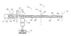
- FIG. 1is a side elevational view of the needle and stylet, with the needle inserted into the nerve sheath;
- FIG. 1Ais an end-on elevational view from the distal end of the needle structure, showing a detail of the tip of the needle, the tip of the stylet the and non-conductive needle material covering the region of the needle between the proximal ends;
- FIG. 1Bis a top view of the needle, with only a portion of the hub shown and the stylet removed, most of the needle being shown in section at section line 1 B- 1 B;
- FIG. 1Cis a detail of the needle tip
- FIG. 1Dis a side elevational view of the inner stylet
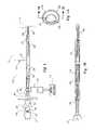
- FIG. 2is a side elevational view of the catheter
- FIG. 3is an enlarged version of FIG. 2 , except that the catheter sheath is partially cut away to better show the structure of the helical wire, only portions of which are shown;
- FIG. 4is a side elevational view of the multipurpose connector in section, with the proximal end of the catheter inserted therein but not yet rigidly held in place;
- FIG. 5is a perspective view of the metal washer, multipurpose connector wires and sealing assembly of the multipurpose connector
- FIG. 6is a side elevational view of the metal washer, multipurpose connector wires and sealing assembly of the multipurpose connector
- FIG. 7is a side elevational view of an alternate embodiment of the multipurpose connector, with the proximal end of the catheter inserted therein but not yet rigidly held in place and the distal end of the catheter also shown with much of the intervening catheter cut away;
- FIG. 8is a side cross-sectional view of an alternate embodiment of the multipurpose connector in section, with the proximal end of the catheter inserted therein but not yet rigidly held in place;
- FIG. 9is a side elevational view of the catheter disclosing some inner structures therein in partial cross-section, an electrical connection hub and an electrical connection plug;
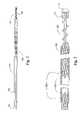
- FIG. 10Ais an side elevational detail of the slug type distal tip shown inserted into the distal end of an alternate version of the catheter, the catheter is in section;
- FIG. 10Bis cross sectional detail view of the helical support wire of the catheter showing the electrically insulating coating disposed thereon as discussed in reference to an alternate embodiment
- FIG. 10Cis a side elevational detail of an alternate embodiment of the slug type distal tip shown inserted into the distal end of an alternate version of the catheter, the catheter is in section;
- FIG. 11is a perspective view of a first embodiment of a catheter lock shown in the unlocked position
- FIG. 12is a perspective view of the first embodiment of the catheter lock shown in the locked position
- FIG. 13is an end-on view of the first embodiment of catheter lock shown in the unlocked position
- FIG. 14is an end-on view of the first embodiment of catheter lock shown in the locked position
- FIG. 15is an exploded detail view the first embodiment of the catheter lock showing each of the components thereof;
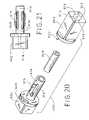
- FIG. 16is a perspective view of a second embodiment of a catheter lock shown in the unlocked position
- FIG. 17is a perspective view of the second embodiment of the catheter lock shown in the locked position
- FIG. 18is an end-on view of the second embodiment of the catheter lock shown in the unlocked position
- FIG. 19is an end-on view of the second embodiment of the catheter lock shown in the locked position
- FIG. 20is an exploded detail view the second embodiment of the catheter lock showing each of the components thereof;
- FIG. 21is a side elevational view of the stationary body portion of the second embodiment of the catheter lock including the cylindrical extension portion thereof;
- FIG. 22is a side elevational view of the needle and stylet, with the needle inserted into the nerve sheath;
- FIG. 23is a perspective view of a tunneling device with integral gripping hub and skin bridge
- FIG. 24is a side elevational view of the needle, needle hub and catheter lock extending proximally therefrom;
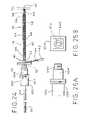
- FIG. 25Ais a side elevational view of one embodiment of the catheter lock according to the present invention.
- FIG. 25Bis an end view of one embodiment of the catheter lock according to the present invention.
- FIG. 26is a side elevational view of one embodiment of the needle hub extension for supporting structures used in controlling the electrical impulse being supplied to the patient;
- FIG. 1there is shown portions of a human body 10 containing a nerve 12 located subcutaneous to adjacent skin surface portion 14 .
- a needle assembly 16has been inserted into a human body 10 for the purpose of locating a nerve 12 .
- the stimulating needle assembly 16comprises a needle 18 and a central stylet 20 which extend coaxially of one another.
- the needle 18is a metal needle which is joined at its rear end to a hub 22 of a plastic material.
- the needle 18is hollow and projects a distance forwardly of the hub 22 .
- the needle 18has three portions along its length.
- the major portion of the needleis the central portion 24 thereof.
- This central portion 24 of the needleis wrapped on the outside surface thereof in an insulating coating 26 which will not conduct electricity.
- This coating 26is shown in FIG. 1 as being divided into sections of alternating color 28 and 30 . Each of these sections is of a known, specific, length. Such colored sectioning enables the user to determine the extent of penetration of the tip 32 of the needle 18 .
- the coating 26may be clear and the underlying surface of the needle 18 may be marked, e.g. with alternating colors or other depth markings.
- the remaining two portions of the needle 18are the distal end 34 and the proximal end 36 .
- the needle 18extends within the hub 22 where it is secured, such as by molding the hub around the needle.
- the proximal end 36 of the needle 18may be exposed such that electrical contact with the remainder of the needle may be achieved by contact with the exposed proximal end 36 .
- the bore through the needle 38opens into an axially-aligned bore 40 through the hub 22 of the same diameter as the needle bore 38 .
- the rear end of the bore 42is enlarged and tapered to provide a female Luer opening 44 for use in receiving the stylet 20 and stylet hub 21 .
- the hub 22is provided with an axially-extending slot or keyway 25 formed in the outer surface of the hub, on that side of the hub to which the tip 32 of the needle 18 is inclined.
- the distal end 31 of the needle 18is bent downwardly, the distal end 34 of the needle being cut such that it makes an angle ⁇ with the axis of the major part of the needle.
- This inclined end of the needleprovides it with a tip 32 constituting a sharp point that readily pierces body tissue.
- the distal end 34 of the needleis not covered by any electrically insulating material and is in electrical contact, by way of the covered central portion 24 , with the proximal end 36 of the needle.
- the insulating coating 26prevents the flow of electricity radially out of the central portion 24 of the needle, but allows the flow of electricity axially along the length of the needle 18 .
- the inner stylet 20is formed of a solid metal needle.
- the distal tip 45 of the stylet 20is cut to have the same sharp tip angle ⁇ as the tip 32 of the needle.
- a stylet hub 21 of plastic materialJoined to the proximal end of the stylet 20 is a stylet hub 21 of plastic material.
- the stylet 20is smaller in diameter than the outer needle 18 .
- the connector 46 of the stylet hub 21 which grasps the stylet 20is of generally cylindrical shape.
- the forward end of the connector 46has a Luer taper 48 that is dimensioned to fit within the Luer-tapered opening 44 in the needle hub 22 .
- a short peg or key 50 of rectangular sectionis provided along the lower side of the stylet hub 21 , as viewed in FIG. 1 .
- the peg 50extends axially of the stylet hub 21 , being spaced outwardly by a small gap from its Luer-tapered section 48 .
- the peg 50is aligned with respect to the stylet hub 21 and stylet 20 such that, when the peg is engaged in the slot 25 of the needle hub 22 , the plane of the inclined tip 45 of the stylet 20 lies in the same plane as the inclined tip 34 of the needle.
- the combined sharp tips of the needle and styletreadily pierces body tissue while the stylet, occupying the center bore 38 of the needle, prevents any tissue from entering the needle bore 38 .
- an electrical connector 52which may be in the form of an alligator clip which conveys electrical impulses from an anaesthetic nerve stimulator 17 to the proximal end of the needle 36 .
- FIG. 1Ais an end on view of the tip of the needle assembly 16 , showing the inclined tip of the needle 32 and the inclined tip 45 of the stylet 20 . Also shown is the insulating coating 26 .
- FIG. 1Bis a detail of the needle 18 of the needle assembly, with the stylet 20 removed and only showing a small portion of the hub 22 .
- the needle 18 of FIG. 1has been sectioned along section line 1 B of FIG. 1A .
- FIG. 1Bshows the relationship of the insulating coating 26 (of exaggerated thickness) to the various portions of the needle 18 .
- the catheter assembly 54is of a diameter which allows the assembly to be inserted through the needle assembly 16 and into the body of the patient.
- the catheter assembly 54is primarily defined by a sheath 56 formed from a thermoplastic or similar material.
- a helical coil of wire 58may also be utilized in conjunction with catheter sheath 56 .
- helical wire 58possesses three portions. A proximal portion 60 , a central portion 62 and a distal portion 64 .
- catheter assembly 54defines a central bore 66 through which a liquid may freely pass.
- the helical wire 58occupies only the peripheral portion of the central bore 66 , thus maintaining the presence of central bore 66 .
- This central bore 66can also be seen to be extended beyond the catheter sheath by the presence of the helical wire 58 .
- the helical wire 58is not a necessary element of the catheter assembly 54 . Rather, the helical wire can be eliminated, especially where the catheter is of sufficient strength so as to support itself.
- Ribbon wire 57has two primary functions. The first of these functions is to prevent wire helix 58 , if present, from being hyperextended. This function is accomplished by rigidly attaching ribbon wire 57 to distal tip 72 , discussed more fully below, and to the proximal portion 60 of the helical wire 58 . Attachment of the ribbon wire 57 at these portions of the helical wire will prevent the helix from being stretched in such a way as to permanently deform the wire. The second function of the ribbon wire 57 is to conduct electricity from the proximal portion of the catheter to the distal tip 72 of the catheter.
- This conduction of electricitymay be supplemental to the electrical conduction of the wire helix 58 or it may be as an alternative to the electrical conduction provided by the wire helix.
- This interchangeabilityis obvious, given the fact that the wire helix 58 and the ribbon wire 57 both extend from the proximal end of the catheter to the distal tip 72 .
- the wire helix 58 and the ribbon wire 57are alternatives for conducting an electrical impulse from one end of the catheter assembly 54 to the other. If one of these two wires is present to accomplish this, there is no need for the other one.
- the central portion 62 of the helical wire 58is completely covered by the catheter sheath 56 .
- the proximal portion 60 of the helical wirehas no distinguishing features except that it is short relative to the central portion of the remainder of the catheter assembly 54 and is not covered by the catheter sheath.
- Proximal portion 60 of helical wire 58can be electrically contacted. This can be accomplished by leaving it exposed as in FIG. 2 or by providing an electrical contact such as a wire, as will be discussed below.
- the wire coilmay be covered with an insulating material 59 other than or in addition to the thermoplastic cover provided by the catheter sheath 56 .
- This additional insulating material 59e.g. PTFE (Polytetrafluoroethylene) “TEFLON”, surrounds the entire circumference of the wire as it is formed, prior to being coiled.
- the thin insulating coating 59can be applied after the wire is formed into a helical coil.
- Such an insulating material 59is typically much thinner than the thermoplastic cover applied to the entire coil after the wire coil is formed.
- such an insulating material 59is typically directly bonded to the surface of the wire.
- the wire helix 58 and other portions of the present apparatuswhich are electrically conducting and may come in contact with the tissues of a patient with an insulating material it becomes possible to very precisely control the size and location of the conducting portions of the apparatus. This control is accomplished by removing the thin insulating material 59 only from the precise portions of the apparatus which are to deliver electrical impulses to the tissues of a patient. In addition, with only the relatively small portion of the conducting portions of the apparatus exposed, the voltage density achieved at that point is high relative to the power of the electrical impulse supplied.
- the distal portion 64 of the helical wirewhich is short relative to the remainder of the catheter assembly 54 and not covered by the catheter sheath 56 , has several features associated therewith.
- the helical wire 58exits the catheter sheath 56 at the distal end thereof, the helix maintains the tightly wound nature of the proximal 60 and central 62 portions of the wire. This tight helix continues for a short distance before the helix opens up at an open helix portion 68 .
- the open helix portion 68continues for several revolutions of the helix, before the tightly wound structure returns for the distal end 70 of the distal portion 64 .
- Attached to the distal end 70is a distal tip 72 which is a piece of rounded metal.
- distal tip 72may also or alternatively have ribbon wire 57 attached thereto.
- the distal tipis conducting and can either be completely bare of insulation or be substantially covered with thin layer 59 of insulating material, e.g. PTFE, and have a specific portion uninsulated.
- a catheter packaging clipmay be provided for retaining catheter 54 to prevent rapid uncoiling.
- the catheter packaging clipmay have a surface for gripping the clip as well as integral tunnel for retaining catheter 54 in such a way that rapid uncoiling can be prevented.
- a catheter packaging clipmay have dual gripping portions but a tunnel similar to that of the alternate embodiment. The clip may be packaged with the catheter 54 .
- a catheter adapter 74Accessing the central bore 66 of the catheter assembly 54 would be nearly impossible given the diameter of this structure. This being the case, a catheter adapter 74 is needed to provide access to the central bore 66 of the catheter assembly 54 for various delivery vehicles, e.g. a syringe, for the controlled delivery of fluid through the catheter.
- various delivery vehiclese.g. a syringe
- the main constituents of the catheter adapterare the rear body 76 , the front body 78 and the holding hub 80 .
- the rear body 78has a central flange 82 . From the rear face 84 of the central flange 82 extends a connection cylinder 86 having a threaded outer surface 88 and a hollow central bore 90 . The function of this cylinder is to facilitate luer attachment of apparatus for controlled delivery of fluid to the catheter assembly 54 .
- the end cap 92 provided with the catheter adapter 74is primarily for sterility purposes, and is simply removed after the catheter adapter 74 is attached to the catheter assembly 54 .
- the central flangehas, at its center, a bore 93 passing completely therethrough such that the rear face 84 and front face 94 are in fluid communication.
- an operating cylinder 96From the front face 94 of the central flange 84 extends an operating cylinder 96 . Where the operating cylinder 96 is connected to the front face 94 of the central flange 84 , it is of a certain diameter 95 . Along the length of the operating cylinder, the diameter of the operating cylinder is reduced by a taper 98 . The remainder of the operating cylinder is of this reduced diameter 99 to the distal end 100 of the operating cylinder.
- the operating cylinder 96has a central bore 102 which extends along the entire length thereof. Axial slots 104 extend from the distal end 100 of the operating cylinder, nearly the length thereof, i.e.
- the slot ends 106extend nearly to the juncture of the operating cylinder 96 and the front face 94 of the central flange 82 .
- Contained in and extending most of the length of the central bore 102 of the operating cylinder 96is an elongated rubber gasket 105 .
- the front body 78 of the catheter adapterhas a structure similar in geometry to the central flange 84 of the rear body 76 , this structure is called the rear flange 110 .
- the rear flange 110has extending from the front face 112 thereof a front cylinder 114 .
- the front cylinder 114has an essentially constant outside diameter extending from the front face 112 of the rear flange 110 to the distal end 116 of the front cylinder.
- a central bore 118is provided in the front cylinder 114 , extending the entire length thereof. This central bore 118 has several different diameter changes along its length.
- the diameter of the boreis slightly larger that the diameter 95 of the operating cylinder 96 where it is connected to the front face 94 of the central flange 84 .
- the inside diameteris reduced by a taper 123 which is a mirror image of taper 98 on the operating cylinder.
- the holding hub 80is a generally tubular body provided with a cylindrical recess 126 formed in the rear face 128 thereof.
- the distal end 100 of the operating cylinder 96is matingly engageable with the cylindrical recess 128 of the holding hub 80 and is rigidly attached thereto.
- the diameter of the central bore 120 of the front body 78is, from the front face thereof 94 to a depth less than the length of the holding hub, slightly greater than the diameter of the holding hub.
- the rigid connection between the holding hub 80 and the distal end 100 of the operating cylinderholds these two structures in slidable relationship with the front body 78 .
- the catheter adapter 74is initially in the configuration shown in FIG. 4 .
- the proximal end 60 of the catheter assembly 54may be freely inserted and withdrawn from the catheter adapter.
- the proximal end 60 of the catheter assembly 54may be held in place by sliding the front body 78 toward the rear body 76 of the catheter adapter.
- the taper 98 of the operating cylinder 96will be compressed by the taper 123 of the interior of the front body.
- the slots 104 in the operating cylinder 96allow this compression to occur.
- the compression of the operating cylinderresults in the compression of the elongated rubber gasket 105 .
- This compression of the elongated rubber gasket 105results in the rubber gasket frictionally engaging the proximal end 60 of the catheter assembly 54 such that the catheter may not be easily removed from the catheter adapter.
- An additional structure of this embodiment of the catheter adapter which is of interestis the metal washer 130 .
- This metal washer 130is disposed about the operating cylinder 96 adjacent the front face 94 of the central flange 82 . Seal 132 prevents leakage of fluid adjacent the metal washer 130 .
- the metal washer 130is provided with a tab portion 134 which extends above the flange portions 84 and 110 . This allows electrical contact to be made to the washer by way of the same electrical connector 52 as was used previously to conduct electricity into the needle assembly 16 from an anaesthetic nerve stimulator 17 .
- a pair of wires 138are attached to the metal washer 130 and extend from the metal washer to the internal bore 140 of the elongated rubber gasket 105 .
- FIG. 22there is shown relevant portions of a human body 10 containing a nerve 12 located subcutaneous to a skin surface portion 14 .
- a needle assembly 16has been inserted into a specific point in the skin surface portion 14 of the human body 10 for the purpose of locating a nerve 12 .
- the needle assembly 16comprises a needle 18 and a central stylet 20 which extend coaxially of one another.
- the needle 18is a metal needle which is joined at its rear end to a hub 22 of a plastic material.
- the needle 18is hollow and projects forwardly of the hub 22 .
- the needle 18has three portions along its length.
- the major portion of the needleis the central portion 24 thereof.
- This central portion 24 of the needleis wrapped on the outside surface thereof with an insulating coating 26 which will not conduct electricity.
- This coating 26is shown in FIG. 22 as being divided into sections of alternating color 28 and 30 . Each of these sections is of a known, specific, length. Such colored sectioning enables the user to determine the extent of penetration of the tip 32 of the needle 18 .
- the remaining two portions of the needle 18are the distal end 34 and the proximal end 36 .
- the needle 18extends within the hub 22 where it is secured, such as by molding the hub around the needle.
- the proximal end 36 of the needle 18 extending outside of the hub 22is covered with insulating coating 26 .
- the bore extending through the needle 38opens into an axially-aligned bore 40 extending through the hub 22 having the same diameter as the needle bore 38 .
- the rear end of the bore 40is enlarged and tapered to provide a female Luer opening 44 for use in receiving the stylet 20 and stylet hub 21 .
- a connection wire 144is provided which extends through the hub 22 and is electrically connected within the hub to the needle 38 .
- connection plug 142is provided on the external end of the connection wire 144 . This connection plug 142 allows the connection wire 144 to be easily connected to a nerve stimulator apparatus 17 .
- the distal end 34 of the needleis not covered by any electrically insulating material and is in electrical contact, by way of the covered central portion 24 , with the portion of the needle which is connected to the connection wire 144 .
- the insulating coating 26prevents the flow of electricity radially out of the central portion 24 and proximal portion 36 of the needle, but allows the flow of electricity axially along the length of the needle 18 .
- the inner stylet 20is of the same construction as described with respect to FIGS. 1 and 1D .
- the catheter assembly 54is essentially the same as described previously and of a diameter which allows the assembly to be inserted through the needle assembly 16 and into the body of the patient.
- the cathetercomprises a sheath 56 formed from a thermoplastic or similar material.
- the helical wire 58 and sheath 56define a central bore 66 through which a liquid may freely pass.
- connection hub 174 of the embodiment shown in FIG. 9is able to frictionally engage the proximal end of the catheter 54 especially the portion of the catheter sheath 56 adjacent the proximal end 60 of the helical wire.
- the connection hub 174slidably receives and frictionally holds the proximal end of the catheter 56 .
- the electrical connector 176is formed from a conductive material and acts as a physical and electrical connector between the electrical cable 172 and the catheter stylet 178 which in turn is electrically in contact with much of the length of the helical coil 60 and the safety ribbon wire 57 .
- connection hub 174which is made of an insulating material. Insulated connection wire 172 is also rigidly connected to the electrical connector 176 at connection point 180 .
- connection wire 172allows an electrical voltage to be conducted from the connection plug 170 to the electrical connector 176 and the helical wire 58 .
- the connection plugis dimensioned so as to be able to be connected to a voltage source such as the nerve stimulator 17 ( FIG. 1 ).
- central stylet 178is rigidly connected to electrical connector 176 at point 182 and extends, when the catheter is frictionally retained by the connection hub 174 , through the central bore 66 of the catheter 54 for the majority of the length of the catheter 54 .
- Stylet distal end 179is shown in FIG. 9 .
- the central styletis a long wire structure which is of such a material so as to provide extra rigidity to the catheter during the time when such rigidity is needed, i.e. prior to and during insertion of the catheter 54 .
- central stylet 178 and ribbon wire 57are both present in the catheter lumen 66 .
- Central stylet 178extends from where it attaches to electrical connector 176 at point 182 to its distal end 179 not rigidly attached to any other structure.
- Ribbon wire 57as described above, has a distal end rigidly connected to distal tip 72 and a proximal end rigidly connected to the proximal end 60 of the catheter assembly 54 .
- the distal portion 64 of the helical wire 58is short relative to the remainder of the catheter assembly 54 and not covered by the catheter sheath 56 .
- Attached to the distal end of the catheter 54is conductive distal tip 72 which is a piece of rounded metal. Conductive distal tip 72 is electrically contacted to the nerve stimulator through the intervening structures, whether through the wire coil 58 or the ribbon wire 57 .
- a catheter adapter 74Accessing the central bore 66 of the catheter assembly 54 would be difficult given the diameter of this structure. This being the case, a catheter adapter 74 is used to provide access to the central bore 66 of the catheter assembly 54 for various delivery vehicles, e.g. a syringe, for the controlled delivery of fluid through the catheter.
- various delivery vehiclese.g. a syringe
- the main constituents of the catheter adapterare the rear body 76 , the front body 78 and the holding hub 80 .
- the rear body 76has a central flange 82 . From the rear face 84 of the central flange 82 extends a connection cylinder 86 .
- the function of this cylinder 86is to facilitate attachment of a source of fluid to allow controlled delivery of the fluid to the central bore 66 of the catheter assembly 54 .
- the end cap 92 provided over the connection cylinder 86is primarily for sterility purposes and is simply removed after the catheter adapter 74 is attached to the catheter assembly 54 .
- the central flange 82has, at its center, a bore 93 passing completely therethrough such that the rear face 84 and front face 94 are in fluid communication.
- FIGS. 7 and 8From the central flange 84 extends an operating cylinder 96 .
- the front body portion 78 of the catheter adapter 74is disposed about the operating cylinder 96 .
- the operation of the catheter adapter depicted in FIGS. 7 and 8is identical to the operation of the catheter adapter discussed previously and depicted in FIG. 4 .
- One difference in the embodiment depicted in FIGS. 7 and 8is that a connection wire 144 passes through the operating cylinder 96 . This connection wire 144 is insulated except where it enters the operating cylinder 96 .
- connection wire 144When the proximal end 60 of the catheter 54 is disposed in the central bore 102 of the operating cylinder 96 , the wire coil 58 and/or the ribbon wire 57 of the catheter 54 are brought into electrical contact with the connection wire 144 , either directly or through an intervening conducting structure, e.g. like a metal nut or washer.
- the end of the connection wire 144 which extends outside the operating cylinder 96is connected to a connection plug 142 which can be plugged into a device 17 for supplying a stimulating voltage.
- FIG. 10Adiscloses an alternative embodiment of the distal end 64 of the catheter assembly 54 .
- the insulating thermoplastic sheath 56ends prior to the distal end 64 of the catheter and the helical wire coil 58 opens its helix 68 before it terminates at conductive distal tip 72 .
- the conductive distal tip 72is replaced with a slug type distal tip 150 .
- the insulating thermoplastic sheath 56 of the catheter assembly 54extends past, i.e. distally of, the distal end of the wire helix 58 .
- the slug type distal tip 150has three main sections of respectively increasing diameter; the cylinder 158 sized to receive the wire coil 58 , the center cylinder 156 sized to receive the thermoplastic sheath 54 and the distal cylinder 157 which is of greater diameter than either the inside diameter of the thermoplastic sheath 56 or the wire coil 58 thus avoiding being inserted too far into the catheter 54 .
- Passage 152passes entirely through the slug type distal tip 150 , exiting at the distal exit 154 of the slug type distal tip 150 .
- the central bore 66 of the catheter assembly 54is still provided with an outlet through which medicine or other fluids can pass.
- FIG. 10Bshows a cross section of helical wire 58 having disposed thereon a thin layer of insulating material 59 , e.g. PTFE (TEFLON).
- the thin layer of insulating material 59can be disposed over the entire surface of the wire either before or after the wire is formed into a helix.
- the portions of the helical wire 58 that are desired to be exposed and, thus, capable of conducting electricity beyond the wire helix,may be easily stripped of the thin insulating coating 59 by any of a number of standard methods.
- FIG. 10CShown in FIG. 10C is an alternative embodiment of the slug type distal tip 150 .
- the passage 152 , cylinder 158 and distal exit 154 of the slug type distal tip 150are eliminated.
- the slug type distal tip 150is solid and cannot pass fluid therethrough.
- a slight modification of the wire coil 58 and thermoplastic sheath 56allow passage of the fluid.
- the helix of the wire coil 58is again opened 160 as in other embodiments, e.g. FIG. 9 , and radial channels 162 are formed in the thermoplastic sheath 58 adjacent the open helices 160 .
- fluid flowwould be allowed from the central bore 66 of the catheter 54 out through the open helices 160 and through the radial channels 162 into the patient.
- the ribbon wire 57can either be rigidly connected to the proximal end of slug type distal tip 150 or rigidly connected to the distal end of wire helix 58 . Any configuration which allows the wire helix and/or the ribbon wire to conductively contact slug type distal tip 150 is appropriate.
- the concentration of the applied voltage in a specific locationis relatively small when compared with other embodiments, where both the wire helix 58 and the conductive distal tip 72 were made of conductive materials. This concentration of the applied voltage should result in easier and more precise placement of the catheter and, thus, the fluid supplied by said catheter.
- FIGS. 11-15disclose one embodiment for a cylindrical catheter lock 200 for use with the above described device.
- the function of the catheter lock 200is to allow the catheter 54 to pass freely through the central bore of the catheter lock until it is desired to have the catheter firmly grasped by the catheter lock. This firm grasping by the catheter lock 200 of the catheter 54 is accomplished by an actuation of the catheter lock, the structure and functioning of which will be described in detail below.
- Catheter lock 200is made up of four main components.
- Stationary cylinder 202is the portion of the catheter lock which supports the remaining components; stationary cylinder 202 is comprised of a large diameter portion 213 and a lesser diameter portion 214 , which is coaxial with the large diameter portion 213 .
- Rotatable cylinder 204is disposed over the lesser diameter portion 214 of stationary cylinder 202 .
- Compressible sleeve 208is fully contained within the central bore of the lesser diameter portion 214 of the stationary cylinder 202 .
- the fourth main componentis the compressing cylinder 210 which is disposed in hole 216 in the lesser diameter portion 214 of the stationary cylinder 202 .
- Stationary cylinder 202has an axial bore extending through its entire length.
- the axial bore in the lesser diameter portion 214 of the stationary cylinder 202is sized to fit the compressible sleeve 208 .
- the axial bore 218 in the remainder of the stationary cylinder 202is sized to slidably fit the catheter 54 .
- the axial bore in the rotatable cylinder 204is sized to fit the lesser diameter portion 214 of the stationary cylinder 202 .
- a recess 212 in the inner wall of the rotatable cylinder 204is sized to fit a portion of the compressing cylinder 210 .
- the compressing cylinder 210When the components of the catheter lock 200 are fit together in the unlocked position shown in FIGS. 11 and 13 , the compressing cylinder 210 is located in the hole 216 in the lesser diameter portion 214 of the stationary cylinder 202 .
- the resilient nature of the compressible sleeve 208causes the compressing cylinder 210 to be forced up into the recess 212 when the two are in alignment, as in the unlocked position. In the unlocked configuration the catheter lock 200 can freely slide along the catheter 54 .
- the catheter lock 200may be twisted, made easier by a flat gripping portion 206 on the surface of the rotatable cylinder 204 , to a locked position shown in FIGS. 12 and 14 .
- the hole 216 in the lesser diameter portion 214 of the stationary cylinder 202 and the recess 212 in the rotatable cylinder 204are not in radial alignment.
- the compressing cylinder 210overcomes the resilience of the compressible sleeve 208 by the inner wall of the rotatable cylinder 204 , such that the compressible sleeve 208 is compressed by the compressing cylinder 210 when the rotatable cylinder is rotated into the locked position.
- the contact between the compressible sleeve 208 and the catheter 54becomes much more firm, such that the frictional force needed to move these elements relative to each other is much higher that it was in the unlocked position and not easily overcome.
- FIGS. 16-20A second embodiment of the catheter lock 300 is shown in FIGS. 16-20 .
- This catheter lockhas a stationary portion 302 provided with an actuating cylinder 314 .
- a boreextends through the stationary portion 302 of a diameter at least large enough to accommodate catheter 54 .
- the portion of the bore extending through the actuating cylinderis also large enough to accommodate compressible sleeve 308 .
- Compressible sleeve 308has, itself, a bore capable of slidably receiving catheter 54 .
- the lesser diameter bore of stationary portion 302is coaxial with the bore of compressible sleeve 308 when disposed in the actuating cylinder 314 .
- catheter 54is capable of passing through the catheter lock 300 .
- the actuating cylinder 314is provided with axial slots 316 therein as well as protrusions 315 thereon.
- Rotatable cylinder 304has a central bore capable of receiving actuating cylinder 314 therein.
- the cross section of the central bore of the rotatable cylinder 304receives not only the actuating cylinder 314 but also the protrusions 315 on the surface thereof, i.e. the bore has radially larger portions 312 to accommodate the protrusions 315 as well as rounded portions 313 to receive the remainder of the actuating cylinder, at least in the unlocked position shown in FIGS. 16 and 18 .
- Peg 322 on the catheter lock 300fits into groove 320 . This serves the dual purposes of indicating to the user when the catheter lock 300 is either locked or unlocked and preventing over-rotation of the rotatable portion 304 of the catheter lock 300 with respect to the stationary portion 302 .
- the catheter lock 300is attached to the proximal end of plastic needle hub 22 .
- This attachmentcan be accomplished in a number of ways. It may be useful to have the catheter lock 300 permanently attached to the plastic needle hub 22 .
- catheter lockcould be physically welded, glued or otherwise permanently attached to the plastic needle hub.
- catheter lock 300could be provided with an integral connector 330 capable of mateable, removable connection to the plastic needle hub 22 .
- FIGS. 25A and 25Bdisclose integral connectors 330 on catheter lock 300 capable of mateably, removably connecting to suitable structures which could easily be supplied on plastic needle hub 22 . Numerous such connectors are well known in the art.
- catheter lock 200could be substituted in the alternate embodiment shown in FIG. 24 .
- U.S. Pat. No. 5,830,151 to Hadzic et al.discloses “APPARATUS FOR LOCATING AND ANESTHETIZING PERIPHERAL NERVES A METHOD THEREFOR” and is incorporated herein by reference.
- the Hadzic Patentdiscloses an apparatus which allows an operator to control the electrical impulse output of a nerve stimulator generally similar to the nerve stimulator 17 discussed above. This control is accomplished by way of a foot pedal.
- a potentiometer for controlling the electrical impulses from the nerve stimulator 17is provided on the needle hub 22 or an extension thereto.
- Such an extension 350 to needle hub 22is illustrated in FIG. 26 .
- Extension 350can be integral to the needle hub 22 or connected thereto in any of a number of ways, including those discussed above relative to attaching the catheter lock to needle hub 22 .
- the impulse control of the potentiometer for controlling nerve stimulator 17can take the form of any conventional switch, e.g. a wheel type switch 354 . Actuation of wheel switch 354 may control the relationship between the signal provided by the nerve stimulator and forwarded to the needle.
- the impulse control switchmay also send a signal through wire conduit 144 to nerve stimulator 17 to increase or decrease the electrical impulse strength provided by the nerve stimulator to the needle.
- a display 356may also be supported on the extension 350 . This display can take any form understandable to the user as conveying information regarding the electrical impulse being applied to the distal tip of the stimulating needle 18 .
- This display 356can be a simple digital readout or a group of LED elements.
- the display 356can present information as to the electrical impulse being supplied by nerve stimulator 17 or be a feedback, i.e. monitoring the effect of the electrical impulse on the targeted tissue 10 of the patient. This feedback may be accomplished by connecting display 356 to the targeted tissue 356 of the patient by a wire otherwise insulated from the input electrical impulse.
- Switch 358is either a mechanical or electrical switch capable of controlling the input of medicament or anaesthetic from an apparatus (not shown) connected to the connecting portion 352 of extension 350 .
- the apparatus containing the medicament to be applied to the target nerve 12 of the patientcan take numerous forms including a pump or spring loaded syringe.
- the combination of the above disclosed structures directly on or adjacent to the needle hub 22allows the medical practitioner to focus their entire attention on the most critical aspect of a procedure of this type, i.e. proper insertion of the needle 18 . There is no need for the practitioner to be distracted, either by looking away from the needle or verbally directing an assistant to increase or decrease the electronic stimulation or report as to the current strength of the stimulation being applied.
- medicamentmay be applied by the practitioner without removing a hand from the needle hub 22 which may result in an unintended shift in the placement of the needle tip.
- the above described apparatusmay be used in a number of different medical procedures.
- the following described medical procedureis one type which utilizes the features embodied in the above described apparatus.
- the methodis drawn to the correct placement of the catheter assembly 54 and, more particularly, the distal portion 64 thereof. Once the distal portion 64 of the catheter assembly 54 is determined to be in the correct position, a continuous interscalene nerve block may be administered.
- the patientis positioned in the dorsal recumbent position with the head slightly in extension and turned somewhat to the opposite side.
- An assistantapplies light traction on the arm with the elbow flexed.
- the interscalene grooveis easily palpated in this position by the following procedure: First, the posterior edge of the clavicular head of the sternocleidomastoid muscle is located; then the palpating fingers are placed postero-lateral to this muscle to identify the interscalene groove.
- the external jugular veinalmost always lies directly superficial to the interscalene groove and provides a useful additional landmark. Needle entry should be anterior or posterior to the vein.
- Another constant findingis that the interscalene groove is approximately 3 cm lateral to the most prominent portion of the belly of the sternocleidomastoid muscle at the level of the cricoid cartilage.
- the needle assembly 16is inserted into the interscalene groove at the level of the cricoid (C6 level) and the needle is directed perpendicular to the skin in all the planes.
- the needle assembly 16enters the skin at a point approximately halfway between the mastoid and the clavicle, posterior to the posterior border of the clavicular head of the sternocleidomastoid muscle.
- the point of needle entryis just caudal to the accessory nerve and just posterior to the anterior border of the posterior triangle of the neck.
- the accessory nervecan usually be identified by stimulating percutaneously with the electrical connector 52 of the nerve stimulator 17 since the nerve runs superficial to the fascial carpet of the posterior triangle of the neck, approximately midway between the clavicle and the mastoid.
- the needle assembly 16is directed caudal and parallel to the vertebrae aiming for the interscalene groove with the bevel of the needle assembly 16 directed laterally (outwards) to avoid possible central (epidural) placement of the catheter.
- All these nervesshould be avoided by redirection and/or reinsertion of the needle assembly 16 as stimulation of these nerves can provide false indications of correct needle placement that will most certainly lead to block failure or phrenic nerve paralysis if local anesthetic agent is injected at this stage.
- the central stylet 20if present, is removed from the needle 18 and the catheter assembly 54 , if not yet contained in the needle bore, is fed through the needle 18 to a point just past the tip of the needle 32 .
- Such a placement of the conductive distal tip 72is far enough so that the metal helical wire 58 does not make contact with the needle, i.e. the needle tip 32 is in contact with the catheter sheath 56 which will not conduct (disperse) electricity.
- the catheter adapter 74can be attached to the proximal end 60 of the catheter assembly 54 at this point, if it has not been attached previously.
- the electrical connector 52 of the nerve stimulator 17is then clipped to the tab portion 134 of the metal washer 130 provided on the catheter adapter 74 .
- the connection plug 142 attached to the wire 144 in contact with the catheter adapter 74is plugged into the nerve stimulator 17 .
- the output of the nerve stimulator 17can be turned down (typically to approximately 0.5-1.0 mA) as the muscle twitching will increase because all the current is now concentrated in the unsheathed helix tip 72 of the catheter assembly 54 . In an alternate embodiment of the apparatus the current is even more concentrated at the slug type distal tip 150 . Muscle contractions with a nerve stimulator 17 output of approximately 0.5 mA provides additional proof of proper placement into the sheath.
- Indwelling interscalene cathetersare notorious for falling out or dislodging.
- the same needle 16 used to place the catheteris inserted subcutaneously from just above the suprasternal notch and directed superolaterally, avoiding vascular structures, towards the point of entry of the catheter.
- the needle assembly 16is advanced to exit through the same orifice in the skin as the catheter 54 and just next to the catheter.
- the proximal end of the catheter 60is fed from the tip of the needle 32 through the needle 18 and the needle is removed so that the catheter 54 is tunneled subcutaneously. Kinking of the catheter should be avoided as the elbow formed by the catheter disappears under the skin.
- the catheteris then covered with a transparent dressing.
- FIG. 23shows such a specialized device.
- Tunneler 400is provided with a gripping hub 402 which is connected to a tunneler stylet 407 or other sharp instrument.
- a tunnel sheath 410covers the stylet over the majority of its length.
- the tunneler 400is utilized. The tunnel will typically begin somewhere near the site where the catheter 54 exits the body of the patient.
- the tip of tunneler stylet 407is inserted at this site and tunneled away from the exit site, until it is desired to end the tunnel, at which point the tip of tunneler stylet 407 is caused to exit the patient.
- the tunnelermay be removed while the tunnel sheath 410 , being completely separable from the gripping hub 402 and the tunneler stylet, remains subcutaneously tunneled inside the patient.
- the catheter 54may be inserted into the end of the sheath closest to the first catheter exit site.
- the catheter 54is easily fed through the tunnel sheath 410 until it exits the other end of the tunnel sheath 410 .
- the tunnel sheath 410may then be pulled out of the patient, leaving the catheter 54 subcutaneously tunneled, as above.
- Skin bridge 406has a central hole 409 which initially allows tunneler sheath 410 to retain the skin bridge 406 . After the tunneler stylet 407 is removed, as discussed above, the catheter 54 is then disposed through the hole 409 . The tunneler sheath may then be pulled out of the patient, leaving the catheter 54 subcutaneously tunneled, as above. Because of the placement of the skin bridge adjacent the proximal end of the tunneler 400 and the fact that the tunneler is of the forward type, the skin bridge will be retained by the catheter directly adjacent the original exit site of the catheter 54 , i.e. between the original exit and the subcutaneous tunnel. Skin bridge 406 allows increased stability of the catheter placement when anchored to the skin of the patient using standard methods. In addition, skin bridge 406 may be used as a handle for removing the catheter 54 from the patient or merely from the subcutaneous tunnel.
- anaestheticmay be administered to effectuate a nerve block:
Landscapes
- Health & Medical Sciences (AREA)
- Life Sciences & Earth Sciences (AREA)
- Surgery (AREA)
- Engineering & Computer Science (AREA)
- Nuclear Medicine, Radiotherapy & Molecular Imaging (AREA)
- Animal Behavior & Ethology (AREA)
- General Health & Medical Sciences (AREA)
- Public Health (AREA)
- Veterinary Medicine (AREA)
- Heart & Thoracic Surgery (AREA)
- Medical Informatics (AREA)
- Biomedical Technology (AREA)
- Molecular Biology (AREA)
- Anesthesiology (AREA)
- Cardiology (AREA)
- Physics & Mathematics (AREA)
- Otolaryngology (AREA)
- Plasma & Fusion (AREA)
- Pathology (AREA)
- Medicinal Chemistry (AREA)
- Chemical Kinetics & Catalysis (AREA)
- Chemical & Material Sciences (AREA)
- General Chemical & Material Sciences (AREA)
- Organic Chemistry (AREA)
- Pharmacology & Pharmacy (AREA)
- Media Introduction/Drainage Providing Device (AREA)
- Infusion, Injection, And Reservoir Apparatuses (AREA)
- Pharmaceuticals Containing Other Organic And Inorganic Compounds (AREA)
Abstract
Description
- a) Ropivacaine 10 mg/mL (1%). Inject 20 mL as a bolus and then infuse with syringe driver a diluted concentration (5 mg/mL or 0.5%) at 10-20 mL/hour. Or
- b) Bupivacaine 5 mg/mL (0.5%). Inject 20 mL as a bolus and then infuse a diluted concentration (2.5 mg/mL or 0.25%) at 10-20 mL/hour.
- a)
Ropivacaine 2 mg/mL (0.2%). Inject 10-20 mL as a bolus and then infuse the same concentration at 1-10 mL/hour. Continually adjust (titrate) the infusion rate to achieve the desired effect. Or - b) Bupivacaine 2.5 mg/mL (0.25%). Inject 10-20 mL as a bolus and the infuse the same concentration at 1-10 mL/hour. Continually adjust (titrate) the infusion rate to achieve the desired effect.
- a)
- Injection if a bolus of 30 mL bupivacaine (0.4%) via an indwelling catheter into the brachial plexus sheath at the level of the interscalene groove followed by a background infusion of bupivacaine 0.15% at a rate of 5 mL/hour and a patient-controlled bolus of 4 mL for patients weighing >65 Kg and 3 mL for patients weighing <65 Kg. A lockout time of 20 minutes was programmed into the PCA device. This seemed successful. Promising preliminary results have been achieved with ropivacaine. It seems that finer adjustment of the block to achieve varying levels and densities of motor and sensory blockade may be possible with ropivacaine.
Claims (42)
Priority Applications (14)
| Application Number | Priority Date | Filing Date | Title |
|---|---|---|---|
| US10/441,867US7386341B2 (en) | 2000-03-13 | 2003-05-20 | Instrument and method for delivery of anaesthetic drugs |
| AU2004240655AAU2004240655A1 (en) | 2003-05-20 | 2004-05-20 | Instrument and method for delivery of anaesthetic drug |
| JP2006533228AJP4738340B2 (en) | 2003-05-20 | 2004-05-20 | Equipment for anesthetic delivery |
| EP11176667AEP2409726A1 (en) | 2003-05-20 | 2004-05-20 | Instrument and method for delivery of anaesthetic drug |
| EP14174957.2AEP2915560B1 (en) | 2003-05-20 | 2004-05-20 | Instrument for delivery of anaesthetic drug |
| MXPA05012283AMXPA05012283A (en) | 2003-05-20 | 2004-05-20 | Instrument and method for delivery of anaesthetic drug. |
| EP04752721AEP1633411A4 (en) | 2003-05-20 | 2004-05-20 | Instrument and method for delivery of anaesthetic drug |
| PCT/US2004/015751WO2004103435A2 (en) | 2003-05-20 | 2004-05-20 | Instrument and method for delivery of anaesthetic drug |
| HK06112669.9AHK1092088B (en) | 2003-05-20 | 2004-05-20 | Instrument and method for delivery of anaesthetic drug |
| CA002524684ACA2524684A1 (en) | 2003-05-20 | 2004-05-20 | Instrument and method for delivery of anaesthetic drug |
| CN2004800136491ACN1838977B (en) | 2003-05-20 | 2004-05-20 | Apparatus and method for delivering anesthetic drugs |
| US11/074,515US8611993B2 (en) | 2000-03-13 | 2005-03-08 | Pre-loaded lockable stimulating catheter for delivery of anaesthetic drugs |
| ZA200508684AZA200508684B (en) | 2003-05-20 | 2005-10-26 | Instrument and method for delivery of anaesthetic drug |
| US12/101,777US7715925B2 (en) | 2000-03-13 | 2008-04-11 | Instrument and method for delivery of anaesthetic drugs |
Applications Claiming Priority (3)
| Application Number | Priority Date | Filing Date | Title |
|---|---|---|---|
| US09/524,467US6456874B1 (en) | 2000-03-13 | 2000-03-13 | Instrument for delivery of anaesthetic drug |
| US10/188,605US6973346B2 (en) | 2000-03-13 | 2002-07-02 | Instrument and method for delivery of anaesthetic drug |
| US10/441,867US7386341B2 (en) | 2000-03-13 | 2003-05-20 | Instrument and method for delivery of anaesthetic drugs |
Related Parent Applications (1)
| Application Number | Title | Priority Date | Filing Date |
|---|---|---|---|
| US10/188,605Continuation-In-PartUS6973346B2 (en) | 2000-03-13 | 2002-07-02 | Instrument and method for delivery of anaesthetic drug |
Related Child Applications (2)
| Application Number | Title | Priority Date | Filing Date |
|---|---|---|---|
| US11/074,515Continuation-In-PartUS8611993B2 (en) | 2000-03-13 | 2005-03-08 | Pre-loaded lockable stimulating catheter for delivery of anaesthetic drugs |
| US12/101,777DivisionUS7715925B2 (en) | 2000-03-13 | 2008-04-11 | Instrument and method for delivery of anaesthetic drugs |
Publications (2)
| Publication Number | Publication Date |
|---|---|
| US20040049231A1 US20040049231A1 (en) | 2004-03-11 |
| US7386341B2true US7386341B2 (en) | 2008-06-10 |
Family
ID=33476609
Family Applications (2)
| Application Number | Title | Priority Date | Filing Date |
|---|---|---|---|
| US10/441,867Expired - LifetimeUS7386341B2 (en) | 2000-03-13 | 2003-05-20 | Instrument and method for delivery of anaesthetic drugs |
| US12/101,777Expired - LifetimeUS7715925B2 (en) | 2000-03-13 | 2008-04-11 | Instrument and method for delivery of anaesthetic drugs |
Family Applications After (1)
| Application Number | Title | Priority Date | Filing Date |
|---|---|---|---|
| US12/101,777Expired - LifetimeUS7715925B2 (en) | 2000-03-13 | 2008-04-11 | Instrument and method for delivery of anaesthetic drugs |
Country Status (9)
| Country | Link |
|---|---|
| US (2) | US7386341B2 (en) |
| EP (3) | EP2915560B1 (en) |
| JP (1) | JP4738340B2 (en) |
| CN (1) | CN1838977B (en) |
| AU (1) | AU2004240655A1 (en) |
| CA (1) | CA2524684A1 (en) |
| MX (1) | MXPA05012283A (en) |
| WO (1) | WO2004103435A2 (en) |
| ZA (1) | ZA200508684B (en) |
Cited By (15)
| Publication number | Priority date | Publication date | Assignee | Title |
|---|---|---|---|---|
| US20040210295A1 (en)* | 2000-03-24 | 2004-10-21 | Stephen Brushey | Anesthesia conduction catheter for delivery of electrical stimulus |
| US20060217655A1 (en)* | 2000-03-13 | 2006-09-28 | Vitullo Jeffrey M | Pre-loaded lockable stimulating catheter for delivery of anaesthetic drugs |
| US20070213771A1 (en)* | 2006-03-07 | 2007-09-13 | Spinner Robert J | Regional anesthetic |
| US8255057B2 (en) | 2009-01-29 | 2012-08-28 | Nevro Corporation | Systems and methods for producing asynchronous neural responses to treat pain and/or other patient conditions |
| US8641677B2 (en) | 2010-01-21 | 2014-02-04 | James T. Rawls | Low-profile intravenous catheter device |
| US8805519B2 (en) | 2010-09-30 | 2014-08-12 | Nevro Corporation | Systems and methods for detecting intrathecal penetration |
| US8954165B2 (en) | 2012-01-25 | 2015-02-10 | Nevro Corporation | Lead anchors and associated systems and methods |
| US9265935B2 (en) | 2013-06-28 | 2016-02-23 | Nevro Corporation | Neurological stimulation lead anchors and associated systems and methods |
| US9308022B2 (en) | 2012-12-10 | 2016-04-12 | Nevro Corporation | Lead insertion devices and associated systems and methods |
| WO2017011664A1 (en)* | 2015-07-15 | 2017-01-19 | Teleflex Medical Incorporated | Conductive tip catheter |
| US10980999B2 (en) | 2017-03-09 | 2021-04-20 | Nevro Corp. | Paddle leads and delivery tools, and associated systems and methods |
| US11318310B1 (en) | 2015-10-26 | 2022-05-03 | Nevro Corp. | Neuromodulation for altering autonomic functions, and associated systems and methods |
| US11420045B2 (en) | 2018-03-29 | 2022-08-23 | Nevro Corp. | Leads having sidewall openings, and associated systems and methods |
| US11457903B2 (en)* | 2020-01-21 | 2022-10-04 | Pressure Products Medical Supplies, Inc. | Cardiac transseptal instruments, assemblies, and method of use of the same |
| US11590352B2 (en) | 2019-01-29 | 2023-02-28 | Nevro Corp. | Ramped therapeutic signals for modulating inhibitory interneurons, and associated systems and methods |
Families Citing this family (75)
| Publication number | Priority date | Publication date | Assignee | Title |
|---|---|---|---|---|
| US7338514B2 (en)* | 2001-06-01 | 2008-03-04 | St. Jude Medical, Cardiology Division, Inc. | Closure devices, related delivery methods and tools, and related methods of use |
| US7818053B2 (en) | 2003-02-21 | 2010-10-19 | Dtherapeutics, Llc | Devices, systems and methods for plaque type determination |
| US10172538B2 (en) | 2003-02-21 | 2019-01-08 | 3Dt Holdings, Llc | Body lumen junction localization |
| US10413211B2 (en) | 2003-02-21 | 2019-09-17 | 3Dt Holdings, Llc | Systems, devices, and methods for mapping organ profiles |
| US8078274B2 (en) | 2003-02-21 | 2011-12-13 | Dtherapeutics, Llc | Device, system and method for measuring cross-sectional areas in luminal organs |
| US7666217B2 (en)* | 2004-10-29 | 2010-02-23 | Boston Scientific Scimed, Inc. | Implantable medical endoprosthesis delivery systems and related components |
| US8784336B2 (en) | 2005-08-24 | 2014-07-22 | C. R. Bard, Inc. | Stylet apparatuses and methods of manufacture |
| US8388546B2 (en) | 2006-10-23 | 2013-03-05 | Bard Access Systems, Inc. | Method of locating the tip of a central venous catheter |
| US7794407B2 (en) | 2006-10-23 | 2010-09-14 | Bard Access Systems, Inc. | Method of locating the tip of a central venous catheter |
| US8282599B2 (en)* | 2006-12-08 | 2012-10-09 | Boston Scientific Scimed, Inc. | Therapeutic catheter with displacement sensing transducer |
| US20080183188A1 (en)* | 2007-01-25 | 2008-07-31 | Warsaw Orthopedic, Inc. | Integrated Surgical Navigational and Neuromonitoring System |
| US20080183068A1 (en)* | 2007-01-25 | 2008-07-31 | Warsaw Orthopedic, Inc. | Integrated Visualization of Surgical Navigational and Neural Monitoring Information |
| US20080183074A1 (en)* | 2007-01-25 | 2008-07-31 | Warsaw Orthopedic, Inc. | Method and apparatus for coordinated display of anatomical and neuromonitoring information |
| US8374673B2 (en)* | 2007-01-25 | 2013-02-12 | Warsaw Orthopedic, Inc. | Integrated surgical navigational and neuromonitoring system having automated surgical assistance and control |
| US7987001B2 (en)* | 2007-01-25 | 2011-07-26 | Warsaw Orthopedic, Inc. | Surgical navigational and neuromonitoring instrument |
| US8185205B2 (en)* | 2007-10-22 | 2012-05-22 | B. Braun Medical Inc. | Catheter switch and method of using a catheter switch in administering a nerve or plexus block |
| US9636031B2 (en) | 2007-11-26 | 2017-05-02 | C.R. Bard, Inc. | Stylets for use with apparatus for intravascular placement of a catheter |
| US10751509B2 (en) | 2007-11-26 | 2020-08-25 | C. R. Bard, Inc. | Iconic representations for guidance of an indwelling medical device |
| US10449330B2 (en) | 2007-11-26 | 2019-10-22 | C. R. Bard, Inc. | Magnetic element-equipped needle assemblies |
| US9521961B2 (en) | 2007-11-26 | 2016-12-20 | C. R. Bard, Inc. | Systems and methods for guiding a medical instrument |
| US9649048B2 (en) | 2007-11-26 | 2017-05-16 | C. R. Bard, Inc. | Systems and methods for breaching a sterile field for intravascular placement of a catheter |
| US8781555B2 (en) | 2007-11-26 | 2014-07-15 | C. R. Bard, Inc. | System for placement of a catheter including a signal-generating stylet |
| US10524691B2 (en) | 2007-11-26 | 2020-01-07 | C. R. Bard, Inc. | Needle assembly including an aligned magnetic element |
| ES2465915T3 (en) | 2007-11-26 | 2014-06-09 | C.R. Bard, Inc. | Integrated system for intravascular catheter placement |
| US8849382B2 (en) | 2007-11-26 | 2014-09-30 | C. R. Bard, Inc. | Apparatus and display methods relating to intravascular placement of a catheter |
| US7890182B2 (en) | 2008-05-15 | 2011-02-15 | Boston Scientific Neuromodulation Corporation | Current steering for an implantable stimulator device involving fractionalized stimulation pulses |
| US9901714B2 (en) | 2008-08-22 | 2018-02-27 | C. R. Bard, Inc. | Catheter assembly including ECG sensor and magnetic assemblies |
| US8437833B2 (en) | 2008-10-07 | 2013-05-07 | Bard Access Systems, Inc. | Percutaneous magnetic gastrostomy |
| US8696657B2 (en)* | 2008-12-22 | 2014-04-15 | Olympus Medical Systems Corp. | Treatment tool |
| EP2226022A1 (en)* | 2009-03-04 | 2010-09-08 | Steinbrenner, Marko | Double cannula for local anaesthetic |
| US9393382B2 (en)* | 2009-05-05 | 2016-07-19 | Robert W. Heck | High-flow tapered peripheral IV catheter with side outlets |
| US9532724B2 (en) | 2009-06-12 | 2017-01-03 | Bard Access Systems, Inc. | Apparatus and method for catheter navigation using endovascular energy mapping |
| JP5795576B2 (en) | 2009-06-12 | 2015-10-14 | バード・アクセス・システムズ,インコーポレーテッド | Method of operating a computer-based medical device that uses an electrocardiogram (ECG) signal to position an intravascular device in or near the heart |
| EP2464407A4 (en) | 2009-08-10 | 2014-04-02 | Bard Access Systems Inc | Devices and methods for endovascular electrography |
| US9168351B2 (en)* | 2009-08-26 | 2015-10-27 | Andre P. Boezaart | Instrument for continuous discharge of anesthetic drug |
| KR20110033892A (en)* | 2009-12-23 | 2011-04-01 | 신현순 | Catheter and catheter assembly |
| WO2011097312A1 (en) | 2010-02-02 | 2011-08-11 | C.R. Bard, Inc. | Apparatus and method for catheter navigation and tip location |
| US8825129B2 (en)* | 2010-03-05 | 2014-09-02 | Sri International | Indwelling nerve block catheters |
| US9955940B1 (en)* | 2010-04-23 | 2018-05-01 | Avent, Inc. | Echogenic nerve block catheter and echogenic catheter tip |
| WO2011137224A1 (en) | 2010-04-29 | 2011-11-03 | Danny Azriel Sherwinter | Systems and methods for facilitating closure of bodily openings |
| US10568628B2 (en) | 2017-05-23 | 2020-02-25 | Muffin Incorporated | Closing device for tissue openings |
| EP4122385A1 (en) | 2010-05-28 | 2023-01-25 | C. R. Bard, Inc. | Insertion guidance system for needles and medical components |
| EP2912999B1 (en) | 2010-05-28 | 2022-06-29 | C. R. Bard, Inc. | Apparatus for use with needle insertion guidance system |
| BR112013002431B1 (en) | 2010-08-20 | 2021-06-29 | C.R. Bard, Inc | SYSTEM FOR RECONFIRMING THE POSITION OF A CATHETER INSIDE A PATIENT |
| US8801693B2 (en) | 2010-10-29 | 2014-08-12 | C. R. Bard, Inc. | Bioimpedance-assisted placement of a medical device |
| US9265897B2 (en)* | 2011-01-26 | 2016-02-23 | Avent, Inc. | Method and corresponding kit for administering a paravertebral block |
| RU2609203C2 (en) | 2011-07-06 | 2017-01-30 | Си.Ар. Бард, Инк. | Determination and calibration of needle length for needle guidance system |
| KR101310716B1 (en)* | 2011-08-26 | 2013-10-14 | (주)아모레퍼시픽 | Aesthetic apparatus using high-frequency treatment |
| WO2013036705A1 (en)* | 2011-09-09 | 2013-03-14 | Spine Wave, Inc. | Apparatus for dilating bodily tissue and for monitoring neural activity in the dilated bodily tissue |
| HUE045735T2 (en)* | 2011-12-28 | 2020-01-28 | Custom Medical Applications Inc | Catheters including bend indicators, catheter assemblies including such catheters and related methods |
| JP2015516846A (en) | 2012-04-05 | 2015-06-18 | バード・アクセス・システムズ,インコーポレーテッド | Device and system for navigating and positioning a central venous catheter within a patient |
| US10159531B2 (en) | 2012-04-05 | 2018-12-25 | C. R. Bard, Inc. | Apparatus and methods relating to intravascular positioning of distal end of catheter |
| US11759268B2 (en) | 2012-04-05 | 2023-09-19 | C. R. Bard, Inc. | Apparatus and methods relating to intravascular positioning of distal end of catheter |
| CN105073173B (en)* | 2013-01-18 | 2017-05-10 | 斯坦福国际研究院 | anchored nerve block catheter |
| ITRN20130042A1 (en)* | 2013-10-09 | 2015-04-10 | Gilberto Pari | EQUIPMENT FOR ELECTROSTIMULATION OF THE NERVOUS SYSTEM AND CONTROL PROCEDURE FOR NERVOUS ELECTROSTIMULATION THERAPY |
| WO2015120256A2 (en) | 2014-02-06 | 2015-08-13 | C.R. Bard, Inc. | Systems and methods for guidance and placement of an intravascular device |
| KR20170045286A (en) | 2014-08-26 | 2017-04-26 | 아벤트, 인크. | Method and system for identification of source of chronic pain and treatment |
| US10434316B2 (en)* | 2014-09-08 | 2019-10-08 | Newpace Ltd. | Flexible rechargeable implantable subcutaneous medical device structure and method of assembly |
| US10973584B2 (en) | 2015-01-19 | 2021-04-13 | Bard Access Systems, Inc. | Device and method for vascular access |
| EP3274036B1 (en)* | 2015-03-25 | 2020-02-19 | Rigshospitalet, Copenhagen University Hospital | Balloon-tipped catheter for continuous nerve blocks |
| WO2016210325A1 (en) | 2015-06-26 | 2016-12-29 | C.R. Bard, Inc. | Connector interface for ecg-based catheter positioning system |
| US10525256B2 (en)* | 2015-07-29 | 2020-01-07 | Medtronic, Inc. | Interventional medical systems, catheters, and methods |
| CN113143355A (en)* | 2015-09-04 | 2021-07-23 | 美多斯国际有限公司 | Multi-shield spinal access system |
| US12150636B2 (en) | 2015-09-04 | 2024-11-26 | Medos International Sárl | Surgical instrument connectors and related methods |
| US10987129B2 (en) | 2015-09-04 | 2021-04-27 | Medos International Sarl | Multi-shield spinal access system |
| US11000207B2 (en) | 2016-01-29 | 2021-05-11 | C. R. Bard, Inc. | Multiple coil system for tracking a medical device |
| US10244956B2 (en) | 2016-02-12 | 2019-04-02 | Nuvectra Corporation | Stimulation needle apparatus and method |
| ES1154983Y (en)* | 2016-03-23 | 2016-07-18 | Barquero Bartolome Lajarin | NEEDLE DEVICE FOR NERVOUS LOCK |
| US10471257B2 (en)* | 2016-05-19 | 2019-11-12 | The Cleveland Clinic Foundation | Implantable temporary nerve conduction blocking method and system |
| DE102016110379A1 (en)* | 2016-06-06 | 2017-12-07 | Pajunk GmbH Medizintechnologie | Unipolar cannula |
| CN111032134B (en)* | 2017-06-30 | 2024-02-13 | 阿维塔斯有限公司 | electrospray catheter |
| CN108840047A (en)* | 2018-06-07 | 2018-11-20 | 佛山市长郡科技有限公司 | A kind of device suitable for carrying out weight feed to the fluid with pasty consistency |
| US10992079B2 (en) | 2018-10-16 | 2021-04-27 | Bard Access Systems, Inc. | Safety-equipped connection systems and methods thereof for establishing electrical connections |
| US12048826B2 (en)* | 2020-03-23 | 2024-07-30 | Becton, Dickinson And Company | Spring-based devices, systems, and methods to facilitate vascular access |
| CN112773478B (en)* | 2021-02-03 | 2025-09-09 | 中南大学湘雅二医院 | Continuous nerve block catheter delivery system and method |
Citations (37)
| Publication number | Priority date | Publication date | Assignee | Title |
|---|---|---|---|---|
| US2987292A (en) | 1959-07-13 | 1961-06-06 | William R Teson | Mechanically operated collapsible valve |
| US3550861A (en) | 1968-08-28 | 1970-12-29 | William R Teson | Hose nozzle |
| US3682162A (en) | 1968-12-13 | 1972-08-08 | Wellcome Found | Combined electrode and hypodermic syringe needle |
| DE3102142A1 (en) | 1981-01-23 | 1982-08-12 | B. Braun Melsungen Ag, 3508 Melsungen | Catheter adapter |
| US4515168A (en) | 1983-07-22 | 1985-05-07 | Chester Martin H | Clamp-on nerve stimulator and locator |
| US4518383A (en) | 1982-08-06 | 1985-05-21 | Evans John M | Instrument and method for epidural and spinal anaesthesia |
| US4540411A (en) | 1983-11-28 | 1985-09-10 | Sherwood Medical Company | Catheter placement device |
| US4644960A (en) | 1985-09-23 | 1987-02-24 | Arrow International, Inc. | Device for making electrical connection to an electrolyte, and system employing same |
| US4801293A (en) | 1985-10-09 | 1989-01-31 | Anthony Jackson | Apparatus and method for detecting probe penetration of human epidural space and injecting a therapeutic substance thereinto |
| US4824433A (en) | 1982-08-06 | 1989-04-25 | Sterimed Gesellschaft Fur Medizinischen Bedarf Mbh | Puncturing and catheterizing device for the human or animal body |
| US4973312A (en) | 1989-05-26 | 1990-11-27 | Andrew Daniel E | Method and system for inserting spinal catheters |
| US5007902A (en) | 1988-03-09 | 1991-04-16 | B. Braun Melsungen Ag | Catheter set for plexus anesthesia |
| US5081990A (en) | 1990-05-11 | 1992-01-21 | New York University | Catheter for spinal epidural injection of drugs and measurement of evoked potentials |
| US5092344A (en) | 1990-11-19 | 1992-03-03 | Lee Tzium Shou | Remote indicator for stimulator |
| US5135525A (en) | 1989-06-06 | 1992-08-04 | B. Braun Melsungen Ag | Catheter set for continuous spinal anaesthesia |
| WO1993014710A1 (en) | 1992-01-29 | 1993-08-05 | Al Rawi Muthafar Muflih | Fine gauge needles and cannulae |
| US5284153A (en) | 1992-04-14 | 1994-02-08 | Brigham And Women's Hospital | Method for locating a nerve and for protecting nerves from injury during surgery |
| US5304141A (en) | 1989-12-11 | 1994-04-19 | Brigham And Women's Hospital | Method and apparatus for inducing anesthesia |
| US5423877A (en) | 1992-05-04 | 1995-06-13 | David C. Mackey | Method and device for acute pain management by simultaneous spinal cord electrical stimulation and drug infusion |
| US5489274A (en) | 1992-10-09 | 1996-02-06 | Boston Scientific Corporation | Rotatable medical valve closure |
| EP0759307A2 (en) | 1995-08-22 | 1997-02-26 | STERIMED Medizinprodukte GmbH | Puncturing and/or catheterizing device for locating nerves |
| US5782505A (en) | 1996-08-29 | 1998-07-21 | Becton, Dickinson And Company | Catheter adapter assembly |
| WO1998033547A1 (en) | 1997-01-30 | 1998-08-06 | Mayo Foundation For Medical Education And Research | Peripheral nerve site anesthesia |
| US5830151A (en) | 1995-04-10 | 1998-11-03 | Innovative Design Associates | Apparatus for locating and anesthetizing peripheral nerves a method therefor |
| WO1999004705A1 (en) | 1997-07-25 | 1999-02-04 | Tsui Ban C H | Devices, systems and methods for determining proper placement of epidural catheters |
| US5899891A (en) | 1996-09-05 | 1999-05-04 | Epimed International, Inc. | Catheter |
| US5902273A (en) | 1997-10-15 | 1999-05-11 | Yang; Ian Y. | Pressurizable epidural space identification syringe |
| US5976110A (en) | 1998-01-14 | 1999-11-02 | Duke University | Catheter system for administration of continuous peripheral nerve anesthetic |
| EP0966922A1 (en) | 1998-06-27 | 1999-12-29 | Heinrich Pajunk | Unipolar cannula for continuous anaesthesia |
| US6104960A (en) | 1998-07-13 | 2000-08-15 | Medtronic, Inc. | System and method for providing medical electrical stimulation to a portion of the nervous system |
| US6259945B1 (en) | 1999-04-30 | 2001-07-10 | Uromed Corporation | Method and device for locating a nerve |
| US6298256B1 (en) | 1999-09-10 | 2001-10-02 | Frank-Egbert Meyer | Device and method for the location and catheterization of the surroundings of a nerve |
| US6325764B1 (en) | 1996-08-05 | 2001-12-04 | Becton, Dickinson And Company | Bi-level charge pulse apparatus to facilitate nerve location during peripheral nerve block procedures |
| US20020065481A1 (en) | 2000-11-24 | 2002-05-30 | Ckm Diagnostics, Inc. | Nerve stimulator output control needle with depth determination capability and method of use |
| US6582441B1 (en)* | 2000-02-24 | 2003-06-24 | Advanced Bionics Corporation | Surgical insertion tool |
| US20030158592A1 (en) | 2001-01-11 | 2003-08-21 | Heinrich Pajunk | Catheter for neural blockades |
| US6730083B2 (en) | 2001-05-08 | 2004-05-04 | B. Braun Melsungen Ag | Puncture cannula |
Family Cites Families (18)
| Publication number | Priority date | Publication date | Assignee | Title |
|---|---|---|---|---|
| US598923A (en)* | 1898-02-15 | Ihvento | ||
| CN87210715U (en)* | 1987-11-07 | 1988-10-26 | 单承仪 | Electric acupuncture apparatus with concentric needle |
| US4894052A (en)* | 1988-08-22 | 1990-01-16 | Becton, Dickinson And Company | Flash detection in an over the needle catheter with a restricted needle bore |
| US5190529A (en)* | 1991-05-20 | 1993-03-02 | The Kendall Company | Advancement sleeve and adapter for a catheter |
| WO1994002077A2 (en)* | 1992-07-15 | 1994-02-03 | Angelase, Inc. | Ablation catheter system |
| JP3280446B2 (en)* | 1993-02-02 | 2002-05-13 | イー. アンドリュー ダニエル | Cannula clamp |
| US5336222A (en)* | 1993-03-29 | 1994-08-09 | Boston Scientific Corporation | Integrated catheter for diverse in situ tissue therapy |
| US5807395A (en)* | 1993-08-27 | 1998-09-15 | Medtronic, Inc. | Method and apparatus for RF ablation and hyperthermia |
| US5599346A (en)* | 1993-11-08 | 1997-02-04 | Zomed International, Inc. | RF treatment system |
| CN1177507A (en)* | 1996-08-05 | 1998-04-01 | 贝克顿迪金森公司 | Needle assembly for electrically stimulating nerve |
| IT1291483B1 (en)* | 1997-01-31 | 1999-01-11 | Hospal Dasco Spa | HYDRAULIC CIRCUIT FOR A HEMODIALYSIS LIQUID, IN PARTICULAR OF A DIALIZING LIQUID. |
| US6086582A (en)* | 1997-03-13 | 2000-07-11 | Altman; Peter A. | Cardiac drug delivery system |
| CN2316969Y (en)* | 1998-01-19 | 1999-05-05 | 吴成富 | Intravertebral spinal peridural anesthesia therapeutic equipment |
| US8079982B1 (en)* | 1998-06-04 | 2011-12-20 | Biosense Webster, Inc. | Injection catheter with needle electrode |
| US6579279B1 (en)* | 1999-09-24 | 2003-06-17 | Omnisonics Medical Technologies, Inc. | Steerable catheter device |
| US6456874B1 (en)* | 2000-03-13 | 2002-09-24 | Arrow International Inc. | Instrument for delivery of anaesthetic drug |
| US20020087152A1 (en)* | 2001-01-04 | 2002-07-04 | Endocare, Inc. | Systems and methods for delivering a probe into tissue |
| US6554809B2 (en)* | 2001-08-02 | 2003-04-29 | Teodulo Aves | Epidural catheter needle |
- 2003
- 2003-05-20USUS10/441,867patent/US7386341B2/ennot_activeExpired - Lifetime
- 2004
- 2004-05-20CACA002524684Apatent/CA2524684A1/ennot_activeAbandoned
- 2004-05-20MXMXPA05012283Apatent/MXPA05012283A/enactiveIP Right Grant
- 2004-05-20EPEP14174957.2Apatent/EP2915560B1/ennot_activeExpired - Lifetime
- 2004-05-20WOPCT/US2004/015751patent/WO2004103435A2/enactiveApplication Filing
- 2004-05-20JPJP2006533228Apatent/JP4738340B2/ennot_activeExpired - Fee Related
- 2004-05-20EPEP04752721Apatent/EP1633411A4/ennot_activeWithdrawn
- 2004-05-20AUAU2004240655Apatent/AU2004240655A1/ennot_activeAbandoned
- 2004-05-20CNCN2004800136491Apatent/CN1838977B/ennot_activeExpired - Fee Related
- 2004-05-20EPEP11176667Apatent/EP2409726A1/ennot_activeWithdrawn
- 2005
- 2005-10-26ZAZA200508684Apatent/ZA200508684B/enunknown
- 2008
- 2008-04-11USUS12/101,777patent/US7715925B2/ennot_activeExpired - Lifetime
Patent Citations (40)
| Publication number | Priority date | Publication date | Assignee | Title |
|---|---|---|---|---|
| US2987292A (en) | 1959-07-13 | 1961-06-06 | William R Teson | Mechanically operated collapsible valve |
| US3550861A (en) | 1968-08-28 | 1970-12-29 | William R Teson | Hose nozzle |
| US3682162A (en) | 1968-12-13 | 1972-08-08 | Wellcome Found | Combined electrode and hypodermic syringe needle |
| DE3102142A1 (en) | 1981-01-23 | 1982-08-12 | B. Braun Melsungen Ag, 3508 Melsungen | Catheter adapter |
| US4518383A (en) | 1982-08-06 | 1985-05-21 | Evans John M | Instrument and method for epidural and spinal anaesthesia |
| US4824433A (en) | 1982-08-06 | 1989-04-25 | Sterimed Gesellschaft Fur Medizinischen Bedarf Mbh | Puncturing and catheterizing device for the human or animal body |
| US4515168A (en) | 1983-07-22 | 1985-05-07 | Chester Martin H | Clamp-on nerve stimulator and locator |
| US4540411A (en) | 1983-11-28 | 1985-09-10 | Sherwood Medical Company | Catheter placement device |
| US4644960A (en) | 1985-09-23 | 1987-02-24 | Arrow International, Inc. | Device for making electrical connection to an electrolyte, and system employing same |
| US4801293A (en) | 1985-10-09 | 1989-01-31 | Anthony Jackson | Apparatus and method for detecting probe penetration of human epidural space and injecting a therapeutic substance thereinto |
| US5007902A (en) | 1988-03-09 | 1991-04-16 | B. Braun Melsungen Ag | Catheter set for plexus anesthesia |
| US4973312A (en) | 1989-05-26 | 1990-11-27 | Andrew Daniel E | Method and system for inserting spinal catheters |
| US5135525A (en) | 1989-06-06 | 1992-08-04 | B. Braun Melsungen Ag | Catheter set for continuous spinal anaesthesia |
| US5304141A (en) | 1989-12-11 | 1994-04-19 | Brigham And Women's Hospital | Method and apparatus for inducing anesthesia |
| US5081990A (en) | 1990-05-11 | 1992-01-21 | New York University | Catheter for spinal epidural injection of drugs and measurement of evoked potentials |
| US5092344A (en) | 1990-11-19 | 1992-03-03 | Lee Tzium Shou | Remote indicator for stimulator |
| US5989223A (en) | 1991-10-11 | 1999-11-23 | Boston Scientific Corporation | Rotatable medical valve closure |
| WO1993014710A1 (en) | 1992-01-29 | 1993-08-05 | Al Rawi Muthafar Muflih | Fine gauge needles and cannulae |
| US5284153A (en) | 1992-04-14 | 1994-02-08 | Brigham And Women's Hospital | Method for locating a nerve and for protecting nerves from injury during surgery |
| US5423877A (en) | 1992-05-04 | 1995-06-13 | David C. Mackey | Method and device for acute pain management by simultaneous spinal cord electrical stimulation and drug infusion |
| US5489274A (en) | 1992-10-09 | 1996-02-06 | Boston Scientific Corporation | Rotatable medical valve closure |
| US5830151A (en) | 1995-04-10 | 1998-11-03 | Innovative Design Associates | Apparatus for locating and anesthetizing peripheral nerves a method therefor |
| EP0759307A2 (en) | 1995-08-22 | 1997-02-26 | STERIMED Medizinprodukte GmbH | Puncturing and/or catheterizing device for locating nerves |
| US6325764B1 (en) | 1996-08-05 | 2001-12-04 | Becton, Dickinson And Company | Bi-level charge pulse apparatus to facilitate nerve location during peripheral nerve block procedures |
| US5782505A (en) | 1996-08-29 | 1998-07-21 | Becton, Dickinson And Company | Catheter adapter assembly |
| US5899891A (en) | 1996-09-05 | 1999-05-04 | Epimed International, Inc. | Catheter |
| WO1998033547A1 (en) | 1997-01-30 | 1998-08-06 | Mayo Foundation For Medical Education And Research | Peripheral nerve site anesthesia |
| US6190370B1 (en) | 1997-07-25 | 2001-02-20 | Arrow International, Inc. | Devices, systems and methods for determining proper placement of epidural catheters |
| WO1999004705A1 (en) | 1997-07-25 | 1999-02-04 | Tsui Ban C H | Devices, systems and methods for determining proper placement of epidural catheters |
| US5902273A (en) | 1997-10-15 | 1999-05-11 | Yang; Ian Y. | Pressurizable epidural space identification syringe |
| US5976110A (en) | 1998-01-14 | 1999-11-02 | Duke University | Catheter system for administration of continuous peripheral nerve anesthetic |
| EP0966922A1 (en) | 1998-06-27 | 1999-12-29 | Heinrich Pajunk | Unipolar cannula for continuous anaesthesia |
| US6104960A (en) | 1998-07-13 | 2000-08-15 | Medtronic, Inc. | System and method for providing medical electrical stimulation to a portion of the nervous system |
| US6259945B1 (en) | 1999-04-30 | 2001-07-10 | Uromed Corporation | Method and device for locating a nerve |
| US6298256B1 (en) | 1999-09-10 | 2001-10-02 | Frank-Egbert Meyer | Device and method for the location and catheterization of the surroundings of a nerve |
| US6582441B1 (en)* | 2000-02-24 | 2003-06-24 | Advanced Bionics Corporation | Surgical insertion tool |
| US20020065481A1 (en) | 2000-11-24 | 2002-05-30 | Ckm Diagnostics, Inc. | Nerve stimulator output control needle with depth determination capability and method of use |
| US6706016B2 (en) | 2000-11-24 | 2004-03-16 | Ckm Diagnostics, Inc. | Nerve stimulator output control needle with depth determination capability and method of use |
| US20030158592A1 (en) | 2001-01-11 | 2003-08-21 | Heinrich Pajunk | Catheter for neural blockades |
| US6730083B2 (en) | 2001-05-08 | 2004-05-04 | B. Braun Melsungen Ag | Puncture cannula |
Non-Patent Citations (3)
| Title |
|---|
| Boezaart et al., "A new technique of continuous interscalene nerve block," Canadian Journal of Anesthesia, Mar. 1999, pp. 275-281, vol. 46, No. 3, Canadian Anesthesiologists' Society Canada. |
| Sarnoff, S.J. and Sarnoff, L.C.: Prolonged Peripheral Nerve Block by Means of Indwelling Plastic Catheter Treatment of Hiccup. Dated 1950. |
| Sarnoff, S.J.: Functional Localization of Interspinal Catheters, Anesthesiology 11:300-866 (May) 1950. |
Cited By (37)
| Publication number | Priority date | Publication date | Assignee | Title |
|---|---|---|---|---|
| US8611993B2 (en)* | 2000-03-13 | 2013-12-17 | Arrow International, Inc. | Pre-loaded lockable stimulating catheter for delivery of anaesthetic drugs |
| US20060217655A1 (en)* | 2000-03-13 | 2006-09-28 | Vitullo Jeffrey M | Pre-loaded lockable stimulating catheter for delivery of anaesthetic drugs |
| US7805188B2 (en)* | 2000-03-24 | 2010-09-28 | Micor, Inc. | Anesthesia conduction catheter for delivery of electrical stimulus |
| US20100318095A1 (en)* | 2000-03-24 | 2010-12-16 | Safe Bt, Inc. | Anesthesia conduction catheter for delivery of electrical stimulus |
| US20040210295A1 (en)* | 2000-03-24 | 2004-10-21 | Stephen Brushey | Anesthesia conduction catheter for delivery of electrical stimulus |
| US20070213771A1 (en)* | 2006-03-07 | 2007-09-13 | Spinner Robert J | Regional anesthetic |
| US8027718B2 (en) | 2006-03-07 | 2011-09-27 | Mayo Foundation For Medical Education And Research | Regional anesthetic |
| US8255057B2 (en) | 2009-01-29 | 2012-08-28 | Nevro Corporation | Systems and methods for producing asynchronous neural responses to treat pain and/or other patient conditions |
| US9403013B2 (en) | 2009-01-29 | 2016-08-02 | Nevro Corporation | Systems and methods for producing asynchronous neural responses to treat pain and/or other patient conditions |
| US10179241B2 (en) | 2009-01-29 | 2019-01-15 | Nevro Corp. | Systems and methods for producing asynchronous neural responses to treat pain and/or other patient conditions |
| US10173065B2 (en) | 2009-01-29 | 2019-01-08 | Nevro Corp. | Systems and methods for producing asynchronous neural responses to treat pain and/or other patient conditions |
| US8849410B2 (en) | 2009-01-29 | 2014-09-30 | Nevro Corporation | Systems and methods for producing asynchronous neural responses to treat pain and/or other patient conditions |
| US8509906B2 (en) | 2009-01-29 | 2013-08-13 | Nevro Corporation | Systems and methods for producing asynchronous neural responses to treat pain and/or other patient conditions |
| US10918867B2 (en) | 2009-01-29 | 2021-02-16 | Nevro Corp. | Systems and methods for producing asynchronous neural responses to treat pain and/or other patient conditions |
| US11883670B2 (en) | 2009-01-29 | 2024-01-30 | Nevro Corp. | Systems and methods for producing asynchronous neural responses to treat pain and/or other patient conditions |
| US9861791B2 (en) | 2010-01-21 | 2018-01-09 | James T. Rawls | Low-profile intravenous catheter device |
| US8641677B2 (en) | 2010-01-21 | 2014-02-04 | James T. Rawls | Low-profile intravenous catheter device |
| US9358388B2 (en) | 2010-09-30 | 2016-06-07 | Nevro Corporation | Systems and methods for detecting intrathecal penetration |
| US8805519B2 (en) | 2010-09-30 | 2014-08-12 | Nevro Corporation | Systems and methods for detecting intrathecal penetration |
| US10279183B2 (en) | 2010-09-30 | 2019-05-07 | Nevro Corp. | Systems and methods for detecting intrathecal penetration |
| US8954165B2 (en) | 2012-01-25 | 2015-02-10 | Nevro Corporation | Lead anchors and associated systems and methods |
| US9308022B2 (en) | 2012-12-10 | 2016-04-12 | Nevro Corporation | Lead insertion devices and associated systems and methods |
| US10213229B2 (en) | 2012-12-10 | 2019-02-26 | Nevro Corp. | Lead insertion devices and associated systems and methods |
| US11103280B2 (en) | 2012-12-10 | 2021-08-31 | Nevro Corp. | Lead insertion devices and associated systems and methods |
| US9265935B2 (en) | 2013-06-28 | 2016-02-23 | Nevro Corporation | Neurological stimulation lead anchors and associated systems and methods |
| US9687649B2 (en) | 2013-06-28 | 2017-06-27 | Nevro Corp. | Neurological stimulation lead anchors and associated systems and methods |
| US20170014598A1 (en)* | 2015-07-15 | 2017-01-19 | Teleflex Medical Incorporated | Conductive Tip Catheter |
| US10596348B2 (en)* | 2015-07-15 | 2020-03-24 | Teleflex Medical Incorporated | Conductive tip catheter |
| WO2017011664A1 (en)* | 2015-07-15 | 2017-01-19 | Teleflex Medical Incorporated | Conductive tip catheter |
| US11318310B1 (en) | 2015-10-26 | 2022-05-03 | Nevro Corp. | Neuromodulation for altering autonomic functions, and associated systems and methods |
| US10980999B2 (en) | 2017-03-09 | 2021-04-20 | Nevro Corp. | Paddle leads and delivery tools, and associated systems and methods |
| US11759631B2 (en) | 2017-03-09 | 2023-09-19 | Nevro Corp. | Paddle leads and delivery tools, and associated systems and methods |
| US11420045B2 (en) | 2018-03-29 | 2022-08-23 | Nevro Corp. | Leads having sidewall openings, and associated systems and methods |
| US11590352B2 (en) | 2019-01-29 | 2023-02-28 | Nevro Corp. | Ramped therapeutic signals for modulating inhibitory interneurons, and associated systems and methods |
| US11457903B2 (en)* | 2020-01-21 | 2022-10-04 | Pressure Products Medical Supplies, Inc. | Cardiac transseptal instruments, assemblies, and method of use of the same |
| US20220401090A1 (en)* | 2020-01-21 | 2022-12-22 | Pressure Products Medical Supplies Inc. | Cardiac transseptal instruments, assemblies, and method of use of the same |
| US12121227B2 (en)* | 2020-01-21 | 2024-10-22 | Pressure Products Medical Supplies, Inc. | Cardiac transseptal instruments, assemblies, and method of use of the same |
Also Published As
| Publication number | Publication date |
|---|---|
| JP4738340B2 (en) | 2011-08-03 |
| US20080195034A1 (en) | 2008-08-14 |
| EP2915560B1 (en) | 2017-08-16 |
| EP1633411A2 (en) | 2006-03-15 |
| CA2524684A1 (en) | 2004-12-02 |
| EP2915560A1 (en) | 2015-09-09 |
| MXPA05012283A (en) | 2006-01-30 |
| US20040049231A1 (en) | 2004-03-11 |
| US7715925B2 (en) | 2010-05-11 |
| CN1838977A (en) | 2006-09-27 |
| WO2004103435A3 (en) | 2006-03-02 |
| WO2004103435A2 (en) | 2004-12-02 |
| JP2007502197A (en) | 2007-02-08 |
| HK1092088A1 (en) | 2007-02-02 |
| ZA200508684B (en) | 2007-02-28 |
| EP1633411A4 (en) | 2009-05-06 |
| CN1838977B (en) | 2010-07-28 |
| AU2004240655A1 (en) | 2004-12-02 |
| EP2409726A1 (en) | 2012-01-25 |
Similar Documents
| Publication | Publication Date | Title |
|---|---|---|
| US7386341B2 (en) | Instrument and method for delivery of anaesthetic drugs | |
| US8611993B2 (en) | Pre-loaded lockable stimulating catheter for delivery of anaesthetic drugs | |
| EP1276535B1 (en) | Instrument for delivery of anaesthetic drug | |
| US5976110A (en) | Catheter system for administration of continuous peripheral nerve anesthetic | |
| US5119832A (en) | Epidural catheter with nerve stimulators | |
| US20090157091A1 (en) | Apparatus for Implanting Neural Stimulation Leads | |
| HK1092088B (en) | Instrument and method for delivery of anaesthetic drug |
Legal Events
| Date | Code | Title | Description |
|---|---|---|---|
| AS | Assignment | Owner name:ARROW INTERNATIONAL, INC., PENNSYLVANIA Free format text:ASSIGNMENT OF ASSIGNORS INTEREST;ASSIGNOR:HAFER, FRED;REEL/FRAME:015555/0365 Effective date:20040706 | |
| AS | Assignment | Owner name:ARROW INTERNATIONAL, INC., PENNSYLVANIA Free format text:ASSIGNMENT OF ASSIGNORS INTEREST;ASSIGNORS:VITULLO, JEFFREY M.;HARDING, RICHARD L.;SPINKA, MARK J.;REEL/FRAME:018348/0013 Effective date:20060908 | |
| STCF | Information on status: patent grant | Free format text:PATENTED CASE | |
| AS | Assignment | Owner name:ARROW INTERNATIONAL INVESTMENT CORP., DELAWARE Free format text:ASSIGNMENT OF ASSIGNORS INTEREST;ASSIGNOR:ARROW INTERNATIONAL, INC.;REEL/FRAME:021679/0703 Effective date:20081013 | |
| AS | Assignment | Owner name:ARROW INTERNATIONAL INVESTMENT CORP., DELAWARE Free format text:ASSIGNMENT OF ASSIGNORS INTEREST;ASSIGNOR:ARROW INTERNATIONAL, INC.;REEL/FRAME:021731/0428 Effective date:20081013 | |
| FEPP | Fee payment procedure | Free format text:PAYOR NUMBER ASSIGNED (ORIGINAL EVENT CODE: ASPN); ENTITY STATUS OF PATENT OWNER: LARGE ENTITY Free format text:PAYER NUMBER DE-ASSIGNED (ORIGINAL EVENT CODE: RMPN); ENTITY STATUS OF PATENT OWNER: LARGE ENTITY | |
| FPAY | Fee payment | Year of fee payment:4 | |
| AS | Assignment | Owner name:ARROW INTERNATIONAL INVESTMENT CORP., DELAWARE Free format text:CHARGE OF PATENT OWNER ADDRESS;ASSIGNOR:ARROW INTERNATIONAL INVESTMENT CORP.;REEL/FRAME:035771/0630 Effective date:20080414 | |
| FPAY | Fee payment | Year of fee payment:8 | |
| AS | Assignment | Owner name:JPMORGAN CHASE BANK, N.A., AS ADMINISTRATIVE AGENT Free format text:SECURITY INTEREST;ASSIGNOR:ARROW INTERNATIONAL INVESTMENT CORP.;REEL/FRAME:041759/0707 Effective date:20170217 | |
| AS | Assignment | Owner name:ARROW INTERNATIONAL, INC., PENNSYLVANIA Free format text:MERGER;ASSIGNOR:ARROW INTERNATIONAL INVESTMENT CORP.;REEL/FRAME:049348/0690 Effective date:20181227 | |
| AS | Assignment | Owner name:JPMORGAN CHASE BANK, N.A., AS ADMINISTRATIVE AGENT Free format text:SECURITY INTEREST;ASSIGNOR:ARROW INTERNATIONAL, INC.;REEL/FRAME:050619/0681 Effective date:20190925 | |
| MAFP | Maintenance fee payment | Free format text:PAYMENT OF MAINTENANCE FEE, 12TH YEAR, LARGE ENTITY (ORIGINAL EVENT CODE: M1553); ENTITY STATUS OF PATENT OWNER: LARGE ENTITY Year of fee payment:12 | |
| AS | Assignment | Owner name:ARROW INTERNATIONAL LLC, NORTH CAROLINA Free format text:CONVERSION AND CHANGE OF NAME;ASSIGNOR:ARROW INTERNATIONAL, INC.;REEL/FRAME:053754/0731 Effective date:20200330 | |
| AS | Assignment | Owner name:TELEFLEX LIFE SCIENCES LIMITED, MALTA Free format text:ASSIGNMENT OF ASSIGNORS INTEREST;ASSIGNOR:ARROW INTERNATIONAL LLC;REEL/FRAME:058917/0270 Effective date:20211210 |