US7385621B2 - Private sharing of computer resources over an internetwork - Google Patents
Private sharing of computer resources over an internetworkDownload PDFInfo
- Publication number
- US7385621B2 US7385621B2US10/058,549US5854902AUS7385621B2US 7385621 B2US7385621 B2US 7385621B2US 5854902 AUS5854902 AUS 5854902AUS 7385621 B2US7385621 B2US 7385621B2
- Authority
- US
- United States
- Prior art keywords
- computer
- client
- call
- server application
- user
- Prior art date
- Legal status (The legal status is an assumption and is not a legal conclusion. Google has not performed a legal analysis and makes no representation as to the accuracy of the status listed.)
- Expired - Lifetime, expires
Links
- 230000000977initiatory effectEffects0.000claimsdescription19
- 238000000034methodMethods0.000claimsdescription17
- 230000004044responseEffects0.000claimsdescription13
- 238000010586diagramMethods0.000description8
- 238000004891communicationMethods0.000description5
- 230000003993interactionEffects0.000description3
- 230000008901benefitEffects0.000description2
- 230000002452interceptive effectEffects0.000description2
- 230000008569processEffects0.000description2
- 238000012545processingMethods0.000description2
- 238000012546transferMethods0.000description2
- 238000013519translationMethods0.000description2
- 241000510009Varanus griseusSpecies0.000description1
- 230000009471actionEffects0.000description1
- 230000001413cellular effectEffects0.000description1
- 230000002708enhancing effectEffects0.000description1
- 239000000284extractSubstances0.000description1
- 230000006266hibernationEffects0.000description1
- 238000009434installationMethods0.000description1
- 239000000463materialSubstances0.000description1
- 230000004048modificationEffects0.000description1
- 238000012986modificationMethods0.000description1
- 238000011160researchMethods0.000description1
- 230000003068static effectEffects0.000description1
- 238000006467substitution reactionMethods0.000description1
Images


Classifications
- H—ELECTRICITY
- H04—ELECTRIC COMMUNICATION TECHNIQUE
- H04N—PICTORIAL COMMUNICATION, e.g. TELEVISION
- H04N7/00—Television systems
- H04N7/14—Systems for two-way working
- H04N7/141—Systems for two-way working between two video terminals, e.g. videophone
- H04N7/147—Communication arrangements, e.g. identifying the communication as a video-communication, intermediate storage of the signals
- H—ELECTRICITY
- H04—ELECTRIC COMMUNICATION TECHNIQUE
- H04L—TRANSMISSION OF DIGITAL INFORMATION, e.g. TELEGRAPHIC COMMUNICATION
- H04L61/00—Network arrangements, protocols or services for addressing or naming
- H04L61/09—Mapping addresses
- H04L61/10—Mapping addresses of different types
- H—ELECTRICITY
- H04—ELECTRIC COMMUNICATION TECHNIQUE
- H04L—TRANSMISSION OF DIGITAL INFORMATION, e.g. TELEGRAPHIC COMMUNICATION
- H04L61/00—Network arrangements, protocols or services for addressing or naming
- H04L61/45—Network directories; Name-to-address mapping
- H04L61/4557—Directories for hybrid networks, e.g. including telephone numbers
Definitions
- the present inventionrelates to establishing a communication session between users connected to a computer network in order to share resources privately between the users.
- Internetworkingi.e., the interconnection of many computer networks
- InternetThe most well known example is the Internet.
- Computers connected to the Internetmay be widely separated geographically and utilize many different hardware and software configurations.
- an addressing system and various standard protocols for exchanging computer data packetshave been developed.
- IPInternet Protocol
- Currently assigned addressescomprise 32 bits, although future standards allow for 128 bit addresses.
- the 32 bit addressesare normally written by breaking the 32 bits into 4 groups of 8 bits each and writing the decimal equivalents of each group separated by periods (e.g., 208.25.106.10).
- DNSdomain name system
- Hosting a website and registering an IP address within the DNS systemis expensive and time consuming.
- many Internet service providersassign IP addresses dynamically to their individual users. In other words, when a user signs on to their service, they are temporarily assigned an IP address from an address pool assigned to their service provider. The user occupies that IP address only for their current session.
- the called usermay be identified within the database by information well known or easily discovered by other users, such as their telephone number.
- a telephone callmay be established simultaneously with establishing the computer network session, thereby enhancing the user interaction regardless of the type of computer data to be exchanged (e.g., video frames, computer files, etc.).
- the computer network sessionis automatically established in response to the act of dialing the called user's telephone number.
- a particular call clientmay include provision for exchanging certain types of data for preselected purposes and according to predefined protocols. Sharing other types of data or other types of computer resources between the users may exceed the capabilities of any particular call client. Thus, it would be desirable to share such computer resources independently of the call client.
- the present inventionfacilitates greater sharing of information, regardless of protocol or data format, by creating a virtual server on one user's computer for serving the shared information simultaneously to both users as clients of the virtual server.
- a methodfor privately sharing served resources between first and second computers connected to an internetwork for exchanging network packets therebetween, wherein the served resources reside in the first computer, and wherein each of the computers has a respective private IP address within the internetwork.
- a central server coupled to the internetworkcontains a database of IP addresses of registered computers. Call clients run (i.e., are executed) in each of the first and second computers for establishing a data call between the first and second computers in response to the database of IP addresses.
- a request for sharing the served resourcesis generated within the first or second computer.
- a server applicationruns in the first computer for hosting the served resources. Client applications run in the first and second computers for retrieving the served resources from the server application simultaneously.
- the server application and the client application running in the second computerexchange network packets in response to the IP addresses used by the call clients.
- FIG. 1is a block diagram showing the interconnection of users over the Internet to the central server of the present invention.
- FIG. 2is a block diagram showing a user connection model of the present invention.
- FIG. 3is a flow diagram of the establishment of a data call used in the present invention.
- FIG. 4is a block diagram showing a first embodiment of packet flow for a data call.
- FIG. 5is a block diagram showing a second embodiment of packet flow for a data call.
- FIG. 6is a block diagram showing the elements within each computer for accomplishing the sharing of resources between the computers.
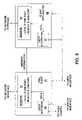
- FIG. 7is a block diagram showing the elements of the computer hosting the shared resources in greater detail.
- FIG. 8is a block diagram showing the elements of the remote computer accessing the shared resources in greater detail.
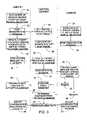
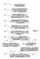
- FIG. 9is a flowchart showing preferred embodiments for establishing the private sharing of computer resources between network users.
- a plurality of user computers 10 , 11 , and 12 , and a central server 13are internetworked via the Internet 14 .
- a plurality of routers 15 within Internet 14direct packets between various endpoints or nodes.
- Computers 10 and 11are shown as being connected to Internet routers belonging to Internet Service Providers (ISP's) 16 and 17 , respectively.
- ISP'sInternet Service Providers
- the connections to the ISP'smay be by dial-up, digital subscriber line (DSL), cable modem, or integrated access device (IAD), for example.
- Central server 13 and computer 12are shown directly connected to a router.
- Network communicationcomprises data messages or packets transferred between separate endpoints, such as between computers 10 , 11 , or 12 (as clients) and central server 13 .
- the packet transferis accomplished by routers 15 using the IP addresses contained in each packet.
- Central server 13typically has a fixed IP address that is listed on the DNS servers accessible to each computer. Each computer user can easily communicate with central server 13 by supplying its logical name (e.g., www.sprint.exchange.com) which is automatically resolved by their browser into an IP address by consulting a DNS server. Exchanging packets between users 10 , 11 , and 12 themselves cannot usually be accomplished in the same way because the users and their IP addresses are not listed in the DNS system. Furthermore, users 10 , 11 , and 12 may not wish to allow remote access into their computers except in certain circumstances.
- the present inventionfacilitates exchanging data messages between two individual users by providing a specialized directory or look-up within central sever 13 .
- the present inventionmay be used within a system that functions to simultaneously establish a voice telephone call between the two individual computer users.
- the voice callserves as the user action that initiates the computer processing to establish the computer-to-computer connection.
- the voice callprovides a way to alert the called party of the request to establish the computer connection and then serves to enhance the interaction between the two users during the exchange of computer data.
- the present inventionalso provides other methods for initiating the computer processing, and a simultaneous voice telephone call is not necessary in the present invention.
- computers 10 and 11have associated telephones 18 and 19 used by the same respective users.
- the computers and telephonesmay be fixed installations (e.g., in a residence or a business office) or may be mobile devices (e.g., laptop computer and cellular phone), as long as both are accessible to each user at the same time.
- the telephonesare connected to the public switched telephone network (PSTN) 20 .
- Central server 13provides a user look-up and interconnecting service for registered users. For security and/or billing purposes, access to the service preferably is tied to user ID's and passwords. A user may be given an ID and password with initial sign-up for the service. Each user would manually configure the telephone number that they want to be associated with.
- central server 13When the user is “on-line” (i.e., has their computer turned on and connected to Internet 14 ), their computer sends a registration message to central server 13 to notify it that the user is available. Central server 13 can inspect the registration message to determine the current IP address and port number at which the user resides for its current connection session. Alternatively, the user may manually configure their IP address in some circumstances. Upon registration, central server 13 may preferably determine whether the user has a respective firewall as described in copending U.S. application Ser. No. 10/034,012. In any case, central server 13 contains a database of currently active, registered users. Each user entry in the database includes fields for user ID, password, telephone number, and IP address (including port number), user status, and a firewall flag, for example.
- a user # 1dials telephone 18 to make a voice call to a user # 2 at telephone 19 .
- the telephone number dialed by user # 1is captured as a target telephone identifier number and sent to a call client (i.e., an application program for managing the data call) in computer 10 being used by user # 1 .
- Computer 10forwards the target telephone number to central server 13 as part of an access request for establishing a connection with user # 2 .
- Central server 13looks up the target number in its database. When it finds the target number, central server 13 identifies the IP address associated with user # 2 and sends an initiation message to computer 11 being used by user # 2 .
- computer 11receives the initiation message, it launches its own call client.
- the initiation messagemay identify user # 1 (preferably by both telephone number and user ID) and the type of data to be exchanged (i.e., the application program or how the call client should be configured to receive the data).
- User # 2answers the telephone voice call and learns that an initiation message was sent to their computer. Using computer 11 , user # 2 can verify the calling party as user # 1 and can indicate whether they accept the computer network connection (i.e., the data call) with user # 1 .
- data messagescan be exchanged between the call client application programs running on computers 10 and 11 .
- the call client application programscan be written to perform file transfers of various types of files, video data or frames for video telephony, or other real-time data or control signals. It may also be desired by a user to share computer data or other computer resources besides the data or file types that have been programmed into the call clients, as described below.
- step 21user # 1 invokes the real-time interconnection service of the present invention. This can be configured as part of the normal start-up of their computer or can result from manually launching a software application such as the call client after start-up has finished.
- a registration messageis sent to the central server in step 22 .
- the registration messagepreferably includes the user ID and password assigned to user # 1 .
- the application software that creates the registration messagemay also determine the local IP address being used by the computer and includes this as data within the registration message.
- the registration messagewould typically also include the telephone number being used by user # 1 .
- the IP address (and port number)is typically embedded in each packet forwarded by the network and the central server preferably extracts the automatically embedded IP address and port number.
- the central serverreceives the registration message and adds the new user to the database or updates the user status, as necessary.
- user # 2invokes the real-time interconnection service in step 24 .
- User # 2sends a registration message in step 25 , and the central server receives the registration message and adds user # 2 to the database or updates the user status, as necessary. Thereafter, the central server may periodically exchange further messages with each registered user to keep the user status current and to maintain an open session with each user, for example.
- an unregister message(not shown) may also be sent to the central server.
- user # 1desires to exchange computer data with user # 2 .
- user # 1initiates an attempt to contact user # 2 and set up the data exchange.
- user # 1may identify user # 2 by virtue of user # 2 's telephone number.
- This target telephone numbermay preferably be captured from the act of dialing it on user # 1 's telephone equipment.
- a dedicated modulemay be connected to user # 1 's telephone to detect the DTMF tones while dialing and to send the dialed number to user # 1 's computer.
- the target telephone number for user # 2is included in an access request message sent to the central server in step 28 .
- step 30the central server looks up the target telephone number and gets the IP address (and port number) associated with user # 2 .
- the initiation messageis sent by the central server in step 31 .
- User # 2receives the initiation message in step 32 . If not already running, the user # 2 computer launches the appropriate call client application for responding to the initiation message and then prompts user # 2 to either accept or reject the access request. If rejected, then user # 2 generates a reject message in step 33 and sends it to the central server. In step 34 , the central server forwards the reject message to user # 1 , which then terminates the data portion of the attempted communication session in step 35 (the voice telephone call is accepted, rejected, or terminated separately).
- step 36the central server determines any needed configurations for accomplishing the data exchange and then configures the user # 1 and user # 2 endpoints in step 38 .
- the two main configurations for the data exchangewill be described in connection with FIGS. 4 and 5 and are selected on the basis of detected firewalls, for example.
- the user # 1 and user # 2 computersaccept the configuration and then begin to exchange the data messages or packets in step 39 .
- Other configuration issuessuch as the configuration of the client application programs exchanging the actual data messages can be handled within the access request message, the initiation message, the accept message, and/or other packets exchanged between the endpoints, for example.
- a first packet exchange configurationis shown in FIG. 4 wherein central server 13 performs a relay function such that all packets exchanged between computer 10 and computer 11 pass through central server 13 .
- central server 13performs a relay function such that all packets exchanged between computer 10 and computer 11 pass through central server 13 .
- both endpointscontinue to address their sent packets to central server 13 .
- each packetis redirected by substitution of IP addresses. For example, a packet sent from computer 10 including its own IP address as the source address of the packet and the IP address of central server 13 as the destination address of the packet is modified after being received by central server 13 to have the central server's address as its source address and to have the IP address of computer 11 as its destination address.
- central server 13After modification, central server 13 sends the packet back to its router and on to computer 11 . The same operations are used to send packets from computer 11 to computer 10 .
- the embodiment of FIG. 4has the advantage that greater privacy of a user's IP address is maintained since each user's computer only needs to see the IP address of central server 13 . Furthermore, this configuration can readily function in the presence of network address translation (NAT) firewalls at the endpoints.
- NATnetwork address translation
- FIG. 5shows an alternative configuration in which direct packet exchange between computers 10 and 11 is realized.
- Central server 13provides a look-up function and a connection initiation function. If desired user # 2 (called party) accepts a data call, then central server 13 provides the IP address of computer 11 to computer 10 and provides the IP address of computer 10 to computer 11 . Thereafter, each computer can send packets addressed to the other computer and the packets are no longer relayed through central server 13 .
- This embodimenthas the advantage that central server 13 may be reduced in size since less traffic flows through it.
- connection method of FIG. 4 or FIG. 5is transparent to the users. Once either type of data call is established and the call clients are exchanging data messages over the internetwork, the sharing of computer resources is expanded beyond the functionality of the call clients as shown in FIG. 6 .
- Computer 10includes a network interface 40 and a call client 41 performing the functions already described.
- Computer 10runs a server application 42 for hosting a shared resource 43 such as a particular audio or video media, html pages, or a database, for example.
- computer 10runs a client application 44 which is designed to access or otherwise interact with or display shared resource 43 .
- a user interface 45may, for example, include operating system software and input/output devices (e.g. monitor, mouse, and keyboard) by which a user interacts with (e.g., provides user commands to) call client 41 , server application 42 , and client application 44 .
- computer 11includes a network interface 50 , a call client 51 , a client application 52 , and a user interface 53 for remotely accessing shared resource 43 via Internet 14 .
- FIG. 7shows the operation of computer 10 for serving the shared resource between both computers in greater detail.
- call client 41creates a network session 46 between itself (as referenced within computer 10 by the local IP address of computer 10 and the port address used by call client 41 ) and, depending upon the connection mode, either central server 13 or remote computer 11 (as referenced within computer 10 by a remote IP address and port address which were provided by central server 13 ).
- central server 13 or remote computer 11as referenced within computer 10 by a remote IP address and port address which were provided by central server 13 .
- datais exchanged between computers 10 and 11 .
- the one-way or two-way video datais passed between session 46 and video software 47 .
- Video software 47processes video from a video camera and forwards it to session 46 .
- Video software 47also processes remote video data received from session 46 and feeds it to a display interface within the overall user interface.
- a user commandis generated within the user interface to request the sharing of computer resources other than that within the functionality of call client 41 (e.g., a user mouse clicks a program launcher for the desired resource).
- Server application 42 and client application 44are launched if not already active.
- One example of a resource shared in this manneris streaming of compressed, prerecorded video as described in copending U.S. application Ser. No. 10/058,882.
- Client application 44uses the data or other shared resource in the manner desired by the user, and server application 42 serves the shared data or other resource simultaneously to the local user and one or more remote users.
- server application 42creates a remote session 48 for exchanging network packets with the remote user (e.g., via central server 13 ) and a local session 49 for communicating with client application 44 .
- Local session 49utilizes the local port numbers of the two applications for communicating the data or other resource between served resource 43 and client application 44 .
- Remote session 48obtains remote session address and port information from session 46 in call client 41 .
- server application 42may issue a request via the operating system/user interface to call client 41 for the IP address and port address for the remote call client in the remote computer. Call client reports this session information to server application 42 which then establishes its remote session 48 in one of two ways.
- a separate network sessionis created by sending an initiation message to remote computer 11 .
- server application 42provides its distinct port address rather than the port address of call client 41 .
- call client 41 and server application 42can communicate with the remote user in parallel.
- call client 41either terminates or goes into hibernation and server application 42 takes over the existing network session. In other words, server application 42 assumes the port address used by call client 41 in the existing session and no new initiation message is sent.
- FIG. 8shows remote computer 11 where the shared resource does not reside.
- client application 52is launched if not already running.
- a session 56obtains remote IP address and port address information of computer 10 and creates or accepts a network session as described above.
- Data utilization software 57exchanges data with the remote server application via session 56 .
- step 60multiple users sign-on or register with the central server.
- a calling userlaunches their call client on their computer in step 61 .
- the calling usermakes a telephone call to the called user, and the act of dialing the telephone number may send a signal to the computer for automatically launching the call client if it is not already running.
- no telephone callis necessary and the calling user may enter a telephone number or other identifying information of the called user into the call client.
- step 62the phone number or other identifying information is sent to the central server and a data call is established with the called user.
- step 63either user initiates a request via their user interface for sharing of resources not accessible to the call clients. If the request is initiated by the user that is remote from the shared resources, then their call client forwards the request.
- the server applicationis launched on the computer where the shared resources reside in step 64 .
- both computerslaunch appropriate client applications for accessing the served data from the server application, such as a media player or a browser.
- one or both call clientsreport IP addresses and port addresses of the other computers to the server application and/or the client application(s). For example, the remote IP address used in the call client of the computer where the shared resource resides is reported to the server application. Also, the remote IP address used in the call client of the computer not containing the shared resource is reported to the client application running in that computer.
- the network session between the server application and the client application of the remote computerfollows either one of two methods as shown in FIG. 9 .
- a second session between the two computersis created by means of either the server application or the remote client application sending a session initiation message to the other using the existing IP address information but using a new port address for the origination application.
- a new port address for the other applicationcan be identified in a response to the session initiation message.
- both call clientseither terminate or hibernate in step 68 .
- the server application and the remote client applicationuse the existing session's IP addresses and ports.
- both client applicationsinteract with the server application in order to access the shared resource simultaneously.
- the present inventionhas been described with respect to two users sharing a particular resource, the invention also contemplates that three or more users could simultaneously share a resource or participate in a video telephony call. In that case, the server application would multicast to each of the remote computers, for example.
Landscapes
- Engineering & Computer Science (AREA)
- Signal Processing (AREA)
- Computer Networks & Wireless Communication (AREA)
- Multimedia (AREA)
- Data Exchanges In Wide-Area Networks (AREA)
- Telephonic Communication Services (AREA)
Abstract
Description
Claims (16)
Priority Applications (2)
| Application Number | Priority Date | Filing Date | Title |
|---|---|---|---|
| US10/058,549US7385621B2 (en) | 2001-10-16 | 2002-01-28 | Private sharing of computer resources over an internetwork |
| PCT/US2002/031947WO2003034692A2 (en) | 2001-10-16 | 2002-10-04 | Telephonic addressing for establishing simultaneous voice and computer network connections |
Applications Claiming Priority (3)
| Application Number | Priority Date | Filing Date | Title |
|---|---|---|---|
| US09/978,616US6545697B1 (en) | 2001-10-16 | 2001-10-16 | Video telephony |
| US10/033,813US7099288B1 (en) | 2001-10-16 | 2001-12-20 | Telephonic addressing for establishing simultaneous voice and computer network connections |
| US10/058,549US7385621B2 (en) | 2001-10-16 | 2002-01-28 | Private sharing of computer resources over an internetwork |
Related Parent Applications (2)
| Application Number | Title | Priority Date | Filing Date |
|---|---|---|---|
| US10/033,813Continuation-In-PartUS7099288B1 (en) | 2001-10-16 | 2001-12-20 | Telephonic addressing for establishing simultaneous voice and computer network connections |
| US3381302AContinuation-In-Part | 2001-10-16 | 2002-01-03 |
Publications (2)
| Publication Number | Publication Date |
|---|---|
| US20040246950A1 US20040246950A1 (en) | 2004-12-09 |
| US7385621B2true US7385621B2 (en) | 2008-06-10 |
Family
ID=46298783
Family Applications (1)
| Application Number | Title | Priority Date | Filing Date |
|---|---|---|---|
| US10/058,549Expired - LifetimeUS7385621B2 (en) | 2001-10-16 | 2002-01-28 | Private sharing of computer resources over an internetwork |
Country Status (1)
| Country | Link |
|---|---|
| US (1) | US7385621B2 (en) |
Cited By (2)
| Publication number | Priority date | Publication date | Assignee | Title |
|---|---|---|---|---|
| US20060242242A1 (en)* | 2003-01-27 | 2006-10-26 | Canon Kabushiki Kaisha | Communication terminal, communication terminal control method, and communication terminal control program |
| US7787611B1 (en)* | 2004-09-17 | 2010-08-31 | Cisco Technology, Inc. | Packet telephony bridging server |
Families Citing this family (19)
| Publication number | Priority date | Publication date | Assignee | Title |
|---|---|---|---|---|
| JP3870882B2 (en)* | 2002-09-12 | 2007-01-24 | ソニー株式会社 | Information communication system, information communication apparatus, information communication method, and computer program |
| WO2005086802A2 (en) | 2004-03-08 | 2005-09-22 | Proxense, Llc | Linked account system using personal digital key (pdk-las) |
| EP1829283A2 (en) | 2004-12-20 | 2007-09-05 | Proxense, LLC | Biometric personal data key (pdk) authentication |
| JP2008529184A (en)* | 2005-02-04 | 2008-07-31 | コーニンクレッカ フィリップス エレクトロニクス エヌ ヴィ | Method, apparatus, system and token for creating an authorization domain |
| US11206664B2 (en) | 2006-01-06 | 2021-12-21 | Proxense, Llc | Wireless network synchronization of cells and client devices on a network |
| US8219129B2 (en) | 2006-01-06 | 2012-07-10 | Proxense, Llc | Dynamic real-time tiered client access |
| US7904718B2 (en) | 2006-05-05 | 2011-03-08 | Proxense, Llc | Personal digital key differentiation for secure transactions |
| US9269221B2 (en) | 2006-11-13 | 2016-02-23 | John J. Gobbi | Configuration of interfaces for a location detection system and application |
| US8659427B2 (en) | 2007-11-09 | 2014-02-25 | Proxense, Llc | Proximity-sensor supporting multiple application services |
| US8171528B1 (en) | 2007-12-06 | 2012-05-01 | Proxense, Llc | Hybrid device having a personal digital key and receiver-decoder circuit and methods of use |
| US9251332B2 (en) | 2007-12-19 | 2016-02-02 | Proxense, Llc | Security system and method for controlling access to computing resources |
| WO2009102979A2 (en) | 2008-02-14 | 2009-08-20 | Proxense, Llc | Proximity-based healthcare management system with automatic access to private information |
| WO2009126732A2 (en) | 2008-04-08 | 2009-10-15 | Proxense, Llc | Automated service-based order processing |
| US9418205B2 (en) | 2010-03-15 | 2016-08-16 | Proxense, Llc | Proximity-based system for automatic application or data access and item tracking |
| US8918854B1 (en) | 2010-07-15 | 2014-12-23 | Proxense, Llc | Proximity-based system for automatic application initialization |
| US8857716B1 (en) | 2011-02-21 | 2014-10-14 | Proxense, Llc | Implementation of a proximity-based system for object tracking and automatic application initialization |
| WO2014183106A2 (en) | 2013-05-10 | 2014-11-13 | Proxense, Llc | Secure element as a digital pocket |
| KR102118002B1 (en)* | 2013-07-26 | 2020-06-02 | 삼성전자주식회사 | Method for communication using ip address eschanged via near field communication and apparatus for the same |
| US11423377B1 (en)* | 2013-08-26 | 2022-08-23 | Amazon Technologies, Inc. | Lendable computing resources |
Citations (14)
| Publication number | Priority date | Publication date | Assignee | Title |
|---|---|---|---|---|
| EP0721266A2 (en) | 1995-01-09 | 1996-07-10 | NCR International, Inc. | Collaborative computer system |
| US5689553A (en) | 1993-04-22 | 1997-11-18 | At&T Corp. | Multimedia telecommunications network and service |
| US5764916A (en) | 1996-09-27 | 1998-06-09 | Ichat, Inc. | Method and apparatus for real time communication over a computer network |
| US5949763A (en) | 1997-07-17 | 1999-09-07 | Ameritech Corporation | Method and apparatus for providing broadband access conferencing services |
| EP0999712A2 (en) | 1998-11-06 | 2000-05-10 | Nortel Networks Corporation | Multimedia channel management through PSTN signalling |
| US6097793A (en) | 1998-06-22 | 2000-08-01 | Telefonaktiebolaget Lm Ericsson | WWW-telephony integration |
| US6122259A (en)* | 1996-02-27 | 2000-09-19 | Hitachi, Ltd. | Video conference equipment and multipoint video conference system using the same |
| EP1059798A2 (en) | 1999-06-07 | 2000-12-13 | AT&T Corp. | Voice-over-IP enabled chat |
| GB2357659A (en) | 1999-12-23 | 2001-06-27 | Mitel Corp | Communication system architecture for voice first collaboration |
| WO2001071994A1 (en) | 2000-03-20 | 2001-09-27 | Interconware, Inc. | Method and system for telephone communication |
| US6337858B1 (en) | 1997-10-10 | 2002-01-08 | Nortel Networks Limited | Method and apparatus for originating voice calls from a data network |
| US6463460B1 (en)* | 1999-04-23 | 2002-10-08 | The United States Of America As Represented By The Secretary Of The Navy | Interactive communication system permitting increased collaboration between users |
| US6539077B1 (en) | 1998-06-05 | 2003-03-25 | Netnumber.Com, Inc. | Method and apparatus for correlating a unique identifier, such as a PSTN telephone number, to an internet address to enable communications over the internet |
| US6704294B1 (en)* | 1999-10-13 | 2004-03-09 | Nortel Networks Limited | Establishment of a PSTN and internet multimedia collaboration session |
- 2002
- 2002-01-28USUS10/058,549patent/US7385621B2/ennot_activeExpired - Lifetime
Patent Citations (15)
| Publication number | Priority date | Publication date | Assignee | Title |
|---|---|---|---|---|
| US5689553A (en) | 1993-04-22 | 1997-11-18 | At&T Corp. | Multimedia telecommunications network and service |
| EP0721266A2 (en) | 1995-01-09 | 1996-07-10 | NCR International, Inc. | Collaborative computer system |
| US6122259A (en)* | 1996-02-27 | 2000-09-19 | Hitachi, Ltd. | Video conference equipment and multipoint video conference system using the same |
| US5764916A (en) | 1996-09-27 | 1998-06-09 | Ichat, Inc. | Method and apparatus for real time communication over a computer network |
| US5949763A (en) | 1997-07-17 | 1999-09-07 | Ameritech Corporation | Method and apparatus for providing broadband access conferencing services |
| US6370137B1 (en) | 1997-07-17 | 2002-04-09 | Ameritech Corporation | Method and apparatus for providing broadband access conferencing services |
| US6337858B1 (en) | 1997-10-10 | 2002-01-08 | Nortel Networks Limited | Method and apparatus for originating voice calls from a data network |
| US6539077B1 (en) | 1998-06-05 | 2003-03-25 | Netnumber.Com, Inc. | Method and apparatus for correlating a unique identifier, such as a PSTN telephone number, to an internet address to enable communications over the internet |
| US6097793A (en) | 1998-06-22 | 2000-08-01 | Telefonaktiebolaget Lm Ericsson | WWW-telephony integration |
| EP0999712A2 (en) | 1998-11-06 | 2000-05-10 | Nortel Networks Corporation | Multimedia channel management through PSTN signalling |
| US6463460B1 (en)* | 1999-04-23 | 2002-10-08 | The United States Of America As Represented By The Secretary Of The Navy | Interactive communication system permitting increased collaboration between users |
| EP1059798A2 (en) | 1999-06-07 | 2000-12-13 | AT&T Corp. | Voice-over-IP enabled chat |
| US6704294B1 (en)* | 1999-10-13 | 2004-03-09 | Nortel Networks Limited | Establishment of a PSTN and internet multimedia collaboration session |
| GB2357659A (en) | 1999-12-23 | 2001-06-27 | Mitel Corp | Communication system architecture for voice first collaboration |
| WO2001071994A1 (en) | 2000-03-20 | 2001-09-27 | Interconware, Inc. | Method and system for telephone communication |
Cited By (3)
| Publication number | Priority date | Publication date | Assignee | Title |
|---|---|---|---|---|
| US20060242242A1 (en)* | 2003-01-27 | 2006-10-26 | Canon Kabushiki Kaisha | Communication terminal, communication terminal control method, and communication terminal control program |
| US8306196B2 (en)* | 2003-01-27 | 2012-11-06 | Canon Kabushiki Kaisha | Communication terminal, control method for communication terminal and control program for communication terminal |
| US7787611B1 (en)* | 2004-09-17 | 2010-08-31 | Cisco Technology, Inc. | Packet telephony bridging server |
Also Published As
| Publication number | Publication date |
|---|---|
| US20040246950A1 (en) | 2004-12-09 |
Similar Documents
| Publication | Publication Date | Title |
|---|---|---|
| US7046269B2 (en) | Sharing of prerecorded motion video over an internetwork | |
| US7058689B2 (en) | Sharing of still images within a video telephony call | |
| US7385621B2 (en) | Private sharing of computer resources over an internetwork | |
| US6677976B2 (en) | Integration of video telephony with chat and instant messaging environments | |
| US7099288B1 (en) | Telephonic addressing for establishing simultaneous voice and computer network connections | |
| US8027335B2 (en) | Multimedia access device and system employing the same | |
| US7573873B1 (en) | Internet telephony using network address translation | |
| US6192044B1 (en) | Employing a look-up service and a callee connection service to establish a network phone call between a caller and a callee | |
| CA2269926C (en) | Distributed call system | |
| US20040243710A1 (en) | Method of user data exchange in the data network and a data network | |
| US20070217408A1 (en) | Address Resolution Device, Address Resolution Method, And Communication System Including The Same | |
| JPH1093629A (en) | Intelligent processing for building communications on the Internet | |
| WO2003030463A1 (en) | A method and system for realizing ip voice service at private network | |
| US7457254B2 (en) | Method and system for automatic language negotiation on voice (over IP) calls | |
| US7542475B2 (en) | Communication between users located behind a NAT device | |
| CN112953925A (en) | Real-time audio and video communication system and method based on SIP (Session initiation protocol) and RTC (real time communication) network | |
| US20070233901A1 (en) | Methods and systems for integrating network services with multiple communication protocols | |
| WO2004032471A1 (en) | Multimedia pickup service | |
| US7756257B2 (en) | SIP enabled device identification | |
| WO2012071917A1 (en) | Method for voip instant call | |
| KR20010057377A (en) | VPN service provisioning method using session agent | |
| US20020191769A1 (en) | Connection-selection method and telecommunication endpoint device | |
| JP2002009846A (en) | Communication system using multimedia proxy server | |
| JP4728933B2 (en) | IP telephone communication system, IP telephone communication method, and program thereof | |
| US7769865B1 (en) | Configuring computer network communications in response to detected firewalls |
Legal Events
| Date | Code | Title | Description |
|---|---|---|---|
| AS | Assignment | Owner name:SPRINT COMMUNICATIONS COMPANY, LTD., MISSOURI Free format text:ASSIGNMENT OF ASSIGNORS INTEREST;ASSIGNORS:PARKER, BENJAMIN J.;WERNER, SHANE R.;DIAZ, CHARLES;AND OTHERS;REEL/FRAME:012547/0708;SIGNING DATES FROM 20020122 TO 20020124 | |
| STCF | Information on status: patent grant | Free format text:PATENTED CASE | |
| FPAY | Fee payment | Year of fee payment:4 | |
| FPAY | Fee payment | Year of fee payment:8 | |
| AS | Assignment | Owner name:DEUTSCHE BANK TRUST COMPANY AMERICAS, NEW YORK Free format text:GRANT OF FIRST PRIORITY AND JUNIOR PRIORITY SECURITY INTEREST IN PATENT RIGHTS;ASSIGNOR:SPRINT COMMUNICATIONS COMPANY L.P.;REEL/FRAME:041895/0210 Effective date:20170203 | |
| MAFP | Maintenance fee payment | Free format text:PAYMENT OF MAINTENANCE FEE, 12TH YEAR, LARGE ENTITY (ORIGINAL EVENT CODE: M1553); ENTITY STATUS OF PATENT OWNER: LARGE ENTITY Year of fee payment:12 | |
| AS | Assignment | Owner name:SPRINT COMMUNICATIONS COMPANY L.P., KANSAS Free format text:TERMINATION AND RELEASE OF FIRST PRIORITY AND JUNIOR PRIORITY SECURITY INTEREST IN PATENT RIGHTS;ASSIGNOR:DEUTSCHE BANK TRUST COMPANY AMERICAS;REEL/FRAME:052969/0475 Effective date:20200401 Owner name:DEUTSCHE BANK TRUST COMPANY AMERICAS, NEW YORK Free format text:SECURITY AGREEMENT;ASSIGNORS:T-MOBILE USA, INC.;ISBV LLC;T-MOBILE CENTRAL LLC;AND OTHERS;REEL/FRAME:053182/0001 Effective date:20200401 | |
| AS | Assignment | Owner name:T-MOBILE INNOVATIONS LLC, KANSAS Free format text:ASSIGNMENT OF ASSIGNORS INTEREST;ASSIGNOR:SPRINT COMMUNICATIONS COMPANY L.P.;REEL/FRAME:055604/0001 Effective date:20210303 | |
| AS | Assignment | Owner name:SPRINT SPECTRUM LLC, KANSAS Free format text:RELEASE BY SECURED PARTY;ASSIGNOR:DEUTSCHE BANK TRUST COMPANY AMERICAS;REEL/FRAME:062595/0001 Effective date:20220822 Owner name:SPRINT INTERNATIONAL INCORPORATED, KANSAS Free format text:RELEASE BY SECURED PARTY;ASSIGNOR:DEUTSCHE BANK TRUST COMPANY AMERICAS;REEL/FRAME:062595/0001 Effective date:20220822 Owner name:SPRINT COMMUNICATIONS COMPANY L.P., KANSAS Free format text:RELEASE BY SECURED PARTY;ASSIGNOR:DEUTSCHE BANK TRUST COMPANY AMERICAS;REEL/FRAME:062595/0001 Effective date:20220822 Owner name:SPRINTCOM LLC, KANSAS Free format text:RELEASE BY SECURED PARTY;ASSIGNOR:DEUTSCHE BANK TRUST COMPANY AMERICAS;REEL/FRAME:062595/0001 Effective date:20220822 Owner name:CLEARWIRE IP HOLDINGS LLC, KANSAS Free format text:RELEASE BY SECURED PARTY;ASSIGNOR:DEUTSCHE BANK TRUST COMPANY AMERICAS;REEL/FRAME:062595/0001 Effective date:20220822 Owner name:CLEARWIRE COMMUNICATIONS LLC, KANSAS Free format text:RELEASE BY SECURED PARTY;ASSIGNOR:DEUTSCHE BANK TRUST COMPANY AMERICAS;REEL/FRAME:062595/0001 Effective date:20220822 Owner name:BOOST WORLDWIDE, LLC, KANSAS Free format text:RELEASE BY SECURED PARTY;ASSIGNOR:DEUTSCHE BANK TRUST COMPANY AMERICAS;REEL/FRAME:062595/0001 Effective date:20220822 Owner name:ASSURANCE WIRELESS USA, L.P., KANSAS Free format text:RELEASE BY SECURED PARTY;ASSIGNOR:DEUTSCHE BANK TRUST COMPANY AMERICAS;REEL/FRAME:062595/0001 Effective date:20220822 Owner name:T-MOBILE USA, INC., WASHINGTON Free format text:RELEASE BY SECURED PARTY;ASSIGNOR:DEUTSCHE BANK TRUST COMPANY AMERICAS;REEL/FRAME:062595/0001 Effective date:20220822 Owner name:T-MOBILE CENTRAL LLC, WASHINGTON Free format text:RELEASE BY SECURED PARTY;ASSIGNOR:DEUTSCHE BANK TRUST COMPANY AMERICAS;REEL/FRAME:062595/0001 Effective date:20220822 Owner name:PUSHSPRING, LLC, WASHINGTON Free format text:RELEASE BY SECURED PARTY;ASSIGNOR:DEUTSCHE BANK TRUST COMPANY AMERICAS;REEL/FRAME:062595/0001 Effective date:20220822 Owner name:LAYER3 TV, LLC, WASHINGTON Free format text:RELEASE BY SECURED PARTY;ASSIGNOR:DEUTSCHE BANK TRUST COMPANY AMERICAS;REEL/FRAME:062595/0001 Effective date:20220822 Owner name:IBSV LLC, WASHINGTON Free format text:RELEASE BY SECURED PARTY;ASSIGNOR:DEUTSCHE BANK TRUST COMPANY AMERICAS;REEL/FRAME:062595/0001 Effective date:20220822 |