US7384308B2 - Detachable coupling for a remote inspection device - Google Patents
Detachable coupling for a remote inspection deviceDownload PDFInfo
- Publication number
- US7384308B2 US7384308B2US11/645,276US64527606AUS7384308B2US 7384308 B2US7384308 B2US 7384308B2US 64527606 AUS64527606 AUS 64527606AUS 7384308 B2US7384308 B2US 7384308B2
- Authority
- US
- United States
- Prior art keywords
- cable
- casing
- ferrule
- ferrule component
- component
- Prior art date
- Legal status (The legal status is an assumption and is not a legal conclusion. Google has not performed a legal analysis and makes no representation as to the accuracy of the status listed.)
- Active
Links
- 230000008878couplingEffects0.000titleclaimsabstractdescription100
- 238000010168coupling processMethods0.000titleclaimsabstractdescription100
- 238000005859coupling reactionMethods0.000titleclaimsabstractdescription100
- 238000007689inspectionMethods0.000titleclaimsabstractdescription52
- 238000003384imaging methodMethods0.000claimsabstractdescription33
- 230000000295complement effectEffects0.000claimsdescription18
- 239000011810insulating materialSubstances0.000claimsdescription15
- 238000004891communicationMethods0.000claimsdescription13
- 239000012530fluidSubstances0.000claimsdescription12
- 239000000615nonconductorSubstances0.000claimsdescription9
- 238000007789sealingMethods0.000claimsdescription8
- 230000000712assemblyEffects0.000claimsdescription5
- 238000000429assemblyMethods0.000claimsdescription5
- 239000012777electrically insulating materialSubstances0.000claimsdescription4
- 239000000463materialSubstances0.000description8
- 238000000034methodMethods0.000description6
- 230000007246mechanismEffects0.000description4
- 239000004033plasticSubstances0.000description3
- 239000004677NylonSubstances0.000description2
- NIXOWILDQLNWCW-UHFFFAOYSA-Nacrylic acid groupChemical groupC(C=C)(=O)ONIXOWILDQLNWCW-UHFFFAOYSA-N0.000description2
- 238000010276constructionMethods0.000description2
- 238000010586diagramMethods0.000description2
- 239000002184metalSubstances0.000description2
- 210000002445nippleAnatomy0.000description2
- 229920001778nylonPolymers0.000description2
- 239000004593EpoxySubstances0.000description1
- 239000000853adhesiveSubstances0.000description1
- 230000001070adhesive effectEffects0.000description1
- 230000008901benefitEffects0.000description1
- 239000002131composite materialSubstances0.000description1
- 230000000694effectsEffects0.000description1
- 235000015168fish fingersNutrition0.000description1
- 239000006260foamSubstances0.000description1
- 239000003292glueSubstances0.000description1
- 230000005484gravityEffects0.000description1
- 238000005286illuminationMethods0.000description1
- 230000002452interceptive effectEffects0.000description1
- 239000004973liquid crystal related substanceSubstances0.000description1
- 238000004519manufacturing processMethods0.000description1
- 230000013011matingEffects0.000description1
- 239000011159matrix materialSubstances0.000description1
- 238000009428plumbingMethods0.000description1
- 230000008569processEffects0.000description1
- 230000001681protective effectEffects0.000description1
- 239000012780transparent materialSubstances0.000description1
- 238000004078waterproofingMethods0.000description1
Images


Classifications
- G—PHYSICS
- G02—OPTICS
- G02B—OPTICAL ELEMENTS, SYSTEMS OR APPARATUS
- G02B23/00—Telescopes, e.g. binoculars; Periscopes; Instruments for viewing the inside of hollow bodies; Viewfinders; Optical aiming or sighting devices
- G02B23/24—Instruments or systems for viewing the inside of hollow bodies, e.g. fibrescopes
- G02B23/2476—Non-optical details, e.g. housings, mountings, supports
- A—HUMAN NECESSITIES
- A61—MEDICAL OR VETERINARY SCIENCE; HYGIENE
- A61B—DIAGNOSIS; SURGERY; IDENTIFICATION
- A61B1/00—Instruments for performing medical examinations of the interior of cavities or tubes of the body by visual or photographical inspection, e.g. endoscopes; Illuminating arrangements therefor
- A61B1/00002—Operational features of endoscopes
- A61B1/00043—Operational features of endoscopes provided with output arrangements
- A61B1/00045—Display arrangement
- A61B1/00052—Display arrangement positioned at proximal end of the endoscope body
- A—HUMAN NECESSITIES
- A61—MEDICAL OR VETERINARY SCIENCE; HYGIENE
- A61B—DIAGNOSIS; SURGERY; IDENTIFICATION
- A61B1/00—Instruments for performing medical examinations of the interior of cavities or tubes of the body by visual or photographical inspection, e.g. endoscopes; Illuminating arrangements therefor
- A61B1/00064—Constructional details of the endoscope body
- A61B1/00071—Insertion part of the endoscope body
- A61B1/0008—Insertion part of the endoscope body characterised by distal tip features
- A61B1/00087—Tools
- A—HUMAN NECESSITIES
- A61—MEDICAL OR VETERINARY SCIENCE; HYGIENE
- A61B—DIAGNOSIS; SURGERY; IDENTIFICATION
- A61B1/00—Instruments for performing medical examinations of the interior of cavities or tubes of the body by visual or photographical inspection, e.g. endoscopes; Illuminating arrangements therefor
- A61B1/005—Flexible endoscopes
- A61B1/0051—Flexible endoscopes with controlled bending of insertion part
- A—HUMAN NECESSITIES
- A61—MEDICAL OR VETERINARY SCIENCE; HYGIENE
- A61B—DIAGNOSIS; SURGERY; IDENTIFICATION
- A61B1/00—Instruments for performing medical examinations of the interior of cavities or tubes of the body by visual or photographical inspection, e.g. endoscopes; Illuminating arrangements therefor
- A61B1/04—Instruments for performing medical examinations of the interior of cavities or tubes of the body by visual or photographical inspection, e.g. endoscopes; Illuminating arrangements therefor combined with photographic or television appliances
- A61B1/05—Instruments for performing medical examinations of the interior of cavities or tubes of the body by visual or photographical inspection, e.g. endoscopes; Illuminating arrangements therefor combined with photographic or television appliances characterised by the image sensor, e.g. camera, being in the distal end portion
- A—HUMAN NECESSITIES
- A61—MEDICAL OR VETERINARY SCIENCE; HYGIENE
- A61B—DIAGNOSIS; SURGERY; IDENTIFICATION
- A61B1/00—Instruments for performing medical examinations of the interior of cavities or tubes of the body by visual or photographical inspection, e.g. endoscopes; Illuminating arrangements therefor
- A61B1/06—Instruments for performing medical examinations of the interior of cavities or tubes of the body by visual or photographical inspection, e.g. endoscopes; Illuminating arrangements therefor with illuminating arrangements
- A61B1/0607—Instruments for performing medical examinations of the interior of cavities or tubes of the body by visual or photographical inspection, e.g. endoscopes; Illuminating arrangements therefor with illuminating arrangements for annular illumination
- A—HUMAN NECESSITIES
- A61—MEDICAL OR VETERINARY SCIENCE; HYGIENE
- A61B—DIAGNOSIS; SURGERY; IDENTIFICATION
- A61B1/00—Instruments for performing medical examinations of the interior of cavities or tubes of the body by visual or photographical inspection, e.g. endoscopes; Illuminating arrangements therefor
- A61B1/06—Instruments for performing medical examinations of the interior of cavities or tubes of the body by visual or photographical inspection, e.g. endoscopes; Illuminating arrangements therefor with illuminating arrangements
- A61B1/0661—Endoscope light sources
- A61B1/0676—Endoscope light sources at distal tip of an endoscope
- A—HUMAN NECESSITIES
- A61—MEDICAL OR VETERINARY SCIENCE; HYGIENE
- A61B—DIAGNOSIS; SURGERY; IDENTIFICATION
- A61B1/00—Instruments for performing medical examinations of the interior of cavities or tubes of the body by visual or photographical inspection, e.g. endoscopes; Illuminating arrangements therefor
- A61B1/06—Instruments for performing medical examinations of the interior of cavities or tubes of the body by visual or photographical inspection, e.g. endoscopes; Illuminating arrangements therefor with illuminating arrangements
- A61B1/0661—Endoscope light sources
- A61B1/0684—Endoscope light sources using light emitting diodes [LED]
- A—HUMAN NECESSITIES
- A61—MEDICAL OR VETERINARY SCIENCE; HYGIENE
- A61B—DIAGNOSIS; SURGERY; IDENTIFICATION
- A61B90/00—Instruments, implements or accessories specially adapted for surgery or diagnosis and not covered by any of the groups A61B1/00 - A61B50/00, e.g. for luxation treatment or for protecting wound edges
- A61B90/36—Image-producing devices or illumination devices not otherwise provided for
- A61B90/37—Surgical systems with images on a monitor during operation
- A61B2090/372—Details of monitor hardware
- G—PHYSICS
- G01—MEASURING; TESTING
- G01N—INVESTIGATING OR ANALYSING MATERIALS BY DETERMINING THEIR CHEMICAL OR PHYSICAL PROPERTIES
- G01N21/00—Investigating or analysing materials by the use of optical means, i.e. using sub-millimetre waves, infrared, visible or ultraviolet light
- G01N21/84—Systems specially adapted for particular applications
- G01N21/88—Investigating the presence of flaws or contamination
- G01N21/95—Investigating the presence of flaws or contamination characterised by the material or shape of the object to be examined
- G01N21/954—Inspecting the inner surface of hollow bodies, e.g. bores
Definitions
- the present disclosurerelates generally to borescopes and video scopes.
- Borescopes and video scopes for inspecting visually obscured locationsare typically tailored for particular applications. For instance, some borescopes have been tailored for use by plumbers to inspect pipes and drains. Likewise, other types of borescopes have been tailored for use by mechanics to inspect interior compartments of machinery being repaired. Special features and functions associated with these applications have driven up the cost for these types of devices. Absent from the marketplace is a simplified, inexpensive and yet versatile inspection device which may be marketed to the general public.
- the present disclosureprovides a detachable coupling for selectively attaching first and second cables of a remote inspection device.
- the detachable couplingincludes a first ferrule component provided over the first cable and having an end cap extending over an end of the first cable.
- the first ferrule componentis an electrical insulator.
- the detachable couplingfurther includes a first casing engaging the first ferrule component, the first casing and the first ferrule component being secured to the first cable.
- the first ferrule componentprovides a seal to inhibit fluid communication between the first casing and the first cable and electrically isolates the first casing from the first cable.
- the detachable couplingalso includes a first electrical connector supported within the first casing and electrically connected to wires in the first cable.
- the detachable couplingincludes a second ferrule component provided over the second cable and having an end cap extending over an end of the second cable,
- the second ferrule componentis an electrical insulator.
- the detachable couplingfurther includes a second casing engaging the second ferrule component, the second casing and the second ferrule component being secured to the second cable.
- the second ferrule componentprovides a seal to inhibit fluid communication between the second casing and the second cable and electrically isolates the second casing from the second cable.
- the detachable couplingalso includes a second electrical connector supported within the second casing and electrically connected to wires in the second cable. The first and second casings engage and inhibit relative rotation therebetween, and the first and second electrical connectors engage and electrically connect the wires of the first and second cables.
- the present disclosurefurther provides another detachable coupling for selectively attaching first and second cables of a remote inspection device.
- the detachable couplingincludes a first assembly attached to the first cable and a second assembly attached to the second cable.
- the first assemblyincludes a ferrule component provided over the first cable.
- the ferrule componenthas a generally cylindrical main body and an end cap extending over an end of the first cable.
- the ferrule componentfurther has at least one protrusion extending from an outer surface of the main body.
- the ferrule componentis an electrical insulator and is deformable.
- the first assemblyfurther includes a casing engaging and deforming the ferrule component.
- the casinghas a generally cylindrical portion extending over the ferrule component.
- the cylindrical portionhas an inside surface with at least one recess complementary to the at least one protrusion.
- the at least one protrusion and the at least one recessengage to inhibit relative axial movement between the ferrule component and the casing.
- the ferrule component and the casingare secured to the first cable.
- the ferrule componentprovides a seal to inhibit fluid communication between the casing and the first cable and electrically isolates the casing from the first cable.
- the first assemblyalso includes an electrical connector supported within the casing and electrically connected to wires in the first cable. The first and second assemblies selectively engage so as to inhibit relative rotation therebetween and to electrically connect the wires in the first cable to wires in the second cable.
- the present disclosurefurther provides a remote inspection device.
- the remote inspection deviceincludes an imager housing including an imaging device, a display housing including a display device and a portable power source, and a first cable having a first end coupled to the imager housing and a second end coupled to the display housing.
- the first cablehas a plurality of wires and an outer jacket.
- the wiresoperably connect the portable power source and the imaging device.
- the wiresfurther operably connect the imaging device and the display device.
- the remote inspection devicefurther includes a detachable coupling connecting the first cable and the imager housing.
- the detachable couplingincludes a first assembly fixed to the first end said first cable and a second assembly coupled to the imager housing.
- the first assemblyincludes a first ferrule component provided over the first cable and having an end cap extending over the first end of the first cable.
- the first ferrule componentis an electrical insulator.
- the first assemblyfurther includes a first casing engaging the first ferrule component, the first casing and the first ferrule component being secured to the first cable.
- the first ferrule componentprovides a seal to inhibit fluid communication between the first casing and the first cable and electrically isolates the first casing from the first cable.
- the first assemblyalso includes a first electrical connector supported within the first casing and electrically connected to the wires.
- the present disclosurefurther provides a method of assembling a detachable coupling for a remote inspection device.
- the methodincludes providing a first ferrule component on a first cable and disposing a first casing over the first ferrule component and the first cable.
- the methodfurther includes deforming the first ferrule component with the first casing, the first ferrule component providing a seal between the first casing and the first cable to inhibit fluid communication therebetween.
- the methodalso includes supporting a first electrical connector in the first casing, electrically connecting wires in the first cable and the first electrical connector, filling a space within the first casing between the first cable and the first electrical component with an insulating material, and mating the first casing and the first electrical connector with a complementary assembly attached to a second cable, the first and second cables being mechanically and electrically connected.
- FIG. 1is a perspective view of an exemplary inspection device
- FIGS. 2A and 2Bare exploded views of exemplary imager housings of the inspection device
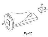
- FIG. 2Cis a diagram depicting an exemplary piping structure for guiding light through the imager housing
- FIG. 3is a cross-sectional view of a imager housing having a sealable user adjustable focus mechanism
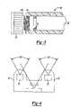
- FIG. 4is a cross-sectional schematic view of the imager housing
- FIGS. 5A-5Care perspective views of exemplary attachments for the imager housing
- FIG. 6Ais a perspective view illustrating the engagement area for an exemplary attachment on the imager housing
- FIG. 6Bis a perspective view illustrating an exemplary attachment coupled to the imager housing
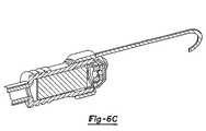
- FIG. 6Cis a perspective view illustrating an alternative coupling means for attaching an attachment to the imager housing
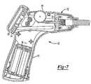
- FIG. 7is a cross-sectional view of an exemplary display housing
- FIGS. 8A and 8Bare fragmentary sectional views illustrating the coupling of the flexible cable to the display housing
- FIG. 9is a block diagram of the operational components which comprise the inspection device.
- FIG. 10is a perspective view illustrating a modular design for the inspection device
- FIGS. 11A and 11Bare cross-sectional view of a detachable coupling which may be used in the inspection device;
- FIG. 12is a cross-sectional view of a secondary connector which may be used with the inspection device
- FIG. 13is a perspective view of another exemplary detachable coupling
- FIGS. 14A-14Fare cross sectional views illustrating the assembly process for the detachable coupling
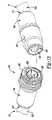
- FIG. 15is a perspective view of the detachable coupling
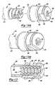
- FIGS. 16A-16Bare perspective views of a portion of another exemplary detachable coupling.
- FIG. 17is a cross sectional view illustrating the portion of the detachable coupling of FIG. 16B .
- FIG. 1illustrates an exemplary embodiment of a remote inspection device 10 .
- the remote inspection device 10is generally comprised of three primary components: a display housing 12 , an imager housing 14 and a flexible cable 16 interconnecting the display housing 12 to the imager housing 14 .
- the flexible cable 16may be bent or curved as it is pushed into visually obscured areas, such as pipes, walls, etc.
- the flexible cable 16is a ribbed cylindrical conduit having an outer diameter in the range of 1 cm.
- the conduitcan be made of either a metal, plastic or composite material. Smaller or larger diameters may be suitable depending on the application. Likewise, other suitable constructions for the flexible cable 16 are also contemplated by this disclosure.
- the imager housing 14is coupled to a distal end of the flexible cable 16 .
- the imager housing 14is a substantially cylindrical shape that is concentrically aligned with the flexible cable 16 .
- the imager housing 14may take other shapes.
- an outer diameter of the cylindrical imager housing 14is preferably sized to be substantially equal to or greater than the outer diameter of the flexible cable 16 .
- the imager housing 14is configured to house an imaging device 22 and one or more light sources 24 .
- the imaging device 22is embedded in an outwardly facing end of the imager housing.
- the imaging device 22is coupled to an end of a circuit board 21 which in turn slides into an internal cavity of the imager housing 14 .
- the imaging device 22is operable to capture an image of a viewing area proximate to the outwardly facing end of the imager housing 14 .
- the imaging device 22may be implemented using a charge-coupled device (CCD), a CMOS-based image sensor, a digital image sensor, or other types of commercially available imaging devices.
- Image datais focused onto the imaging device 22 by a lens assembly 23 positioned adjacent to the imaging device 22 .
- the imaging device 22 and lens assembly 23provides a fixed focus at approximately four to ten inches from the end of the imager housing.
- the inspection device 10may provide an adjustable focus.
- a user adjusted focus mechanism 30is shown in FIG. 3 .
- the lens assembly 23can be moved axially nearer or farther from the imager 22 . This movement changes the focus of the imaging device.
- a seal 31must be provided to prevent foreign materials from entering the mechanism.
- the imaging device and lens assemblymay be replaced with an auto-focus camera module. In this instance, a more sophisticated processor and drive motor assembly is needed to drive the camera module.
- one or more light sources 24 for illuminating the viewing areaare also electrically connected to the circuit board 21 .
- two light emitting diodesLEDs
- the LEDsprotrude outwardly from the circuit board such that the imaging device 22 and lens assembly 23 is recessed between the two LEDs as shown in FIG. 4 .
- the LEDsmay optionally be connected to a separate circuit board residing in the camera head.
- the LEDs 24may be recessed behind the imaging device 22 and/or lens assembly, such that light from the LEDs is transferred or piped to an emitting point which extends above and beyond the imaging device 22 .
- An exemplary piping structureis shown in FIG. 2C . In either instance, recessing the imaging device and lens assembly behind the light emitting point reduces the amount of backscattered or interfering light from the LEDs.
- a transparent cap 26encloses these components within the imager housing 14 .
- the cap 26may be made of an acrylic material that enables light to project from the LEDs into the viewing area and return from the viewing area to the imaging device. Other types of durable transparent material may be used in place of acrylic.
- each of the protruding LEDsis encased by a nipple 27 formed in the cap 26 .
- each LEDshould preferably project light proximate to the view angle of the imager at a 60 degree view angle away from the image housing 14 . LEDs having such a view angle may be used. However, LED's having a 132 degree view angle provide a more inexpensive alternative.
- the ends of the nipples 27may be curved to form a lens which focuses the light from the LEDs to a 60 degree view angle as shown in FIG. 4 .
- the cap 26may also serve as a lens for the light sources.
- the cap 26is preferably ultrasonically welded to the outwardly facing end of the imager housing 14 , thereby creating a sealed enclosure; otherwise, techniques for sealing the cap to the imager housing are also contemplated.
- An alternative embodiment for the imager housing 14is shown in FIG. 2B .
- the imager housing 14couples to the flexible cable 16 by way of a threaded sleeve 29 integrally formed at one end of the imager housing 14 .
- the threaded sleeve 29 on the imager housingscrews into a grooved portion from along an interior surface of a coupling formed on the distal end of the flexible cable.
- the sleeve and couplingeach provide an axial passageway for a plurality of wires that are electrically connected between the circuit board in the imager housing and the display housing.
- the plurality of wiresmay or may not be further encased in a protective cable.
- an attachment 51may be removably coupled to the imager housing 14 .
- the attachment 51is generally comprised of a finger portion 53 which extends in parallel to the axis of the cylindrical imager housing and beyond an outwardly facing end of the housing, and a clip 52 that attaches to the cylindrical housing.
- a distal end of the finger portion 53may be further configured to retrieve or otherwise manipulate objects proximate to the end of the imager housing 14 .
- the attachment 51may be configured with a hook as shown in FIG. 5A or with a magnet as shown in FIG. 5B .
- the attachmentmay be a mirror as shown in FIG. 5C .
- Other configurations, such as a loop, lance, or cutting device,are also contemplated by this disclosure.
- the imager housingprovides an engagement area for the attachment 51 as shown in FIG. 6A .
- the engagement areais comprised of an annular recess 62 formed in the outer surface of the imager housing. Within the annular recess, two opposing cutaways 62 are also formed, where each cutaway 62 defines a recessed rectangular planar surface 63 having a longitudinal axis 64 in parallel with the axis of the cylindrical imager housing. A radial surface 66 is formed between the two opposing cutaways.
- the clip 52is further defined as a cylindrical band 54 having a radial gap 55 formed therein, such that the radial gap 55 of the clip 52 is slightly larger than the remaining radial surface 66 .
- annular recess 62is sized to receive the cylindrical band 54 of the clip.
- the engagement areamay further include a locking groove 67 formed in the radial surface thereof and extends in parallel to the axis of the cylindrical imager housing. The locking groove 67 is sized to receive the finger portion 53 of the attachment.
- the attachment 51is coupled to the imager housing 14 by sliding the cylindrical band 54 over the recessed portion of the housing 14 and into the annular recess 62 . Recessed into the annular recess prevent the attachment from sliding forward or backwards along the imaging housing. The attachment 51 is then rotated 90 degrees around the axis of the housing until the finger portion 53 of the attachment 51 is recessed into the locking groove, thereby preventing attachment 51 from rotating about. The spring load of the band pulls the finger portion into the locking groove 67 to further prevent detachment from the imager housing. It is understood that the clip mechanism is a non-limiting example of how the attachment may be removably coupled to the imager housing.
- FIG. 6Cillustrates a threaded coupling between the attachment 51 and the imager housing 14 . Other coupling means, such as magnetic, are also contemplate by this disclosure.
- the display housing 12is coupled to a proximate end of the flexible cable 16 .
- the display housing 12is in the shape of a pistol.
- the display housing 12includes a handle portion 71 configured to be grasped by an operator of the device and a protruding portion 72 extending away from the user when grasped by the user, such that the protruding portion forms an obtuse angle relative to the handle portion of the housing display.
- Other handheld configurations for the display housingalso fall within the broader aspects of this disclosure.
- a threaded male connector 82 formed on the proximate end of the flexible cable 16is used to couple the cable to the display housing 12 as best seen in FIGS. 8A and 8B .
- a knurled nut 84is fixed with the nut retainer 86 .
- the male connector 82is screwed into the knurled nut 84 , thereby coupling the flexible cable 16 to the nut retainer 86 .
- the nut retaineris then attached into the protruding portion of the display housing 12 .
- Other types of connectionsare contemplated by this disclosure.
- the display housing 12is configured to support the remaining operational components of the inspection device.
- the operational componentsinclude a display device 73 , an interface board 74 , a power switch 75 and a power source 76 (i.e., 4 AA alkaline batteries).
- the display device 73is preferably orientated towards the operator as the operator grasps the handle portion 71 of the device.
- a liquid crystal displayis presently preferred, it is understood that other types of display devices, such a cathode ray tube or a LED display, may also be used.
- the power switch 75is interposed between the power source 76 and the remaining operational components. When actuated by an operator to an ON position, power is supplied from the power source 76 to the interface board 74 . The interface board 74 in turn powers the display device 73 and the imaging device 22 .
- the power switch 75is further operable to control the intensity of the LEDs. To do so, power is also supplied to an LED interface board 91 .
- the LED interface board 91in turn sends a control signal to the LEDs based on the setting of the power switch 75 . As the dial is rotated further away from an ON position, the intensity of the LEDs is increased. In this way, the operator can adjust the illumination of the viewing area, thereby improving the quality of the acquired images.
- Alternative embodiments of the inspection devicemay employ other user actuated controls.
- the inspection devicemay include controls for the contrast of the display device, on-screen display or for a zoom function of the imaging device.
- the imaging device 22begins capturing images and transmitting the image data as a video signal to a video decoder 92 residing on the interface board 74 .
- the video decoder 92decodes the video signal and passes it through another interface to the display device 73 .
- the display device 73is then operable to display the video images to the operator.
- the imager housingis connected by a four wire twisted pair cable to the display housing.
- Functions for each wireare specified as follows: a power wire for delivering electrical power to the imaging device, a video wire for transporting the captured image data (e.g., a NTSC signal) from the imager back to the interface board, a control signal for varying the intensity of the light source and a ground connection. It is envisioned that more or less wires may be needed to support different functionality.
- the inspection devicemay provide an image self-righting feature. As the camera head is pushed into inspection areas, it may get twisted so that the images displayed to the operator are disoriented. To orientate the images, an accelerometer is placed in the imager housing. The accelerometer is operable to report the position of the camera head in relation to a sensed gravity vector. Given the position data and the image data, a microprocessor residing in the display housing can apply a known rotation algorithm (e.g., rotation matrix) to the image data. In this way, the image data is always presented upright to the operator.
- a known rotation algorithme.g., rotation matrix
- the remote inspection devicemay be designed to be modular as shown in FIG. 10 .
- the more expensive processing componentssuch that the LCD, are disposed in the display housing; whereas, lesser expensive components are used to construct the imager housing. Modularity enables the lesser expensive components to be interchanged or replaced as needed.
- a detachable coupling between the imager housing and the flexible cableenables imager housings of varying sizes to be used with the same display housing.
- the flexibility allowed by the modularity of this devicealso allows the cost efficient manufacture of easily replaceable imager heads that could be fixed at any desired spherical orientation in regard to the central axis of the cable or the imager head.
- a first imager head 14 ′may be constructed as described above with the imaging device orientated along the central axis of the imager head; whereas, a second imager head 14 ′′ provides an imaging device orientated at 90 degrees to the central axis of the imager head.
- Imager headshave other orientations are also contemplated.
- a second detachable coupling between the display housing and the flexible cableenables the use of different types of cables while retaining the same imager housing.
- cablesmay vary in length from 3 feet to more than 50 feet and may vary in diameter from less than an inch to a couple of inches in diameter.
- different cablesmay have different flexibilities, stiffnesses, spring tensions, obedient cable properties, tape measure material similarities, fish-tape or fish-stick similarities, push-cable similarities, etc.
- the remote inspections devicemay be sold as a kit having a display housing 12 , at least one imager head 14 and a set of different cables having different constructs. Additional imager heads may be included in the kit or sold individually.
- a first type of cable attachment along with a particular image headmay be selected and coupled to the display housing.
- the usermay detach the image head and attach an image head which provides a different function.
- the usermay also need to replace the cable attachment.
- the userfurther detaches the first type of cable attachment and attaches a second type of cable attachment having a different construct than the first type of cable attachment.
- the second type of cable attachmentmay have a different length, diameter, or flexibility than the first type of cable attachment.
- the userselects and attaches a suitable image head to the second type of cable attachment. In this way, the more expensive display housing may be configured with different and less expensive components tailored to a particular task.
- FIGS. 11A and 11Billustrate an exemplary detachable coupling 110 which may be interposed between the imager housing 14 and the flexible cable 16 .
- a cylindrical sleeve 29having an outer threaded portion protrudes from the housing.
- a male connector 112is fixed within an axial passageway of the threaded sleeve.
- the male connector 112is in turn electrically connected via the applicable wires to the imaging device and light sources.
- a corresponding female connector 114is coupled to the distal end of the flexible cable 16 .
- the female connector 114is electrically connected to wires which extend through the flexible cable 16 to the display housing. By plugging the male connector 112 into the female connector 114 , the imager housing 14 is electrically connected to the flexible cable 16 .
- a cylindrical coupling 116is also disposed on the distal end of the flexible cable 16 .
- the cylindrical coupling 116further provides an internal grooved portion 117 which mates with the threaded portion of the sleeve on the imager housing.
- the cylindrical coupling 116is slid over the female connector and screwed onto the threaded portion of the sleeve, thereby encasing the electrical connection within the coupling.
- An O-ring 119 or other sealing componentis preferably disposed between the inner surface of the cylindrical coupling and the outer surface of the flexible cable.
- a detachable coupling having a similar constructionmay be interposed between flexible cable and the display housing. Moreover, it is envisioned that other types of detachable couplings may be employed to achieve the modularity.
- a secondary connector 120may be interposed between the imager housing 14 and the flexible cable 16 as shown in FIG. 12 .
- the secondary connector 120is designed to be more flexible than the flexible cable, thereby providing strain relief as the imager housing is snaked into an inspection area.
- a corrugated outer surface of the secondary connector 120provides its flexibility.
- a cylindrical sleeve having an outer threaded portionprotrudes from the housing.
- one end of the secondary connector 120is overmolded around the cylindrical sleeve to form a coupling between the image housing 14 and the secondary connector.
- the other side of the secondary connectorcan be constructed in manner described above for coupling to the flexible cable. Again, this type of secondary connector may also be interposed between the other end of the flexible cable and the display housing.
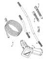
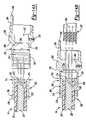
- FIGS. 13-15illustrate another exemplary detachable coupling 200 and the assembly thereof.
- coupling 200may be used to interconnect different components of inspection device 10 .
- coupling 200can attach imager housing 14 and flexible cable 16 as illustrated.
- flexible cable 16In this exemplary illustration of flexible cable 16 , wires 220 are covered by an outer jacket 222 , and an end 224 is defined. It should be understood that, according to the principles of the present disclosure, flexible cable 16 can have a variety of components and configurations.
- coupling 200includes a deformable ferrule or ferrule component 202 , an exterior metal connector or casing 206 , and an electrical connector 208 in a first assembly of components associated with flexible cable 16 .
- coupling 200 and the components thereofe.g. ferrule components, casings, and electrical connectors
- coupling 200 and the components thereofcan vary in many ways. Accordingly, it should be understood that the descriptions herein of coupling 200 and the components thereof are exemplary in nature.
- Exemplary ferrule 202has a generally annular shape and is disposed around flexible cable 16 with an inside surface 230 engaging outer jacket 222 .
- Ferrule 202further includes an end cap 232 engaged with end 224 of flexible cable 16 .
- Wires 220extend through an aperture 234 in end cap 232 .
- End cap 232provides for a fixed position of ferrule 202 along the length of flexible cable 16 .
- end cap 232provides for simple assembly of ferrule 202 and flexible cable 16 , as ferrule 202 is disposed on flexible cable 16 until end 224 engages end cap 232 .
- ferrule 202includes an outside surface 236 configured to engage with casing 206 .
- Outside surface 236can have a diameter D 1 sized to provide an interference fit with casing 206 , as explained in more detail herein.
- Ferrule 202also has a sloped end surface 238 at the end thereof opposite end cap 232 . As explained in more detail herein, sloped end surface 238 helps facilitate the movement of coupling 200 through confined spaces.
- ferrule 202has protrusions 240 extending from outside surface 236 . As illustrated in the Figures, protrusions 240 can be in the form of ridges or splines extending around outer surface 236 . As explained in more detail herein, protrusions 240 engage with complementary features of casing 206 to prevent relative axial movement therebetween. As used herein, the term “axial movement” refers to movement along the length of components of coupling 200 .
- Ferrule 202is preferably comprised of an electrically insulating material such as plastic or nylon. As explained herein, in combination with other components of coupling 200 , ferrule 202 electrically isolates coupling 200 from flexible cable 16 and, thus, the remainder of inspection device 10 . Furthermore, as a diameter D 1 of outside surface 236 can be sized to provide an interference fit with casing 206 , ferrule 202 can be made of a deformable material.
- Exemplary casing 206includes a cylindrical portion 250 which is disposed over ferrule 202 and flexible cable 16 .
- Cylindrical portion 250 of casing 206 and ferrule 202have a sealed engagement to prevent fluid communication therebetween (e.g., to provide a watertight seal).
- the engagement of ferrule 202 and cylindrical portion 250also provide a sealed engagement between ferrule 202 and flexible cable 16 . Therefore, coupling 200 is watertight between flexible cable 16 and cylindrical portion 250 of casing 206 .
- ferrule 202can be press fit into cylindrical portion 250 , as an inside surface 252 of cylindrical portion 250 can have a diameter D 2 smaller than the diameter D 1 of a complementary portion of outside surface 236 of ferrule 202 .
- casing 206can deform ferrule 202 .
- casing 206has a plurality of recesses 254 formed in inside surface 252 complementary to protrusions 240 .
- Ferrule 202is swaged into casing 206 so that protrusions 240 extend into recesses 254 .
- The. engagement of protrusions 240 and recesses 254prevent relative axial movement between ferrule 202 and casing 206 .
- recesses 254can be in the form of grooves extending around inside surface 252 .
- Casing 206further includes a main portion 260 having an inside surface 262 and an outside surface 264 .
- inside surface 262is configured to support electrical connector 208 .
- a sloped portion 266 of outside surface 264helps facilitate the movement of coupling 200 through confined spaces.
- Main portion 260also has a tab 268 extending therefrom. Tab 268 is configured to prevent relative rotation within coupling 200 , as explained in more detail herein.
- Exemplary electrical connector 208is disposed within casing 206 and supported by inside surface 262 .
- electrical connector 208can be sized to have an interference fit with a portion of inside surface 262 to hold electrical connector 208 in place during assembly.
- Prongs 280extend from electrical connector 208 and are electrically connected to wires 220 .
- wires 220are soldered to electrical connector 208 .
- electrical connector 208isolates wires 220 and prongs 280 from casing 206 . It should be understood that electrical connector 208 can have a variety of components and configurations and can be connected to wires 220 in a variety of ways.
- exemplary casing 206can include a tap 282 proximate electrical connector 208 .
- a set screw 284is disposed within tap 282 . Set screw 284 is tightened to engage electrical connector 208 and to help secure electrical connector 208 relative to casing 206 .
- a space 290is defined within casing 206 and between ferrule 202 and electrical connector 208 as these components are assembled together.
- Wires 220extend through space 290 from end 224 of flexible cable 16 to electrical connector 208 .
- space 290can be filled or backpotted with an insulating or backpotting material 292 .
- Casing 206includes an aperture 294 in communication with space 290 .
- Set screw 284engages electrical connector 208 to hold electrical connector 208 in place, and insulating material 292 is inserted through aperture 294 and fills space 290 .
- Insulating material 292reduces and/or eliminates the airspace between ferrule 202 and electrical connector 208 .
- Insulating material 292electrically isolates the wires 220 extending through space 290 from casing 206 and serves as an adhesive to help hold electrical connector 208 in place.
- insulating material 292increases the waterproofing, vibration resistance, and durability of coupling 200 .
- insulating material 292can be made of a variety of materials.
- insulating material 292can be a foam, epoxy, or glue. As such, insulating material 292 can be configured to harden in space 290 .
- coupling 200can have a second assembly of components associated with a cable segment 300 of imager housing 14 similar to the first assembly of components associated with flexible cable 16 . Accordingly, it should be understood that the descriptions herein equally apply to similar components, unless otherwise noted.
- Coupling 200has a ferrule 302 engaged with cable segment 300 , a casing 306 disposed over ferrule 302 , and an electrical connector 308 supported within casing 306 in the second assembly of components.
- a space 310is defined within casing 306 and between ferrule 302 and electrical connector 308 .
- Space 310is filled with insulating material 312 through a aperture 314 in casing 306 .
- casing 306does not include a tab extending therefrom. Rather, as shown in FIG. 15 , casing 306 has a recess 320 formed therein. Recess 320 is complementary to tab 268 of casing 206 and receives tab 268 when the two assemblies of coupling 200 are mated together. With tab 268 disposed in recess 320 , casings 206 , 306 are inhibited from rotating relative to one another. This connection provides for torque resistance within the coupling 200 .
- Casing 306also includes a threaded tap 322 and a set screw 324 disposed within tap 322 . Similar to tap 282 and set screw 324 described herein, tap 322 is proximate electrical connector 308 , and set screw 324 is tightened to engage electrical connector 308 and to help secure electrical connector 308 relative to casing 306 .
- Electrical connector 308includes holes 330 formed herein. Holes 330 are electrically connected to wires 332 of cable segment 300 . Holes 330 have a complementary size and configuration to prongs 280 of electrical connector 208 . Holes 330 receive prongs 280 when the two assemblies of coupling 200 are mated together. Thereby, wires 220 of flexible cable 16 and wires 332 of cable segment 300 are electrically connected. Furthermore, the ferrules, electrical connectors, and insulating material together electrically isolate casings 206 , 306 from the wires and, therefore, the rest of inspection device 10 .
- Both wires 220 of flexible cable 16 and wires 332 of cable segment 300are coiled together. This configuration provides flexibility to the length of the electrical connection. Therefore, when flexible cable 16 or cable segment 300 is bent during use, or otherwise when a variation in connection length is needed during assembly, both wires 220 and 332 can accommodate a variety of connection lengths.
- coupling 200further includes a sleeve 340 disposed over and engaged with casings 206 , 306 .
- a threaded portion 342 on an inside surface 344 of sleeve 340engages a complementary threaded portion 348 on outside surface 236 of casing 206 .
- a shoulder 352 on inside surface 344 of sleeve 340engages a complementary shoulder 356 in casing 306 . Therefore, sleeve 340 can be tightened onto casing 206 while engaging casing 306 to secure the two assemblies of coupling 200 together.
- Sleeve 340can also have sealed engagements with casings 206 , 306 .
- a first sealing member 360is supported by casing 206 and engages inside surface 344 of sleeve 340 .
- a second sealing member 362is supported by casing 306 and also engages inside surface 344 of sleeve 340 .
- Sleeve 340further includes a sloped surface 370 proximate an end thereof. Sloped surface 370 , together with sloped portion 266 of outside surface 264 of casing 206 and with the sloped surfaces of the ferrules, facilitates the movement of coupling 200 through confined spaces. For example, if the coupling 200 is maneuvering through a confined space such as an angled plumbing fitting, the sloped surfaces inhibit coupling 200 from engaging an edge or other protrusion in a manner which would impede or prevent further travel of coupling 200 .
- Coupling 200can vary in many ways. The components thereof can have a variety of configurations and can include a variety of materials. Accordingly, it should be understood that the description of coupling 200 herein is exemplary in nature.
- ferrule 402can be included in a coupling according to the principles of the present disclosure such as is described herein with regard to ferrules 202 , 302 .
- Ferrule 402is disposed over a cable 410 .
- Cable 410has an outer jacket 422 .
- Outer jacket 422does not extend to an end 424 of cable 410 .
- an inner component 426is exposed.
- wires (not shown)can extend through cable 410 .
- Ferrule 402has a generally annular shape and is disposed around cable 410 with an inside surface 430 engaging outer jacket 422 and inner component 426 .
- Ferrule 402further includes an end cap 432 engaged with end 424 .
- An aperture 434is provided in end cap 432 so that wires (not shown) of cable 410 can extend therethrough.
- Ferrule 402also includes an outside surface 436 .
- Outside surface 436is configured to engage with a casing component in a similar way as described herein with respect to ferrules 202 , 302 .
- Ferrule 402also has a sloped end surface 438 at the end thereof opposite end cap 432 . As explained herein, such sloped surfaces help facilitate movement through confined spaces.
- ferrule 402has a single protrusion 440 extending from outside surface 436 . Similar to protrusions 240 of ferrule 202 described herein, protrusion 440 engages with a complementary feature of a casing or similar component to prevent relative axial movement therebetween. As illustrated in the Figures, protrusion 440 can be in the form of a ridge or spline extending around outer surface 436 .
- Ferrule 402is overmolded onto cable 410 .
- ferrule 402is molded into shape over cable 410 so that a portion of inside surface 430 engages outer jacket 422 and another portion of inside surface 430 engages inner component 426 with projections 442 extending from inside surface 430 into grooves 444 of inner component 426 . Therefore, ferrule 402 and cable 410 have a sealed engagement which inhibits fluid communication therebetween.
- Ferrule 402is also secured along to the axial direction of cable 410 .
- ferrule 402is formed with a key portion 446 complementary to a key portion 448 of inner component 426 . The key portions engage and inhibit relative rotation of ferrule 402 and inner component 426 . As such, the key portions inhibit the effects of rotational torque on the assembly.
- ferrule 402can otherwise be similar ferrules 202 , 302 described herein.
- ferrule 402can be comprised of an insulating material such as plastic or nylon.
- ferrule 402can be a deformable material.
- ferrule 402can be sized so as to provide an interference fit with a casing or similar component.
- a casing or similar componentcan be disposed over and engaged with ferrule 402 such that ferrule 402 provides a seal between cable 410 and the casing or similar component and such that ferrule 402 electrically isolates cable 410 and the casing or similar component.
Landscapes
- Health & Medical Sciences (AREA)
- Life Sciences & Earth Sciences (AREA)
- Surgery (AREA)
- Physics & Mathematics (AREA)
- Optics & Photonics (AREA)
- Engineering & Computer Science (AREA)
- Biomedical Technology (AREA)
- Molecular Biology (AREA)
- Pathology (AREA)
- Nuclear Medicine, Radiotherapy & Molecular Imaging (AREA)
- Biophysics (AREA)
- Heart & Thoracic Surgery (AREA)
- Medical Informatics (AREA)
- Radiology & Medical Imaging (AREA)
- Animal Behavior & Ethology (AREA)
- General Health & Medical Sciences (AREA)
- Public Health (AREA)
- Veterinary Medicine (AREA)
- Astronomy & Astrophysics (AREA)
- General Physics & Mathematics (AREA)
- Microelectronics & Electronic Packaging (AREA)
- Studio Devices (AREA)
Abstract
Description
Claims (38)
Priority Applications (3)
| Application Number | Priority Date | Filing Date | Title |
|---|---|---|---|
| US11/645,276US7384308B2 (en) | 2005-01-10 | 2006-12-22 | Detachable coupling for a remote inspection device |
| US11/895,516US7431619B2 (en) | 2006-06-30 | 2007-08-24 | Detachable coupling for a remote inspection device |
| US12/157,324US7581988B2 (en) | 2006-06-30 | 2008-06-09 | Detachable coupling for a remote inspection device |
Applications Claiming Priority (5)
| Application Number | Priority Date | Filing Date | Title |
|---|---|---|---|
| US11/032,275US20060155168A1 (en) | 2005-01-10 | 2005-01-10 | Optical snake |
| US11/328,603US7758495B2 (en) | 2005-01-10 | 2006-01-10 | Remote inspection device |
| US11/480,329US7584534B2 (en) | 2005-01-10 | 2006-06-30 | Remote inspection device |
| US84858606P | 2006-09-29 | 2006-09-29 | |
| US11/645,276US7384308B2 (en) | 2005-01-10 | 2006-12-22 | Detachable coupling for a remote inspection device |
Related Parent Applications (1)
| Application Number | Title | Priority Date | Filing Date |
|---|---|---|---|
| US11/480,329Continuation-In-PartUS7584534B2 (en) | 2005-01-10 | 2006-06-30 | Remote inspection device |
Related Child Applications (2)
| Application Number | Title | Priority Date | Filing Date |
|---|---|---|---|
| US11/895,516Continuation-In-PartUS7431619B2 (en) | 2006-06-30 | 2007-08-24 | Detachable coupling for a remote inspection device |
| US12/157,324ContinuationUS7581988B2 (en) | 2006-06-30 | 2008-06-09 | Detachable coupling for a remote inspection device |
Publications (2)
| Publication Number | Publication Date |
|---|---|
| US20070117437A1 US20070117437A1 (en) | 2007-05-24 |
| US7384308B2true US7384308B2 (en) | 2008-06-10 |
Family
ID=46326911
Family Applications (1)
| Application Number | Title | Priority Date | Filing Date |
|---|---|---|---|
| US11/645,276ActiveUS7384308B2 (en) | 2005-01-10 | 2006-12-22 | Detachable coupling for a remote inspection device |
Country Status (1)
| Country | Link |
|---|---|
| US (1) | US7384308B2 (en) |
Cited By (55)
| Publication number | Priority date | Publication date | Assignee | Title |
|---|---|---|---|---|
| US20060025650A1 (en)* | 2002-10-03 | 2006-02-02 | Oren Gavriely | Tube for inspecting internal organs of a body |
| US20060167340A1 (en)* | 2005-01-10 | 2006-07-27 | Pease Alfred A | Optical snake |
| US20060281972A1 (en)* | 2005-01-10 | 2006-12-14 | Pease Alfred A | Remote inspection device |
| US20090229842A1 (en)* | 2008-03-07 | 2009-09-17 | Rick Gray | Battery pack for use with a power tool and a non-motorized sensing tool |
| US7628646B1 (en)* | 2008-07-01 | 2009-12-08 | Cablesat International Co., Ltd. | Cable connector and method of assembling cable connector and cable |
| US20100095542A1 (en)* | 2008-10-16 | 2010-04-22 | Romer, Inc. | Articulating measuring arm with laser scanner |
| US20110107614A1 (en)* | 2009-11-06 | 2011-05-12 | Hexagon Metrology Ab | Enhanced position detection for a cmm |
| US20110227012A1 (en)* | 2008-12-02 | 2011-09-22 | Swisscom Ag | Cable pusher guiding system, method and device |
| US20120048617A1 (en)* | 2010-08-25 | 2012-03-01 | Panasonic Electric Works Co., Ltd. | Power supply control device |
| US8189043B2 (en) | 2008-03-07 | 2012-05-29 | Milwaukee Electric Tool Corporation | Hand-held visual inspection device for viewing confined or difficult to access locations |
| US8926502B2 (en) | 2011-03-07 | 2015-01-06 | Endochoice, Inc. | Multi camera endoscope having a side service channel |
| US9049351B2 (en) | 2010-05-03 | 2015-06-02 | Inspectron, Inc. | Insulator design for video inspection devices |
| US9101266B2 (en) | 2011-02-07 | 2015-08-11 | Endochoice Innovation Center Ltd. | Multi-element cover for a multi-camera endoscope |
| US9101268B2 (en) | 2009-06-18 | 2015-08-11 | Endochoice Innovation Center Ltd. | Multi-camera endoscope |
| US9101287B2 (en) | 2011-03-07 | 2015-08-11 | Endochoice Innovation Center Ltd. | Multi camera endoscope assembly having multiple working channels |
| US9107573B2 (en) | 2012-10-17 | 2015-08-18 | Karl Storz Endovision, Inc. | Detachable shaft flexible endoscope |
| US20150270656A1 (en)* | 2013-02-25 | 2015-09-24 | Pct International, Inc. | Coaxial Cable Connector With Compressible Inner Sleeve |
| US9314147B2 (en) | 2011-12-13 | 2016-04-19 | Endochoice Innovation Center Ltd. | Rotatable connector for an endoscope |
| US9320419B2 (en) | 2010-12-09 | 2016-04-26 | Endochoice Innovation Center Ltd. | Fluid channeling component of a multi-camera endoscope |
| US9402533B2 (en) | 2011-03-07 | 2016-08-02 | Endochoice Innovation Center Ltd. | Endoscope circuit board assembly |
| US9468367B2 (en) | 2012-05-14 | 2016-10-18 | Endosee Corporation | Method and apparatus for hysteroscopy and combined hysteroscopy and endometrial biopsy |
| US9492063B2 (en) | 2009-06-18 | 2016-11-15 | Endochoice Innovation Center Ltd. | Multi-viewing element endoscope |
| US9554692B2 (en) | 2009-06-18 | 2017-01-31 | EndoChoice Innovation Ctr. Ltd. | Multi-camera endoscope |
| US9560953B2 (en) | 2010-09-20 | 2017-02-07 | Endochoice, Inc. | Operational interface in a multi-viewing element endoscope |
| US9560954B2 (en) | 2012-07-24 | 2017-02-07 | Endochoice, Inc. | Connector for use with endoscope |
| US9622646B2 (en) | 2012-06-25 | 2017-04-18 | Coopersurgical, Inc. | Low-cost instrument for endoscopically guided operative procedures |
| US9642513B2 (en) | 2009-06-18 | 2017-05-09 | Endochoice Inc. | Compact multi-viewing element endoscope system |
| US9655502B2 (en) | 2011-12-13 | 2017-05-23 | EndoChoice Innovation Center, Ltd. | Removable tip endoscope |
| US9706903B2 (en) | 2009-06-18 | 2017-07-18 | Endochoice, Inc. | Multiple viewing elements endoscope system with modular imaging units |
| US9713417B2 (en) | 2009-06-18 | 2017-07-25 | Endochoice, Inc. | Image capture assembly for use in a multi-viewing elements endoscope |
| US9736342B2 (en) | 2012-10-19 | 2017-08-15 | Milwaukee Electric Tool Corporation | Visual inspection device |
| US9814374B2 (en) | 2010-12-09 | 2017-11-14 | Endochoice Innovation Center Ltd. | Flexible electronic circuit board for a multi-camera endoscope |
| US9872609B2 (en) | 2009-06-18 | 2018-01-23 | Endochoice Innovation Center Ltd. | Multi-camera endoscope |
| US9901244B2 (en) | 2009-06-18 | 2018-02-27 | Endochoice, Inc. | Circuit board assembly of a multiple viewing elements endoscope |
| US9986899B2 (en) | 2013-03-28 | 2018-06-05 | Endochoice, Inc. | Manifold for a multiple viewing elements endoscope |
| US9993142B2 (en) | 2013-03-28 | 2018-06-12 | Endochoice, Inc. | Fluid distribution device for a multiple viewing elements endoscope |
| US10036627B2 (en) | 2014-09-19 | 2018-07-31 | Hexagon Metrology, Inc. | Multi-mode portable coordinate measuring machine |
| US10080486B2 (en) | 2010-09-20 | 2018-09-25 | Endochoice Innovation Center Ltd. | Multi-camera endoscope having fluid channels |
| US10149602B2 (en) | 2011-07-11 | 2018-12-11 | Ambu A/S | Endobronchial tube with integrated image sensor and a cleaning nozzle arrangement |
| US10165929B2 (en) | 2009-06-18 | 2019-01-01 | Endochoice, Inc. | Compact multi-viewing element endoscope system |
| US10203493B2 (en) | 2010-10-28 | 2019-02-12 | Endochoice Innovation Center Ltd. | Optical systems for multi-sensor endoscopes |
| US10245402B2 (en) | 2011-07-11 | 2019-04-02 | Ambu A/S | Endobronchial tube with integrated image sensor |
| US10302598B2 (en) | 2016-10-24 | 2019-05-28 | General Electric Company | Corrosion and crack detection for fastener nuts |
| US10441134B2 (en) | 2011-05-03 | 2019-10-15 | Coopersurgical, Inc. | Method and apparatus for hysteroscopy and endometrial biopsy |
| US10499794B2 (en) | 2013-05-09 | 2019-12-10 | Endochoice, Inc. | Operational interface in a multi-viewing element endoscope |
| US10702305B2 (en) | 2016-03-23 | 2020-07-07 | Coopersurgical, Inc. | Operative cannulas and related methods |
| US11253169B2 (en) | 2009-09-14 | 2022-02-22 | Sotera Wireless, Inc. | Body-worn monitor for measuring respiration rate |
| US11278190B2 (en) | 2009-06-18 | 2022-03-22 | Endochoice, Inc. | Multi-viewing element endoscope |
| US11547275B2 (en) | 2009-06-18 | 2023-01-10 | Endochoice, Inc. | Compact multi-viewing element endoscope system |
| US11751032B2 (en) | 2017-04-24 | 2023-09-05 | Pilot, Inc. | Bluetooth enabled snake cam |
| US11864734B2 (en) | 2009-06-18 | 2024-01-09 | Endochoice, Inc. | Multi-camera endoscope |
| US11887502B2 (en) | 2018-01-04 | 2024-01-30 | Applied Medical Resources Corporation | Surgical simulation camera scope |
| US12137873B2 (en) | 2009-06-18 | 2024-11-12 | Endochoice, Inc. | Compact multi-viewing element endoscope system |
| US12204087B2 (en) | 2010-10-28 | 2025-01-21 | Endochoice, Inc. | Optical systems for multi-sensor endoscopes |
| US12220105B2 (en) | 2010-06-16 | 2025-02-11 | Endochoice, Inc. | Circuit board assembly of a multiple viewing elements endoscope |
Families Citing this family (24)
| Publication number | Priority date | Publication date | Assignee | Title |
|---|---|---|---|---|
| US8269829B2 (en)* | 2008-01-02 | 2012-09-18 | Perceptron, Inc. | Imager assembly for remote inspection device |
| US8033678B2 (en)* | 2008-04-14 | 2011-10-11 | Jason Patterson | Screw on lighted end attachment for use with a flexible snake |
| US20110317064A1 (en) | 2010-06-24 | 2011-12-29 | Watts Fred S | Remote Inspection Device |
| US10342619B2 (en) | 2011-06-15 | 2019-07-09 | Brainlab Ag | Method and device for determining the mechanical axis of a bone |
| CN105246428B (en)* | 2013-01-11 | 2019-09-27 | 美的洛博迪克斯公司 | Radial type surgical instruments and its configuration method |
| US10054753B2 (en)* | 2014-10-27 | 2018-08-21 | Commscope Technologies Llc | Fiber optic cable with flexible conduit |
| WO2016137838A1 (en) | 2015-02-23 | 2016-09-01 | Xiaolong Ouyang | Handheld surgical endoscope |
| US10869592B2 (en) | 2015-02-23 | 2020-12-22 | Uroviu Corp. | Handheld surgical endoscope |
| US10292571B2 (en)* | 2015-02-23 | 2019-05-21 | Uroviu Corporation | Handheld surgical endoscope with wide field of view (FOV) and illumination brightness adjusted by area within the FOV |
| AU2015207954C1 (en) | 2015-07-31 | 2022-05-05 | Adc Communications (Australia) Pty Limited | Cable breakout assembly |
| EP3403125B1 (en) | 2016-03-18 | 2021-07-14 | Commscope Technologies LLC | Fiber-optic cable fanout conduit arrangement and method for organizing optical fibers |
| US10890730B2 (en) | 2016-08-31 | 2021-01-12 | Commscope Technologies Llc | Fiber optic cable clamp and clamp assembly |
| US11832797B2 (en) | 2016-09-25 | 2023-12-05 | Micronvision Corp. | Endoscopic fluorescence imaging |
| US11684248B2 (en) | 2017-09-25 | 2023-06-27 | Micronvision Corp. | Endoscopy/stereo colposcopy medical instrument |
| US10914909B2 (en) | 2016-10-13 | 2021-02-09 | Commscope Technologies Llc | Fiber optic breakout transition assembly incorporating epoxy plug and cable strain relief |
| CN110622051A (en) | 2017-05-08 | 2019-12-27 | 康普技术有限责任公司 | Optical fiber branch transition assembly |
| US12268358B2 (en) | 2019-12-05 | 2025-04-08 | Uroviu Corp. | Portable endoscope with side-mountable disposable portion |
| US11771304B1 (en)* | 2020-11-12 | 2023-10-03 | Micronvision Corp. | Minimally invasive endoscope |
| US11980342B2 (en) | 2020-11-12 | 2024-05-14 | Micronvision Corp. | Minimally invasive endoscope |
| CN118177700A (en)* | 2018-01-05 | 2024-06-14 | 波士顿科学国际有限公司 | Fluorophore imaging device, system and method for endoscopic surgery |
| US10433717B1 (en) | 2018-06-28 | 2019-10-08 | Meditrina, Inc. | Endoscope having size-adjustable working channel |
| CN109994864A (en)* | 2019-04-15 | 2019-07-09 | 珠海格力电器股份有限公司 | Sectional type connection structure and be equipped with electrical apparatus of this structure |
| EP4003138A4 (en) | 2019-07-25 | 2023-08-30 | Uroviu Corp. | DISPOSABLE ENDOSCOPY NEEDLE WITH INTEGRATED GRIPPER |
| US20230056943A1 (en)* | 2019-12-13 | 2023-02-23 | Dinesh Vyas | Stapler apparatus and methods for use |
Citations (33)
| Publication number | Priority date | Publication date | Assignee | Title |
|---|---|---|---|---|
| US3296363A (en)* | 1964-05-28 | 1967-01-03 | Amp Inc | Crimped coaxial cable connection with knurled extension |
| US4467802A (en) | 1980-03-31 | 1984-08-28 | Harald Maslanka | Surgical gripping instrument |
| US4471766A (en) | 1977-11-24 | 1984-09-18 | Inbae Yoon | Ring applicator with an endoscope |
| US4779130A (en) | 1985-01-14 | 1988-10-18 | Olympus Optical Co., Ltd. | Endoscope having a solid-state image sensor and shield therefor |
| US5433725A (en) | 1991-12-13 | 1995-07-18 | Unisurge, Inc. | Hand-held surgical device and tools for use therewith, assembly and method |
| US5527261A (en) | 1994-08-18 | 1996-06-18 | Welch Allyn, Inc. | Remote hand-held diagnostic instrument with video imaging |
| US5651699A (en)* | 1994-03-21 | 1997-07-29 | Holliday; Randall A. | Modular connector assembly for coaxial cables |
| US5667473A (en) | 1994-03-18 | 1997-09-16 | Clarus Medical Systems, Inc. | Surgical instrument and method for use with a viewing system |
| US5754220A (en) | 1996-04-26 | 1998-05-19 | Emerson Electric Company | Apparatus for inspecting the interior of pipes |
| US5752973A (en) | 1994-10-18 | 1998-05-19 | Archimedes Surgical, Inc. | Endoscopic surgical gripping instrument with universal joint jaw coupler |
| US5928137A (en) | 1996-05-03 | 1999-07-27 | Green; Philip S. | System and method for endoscopic imaging and endosurgery |
| US5986752A (en) | 1996-11-18 | 1999-11-16 | Moritex Corporation | Bore scope |
| US6043842A (en) | 1996-12-31 | 2000-03-28 | Olympus America Inc. | Remote surveillance device |
| US6059719A (en) | 1997-08-06 | 2000-05-09 | Olympus Optical Co., Ltd. | Endoscope system |
| US6086528A (en) | 1997-09-11 | 2000-07-11 | Adair; Edwin L. | Surgical devices with removable imaging capability and methods of employing same |
| US6091453A (en) | 1996-07-29 | 2000-07-18 | Coan; Steven | Hand held remote camera |
| US6221077B1 (en) | 2000-02-28 | 2001-04-24 | Beere Precision Medical Instruments, Inc. | Human spine fixation template and method of making same |
| US6369849B1 (en) | 1999-01-28 | 2002-04-09 | Vosi Technologies, Inc. | Remote inspection device |
| US6419626B1 (en) | 1998-08-12 | 2002-07-16 | Inbae Yoon | Surgical instrument endoscope with CMOS image sensor and physical parameter sensor |
| US6530807B2 (en)* | 2000-05-10 | 2003-03-11 | Thomas & Betts International, Inc. | Coaxial connector having detachable locking sleeve |
| US6538732B1 (en) | 1999-05-04 | 2003-03-25 | Everest Vit, Inc. | Inspection system and method |
| US6599238B2 (en) | 1997-11-07 | 2003-07-29 | Matsushita Electric Industrial Co., Ltd. | Video scope with discriminating cover |
| US20040054254A1 (en) | 2002-09-13 | 2004-03-18 | Kiyoshi Miyake | Endoscope apparatus |
| US20040097130A1 (en)* | 2002-11-20 | 2004-05-20 | Holliday Randall A. | Universal crimping connector |
| US20040110418A1 (en)* | 2002-12-06 | 2004-06-10 | Holliday Randall A. | Mini-coax cable connector and method of installation |
| US20040193007A1 (en) | 2002-01-04 | 2004-09-30 | Stephen Martone | Endoscope assemblies having working channels with reduced bending and stretching resistance |
| US20040198095A1 (en)* | 2002-12-03 | 2004-10-07 | Laverick Eric W. | Compression BNC connector |
| US20050048836A1 (en)* | 2003-03-18 | 2005-03-03 | Holliday Randall A. | Universal crimping connector |
| US6875169B2 (en) | 2002-10-31 | 2005-04-05 | Karl Storz Gmbh & Co. Kg | Camera unit with a coupling for a detachable light and image guide |
| US7048579B2 (en)* | 2004-07-16 | 2006-05-23 | John Mezzalingua Associates, Inc. | Compression connector for coaxial cable |
| US7156695B2 (en)* | 2002-12-06 | 2007-01-02 | Holliday Randall A | Adapter for coaxial cable with interchangeable color bands |
| US7241164B2 (en)* | 2002-12-06 | 2007-07-10 | International Communication Manufacturing Corporation | Termination assembly for mini-coaxial cable having color-coded insulator |
| US7264503B2 (en)* | 2003-07-07 | 2007-09-04 | John Mezzalingua Associates, Inc. | Sealing assembly for a port at which a cable is connected and method of connecting a cable to a port using the sealing assembly |
- 2006
- 2006-12-22USUS11/645,276patent/US7384308B2/enactiveActive
Patent Citations (34)
| Publication number | Priority date | Publication date | Assignee | Title |
|---|---|---|---|---|
| US3296363A (en)* | 1964-05-28 | 1967-01-03 | Amp Inc | Crimped coaxial cable connection with knurled extension |
| US4471766A (en) | 1977-11-24 | 1984-09-18 | Inbae Yoon | Ring applicator with an endoscope |
| US4467802A (en) | 1980-03-31 | 1984-08-28 | Harald Maslanka | Surgical gripping instrument |
| US4779130A (en) | 1985-01-14 | 1988-10-18 | Olympus Optical Co., Ltd. | Endoscope having a solid-state image sensor and shield therefor |
| US5433725A (en) | 1991-12-13 | 1995-07-18 | Unisurge, Inc. | Hand-held surgical device and tools for use therewith, assembly and method |
| US5667473A (en) | 1994-03-18 | 1997-09-16 | Clarus Medical Systems, Inc. | Surgical instrument and method for use with a viewing system |
| US5651699A (en)* | 1994-03-21 | 1997-07-29 | Holliday; Randall A. | Modular connector assembly for coaxial cables |
| US5527261A (en) | 1994-08-18 | 1996-06-18 | Welch Allyn, Inc. | Remote hand-held diagnostic instrument with video imaging |
| US5752973A (en) | 1994-10-18 | 1998-05-19 | Archimedes Surgical, Inc. | Endoscopic surgical gripping instrument with universal joint jaw coupler |
| US5754220A (en) | 1996-04-26 | 1998-05-19 | Emerson Electric Company | Apparatus for inspecting the interior of pipes |
| US5928137A (en) | 1996-05-03 | 1999-07-27 | Green; Philip S. | System and method for endoscopic imaging and endosurgery |
| US6091453A (en) | 1996-07-29 | 2000-07-18 | Coan; Steven | Hand held remote camera |
| US5986752A (en) | 1996-11-18 | 1999-11-16 | Moritex Corporation | Bore scope |
| US6043842A (en) | 1996-12-31 | 2000-03-28 | Olympus America Inc. | Remote surveillance device |
| US6059719A (en) | 1997-08-06 | 2000-05-09 | Olympus Optical Co., Ltd. | Endoscope system |
| US6086528A (en) | 1997-09-11 | 2000-07-11 | Adair; Edwin L. | Surgical devices with removable imaging capability and methods of employing same |
| US6599238B2 (en) | 1997-11-07 | 2003-07-29 | Matsushita Electric Industrial Co., Ltd. | Video scope with discriminating cover |
| US6419626B1 (en) | 1998-08-12 | 2002-07-16 | Inbae Yoon | Surgical instrument endoscope with CMOS image sensor and physical parameter sensor |
| US6369849B1 (en) | 1999-01-28 | 2002-04-09 | Vosi Technologies, Inc. | Remote inspection device |
| US7009698B2 (en) | 1999-05-04 | 2006-03-07 | Envirosight Llc | Inspection system and method |
| US6538732B1 (en) | 1999-05-04 | 2003-03-25 | Everest Vit, Inc. | Inspection system and method |
| US6221077B1 (en) | 2000-02-28 | 2001-04-24 | Beere Precision Medical Instruments, Inc. | Human spine fixation template and method of making same |
| US6530807B2 (en)* | 2000-05-10 | 2003-03-11 | Thomas & Betts International, Inc. | Coaxial connector having detachable locking sleeve |
| US20040193007A1 (en) | 2002-01-04 | 2004-09-30 | Stephen Martone | Endoscope assemblies having working channels with reduced bending and stretching resistance |
| US20040054254A1 (en) | 2002-09-13 | 2004-03-18 | Kiyoshi Miyake | Endoscope apparatus |
| US6875169B2 (en) | 2002-10-31 | 2005-04-05 | Karl Storz Gmbh & Co. Kg | Camera unit with a coupling for a detachable light and image guide |
| US20040097130A1 (en)* | 2002-11-20 | 2004-05-20 | Holliday Randall A. | Universal crimping connector |
| US20040198095A1 (en)* | 2002-12-03 | 2004-10-07 | Laverick Eric W. | Compression BNC connector |
| US20040110418A1 (en)* | 2002-12-06 | 2004-06-10 | Holliday Randall A. | Mini-coax cable connector and method of installation |
| US7156695B2 (en)* | 2002-12-06 | 2007-01-02 | Holliday Randall A | Adapter for coaxial cable with interchangeable color bands |
| US7241164B2 (en)* | 2002-12-06 | 2007-07-10 | International Communication Manufacturing Corporation | Termination assembly for mini-coaxial cable having color-coded insulator |
| US20050048836A1 (en)* | 2003-03-18 | 2005-03-03 | Holliday Randall A. | Universal crimping connector |
| US7264503B2 (en)* | 2003-07-07 | 2007-09-04 | John Mezzalingua Associates, Inc. | Sealing assembly for a port at which a cable is connected and method of connecting a cable to a port using the sealing assembly |
| US7048579B2 (en)* | 2004-07-16 | 2006-05-23 | John Mezzalingua Associates, Inc. | Compression connector for coaxial cable |
Cited By (118)
| Publication number | Priority date | Publication date | Assignee | Title |
|---|---|---|---|---|
| US20060025650A1 (en)* | 2002-10-03 | 2006-02-02 | Oren Gavriely | Tube for inspecting internal organs of a body |
| US7758495B2 (en)* | 2005-01-10 | 2010-07-20 | Perceptron, Inc. | Remote inspection device |
| US20060167340A1 (en)* | 2005-01-10 | 2006-07-27 | Pease Alfred A | Optical snake |
| US20060281972A1 (en)* | 2005-01-10 | 2006-12-14 | Pease Alfred A | Remote inspection device |
| US7584534B2 (en)* | 2005-01-10 | 2009-09-08 | Perceptron, Inc. | Remote inspection device |
| US9696362B2 (en) | 2008-03-07 | 2017-07-04 | Milwaukee Electric Tool Corporation | Test and measurement device with a pistol-grip handle |
| US9196881B2 (en) | 2008-03-07 | 2015-11-24 | Milwaukee Electric Tool Corporation | Battery pack for use with a power tool and a non-motorized sensing tool |
| US9385352B2 (en) | 2008-03-07 | 2016-07-05 | Milwaukee Electric Tool Corporation | Test and measurement device with a pistol-grip handle |
| US8988522B2 (en) | 2008-03-07 | 2015-03-24 | Milwaukee Electric Tool Corporation | Visual inspection device |
| US9693024B2 (en) | 2008-03-07 | 2017-06-27 | Milwaukee Electric Tool Corporation | Visual inspection device |
| US8851200B2 (en) | 2008-03-07 | 2014-10-07 | Milwaukee Electric Tool Corporation | Battery pack for use with a power tool and a non-motorized sensing tool |
| US8659652B2 (en) | 2008-03-07 | 2014-02-25 | Milwaukee Electric Tool Corporation | Visual inspection device |
| US20090229842A1 (en)* | 2008-03-07 | 2009-09-17 | Rick Gray | Battery pack for use with a power tool and a non-motorized sensing tool |
| US9986212B2 (en) | 2008-03-07 | 2018-05-29 | Milwaukee Electric Tool Corporation | Visual inspection device |
| US8274273B2 (en) | 2008-03-07 | 2012-09-25 | Milwaukee Electric Tool Corporation | Test and measurement device with a pistol-grip handle |
| US8189043B2 (en) | 2008-03-07 | 2012-05-29 | Milwaukee Electric Tool Corporation | Hand-held visual inspection device for viewing confined or difficult to access locations |
| US8251157B2 (en) | 2008-03-07 | 2012-08-28 | Milwaukee Electric Tool Corporation | Battery pack for use with a power tool and a non-motorized sensing tool |
| US7628646B1 (en)* | 2008-07-01 | 2009-12-08 | Cablesat International Co., Ltd. | Cable connector and method of assembling cable connector and cable |
| US8176646B2 (en) | 2008-10-16 | 2012-05-15 | Hexagon Metrology, Inc. | Articulating measuring arm with laser scanner |
| US10337853B2 (en) | 2008-10-16 | 2019-07-02 | Hexagon Metrology, Inc. | Articulating measuring arm with laser scanner |
| US8438747B2 (en) | 2008-10-16 | 2013-05-14 | Hexagon Metrology, Inc. | Articulating measuring arm with laser scanner |
| US20100095542A1 (en)* | 2008-10-16 | 2010-04-22 | Romer, Inc. | Articulating measuring arm with laser scanner |
| US20110192043A1 (en)* | 2008-10-16 | 2011-08-11 | Hexagon Metrology, Inc. | Articulating measuring arm with laser scanner |
| US11029142B2 (en) | 2008-10-16 | 2021-06-08 | Hexagon Metrology, Inc. | Articulating measuring arm with laser scanner |
| US8955229B2 (en) | 2008-10-16 | 2015-02-17 | Hexagon Metrology, Inc. | Articulating measuring arm with optical scanner |
| US7908757B2 (en) | 2008-10-16 | 2011-03-22 | Hexagon Metrology, Inc. | Articulating measuring arm with laser scanner |
| US9618330B2 (en) | 2008-10-16 | 2017-04-11 | Hexagon Metrology, Inc. | Articulating measuring arm with laser scanner |
| US20110227012A1 (en)* | 2008-12-02 | 2011-09-22 | Swisscom Ag | Cable pusher guiding system, method and device |
| US10799095B2 (en) | 2009-06-18 | 2020-10-13 | Endochoice, Inc. | Multi-viewing element endoscope |
| US11547275B2 (en) | 2009-06-18 | 2023-01-10 | Endochoice, Inc. | Compact multi-viewing element endoscope system |
| US12336686B2 (en) | 2009-06-18 | 2025-06-24 | Endochoice, Inc. | Multi-viewing element endoscope |
| US12303106B2 (en) | 2009-06-18 | 2025-05-20 | Endochoice, Inc. | Multi-camera endoscope |
| US9101268B2 (en) | 2009-06-18 | 2015-08-11 | Endochoice Innovation Center Ltd. | Multi-camera endoscope |
| US10638922B2 (en) | 2009-06-18 | 2020-05-05 | Endochoice, Inc. | Multi-camera endoscope |
| US10765305B2 (en) | 2009-06-18 | 2020-09-08 | Endochoice, Inc. | Circuit board assembly of a multiple viewing elements endoscope |
| US10791910B2 (en) | 2009-06-18 | 2020-10-06 | Endochoice, Inc. | Multiple viewing elements endoscope system with modular imaging units |
| US9901244B2 (en) | 2009-06-18 | 2018-02-27 | Endochoice, Inc. | Circuit board assembly of a multiple viewing elements endoscope |
| US10791909B2 (en) | 2009-06-18 | 2020-10-06 | Endochoice, Inc. | Image capture assembly for use in a multi-viewing elements endoscope |
| US12137873B2 (en) | 2009-06-18 | 2024-11-12 | Endochoice, Inc. | Compact multi-viewing element endoscope system |
| US11986155B2 (en) | 2009-06-18 | 2024-05-21 | Endochoice, Inc. | Multi-viewing element endoscope |
| US9492063B2 (en) | 2009-06-18 | 2016-11-15 | Endochoice Innovation Center Ltd. | Multi-viewing element endoscope |
| US9554692B2 (en) | 2009-06-18 | 2017-01-31 | EndoChoice Innovation Ctr. Ltd. | Multi-camera endoscope |
| US9872609B2 (en) | 2009-06-18 | 2018-01-23 | Endochoice Innovation Center Ltd. | Multi-camera endoscope |
| US11864734B2 (en) | 2009-06-18 | 2024-01-09 | Endochoice, Inc. | Multi-camera endoscope |
| US11278190B2 (en) | 2009-06-18 | 2022-03-22 | Endochoice, Inc. | Multi-viewing element endoscope |
| US10912445B2 (en) | 2009-06-18 | 2021-02-09 | Endochoice, Inc. | Compact multi-viewing element endoscope system |
| US9642513B2 (en) | 2009-06-18 | 2017-05-09 | Endochoice Inc. | Compact multi-viewing element endoscope system |
| US10165929B2 (en) | 2009-06-18 | 2019-01-01 | Endochoice, Inc. | Compact multi-viewing element endoscope system |
| US11534056B2 (en) | 2009-06-18 | 2022-12-27 | Endochoice, Inc. | Multi-camera endoscope |
| US10092167B2 (en) | 2009-06-18 | 2018-10-09 | Endochoice, Inc. | Multiple viewing elements endoscope system with modular imaging units |
| US9706903B2 (en) | 2009-06-18 | 2017-07-18 | Endochoice, Inc. | Multiple viewing elements endoscope system with modular imaging units |
| US9706905B2 (en) | 2009-06-18 | 2017-07-18 | Endochoice Innovation Center Ltd. | Multi-camera endoscope |
| US9713417B2 (en) | 2009-06-18 | 2017-07-25 | Endochoice, Inc. | Image capture assembly for use in a multi-viewing elements endoscope |
| US10905320B2 (en) | 2009-06-18 | 2021-02-02 | Endochoice, Inc. | Multi-camera endoscope |
| US11471028B2 (en) | 2009-06-18 | 2022-10-18 | Endochoice, Inc. | Circuit board assembly of a multiple viewing elements endoscope |
| US11253169B2 (en) | 2009-09-14 | 2022-02-22 | Sotera Wireless, Inc. | Body-worn monitor for measuring respiration rate |
| US8099877B2 (en) | 2009-11-06 | 2012-01-24 | Hexagon Metrology Ab | Enhanced position detection for a CMM |
| US8327555B2 (en) | 2009-11-06 | 2012-12-11 | Hexagon Metrology Ab | Enhanced position detection for a CMM |
| US20110107614A1 (en)* | 2009-11-06 | 2011-05-12 | Hexagon Metrology Ab | Enhanced position detection for a cmm |
| US9049351B2 (en) | 2010-05-03 | 2015-06-02 | Inspectron, Inc. | Insulator design for video inspection devices |
| US12220105B2 (en) | 2010-06-16 | 2025-02-11 | Endochoice, Inc. | Circuit board assembly of a multiple viewing elements endoscope |
| US8796551B2 (en)* | 2010-08-25 | 2014-08-05 | Panasonic Corporation | Power supply control device |
| US20120048617A1 (en)* | 2010-08-25 | 2012-03-01 | Panasonic Electric Works Co., Ltd. | Power supply control device |
| US10080486B2 (en) | 2010-09-20 | 2018-09-25 | Endochoice Innovation Center Ltd. | Multi-camera endoscope having fluid channels |
| US9986892B2 (en) | 2010-09-20 | 2018-06-05 | Endochoice, Inc. | Operational interface in a multi-viewing element endoscope |
| US9560953B2 (en) | 2010-09-20 | 2017-02-07 | Endochoice, Inc. | Operational interface in a multi-viewing element endoscope |
| US10203493B2 (en) | 2010-10-28 | 2019-02-12 | Endochoice Innovation Center Ltd. | Optical systems for multi-sensor endoscopes |
| US12204087B2 (en) | 2010-10-28 | 2025-01-21 | Endochoice, Inc. | Optical systems for multi-sensor endoscopes |
| US11543646B2 (en) | 2010-10-28 | 2023-01-03 | Endochoice, Inc. | Optical systems for multi-sensor endoscopes |
| US11497388B2 (en) | 2010-12-09 | 2022-11-15 | Endochoice, Inc. | Flexible electronic circuit board for a multi-camera endoscope |
| US10182707B2 (en) | 2010-12-09 | 2019-01-22 | Endochoice Innovation Center Ltd. | Fluid channeling component of a multi-camera endoscope |
| US10898063B2 (en) | 2010-12-09 | 2021-01-26 | Endochoice, Inc. | Flexible electronic circuit board for a multi camera endoscope |
| US9320419B2 (en) | 2010-12-09 | 2016-04-26 | Endochoice Innovation Center Ltd. | Fluid channeling component of a multi-camera endoscope |
| US9814374B2 (en) | 2010-12-09 | 2017-11-14 | Endochoice Innovation Center Ltd. | Flexible electronic circuit board for a multi-camera endoscope |
| US10070774B2 (en) | 2011-02-07 | 2018-09-11 | Endochoice Innovation Center Ltd. | Multi-element cover for a multi-camera endoscope |
| US9101266B2 (en) | 2011-02-07 | 2015-08-11 | Endochoice Innovation Center Ltd. | Multi-element cover for a multi-camera endoscope |
| US9351629B2 (en) | 2011-02-07 | 2016-05-31 | Endochoice Innovation Center Ltd. | Multi-element cover for a multi-camera endoscope |
| US10292578B2 (en) | 2011-03-07 | 2019-05-21 | Endochoice Innovation Center Ltd. | Multi camera endoscope assembly having multiple working channels |
| US9101287B2 (en) | 2011-03-07 | 2015-08-11 | Endochoice Innovation Center Ltd. | Multi camera endoscope assembly having multiple working channels |
| US8926502B2 (en) | 2011-03-07 | 2015-01-06 | Endochoice, Inc. | Multi camera endoscope having a side service channel |
| US9713415B2 (en) | 2011-03-07 | 2017-07-25 | Endochoice Innovation Center Ltd. | Multi camera endoscope having a side service channel |
| US9854959B2 (en) | 2011-03-07 | 2018-01-02 | Endochoice Innovation Center Ltd. | Multi camera endoscope assembly having multiple working channels |
| US11026566B2 (en) | 2011-03-07 | 2021-06-08 | Endochoice, Inc. | Multi camera endoscope assembly having multiple working channels |
| US9402533B2 (en) | 2011-03-07 | 2016-08-02 | Endochoice Innovation Center Ltd. | Endoscope circuit board assembly |
| US10441134B2 (en) | 2011-05-03 | 2019-10-15 | Coopersurgical, Inc. | Method and apparatus for hysteroscopy and endometrial biopsy |
| US10149602B2 (en) | 2011-07-11 | 2018-12-11 | Ambu A/S | Endobronchial tube with integrated image sensor and a cleaning nozzle arrangement |
| US10245402B2 (en) | 2011-07-11 | 2019-04-02 | Ambu A/S | Endobronchial tube with integrated image sensor |
| US10406309B2 (en) | 2011-07-11 | 2019-09-10 | Ambu A/S | Endobronchial tube with integrated image sensor and a cleaning nozzle arrangement |
| US10888679B2 (en) | 2011-07-11 | 2021-01-12 | Ambu A/S | Endobronchial tube with integrated image sensor |
| US12290241B2 (en) | 2011-12-13 | 2025-05-06 | Endochoice, Inc. | Removable tip endoscope |
| US9314147B2 (en) | 2011-12-13 | 2016-04-19 | Endochoice Innovation Center Ltd. | Rotatable connector for an endoscope |
| US10470649B2 (en) | 2011-12-13 | 2019-11-12 | Endochoice, Inc. | Removable tip endoscope |
| US9655502B2 (en) | 2011-12-13 | 2017-05-23 | EndoChoice Innovation Center, Ltd. | Removable tip endoscope |
| US9468367B2 (en) | 2012-05-14 | 2016-10-18 | Endosee Corporation | Method and apparatus for hysteroscopy and combined hysteroscopy and endometrial biopsy |
| US10362926B2 (en) | 2012-06-25 | 2019-07-30 | Coopersurgical, Inc. | Low-cost instrument for endoscopically guided operative procedures |
| US9622646B2 (en) | 2012-06-25 | 2017-04-18 | Coopersurgical, Inc. | Low-cost instrument for endoscopically guided operative procedures |
| US9560954B2 (en) | 2012-07-24 | 2017-02-07 | Endochoice, Inc. | Connector for use with endoscope |
| US9107573B2 (en) | 2012-10-17 | 2015-08-18 | Karl Storz Endovision, Inc. | Detachable shaft flexible endoscope |
| US11082589B2 (en) | 2012-10-19 | 2021-08-03 | Milwaukee Electric Tool Corporation | Visual inspection device |
| US9736342B2 (en) | 2012-10-19 | 2017-08-15 | Milwaukee Electric Tool Corporation | Visual inspection device |
| US10477079B2 (en) | 2012-10-19 | 2019-11-12 | Milwaukee Electric Tool Corporation | Visual inspection device |
| US20150270656A1 (en)* | 2013-02-25 | 2015-09-24 | Pct International, Inc. | Coaxial Cable Connector With Compressible Inner Sleeve |
| US9300094B2 (en)* | 2013-02-25 | 2016-03-29 | Pct International, Inc. | Coaxial cable connector having a pawl preventing removal of a cable |
| US9986899B2 (en) | 2013-03-28 | 2018-06-05 | Endochoice, Inc. | Manifold for a multiple viewing elements endoscope |
| US10925471B2 (en) | 2013-03-28 | 2021-02-23 | Endochoice, Inc. | Fluid distribution device for a multiple viewing elements endoscope |
| US12232699B2 (en) | 2013-03-28 | 2025-02-25 | Endochoice, Inc. | Manifold for a multiple viewing elements endoscope |
| US11793393B2 (en) | 2013-03-28 | 2023-10-24 | Endochoice, Inc. | Manifold for a multiple viewing elements endoscope |
| US9993142B2 (en) | 2013-03-28 | 2018-06-12 | Endochoice, Inc. | Fluid distribution device for a multiple viewing elements endoscope |
| US10905315B2 (en) | 2013-03-28 | 2021-02-02 | Endochoice, Inc. | Manifold for a multiple viewing elements endoscope |
| US11925323B2 (en) | 2013-03-28 | 2024-03-12 | Endochoice, Inc. | Fluid distribution device for a multiple viewing elements endoscope |
| US10499794B2 (en) | 2013-05-09 | 2019-12-10 | Endochoice, Inc. | Operational interface in a multi-viewing element endoscope |
| US11215442B2 (en) | 2014-09-19 | 2022-01-04 | Hexagon Metrology, Inc. | Multi-mode portable coordinate measuring machine |
| US10036627B2 (en) | 2014-09-19 | 2018-07-31 | Hexagon Metrology, Inc. | Multi-mode portable coordinate measuring machine |
| US10663284B2 (en) | 2014-09-19 | 2020-05-26 | Hexagon Metrology, Inc. | Multi-mode portable coordinate measuring machine |
| US10702305B2 (en) | 2016-03-23 | 2020-07-07 | Coopersurgical, Inc. | Operative cannulas and related methods |
| US10302598B2 (en) | 2016-10-24 | 2019-05-28 | General Electric Company | Corrosion and crack detection for fastener nuts |
| US11751032B2 (en) | 2017-04-24 | 2023-09-05 | Pilot, Inc. | Bluetooth enabled snake cam |
| US11887502B2 (en) | 2018-01-04 | 2024-01-30 | Applied Medical Resources Corporation | Surgical simulation camera scope |
Also Published As
| Publication number | Publication date |
|---|---|
| US20070117437A1 (en) | 2007-05-24 |
Similar Documents
| Publication | Publication Date | Title |
|---|---|---|
| US7384308B2 (en) | Detachable coupling for a remote inspection device | |
| US7581988B2 (en) | Detachable coupling for a remote inspection device | |
| US7431619B2 (en) | Detachable coupling for a remote inspection device | |
| US7584534B2 (en) | Remote inspection device | |
| US7758495B2 (en) | Remote inspection device | |
| US4860732A (en) | Endoscope apparatus provided with endoscope insertion aid | |
| US6091453A (en) | Hand held remote camera | |
| US8289385B2 (en) | Push-cable for pipe inspection system | |
| CN100438818C (en) | Endoscope connection device, endoscope cable lead-out unit, and endoscope device | |
| US20140018624A1 (en) | Detachable imaging device, endoscope having a detachable imaging device, and method of configuring such an endoscope | |
| US20080158349A1 (en) | Thermal Dissipation For Imager Head Assembly Of Remote Inspection Device | |
| JPH0340241Y2 (en) | ||
| US20100277578A1 (en) | Inspection camera | |
| US6582360B1 (en) | Tube connection structure in endoscope | |
| CN201057530Y (en) | Remote test device | |
| WO2007015101A2 (en) | Inspection tool | |
| CN200953633Y (en) | Long-distance examining device | |
| US20110317064A1 (en) | Remote Inspection Device | |
| US10080480B2 (en) | Endoscope | |
| JP2837680B2 (en) | Endoscope device and tip optical adapter | |
| JP4456425B2 (en) | Endoscope cable lead-out unit | |
| EP4018908A1 (en) | An endoscope | |
| CN215874573U (en) | Image pickup module of endoscope | |
| CN223311165U (en) | Flexible camera module, nursing device and endoscope | |
| WO2005101077A1 (en) | Connector |
Legal Events
| Date | Code | Title | Description |
|---|---|---|---|
| AS | Assignment | Owner name:PERCEPTRON, INC., MICHIGAN Free format text:ASSIGNMENT OF ASSIGNORS INTEREST;ASSIGNORS:BOEHNLEIN, AL;ECKHOFF, PAUL J.;WATT, BRANDON;AND OTHERS;REEL/FRAME:018736/0304 Effective date:20061220 | |
| STCF | Information on status: patent grant | Free format text:PATENTED CASE | |
| FPAY | Fee payment | Year of fee payment:4 | |
| AS | Assignment | Owner name:INSPECTRON, INC., MICHIGAN Free format text:ASSIGNMENT OF ASSIGNORS INTEREST;ASSIGNOR:PERCEPTRON, INC.;REEL/FRAME:028942/0168 Effective date:20120830 | |
| AS | Assignment | Owner name:DR. HELMUT ROTHENBERGER HOLDING GMBH, AUSTRIA Free format text:SECURITY AGREEMENT;ASSIGNOR:INSPECTRON, INC.;REEL/FRAME:029016/0842 Effective date:20120830 | |
| AS | Assignment | Owner name:INSPECTRON, INC., MICHIGAN Free format text:ASSIGNMENT OF ASSIGNORS INTEREST;ASSIGNOR:PERCEPTRON, INC.;REEL/FRAME:029746/0144 Effective date:20120830 | |
| FPAY | Fee payment | Year of fee payment:8 | |
| MAFP | Maintenance fee payment | Free format text:PAYMENT OF MAINTENANCE FEE, 12TH YR, SMALL ENTITY (ORIGINAL EVENT CODE: M2553); ENTITY STATUS OF PATENT OWNER: SMALL ENTITY Year of fee payment:12 |